WO2015087805A1 - Backpack power sprayer - Google Patents
Backpack power sprayer Download PDFInfo
- Publication number
- WO2015087805A1 WO2015087805A1 PCT/JP2014/082271 JP2014082271W WO2015087805A1 WO 2015087805 A1 WO2015087805 A1 WO 2015087805A1 JP 2014082271 W JP2014082271 W JP 2014082271W WO 2015087805 A1 WO2015087805 A1 WO 2015087805A1
- Authority
- WO
- WIPO (PCT)
- Prior art keywords
- pipe
- hose
- storage recess
- spray pipe
- opening
- Prior art date
Links
Images


Classifications
-
- B—PERFORMING OPERATIONS; TRANSPORTING
- B05—SPRAYING OR ATOMISING IN GENERAL; APPLYING FLUENT MATERIALS TO SURFACES, IN GENERAL
- B05B—SPRAYING APPARATUS; ATOMISING APPARATUS; NOZZLES
- B05B9/00—Spraying apparatus for discharge of liquids or other fluent material, without essentially mixing with gas or vapour
- B05B9/03—Spraying apparatus for discharge of liquids or other fluent material, without essentially mixing with gas or vapour characterised by means for supplying liquid or other fluent material
- B05B9/04—Spraying apparatus for discharge of liquids or other fluent material, without essentially mixing with gas or vapour characterised by means for supplying liquid or other fluent material with pressurised or compressible container; with pump
- B05B9/08—Apparatus to be carried on or by a person, e.g. of knapsack type
- B05B9/085—Apparatus to be carried on or by a person, e.g. of knapsack type with a liquid pump
- B05B9/0855—Apparatus to be carried on or by a person, e.g. of knapsack type with a liquid pump the pump being motor-driven
-
- A—HUMAN NECESSITIES
- A01—AGRICULTURE; FORESTRY; ANIMAL HUSBANDRY; HUNTING; TRAPPING; FISHING
- A01M—CATCHING, TRAPPING OR SCARING OF ANIMALS; APPARATUS FOR THE DESTRUCTION OF NOXIOUS ANIMALS OR NOXIOUS PLANTS
- A01M7/00—Special adaptations or arrangements of liquid-spraying apparatus for purposes covered by this subclass
- A01M7/0025—Mechanical sprayers
- A01M7/0032—Pressure sprayers
- A01M7/0046—Hand-operated sprayers
-
- B—PERFORMING OPERATIONS; TRANSPORTING
- B05—SPRAYING OR ATOMISING IN GENERAL; APPLYING FLUENT MATERIALS TO SURFACES, IN GENERAL
- B05B—SPRAYING APPARATUS; ATOMISING APPARATUS; NOZZLES
- B05B1/00—Nozzles, spray heads or other outlets, with or without auxiliary devices such as valves, heating means
- B05B1/14—Nozzles, spray heads or other outlets, with or without auxiliary devices such as valves, heating means with multiple outlet openings; with strainers in or outside the outlet opening
- B05B1/20—Arrangements of several outlets along elongated bodies, e.g. perforated pipes or troughs, e.g. spray booms; Outlet elements therefor
-
- B—PERFORMING OPERATIONS; TRANSPORTING
- B05—SPRAYING OR ATOMISING IN GENERAL; APPLYING FLUENT MATERIALS TO SURFACES, IN GENERAL
- B05B—SPRAYING APPARATUS; ATOMISING APPARATUS; NOZZLES
- B05B15/00—Details of spraying plant or spraying apparatus not otherwise provided for; Accessories
-
- F—MECHANICAL ENGINEERING; LIGHTING; HEATING; WEAPONS; BLASTING
- F16—ENGINEERING ELEMENTS AND UNITS; GENERAL MEASURES FOR PRODUCING AND MAINTAINING EFFECTIVE FUNCTIONING OF MACHINES OR INSTALLATIONS; THERMAL INSULATION IN GENERAL
- F16L—PIPES; JOINTS OR FITTINGS FOR PIPES; SUPPORTS FOR PIPES, CABLES OR PROTECTIVE TUBING; MEANS FOR THERMAL INSULATION IN GENERAL
- F16L3/00—Supports for pipes, cables or protective tubing, e.g. hangers, holders, clamps, cleats, clips, brackets
- F16L3/22—Supports for pipes, cables or protective tubing, e.g. hangers, holders, clamps, cleats, clips, brackets specially adapted for supporting a number of parallel pipes at intervals
- F16L3/223—Supports for pipes, cables or protective tubing, e.g. hangers, holders, clamps, cleats, clips, brackets specially adapted for supporting a number of parallel pipes at intervals each support having one transverse base for supporting the pipes
- F16L3/2235—Supports for pipes, cables or protective tubing, e.g. hangers, holders, clamps, cleats, clips, brackets specially adapted for supporting a number of parallel pipes at intervals each support having one transverse base for supporting the pipes each pipe being supported by a common element fastened to the base
Definitions
- the present invention relates to a shoulder-type power sprayer provided with a holding portion for holding a spray pipe.
- a backpack type power sprayer sprays the liquid in the liquid tank through a spray pipe while an operator carries a so-called sprayer body such as a liquid tank or a power-driven pump.
- a sprayer body such as a liquid tank or a power-driven pump.
- the operator needs to hold the spraying pipe even when moving, which is troublesome.
- Patent Document 1 a technique for hanging a spray pipe on a sprayer body is known from Patent Document 1.
- the backpack type power sprayer known from Patent Document 1 has an upward projection on the backpack frame.
- a spray pipe is connected to the discharge port of the pump by a hose.
- a holder is detachably provided on the spray pipe. By inserting the ring portion of the holder into the protrusion from above, the spray pipe can be held on the back frame.
- This invention makes it a subject to provide the technique which can make the holding structure for hold
- a backpack-type power sprayer including a power-driven pump that discharges liquid in a liquid tank and a spray pipe that is connected to a discharge port of the pump by a hose.
- a backpack-type power sprayer comprising: a pipe storage recess, and a belt for opening and closing the pipe storage recess and the hose storage recess.
- it preferably further includes a receiving portion for receiving at least the lower end of the spray pipe held by the holding portion.
- the spray pipe is composed of a large-diameter first spray pipe connected to the hose and a small-diameter second spray pipe connected to the first spray pipe.
- the hose storage recess is formed in a substantially U-shaped cross section, and the pipe storage recess is a first pipe storage recess having a large U-shaped cross section for storing a part of the first spray pipe having a large diameter.
- a second pipe storage recess having a small U-shaped cross section for storing a part of the second small-diameter distribution pipe, and the opening of the first pipe storage recess is adjacent to the opening of the hose storage recess
- the opening of the second pipe storage recess is located behind the bottom surface of the first pipe storage recess and penetrates into the first pipe storage recess to open at or near the opening of the second pipe storage recess.
- the second pipe storage A retaining projection for preventing the second spray pipe housed in the portion from being pulled out is formed, and the belt opens the hose housing recess so that the hose can be held in the hose housing recess.
- a member for closing the opening of the first pipe storage recess so as to be able to hold the first spray pipe in the first pipe storage recess.
- a frame for providing the liquid tank, the frame receiving part for receiving at least a lower end of the first spray pipe held by the holding part.
- the receiving part is formed in a concave shape opened upward.
- the depth from the opening to the bottom surface of the hose housing recess is set larger than the outer diameter of the hose.
- maintenance part is for accommodating the hose accommodation recessed part for accommodating a part of hose connected to the discharge port of a pump, and a part of spreading
- a hose accommodation recessed part and a pipe accommodation recessed part can be opened and closed easily and rapidly by a single belt. Therefore, the hose and the spray pipe connected to the hose can be easily and quickly held and taken out from the holding portion.
- the spray pipe is not used, it is not necessary to move the hose while holding it by the hand by holding the hose in the hose holding portion.
- the hose and the spray pipe can be stored in the holding portion in a space efficient manner. Therefore, the holding structure for holding the hose and the spray pipe connected to the hose can be made small and easy to use by the holding portion.
- the invention according to claim 2 has a receiving portion for receiving at least the lower end of the spray pipe held by the holding portion. For this reason, a spreading
- the hose housing recess is formed in a substantially U-shaped cross section.
- the pipe housing recess is composed of a first pipe housing recess having a large U-shaped cross section and a second pipe housing recess having a small U-shaped cross section.
- the opening of the first pipe storage recess is adjacent to the opening of the hose storage recess. For this reason, the opening of the hose storage recess and the opening of the first pipe storage recess can be easily and quickly opened and closed by the single belt. Therefore, the hose and the first spray pipe connected to the hose can be easily and quickly held and taken out from the holding portion.
- the first spray pipe is not used, it is not necessary to move the hose while pressing it with the hand by holding the hose in the hose housing recess.
- the opening of the second pipe storage recess is located behind the bottom surface of the first pipe storage recess and penetrates into the first pipe storage recess.
- the second spreading pipe is held by a retaining projection on the back side of the first pipe housing recess.
- the holding section can be reduced in size.
- the hose, the first spraying pipe, and the second spraying pipe, that is, all three so-called spraying pipes can be accommodated in the holding portion with high space efficiency.
- the frame for providing the liquid tank has a concave receiving portion opened upward.
- the receiving part can receive at least the lower end of the first spreading pipe held by the holding part. For this reason, a 1st spreading
- the depth from the opening of the hose housing recess to the bottom is larger than the outer diameter of the hose. For this reason, when the opening of the hose storage recess is closed by the belt, there is no fear of crushing the hose stored in the hose storage recess by the belt.
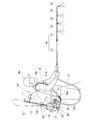
- FIG. 1 shows that the worker Mn carries out the spraying work while carrying the shoulder type power sprayer 10.
- a shoulder-type power sprayer 10 includes a liquid tank 11, a pump 15 that discharges liquid in the liquid tank 11, and an engine 16 that drives the pump 15.
- the working machine Mn can carry the spraying work on the back.
- the carrying type power sprayer 10 is abbreviated as “power sprayer 10”.
- the liquid tank 11, the pump 15, and the engine 16 are assembled to a frame 17 that is substantially L-shaped in a side view.
- the frame 17 is also called a backpack frame, and is a substantially vertical plate-like backboard portion 21 on the front side that is carried by the worker Mn, and a substantially flat plate-like horizontal plate portion 22 extending rearward from the lower end of the backpack portion 21. It consists of.
- the liquid tank 11 has a front surface 11 a attached to the back surface of the shoulder portion 21 and a lower surface attached to the upper surface 22 a of the horizontal plate portion 22 by a stay 23.
- the pump 15 is located below the liquid tank 11 on the front side carried by the worker Mn and is attached to the upper surface 22 a of the horizontal plate portion 22.
- the engine 16 is located below the liquid tank 11 and behind the pump 15, and is attached to the upper surface 22 a of the horizontal plate portion 22.
- the worker Mn can carry the power sprayer 10 by the left and right shoulder belts 18.
- One end portions 18 a of the left and right shoulder belts 18 are attached to the front lower portion of the frame 17.
- the other end 18b of the left and right shoulder belts 18 is attached to the upper portion of the front surface 11a of the liquid tank 11, that is, the surface 11a to be carried by the operator.
- the power sprayer 10 includes a spray pipe 19 connected to the discharge port 15 a of the pump 15 by the hose 12.
- the spray pipe 19 includes a large-diameter first spray pipe 13 connected to the hose 12 and a small-diameter second spray pipe 14 connected to the first spray pipe 13.
- the first spray pipe 13 is composed of a metal round pipe.
- the second spray pipe 14 is also called an extension pipe, and is constituted by a metal round pipe.
- the first spray pipe 13 and the second spray pipe 14 are held by a holding portion 40 (also referred to as a pipe holding portion 40) when not in use.
- the holding unit 40 is attached to the liquid tank 11.
- the end of the second spray pipe 14 is screwed onto the tip of the first spray pipe 13.
- the second spray pipe 14 includes a number of spray nozzles 32. For this reason, the liquid can be spread over a wider range.
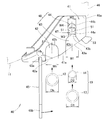
- the holding portion 40 is configured to hold the hose 12 and the spray pipe 19, and is located at the right rear portion or the left rear portion of the liquid tank 11. In consideration of the spraying workability by the first spraying pipe 13, it is preferable that the holding portion 40 is located on the dominant hand side of the worker Mn. More specifically, as shown in FIGS. 3 to 5, the holding portion 40 includes a holding body 41, a hose storage recess 42, a pipe storage recess 48, and a belt 45.
- the pipe storage recess 48 includes a first pipe storage recess 43 and a second pipe storage recess 44.
- a mounting seat 46 protruding rearward is formed on the outer surface of the liquid tank 11.
- the holding body 41 made of resin is overlapped on the rear surface 46a of the mounting seat 46 and is attached by a fastening member (not shown) such as a screw.
- the upper and lower surfaces of the holding body 41 are formed on a substantially horizontal flat surface.
- the rear surface 41a of the holding body 41 is formed as an inclined surface that is inclined forward as it goes from the width center side of the liquid tank 11 to the outer side in the width direction.
- the rear surface 41a is a surface on the opposite side to the backpack 21 of the frame 17 shown in FIG.
- Each of the storage recesses 42, 43, 44 is configured by a substantially U-shaped groove that penetrates in the vertical direction in a plan view, and is formed integrally with the resin-made holding body 41. All the openings 42 a, 43 a, 44 a of the storage recesses 42, 43, 44 face the rear surface 41 a of the holding body 41. The bottom surfaces 42b, 43b, 44b of the storage recesses 42, 43, 44 face forward.
- the hose storage recess 42 is a recess capable of storing a part of the hose 12, and has a bottom surface 42b having a semicircular shape in plan view.
- the position of the hose housing recess 42 with respect to the holding body 41 is preferably set closer to the center of the width of the liquid tank 11.
- the width Wh of the hose housing recess 42 is set to a size that allows the hose 12 to be easily inserted and removed and to hold the hose 12 stably, that is, slightly larger than the outer diameter Dh of the hose 12. (Wh> Dh).
- the first pipe storage recess 43 is a large recess capable of storing a part of the first spray pipe 13 having a large diameter, and has a bottom surface 43b having a semicircular shape in plan view.
- the opening 43a of the first pipe storage recess 43 is located adjacent to the opening 42a of the hose storage recess 42, preferably on the outer side in the width direction of the liquid tank 11 with respect to the opening 42a of the hose storage recess 42.
- the opening 42 a and the opening 43 a are located on the rear surface 41 a of the holding body 41.
- the width W1 of the first pipe storage recess 43 is set to a size that allows the first spray pipe 13 to be easily inserted and removed, that is, slightly larger than the outer diameter D1 of the first spray pipe 13 (W1). > D1). Furthermore, the width W1 of the first pipe storage recess 43 is substantially the same as the width Wh of the hose storage recess 42. (W1 ⁇ Wh)
- the second pipe storage recess 44 is a small recess capable of storing a part of the second spray pipe 14 having a small diameter, and has a bottom surface 44b having a semicircular shape in plan view.
- the opening 44a of the second pipe storage recess 44 is located behind and adjacent to the bottom surface 43b of the first pipe storage recess 43 (on the front surface 11a side of the liquid tank 11 shown in FIG. 3). It penetrates through the inside 43 c of the recess 43. That is, the opening 44 a of the second pipe housing recess 44 communicates with the inside 43 c of the first pipe housing recess 43 by the communication groove 47.
- the communication groove 47 passes through the holding body 41 in the vertical direction.
- the width W2 of the second pipe storage recess 44 is set to a size that allows the second spray pipe 14 to be easily inserted and removed, that is, slightly larger than the outer diameter D2 of the second spray pipe 14 (W2). > D2).
- the width W3 of the communication groove 47 is set to be the same as or slightly larger than the width W2 of the second pipe housing recess 44 (W3 ⁇ W2). The presence or absence of the communication groove 47 is arbitrary.
- left and right retaining projections 51 for retaining the second spray pipe 14 accommodated in the second pipe housing recess 44 so as to be pulled out, 51 is formed.
- the left and right retaining projections 51, 51 are formed by narrowing the opening 44 a of the second pipe housing recess 44.
- the left and right retaining projections 51, 51 are formed in a substantially triangular shape in plan view with the apexes facing each other.
- the width W4 of the opening 44a of the second pipe housing recess 44 that is, the interval W4 between the left and right retaining projections 51, 51 is slightly smaller than the outer diameter D2 of the second spray pipe 14 (W4 ⁇ D2).
- left and right retaining projections 51, 51 may have only one configuration. Even in that case, the width of the opening 44a of the second pipe housing recess 44 is W4.
- a part of the second spray pipe 14 can be stored and held by the following procedure.
- the second spraying pipe 14 removed from the first spraying pipe 13 is inserted vertically into the interior 43 c of the first pipe housing recess 43, and , And push it into the left and right retaining projections 51, 51.
- a part of the resin-made holding main body 41 is elastically deformed, so that the left and right retaining protrusions 51 and 51 are spread.
- the second spray pipe 14 enters the second pipe housing recess 44 while expanding the left and right retaining projections 51, 51. 6 and 7, the second spray pipe 14 is stored and held in the second pipe storage recess 44 in a vertically oriented posture. As a result, the second spray pipe 14 can be held on the holding body 41.
- the force that spreads the left and right retaining projections 51, 51 by the second spray pipe 14 can be easily put in and out of the second pipe housing recess 44, and reliably the second pipe housing recess 44. Is set to a small force that can be held in.
- the belt 45 is a flexible member for opening and closing the opening 42a of the hose housing recess 42 and the opening 43a of the first pipe housing recess 43.
- the belt 45 closes the opening 42a of the hose housing recess 42 so that the hose 12 can be held in the hose housing recess 42, and the first pipe can hold the first spray pipe 13 in the first pipe housing recess 43.
- It is a member that closes the opening 43 a of the storage recess 43. Both the hose 12 and the first spray pipe 13 can be held on the holding body 41 by the single belt 45.
- one end 45 a of the belt 45 is attached to one end in the width direction of the holding body 41.
- the attachment position of the one end 45 a of the belt 45 with respect to the holding body 41 is preferably set near the width center of the liquid tank 11.
- a hooking hole 52 is formed in the other end 45 b of the belt 45.
- the latching hole 52 is detachably latched to the latching hook 53 formed at the other end in the width direction of the holding body 41.
- the hose storage recess 42 and the first pipe storage recess 43 can store and hold each part of the hose 12 and the first spray pipe 13 by the following procedure.
- the belt 45 is routed along the rear surface 41 a of the holding body 41, and the latching hole 52 is hooked on the latching hook 53.
- the opening 42 a of the hose housing recess 42 and the opening 43 a of the first pipe housing recess 43 are closed by the belt 45.
- the first spreading pipe 13 is pressed against the bottom 43 b of the first pipe housing recess 43 by the belt 45.
- the depth Hh from the opening 42a to the bottom surface 42b of the hose housing recess 42 is set to be larger than the outer diameter Dh of the hose 12 (Hh> Dh). For this reason, as shown in FIG. 7, when the opening 42 a of the hose housing recess 42 is closed by the belt 45, a gap is formed between the hose 12 and the belt 45. There is no fear that the hose 12 housed in the hose housing recess 42 will be crushed by the belt 45. Accordingly, the durability of the hose 12 can be sufficiently ensured.
- the depth Hh is set to a distance from the opening 42a to the bottom surface 42b at the center of the width of the hose housing recess 42.
- the hose 12 can be extracted from the hose storage recess 42, and the first spray pipe 13 can be extracted from the first pipe storage recess 43.
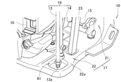
- FIGS. 2, 8, and 9 the frame 17 for providing the liquid tank 11 has a concave receiving portion 61 opened upward.
- FIG. 8 shows a state in which the lower end 13 a of the first spray pipe 13 is placed on the receiving portion 61.
- FIG. 9 shows a state before the lower end 13 a of the first spreading pipe 13 is placed on the receiving portion 61.
- the receiving portion 61 is constituted by a recess formed in the upper surface 22 a of the horizontal plate portion 22 of the frame 17.
- the receiving portion 61 can receive at least the lower end 13 a of the first spreading pipe 13 held by the holding portion 40.
- diffusion pipe 13 can be hold
- the liquid dripping from the lower end 13 a of the first spray pipe 13 that has been used can be received by the receiving portion 61. There is no worry of soiling the surroundings with the dripping liquid.
- the receiving part 61 can receive at least the lower end 13a of the spray pipe 19 (particularly the first spray pipe 13) held by the holding part 40. For this reason, the spreading pipe 19 can be held more stably by the two portions of the holding portion 40 and the receiving portion 61. Moreover, the liquid dripping from the lower end 13 a of the spray pipe 19 that has been used can be received by the receiving portion 61. There is no worry of soiling the surroundings with the dripping liquid.
- the holding unit 40 is connected to the hose storage recess 42 for storing a part of the hose 12 connected to the discharge port 15 a of the pump 15 and the hose 12.
- a pipe storage recess 48 (particularly the first pipe storage recess 43) for storing a part of the spray pipe 19 (particularly the first spray pipe 13) to be opened, and a belt for opening and closing the pipe storage recess 48 and the hose storage recess 42 45.
- the hose storage recess 42 and the pipe storage recess 48 can be opened and closed easily and quickly by the single belt 45. Therefore, the hose 12 and the spray pipe 19 connected to the hose 12 can be easily and quickly held and taken out from the holding portion 40. In addition, when the spray pipe 19 is not used, it is not necessary to move the hose 12 while holding the hose 12 on the hose holding portion 40 while holding the hose 12 by hand.
- the hose 12 and the spray pipe 19 can be stored in the holding portion 40 in a space efficient manner. Therefore, the holding structure for holding the hose 12 and the spray pipe 19 connected to the hose 12 by the holding unit 40 can be made small and easy to use.
- the opening 43 a of the first pipe storage recess 43 is adjacent to the opening 42 a of the hose storage recess 42.
- the opening 42a of the hose storage recess 42 and the opening 43a of the first pipe storage recess 43 can be easily and quickly opened and closed by the single belt 45. Therefore, the hose 12 and the first spray pipe 13 connected to the hose 12 can be easily and quickly held and taken out from the holding portion 40.
- the first spray pipe 13 is not used, it is not necessary to move the hose 12 while holding the hose 12 by the holding portion 40 while holding the hose 12 by hand.
- the opening 44 a of the second pipe storage recess 44 is located behind the bottom surface 43 b of the first pipe storage recess 43 and penetrates the inside 43 c of the first pipe storage recess 43.
- the second spreading pipe 14 is held by left and right retaining projections 51, 51 on the back side of the first pipe housing recess 43. Therefore, the second spray pipe 14 removed from the first spray pipe 13 can be easily held in the second pipe housing recess 44.
- the worker Mn does not need to carry the second spray pipe 14 by hand. Further, when storing the power sprayer 10, the second spray pipe 14 may not be separately provided. For this reason, there is no worry of losing the second spray pipe 14.
- the holding unit 40 can be reduced in size.
- the hose 12, the first spray pipe 13, and the second spray pipe 14, that is, all of the so-called three spray pipes 12, 13, and 14 can be stored in the holding unit 40 in a space efficient manner.
- the spray pipe 19 is not limited to the combined structure of the first spray pipe 13 and the second spray pipe 14, and for example, only one of the first spray pipe 13 and the second spray pipe 14 is used. Includes configuration.
- the pipe storage recess 48 includes only one of the first pipe storage recess 43 and the second pipe storage recess 44.
- the hose storage recess 42 and the pipe storage recess 48 include a configuration arranged in a straight line.
- the opening 42 a of the hose housing recess 42 is located on the rear surface 41 a of the holding body 41, and the opening 43 a of the first pipe housing recess 43 is located on the bottom surface 42 b of the hose housing recess 42.
- the backpack type power sprayer 10 of the present invention is suitable for a spraying operation on a large farm.
Abstract
Description
11 液タンク
12 ホース
13 第1散布パイプ
13a 下端
14 第2散布パイプ
15 ポンプ
15a ポンプの吐出口
16 エンジン
17 フレーム
19 散布パイプ
40 保持部
42 ホース収納凹部
42a 開口
43 第1パイプ収納凹部
43a 開口
43b 底面
43c 内部
44 第2パイプ収納凹部
44a 開口
45 ベルト
48 パイプ収納凹部
51 抜止め凸部
61 受け部
Dh ホースの外径
Hh ホース収納凹部の開口から底面までの奥行き
Mn 作業者 DESCRIPTION OF
Claims (5)
- 液タンクの中の液体を吐出する動力駆動式のポンプと、該ポンプの吐出口にホースによって接続される散布パイプとを備えた、背負い式動力噴霧機であって、
前記ホースと前記散布パイプとを保持するための保持部を備え、
該保持部は、前記ホースの一部を収納するためのホース収納凹部と、前記散布パイプの一部を収納するためのパイプ収納凹部と、該パイプ収納凹部及び前記ホース収納凹部を開閉するためのベルトとを、含むことを特徴とする背負い式動力噴霧機。 A backpack-type power sprayer comprising a power-driven pump that discharges liquid in a liquid tank, and a spray pipe that is connected to a discharge port of the pump by a hose,
A holding portion for holding the hose and the spray pipe;
The holding portion includes a hose storage recess for storing a part of the hose, a pipe storage recess for storing a part of the spray pipe, and opening and closing the pipe storage recess and the hose storage recess. And a belt-type power sprayer. - 前記保持部に保持された前記散布パイプの少なくとも下端を受けるための受け部を、更に有している、請求項1記載の背負い式動力噴霧機。 The backpack type power sprayer according to claim 1, further comprising a receiving portion for receiving at least a lower end of the spray pipe held by the holding portion.
- 前記散布パイプは、前記ホースに接続される大径の第1散布パイプと、該第1散布パイプに接続される小径の第2散布パイプとからなり、
前記ホース収納凹部は、断面略U字状に形成され、
前記パイプ収納凹部は、前記大径の第1散布パイプの一部を収納するための断面略U字状の大きい第1パイプ収納凹部と、前記小径の第2散布パイプの一部を収納するための断面略U字状の小さい第2パイプ収納凹部とからなり、
前記第1パイプ収納凹部の開口は、前記ホース収納凹部の開口に隣接し、
前記第2パイプ収納凹部の開口は、前記第1パイプ収納凹部の底面の後ろに位置するとともに、該第1パイプ収納凹部の内部に貫通し、
前記第2パイプ収納凹部の開口又はその近傍には、前記第2パイプ収納凹部に収納されている前記第2散布パイプを引き抜き可能に抜け止めするための抜止め凸部が形成され、
前記ベルトは、前記ホース収納凹部内に前記ホースを保持可能に前記ホース収納凹部の開口を塞ぐとともに、前記第1パイプ収納凹部内に前記第1散布パイプを保持可能に前記第1パイプ収納凹部の開口を塞ぐ部材である、請求項1記載の背負い式動力噴霧機。 The spray pipe is composed of a large-diameter first spray pipe connected to the hose and a small-diameter second spray pipe connected to the first spray pipe,
The hose housing recess is formed in a substantially U-shaped cross section,
The pipe storage recess is for storing a first pipe storage recess having a large U-shaped cross section for storing a part of the large-diameter first spray pipe and a part of the small-diameter second spray pipe. The second pipe storage recess having a small U-shaped cross section,
The opening of the first pipe storage recess is adjacent to the opening of the hose storage recess,
The opening of the second pipe storage recess is located behind the bottom surface of the first pipe storage recess and penetrates into the first pipe storage recess,
At or near the opening of the second pipe housing recess, a retaining projection for preventing the second spraying pipe housed in the second pipe housing recess from being pulled out is formed,
The belt closes the opening of the hose storage recess so as to hold the hose in the hose storage recess, and also holds the first spray pipe in the first pipe storage recess. The backpack type power sprayer according to claim 1, which is a member for closing the opening. - 前記液タンクを設けるためのフレームを、更に有し、
該フレームは、前記保持部に保持された少なくとも前記第1散布パイプの下端を受けるための受け部を有し、
前記受け部は、上に開口した凹状に形成されている、請求項3記載の背負い式動力噴霧機。 A frame for providing the liquid tank;
The frame has a receiving part for receiving at least a lower end of the first spray pipe held by the holding part,
The shoulder type power sprayer according to claim 3, wherein the receiving portion is formed in a concave shape opened upward. - 前記ホース収納凹部の前記開口から底面までの奥行きは、前記ホースの外径よりも大きく設定されている、請求項3記載の背負い式動力噴霧機。 The shoulder-type power sprayer according to claim 3, wherein a depth from the opening to the bottom surface of the hose housing recess is set larger than an outer diameter of the hose.
Priority Applications (3)
| Application Number | Priority Date | Filing Date | Title |
|---|---|---|---|
| MX2016007608A MX2016007608A (en) | 2013-12-11 | 2014-12-05 | Backpack power sprayer. |
| BR112016001749-8A BR112016001749B1 (en) | 2013-12-11 | 2014-12-05 | backpack motorized sprayer |
| CN201480019575.6A CN105101789B (en) | 2013-12-11 | 2014-12-05 | Backpack powered sprayer |
Applications Claiming Priority (2)
| Application Number | Priority Date | Filing Date | Title |
|---|---|---|---|
| JP2013256178A JP2015112057A (en) | 2013-12-11 | 2013-12-11 | Knapsack power sprayer |
| JP2013-256178 | 2013-12-11 |
Publications (1)
| Publication Number | Publication Date |
|---|---|
| WO2015087805A1 true WO2015087805A1 (en) | 2015-06-18 |
Family
ID=53371110
Family Applications (1)
| Application Number | Title | Priority Date | Filing Date |
|---|---|---|---|
| PCT/JP2014/082271 WO2015087805A1 (en) | 2013-12-11 | 2014-12-05 | Backpack power sprayer |
Country Status (6)
| Country | Link |
|---|---|
| JP (1) | JP2015112057A (en) |
| CN (2) | CN105101789B (en) |
| BR (1) | BR112016001749B1 (en) |
| MX (1) | MX2016007608A (en) |
| PE (1) | PE20160350A1 (en) |
| WO (1) | WO2015087805A1 (en) |
Cited By (4)
| Publication number | Priority date | Publication date | Assignee | Title |
|---|---|---|---|---|
| WO2018011011A1 (en) * | 2016-07-11 | 2018-01-18 | Bayer Cropscience Aktiengesellschaft | Spray device with unpressurised spray material containers |
| WO2018077486A1 (en) * | 2016-10-27 | 2018-05-03 | Husqvarna Ab | Adapter for fluid dispensing system |
| WO2020239664A1 (en) | 2019-05-31 | 2020-12-03 | Bayer Aktiengesellschaft | Monitoring module for sprayers |
| CN112772614A (en) * | 2020-12-31 | 2021-05-11 | 广州极飞科技股份有限公司 | Spraying method and device for plant protection equipment, plant protection equipment and processor |
Families Citing this family (1)
| Publication number | Priority date | Publication date | Assignee | Title |
|---|---|---|---|---|
| CN108580085B (en) * | 2018-05-10 | 2019-12-13 | 金华星凯利亚家俬有限公司 | portable waterproof agent spraying machine |
Citations (5)
| Publication number | Priority date | Publication date | Assignee | Title |
|---|---|---|---|---|
| JPS62103457U (en) * | 1985-12-20 | 1987-07-01 | ||
| JPH01179762U (en) * | 1988-06-07 | 1989-12-25 | ||
| US5775591A (en) * | 1996-08-16 | 1998-07-07 | Fauci; Dino A. | Portable pressure cleaning device |
| US6945438B1 (en) * | 2005-01-26 | 2005-09-20 | Chun-Chia Shih | Pesticide spraying cart |
| US20090008476A1 (en) * | 2005-03-04 | 2009-01-08 | Central Agricola Bovi, S.L. | Portable Agricultural Sprayer |
Family Cites Families (6)
| Publication number | Priority date | Publication date | Assignee | Title |
|---|---|---|---|---|
| CN2372067Y (en) * | 1999-06-25 | 2000-04-05 | 王金龙 | Electric spraying device |
| JP3746755B2 (en) * | 2002-10-16 | 2006-02-15 | 株式会社共立 | Power sprayer |
| CN202501110U (en) * | 2012-04-18 | 2012-10-24 | 黄永怀 | Rapid detachable pipeline fixing device |
| CN202751672U (en) * | 2012-09-19 | 2013-02-27 | 曾华萍 | Medical catheter fixing device |
| CN203091164U (en) * | 2013-01-31 | 2013-07-31 | 台州市丰田喷洗机有限公司 | Backpack type electric sprayer |
| CN103329879A (en) * | 2013-07-16 | 2013-10-02 | 赵明 | Agricultural backpacking type backward spraying machine |
-
2013
- 2013-12-11 JP JP2013256178A patent/JP2015112057A/en active Pending
-
2014
- 2014-12-05 MX MX2016007608A patent/MX2016007608A/en unknown
- 2014-12-05 BR BR112016001749-8A patent/BR112016001749B1/en active IP Right Grant
- 2014-12-05 WO PCT/JP2014/082271 patent/WO2015087805A1/en active Application Filing
- 2014-12-05 PE PE2016000117A patent/PE20160350A1/en active IP Right Grant
- 2014-12-05 CN CN201480019575.6A patent/CN105101789B/en active Active
- 2014-12-05 CN CN201710089776.9A patent/CN107008590B/en active Active
Patent Citations (5)
| Publication number | Priority date | Publication date | Assignee | Title |
|---|---|---|---|---|
| JPS62103457U (en) * | 1985-12-20 | 1987-07-01 | ||
| JPH01179762U (en) * | 1988-06-07 | 1989-12-25 | ||
| US5775591A (en) * | 1996-08-16 | 1998-07-07 | Fauci; Dino A. | Portable pressure cleaning device |
| US6945438B1 (en) * | 2005-01-26 | 2005-09-20 | Chun-Chia Shih | Pesticide spraying cart |
| US20090008476A1 (en) * | 2005-03-04 | 2009-01-08 | Central Agricola Bovi, S.L. | Portable Agricultural Sprayer |
Cited By (11)
| Publication number | Priority date | Publication date | Assignee | Title |
|---|---|---|---|---|
| WO2018011011A1 (en) * | 2016-07-11 | 2018-01-18 | Bayer Cropscience Aktiengesellschaft | Spray device with unpressurised spray material containers |
| WO2018011009A1 (en) * | 2016-07-11 | 2018-01-18 | Bayer Cropscience Aktiengesellschaft | Spray device with flow measurement |
| CN109475114A (en) * | 2016-07-11 | 2019-03-15 | 拜耳农作物科学股份公司 | Spraying apparatus with non-pressure atomization containers |
| US10940497B2 (en) | 2016-07-11 | 2021-03-09 | Bayer Cropscience Aktiengesellschaft | Intelligent spray system |
| WO2018077486A1 (en) * | 2016-10-27 | 2018-05-03 | Husqvarna Ab | Adapter for fluid dispensing system |
| CN109922894A (en) * | 2016-10-27 | 2019-06-21 | 富世华股份有限公司 | Adapter for liquid dispensing system |
| CN109922894B (en) * | 2016-10-27 | 2021-09-24 | 富世华股份有限公司 | Adapter for liquid dispensing system |
| CN113546779A (en) * | 2016-10-27 | 2021-10-26 | 富世华股份有限公司 | Adapter for liquid dispensing system |
| WO2020239664A1 (en) | 2019-05-31 | 2020-12-03 | Bayer Aktiengesellschaft | Monitoring module for sprayers |
| CN112772614A (en) * | 2020-12-31 | 2021-05-11 | 广州极飞科技股份有限公司 | Spraying method and device for plant protection equipment, plant protection equipment and processor |
| CN112772614B (en) * | 2020-12-31 | 2022-11-08 | 广州极飞科技股份有限公司 | Spraying method and device for plant protection equipment, plant protection equipment and processor |
Also Published As
| Publication number | Publication date |
|---|---|
| BR112016001749A8 (en) | 2020-01-21 |
| CN105101789B (en) | 2017-03-15 |
| CN107008590A (en) | 2017-08-04 |
| MX2016007608A (en) | 2017-03-20 |
| BR112016001749A2 (en) | 2017-08-01 |
| PE20160350A1 (en) | 2016-05-26 |
| CN105101789A (en) | 2015-11-25 |
| BR112016001749B1 (en) | 2022-04-05 |
| JP2015112057A (en) | 2015-06-22 |
| CN107008590B (en) | 2020-05-19 |
Similar Documents
| Publication | Publication Date | Title |
|---|---|---|
| WO2015087805A1 (en) | Backpack power sprayer | |
| US9140398B2 (en) | Air aspiration device | |
| CA3019002C (en) | Push on/pull off protective cap for fire protection sprinklers | |
| US9616444B2 (en) | High pressure water cleaner with detachable water tank | |
| FR3061662A1 (en) | APPARATUS AND METHOD FOR SPREADING MIXTURE OF A LIQUID AND A FIRST FLUID | |
| JP2016201335A (en) | Light source unit and luminaire | |
| US9517552B2 (en) | Filter remover | |
| FR2982850B1 (en) | DISTRIBUTION HEAD FOR A SYSTEM FOR DISTRIBUTING A PRESSURIZED PRODUCT | |
| JP5813079B2 (en) | Backpack power sprayer | |
| US10215377B2 (en) | Light assembly and a method of securing the light assembly into an opening in a thin wall | |
| KR101537867B1 (en) | Setting apparatus for washer | |
| JP6708024B2 (en) | Connector and luminaire with connector | |
| JP2015112535A5 (en) | ||
| KR200408329Y1 (en) | Auto knapsack pump | |
| JP5872996B2 (en) | Backside spreader | |
| JP6521706B2 (en) | lighting equipment | |
| CA2742634A1 (en) | High pressure water cleaner with detachable water tank | |
| KR102056346B1 (en) | Cable connection terminal holder | |
| KR101744862B1 (en) | Assembly structure of cowl top for hose | |
| JP2006046508A (en) | Stud fixture | |
| KR200419315Y1 (en) | a bill exclusion | |
| EP3138745B1 (en) | Wiper device for cleaning vehicle windows | |
| JP6284815B2 (en) | Fall prevention tool | |
| JP2014193649A (en) | Vehicle washing equipment | |
| JP2020039541A (en) | Belt attachment device |
Legal Events
| Date | Code | Title | Description |
|---|---|---|---|
| WWE | Wipo information: entry into national phase |
Ref document number: 201480019575.6 Country of ref document: CN |
|
| 121 | Ep: the epo has been informed by wipo that ep was designated in this application |
Ref document number: 14868732 Country of ref document: EP Kind code of ref document: A1 |
|
| WWE | Wipo information: entry into national phase |
Ref document number: IDP00201600569 Country of ref document: ID |
|
| WWE | Wipo information: entry into national phase |
Ref document number: 000117-2016 Country of ref document: PE |
|
| REG | Reference to national code |
Ref country code: BR Ref legal event code: B01A Ref document number: 112016001749 Country of ref document: BR |
|
| WWE | Wipo information: entry into national phase |
Ref document number: MX/A/2016/007608 Country of ref document: MX |
|
| NENP | Non-entry into the national phase |
Ref country code: DE |
|
| 122 | Ep: pct application non-entry in european phase |
Ref document number: 14868732 Country of ref document: EP Kind code of ref document: A1 |
|
| ENP | Entry into the national phase |
Ref document number: 112016001749 Country of ref document: BR Kind code of ref document: A2 Effective date: 20160127 |