WO2015087713A1 - Attachment for stethoscope - Google Patents
Attachment for stethoscope Download PDFInfo
- Publication number
- WO2015087713A1 WO2015087713A1 PCT/JP2014/081504 JP2014081504W WO2015087713A1 WO 2015087713 A1 WO2015087713 A1 WO 2015087713A1 JP 2014081504 W JP2014081504 W JP 2014081504W WO 2015087713 A1 WO2015087713 A1 WO 2015087713A1
- Authority
- WO
- WIPO (PCT)
- Prior art keywords
- tube
- mounting
- tube portion
- stethoscope
- operation piece
- Prior art date
Links
Images


Classifications
-
- A—HUMAN NECESSITIES
- A61—MEDICAL OR VETERINARY SCIENCE; HYGIENE
- A61B—DIAGNOSIS; SURGERY; IDENTIFICATION
- A61B90/00—Instruments, implements or accessories specially adapted for surgery or diagnosis and not covered by any of the groups A61B1/00 - A61B50/00, e.g. for luxation treatment or for protecting wound edges
- A61B90/50—Supports for surgical instruments, e.g. articulated arms
- A61B90/57—Accessory clamps
-
- A—HUMAN NECESSITIES
- A61—MEDICAL OR VETERINARY SCIENCE; HYGIENE
- A61B—DIAGNOSIS; SURGERY; IDENTIFICATION
- A61B7/00—Instruments for auscultation
-
- A—HUMAN NECESSITIES
- A61—MEDICAL OR VETERINARY SCIENCE; HYGIENE
- A61B—DIAGNOSIS; SURGERY; IDENTIFICATION
- A61B7/00—Instruments for auscultation
- A61B7/02—Stethoscopes
-
- A—HUMAN NECESSITIES
- A61—MEDICAL OR VETERINARY SCIENCE; HYGIENE
- A61B—DIAGNOSIS; SURGERY; IDENTIFICATION
- A61B2560/00—Constructional details of operational features of apparatus; Accessories for medical measuring apparatus
- A61B2560/04—Constructional details of apparatus
- A61B2560/0443—Modular apparatus
Definitions
- the present invention relates to an attachment for a stethoscope attached to a stethoscope.
- a sound collection unit for detecting auscultation sounds and an ear branched into a left tube unit and a right tube unit so as to be inserted into the left and right ears of the user There are pipes that are connected to each other using a connecting pipe such as a rubber pipe.
- a connecting pipe such as a rubber pipe.
- the interval between the left tube portion and the right tube portion is set with respect to the ear canal that is close to each other by its own elastic force.
- An operation for applying an external force in the extending direction is required. Therefore, in order to wear a stethoscope, it is necessary to use both hands of a user, such as a doctor.
- the temporomandibular joint stethoscope for screening disclosed in Patent Document 1 described above can be mounted on the ear canal by one hand by providing the spring-type gripper on the ear canal mounted on the examiner.
- the spring type gripper in the said invention cannot be retrofitted with respect to an ear canal part.
- the spring type grasper in the said invention it is not assumed that it retrofits with respect to the existing stethoscope, and no consideration is made. For this reason, it cannot be attached to an existing stethoscope that is usually used by doctors and the like, and cannot be used well.
- the stethoscope Since the stethoscope is used by being attached to the body of a doctor or the like, it is conceivable that the stethoscope is properly used depending on the preference or application of the doctor or the like. Therefore, it is strongly desired to provide an attachment that can be used without any problem by being attached to an arbitrary stethoscope such as an existing stethoscope.
- the first member and the second member are formed in a large circular shape, and this is a branch portion of the connecting pipe described later. It protrudes further upward. This hits the user's chin and gets in the way. If it is going to avoid this, the branch part of a connecting pipe must be greatly lowered below, and a commercially available stethoscope cannot be used.
- the present invention can use a normal stethoscope selected by a doctor according to his / her own preference and application.
- an object of the present invention is to provide an attachment for a stethoscope that can be attached to any stethoscope and can be operated with no problem.
- the present inventor has completed the attachment for the stethoscope of the present invention as a result of earnest research, and the feature thereof is that the sound collecting unit 2 for detecting the auscultatory sound and the use
- the ear tube 3 having the left tube portion 3a and the right tube portion 3b branched so as to be inserted into the left and right ears of the person, and the sound collecting portion 2, the left tube portion 3a, and the right tube portion 3b.
- a connecting pipe 4, and the left pipe part 3 a and the right pipe part 3 b are biased in a direction close to each other via the connecting pipe by the elastic force of the connecting pipe 4, and the left pipe part 3 a and What is the biasing direction with respect to one end of the left tube 3a and one end of the right tube 3b covered with the end of the right tube 3b or the connecting tube 4 on the ear tube 3 side?
- the interval between the left tube portion 3a and the right tube portion 3b is expanded.
- the operating unit 22 and the mounting unit 20 are connected by a rotatable hinge unit 18 so that the mounting unit 20 is opened and closed by opening and closing the operating unit 22, and the hinge unit is connected to a stethoscope. When mounted, it is located outside the region surrounded by the left tube portion 3a, the right tube portion 3b, and the connection tube 4.
- the attachment for a stethoscope of the present invention can freely attach and detach the left operating piece and the right operating piece with respect to the left tube portion and the right tube portion, respectively. Therefore, the attachment for stethoscopes of this invention can be attached and used with respect to the arbitrary stethoscopes selected according to liking of a doctor etc., for example.
- the attachment for the stethoscope of the present invention can be operated in conjunction with the operation of the left operating piece mounting portion and the right operating piece mounting portion only by performing an operation of bringing the operating portions of the left operating piece and the right operating piece close to each other. The distance between the left tube portion and the right tube portion can be expanded.
- a doctor or the like can expand the ear canal and attach it to the ear by an operation using only one hand. Therefore, by using the attachment for a stethoscope of the present invention, the work efficiency of a doctor or the like can be significantly improved.
- the attachment for a stethoscope of the present invention is mounted so that either one or both of the left operating piece and the mounting portion of the right operating piece can slide along the left tube portion or the right tube portion. It is desirable to be possible.
- the mounting portion when performing the expansion operation, the mounting portion is slid along the left tube portion or the right tube portion, and the load required to widen the interval between the left tube portion and the right tube portion of the ear canal is reduced. be able to. Therefore, according to the present invention, it is possible to provide an attachment for a stethoscope that can perform an expansion operation for making the ear canal an expanded state even more easily.
- the attachment for a stethoscope of the present invention described above is mounted such that one or both of the left operating piece and the mounting portion of the right operating piece are mounted so as to surround an outer periphery together with the left tube portion or the right tube portion. It can be attached by a member.
- the attachment for a stethoscope of the present invention described above is for mounting the mounting portion of one or both of the left operating piece and the mounting portion of the right operating piece to the left tube portion or the right tube portion.
- There is an annular member and the mounting portion is provided with an insertion portion through which the annular member can be inserted, and the annular member inserted through the insertion portion surrounds the left tube portion or the right tube portion.
- the hinge portion refers to a portion where the members are rotatably connected, and the shape and structure are not particularly limited. It is possible to simply provide a through hole in a crossing member and insert a shaft.
- a major point of the present invention is that the hinge portion is located outside the region surrounded by the left tube portion 3a, the right tube portion 3b, and the connection tube 4 when mounted on a stethoscope. That is, when the operating portion is operated and the width thereof is narrowed, the hinge portion moves upward, but the position moved upward is also located outside this region. As a result, it does not hit the user's chin or neck and does not get in the way.
- a stopper may be provided on the hinge portion of the present invention so that the left and right operation pieces do not become narrower than a certain size. That is, the stethoscope is in a state where the left and right operation pieces are close to each other by its own elastic force. If it approaches more than necessary, it may become trapped when expanding, which is troublesome. Therefore, it is preferable to provide a stopper on the hinge portion so that it is locked during rotation so that it does not shrink more than necessary (closer than it fits tightly into the user's ear).
- the left operation piece and the right operation piece can be more reliably attached to the left tube portion and the right tube portion of the ear canal.
- interval of a left pipe part and a right pipe part reliably in response to the operation
- FIG. 1 It is a perspective view which shows the state which attached the example of the attachment for stethoscopes of this invention to the stethoscope. It is a perspective view which shows one example of the attachment for stethoscopes of this invention. It is a perspective view which shows the state which attached the other example of the attachment for stethoscopes of this invention to the stethoscope. It is a perspective view which shows the modification of the mounting structure of the attachment for stethoscopes shown in FIG. It is a front view before assembling, showing another example of the attachment for the stethoscope of the present invention. It is a perspective view of what combined the penetration part and put the axis
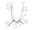
- the stethoscope 1 includes a sound collection unit 2, an ear canal 3, and a connection tube 4.
- the sound collection unit 2 is a portion provided for detecting auscultation sound by bringing it into contact with a sound collection target of auscultation sound such as a human body.
- the ear canal 3 is formed of a tubular body made of a metal tube or the like, and is bent so that it can be inserted into the left and right ears of a user such as a doctor.
- the ear canal 3 is branched into a left tube portion 3a and a right tube portion 3b, and ear pieces 3c and 3c are attached to a portion to be inserted into the user's ear on the distal end side.
- the eustachian tube 3 is biased in the direction in which the left tube portion 3a and the right tube portion 3b approach each other (in the direction of arrow F in FIG. 1) by its own elastic force.
- the ear canal 3 is in a state (expanded state) in which the interval between the left tube portion 3a and the right tube portion 3b is expanded by applying an external force in a direction opposite to the biasing direction described above (direction of arrow A in FIG. 1). can do.
- the user of the stethoscope 1 can insert and wear the earpieces 3c and 3c into both ears by setting the ear canal 3 to be in an expanded state and extending beyond the distance between his / her ears.
- the connection pipe 4 is a pipe for connecting the sound collection unit 2 and the ear canal 3.
- the connecting pipe 4 is constituted by a highly flexible pipe made of a rubber pipe or a resin pipe such as vinyl chloride.
- the connection tube 4 is constituted by one tube or one tube until it branches from the sound collecting portion 2 to the left tube portion 3a and the right tube portion 3b of the ear tube 3. It is possible to use appropriate ones such as one provided with a partition inside, one constituted by two pipes, and the like.
- the end portion on the ear tube 3 side partially covers the portions of the left tube portion 3 a and the right tube portion 3 b on the proximal end side (opposite to the ear pieces 3 c and 3 c side). Yes.
- the stethoscope attachment 10 is an attachment that is attached to the above-described stethoscope 1 and enables an operation for bringing the ear canal 3 into an expanded state.
- the stethoscope attachment 10 includes a pair of operation pieces 12 (hereinafter also referred to as a left operation piece 14 and a right operation piece 16 as necessary) and a hinge portion 18. .
- the operation piece 12 (the left operation piece 14 and the right operation piece 16) has a mounting part 20 on one end side and an operation part 22 on the other end side.
- the operation piece 12 is created by processing a wire such as a wire into a bent shape.
- the left operation piece 14 and the right operation piece 16 are substantially symmetrical in shape.
- the left operation piece 14 and the right operation piece 16 are configured such that the mounting portions 20 and 20 can be attached to and detached from the left tube portion 3a and the right tube portion 3b, respectively.
- the mounting portion 20 has a hook-like shape that is curved along the outer periphery of the left tube portion 3a and the right tube portion 3b, and is between the left tube portion 3a and the right tube portion 3b (inside). It can be attached to the left tube portion 3a and the right tube portion 3b so as to be hooked outward from the region X side formed in FIG.
- the mounting portions 20 and 20 of the left operation piece 14 and the right operation piece 16 are mounted on the portions covered by the connecting pipe 4 made of rubber or the like on the base end side of the left tube portion 3a and the right tube portion 3b. Has been. Therefore, the mounting portions 20 and 20 are mounted so as not to easily fall off due to a frictional force generated between the connecting portions 4 and 20.
- the operation unit 22 is provided on the operation piece 12 on the side opposite to the mounting unit 20.
- the operation unit 22 is a part where the user places a finger when operating the stethoscope attachment 10. Specifically, a finger such as a user's thumb is hung on one of the operation portions 22 and 22 of the left operation piece 14 and the right operation piece 16, and a finger such as an index finger is hung on the other. Then, as shown by an arrow B in FIG. 1, by performing an operation of picking the fingers hooked on the operation portions 22 and 22 of the left operation piece 14 and the right operation piece 16 close to each other, an arrow A in FIG. An operation of operating the left operation piece 14 and the right operation piece 16 in the direction shown can be executed.
- the hinge portion 18 is provided between the mounting portions 20 and 20 of the left operation piece 14 and the right operation piece 16 and the operation portions 22 and 22 so that the left operation piece 14 and the right operation piece 16 can be opened and closed. This is the part that connects to In the present embodiment, the hinge portion 18 is inserted by inserting the support shaft 24 made of a combination of a bolt and a nut into a hole-like portion formed by looping the wire rods forming the left operation piece 14 and the right operation piece 16. Is formed. Moreover, in this embodiment, the hinge part 18 is provided in both the front side and back side in the mounting state to the stethoscope 1. FIG.
- the stethoscope attachment 10 holds the operation portions 22, 22 and brings the operation portion 22 of the left operation piece 14 and the operation portion 22 of the right operation piece 16 close to each other in FIG.
- the interval between the mounting portion 20 of the left operation piece 14 and the mounting portion 20 of the right operation piece 16 can be expanded.
- an external force can be applied to the left tube portion 3a and the right tube portion 3b, and an operation (expansion operation) for expanding the distance between the two can be performed. Therefore, by using the stethoscope attachment 10, a user such as a doctor can expand the ear canal 3 and attach it to the ear by an operation using only one hand.
- the ear canal 3 returns to the original state by the elastic force of the ear canal 3 itself. Therefore, after the eustachian tube 3 expanded in the direction of the arrow A by the expansion operation is applied to the user's ear, it is possible to complete the wearing of the stethoscope 1 by stopping the operation portions 22 and 22 from being picked. . Further, when the user wants to remove the stethoscope 1, the stethoscope 1 can be removed by an operation of simply grasping the operation units 22 and 22 and expanding the ear canal 3.
- the stethoscope attachment 10 can easily attach and detach the stethoscope 1 only by operating the operation units 22 and 22 with one hand. Therefore, by using the attachment 10 for a stethoscope, the working efficiency of a doctor or the like can be significantly improved.
- the above-described stethoscope attachment 10 can be used by being attached to any stethoscope 1 selected by a doctor or the like. Therefore, according to the attachment 10 for stethoscopes, it is possible to attach and detach various types of stethoscopes 1 selected according to the preference or use of a doctor or the like with one hand.
- an attachment 100 for a stethoscope according to a second embodiment of the present invention will be described with reference to an example of mounting on the stethoscope 1 described above.
- the attachment 100 for stethoscopes of this embodiment about the structure which is common with the attachment 10 for stethoscopes of 1st Embodiment mentioned above, what added 100 to the code
- the stethoscope attachment 100 is an attachment that is attached to the stethoscope 1 in the same manner as the above-described stethoscope attachment 10 and enables an operation for bringing the ear canal 3 into an expanded state.
- the stethoscope attachment 10 includes a pair of operation pieces 112 (hereinafter also referred to as a left operation piece 114 and a right operation piece 116 as necessary) and a hinge portion 118.
- the attachment 100 for the stethoscope includes the mounting member 130 for mounting the left operation piece 114 and the right operation piece 116 to the left tube portion 3a and the right tube portion 3b of the ear canal 3 as described above.
- the configuration is different from that of the stethoscope attachment 10.
- the operation piece 112 (the left operation piece 114 and the right operation piece 116) has a mounting portion 120 on one end side and an operation portion 122 on the other end side.
- the operation piece 112 is created by processing a wire such as a wire.
- the left operation piece 114 and the right operation piece 116 are substantially symmetrical in shape.
- the operation piece 112 is different in the configuration of the operation unit 120 from the mounting unit 20 constituting the stethoscope attachment 10 of the first embodiment described above.
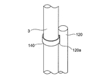
- the mounting portion 120 is a portion that is mounted along the left tube portion 3a or the right tube portion 3b in the same manner as the mounting portion 20, but the structure is different. That is, the mounting portion 20 is bent so that it can be mounted on the left tube portion 3a or the right tube portion 3b so as to be hooked from the inside of the region X, whereas the mounting portion 120 extends linearly. It differs in that it has a shape and is a structure that is mounted to the left tube portion 3a or the right tube portion 3b using the mounting member 130.
- the mounting portion 120 has a length that reaches the position on the distal end side beyond the portion covered with the connecting tube 4 in the left tube portion 3a or the right tube portion 3b in the mounted state on the stethoscope 1.
- the mounting portion 120 is mounted to the left tube portion 3a or the right tube portion 3b by the mounting member 130 at a position on the distal end side beyond the region covered with the connecting tube 4 in the left tube portion 3a or the right tube portion 3b.
- the mounting member 130 is formed of, for example, a ring formed of a wire or the like, or an annular body such as a binding band or a cylindrical member, and includes the left tube portion 3a or the right tube portion 3b, and along this. It mounts
- the operation unit 122 of the operation piece 112 exhibits the same function although there is a difference in shape from the operation unit 22 constituting the stethoscope attachment 10 of the first embodiment described above. That is, the operation unit 122 is provided on the operation piece 112 on the side opposite to the mounting unit 120 and can be configured so that the user can put his / her finger on the operation.
- the hinge portion 118 is provided between the mounting portions 120 and 120 and the operation portions 122 and 122 constituting the left operation piece 114 and the right operation piece 116.
- the hinge part 118 is connected so that the left operation piece 114 and the right operation piece 116 can be opened and closed.
- the hinge portion 118 is a support shaft 124 made of a combination of bolts and nuts in a hole-like portion formed by looping the wire rods forming the left operation piece 114 and the right operation piece 116. It is set as the structure which inserted.
- the operation portions 122 and 122 are pinched to reduce the distance between the two, thereby the interval between the operation portions 120 and 120 of the left operation piece 114 and the right operation piece 116.
- An operation (expansion operation) for expanding the file can be performed.
- the interval between the left tube portion 3a and the right tube portion 3b can be expanded.
- interval of the left pipe part 3a and the right pipe part 3b can be returned to the state which is not applying external force by loosening the force which grasps the operation parts 122 and 122.
- the stethoscope attachment 100 a user such as a doctor can attach and detach the stethoscope 1 with one hand. Also, the above-described stethoscope attachment 100 can be used by being attached to any stethoscope 1 selected by a doctor or the like.
- the mounting portion 120 is attached to the left tube portion 3a or the right tube using the mounting portion 130 at a position on the distal end side of the left tube portion 3a or the right tube portion 3b beyond the region covered by the connection tube 4. It is attached to the tube portion 3b. Therefore, the mounting portion 120 is in contact with a portion where the left tube portion 3a or the right tube portion 3b is exposed, and the sliding resistance at the mounting position is smaller than that of the above-described stethoscope attachment 10. Therefore, the mounting portion 120 can easily slide along the left tube portion 3a or the right tube portion 3b.
- the expansion operation for making the ear canal 3 into an expanded state can be performed more easily.
- FIG. 5 shows another example of the attachment 201 for the stethoscope of the present invention, and is a front view before assembly.
- the whole is made of plastic.
- the left operation piece 202 and the left operation portion 203 are integrated, the right operation piece 204 and the left operation portion 205 are integrated, and a central through portion 206 is provided in each.
- the shaft is rotatably inserted into the through hole of the through portion 206 and stopped.
- FIG. 6 shows a combination of the penetrating part 206, which is rotatable about the shaft.
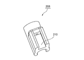
- a gripping tool 208 that can be fitted and fixed to the ear canal 3 of the stethoscope is fixed to the distal end portion 207 of the operation piece.
- the ear canal 3 is fitted into the recess 209 of the gripping tool 208.
- the connecting pipe 4 may be fitted depending on the size of the recess 209.
- the anti-slip process may be applied to the recess 209 of the gripping tool 208.
- a slip prevention tool other than the gripping tool 208 may be fixed to the ear canal 3.
- the slip prevention tool may be tightened by providing a screw or the like.
- FIG. 7 is a perspective view of the gripping tool 208 of FIG.
- a recess 210 into which the tip 207 is inserted is provided, and a recess 209 is provided on the opposite side.
- This gripping tool 208 facilitates fixation to the ear canal.
- an insertion hole 120 a is provided in the mounting portion 120, and an annular member 140 is prepared similarly to the mounting member 130. Then, the annular member 140 is inserted into the insertion hole 120a, and the annular member 140 is mounted so as to surround the left tube portion 3a or the right tube portion 3b. As a result, the mounting portion 120 can be mounted to the left tube portion 3a or the right tube portion 3b more reliably.
- a cover made of a flexible member such as a rubber body may be mounted on the surface.
- the attachment for a stethoscope of the present invention can be used for any existing stethoscope selected arbitrarily.
Abstract
In the past, there had been a problem in that when using a stethoscope, it had been necessary to interrupt work and mount the stethoscope using both hands, resulting in poor work efficiency. Additionally, when it is necessary to repeatedly mount and unmount the stethoscope for such as a group examination, for example, it had been necessary to continuously carry out an operation of extending auditory tubes, which is complicated. The present invention addresses these problems by providing a stethoscope attachment formed from mounting parts (20) which may be mounted upon both auditory tubes (3), and manipulation parts (22) for manipulating the mounting parts (20). The opening and closing of the mounting parts (20) by the opening and closing of the manipulation parts (22) is derived from the manipulation parts (22) and the mounting parts (20) being connected by a fulcrum so as to be able to revolve.
Description
本発明は、聴診器に装着される聴診器用アタッチメントに関する。
The present invention relates to an attachment for a stethoscope attached to a stethoscope.
従来、医師や看護師等が使用する聴診器として、聴診音を検出するための集音部と、使用者の左右の耳に挿入可能なように左管部及び右管部に分岐された耳管とを有し、両者の間をゴム管等の接続管を用いて接続したものが提供されている。このような聴診器においては、使用者である医師等が聴診器を装着する際に、自身の弾性力によって互いに近接した状態にある耳管に対し、左管部と右管部との間隔を拡張する方向に外力を加える操作(拡張操作)が必要となる。そのため、聴診器を装着するためには、使用者である医師等の両手を用いる必要がある。
Conventionally, as a stethoscope used by doctors, nurses, etc., a sound collection unit for detecting auscultation sounds and an ear branched into a left tube unit and a right tube unit so as to be inserted into the left and right ears of the user There are pipes that are connected to each other using a connecting pipe such as a rubber pipe. In such a stethoscope, when a doctor who is a user wears the stethoscope, the interval between the left tube portion and the right tube portion is set with respect to the ear canal that is close to each other by its own elastic force. An operation for applying an external force in the extending direction (expansion operation) is required. Therefore, in order to wear a stethoscope, it is necessary to use both hands of a user, such as a doctor.
ここで、実際の医療現場においては、様々な作業を行う必要があるにもかかわらず、聴診器を用いる場合には一旦作業を停止し、両手を用いて装着する必要があり、作業効率が悪いという問題がある。また、例えば集団検診等のために聴診器の着脱を繰り返さねばならないような場合には、耳管を拡張させる動作を何度も連続して実施する必要があり、煩雑である。従って、片手で他の作業をしつつ、もう一方の手だけで聴診器を着脱可能とすることができれば、医療現場におけるさらなる作業効率の向上が見込める。かかる観点から検討すると、例えば下記特許文献1に開示されているような検診用顎関節聴診器のようなものが有効であると考えられる。
Here, in an actual medical field, although it is necessary to perform various operations, when using a stethoscope, it is necessary to stop the operation and wear it with both hands, which is inefficient. There is a problem. In addition, for example, when it is necessary to repeat attachment and detachment of a stethoscope for a group examination or the like, it is necessary to repeatedly perform an operation of expanding the ear canal, which is complicated. Therefore, if the stethoscope can be attached / detached only with the other hand while performing other work with one hand, further improvement in work efficiency in the medical field can be expected. Considering this point of view, for example, a temporomandibular joint stethoscope for medical examination as disclosed in Patent Document 1 below is considered effective.
ここで、上述した特許文献1に開示されている検診用顎関節聴診器は、検診者に装着する耳管部にバネ式把持器を設けることで、耳管部を片手で検診者が装着できるもの(特開2013-192919号公報の請求項4参照)とされているものの、当該発明におけるバネ式把持器は耳管部に対して後付けできるようなものではない。また、当該発明におけるバネ式把持器においては、既存の聴診器に対して後付けすることが想定されておらず、何らの配慮がなされていない。そのため、医師等が普段使用しているような既存の聴診器に対して装着することができず、上手く使用することができない。聴診器は、医師等の身体に装着して使用するものであるため、医師等の好みや用途によって使い分けることが考えられる。従って、既存の聴診器等、任意の聴診器に対して取り付けて問題なく使用可能なアタッチメントの提供が強く望まれている。
Here, the temporomandibular joint stethoscope for screening disclosed in Patent Document 1 described above can be mounted on the ear canal by one hand by providing the spring-type gripper on the ear canal mounted on the examiner. Although it is said that it is a thing (refer Claim 4 of Unexamined-Japanese-Patent No. 2013-192919), the spring type gripper in the said invention cannot be retrofitted with respect to an ear canal part. Moreover, in the spring type grasper in the said invention, it is not assumed that it retrofits with respect to the existing stethoscope, and no consideration is made. For this reason, it cannot be attached to an existing stethoscope that is usually used by doctors and the like, and cannot be used well. Since the stethoscope is used by being attached to the body of a doctor or the like, it is conceivable that the stethoscope is properly used depending on the preference or application of the doctor or the like. Therefore, it is strongly desired to provide an attachment that can be used without any problem by being attached to an arbitrary stethoscope such as an existing stethoscope.
また、特許文献2に記載された聴診器拡張器は、その図1から見てあきらかなように、第1部材と第2部材が大きな円状に形成され、これが、後述する接続管の分岐部より上方に突出している。これでは、使用者の顎に当たり邪魔になる。これを避けようとすると、接続管の分岐部を下方に大きく下げなければならず、市販の聴診器は使用できない。
Further, in the stethoscope dilator described in Patent Document 2, as clearly seen from FIG. 1, the first member and the second member are formed in a large circular shape, and this is a branch portion of the connecting pipe described later. It protrudes further upward. This hits the user's chin and gets in the way. If it is going to avoid this, the branch part of a connecting pipe must be greatly lowered below, and a commercially available stethoscope cannot be used.
本発明は前述したとおり、通常の、医師が自己の好みや用途で選択した聴診器が使用できるものである。
As described above, the present invention can use a normal stethoscope selected by a doctor according to his / her own preference and application.
上述した課題を解決すべく、本発明は任意の聴診器に対しても取り付けて問題なく耳管の操作が可能となる聴診器用アタッチメントの提供を目的とした。
In order to solve the above-described problems, an object of the present invention is to provide an attachment for a stethoscope that can be attached to any stethoscope and can be operated with no problem.
以上のような状況に鑑み、本発明者は鋭意研究の結果、本発明聴診器用アタッチメントを完成したものであり、その特徴とするところは、聴診音を検出するための集音部2と、使用者の左右の耳に挿入可能なように分岐された左管部3a及び右管部3bを有する耳管3と、前記集音部2と前記左管部3a及び前記右管部3bとを繋ぐ接続管4とを備え、前記接続管4の弾性力により前記接続管を介して前記左管部3a及び前記右管部3bが互いに近接する方向に付勢されており、前記左管部3a及び前記右管部3b、又は前記接続管4の前記耳管3側の端部で被覆された前記左管部3aの一端部及び前記右管部3bの一端部に対して前記付勢方向とは逆方向に外力を加えることにより、前記左管部3a及び前記右管部3bの間隔が拡張するように弾性変形させた拡張状態とすることが可能な聴診器1に装着される聴診器用アタッチメント10であって、
該両耳管3に装着可能な装着部20、及び該装着部20を操作するための操作部22からなり、
該装着部20は、該操作部22の開閉によって、開閉されるようは、該操作部22及び該装着部20が可回転のヒンジ部18によって接続され、且つ、該ヒンジ部は、聴診器に装着された際、前記左管部3a及び前記右管部3bと前記接続管4とで囲まれた領域外に位置する点にある。 In view of the situation as described above, the present inventor has completed the attachment for the stethoscope of the present invention as a result of earnest research, and the feature thereof is that thesound collecting unit 2 for detecting the auscultatory sound and the use The ear tube 3 having the left tube portion 3a and the right tube portion 3b branched so as to be inserted into the left and right ears of the person, and the sound collecting portion 2, the left tube portion 3a, and the right tube portion 3b. A connecting pipe 4, and the left pipe part 3 a and the right pipe part 3 b are biased in a direction close to each other via the connecting pipe by the elastic force of the connecting pipe 4, and the left pipe part 3 a and What is the biasing direction with respect to one end of the left tube 3a and one end of the right tube 3b covered with the end of the right tube 3b or the connecting tube 4 on the ear tube 3 side? By applying an external force in the opposite direction, the interval between the left tube portion 3a and the right tube portion 3b is expanded. A stethoscope dexterity attachment 10 mounted on the stethoscope 1, which can be an expanded state of being elastically deformed,
Amounting unit 20 that can be mounted on the ear canal 3 and an operation unit 22 for operating the mounting unit 20;
Theoperating unit 22 and the mounting unit 20 are connected by a rotatable hinge unit 18 so that the mounting unit 20 is opened and closed by opening and closing the operating unit 22, and the hinge unit is connected to a stethoscope. When mounted, it is located outside the region surrounded by the left tube portion 3a, the right tube portion 3b, and the connection tube 4.
該両耳管3に装着可能な装着部20、及び該装着部20を操作するための操作部22からなり、
該装着部20は、該操作部22の開閉によって、開閉されるようは、該操作部22及び該装着部20が可回転のヒンジ部18によって接続され、且つ、該ヒンジ部は、聴診器に装着された際、前記左管部3a及び前記右管部3bと前記接続管4とで囲まれた領域外に位置する点にある。 In view of the situation as described above, the present inventor has completed the attachment for the stethoscope of the present invention as a result of earnest research, and the feature thereof is that the
A
The
本発明の聴診器用アタッチメントは、左操作片及び右操作片の装着部をそれぞれ左管部及び右管部に対して自由に着脱することができる。そのため、本発明の聴診器用アタッチメントは、例えば医師等の好みに応じて選択された任意の聴診器に対して取り付けて使用することができる。また、本発明の聴診器用アタッチメントは、左操作片及び右操作片の操作部同士を近接させる操作を実施するだけで、左操作片の装着部及び右操作片の装着部の動作に連動させて左管部及び右管部の間隔を拡張させることができる。そのため、本発明の聴診器用アタッチメントを用いることにより、医師等は、片手のみを用いた操作で耳管を拡張させて耳に装着することが可能となる。従って、本発明の聴診器用アタッチメントを用いることにより、医師等の作業効率を格段に向上させることができる。
The attachment for a stethoscope of the present invention can freely attach and detach the left operating piece and the right operating piece with respect to the left tube portion and the right tube portion, respectively. Therefore, the attachment for stethoscopes of this invention can be attached and used with respect to the arbitrary stethoscopes selected according to liking of a doctor etc., for example. In addition, the attachment for the stethoscope of the present invention can be operated in conjunction with the operation of the left operating piece mounting portion and the right operating piece mounting portion only by performing an operation of bringing the operating portions of the left operating piece and the right operating piece close to each other. The distance between the left tube portion and the right tube portion can be expanded. Therefore, by using the stethoscope attachment of the present invention, a doctor or the like can expand the ear canal and attach it to the ear by an operation using only one hand. Therefore, by using the attachment for a stethoscope of the present invention, the work efficiency of a doctor or the like can be significantly improved.
また、本発明の聴診器用アタッチメントは、前記左操作片及び前記右操作片の前記装着部のいずれか一方又は双方が、前記左管部又は前記右管部に沿って摺動可能なように装着可能なものであることが望ましい。
Further, the attachment for a stethoscope of the present invention is mounted so that either one or both of the left operating piece and the mounting portion of the right operating piece can slide along the left tube portion or the right tube portion. It is desirable to be possible.
かかる構成とした場合、拡張操作を行う際に左管部又は右管部に沿って装着部を摺動させ、耳管の左管部及び右管部の間隔を広げるために要する負荷を低減させることができる。従って、本発明によれば、耳管を拡張状態とするための拡張操作をより一層軽快に行うことが可能な聴診器用アタッチメントを提供することができる。
In such a configuration, when performing the expansion operation, the mounting portion is slid along the left tube portion or the right tube portion, and the load required to widen the interval between the left tube portion and the right tube portion of the ear canal is reduced. be able to. Therefore, according to the present invention, it is possible to provide an attachment for a stethoscope that can perform an expansion operation for making the ear canal an expanded state even more easily.
上述した本発明の聴診器用アタッチメントは、前記左操作片及び前記右操作片の前記装着部のいずれか一方又は双方が、前記左管部又は前記右管部と共に外周を取り巻くように装着された装着部材によって装着されているものとすることが可能である。
The attachment for a stethoscope of the present invention described above is mounted such that one or both of the left operating piece and the mounting portion of the right operating piece are mounted so as to surround an outer periphery together with the left tube portion or the right tube portion. It can be attached by a member.
かかる構成によれば、左操作片や右操作片による拡張操作に連動させて左管部や右管部を確実に拡張状態とさせることが可能な聴診器用アタッチメントを提供できる。
According to such a configuration, it is possible to provide an attachment for a stethoscope that can reliably bring the left tube portion and the right tube portion into an expanded state in conjunction with the expansion operation using the left operation piece and the right operation piece.
上述した本発明の聴診器用アタッチメントは、前記左操作片及び前記右操作片の前記装着部のいずれか一方又は双方の前記装着部を前記左管部又は前記右管部に対して装着するための環状部材を有し、前記装着部に、前記環状部材を挿通可能な挿通部が設けられており、前記挿通部に挿通された前記環状部材を前記左管部又は前記右管部を取り巻くように装着することにより、前記左操作片及び前記右操作片の前記装着部のいずれか一方又は双方が、前記左管部又は前記右管部に対して装着されるものであってもよい。
The attachment for a stethoscope of the present invention described above is for mounting the mounting portion of one or both of the left operating piece and the mounting portion of the right operating piece to the left tube portion or the right tube portion. There is an annular member, and the mounting portion is provided with an insertion portion through which the annular member can be inserted, and the annular member inserted through the insertion portion surrounds the left tube portion or the right tube portion. By mounting, either one or both of the mounting portions of the left operation piece and the right operation piece may be mounted on the left tube portion or the right tube portion.
本発明でいうヒンジ部とは、部材が回転可能に接続されている部分を言い、その形状や構造は特に限定しない。単に、交差する部材に貫通孔を設けて、軸を入れただけのものでもよい。
In the present invention, the hinge portion refers to a portion where the members are rotatably connected, and the shape and structure are not particularly limited. It is possible to simply provide a through hole in a crossing member and insert a shaft.
本発明の大きなポイントは、ヒンジ部が、聴診器に装着された際、前記左管部3a及び前記右管部3bと前記接続管4とで囲まれた領域の外に位置する点である。即ち、操作部を操作してその幅を狭めると、ヒンジ部は上方に移動するが、上方に移動した位置でも、この領域の外に位置しているのである。
これによって、使用者の顎や首に当たらず邪魔にならない。 A major point of the present invention is that the hinge portion is located outside the region surrounded by theleft tube portion 3a, the right tube portion 3b, and the connection tube 4 when mounted on a stethoscope. That is, when the operating portion is operated and the width thereof is narrowed, the hinge portion moves upward, but the position moved upward is also located outside this region.
As a result, it does not hit the user's chin or neck and does not get in the way.
これによって、使用者の顎や首に当たらず邪魔にならない。 A major point of the present invention is that the hinge portion is located outside the region surrounded by the
As a result, it does not hit the user's chin or neck and does not get in the way.
本発明のヒンジ部に、左右の操作片が一定以上狭くならないようなストッパーを設けてもよい。即ち、聴診器は自身の弾性力によって左右の操作片は互いに近接した状態になっている。それが必要以上に接近すると、拡張するときに引っかかることがあり手間がかかる。よって、必要以上(使用者の耳にきっちり嵌る以上に近く)に縮まらないように、ヒンジ部にストッパーを設けて、回転途中で係止するようにするのがよい。
A stopper may be provided on the hinge portion of the present invention so that the left and right operation pieces do not become narrower than a certain size. That is, the stethoscope is in a state where the left and right operation pieces are close to each other by its own elastic force. If it approaches more than necessary, it may become trapped when expanding, which is troublesome. Therefore, it is preferable to provide a stopper on the hinge portion so that it is locked during rotation so that it does not shrink more than necessary (closer than it fits tightly into the user's ear).
かかる構成とした場合、左操作片や右操作片を耳管の左管部や右管部に対してより一層確実に取り付けることが可能となる。これにより、拡張操作に伴う左操作片及や右操作片の動作に連動させて確実に左管部及び右管部の間隔を拡張させることが可能となる。従って、本発明によれば、耳管に対する取り付けをより一層確実なものとすると共に、拡張操作による耳管の拡張動作の確実性も向上させることができる。
In such a configuration, the left operation piece and the right operation piece can be more reliably attached to the left tube portion and the right tube portion of the ear canal. Thereby, it becomes possible to expand the space | interval of a left pipe part and a right pipe part reliably in response to the operation | movement of the left operation piece and right operation piece accompanying expansion operation. Therefore, according to the present invention, the attachment to the ear canal can be further ensured, and the reliability of the expansion operation of the ear canal by the expansion operation can be improved.
本発明によれば、任意の聴診器に対しても取り付けて問題なく耳管を操作可能な聴診器用アタッチメントを提供することができる。
According to the present invention, it is possible to provide an attachment for a stethoscope that can be attached to any stethoscope and can operate the ear canal without any problem.
(第1実施形態)
以下、本発明の第1実施形態に係る聴診器用アタッチメント10について説明する。なお、以下の説明においては、本実施形態の聴診器用アタッチメント10の説明に先立ち、まず取り付け対象である聴診器1の概略構成について説明する。なお、以下の説明においては、特に断りのない限り、図1において示すように聴診器1を配置した状態を基準として、左右及び表裏の位置関係を用いて説明する。 (First embodiment)
Hereinafter, theattachment 10 for stethoscopes which concerns on 1st Embodiment of this invention is demonstrated. In the following description, prior to the description of the stethoscope attachment 10 of the present embodiment, a schematic configuration of the stethoscope 1 that is an attachment target will be described first. In the following description, unless otherwise specified, description will be made using the positional relationship between the left and right and front and back with reference to the state in which the stethoscope 1 is disposed as shown in FIG.
以下、本発明の第1実施形態に係る聴診器用アタッチメント10について説明する。なお、以下の説明においては、本実施形態の聴診器用アタッチメント10の説明に先立ち、まず取り付け対象である聴診器1の概略構成について説明する。なお、以下の説明においては、特に断りのない限り、図1において示すように聴診器1を配置した状態を基準として、左右及び表裏の位置関係を用いて説明する。 (First embodiment)
Hereinafter, the
(聴診器1の概略構成について)
図1に示すように、聴診器1は、集音部2と耳管3と接続管4とを有する。集音部2は、人体等の聴診音の集音対象に対して接触させることにより聴診音を検出するために設けられた部分である。 (About the schematic configuration of the stethoscope 1)
As shown in FIG. 1, thestethoscope 1 includes a sound collection unit 2, an ear canal 3, and a connection tube 4. The sound collection unit 2 is a portion provided for detecting auscultation sound by bringing it into contact with a sound collection target of auscultation sound such as a human body.
図1に示すように、聴診器1は、集音部2と耳管3と接続管4とを有する。集音部2は、人体等の聴診音の集音対象に対して接触させることにより聴診音を検出するために設けられた部分である。 (About the schematic configuration of the stethoscope 1)
As shown in FIG. 1, the
耳管3は、金属管等からなる管状体によって構成されており、医師等の使用者の左右の耳に挿入可能なように屈曲させた形状とされている。耳管3は、左管部3a及び右管部3bに分岐されており、その先端側の使用者の耳に挿入される部分にイヤーピース3c、3cが取り付けられている。耳管3は、自身の弾性力により左管部3a及び右管部3bが互いに近接する方向(図1における矢印F方向)に付勢されている。耳管3は、前述した付勢方向とは逆方向(図1における矢印A方向)に外力を加えることにより、左管部3a及び右管部3bの間隔を拡張させた状態(拡張状態)とすることができる。聴診器1の使用者は、耳管3を拡張状態として自身の両耳の間隔以上に拡げた状態とすることで、イヤーピース3c、3cを両耳に挿入して装着することができる。
The ear canal 3 is formed of a tubular body made of a metal tube or the like, and is bent so that it can be inserted into the left and right ears of a user such as a doctor. The ear canal 3 is branched into a left tube portion 3a and a right tube portion 3b, and ear pieces 3c and 3c are attached to a portion to be inserted into the user's ear on the distal end side. The eustachian tube 3 is biased in the direction in which the left tube portion 3a and the right tube portion 3b approach each other (in the direction of arrow F in FIG. 1) by its own elastic force. The ear canal 3 is in a state (expanded state) in which the interval between the left tube portion 3a and the right tube portion 3b is expanded by applying an external force in a direction opposite to the biasing direction described above (direction of arrow A in FIG. 1). can do. The user of the stethoscope 1 can insert and wear the earpieces 3c and 3c into both ears by setting the ear canal 3 to be in an expanded state and extending beyond the distance between his / her ears.
接続管4は、集音部2及び耳管3を繋ぐための配管である。接続管4は、ゴム管や塩化ビニルなどの樹脂管によって構成された屈曲性の高い管によって構成されている。接続管4は、集音部2から耳管3の左管部3a及び右管部3bに分岐するまでの間が、1本の管によって構成されたものや、1本の管で構成された内部に隔壁が設けられたもの、2本の管によって構成されたもの等、適宜のものとすることができる。接続管4において耳管3側の端部は、一部が耳管3をなす左管部3a及び右管部3bの基端側(イヤーピース3c、3c側とは反対)の部分を被覆している。
The connection pipe 4 is a pipe for connecting the sound collection unit 2 and the ear canal 3. The connecting pipe 4 is constituted by a highly flexible pipe made of a rubber pipe or a resin pipe such as vinyl chloride. The connection tube 4 is constituted by one tube or one tube until it branches from the sound collecting portion 2 to the left tube portion 3a and the right tube portion 3b of the ear tube 3. It is possible to use appropriate ones such as one provided with a partition inside, one constituted by two pipes, and the like. In the connection tube 4, the end portion on the ear tube 3 side partially covers the portions of the left tube portion 3 a and the right tube portion 3 b on the proximal end side (opposite to the ear pieces 3 c and 3 c side). Yes.
(聴診器用アタッチメント10について)
図1に示すように聴診器用アタッチメント10は、上述した聴診器1に装着され、耳管3を拡張状態とするための操作を可能とするためのアタッチメントである。図1及び図2に示すように、聴診器用アタッチメント10は、一対の操作片12(以下、必要に応じてそれぞれを左操作片14及び右操作片16とも称す)と、ヒンジ部18とを有する。 (About the stethoscope attachment 10)
As shown in FIG. 1, thestethoscope attachment 10 is an attachment that is attached to the above-described stethoscope 1 and enables an operation for bringing the ear canal 3 into an expanded state. As shown in FIGS. 1 and 2, the stethoscope attachment 10 includes a pair of operation pieces 12 (hereinafter also referred to as a left operation piece 14 and a right operation piece 16 as necessary) and a hinge portion 18. .
図1に示すように聴診器用アタッチメント10は、上述した聴診器1に装着され、耳管3を拡張状態とするための操作を可能とするためのアタッチメントである。図1及び図2に示すように、聴診器用アタッチメント10は、一対の操作片12(以下、必要に応じてそれぞれを左操作片14及び右操作片16とも称す)と、ヒンジ部18とを有する。 (About the stethoscope attachment 10)
As shown in FIG. 1, the
操作片12(左操作片14及び右操作片16)は、一端側に装着部20を有し、他端側に操作部22を備えた構造とされている。操作片12は、針金等の線材を屈曲形状に加工することで作成されたものである。左操作片14及び右操作片16は、それぞれ略左右対称の形状とされている。
The operation piece 12 (the left operation piece 14 and the right operation piece 16) has a mounting part 20 on one end side and an operation part 22 on the other end side. The operation piece 12 is created by processing a wire such as a wire into a bent shape. The left operation piece 14 and the right operation piece 16 are substantially symmetrical in shape.
左操作片14及び右操作片16は、それぞれ装着部20、20を左管部3a及び右管部3bに対して着脱可能とされている。具体的には、装着部20は、左管部3a及び右管部3bの外周に沿うように湾曲したフック状の形状とされており、左管部3a及び右管部3bの間(内側)に形成された領域X側から外側に向けて引っかけるようにして左管部3a及び右管部3bに対して装着可能とされている。本実施形態では、左管部3a及び右管部3bの基端側においてゴム等からなる接続管4によって被覆されている部分に左操作片14及び右操作片16の装着部20、20が装着されている。そのため、装着部20、20は、接続管4との間に発生する摩擦力によって容易に脱落しないように装着されている。
The left operation piece 14 and the right operation piece 16 are configured such that the mounting portions 20 and 20 can be attached to and detached from the left tube portion 3a and the right tube portion 3b, respectively. Specifically, the mounting portion 20 has a hook-like shape that is curved along the outer periphery of the left tube portion 3a and the right tube portion 3b, and is between the left tube portion 3a and the right tube portion 3b (inside). It can be attached to the left tube portion 3a and the right tube portion 3b so as to be hooked outward from the region X side formed in FIG. In the present embodiment, the mounting portions 20 and 20 of the left operation piece 14 and the right operation piece 16 are mounted on the portions covered by the connecting pipe 4 made of rubber or the like on the base end side of the left tube portion 3a and the right tube portion 3b. Has been. Therefore, the mounting portions 20 and 20 are mounted so as not to easily fall off due to a frictional force generated between the connecting portions 4 and 20.
操作部22は、操作片12において装着部20とは反対側に設けられている。操作部22は、聴診器用アタッチメント10の操作に際して使用者が指を掛ける部分である。具体的には、左操作片14及び右操作片16の操作部22、22のうち一方には、使用者の親指等の指が掛けられ、他方には人差し指等の指が掛けられる。そして、図1において矢印Bで示すように左操作片14及び右操作片16の操作部22、22に引っかけた指同士が近接するように摘まむ動作を行うことにより、図1において矢印Aで示す方向に左操作片14及び右操作片16を動作させる操作を実行できる。
The operation unit 22 is provided on the operation piece 12 on the side opposite to the mounting unit 20. The operation unit 22 is a part where the user places a finger when operating the stethoscope attachment 10. Specifically, a finger such as a user's thumb is hung on one of the operation portions 22 and 22 of the left operation piece 14 and the right operation piece 16, and a finger such as an index finger is hung on the other. Then, as shown by an arrow B in FIG. 1, by performing an operation of picking the fingers hooked on the operation portions 22 and 22 of the left operation piece 14 and the right operation piece 16 close to each other, an arrow A in FIG. An operation of operating the left operation piece 14 and the right operation piece 16 in the direction shown can be executed.
ヒンジ部18は、左操作片14及び右操作片16の装着部20、20と操作部22、22との中間に設けられており、左操作片14及び右操作片16を開閉操作可能なように接続する部分である。本実施形態では、左操作片14及び右操作片16をなす線材をループさせることによって形成された孔状の部位にボルト及びナットの組み合わせ等からなる支軸24を挿通することによりヒンジ部18が形成されている。また、本実施形態では、ヒンジ部18が、聴診器1への装着状態における表側及び裏側の双方に設けられている。
The hinge portion 18 is provided between the mounting portions 20 and 20 of the left operation piece 14 and the right operation piece 16 and the operation portions 22 and 22 so that the left operation piece 14 and the right operation piece 16 can be opened and closed. This is the part that connects to In the present embodiment, the hinge portion 18 is inserted by inserting the support shaft 24 made of a combination of a bolt and a nut into a hole-like portion formed by looping the wire rods forming the left operation piece 14 and the right operation piece 16. Is formed. Moreover, in this embodiment, the hinge part 18 is provided in both the front side and back side in the mounting state to the stethoscope 1. FIG.
聴診器用アタッチメント10は、図1において矢印Bで示すように操作部22、22を摘まんで左操作片14の操作部22、及び右操作片16の操作部22を近接させることにより、同図において矢印Aで示すように左操作片14の装着部20及び右操作片16の装着部20の間隔を拡張させることができる。これにより、左管部3a及び右管部3bに対して外力を作用させ、両者の間隔を拡張させる操作(拡張操作)を行うことができる。従って、聴診器用アタッチメント10を用いれば、医師等の使用者は、片手のみを用いた操作で耳管3を拡張させて耳に装着することが可能となる。また、操作部22、22を摘まむのをやめると、耳管3自身の弾性力によって耳管3が元の状態に戻る。そのため、拡張操作によって矢印A方向に拡張させた耳管3を使用者の耳にあてがった後、操作部22、22を摘まむのを止めることで、聴診器1の装着を完了させることができる。また、使用者が聴診器1を外したい場合についても、操作部22、22を摘まんで耳管3を拡張させるだけの操作で聴診器1を外すことができる。
As shown by the arrow B in FIG. 1, the stethoscope attachment 10 holds the operation portions 22, 22 and brings the operation portion 22 of the left operation piece 14 and the operation portion 22 of the right operation piece 16 close to each other in FIG. As indicated by an arrow A, the interval between the mounting portion 20 of the left operation piece 14 and the mounting portion 20 of the right operation piece 16 can be expanded. Thereby, an external force can be applied to the left tube portion 3a and the right tube portion 3b, and an operation (expansion operation) for expanding the distance between the two can be performed. Therefore, by using the stethoscope attachment 10, a user such as a doctor can expand the ear canal 3 and attach it to the ear by an operation using only one hand. When the operation parts 22 and 22 are stopped, the ear canal 3 returns to the original state by the elastic force of the ear canal 3 itself. Therefore, after the eustachian tube 3 expanded in the direction of the arrow A by the expansion operation is applied to the user's ear, it is possible to complete the wearing of the stethoscope 1 by stopping the operation portions 22 and 22 from being picked. . Further, when the user wants to remove the stethoscope 1, the stethoscope 1 can be removed by an operation of simply grasping the operation units 22 and 22 and expanding the ear canal 3.
上述したように、聴診器用アタッチメント10は、操作部22、22の操作を片手で行うだけで聴診器1の着脱を容易に行うことができる。そのため、聴診器用アタッチメント10を用いることにより、医師等の作業効率を格段に向上させることができる。
As described above, the stethoscope attachment 10 can easily attach and detach the stethoscope 1 only by operating the operation units 22 and 22 with one hand. Therefore, by using the attachment 10 for a stethoscope, the working efficiency of a doctor or the like can be significantly improved.
また、上述した聴診器用アタッチメント10は、医師等が選択した任意の聴診器1に対して装着して使用することができる。従って、聴診器用アタッチメント10によれば、医師等の好みや用途等によって選択された様々なタイプの聴診器1について、着脱を片手で行えるものとすることができる。
Further, the above-described stethoscope attachment 10 can be used by being attached to any stethoscope 1 selected by a doctor or the like. Therefore, according to the attachment 10 for stethoscopes, it is possible to attach and detach various types of stethoscopes 1 selected according to the preference or use of a doctor or the like with one hand.
(第2実施形態)
以下、本発明の第2実施形態に係る聴診器用アタッチメント100について、上述した聴診器1に装着する例を挙げつつ説明する。なお、本実施形態の聴診器用アタッチメント100において、上述した第1実施形態の聴診器用アタッチメント10と共通する構成については、第1実施形態において各構成に付した符号に100を付加したものを符号として用い、詳細の説明については省略する。 (Second Embodiment)
Hereinafter, anattachment 100 for a stethoscope according to a second embodiment of the present invention will be described with reference to an example of mounting on the stethoscope 1 described above. In addition, in the attachment 100 for stethoscopes of this embodiment, about the structure which is common with the attachment 10 for stethoscopes of 1st Embodiment mentioned above, what added 100 to the code | symbol attached | subjected to each structure in 1st Embodiment as a code | symbol The detailed description will be omitted.
以下、本発明の第2実施形態に係る聴診器用アタッチメント100について、上述した聴診器1に装着する例を挙げつつ説明する。なお、本実施形態の聴診器用アタッチメント100において、上述した第1実施形態の聴診器用アタッチメント10と共通する構成については、第1実施形態において各構成に付した符号に100を付加したものを符号として用い、詳細の説明については省略する。 (Second Embodiment)
Hereinafter, an
聴診器用アタッチメント100は、上述した聴診器用アタッチメント10と同様に聴診器1に装着され、耳管3を拡張状態とするための操作を可能とするためのアタッチメントである。図3に示すように、聴診器用アタッチメント10は、一対の操作片112(以下、必要に応じてそれぞれを左操作片114及び右操作片116とも称す)と、ヒンジ部118とを有する。また、聴診器用アタッチメント100は、左操作片114及び右操作片116を耳管3の左管部3a及び右管部3bに対して装着するための装着部材130を備えている点において、上述した聴診器用アタッチメント10と構成が相違している。
The stethoscope attachment 100 is an attachment that is attached to the stethoscope 1 in the same manner as the above-described stethoscope attachment 10 and enables an operation for bringing the ear canal 3 into an expanded state. As shown in FIG. 3, the stethoscope attachment 10 includes a pair of operation pieces 112 (hereinafter also referred to as a left operation piece 114 and a right operation piece 116 as necessary) and a hinge portion 118. Further, the attachment 100 for the stethoscope includes the mounting member 130 for mounting the left operation piece 114 and the right operation piece 116 to the left tube portion 3a and the right tube portion 3b of the ear canal 3 as described above. The configuration is different from that of the stethoscope attachment 10.
操作片112(左操作片114及び右操作片116)は、一端側に装着部120を有し、他端側に操作部122を備えている。操作片112は、針金等の線材を加工することで作成されている。左操作片114及び右操作片116は、それぞれ略左右対称の形状とされている。
The operation piece 112 (the left operation piece 114 and the right operation piece 116) has a mounting portion 120 on one end side and an operation portion 122 on the other end side. The operation piece 112 is created by processing a wire such as a wire. The left operation piece 114 and the right operation piece 116 are substantially symmetrical in shape.
操作片112は、操作部120の構成が上述した第1実施形態の聴診器用アタッチメント10を構成する装着部20と相違している。具体的には、装着部120は、装着部20と同様に左管部3aあるいは右管部3bに沿って装着される部分であるが構造が相違している。すなわち、装着部20が左管部3aあるいは右管部3bに対して領域Xの内側から引っ掛けるようにして装着可能なように屈曲させた形状であるのに対し、装着部120は直線状に伸びる形状とされており、装着部材130を用いて左管部3aあるいは右管部3bに対して装着される構造である点において相違している。
The operation piece 112 is different in the configuration of the operation unit 120 from the mounting unit 20 constituting the stethoscope attachment 10 of the first embodiment described above. Specifically, the mounting portion 120 is a portion that is mounted along the left tube portion 3a or the right tube portion 3b in the same manner as the mounting portion 20, but the structure is different. That is, the mounting portion 20 is bent so that it can be mounted on the left tube portion 3a or the right tube portion 3b so as to be hooked from the inside of the region X, whereas the mounting portion 120 extends linearly. It differs in that it has a shape and is a structure that is mounted to the left tube portion 3a or the right tube portion 3b using the mounting member 130.
装着部120は、聴診器1への装着状態において左管部3aあるいは右管部3bにおいて接続管4によって被覆されている部分を越えてさらに先端側の位置に到達する長さとされている。装着部120は、左管部3aあるいは右管部3bにおける接続管4による被覆領域を越えて先端側の位置において、装着部材130によって左管部3aあるいは右管部3bに対して装着されている。装着部材130は、例えば針金等を環状に形成したものや、結束バンド等の環状体や筒状の部材によって構成されるものであり、左管部3aあるいは右管部3b、及びこれに沿って配された装着部120の両者の外周を取り巻くように装着される。
The mounting portion 120 has a length that reaches the position on the distal end side beyond the portion covered with the connecting tube 4 in the left tube portion 3a or the right tube portion 3b in the mounted state on the stethoscope 1. The mounting portion 120 is mounted to the left tube portion 3a or the right tube portion 3b by the mounting member 130 at a position on the distal end side beyond the region covered with the connecting tube 4 in the left tube portion 3a or the right tube portion 3b. . The mounting member 130 is formed of, for example, a ring formed of a wire or the like, or an annular body such as a binding band or a cylindrical member, and includes the left tube portion 3a or the right tube portion 3b, and along this. It mounts | wears so that the outer periphery of both of the mounting | wearing part 120 arrange | positioned may be surrounded.
操作片112の操作部122は、上述した第一実施形態の聴診器用アタッチメント10を構成する操作部22と形状の差異はあるものの、同一の機能を発揮するものとされている。すなわち、操作部122は、操作片112において装着部120とは反対側に設けられており、使用者が操作に際して指を掛けることができる構成とされている。
The operation unit 122 of the operation piece 112 exhibits the same function although there is a difference in shape from the operation unit 22 constituting the stethoscope attachment 10 of the first embodiment described above. That is, the operation unit 122 is provided on the operation piece 112 on the side opposite to the mounting unit 120 and can be configured so that the user can put his / her finger on the operation.
ヒンジ部118は、左操作片114及び右操作片116を構成する装着部120、120と操作部122、122との中間に設けられている。ヒンジ部118は、左操作片114及び右操作片116を開閉操作可能なように接続している。ヒンジ部118は、上述したヒンジ部18と同様に、左操作片114及び右操作片116をなす線材をループさせることによって形成された孔状の部位にボルト及びナットの組み合わせ等からなる支軸124を挿通した構成とされている。
The hinge portion 118 is provided between the mounting portions 120 and 120 and the operation portions 122 and 122 constituting the left operation piece 114 and the right operation piece 116. The hinge part 118 is connected so that the left operation piece 114 and the right operation piece 116 can be opened and closed. As with the hinge portion 18 described above, the hinge portion 118 is a support shaft 124 made of a combination of bolts and nuts in a hole-like portion formed by looping the wire rods forming the left operation piece 114 and the right operation piece 116. It is set as the structure which inserted.
聴診器用アタッチメント100についても、上述した聴診器用アタッチメント10と同様に、操作部122、122を摘まんで両者の間隔を狭めることにより、左操作片114及び右操作片116の操作部120、120の間隔を拡張させる操作(拡張操作)を実施できる。拡張操作を実施することにより、左管部3a及び右管部3bの間隔を拡張させることができる。また、操作部122、122を摘まむ力を緩めることで、左管部3a及び右管部3bの間隔を外力を加えていない状態に戻すことができる。従って、聴診器用アタッチメント100を用いることによっても、医師等の使用者が片手で聴診器1を着脱することができる。また、上述した聴診器用アタッチメント100についても、医師等が選択した任意の聴診器1に対して装着して使用することができる。
As for the stethoscope attachment 100, similarly to the above-described stethoscope attachment 10, the operation portions 122 and 122 are pinched to reduce the distance between the two, thereby the interval between the operation portions 120 and 120 of the left operation piece 114 and the right operation piece 116. An operation (expansion operation) for expanding the file can be performed. By performing the expansion operation, the interval between the left tube portion 3a and the right tube portion 3b can be expanded. Moreover, the space | interval of the left pipe part 3a and the right pipe part 3b can be returned to the state which is not applying external force by loosening the force which grasps the operation parts 122 and 122. FIG. Therefore, by using the stethoscope attachment 100, a user such as a doctor can attach and detach the stethoscope 1 with one hand. Also, the above-described stethoscope attachment 100 can be used by being attached to any stethoscope 1 selected by a doctor or the like.
また、聴診器用アタッチメント100においては、左管部3aあるいは右管部3bにおける接続管4による被覆領域を越えて先端側の位置において、装着部130を用いて装着部120が左管部3aあるいは右管部3bに対して装着されている。そのため、装着部120は、左管部3aあるいは右管部3bが露出した部位において接触しており、上述した聴診器用アタッチメント10の場合に比べて装着位置における摺動抵抗が小さい。そのため、装着部120が、左管部3aあるいは右管部3bに沿って容易に摺動できる。このような構成とすることにより、拡張操作を行う際に操作部122、122を摘まむために必要とされる負荷を低減させることができる。従って、聴診器用アタッチメント100によれば、耳管3を拡張状態とするための拡張操作をより一層軽快に行うことができる。
In addition, in the attachment 100 for the stethoscope, the mounting portion 120 is attached to the left tube portion 3a or the right tube using the mounting portion 130 at a position on the distal end side of the left tube portion 3a or the right tube portion 3b beyond the region covered by the connection tube 4. It is attached to the tube portion 3b. Therefore, the mounting portion 120 is in contact with a portion where the left tube portion 3a or the right tube portion 3b is exposed, and the sliding resistance at the mounting position is smaller than that of the above-described stethoscope attachment 10. Therefore, the mounting portion 120 can easily slide along the left tube portion 3a or the right tube portion 3b. By setting it as such a structure, when performing expansion operation, the load required in order to pick up the operation parts 122 and 122 can be reduced. Therefore, according to the attachment 100 for stethoscopes, the expansion operation for making the ear canal 3 into an expanded state can be performed more easily.
図5は、本発明聴診器用アタッチメント201の他の例を示すもので組み立て前の正面図である。この例では、全体がプラスチック製である。左操作片202と、左操作部203が一体であり、右操作片204と、左操作部205が一体であり、それぞれに中央部の貫通部206が設けられている。この貫通部206の貫通孔に軸を、回転可能に挿通してとめる。
FIG. 5 shows another example of the attachment 201 for the stethoscope of the present invention, and is a front view before assembly. In this example, the whole is made of plastic. The left operation piece 202 and the left operation portion 203 are integrated, the right operation piece 204 and the left operation portion 205 are integrated, and a central through portion 206 is provided in each. The shaft is rotatably inserted into the through hole of the through portion 206 and stopped.
この操作片202,204の先端部207は、この例では少し細くなっている(勿論、細くなくてもよい)。図6は、貫通部206を組み合わせて、軸をいれて可回転にしたものである。また、操作片の先端部207には、聴診器の耳管3に嵌め込んで固定できる把持具208が固定されている。この把持具208の凹部209に耳管3が嵌り込む。これは、凹部209のサイズによって、接続管4を嵌め込んでもよい。
The tip 207 of the operation pieces 202 and 204 is slightly narrowed in this example (of course, it does not have to be thin). FIG. 6 shows a combination of the penetrating part 206, which is rotatable about the shaft. In addition, a gripping tool 208 that can be fitted and fixed to the ear canal 3 of the stethoscope is fixed to the distal end portion 207 of the operation piece. The ear canal 3 is fitted into the recess 209 of the gripping tool 208. In this case, the connecting pipe 4 may be fitted depending on the size of the recess 209.
この把持具208の凹部209にはすべり止め加工を施してもよい。例えば、凹凸をつける、ゴムを貼る、その他である。さらに、この把持具208とは別のすべり防止具を耳管3に固定してもよい。このすべり防止具にはネジ等を設けて締め付けられるようにしてもよい。
The anti-slip process may be applied to the recess 209 of the gripping tool 208. For example, unevenness, rubber sticking, etc. Further, a slip prevention tool other than the gripping tool 208 may be fixed to the ear canal 3. The slip prevention tool may be tightened by providing a screw or the like.
図7は、図6の把持具208の斜視図である。先端部207が挿入される凹部210が設けられ、その反対側に凹部209がある。この把持具208によって、耳管への固着が容易になる。
FIG. 7 is a perspective view of the gripping tool 208 of FIG. A recess 210 into which the tip 207 is inserted is provided, and a recess 209 is provided on the opposite side. This gripping tool 208 facilitates fixation to the ear canal.
以上、本発明の実施形態について図面に基づいて説明したが、具体的な構成は、これらの実施形態に限定されるものではないと考えられるべきである。本発明の範囲は、上記した実施形態の説明ではなく特許請求の範囲によって示され、さらに特許請求の範囲と均等の意味および範囲内でのすべての変更が含まれる。例えば、第2実施形態では、略真っ直ぐに伸びる線状あるいは棒状の装着部120を左管部3aあるいは右管部3bに沿わせ、両者の外周を包囲するように装着部材130を装着する例を示したが、装着部120の装着構造はこれに限定されるものではない。具体的には、図4に示すように、装着部120に挿通孔120aを設けると共に、装着部材130と同様に環状の環状部材140を準備する。そして、環状部材140を挿通孔120aに挿通すると共に、環状部材140を左管部3aあるいは右管部3bを取り巻くように装着する。これにより、装着部120をより一層確実に左管部3aあるいは右管部3bに対して装着することが可能となる。
As mentioned above, although embodiment of this invention was described based on drawing, it should be thought that a specific structure is not limited to these embodiment. The scope of the present invention is shown not by the above description of the embodiments but by the scope of claims for patent, and further includes all modifications within the meaning and scope equivalent to the scope of claims for patent. For example, in the second embodiment, an example in which a mounting member 130 is mounted so that a linear or rod-shaped mounting portion 120 that extends substantially straight along the left tube portion 3a or the right tube portion 3b and surrounds the outer periphery of both of them. Although shown, the mounting structure of the mounting part 120 is not limited to this. Specifically, as shown in FIG. 4, an insertion hole 120 a is provided in the mounting portion 120, and an annular member 140 is prepared similarly to the mounting member 130. Then, the annular member 140 is inserted into the insertion hole 120a, and the annular member 140 is mounted so as to surround the left tube portion 3a or the right tube portion 3b. As a result, the mounting portion 120 can be mounted to the left tube portion 3a or the right tube portion 3b more reliably.
また、第1実施形態の操作部22、22及び第2実施形態の操作部122、122においては、表面にゴム体などの柔軟な部材からなるカバーが装着されていてもよい。これにより、聴診器用アタッチメントを操作した際、操作者の指に操作部が食い込むことを抑止することができるので、操作者にとって操作しやすい聴診器用アタッチメントとすることができる。
In addition, in the operation units 22 and 22 of the first embodiment and the operation units 122 and 122 of the second embodiment, a cover made of a flexible member such as a rubber body may be mounted on the surface. Thereby, when operating the attachment for stethoscopes, it can suppress that an operation part bites into an operator's finger | toe, Therefore It can be set as the attachment for stethoscopes easy for an operator to operate.
本発明の聴診器用アタッチメントは、任意に選択された既存の聴診器全般において利用することができる。
The attachment for a stethoscope of the present invention can be used for any existing stethoscope selected arbitrarily.
1 聴診器
2 集音部
3 耳管
3a 左管部
3b 右管部
4 接続管
10、100 聴診器用アタッチメント
12、112 操作片
14、114 左操作片
16、116 右操作片
18、118 ヒンジ
20、120 装着部
22、122 操作部
24、124 支軸
130 装着部材
140 環状部材
201 本発明聴診器用アタッチメント
202 左操作片
203 左操作部
204 右操作片
205 左操作部
206 貫通部
207 先端部
208 把持具
209 凹部
210 凹部
DESCRIPTION OFSYMBOLS 1 Stethoscope 2 Sound collection part 3 Eustachian tube 3a Left pipe part 3b Right pipe part 4 Connection pipe | tube 10,100 Stethoscope attachment 12,112 Operation piece 14,114 Left operation piece 16,116 Right operation piece 18,118 Hinge 20, 120 mounting parts 22, 122 operating parts 24, 124 spindle 130 mounting member 140 annular member 201 attachment 202 for the stethoscope of the present invention left operating piece 203 left operating part 204 right operating piece 205 left operating part 206 penetrating part 207 distal end part 208 gripping tool 209 Recess 210 Recess
2 集音部
3 耳管
3a 左管部
3b 右管部
4 接続管
10、100 聴診器用アタッチメント
12、112 操作片
14、114 左操作片
16、116 右操作片
18、118 ヒンジ
20、120 装着部
22、122 操作部
24、124 支軸
130 装着部材
140 環状部材
201 本発明聴診器用アタッチメント
202 左操作片
203 左操作部
204 右操作片
205 左操作部
206 貫通部
207 先端部
208 把持具
209 凹部
210 凹部
DESCRIPTION OF
Claims (9)
- 聴診音を検出するための集音部2と、
使用者の左右の耳に挿入可能なように分岐された左管部3a及び右管部3bを有する耳管3と、
前記集音部2と前記左管部3a及び前記右管部3bとを繋ぐ接続管4とを備え、
前記接続管4の弾性力により前記接続管を介して前記左管部3a及び前記右管部3bが互いに近接する方向に付勢されており、前記左管部3a及び前記右管部3b、又は前記接続管4の前記耳管3側の端部で被覆された前記左管部3aの一端部及び前記右管部3bの一端部に対して前記付勢方向とは逆方向に外力を加えることにより、前記左管部3a及び前記右管部3bの間隔が拡張するように弾性変形させた拡張状態とすることが可能な聴診器1に装着される聴診器用アタッチメント10であって、
該両耳管3に装着可能な装着部20、及び該装着部20を操作するための操作部22からなり、
該装着部20は、該操作部22の開閉によって、開閉されるようは、該操作部22及び該装着部20が可回転のヒンジ部18によって接続され、且つ、該ヒンジ部は、聴診器に装着された際、前記左管部3a及び前記右管部3bと前記接続管4とで囲まれた領域外に位置することを特徴とする聴診器用アタッチメント。 A sound collection unit 2 for detecting auscultation sounds;
An ear canal 3 having a left tube 3a and a right tube 3b branched so as to be inserted into the left and right ears of the user;
A connecting pipe 4 connecting the sound collecting section 2 with the left pipe section 3a and the right pipe section 3b;
The left tube portion 3a and the right tube portion 3b are urged in the direction close to each other via the connection tube by the elastic force of the connection tube 4, and the left tube portion 3a and the right tube portion 3b, or An external force is applied to one end of the left tube 3a and one end of the right tube 3b covered with the end of the connecting tube 4 on the ear tube 3 side in a direction opposite to the biasing direction. A stethoscope attachment 10 attached to the stethoscope 1 that can be in an expanded state elastically deformed so that the interval between the left tube portion 3a and the right tube portion 3b is expanded,
A mounting unit 20 that can be mounted on the ear canal 3 and an operation unit 22 for operating the mounting unit 20;
The operating unit 22 and the mounting unit 20 are connected by a rotatable hinge unit 18 so that the mounting unit 20 is opened and closed by opening and closing the operating unit 22, and the hinge unit is connected to a stethoscope. An attachment for a stethoscope characterized by being located outside a region surrounded by the left tube portion 3a, the right tube portion 3b, and the connecting tube 4 when mounted. - 該装着部20の左部と、該操作部22の左部が一体であり、該装着部20の右部と、該操作部22の右部が一体であり、その2つが可回転のヒンジ部によって接続されているものである請求項1記載の聴診器用アタッチメント。 The left part of the mounting part 20 and the left part of the operating part 22 are integrated, the right part of the mounting part 20 and the right part of the operating part 22 are integrated, and two of them are rotatable hinge parts. The attachment for a stethoscope according to claim 1, wherein the attachment is made by the above.
- 該装着部20の左部と、該操作部22の右部が一体であり、該装着部20の右部と、該操作部22の左部が一体であり、その2つが可回転のヒンジ部によって接続されているものである請求項1記載の聴診器用アタッチメント。 The left part of the mounting part 20 and the right part of the operating part 22 are integrated, the right part of the mounting part 20 and the left part of the operating part 22 are integrated, and two of them are rotatable hinge parts. The attachment for a stethoscope according to claim 1, wherein the attachment is made by the above.
- 該装着部20の一部が該耳管3に装着可能構造である請求項1乃至3のいずれか1項に記載の聴診器用アタッチメント。 The attachment for a stethoscope according to any one of claims 1 to 3, wherein a part of the mounting portion 20 has a structure that can be mounted on the ear canal 3.
- 該装着部20と該耳管3は、別体の装着締結具によって固定されているものである請求項1乃至4のいずれか1項に記載の聴診器用アタッチメント。 The attachment for a stethoscope according to any one of claims 1 to 4, wherein the mounting portion 20 and the ear canal 3 are fixed by separate mounting fasteners.
- 該装着部20が一定以上縮まらないように、ヒンジ部の回転部分にストッパーを設けたものである請求項1乃至5のいずれか1項に記載の聴診器用アタッチメント。 The attachment for a stethoscope according to any one of claims 1 to 5, wherein a stopper is provided at a rotating portion of the hinge portion so that the mounting portion 20 does not shrink more than a certain amount.
- 一端に装着部20を有し他端に操作部22を備え、
前記装着部20と前記操作部22とを繋ぐ部位が棒状であり、
前記左管部3a、前記右管部3b及び前記接続管4とで囲まれた領域外において前記左管部3a及び前記右管部3bに沿って取り付け可能な形状の一対の左操作片14及び右操作片16と、
前記左操作片14及び前記右操作片16を前記装着部20及び前記操作部22の中間において接続するヒンジ部18を備え、
前記左操作片14の操作部22及び前記右操作片16の操作部22が近接するように操作することにより、前記左操作片14の前記装着部20及び前記右操作片16の前記装着部20の間隔を拡張させる拡張操作が可能であり、
前記左操作片14及び前記右操作片16の前記装着部20をそれぞれ、前記左管部3a及び前記右管部3b、又は前記接続管4の前記耳管3側の端部で被覆された前記左管部3aの一端部及び前記右管部3bの一端部に対して着脱可能であり、
前記装着部20が、前記左管部3a及び前記右管部3bの外周、又は前記接続管4の前記耳管3側の端部で被覆された前記左管部3aの一端部及び前記右管部3bの一端部の外周に沿って湾曲したフック状部位を有しており、
聴診器に装着された際、前記ヒンジ部18が、前記左管部3a及び前記右管部3bと前記接続管4とで囲まれた領域外において前記接続管4に近設可能であり、
前記装着部20を、前記左管部3a及び前記右管部3b、又は前記接続管4の前記耳管3側の端部で被覆された前記左管部3a及び前記右管部3bの一端部に装着した状態において前記拡張操作を行うことにより、前記耳管3を拡張状態とすることができるものである請求項1記載の聴診器用アタッチメント。 A mounting portion 20 is provided at one end and an operation portion 22 is provided at the other end.
A portion connecting the mounting portion 20 and the operation portion 22 is a rod-like shape,
A pair of left operation pieces 14 having a shape that can be attached along the left tube portion 3a and the right tube portion 3b outside the region surrounded by the left tube portion 3a, the right tube portion 3b, and the connection tube 4. A right operation piece 16;
A hinge portion 18 for connecting the left operation piece 14 and the right operation piece 16 between the mounting portion 20 and the operation portion 22;
By operating the operation portion 22 of the left operation piece 14 and the operation portion 22 of the right operation piece 16 to be close to each other, the mounting portion 20 of the left operation piece 14 and the mounting portion 20 of the right operation piece 16 are arranged. Expansion operation to extend the interval of
The mounting portions 20 of the left operation piece 14 and the right operation piece 16 are respectively covered with the left tube portion 3a and the right tube portion 3b, or the end portion of the connection tube 4 on the ear tube 3 side. It can be attached to and detached from one end of the left tube 3a and one end of the right tube 3b.
One end portion of the left tube portion 3a and the right tube covered with the outer periphery of the left tube portion 3a and the right tube portion 3b or the end portion of the connection tube 4 on the ear tube 3 side. Having a hook-like portion curved along the outer periphery of one end of the portion 3b;
When mounted on a stethoscope, the hinge portion 18 can be placed close to the connection tube 4 outside the area surrounded by the left tube portion 3a and the right tube portion 3b and the connection tube 4.
One end portion of the left tube portion 3a and the right tube portion 3b in which the mounting portion 20 is covered with the left tube portion 3a and the right tube portion 3b or an end portion of the connection tube 4 on the ear tube 3 side. The attachment for a stethoscope according to claim 1, wherein the ear canal can be brought into an expanded state by performing the expansion operation in a state of being attached to the earpiece. - 一端に装着部20を有し他端に操作部を備え、
前記装着部20と前記操作部22とを繋ぐ部位が棒状であり、
前記左管部3a、前記右管部3b及び前記接続管4とで囲まれた領域外において前記左管部3a及び前記右管部3bに沿って取り付け可能な形状の一対の左操作片14及び右操作片16と、
前記左操作片14及び前記右操作片16を前記装着部20及び前記操作部22の中間において接続するヒンジ部18を備え、
前記左操作片14の操作部22及び前記右操作片16の操作部22が近接するように操作することにより、前記左操作片14の前記装着部20及び前記右操作片16の前記装着部20の間隔を拡張させる拡張操作が可能であり、
前記左操作片14及び前記右操作片16の前記装着部20をそれぞれ、前記左管部3a及び前記右管部3b、又は前記接続管4の前記耳管3側の端部で被覆された前記左管部3aの一端部及び前記右管部3bの一端部に対して着脱可能であり、
前記装着部20が、前記左管部3a及び前記右管部3bの外周、又は前記接続管4の前記耳管3側の端部で被覆された前記左管部3aの一端部及び前記右管部3bの一端部の外周に沿って湾曲したフック状部位を有しており、
聴診器に装着された際、前記ヒンジ部18が、前記左管部3a及び前記右管部3bと前記接続管4とで囲まれた領域外において前記接続管4に近設可能であり、
前記装着部20を、前記左管部3a及び前記右管部3b、又は前記接続管4の前記耳管3側の端部で被覆された前記左管部3aの一端部及び前記右管部3bの一端部に装着した状態において前記拡張操作を行うことにより、前記耳管3を拡張状態とすることができ、
前記左操作片14及び前記右操作片16の前記装着部20のいずれか一方又は双方の前記装着部20を、前記左管部3a又は前記右管部3b、又は前記接続管4の前記耳管3側の端部で被覆された前記左管部3aの一端部及び前記右管部3bの一端部に対して装着するための環状部材130を有し、
前記環状部材130を、前記装着部20と、前記左管部3a又は前記右管部3b、若しくは前記接続管4の前記耳管3側の端部で被覆された前記左管部3aの一端部又は前記接続管4の前記耳管3側の端部で被覆された前記右管部3bの一端部との外周を取り巻くように装着することにより、前記左操作片14及び前記右操作片16の前記装着部のいずれか一方又は双方が、前記左管部3a又は前記右管部3b、若しくは前記接続管4の前記耳管3側の端部で被覆された前記左管部3aの一端部又は前記接続管4の前記耳管3側の端部で被覆された前記右管部3bの一端部に対して装着されるものである請求項1記載の聴診器用アタッチメント。 A mounting portion 20 at one end and an operating portion at the other end;
A portion connecting the mounting portion 20 and the operation portion 22 is a rod-like shape,
A pair of left operation pieces 14 having a shape that can be attached along the left tube portion 3a and the right tube portion 3b outside the region surrounded by the left tube portion 3a, the right tube portion 3b, and the connection tube 4. A right operation piece 16;
A hinge portion 18 for connecting the left operation piece 14 and the right operation piece 16 between the mounting portion 20 and the operation portion 22;
By operating the operation portion 22 of the left operation piece 14 and the operation portion 22 of the right operation piece 16 to be close to each other, the mounting portion 20 of the left operation piece 14 and the mounting portion 20 of the right operation piece 16 are arranged. Expansion operation to extend the interval of
The mounting portions 20 of the left operation piece 14 and the right operation piece 16 are respectively covered with the left tube portion 3a and the right tube portion 3b, or the end portion of the connection tube 4 on the ear tube 3 side. It can be attached to and detached from one end of the left tube 3a and one end of the right tube 3b.
One end portion of the left tube portion 3a and the right tube covered with the outer periphery of the left tube portion 3a and the right tube portion 3b or the end portion of the connection tube 4 on the ear tube 3 side. Having a hook-like portion curved along the outer periphery of one end of the portion 3b;
When mounted on a stethoscope, the hinge portion 18 can be placed close to the connection tube 4 outside the area surrounded by the left tube portion 3a and the right tube portion 3b and the connection tube 4.
One end portion of the left tube portion 3a and the right tube portion 3b covered with the mounting portion 20 by the end portion of the left tube portion 3a and the right tube portion 3b or the connecting tube 4 on the ear tube 3 side. The ear canal 3 can be in an expanded state by performing the expansion operation in a state of being attached to one end of the
One or both of the mounting portions 20 of the left operation piece 14 and the right operation piece 16 are connected to the left tube portion 3a or the right tube portion 3b, or the ear canal of the connection tube 4. An annular member 130 for mounting to one end of the left tube portion 3a and one end portion of the right tube portion 3b covered by the end portion on the 3 side;
One end portion of the left tube portion 3a in which the annular member 130 is covered with the mounting portion 20, the left tube portion 3a or the right tube portion 3b, or an end portion of the connection tube 4 on the ear tube 3 side. Alternatively, the left operating piece 14 and the right operating piece 16 can be mounted by surrounding the outer periphery of the connecting tube 4 with one end of the right tube 3b covered with the end of the ear canal 3 side. Either one or both of the mounting portions are either the left tube portion 3a or the right tube portion 3b, or one end portion of the left tube portion 3a covered with the end portion on the ear tube 3 side of the connection tube 4 or The attachment for a stethoscope according to claim 1, wherein the attachment is attached to one end portion of the right tube portion 3b covered with an end portion of the connection tube 4 on the ear tube 3 side. - 一端に装着部(20)を有し他端に操作部を備え、
前記装着部(20)と前記操作部(22)とを繋ぐ部位が棒状であり、
前記左管部(3a)、前記右管部(3b)及び前記接続管(4)とで囲まれた領域外において前記左管部(3a)及び前記右管部(3b)に沿って取り付け可能な形状の一対の左操作片(14)及び右操作片(16)と、
前記左操作片(14)及び前記右操作片(16)を前記装着部(20)及び前記操作部(22)の中間において接続するヒンジ部(18)とを備え、
前記左操作片(14)の操作部(22)及び前記右操作片(16)の操作部(22)が近接するように操作することにより、前記左操作片(14)の前記装着部(20)及び前記右操作片(16)の前記装着部(20)の間隔を拡張させる拡張操作が可能であり、
前記左操作片(14)及び前記右操作片(16)の前記装着部(20)をそれぞれ、前記左管部(3a)及び前記右管部(3b)、又は前記接続管(4)の前記耳管(3)側の端部で被覆された前記左管部(3a)の一端部及び前記右管部(3b)の一端部に対して着脱可能であり、
前記装着部(20)が、前記左管部(3a)及び前記右管部(3b)の外周、又は前記接続管(4)の前記耳管(3)側の端部で被覆された前記左管部(3a)の一端部及び前記右管部(3b)の一端部の外周に沿って湾曲したフック状部位を有しており、
聴診器に装着された際、前記ヒンジ部(18)が、前記左管部(3a)及び前記右管部(3b)と前記接続管(4)とで囲まれた領域外において前記接続管(4)に近設可能であり、
前記装着部(20)を、前記左管部(3a)及び前記右管部(3b)、又は前記接続管(4)の前記耳管(3)側の端部で被覆された前記左管部(3a)の一端部及び前記右管部(3b)の一端部に装着した状態において前記拡張操作を行うことにより、前記耳管(3)を拡張状態とすることができ、
前記左操作片(14)及び前記右操作片(16)の前記装着部(20)のいずれか一方又は双方の前記装着部(20)を、前記左管部(3a)又は前記右管部(3b)、又は前記接続管(4)の前記耳管(3)側の端部で被覆された前記左管部(3a)の一端部及び前記右管部(3b)の一端部に対して装着するための環状部材(130)を有し、
前記環状部材(130)を、前記装着部(20)と、前記左管部(3a)又は前記右管部(3b)、若しくは前記接続管(4)の前記耳管(3)側の端部で被覆された前記左管部(3a)の一端部又は前記接続管(4)の前記耳管(3)側の端部で被覆された前記右管部(3b)の一端部との外周を取り巻くように装着することにより、前記左操作片(14)及び前記右操作片(16)の前記装着部のいずれか一方又は双方が、前記左管部(3a)又は前記右管部(3b)、若しくは前記接続管(4)の前記耳管(3)側の端部で被覆された前記左管部(3a)の一端部又は前記接続管(4)の前記耳管(3)側の端部で被覆された前記右管部(3b) の一端部に対して装着されることを特徴とする聴診器用アタッチメント。
前記装着部(20)の前記耳管(3)側に、前記環状部材を挿通可能な挿通部が設けられており、
前記挿通部に挿通された前記環状部材を前記左管部(3a)又は前記右管部(3b)を取り巻くように装着することにより、前記左操作片(14)及び前記右操作片(16)の前記装着部(20)のいずれか一方又は双方が、前記左管部(3a)又は前記右管部(3b)に対して装着されるものである請求項1記載の聴診器用アタッチメント。 A mounting part (20) at one end and an operating part at the other end,
The part connecting the mounting part (20) and the operation part (22) is rod-shaped,
Can be attached along the left pipe part (3a) and the right pipe part (3b) outside the area surrounded by the left pipe part (3a), the right pipe part (3b) and the connection pipe (4). A pair of left operating piece (14) and right operating piece (16) of a different shape,
A hinge portion (18) for connecting the left operation piece (14) and the right operation piece (16) in the middle of the mounting portion (20) and the operation portion (22),
By operating the operating portion (22) of the left operating piece (14) and the operating portion (22) of the right operating piece (16) to approach each other, the mounting portion (20 ) And the right operation piece (16) can be expanded to expand the interval between the mounting portions (20),
The mounting portion (20) of the left operation piece (14) and the right operation piece (16) is the left tube portion (3a) and the right tube portion (3b), or the connection tube (4), respectively. Removably attached to one end of the left tube (3a) and one end of the right tube (3b) covered with the end of the ear canal (3) side,
The left side of the left tube (3a) and the right tube (3b) is covered with the mounting portion (20), or the end of the connecting tube (4) on the ear tube (3) side. It has a hook-shaped portion curved along the outer periphery of one end of the tube (3a) and one end of the right tube (3b),
When attached to a stethoscope, the hinge part (18) is connected to the connection pipe (outside the area surrounded by the left pipe part (3a) and the right pipe part (3b) and the connection pipe (4). 4)
The mounting portion (20), the left tube portion (3a) and the right tube portion (3b), or the left tube portion covered with the end portion of the connection tube (4) on the ear tube (3) side. By performing the expansion operation in a state of being attached to one end of (3a) and one end of the right tube (3b), the ear canal (3) can be in an expanded state,
The mounting portion (20) of either or both of the mounting portion (20) of the left operating piece (14) and the right operating piece (16) is the left pipe portion (3a) or the right pipe portion ( 3b), or attached to one end of the left tube (3a) and one end of the right tube (3b) covered with the end of the connecting tube (4) on the ear tube (3) side An annular member (130) for
The annular member (130), the mounting portion (20), the left tube portion (3a) or the right tube portion (3b), or the end portion of the connection tube (4) on the ear tube (3) side. The outer periphery of the left tube portion (3a) covered with an end portion or the one end portion of the right tube portion (3b) covered with the end portion of the connection tube (4) on the ear tube (3) side. By mounting so as to surround, either one or both of the mounting portions of the left operation piece (14) and the right operation piece (16) are the left tube portion (3a) or the right tube portion (3b). Or one end of the left tube (3a) covered with the end of the connection tube (4) on the ear canal (3) side or the end of the connection tube (4) on the ear tube (3) side An attachment for a stethoscope, which is attached to one end portion of the right tube portion (3b) covered with a portion.
An insertion portion through which the annular member can be inserted is provided on the ear canal (3) side of the mounting portion (20),
By mounting the annular member inserted through the insertion portion so as to surround the left tube portion (3a) or the right tube portion (3b), the left operation piece (14) and the right operation piece (16) The attachment for a stethoscope according to claim 1, wherein either one or both of the attachment portions (20) are attached to the left tube portion (3a) or the right tube portion (3b).
Priority Applications (2)
| Application Number | Priority Date | Filing Date | Title |
|---|---|---|---|
| EP14869983.8A EP3081165A4 (en) | 2013-12-12 | 2014-11-28 | Attachment for stethoscope |
| US15/103,863 US9782234B2 (en) | 2013-12-12 | 2014-11-28 | Attachment for stethoscope |
Applications Claiming Priority (2)
| Application Number | Priority Date | Filing Date | Title |
|---|---|---|---|
| JP2013257494A JP5512875B1 (en) | 2013-12-12 | 2013-12-12 | Stethoscope attachment |
| JP2013-257494 | 2013-12-12 |
Publications (1)
| Publication Number | Publication Date |
|---|---|
| WO2015087713A1 true WO2015087713A1 (en) | 2015-06-18 |
Family
ID=51031163
Family Applications (1)
| Application Number | Title | Priority Date | Filing Date |
|---|---|---|---|
| PCT/JP2014/081504 WO2015087713A1 (en) | 2013-12-12 | 2014-11-28 | Attachment for stethoscope |
Country Status (4)
| Country | Link |
|---|---|
| US (1) | US9782234B2 (en) |
| EP (1) | EP3081165A4 (en) |
| JP (1) | JP5512875B1 (en) |
| WO (1) | WO2015087713A1 (en) |
Families Citing this family (1)
| Publication number | Priority date | Publication date | Assignee | Title |
|---|---|---|---|---|
| JP5512875B1 (en) | 2013-12-12 | 2014-06-04 | 亮平 川澄 | Stethoscope attachment |
Citations (6)
| Publication number | Priority date | Publication date | Assignee | Title |
|---|---|---|---|---|
| JPH04108512U (en) * | 1991-02-25 | 1992-09-18 | 株式会社学習研究社 | Stethoscope |
| US5847330A (en) * | 1998-05-20 | 1998-12-08 | Adstracts Inc. | Stethoscope with removable handles for single-handed operation |
| CN201920756U (en) * | 2011-01-19 | 2011-08-10 | 李长凤 | Stethoscope |
| US8037965B1 (en) | 2010-10-04 | 2011-10-18 | Kerry Swink | Stethoscope expander assembly and methods of using same |
| JP2013192919A (en) | 2012-03-15 | 2013-09-30 | Yuji Nakatsuji | Jaw joint stethoscope for medical examination |
| JP5512875B1 (en) * | 2013-12-12 | 2014-06-04 | 亮平 川澄 | Stethoscope attachment |
Family Cites Families (6)
| Publication number | Priority date | Publication date | Assignee | Title |
|---|---|---|---|---|
| US717898A (en) * | 1902-06-13 | 1903-01-06 | Richard P Mccully | Stethoscope or the like. |
| US4406346A (en) * | 1982-04-12 | 1983-09-27 | Marvin A. Clark | Stethoscope with one-handed headset operation |
| US5466898A (en) * | 1992-03-20 | 1995-11-14 | Gilbert; Edwin E. | Stethoscope isolation system |
| US6883639B1 (en) * | 2003-11-19 | 2005-04-26 | Health & Life Co., Ltd. | Stethoscope |
| US20110088964A1 (en) * | 2008-09-30 | 2011-04-21 | Tgmdvm, Inc. | Stethoscope Having An Elliptical Headpiece And Amplified Earpieces |
| US20100307860A1 (en) * | 2009-06-04 | 2010-12-09 | Craig Ellingson | Systems and methods for donning a stethoscope with one hand |
-
2013
- 2013-12-12 JP JP2013257494A patent/JP5512875B1/en active Active
-
2014
- 2014-11-28 US US15/103,863 patent/US9782234B2/en active Active
- 2014-11-28 WO PCT/JP2014/081504 patent/WO2015087713A1/en active Application Filing
- 2014-11-28 EP EP14869983.8A patent/EP3081165A4/en not_active Withdrawn
Patent Citations (6)
| Publication number | Priority date | Publication date | Assignee | Title |
|---|---|---|---|---|
| JPH04108512U (en) * | 1991-02-25 | 1992-09-18 | 株式会社学習研究社 | Stethoscope |
| US5847330A (en) * | 1998-05-20 | 1998-12-08 | Adstracts Inc. | Stethoscope with removable handles for single-handed operation |
| US8037965B1 (en) | 2010-10-04 | 2011-10-18 | Kerry Swink | Stethoscope expander assembly and methods of using same |
| CN201920756U (en) * | 2011-01-19 | 2011-08-10 | 李长凤 | Stethoscope |
| JP2013192919A (en) | 2012-03-15 | 2013-09-30 | Yuji Nakatsuji | Jaw joint stethoscope for medical examination |
| JP5512875B1 (en) * | 2013-12-12 | 2014-06-04 | 亮平 川澄 | Stethoscope attachment |
Non-Patent Citations (1)
| Title |
|---|
| See also references of EP3081165A4 |
Also Published As
| Publication number | Publication date |
|---|---|
| JP5512875B1 (en) | 2014-06-04 |
| EP3081165A1 (en) | 2016-10-19 |
| EP3081165A4 (en) | 2017-10-18 |
| US9782234B2 (en) | 2017-10-10 |
| US20160324594A1 (en) | 2016-11-10 |
| JP2015112353A (en) | 2015-06-22 |
Similar Documents
| Publication | Publication Date | Title |
|---|---|---|
| JP5956454B2 (en) | Aseptic gloves that can be worn without touching | |
| WO2007120353A3 (en) | Articulate and swapable endoscope for a surgical robot | |
| EP2147638B1 (en) | Endoscopically inserting surgical tool | |
| US20100307860A1 (en) | Systems and methods for donning a stethoscope with one hand | |
| WO2015087713A1 (en) | Attachment for stethoscope | |
| JP4995961B2 (en) | Opening / closing tool | |
| KR100567588B1 (en) | Device for correcting phimosis | |
| JPWO2011074111A1 (en) | Medical needle | |
| JP2004524936A (en) | Dental forceps for tooth extraction | |
| JP6245624B1 (en) | Inner bite ring | |
| JP3187862U (en) | Picker | |
| US20160100914A1 (en) | Dental repositioning device | |
| CN207912731U (en) | Lip and cheek mass fixing device | |
| JP5610519B2 (en) | Opening aid | |
| JPWO2006022070A1 (en) | Latex glove | |
| CN110559064A (en) | Alimentary canal metal clip unblock puller | |
| CN213525278U (en) | Endoscope instrument handle capable of being held by both hands | |
| JP6592778B2 (en) | Finger mounted surgical tool | |
| JPH08945U (en) | Fall prevention holder for surgical instruments | |
| JP6095400B2 (en) | Positioning device for proximal bone of mandible in mandibular sagittal segmentation | |
| JP7451003B2 (en) | forceps device | |
| CN211796745U (en) | Clinical medical scissors of internal medicine | |
| CN210301040U (en) | Stethoscope for infectious department | |
| JP5066712B2 (en) | Surgical clip | |
| CN102125454A (en) | Shape memory alloy-based forceps for use in minimally invasive surgery |
Legal Events
| Date | Code | Title | Description |
|---|---|---|---|
| 121 | Ep: the epo has been informed by wipo that ep was designated in this application |
Ref document number: 14869983 Country of ref document: EP Kind code of ref document: A1 |
|
| WWE | Wipo information: entry into national phase |
Ref document number: 15103863 Country of ref document: US |
|
| NENP | Non-entry into the national phase |
Ref country code: DE |
|
| REEP | Request for entry into the european phase |
Ref document number: 2014869983 Country of ref document: EP |
|
| WWE | Wipo information: entry into national phase |
Ref document number: 2014869983 Country of ref document: EP |