JP4995961B2 - Opening / closing tool - Google Patents
Opening / closing tool Download PDFInfo
- Publication number
- JP4995961B2 JP4995961B2 JP2010234143A JP2010234143A JP4995961B2 JP 4995961 B2 JP4995961 B2 JP 4995961B2 JP 2010234143 A JP2010234143 A JP 2010234143A JP 2010234143 A JP2010234143 A JP 2010234143A JP 4995961 B2 JP4995961 B2 JP 4995961B2
- Authority
- JP
- Japan
- Prior art keywords
- opening
- closing
- closing operation
- force
- contact
- Prior art date
- Legal status (The legal status is an assumption and is not a legal conclusion. Google has not performed a legal analysis and makes no representation as to the accuracy of the status listed.)
- Expired - Fee Related
Links
Images


Classifications
-
- B—PERFORMING OPERATIONS; TRANSPORTING
- B25—HAND TOOLS; PORTABLE POWER-DRIVEN TOOLS; MANIPULATORS
- B25B—TOOLS OR BENCH DEVICES NOT OTHERWISE PROVIDED FOR, FOR FASTENING, CONNECTING, DISENGAGING OR HOLDING
- B25B7/00—Pliers; Other hand-held gripping tools with jaws on pivoted limbs; Details applicable generally to pivoted-limb hand tools
- B25B7/12—Pliers; Other hand-held gripping tools with jaws on pivoted limbs; Details applicable generally to pivoted-limb hand tools involving special transmission means between the handles and the jaws, e.g. toggle levers, gears
-
- B—PERFORMING OPERATIONS; TRANSPORTING
- B25—HAND TOOLS; PORTABLE POWER-DRIVEN TOOLS; MANIPULATORS
- B25B—TOOLS OR BENCH DEVICES NOT OTHERWISE PROVIDED FOR, FOR FASTENING, CONNECTING, DISENGAGING OR HOLDING
- B25B7/00—Pliers; Other hand-held gripping tools with jaws on pivoted limbs; Details applicable generally to pivoted-limb hand tools
Landscapes
- Engineering & Computer Science (AREA)
- Mechanical Engineering (AREA)
- Scissors And Nippers (AREA)
- Sheet Holders (AREA)
- Prostheses (AREA)
Description
本発明は、開閉操作部に加えた閉力を開閉作業部に伝達してこの開閉作業部で対象物を挟持したり切断したりする開閉作業具に関するものである。 The present invention relates to an opening / closing operation tool for transmitting a closing force applied to an opening / closing operation unit to the opening / closing operation unit to clamp or cut an object by the opening / closing operation unit.
従来のペンチやニッパーなどの開閉作業具は、例えば、作業者が開閉操作部を握持する握持力をてこの原理を用いて大きな挟持力や切断力に変えて開閉作業部に伝達して対象物を挟持したり切断したりするものであった。 Conventional open / close work tools such as pliers and nippers, for example, use the principle to change the gripping force for the operator to grip the open / close operation part into a large clamping force or cutting force and transmit it to the open / close work part. target object was to shall or pinched or cut.
そのため、作業者が開閉操作部に加える閉力を、できるだけ開閉作業具の先端部の開閉作動する開閉作業部に効率よく伝達できるように開閉作業具全体の剛性強度を高めたものが一般的であった。 For this reason, the overall rigidity of the opening / closing tool is generally increased so that the closing force applied by the operator to the opening / closing operation part can be transmitted as efficiently as possible to the opening / closing operation part that opens and closes the tip of the opening / closing tool. there were.
しかしながら、剛性強度の確保を主体とした開閉作業具では、開閉作動する開閉作業部に必要以上の挟持力が加わりやすく、例えば、潰れ易いもの、壊れ易いもの、或いは表面にキズが付き易いものなどデリケートな構造の対象物を挟持する場合には、開閉操作部に加える閉力を、ちょっと加減を誤って必要以上に加えてしまうことで、開閉作業部に必要以上の挟持力が作用し対象物を押し潰して破損させたり表面にキズを付けてしまったりするということがあった。 However, in an opening / closing tool mainly for securing rigidity strength, an unnecessarily large clamping force is easily applied to the opening / closing operation part that opens and closes, for example, an object that is easily crushed, easily broken, or a surface that is easily damaged. When holding an object with a delicate structure, the closing force applied to the opening / closing operation part may be applied slightly more or less than necessary, resulting in an excessive holding force acting on the opening / closing work part. In some cases, it was crushed and damaged, or the surface was scratched.
そのため、対象物を潰したり、破損させたり、キズを付けたりしないように、作業者は手先や指先に神経を集中させて開閉操作部に微妙な力加減で閉力を加える繊細且つ微細な操作を余儀なくされ、そのための開閉操作部の微妙な力加減を調整しながらの操作は非常に難しいものであると共に、作業効率を大きく低下させる要因となっていた。 Therefore, in order to avoid crushing, damaging, or scratching the target object, the operator concentrates the nerves on the fingertips and fingers and applies a delicate force to the opening / closing operation part to apply a closing force with a delicate force. Therefore, the operation while adjusting the delicate force of the opening / closing operation unit for that purpose is very difficult, and has been a factor of greatly reducing the work efficiency.
そこで、本発明は、挟持操作によって潰したくないもの、壊したくないもの、或いは表面にキズを付けたくないものなどデリケートな構造の対象物を挟持する際に、作業者が開閉操作部に加える閉力を微妙な力加減で調整しながら慎重に操作することなく、例えば、開閉操作部を単に握持操作若しくは指先で摘まみ操作するといった極めて簡易な操作で対象物を潰したり、破損させたり、或いはキズを付けたりすることなく容易に挟持することができる画期的な開閉作業具を提供することを目的としている。 Therefore, the present invention provides a closing mechanism that an operator applies to an opening / closing operation unit when holding an object having a delicate structure such as an object that is not crushed, an object that does not want to be damaged, or an object that does not want to be damaged. Without carefully operating while adjusting the force with subtle force adjustment, for example, crushing or damaging the object with an extremely simple operation such as simply holding the opening / closing operation part or picking with the fingertip, Alternatively, it is an object of the present invention to provide an epoch-making opening / closing tool that can be easily held without being scratched.
添付図面を参照して本発明の要旨を説明する。 The gist of the present invention will be described with reference to the accompanying drawings.
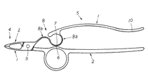
第一半体1と第二半体2とを交差枢着して、先端部に対象物3を挟持又は切断する開閉作業部4を設けると共に、基端部に前記開閉作業部4を開閉操作する開閉操作部5を設けた開閉作業具において、前記開閉操作部5に閉力を加えて前記開閉作業部4を閉動させ前記対象物3を挟持又は切断する際、前記対象物3を挟持した状態で前記開閉操作部5に加える前記閉力を増大させるに従い前記開閉操作部5が内方に撓むように構成して、前記開閉操作部5に前記閉力を増大させながら加えていっていることを、この開閉操作部5を握持する手若しくは押圧する手若しくは指先で感じる又は撓み量を目視することでわかるように構成し、この開閉操作部5の内方への撓みにより接近してゆき前記閉力が所定値になったとき受部6に当接する当接部7を開閉操作部5の撓み可動部8に設け、この受部6と当接部7とが当接した状態で前記閉力を更に増大させるとこの当接部7より基端側が更に撓む若しくは内方に可動するがこの増大した閉力は前記開閉作業部4には伝達されず前記対象物3を挟持する挟持力若しくは前記対象物3を切断する切断力は、前記受部6と前記当接部7とが当接した際に前記開閉操作部5に加えられていた前記閉力に応じた挟持力若しくは切断力以上とならないように構成したことを特徴とする開閉作業具に係るものである。
The
また、一対の第一半体1と第二半体2とを途中で重合交差させて枢着し、この対向する第一半体1と第二半体2との先端部を、挟持部若しくは切断部とする開閉作業部4とし、前記対向する第一半体1と第二半体2との基端部を、互いに内方の閉じ方向に押圧させる閉力を加えることで前記先端部の開閉作業部4が閉動して対象物3を挟持若しくは切断する開閉操作部5とし、前記開閉作業部4となる前記第一半体1の先端部と前記第二半体2の先端部とで前記対象物3を挟持した状態で、更に前記開閉操作部5に前記閉力を加えると、この閉力の増大に応じて少なくとも前記第一半体1の基端部若しくは前記第二半体2の基端部が内方へ撓むように構成し、この撓みによって可動する当接部7とこの当接部7が当接する受部6とを前記開閉操作部5に対向状態に設け、前記閉力を増大させてゆくことで前記当接部7を撓み可動させて前記受部6に接近させ、この閉力が所定値に達したとき前記当接部7が前記受部6に当接して、前記開閉操作部5に加える前記閉力を更に増大させ続けても、前記閉力の増大に応じて前記当接部7より基端側は更に撓む若しくは内方に可動するがこの増大する閉力は前記開閉作業部4に伝達されず前記対象物3を挟持する挟持力若しくは前記対象物3を切断する切断力は、前記受部6と前記当接部7が当接した際に前記開閉操作部5に加えられていた前記閉力に応じたピーク値となる挟持力若しくは切断力以上とならないように構成したことを特徴とする開閉作業具に係るものである。
Also, the pair of
また、前記開閉作業部4は、前記第一半体1の基端部と前記第二半体2の基端部とを対向状態に配設した前記開閉操作部5を、手で握持する若しくは指先で挟持し内方へ押圧する前記閉力を加えることで間隔が狭められる閉動動作をなして前記対象物3を挟持若しくは切断する前記第一半体1の先端部と前記第二半体2の先端部とから成り、この開閉作業部4の前記第一半体1の先端部と前記第二半体2の先端部とで前記対象物3を挟持した状態で若しくは切断途中でこの対象物3を挟持した状態で更に前記開閉操作部5に閉力を加えると、この開閉操作部5の少なくとも前記第一半体1若しくは前記第二半体2が内方へ撓むように構成し、この開閉操作部5の前記第一半体1若しくは前記第二半体2の一方の撓み可動部8に前記当接部7を設け、これと対向する他方に前記受部6を設け、前記開閉作業部4が閉動し前記対象物3を挟持するまでは前記当接部7と前記受部6とは当接せず、前記対象物3を挟持した際更に前記閉力を増大させることで前記撓み可動部8が撓み変形することにより前記当接部7が前記受部6に対して接近してゆき当接するように構成し、この当接部7は前記第一半体1と前記第二半体2とを交差枢着する枢着部9より基端側であって前記開閉操作部5を握持する若しくは指先で挟持して前記閉力を加える力点部10より先端側に設けたことを特徴とする請求項1,2のいずれか1項に記載の開閉作業具に係るものである。
Further, the opening /
また、前記第一半体1及び前記第二半体2の枢着部9よりも先端側を前記開閉作業部4とし、基端側を前記開閉操作部5とし、この開閉操作部5の握持部若しくは指先挟持部となる前記第一半体1の基端部と前記第二半体2の基端部の一方に内方に突出状態に前記当接部7を前記枢着部9寄りに設けると共に、他方にこの当接部7と当接する前記受部6を設けたことを特徴とする請求項1〜3のいずれか1項に記載の開閉作業具に係るものである。
Further, the opening /
また、前記開閉操作部5に加える閉力が前記開閉作業部4に伝達されこの閉力に応じて生じる前記対象物3を挟持する前記開閉作業部4の挟持力は、前記開閉操作部5の前記撓み可動部8が撓んでこの撓み可動部8に設けた前記当接部7が前記受部6に接近して当接するまでは前記開閉操作部5に加える閉力の増大に応じて増大し、前記当接部7と前記受部6とが当接した時点を境にして、更に前記開閉操作部5に加える閉力を増大させても、この開閉操作部5に加える閉力の増大に応じて増大せずに前記当接部7と前記受部6とが当接した当接時の前記閉力の所定値に応じた挟持力をピーク値として減少するように構成したことを特徴とする請求項2〜4のいずれか1項に記載の開閉作業具に係るものである。
Further, the closing force applied to the opening /
本発明は上述のように構成したから、挟持若しくは切断する対象物を開閉作業部で挟持し単に開閉操作部に閉力を増大させながら加えてゆくだけの極めて単純な操作で、対象物を開閉作業部で潰したり、破損させたり、或いは表面にキズを付けたりすること無しに挟持することができる画期的な開閉作業具となる。 Since the present invention is configured as described above, the object to be clamped or cut can be opened / closed by an extremely simple operation by simply holding the object to be opened / closed by the opening / closing operation unit and adding the closing force to the opening / closing operation unit. This is an epoch-making opening / closing work tool that can be pinched without being crushed or broken at the working portion or scratched on the surface.
具体的にいうと、本発明の開閉作業具で挟持操作によって潰したくないもの、壊したくないもの、或いは表面にキズを付けたくないものなどデリケートな構造の対象物を挟持する際、この対象物を開閉作業部で潰したり、破損させたり、或いはキズを付けたりしないように開閉操作部の閉じ操作を微妙な閉力で調整しながら慎重に操作することなく、単に対向する開閉操作部を互いに内方の閉じ方向に押圧させる閉力を増大させながら加える操作、例えば握持操作や指先での摘まみ操作といった極めて簡易な操作をするだけで上述したようなデリケートな構造の対象物を潰したり、破損させたり、或いは表面にキズを付けたりすることなく簡単に挟持することができる。 Specifically, when sandwiching an object having a delicate structure such as an object that does not want to be crushed by a clamping operation, an object that does not want to be damaged, or an object that does not want to scratch the surface, Without adjusting the opening / closing operation part with a delicate closing force so that the opening / closing operation part is not crushed, damaged or scratched, the opposing opening / closing operation parts are simply connected to each other. An operation to be applied while increasing the closing force to be pushed inward in the closing direction, such as a gripping operation or a pinching operation with a fingertip, can be used to crush an object with a delicate structure as described above. It can be easily sandwiched without breaking or scratching the surface.
即ち、本発明の開閉作業具は、いくら開閉操作部に閉力を加えていっても開閉作業部には開閉操作部に加えた所定値以上の閉力に応じた力が伝わらないので、開閉作業部はピーク値以上の挟持力で対象物を挟持することがなく、従って、例えば、微妙な閉力の力加減を調整することなくぎゅっと開閉操作部を握持したり指先で摘まんだりして閉じ方向に押圧させる閉力を加えて対象物を開閉作業部で挟持しても、このデリケートな構造の対象物を潰さず、破損させず、或いは表面にキズを付けずに挟持することができる。 That is, the opening / closing work tool of the present invention does not transmit a force corresponding to a closing force greater than a predetermined value applied to the opening / closing operation unit to the opening / closing operation unit, no matter how much the closing force is applied to the opening / closing operation unit. The working unit does not pinch the object with a pinching force higher than the peak value.For example, it does not adjust the delicate force of the closing force and grips the open / close operation part or picks it with the fingertip. Even if the object is clamped by the opening / closing operation part by applying a closing force that pushes it in the closing direction, the object with this delicate structure can be clamped without breaking or damaging the surface. it can.
例えば、血管などの潰れ易くキズ付き易い繊細なものを対象物として挟持する場合でも、予めこの対象物がどの程度の挟持力で潰れてしまうか、或いはどの程度の挟持力でキズが付いてしまうかを調べて、開閉作業部の挟持力のピーク値を、この事前に調べた対象物を潰したり表面にキズを付けたりする挟持力に達しず、それでいて十分に対象物を挟持することができる挟持力に設定することで、作業者は開閉操作部を握持操作若しくは指先で摘まみ操作してこの開閉操作部に加えていく閉力を開閉作業部に伝達し過ぎないように気にしながら少しずつ加えてゆくといった煩わしい操作をすることなく、何も気にせず、単に、開閉操作部を握持操作若しくは指先で摘まみ操作するだけで良いので、極めて容易に、且つ気楽に血管などの潰れ易くキズ付き易いデリケートな構造物を対象物として挟持することができる画期的な開閉作業具となる。 For example, even when a delicate object such as a blood vessel that is easily crushed or scratched is sandwiched as an object, the object is crushed in advance or with a certain degree of force. The peak value of the clamping force of the opening / closing work part does not reach the clamping force that crushes the object examined in advance or scratches the surface, and can still clamp the object sufficiently. By setting the pinching force, the operator can take care not to transmit the closing force applied to the opening / closing operation unit to the opening / closing operation unit by gripping the opening / closing operation unit or picking it with a fingertip. You don't have to bother to add it little by little, you don't have to worry about anything, you just need to hold or open the open / close operation part with your fingertips. Easy to crush An innovative closing the implement which can be clamped as an object to scratch easily delicate structures.
しかも、開閉操作部の撓みは、対象物を挟持したり切断したりする際の抵抗によって生じる弾性力の反作用であるので、撓みによる弾性力の反作用を開閉操作部を操作する手や指先で感じ取ることで作業者は開閉作業部が対象物を掴んだということを確認でき、また、この開閉操作部が撓み続けることで、この撓みの弾性力の反作用も作業者の手や指先に伝わり続けるので、作業者は常に開閉作業部が対象物を掴み続けていることを感じ取ることができることとなり、よって、開閉作業部が対象物をきちんと挟持しているかどうかの不安感を抱くことなく対象物を挟持していることを確信し安心して挟持作業することができる実用性に優れた画期的な開閉作業具となる。 Moreover, since the bending of the opening / closing operation unit is a reaction of elastic force caused by resistance when the object is pinched or cut, the reaction of the elastic force due to bending is sensed by a hand or fingertip that operates the opening / closing operation unit. Thus, the operator can confirm that the opening / closing operation part has grasped the object, and the opening / closing operation part continues to bend, so that the reaction of the elastic force of the bending continues to be transmitted to the operator's hands and fingertips. Therefore, the operator can always feel that the opening / closing operation unit keeps grasping the object, so that the object can be held without feeling uneasy about whether the opening / closing operation unit is holding the object properly. This is an epoch-making opening and closing work tool with excellent practicality that can be held securely with confidence.
好適と考える本発明の実施形態を、図面に基づいて本発明の作用を示して簡単に説明する。 An embodiment of the present invention which is considered to be suitable will be briefly described with reference to the drawings showing the operation of the present invention.
本発明の開閉作業具を用いて対象物3を挟持したり切断したりする際は、対向する第一半体1と第二半体2との先端部、即ち挟持部若しくは切断部となる開閉作業部4の間に対象物3を配置し、対向する第一半体1と第二半体2との基端部、即ち開閉操作部5にこの開閉操作部5を、例えば握持操作若しくは指先で摘まみ操作して互いに内方の閉じ方向に押圧させる閉力を加えることで開閉作業部4が閉動して対象物3を挟持する。
When the
この対象物3を開閉作業部4で挟持した状態で更に開閉操作部5に閉力を増大させながら加えてゆくことで、対象物3に対して挟持力若しくは切断力が作用すると同時に、この対象物3を挟持若しくは切断する際の抵抗力が生じ、この抵抗力によって開閉操作部5が内方へ撓み始める。
When the
この開閉操作部5が内方に撓むことで、この開閉操作部5の撓み可動部8に設けた当接部7がこの当接部7と対向状態に設けた受部6に接近する。
When the opening /
このように、開閉操作部5を、例えば握持したり指先で摘まんだりして、この開閉操作部5に閉力を加えた際に生じる開閉操作部5の撓みは、開閉作業部4で対象物3を挟持したり切断したりする際の抵抗によって生じる弾性力の反作用であるので、この撓みによる弾性力の反作用を、開閉操作部5を操作する手や指先で感じ取ることで作業者は開閉作業部4が対象物3を掴んだということを容易に把握することができる。
In this manner, the opening /
このように作業者は開閉操作部5が撓むことによって対象物3を掴んでいることを手や指先で感じ取り安心して挟持操作を続けることができ、更に開閉操作部5に閉力を増大させながら加えてゆくと、開閉操作部5は更に内方に撓んでゆき、この開閉操作部5の撓みに伴って当接部7と受部6とが更に接近してゆき、開閉操作部5に加えられる閉力が所定値に達したときに当接部7が受部6に当接する。
In this way, the operator can feel that he / she is grasping the
この当接部7と受部6とが当接することで、開閉操作部5に更に閉力を増大させながら加え続けても、この閉力の増大に応じて当接部7より第一半体1と第二半体2の基端側、即ち開閉操作部5は更に内方に撓んでゆくが、当接部7より第一半体1と第二半体2の先端側、即ち開閉作業部4にはこの増大する閉力は伝達されなくなる。
Even if the
即ち、開閉操作部5が撓むことによって、第一半体1と第二半体2とに設けた当接部7と受部6とが当接し、この当接部7と受部6との当接が開閉作業部4への閉力の伝達を抑制するので、作業者はこの当接部7と受部6とが当接することで、開閉作業部4の挟持力がこれ以上開閉操作部5に閉力を加えても増大しないピーク値となったことを把握することができる。
That is, when the opening /
また、この当接部7と受部6とが当接し、開閉操作部5に閉力を増大させながら加えていっても、この増大する閉力が開閉作業部4に伝達されない状態となった際には、この開閉作業部4の挟持力は、例えば、当接部7と受部6とが当接した時点の挟持力のまま、即ち、一定の挟持力を保った状態となる、若しくはこの当接部7と受部6とが当接した当接時の挟持力がピーク値となる最大挟持力となり、この当接部7と受部6とが当接した当接時を境に更に開閉操作部5に閉力を増大させながら加えることによって開閉作業部4の挟持力が減少してゆく状態となる。
Further, the
また、当接部7と受部6とが当接した後も開閉操作部5に閉力を増大させながら加えることで、開閉操作部5はより一層撓んで、作業者が握持し易い状態、若しくは指先で摘まみ易い状態を保持することができ、このような握持し易い状態、若しくは指先で摘まみ易い状態まで開閉操作部5に閉力を加えても、開閉作業部4で挟持している対象物3には、ピーク値以上の挟持力が掛からないので、作業者は開閉操作部5から開閉作業部4に伝達される閉力を気にすることなくこの開閉操作部5の閉じ操作、即ち、対向する第一半体1と第二半体2との開閉操作部5を互いに内方の閉じ方向に押圧させる閉力を微妙に調整することなく加えることができることとなる。
Further, even after the
即ち、対象物3には開閉操作部5に所定の閉力が加えられ、当接部7と受部6とが当接した時点のピーク値となる挟持力以上の力が作用しないので、この当接部7と受部6とが当接した時点のピーク値となる挟持力が対象物3を潰したり、破損させたり、或いは表面にキズを付けたりする必要以上の挟持力よりも小さい挟持力となり、且つ十分に対象物3を挟持する力を有する挟持力となるように挟持力のピーク値を設定することで、作業者は従来のように対象物3を潰さないように、破損させないように、或いは、表面にキズを付けないように、開閉操作部5に加える閉力の力加減を微妙に調整しながら慎重にゆっくりと作業しなくてもよく、或いは、閉力を加え過ぎないように、例えば手の握持動作や指先の摘まみ動作を中途半端状態で止めて手や指に負担を掛けてしまうといったこともなく、例えば単に手で開閉操作部5を握持する、若しくは単に指先で開閉操作部5を摘まんでゆき、この開閉操作部5に閉力を増大させながら加えてゆくだけの極めて簡単な操作で、挟持操作によって潰したくないもの、壊したくないもの、或いは表面にキズを付けたくないものなどデリケートな構造の対象物3を容易に挟持することができ、しかも、従来に比してスピーディーに操作できるので作業効率も格段に向上する極めて実用性、作業性に優れた画期的な開閉作業具となる。
That is, a predetermined closing force is applied to the
また更に、当接部7が受部6に当接して開閉作業部4に閉力が伝達されない状態になった後も、作業者は開閉操作部5を更に握持する若しくは指先で摘まむことで、この開閉操作部5を撓ませて、この撓みによって生じる弾性力の反作用を、この開閉操作部5を握っている手若しくは摘まんでいる指で感じ取ることで、作業者は開閉操作部5に閉力をどの程度加えているかもおおよそ把握することができ、更には、開閉作業部4で対象物3を掴み続けていることを確信し安心して作業することができ、更に、例えば、装置やロボットなどを用いて人の手以外でこの開閉操作部5に閉力を加える場合でも、開閉操作部5の撓み量を目視することで、作業者が手や指で閉力の増大を感じ取るのと同様にこの開閉操作部5に閉力を増大させながら加えていることが容易に把握できるとともに、開閉作業部4が対象物3を掴み続けていることが把握できる。
Furthermore, even after the
従って、本発明を、例えば、手術の際に血管を挟持する手術用器具として用いた場合でも、予め血管を潰してしまう或いはキズをつけてしまう挟持力を把握しておき、開閉作業部4に伝達される挟持力の最大値(ピーク値)がこの予め把握しておいた血管を潰してしまう或いはキズを付けてしまう挟持力よりも小さい値となるよう所定の閉力の値で当接部7と受部6とが当接するように設定することで、開閉作業部4にはピーク値以上の挟持力が作用しないので、作業者は血管を挟持する際にこの血管を潰してしまうというプレッシャーから開放され、しかも、血管のような潰したくないもの、キズを付けたくないものを対象物3として挟持する際にも、この対象物3を掴んでいることが開閉操作部5の撓み加減を手や指先で感じ取ることで容易に把握することができ、十分な挟持力で対象物3を挟持しているかどうか分からない不安感を抱くこともなく、気楽に、そして容易に血管を挟持することができる実用性に優れた画期的な開閉作業具となる。
Therefore, even when the present invention is used, for example, as a surgical instrument for clamping a blood vessel during surgery, the grasping force that crushes or scratches the blood vessel in advance is grasped, and The abutting portion with a predetermined closing force value so that the maximum value (peak value) of the clamping force transmitted is smaller than the clamping force that crushes or scratches the previously grasped blood vessel. 7 and the receiving
本発明の具体的な実施例について図面に基づいて説明する。 Specific embodiments of the present invention will be described with reference to the drawings.
本実施例は、一対の第一半体1と第二半体2とを途中で重合交差させて枢着し、この対向する第一半体1と第二半体2との先端部を、挟持部若しくは切断部とする開閉作業部4とし、前記対向する第一半体1と前記第二半体2の基端部を、互いに内方の閉じ方向に押圧させる閉力を加えることで前記先端部の開閉作業部4が閉動して対象物3を挟持若しくは切断する開閉操作部5とし、この開閉作業部4の前記第一半体1の先端部と前記第二半体2の先端部とで前記対象物3を挟持した状態で、更に前記開閉操作部5に前記閉力を加えると、この閉力の増大に応じて少なくとも前記第一半体1の基端部若しくは前記第二半体2の基端部が内方へ撓むように構成し、この撓みによって可動する当接部7とこの当接部7が当接する受部6とを対向状態にして前記開閉操作部5に設け、前記閉力を増大させてゆくことで前記当接部7を撓み可動させて前記受部6に接近させ、この閉力が所定値に達したとき前記当接部7が前記受部6に当接して、前記開閉操作部5に加える前記閉力を更に増大させ続けても、前記閉力の増大に応じて前記当接部7より基端側は更に撓むがこの増大する前記閉力は前記開閉作業部4に伝達されず前記対象物3には前記当接部7と前記受部6とが当接した当接時の前記所定値以上の閉力に応じたピーク値となる挟持力若しくは切断力以上の挟持力が伝達されないように構成した開閉作業具である。
In the present embodiment, the pair of
具体的には、第一半体1及び第二半体2は、適宜な材質、例えば、金属または合成樹脂からなる部材を所定形状に形成し、夫々に、先端側に対象物3を挟持する挟持部としての開閉作業部4を設け、基端側にこの開閉作業部4を開閉操作する開閉操作部5を設け、この開閉作業部4と開閉操作部5との境界となる位置に枢着部9を設けた構成とし、本実施例では、この開閉作業部4と開閉操作部5とを一体形成した構成としている。尚、本実施例では上述したように第一半体1及び第二半体2は夫々一体成形した構成としているが、開閉作業部4と開閉操作部5とを分割自在な構成としても良い。
Specifically, the
具体的には、開閉作業部4は、第一半体1の基端部と第二半体2の基端部とを対向状態に配設した開閉操作部5を、手で握持する若しくは指先で挟持し内方へ押圧する閉力を加えることで間隔が狭められる閉動動作をなして対象物3を挟持する第一半体1の先端部と第二半体2の先端部とで構成している。尚、本実施例では、この開閉作業部4を対象物3を挟持する挟持部に形成した構成としているが、この先端部に切断刃を設けて対象物3を切断する切断部とする構成としても良く、本実施例の特性を発揮するものであれば適宜採用し得るものである。
Specifically, the opening /
また、この開閉作業部4を開閉操作する開閉操作部5は、全体的な形状を外方に凸となる湾曲形状に形成し、基端部に指を挿入し摘まみ操作する指挿入部11を設け、先端部に撓み可動部8を設けた構成としており、この指挿入部11に指を挿入し閉力を加える点を力点部10とし、この力点部10に指先を摘まみ操作することで生じる閉力を加えることで開閉作業部4が閉動し対象物3を挟持し、この開閉作業部4が対象物3を挟持した挟持力の反作用によって撓み可動部8が撓み変形して開閉操作部5が撓む若しくは可動する構成としている。
The opening /
具体的には、指挿入部11は指先を挿入し得る直径を有する円形状に形成しており、このように円形状に形成した指挿入部11に指先を挿入して開閉操作部5を操作することで、内方に閉力を加える閉じ操作だけでなく、この開閉操作部5を外方に広げる操作も指二本で操作できるように構成している。
Specifically, the finger insertion part 11 is formed in a circular shape having a diameter into which the fingertip can be inserted, and the finger insertion part 11 is inserted into the circular finger insertion part 11 in this way to operate the opening /
尚、この指挿入部11の形状は、本実施例に示す円形状に限定することなく、図14に示すように、内方に湾曲した形状や直線的な形状でも良く、本実施例の特性を発揮するもの、或いは、近似する特性を発揮するものであれば適宜採用し得るものである。 The shape of the finger insertion portion 11 is not limited to the circular shape shown in this embodiment, but may be an inwardly curved shape or a linear shape as shown in FIG. Any material can be used as long as it exhibits the above or a property that approximates.
また、本実施例では、指挿入部11を設けて指先で摘まみ操作する構成としているが、指挿入部11を設けず、開閉操作部5を握持操作するように構成しても良く、或いは、人の手や指先で操作するのではなく、機械、装置、ロボットなどで操作するよう構成しても良く、その形状、構成は適宜変更可能なものとする。
In this embodiment, the finger insertion unit 11 is provided and the fingertip is picked up. However, the finger insertion unit 11 may not be provided, and the opening /
また、撓み可動部8は、具体的には、アルミ板材若しくはSUS板材を湾曲させ略S字形状に形成し、第一半体1と第二半体2とを重合枢着した際に、これら第一半体1の撓み可動部8と第二半体2の撓み可動部8とが対向状態且つ左右対称状態となるように第一半体1と第二半体2とに夫々設けた構成としている。
In addition, the bending
更に具体的に説明すると、この撓み可動部8は、内方に向かって凸となる基端側湾曲部8aと外方に向かって凸となる先端側湾曲部8bとからなり、基端側湾曲部8aの一端を開閉操作部5の先端部より稍基端側の位置から内方に突設し、他端側を第一半体1若しくは第二半体2の先端側、即ち、開閉作業部4側に向けて円を描くように湾曲し基端側湾曲部8aを形成し、この基端側湾曲部8aの他端を外方に凸となるように湾曲して先端側湾曲部8bを形成し、この先端側湾曲部8bの一端を枢着部9と連設した構成としている。
More specifically, the bending
また、この撓み可動部8は、図7(a)に示すように厚みを薄くした構成、或いは図7(b)に示すように厚みを厚くした構成としても良く、このように撓み可動部8の厚みを変えることで、この撓み可動部8の撓み変形する度合いを変化させることができる。
In addition, the bending
尚、本実施例では、この撓み可動部8を第一半体1と第二半体2との両方に設けた構成としているが、図13,図14に示すように、この撓み可動部8を第一半体1若しくは第二半体2のいずれか一方のみに設けた構成としても良く、また、この撓み可動部8は、上述した材質・形状に限定するものではなく、例えば、棒材でも良く、また、所望の撓みが生じるように適宜厚みや直径を設定したり、孔を形成して撓みを調整したり、或いは、材質を変更(例えば合成樹脂など)するなどしても良く、本実施例の特性を発揮するものであれば適宜採用し得るものである。
In the present embodiment, the bending
また、この対向する撓み可動部8の一方の基端側湾曲部8aに当接部7を設け、他方の基端側湾曲部8aに受部6を設けた構成としている。
In addition, the abutting
具体的には、本実施例では、この当接部7と受部6とは、開閉操作部5に閉力増大させながら加えてゆき、これによって対向状態に設けた撓み可動部8が内方に撓み変形し接近してゆき、開閉操作部5に加えられる閉力が所定値になった際に当接する接点の一方を当接部7、他方を受部6としており、本実施例では、第一半体1側の接点を当接部7とし、第二半体2側の接点を受部6とし、これらは夫々の基端側湾曲部8aの最も内方に突出した位置(点)付近となるように構成している。
Specifically, in the present embodiment, the
また、この当接部7と受部6とは、開閉作業部4に対象物3を挟持していない状態で単に閉じ状態にしただけでは当接しない構成としている。言い換えると、この開閉作業部4が完全に閉動した状態、即ち、第一半体1の先端部と第二半体2の先端部とが接した状態において、当接部7と受部6との間に所定の間隔を設けた構成とし、この当接部7と受部6とは、撓み可動部8が撓むことによって当接するように構成している。
In addition, the
また、この当接部7と受部6との間隔は、図8(a)に示すように間隔を狭くした構成、或いは図8(b)に示すように間隔を広くした構成としても良く、このように当接部7と受部6との間隔を変えることで、この撓み可動部8が撓み変形し始めてから当接部7と受部6とが当接するまでに開閉操作部5に加える閉力が変わるので、開閉作業部4に伝達される挟持力を変えることができる。
In addition, the interval between the
即ち、対象物3を挟持する挟持力を小さくしたい場合は、当接部7と受部6との間隔を狭く設定し早く当接部7と受部6とを当接させて開閉作業部4に開閉操作部5の閉力が伝達されないように構成し、逆に大きな挟持力で挟持させたい場合は、当接部7と受部6との間隔を広くした構成とすると良く、挟持する対象物3に適切に対応した挟持力となるよう当接部7と受部6との間隔は適宜設定変更可能なものとする。
That is, when it is desired to reduce the clamping force for clamping the
上述のように構成した本実施例の作用・効果について以下に説明する。 The operation and effect of the present embodiment configured as described above will be described below.
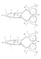
図3〜図6は、本実施例の使用状態、即ち、開閉作業部4で対象物3を挟持し、開閉操作部5に閉力を加えていった際の本実施例の状態を示す図である。
3 to 6 are diagrams showing the use state of the present embodiment, that is, the state of the present embodiment when the
具体的には、図3は、開閉作業部4で対象物3を挟持した状態を示す図である。この開閉作業部4で対象物3を挟持している状態で指挿入部11の力点部10に閉力を増大させながら加えてゆくと、図4に示すように、撓み可動部8が内方に撓み変形し、開閉操作部5が内方に撓むと共に撓み可動部8の基端側湾曲部8aに設けた当接部7と受部6とが接近し始める。
Specifically, FIG. 3 is a diagram illustrating a state in which the
更に力点部10に閉力を増大させながら加えてゆくと、更に撓み可動部8が内方に撓み変形し当接部7と受部6とが更に接近すると共に、開閉操作部5が更に内方に撓んでゆき、この閉力が所定値に達すると、図5に示すように、当接部7と受部6とが当接する。
If the closing force is further applied to the
この図3〜図5の状態では、開閉操作部5(指挿入部11の力点部10)に加えた閉力が開閉作業部4に伝達され、開閉作業部4にはてこの原理で開閉操作部5に加えた閉力に応じた挟持力が生じ、この加えた閉力に応じた挟持力で対象物3を挟持することとなる。
3 to 5, the closing force applied to the opening / closing operation unit 5 (
この当接部7と受部6とが当接した状態となっても、更に開閉操作部5に閉力を増大させながら加えてゆくと、図6に示すように、更に撓み可動部8が内方に撓み変形し、開閉操作部5が更に内方に撓んでゆくが、この当接部7と受部6とが当接することで、この当接部7と受部6との接点より先端側は、閉動動作しようとする動作が伝わらず、従って、開閉作業部4には開閉操作部5に更に増大しながら加えた閉力に応じた挟持力は生じず、開閉作業部4の挟持力は当接部7と受部6とが当接した時点の挟持力のまま、若しくは、減少する。
Even when the
本実施例では、撓み可動部8を内方に凸となる基端側湾曲部8aと外方に凸となる先端側湾曲部8bとを連結した略S字形状に形成した構成としており、開閉操作部5に閉力を増大させながら加えてゆき、開閉操作部5に加えられる閉力が所定値となり当接部7と受部6とが当接するまでは、基端側湾曲部8aと先端側湾曲部8bとのいずれも内方に撓み変形するが、当接部7と受部6とが当接した後で更に開閉操作部5に所定値以上の閉力が加えられると、基端側湾曲部8aの当接部7(受部6)よりも基端側は更に内方に撓み変形するが、この基端側湾曲部8aの基端側の撓み変形により、この基端側湾曲部8aの当接部7(受部6)よりも先端側を外方に押圧する力が作用する。
In this embodiment, the flexible
この基端側湾曲部8aの先端側が外方に押圧されることで先端側湾曲部8bが外方の開き方向に押圧される力が作用し、よって、開閉作業部4が開き方向に動作し対象物3を挟持する挟持力が減少するように構成している。
When the distal end side of the proximal end
即ち、本実施例は、図9〜図11の開閉操作部に加える閉力と、この閉力を加えた際の開閉操作部の撓み移動量と、開閉作業部に伝達される挟持力との関係に示すように、開閉作業部4に対象物3を挟持した状態で開閉操作部5に閉力を増大させながら加えてゆくと、始めは撓み可動部8が撓み変形することで開閉操作部5は内方に撓み移動してゆき、開閉作業部4には増大してゆく閉力に応じて挟持力が増大してゆく。
That is, in this embodiment, the closing force applied to the opening / closing operation unit shown in FIGS. 9 to 11, the bending movement amount of the opening / closing operation unit when this closing force is applied, and the clamping force transmitted to the opening / closing operation unit. As shown in the relationship, when the closing force is applied to the opening /
そして、開閉操作部5に加えられる閉力が所定値となった際に当接部7と受部6とが当接することで開閉作業部4にはこれ以上増大する閉力に応じた挟持力が伝達されなくなるので、この当接部7と受部6とが当接する当接時の挟持力が最大挟持力、即ち、開閉作業部4の挟持力のピーク値となり、これを境にして、開閉操作部5に閉力増大させながら加え続けることで、逆に開閉作業部4を開き方向に動作させるので開閉作業部4の挟持力は減少傾向を示すこととなる。
When the closing force applied to the opening /
図9〜図11について、具体的に説明すると、図9は、本実施例の基本構成、即ち、撓み可動部8の厚みが薄く、当接部7と受部6との間隔が狭く設定したものであり、図10は、この基本構成において、当接部7と受部6との間隔はそのままにし、撓み可動部8の厚みを厚く(2倍の厚み)設定した場合のものを示す。
9 to 11 will be described in detail. In FIG. 9, the basic configuration of the present embodiment, that is, the thickness of the bending
また、図11は、上述した基本構成において、当接部7と受部6との間隔を広く(2倍の間隔)設定した場合のものを示す。
Further, FIG. 11 shows a case where the interval between the
本実施例は、てこの原理によって、開閉操作部5に加えられた閉力が開閉作業部4に伝達される際に、加えられた閉力の5倍の挟持力となるように設計している。
This embodiment is designed so that when the closing force applied to the opening /
この開閉操作部5に加えられる閉力が所定値に達するまでは、この開閉操作部5に閉力を増大させながら加えてゆくと開閉操作部5の撓み移動量は一定に増加してゆき、開閉作業部4が対象物3を挟持する挟持力は閉力の5倍の傾きで増大してゆく。
Until the closing force applied to the opening /
そして、開閉操作部5に加えられる閉力が所定値に達したところで、当接部7と受部6とが当接することで、開閉作業部4の挟持力はピーク値となり、これ以降、開閉操作部5に閉力を増大させていっても、挟持力は減少してゆく。
When the closing force applied to the opening /
また、この当接部7と受部6との当接を境に、開閉操作部5に加えられる閉力によって開閉操作部5が撓み移動する量が変化する。具体的には、開閉操作部5は撓み難くなるので、開閉操作部5の撓み移動量を一定状態で増大させるには、開閉操作部5に加える閉力をより大きな閉力にしなければならないこととなる。
In addition, the amount by which the opening /
また、例えば、この開閉操作部5に閉力を増大させながら加え続けてゆくことで、いずれ開閉作業部4が対象物3を挟持する挟持力がゼロになり、開閉作業部4は対象物3を挟持できなくなり、開閉作業部4から対象物3を開放する状態が発生する。
Further, for example, by continuing to apply the closing operation force to the opening /
即ち、一般的な開閉作業具は、対象物3を開閉作業部4で挟持する場合は、開閉作業部4を閉動させるために開閉操作部5に閉じ方向の力を加え、対象物3を開閉作業部4から開放する場合は、開閉操作部5に開き方向の力を加える二種類の操作を行うが、本実施例は対象物3を挟持する場合も、開放する場合も開閉操作部5に閉じ方向の力を加える一操作のみ、即ち、ワンアクションで操作することもできる。
That is, when a general opening / closing work tool holds the
従って、本実施例の開閉作業具で挟持操作によって潰したくないもの、壊したくないもの、或いは表面にキズを付けたくないものなどデリケートな構造の対象物3を挟持する際、開閉作業部4に対象物3を潰さない、壊さない、或いは表面にキズを付けない挟持力で且つ十分に対象物3を挟持することが可能な挟持力が生じる所定の閉力を加えた際に当接部7と受部6とが当接するように構成することで、この対象物3を開閉作業部4で潰したり、破損させたり、或いはキズを付けたりしないように開閉操作部5の閉じ操作を微妙な閉力で調整しながら慎重に操作することなく、単に対向する開閉操作部5を互いに内方の閉じ方向に押圧させる閉力を増大させながら加える操作、例えば握持操作や指先での摘まみ操作といった極めて簡易な操作をするだけで上述したようなデリケートな構造の対象物3を潰したり、破損させたり、或いは表面にキズを付けたりすることなく簡単に挟持することができるので余計な気を使う必要がなくなり作業がし易くなり、更に、従来に比してスピーディーに操作できるので作業効率も格段に向上する実用性、作業性に優れた画期的な開閉作業具となる。
Therefore, when the
尚、本発明は、本実施例に限られるものではなく、各構成要件の具体的構成は適宜設計し得るものである。 Note that the present invention is not limited to this embodiment, and the specific configuration of each component can be designed as appropriate.
1 第一半体
2 第二半体
3 対象物
4 開閉作業部
5 開閉操作部
6 受部
7 当接部
8 撓み可動部
9 枢着部
10 力点部
DESCRIPTION OF
10 Power point
Claims (5)
A closing force applied to the opening / closing operation portion is transmitted to the opening / closing operation portion, and the holding force of the opening / closing operation portion that holds the object generated in response to the closing force is that the bending movable portion of the opening / closing operation portion is bent. Until the abutting portion provided on the bending movable portion approaches and abuts on the receiving portion, it increases as the closing force applied to the opening / closing operation portion increases, and the abutting portion and the receiving portion are in contact with each other. Even if the closing force applied to the opening / closing operation part is further increased from the point of contact, the contact part and the receiving part do not increase in accordance with the increase in the closing force applied to the opening / closing operation part. open closed working tool according to any one of claims 2-4, characterized in that the clamping force corresponding to a predetermined value of the closing force at the time of contact in abutment configured to reduce a peak value .
Priority Applications (4)
| Application Number | Priority Date | Filing Date | Title |
|---|---|---|---|
| JP2010234143A JP4995961B2 (en) | 2010-10-19 | 2010-10-19 | Opening / closing tool |
| US13/395,774 US8863623B2 (en) | 2010-10-19 | 2010-12-10 | Open-close work implement |
| CN201080040939.0A CN102574278B (en) | 2010-10-19 | 2010-12-10 | Open-close work implement |
| PCT/JP2010/072277 WO2012053123A1 (en) | 2010-10-19 | 2010-12-10 | Open-close work implement |
Applications Claiming Priority (1)
| Application Number | Priority Date | Filing Date | Title |
|---|---|---|---|
| JP2010234143A JP4995961B2 (en) | 2010-10-19 | 2010-10-19 | Opening / closing tool |
Publications (3)
| Publication Number | Publication Date |
|---|---|
| JP2012086292A JP2012086292A (en) | 2012-05-10 |
| JP2012086292A5 JP2012086292A5 (en) | 2012-06-28 |
| JP4995961B2 true JP4995961B2 (en) | 2012-08-08 |
Family
ID=45974855
Family Applications (1)
| Application Number | Title | Priority Date | Filing Date |
|---|---|---|---|
| JP2010234143A Expired - Fee Related JP4995961B2 (en) | 2010-10-19 | 2010-10-19 | Opening / closing tool |
Country Status (4)
| Country | Link |
|---|---|
| US (1) | US8863623B2 (en) |
| JP (1) | JP4995961B2 (en) |
| CN (1) | CN102574278B (en) |
| WO (1) | WO2012053123A1 (en) |
Cited By (1)
| Publication number | Priority date | Publication date | Assignee | Title |
|---|---|---|---|---|
| WO2014203578A1 (en) | 2013-06-21 | 2014-12-24 | ナシモト工業株式会社 | Work device |
Families Citing this family (4)
| Publication number | Priority date | Publication date | Assignee | Title |
|---|---|---|---|---|
| JP2014117780A (en) * | 2012-12-18 | 2014-06-30 | Nashimoto Kogyo Kk | Open-close work implement |
| KR101489120B1 (en) * | 2014-05-02 | 2015-02-04 | 손원호 | Vise grip plier |
| EP3691831A2 (en) * | 2017-07-10 | 2020-08-12 | Nigel Buchanan | Pliers |
| WO2022256056A1 (en) * | 2021-06-04 | 2022-12-08 | Groh Daniel | Systems and methods associated with pliers |
Family Cites Families (21)
| Publication number | Priority date | Publication date | Assignee | Title |
|---|---|---|---|---|
| US2736218A (en) * | 1956-02-28 | atkeson | ||
| US3282137A (en) * | 1964-12-30 | 1966-11-01 | Bendix Corp | Actuating mechanism for plier type devices |
| US3653389A (en) * | 1970-01-19 | 1972-04-04 | Amp Inc | Disposable forceps |
| US3675359A (en) * | 1970-11-12 | 1972-07-11 | Sargent & Co | Fish mouth implements |
| GB1427397A (en) * | 1973-04-24 | 1976-03-10 | Ici Ltd | Forceps |
| GB1509645A (en) * | 1975-10-20 | 1978-05-04 | Fletcher Terry Co | Glass breaking pliers |
| US4563833A (en) * | 1983-06-13 | 1986-01-14 | Aucoin Raymond U | Fish holding device |
| JPS6289948U (en) * | 1985-11-27 | 1987-06-09 | ||
| US5451231A (en) * | 1994-03-11 | 1995-09-19 | Ryder International Corporation | Surgical staple remover |
| US5522290A (en) * | 1994-04-18 | 1996-06-04 | Visser; Steven C. | Compliant pliers |
| US5893307A (en) * | 1997-04-25 | 1999-04-13 | Tao; Liang-Che | Pliers with biasing element |
| FR2775504B1 (en) * | 1998-02-27 | 2000-05-19 | Bost Garnache Ind | DAMPING AND / OR OPENING SPRING FOR A TOOL, AND CORRESPONDING TOOL |
| US6050279A (en) * | 1998-06-08 | 2000-04-18 | Advanced Micro Devices, Inc. | Apparatus and method for immersing an object in a liquid such that a lower surface of the object does not touch a bottom surface of a container holding the liquid |
| DE29822558U1 (en) * | 1998-12-18 | 1999-02-18 | Aesculap AG & Co. KG, 78532 Tuttlingen | Vascular clip |
| CN2407886Y (en) * | 2000-02-21 | 2000-11-29 | 曾绍谦 | Power saving convenient clipper |
| CN200973731Y (en) * | 2007-05-29 | 2007-11-14 | 许林 | Vascular blocking clamp without generating wound |
| KR101140182B1 (en) * | 2008-10-07 | 2012-05-02 | 미쓰보시 다이야몬도 고교 가부시키가이샤 | Plier for fragile material |
| CN201290718Y (en) * | 2008-11-17 | 2009-08-19 | 王爱芹 | Handle combination type vascular clamp |
| CN201510373U (en) * | 2009-09-08 | 2010-06-23 | 广州医学院第一附属医院 | Porous elastic vessel clip |
| CN201524962U (en) * | 2009-09-23 | 2010-07-14 | 布和 | Soft plier |
| US20120132040A1 (en) * | 2010-11-30 | 2012-05-31 | Jeffrey Mastroianni | Pivoting-lever hand tool with resilient closed-loop handle |
-
2010
- 2010-10-19 JP JP2010234143A patent/JP4995961B2/en not_active Expired - Fee Related
- 2010-12-10 US US13/395,774 patent/US8863623B2/en not_active Expired - Fee Related
- 2010-12-10 CN CN201080040939.0A patent/CN102574278B/en not_active Expired - Fee Related
- 2010-12-10 WO PCT/JP2010/072277 patent/WO2012053123A1/en active Application Filing
Cited By (1)
| Publication number | Priority date | Publication date | Assignee | Title |
|---|---|---|---|---|
| WO2014203578A1 (en) | 2013-06-21 | 2014-12-24 | ナシモト工業株式会社 | Work device |
Also Published As
| Publication number | Publication date |
|---|---|
| CN102574278A (en) | 2012-07-11 |
| WO2012053123A1 (en) | 2012-04-26 |
| JP2012086292A (en) | 2012-05-10 |
| US20120291293A1 (en) | 2012-11-22 |
| CN102574278B (en) | 2014-12-10 |
| US8863623B2 (en) | 2014-10-21 |
Similar Documents
| Publication | Publication Date | Title |
|---|---|---|
| JP4995961B2 (en) | Opening / closing tool | |
| US5562699A (en) | Forceps | |
| US20020077649A1 (en) | Manually adjustable scissors or forceps | |
| US4524648A (en) | Fixation tweezers | |
| WO1995009566A1 (en) | Hingeless tool useful in surgery | |
| JP5364014B2 (en) | One-hand-grip manual work tool | |
| US20240090910A1 (en) | Surgical instrument having a thenar eminence handle and method for use thereof | |
| US20210196300A1 (en) | Surgical instruments with coupling members to effect multiple pivot axes | |
| US3399456A (en) | Finger-held tools | |
| US11737746B2 (en) | Forceps with integrated blade | |
| WO2014097494A1 (en) | Opening/closing tool | |
| US20070016248A1 (en) | Medical gripping and/or cutting instrument | |
| US5572914A (en) | Tweezer-pliers having multiple gripping means | |
| JP5526167B2 (en) | Opening / closing tool | |
| US20200229836A1 (en) | Medical instrument | |
| JP7122952B2 (en) | Forceps and Disposable Medical Supplies Set | |
| US3553819A (en) | Method of using finger-held tools | |
| JP5498519B2 (en) | Opening / closing tool | |
| JP5438157B2 (en) | Opening / closing tool | |
| EP3202349A1 (en) | Treatment apparatus | |
| JP3118904U (en) | Medical cutter | |
| CN210843322U (en) | Arc double eyelid forceps | |
| JP2020110593A (en) | Tweezers | |
| KR20220161835A (en) | Pincette that can control elasticity | |
| AU2013203870B2 (en) | Hand held instrument |
Legal Events
| Date | Code | Title | Description |
|---|---|---|---|
| A521 | Written amendment |
Free format text: JAPANESE INTERMEDIATE CODE: A523 Effective date: 20120229 |
|
| A621 | Written request for application examination |
Free format text: JAPANESE INTERMEDIATE CODE: A621 Effective date: 20120229 |
|
| A521 | Written amendment |
Free format text: JAPANESE INTERMEDIATE CODE: A523 Effective date: 20120302 |
|
| A871 | Explanation of circumstances concerning accelerated examination |
Free format text: JAPANESE INTERMEDIATE CODE: A871 Effective date: 20120229 |
|
| TRDD | Decision of grant or rejection written | ||
| A01 | Written decision to grant a patent or to grant a registration (utility model) |
Free format text: JAPANESE INTERMEDIATE CODE: A01 Effective date: 20120412 |
|
| A975 | Report on accelerated examination |
Free format text: JAPANESE INTERMEDIATE CODE: A971005 Effective date: 20120405 |
|
| A01 | Written decision to grant a patent or to grant a registration (utility model) |
Free format text: JAPANESE INTERMEDIATE CODE: A01 |
|
| A61 | First payment of annual fees (during grant procedure) |
Free format text: JAPANESE INTERMEDIATE CODE: A61 Effective date: 20120510 |
|
| FPAY | Renewal fee payment (event date is renewal date of database) |
Free format text: PAYMENT UNTIL: 20150518 Year of fee payment: 3 |
|
| R150 | Certificate of patent or registration of utility model |
Free format text: JAPANESE INTERMEDIATE CODE: R150 |
|
| R250 | Receipt of annual fees |
Free format text: JAPANESE INTERMEDIATE CODE: R250 |
|
| R250 | Receipt of annual fees |
Free format text: JAPANESE INTERMEDIATE CODE: R250 |
|
| R250 | Receipt of annual fees |
Free format text: JAPANESE INTERMEDIATE CODE: R250 |
|
| LAPS | Cancellation because of no payment of annual fees |