WO2015087559A1 - Divider unit for aircraft passenger seat - Google Patents
Divider unit for aircraft passenger seat Download PDFInfo
- Publication number
- WO2015087559A1 WO2015087559A1 PCT/JP2014/060525 JP2014060525W WO2015087559A1 WO 2015087559 A1 WO2015087559 A1 WO 2015087559A1 JP 2014060525 W JP2014060525 W JP 2014060525W WO 2015087559 A1 WO2015087559 A1 WO 2015087559A1
- Authority
- WO
- WIPO (PCT)
- Prior art keywords
- divider
- slide rail
- divider unit
- tapered surface
- stopper
- Prior art date
Links
- 238000010586 diagram Methods 0.000 description 7
- 238000005192 partition Methods 0.000 description 1
Images


Classifications
-
- B—PERFORMING OPERATIONS; TRANSPORTING
- B64—AIRCRAFT; AVIATION; COSMONAUTICS
- B64D—EQUIPMENT FOR FITTING IN OR TO AIRCRAFT; FLIGHT SUITS; PARACHUTES; ARRANGEMENT OR MOUNTING OF POWER PLANTS OR PROPULSION TRANSMISSIONS IN AIRCRAFT
- B64D11/00—Passenger or crew accommodation; Flight-deck installations not otherwise provided for
- B64D11/06—Arrangements of seats, or adaptations or details specially adapted for aircraft seats
- B64D11/0606—Arrangements of seats, or adaptations or details specially adapted for aircraft seats with privacy shells, screens, separators or the like
Definitions
- the present invention relates to a partition plate unit called a divider installed in a business class seat (seat) or the like placed in an aircraft cabin.
- a seat in which a reclining seat is accommodated in an enclosure called a shell, arranged side by side for two seats.
- This type of seat is designed to improve privacy by providing a sliding divider between adjacent seats.
- Aircraft seats must be reclined and returned to their initial state when taking off and landing.
- the divider is stored (initial state) when taking off and landing, and when used, it is slid forward and brought into contact with a stopper to close it to create a closed space.
- the divider is equipped with a structure that stops with a highly rigid stopper to meet the strength requirements at the time of collision, but during normal use, the sound of collision with the highly rigid stopper is loud, which is problematic in ensuring privacy. Become.
- An object of the present invention is to provide a divider unit for an aircraft seat that solves the above-described problems.
- an aircraft passenger seat divider unit includes a slide rail fixed on a side shell surrounding the seat, A plate-like slider supported by two linear guides inserted into the slide rail; With stoppers attached to the front and rear ends of the slide rail,
- the slide rail is a member having a C-channel cross section with a slit at the top,
- the linear guide is a downward T-shaped member inserted into the slide rail.
- At least the front end side stopper is characterized in that the end portion of the slide rail is provided with a tapered surface with a height at which the tip of the slider rides and a back side becomes higher.
- the tapered surface of the stopper is formed by a concave curved surface.
- the present invention has the above-described configuration, so that when the divider is closed, the slider does not directly collide with the stopper, but the impact is absorbed by the friction and the strength requirement can be satisfied. Further, according to the present invention, since the divider is gradually stopped, it is possible to prevent the occurrence of a collision sound.
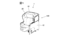
- FIG. 1 is a perspective view of a business sheet.
- FIG. 2 is a component configuration diagram of the divider.
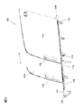
- FIG. 3 is an explanatory diagram showing the overall configuration of the divider.
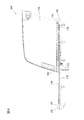
- FIG. 4 is an explanatory diagram showing the overall configuration of the divider.
- FIG. 5 is an explanatory diagram of a main part of the divider.
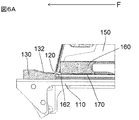
- FIG. 6A is an explanatory diagram showing the operation of the divider.
- FIG. 6B is an explanatory diagram showing the operation of the divider.
- FIG. 6C is an explanatory diagram showing the operation of the divider.
- an aircraft passenger seat 1 has a seat body 20 surrounded by a back shell 10 and a side shell 12, and the side shell 12 between a pair of passenger seats 1 arranged adjacent to each other.
- Divider unit 100 is equipped.
- FIG. 2 shows a component structure of the divider unit 100, and a slide rail 120 is attached to the upper surface of the fixed frame 110 fixed to the side shell 12.
- the slide rail 120 is a C-channel rail having a groove at the top and flange portions 122 on both sides.
- the divider 150 is a plate-like member, and slides in the slide rail 120 by the two linear guides 170.
- the linear guide 170 has a downward T-shape, has a guide portion that expands on both sides, and is inserted inside the flange portion 122 of the slide rail 120.
- the front end side stopper 130 and the rear end side stopper 140 are attached to the front end and the rear end of the slide rail 120, respectively.
- the upper surface of the front end side stopper 130 is formed on the tapered surface 132
- the upper surface of the rear end side stopper 140 is formed on the tapered surface 142.
- FIG. 3 shows a state in which the passenger grips the handle 152 of the divider 150 and slides it in the direction of arrow F. By pulling the divider 150 forward, the space between the adjacent seats is partitioned and privacy is improved.
- FIG. 4 shows a structure in which a divider frame 160 is provided below the divider 150.
- FIG. 5 shows details of the lower part of the tip of the divider 150.
- a linear guide 170 is fixed to the lower part of the divider frame 160.
- FIGS. 6A to 6C show the action of sliding the divider 150 in the direction of arrow F to close the divider 150.
- the front end portion of the tapered surface 132 of the front end side stopper 130 is the lower end portion of the frame front end of the divider frame 160. Since it is set at a position lower than 162, the frame front end lower surface portion 162 of the divider frame 160 rides on the tapered surface 132 of the front end side stopper 130 as shown in FIG. 6B.
- the divider frame 160 tends to rise. However, since the linear guide 170 is in the slit of the slide rail 120 and the linear guide 170 and the flange portion 122 of the slide rail 120 interfere with each other, the ascent is restricted.
- the frame front end lower surface portion 162 of the divider frame 160 is gradually decelerated by the frictional force with the tapered surface 132 of the front end side stopper 130, and the forward movement of the divider 150 stops.
- the divider frame 160 of the divider 150 and the front end side stopper 130 are prevented from stopping due to a collision, and the generation of noise is prevented.
Landscapes
- Engineering & Computer Science (AREA)
- Aviation & Aerospace Engineering (AREA)
- Seats For Vehicles (AREA)
- Passenger Equipment (AREA)
Abstract
This divider unit (100) for a passenger seat has a slide rail (120) that is fixed onto a side shell (12) that surrounds the seat. A plate-like divider (150) is equipped with two linear guides (170) inserted in the slide rail (120) and slides within the slide rail (120). A stopper (130) attached to the front end of the slide rail (120) has a tapered surface (132), and the divider (150) is stopped when the front end of the divider (150) rides over the tapered surface (132), thereby preventing the generation of an impact sound.
Description
本発明は、航空機の客室内に配置されるビジネスクラス用シート(座席)等に装備されるディバイダーと称する仕切板のユニットに関する。
The present invention relates to a partition plate unit called a divider installed in a business class seat (seat) or the like placed in an aircraft cabin.
ビジネスクラスのシートにあっては、シェルと称する囲いの内部に、リクライニングシートを収容したものを、2座席分並べて配置するものがある。
この種のシートは、隣のシートの間にスライド式のディバイダーを設けてプライバシーの向上を図っていた。 In business class seats, there is a seat in which a reclining seat is accommodated in an enclosure called a shell, arranged side by side for two seats.
This type of seat is designed to improve privacy by providing a sliding divider between adjacent seats.
航空機のシートは離着陸時には、リクライニング、テーブルなどを初期の状態に戻す必要がある。ディバイダーは離着陸時には収納された状態(初期の状態)とし、使用時には前方にスライドさせてストッパーに当接させ閉めて閉空間を作る。この場合、ディバイダーは、衝突時の強度要求を満たすために剛性の高いストッパーで停止させる構造を備えるが、通常の使用時には高い剛性のストッパーとの衝突音が大きく、プライバシーの確保の上では問題となる。
Aircraft seats must be reclined and returned to their initial state when taking off and landing. The divider is stored (initial state) when taking off and landing, and when used, it is slid forward and brought into contact with a stopper to close it to create a closed space. In this case, the divider is equipped with a structure that stops with a highly rigid stopper to meet the strength requirements at the time of collision, but during normal use, the sound of collision with the highly rigid stopper is loud, which is problematic in ensuring privacy. Become.
本発明の目的は上述した問題を解決する航空機のシート用のディバイダーユニットを提供するものである。
An object of the present invention is to provide a divider unit for an aircraft seat that solves the above-described problems.
上記目的を達成させるため、本発明の航空機の乗客用シートのディバイダーユニットは、シートを囲むサイドシェル上に固定されるスライドレールと、
スライドレール内に差し込まれる2つのリニアガイドに支持される板状のスライダーと、
スライドレールの前後端側にとりつけられるストッパーとを備え、
スライドレールは、上部にスリットを有する断面がCチャンネル形状の部材であり、
リニアガイドはスライドレールに差し込まれる下向きのT字形の部材であり、
少なくとも前端側ストッパーは、スライドレールの端部はスライダーの先端が乗り上げる高さであって、奥側が高くなるテーパー面を備えること、を特徴とする。 To achieve the above object, an aircraft passenger seat divider unit according to the present invention includes a slide rail fixed on a side shell surrounding the seat,
A plate-like slider supported by two linear guides inserted into the slide rail;
With stoppers attached to the front and rear ends of the slide rail,
The slide rail is a member having a C-channel cross section with a slit at the top,
The linear guide is a downward T-shaped member inserted into the slide rail.
At least the front end side stopper is characterized in that the end portion of the slide rail is provided with a tapered surface with a height at which the tip of the slider rides and a back side becomes higher.
また、ストッパーのテーパー面は凹形状の湾曲面で形成されることを特徴とする。
Also, the tapered surface of the stopper is formed by a concave curved surface.
本発明は以上の構成を備えることにより、ディバイダーを閉める際に、スライダーがストッパーに直接衝突せずフリクションにより衝撃を吸収し強度要求を満足する事が可能となる。また、この発明により、ディバイダーが徐々に停止するので、衝突音の発生を防止できる。
The present invention has the above-described configuration, so that when the divider is closed, the slider does not directly collide with the stopper, but the impact is absorbed by the friction and the strength requirement can be satisfied. Further, according to the present invention, since the divider is gradually stopped, it is possible to prevent the occurrence of a collision sound.
本発明の実施の形態を図面を参照しながら詳述する。
図1に示すように、航空機の乗客用シート1はバックシェル10,サイドシェル12に囲まれるシート本体20を有し、隣接して配置される一対の乗客用シート1の間のサイドシェル12にディバイダーユニット100が装備される。 Embodiments of the present invention will be described in detail with reference to the drawings.
As shown in FIG. 1, anaircraft passenger seat 1 has a seat body 20 surrounded by a back shell 10 and a side shell 12, and the side shell 12 between a pair of passenger seats 1 arranged adjacent to each other. Divider unit 100 is equipped.
図1に示すように、航空機の乗客用シート1はバックシェル10,サイドシェル12に囲まれるシート本体20を有し、隣接して配置される一対の乗客用シート1の間のサイドシェル12にディバイダーユニット100が装備される。 Embodiments of the present invention will be described in detail with reference to the drawings.
As shown in FIG. 1, an
図2はディバイダーユニット100の部品構成を示し、サイドシェル12に固定される固定フレーム110の上面にスライドレール120が取りつけられる。スライドレール120は上部に溝が開口し、両側にフランジ部122を有するCチャンネル形のレールである。
FIG. 2 shows a component structure of the divider unit 100, and a slide rail 120 is attached to the upper surface of the fixed frame 110 fixed to the side shell 12. The slide rail 120 is a C-channel rail having a groove at the top and flange portions 122 on both sides.
ディバイダー150は板状の部材であって、2個のリニアガイド170によりスライドレール120内を摺動する。リニアガイド170は下向きのT字形状であって、両側に拡がる案内部を有し、スライドレール120のフランジ部122の内側に差し込まれる。
The divider 150 is a plate-like member, and slides in the slide rail 120 by the two linear guides 170. The linear guide 170 has a downward T-shape, has a guide portion that expands on both sides, and is inserted inside the flange portion 122 of the slide rail 120.
スライドレール120の前端と後端には、それぞれ前端側ストッパー130,後端側ストッパー140がとりつけられる。前端側ストッパー130の上面はテーパー面132に形成され、後端側ストッパー140の上面はテーパー面142に形成される。
The front end side stopper 130 and the rear end side stopper 140 are attached to the front end and the rear end of the slide rail 120, respectively. The upper surface of the front end side stopper 130 is formed on the tapered surface 132, and the upper surface of the rear end side stopper 140 is formed on the tapered surface 142.
図3は乗客がディバイダー150のハンドル152を把持して矢印F方向に摺動させる状態を示す。
ディバイダー150を前方に引き出すことにより、隣席との間が仕切られて、プライバシーが向上する。 FIG. 3 shows a state in which the passenger grips thehandle 152 of the divider 150 and slides it in the direction of arrow F.
By pulling thedivider 150 forward, the space between the adjacent seats is partitioned and privacy is improved.
ディバイダー150を前方に引き出すことにより、隣席との間が仕切られて、プライバシーが向上する。 FIG. 3 shows a state in which the passenger grips the
By pulling the
図4はディバイダー150の下部にディバイダーフレーム160が備えられる構造を示す。
板状のディバイダー150の下部にディバイダーフレーム160を取り付けることで、剛性が向上する。 FIG. 4 shows a structure in which adivider frame 160 is provided below the divider 150.
By attaching thedivider frame 160 to the lower part of the plate-like divider 150, the rigidity is improved.
板状のディバイダー150の下部にディバイダーフレーム160を取り付けることで、剛性が向上する。 FIG. 4 shows a structure in which a
By attaching the
図5はディバイダー150の先端下部の詳細を示す。
ディバイダーフレーム160の下部にリニアガイド170が固定される。 FIG. 5 shows details of the lower part of the tip of thedivider 150.
Alinear guide 170 is fixed to the lower part of the divider frame 160.
ディバイダーフレーム160の下部にリニアガイド170が固定される。 FIG. 5 shows details of the lower part of the tip of the
A
図6Aから図6Cはディバイダー150を矢印F方向に摺動してディバイダー150を閉じる作用を示す。
FIGS. 6A to 6C show the action of sliding the divider 150 in the direction of arrow F to close the divider 150. FIG.
ディバイダー150がスライドレール120上を摺動してディバイダーフレーム160のフレーム先端下面部162が前端側ストッパー130に近接すると、前端側ストッパー130のテーパー面132の先端部はディバイダーフレーム160のフレーム先端下面部162よりも低い位置に設定されているので、ディバイダーフレーム160のフレーム先端下面部162は図6Bに示すように、前端側ストッパー130のテーパー面132に乗り上げる。
When the divider 150 slides on the slide rail 120 and the frame front end lower surface portion 162 of the divider frame 160 comes close to the front end side stopper 130, the front end portion of the tapered surface 132 of the front end side stopper 130 is the lower end portion of the frame front end of the divider frame 160. Since it is set at a position lower than 162, the frame front end lower surface portion 162 of the divider frame 160 rides on the tapered surface 132 of the front end side stopper 130 as shown in FIG. 6B.
テーパー面132は奥に行くに従い高さ位置が増大するので、ディバイダーフレーム160は上昇しようとする。しかしながら、リニアガイド170はスライドレール120のスリット内にあって、リニアガイド170とスライドレール120のフランジ部122は干渉するので、上昇は規制される。
Since the height position of the tapered surface 132 increases as it goes further, the divider frame 160 tends to rise. However, since the linear guide 170 is in the slit of the slide rail 120 and the linear guide 170 and the flange portion 122 of the slide rail 120 interfere with each other, the ascent is restricted.
そこで、ディバイダーフレーム160のフレーム先端下面部162は前端側ストッパー130のテーパー面132との間で摩擦力により徐々に減速され、ディバイダー150の前方への移動は停止する。
Therefore, the frame front end lower surface portion 162 of the divider frame 160 is gradually decelerated by the frictional force with the tapered surface 132 of the front end side stopper 130, and the forward movement of the divider 150 stops.
この作用により、ディバイダー150のディバイダーフレーム160と前端側ストッパー130は衝突により停止することが避けられ、ノイズの発生は防止される。
By this action, the divider frame 160 of the divider 150 and the front end side stopper 130 are prevented from stopping due to a collision, and the generation of noise is prevented.
1 航空機の乗客用シート
10 バックシェル
12 サイドシェル
20 シート本体
100 ディバイダーユニット
110 固定フレーム
120 スライドレール
122 フランジ部
130 前端側ストッパー
132 テーパー面
140 後端側ストッパー
142 テーパー面
150 ディバイダー
152 ハンドル
160 ディバイダーフレーム
162 フレーム先端下面部
170 リニアガイド
DESCRIPTION OFSYMBOLS 1 Aircraft passenger seat 10 Back shell 12 Side shell 20 Seat main body 100 Divider unit 110 Fixed frame 120 Slide rail 122 Flange portion 130 Front end side stopper 132 Tapered surface 140 Rear end side stopper 142 Tapered surface 150 Divider 152 Handle 160 Divider frame 162 Frame tip bottom surface 170 Linear guide
10 バックシェル
12 サイドシェル
20 シート本体
100 ディバイダーユニット
110 固定フレーム
120 スライドレール
122 フランジ部
130 前端側ストッパー
132 テーパー面
140 後端側ストッパー
142 テーパー面
150 ディバイダー
152 ハンドル
160 ディバイダーフレーム
162 フレーム先端下面部
170 リニアガイド
DESCRIPTION OF
Claims (2)
- 並列に配置される航空機の乗客用シートの間に配置されるスライド型のディバイダーユニットであって、
シートを囲むサイドシェル上に固定されるスライドレールと、
スライドレール内に差し込まれる2つのリニアガイドに支持される板状のスライダーと、
スライドレールの前後端側にとりつけられるストッパーとを備え、
スライドレールは、上部にスリットを有する断面がCチャンネル形状の部材であり、
リニアガイドはスライドレールに差し込まれる下向きのT字形の部材であり、
少なくとも前端側ストッパーは、スライドレールの端部はスライダーの先端が乗り上げる高さであって、奥側が高くなるテーパー面を備えること、
を特徴とする航空機の乗客用シートのディバイダーユニット。 A slide-type divider unit arranged between passenger seats of aircraft arranged in parallel,
A slide rail fixed on the side shell surrounding the seat;
A plate-like slider supported by two linear guides inserted into the slide rail;
With stoppers attached to the front and rear ends of the slide rail,
The slide rail is a member having a C-channel cross section with a slit at the top,
The linear guide is a downward T-shaped member inserted into the slide rail.
At least the front end side stopper has a tapered surface where the end of the slide rail is at a height where the tip of the slider rides and the back side becomes higher,
Divider unit for passenger seats of aircraft. - ストッパーのテーパー面は凹形状の湾曲面で形成されることを特徴とする請求項1記載のディバイダーユニット。 The divider unit according to claim 1, wherein the tapered surface of the stopper is formed of a concave curved surface.
Priority Applications (2)
| Application Number | Priority Date | Filing Date | Title |
|---|---|---|---|
| EP14869915.0A EP3081490B1 (en) | 2013-12-09 | 2014-04-11 | Divider unit for aircraft passenger seat |
| US15/102,219 US9567085B2 (en) | 2013-12-09 | 2014-04-11 | Divider unit for aircraft passenger seat |
Applications Claiming Priority (2)
| Application Number | Priority Date | Filing Date | Title |
|---|---|---|---|
| JP2013254187A JP5721807B1 (en) | 2013-12-09 | 2013-12-09 | Splitter unit for aircraft passenger seat |
| JP2013-254187 | 2013-12-09 |
Publications (1)
| Publication Number | Publication Date |
|---|---|
| WO2015087559A1 true WO2015087559A1 (en) | 2015-06-18 |
Family
ID=53277885
Family Applications (1)
| Application Number | Title | Priority Date | Filing Date |
|---|---|---|---|
| PCT/JP2014/060525 WO2015087559A1 (en) | 2013-12-09 | 2014-04-11 | Divider unit for aircraft passenger seat |
Country Status (4)
| Country | Link |
|---|---|
| US (1) | US9567085B2 (en) |
| EP (1) | EP3081490B1 (en) |
| JP (1) | JP5721807B1 (en) |
| WO (1) | WO2015087559A1 (en) |
Families Citing this family (6)
| Publication number | Priority date | Publication date | Assignee | Title |
|---|---|---|---|---|
| WO2016164564A1 (en) * | 2015-04-07 | 2016-10-13 | B/E Aerospace, Inc. | Privacy divider for adjacent parallel passenger seats |
| GB2555123B (en) * | 2016-10-19 | 2020-04-29 | Thompson Aero Seating Ltd | Passenger seating with partition assembly |
| US10494101B2 (en) * | 2017-08-23 | 2019-12-03 | Rockwell Collins, Inc. | Passenger seat privacy headrest |
| US10611314B2 (en) * | 2017-09-29 | 2020-04-07 | Faurecia Automotive Seating, Llc | Vehicle privacy screen |
| US10479506B1 (en) * | 2018-05-25 | 2019-11-19 | The Boeing Company | Deployable partition systems and methods for seat assemblies |
| US11034454B1 (en) | 2019-11-06 | 2021-06-15 | B/E Aerospace, Inc. | Seat spreader mounted seat privacy closeout |
Citations (4)
| Publication number | Priority date | Publication date | Assignee | Title |
|---|---|---|---|---|
| JP2005536390A (en) | 2002-08-23 | 2005-12-02 | エールブユス | Aircraft cabin internal layout |
| JP2008520480A (en) * | 2004-11-17 | 2008-06-19 | プレミアム・エアクラフト・インテリアーズ・ユーケイ・リミテッド | Aircraft seat |
| JP2011511739A (en) | 2008-02-11 | 2011-04-14 | ビーイー・エアロスペース・インコーポレーテッド | Aircraft cabin class dividers |
| JP2012529677A (en) | 2009-06-08 | 2012-11-22 | ビー イー エアロスペイス,インク. | Contact-responsive privacy partition |
Family Cites Families (10)
| Publication number | Priority date | Publication date | Assignee | Title |
|---|---|---|---|---|
| DE19541567C1 (en) * | 1995-11-08 | 1997-01-23 | Keiper Recaro Gmbh Co | Vehicle seat with partition, esp. for aircraft or bus passengers |
| US20010000639A1 (en) * | 1997-02-20 | 2001-05-03 | Singapore Airlines Ltd. | Transport accommodation |
| ES2239461T3 (en) * | 1998-10-15 | 2005-09-16 | British Airways Plc | ONE SEAT UNIT. |
| DE10358478B4 (en) * | 2003-12-11 | 2012-03-08 | Recaro Aircraft Seating Gmbh & Co. Kg | Passenger seating |
| DE102004061471B4 (en) * | 2004-12-21 | 2007-09-06 | Recaro Aircraft Seating Gmbh & Co. Kg | Passenger seat, in particular passenger seat, and passenger seating group, in particular passenger seating group |
| DE102004063094B4 (en) * | 2004-12-22 | 2010-05-12 | Airbus Deutschland Gmbh | Passenger seating unit, in particular for commercial aircraft |
| DE102008052841B4 (en) * | 2008-10-22 | 2011-03-31 | Airbus Operations Gmbh | Screening of passenger seats in an aircraft |
| JP6058008B2 (en) * | 2011-09-02 | 2017-01-11 | ゾディアック シーツ フランス | Advanced seat with retractable food tray and sliding armrest |
| US9266614B2 (en) * | 2012-08-01 | 2016-02-23 | B/E Aerospace, Inc. | Passenger suite seating arrangement with moveable video monitor |
| US9216674B1 (en) * | 2014-10-09 | 2015-12-22 | Rebecca A. Garib | Portable seat partition unit |
-
2013
- 2013-12-09 JP JP2013254187A patent/JP5721807B1/en active Active
-
2014
- 2014-04-11 WO PCT/JP2014/060525 patent/WO2015087559A1/en active Application Filing
- 2014-04-11 US US15/102,219 patent/US9567085B2/en active Active
- 2014-04-11 EP EP14869915.0A patent/EP3081490B1/en active Active
Patent Citations (4)
| Publication number | Priority date | Publication date | Assignee | Title |
|---|---|---|---|---|
| JP2005536390A (en) | 2002-08-23 | 2005-12-02 | エールブユス | Aircraft cabin internal layout |
| JP2008520480A (en) * | 2004-11-17 | 2008-06-19 | プレミアム・エアクラフト・インテリアーズ・ユーケイ・リミテッド | Aircraft seat |
| JP2011511739A (en) | 2008-02-11 | 2011-04-14 | ビーイー・エアロスペース・インコーポレーテッド | Aircraft cabin class dividers |
| JP2012529677A (en) | 2009-06-08 | 2012-11-22 | ビー イー エアロスペイス,インク. | Contact-responsive privacy partition |
Also Published As
| Publication number | Publication date |
|---|---|
| EP3081490B1 (en) | 2017-11-29 |
| US20160368608A1 (en) | 2016-12-22 |
| US9567085B2 (en) | 2017-02-14 |
| JP2015112909A (en) | 2015-06-22 |
| EP3081490A1 (en) | 2016-10-19 |
| EP3081490A4 (en) | 2016-11-02 |
| JP5721807B1 (en) | 2015-05-20 |
Similar Documents
| Publication | Publication Date | Title |
|---|---|---|
| WO2015087559A1 (en) | Divider unit for aircraft passenger seat | |
| CN104735944B (en) | For the adjustable bracket of sliding rail assembly | |
| FR3059951B1 (en) | ARRANGEMENT OF INDIVIDUAL SEATS FOR AIRCRAFT PASSENGERS | |
| CN102785593A (en) | Locking device of seat rail of vehicle | |
| EP3393906A1 (en) | Passenger seat having a displaceable seat element | |
| JP2013169945A (en) | Headrest for vehicle seat | |
| JP2009073398A (en) | Seat slide device for vehicle | |
| US20170120844A1 (en) | Side door trim for vehicle | |
| CN104512308B (en) | Vehicle seat | |
| CN109250120A (en) | The seat labyrinth component of aircraft | |
| JP2017094958A (en) | Seat support mechanism | |
| JP6265023B2 (en) | Window opening / closing device for vehicle door window | |
| JP6112561B2 (en) | Console Box | |
| JP2008110148A (en) | Table | |
| JP5938128B1 (en) | Drawer with tray | |
| JP6393631B2 (en) | Pull-out device for vehicle | |
| KR20060016350A (en) | Guide structure of tray | |
| JP2017202736A (en) | Seat slide device | |
| JP2008056082A (en) | Cabinet device | |
| JP6357135B2 (en) | Railway vehicle | |
| JP2016168869A (en) | Support structure of step trim | |
| JP5649712B2 (en) | Seat slide device | |
| JP7354785B2 (en) | wagon | |
| JP6227886B2 (en) | Console Box | |
| JP2012153210A (en) | Vehicle seat |
Legal Events
| Date | Code | Title | Description |
|---|---|---|---|
| 121 | Ep: the epo has been informed by wipo that ep was designated in this application |
Ref document number: 14869915 Country of ref document: EP Kind code of ref document: A1 |
|
| REEP | Request for entry into the european phase |
Ref document number: 2014869915 Country of ref document: EP |
|
| WWE | Wipo information: entry into national phase |
Ref document number: 15102219 Country of ref document: US Ref document number: 2014869915 Country of ref document: EP |
|
| NENP | Non-entry into the national phase |
Ref country code: DE |