WO2015083534A1 - 人体検知装置 - Google Patents
人体検知装置 Download PDFInfo
- Publication number
- WO2015083534A1 WO2015083534A1 PCT/JP2014/080420 JP2014080420W WO2015083534A1 WO 2015083534 A1 WO2015083534 A1 WO 2015083534A1 JP 2014080420 W JP2014080420 W JP 2014080420W WO 2015083534 A1 WO2015083534 A1 WO 2015083534A1
- Authority
- WO
- WIPO (PCT)
- Prior art keywords
- human body
- detection sensor
- mounting member
- detection
- attached
- Prior art date
Links
Images

Classifications
-
- A—HUMAN NECESSITIES
- A61—MEDICAL OR VETERINARY SCIENCE; HYGIENE
- A61B—DIAGNOSIS; SURGERY; IDENTIFICATION
- A61B5/00—Measuring for diagnostic purposes; Identification of persons
- A61B5/103—Detecting, measuring or recording devices for testing the shape, pattern, colour, size or movement of the body or parts thereof, for diagnostic purposes
- A61B5/11—Measuring movement of the entire body or parts thereof, e.g. head or hand tremor, mobility of a limb
-
- A—HUMAN NECESSITIES
- A61—MEDICAL OR VETERINARY SCIENCE; HYGIENE
- A61B—DIAGNOSIS; SURGERY; IDENTIFICATION
- A61B5/00—Measuring for diagnostic purposes; Identification of persons
- A61B5/103—Detecting, measuring or recording devices for testing the shape, pattern, colour, size or movement of the body or parts thereof, for diagnostic purposes
- A61B5/107—Measuring physical dimensions, e.g. size of the entire body or parts thereof
-
- A—HUMAN NECESSITIES
- A61—MEDICAL OR VETERINARY SCIENCE; HYGIENE
- A61B—DIAGNOSIS; SURGERY; IDENTIFICATION
- A61B5/00—Measuring for diagnostic purposes; Identification of persons
- A61B5/68—Arrangements of detecting, measuring or recording means, e.g. sensors, in relation to patient
- A61B5/6801—Arrangements of detecting, measuring or recording means, e.g. sensors, in relation to patient specially adapted to be attached to or worn on the body surface
- A61B5/6802—Sensor mounted on worn items
- A61B5/6811—External prosthesis
-
- A—HUMAN NECESSITIES
- A61—MEDICAL OR VETERINARY SCIENCE; HYGIENE
- A61F—FILTERS IMPLANTABLE INTO BLOOD VESSELS; PROSTHESES; DEVICES PROVIDING PATENCY TO, OR PREVENTING COLLAPSING OF, TUBULAR STRUCTURES OF THE BODY, e.g. STENTS; ORTHOPAEDIC, NURSING OR CONTRACEPTIVE DEVICES; FOMENTATION; TREATMENT OR PROTECTION OF EYES OR EARS; BANDAGES, DRESSINGS OR ABSORBENT PADS; FIRST-AID KITS
- A61F2/00—Filters implantable into blood vessels; Prostheses, i.e. artificial substitutes or replacements for parts of the body; Appliances for connecting them with the body; Devices providing patency to, or preventing collapsing of, tubular structures of the body, e.g. stents
- A61F2/50—Prostheses not implantable in the body
- A61F2/68—Operating or control means
- A61F2/70—Operating or control means electrical
- A61F2/72—Bioelectric control, e.g. myoelectric
-
- A—HUMAN NECESSITIES
- A61—MEDICAL OR VETERINARY SCIENCE; HYGIENE
- A61F—FILTERS IMPLANTABLE INTO BLOOD VESSELS; PROSTHESES; DEVICES PROVIDING PATENCY TO, OR PREVENTING COLLAPSING OF, TUBULAR STRUCTURES OF THE BODY, e.g. STENTS; ORTHOPAEDIC, NURSING OR CONTRACEPTIVE DEVICES; FOMENTATION; TREATMENT OR PROTECTION OF EYES OR EARS; BANDAGES, DRESSINGS OR ABSORBENT PADS; FIRST-AID KITS
- A61F2/00—Filters implantable into blood vessels; Prostheses, i.e. artificial substitutes or replacements for parts of the body; Appliances for connecting them with the body; Devices providing patency to, or preventing collapsing of, tubular structures of the body, e.g. stents
- A61F2/50—Prostheses not implantable in the body
- A61F2/76—Means for assembling, fitting or testing prostheses, e.g. for measuring or balancing, e.g. alignment means
-
- A—HUMAN NECESSITIES
- A61—MEDICAL OR VETERINARY SCIENCE; HYGIENE
- A61F—FILTERS IMPLANTABLE INTO BLOOD VESSELS; PROSTHESES; DEVICES PROVIDING PATENCY TO, OR PREVENTING COLLAPSING OF, TUBULAR STRUCTURES OF THE BODY, e.g. STENTS; ORTHOPAEDIC, NURSING OR CONTRACEPTIVE DEVICES; FOMENTATION; TREATMENT OR PROTECTION OF EYES OR EARS; BANDAGES, DRESSINGS OR ABSORBENT PADS; FIRST-AID KITS
- A61F2/00—Filters implantable into blood vessels; Prostheses, i.e. artificial substitutes or replacements for parts of the body; Appliances for connecting them with the body; Devices providing patency to, or preventing collapsing of, tubular structures of the body, e.g. stents
- A61F2/50—Prostheses not implantable in the body
- A61F2/54—Artificial arms or hands or parts thereof
- A61F2/58—Elbows; Wrists ; Other joints; Hands
- A61F2/583—Hands; Wrist joints
- A61F2/588—Hands having holding devices shaped differently from human fingers, e.g. claws, hooks, tubes
-
- A—HUMAN NECESSITIES
- A61—MEDICAL OR VETERINARY SCIENCE; HYGIENE
- A61F—FILTERS IMPLANTABLE INTO BLOOD VESSELS; PROSTHESES; DEVICES PROVIDING PATENCY TO, OR PREVENTING COLLAPSING OF, TUBULAR STRUCTURES OF THE BODY, e.g. STENTS; ORTHOPAEDIC, NURSING OR CONTRACEPTIVE DEVICES; FOMENTATION; TREATMENT OR PROTECTION OF EYES OR EARS; BANDAGES, DRESSINGS OR ABSORBENT PADS; FIRST-AID KITS
- A61F2/00—Filters implantable into blood vessels; Prostheses, i.e. artificial substitutes or replacements for parts of the body; Appliances for connecting them with the body; Devices providing patency to, or preventing collapsing of, tubular structures of the body, e.g. stents
- A61F2/50—Prostheses not implantable in the body
- A61F2/68—Operating or control means
- A61F2/70—Operating or control means electrical
- A61F2002/701—Operating or control means electrical operated by electrically controlled means, e.g. solenoids or torque motors
-
- A—HUMAN NECESSITIES
- A61—MEDICAL OR VETERINARY SCIENCE; HYGIENE
- A61F—FILTERS IMPLANTABLE INTO BLOOD VESSELS; PROSTHESES; DEVICES PROVIDING PATENCY TO, OR PREVENTING COLLAPSING OF, TUBULAR STRUCTURES OF THE BODY, e.g. STENTS; ORTHOPAEDIC, NURSING OR CONTRACEPTIVE DEVICES; FOMENTATION; TREATMENT OR PROTECTION OF EYES OR EARS; BANDAGES, DRESSINGS OR ABSORBENT PADS; FIRST-AID KITS
- A61F2/00—Filters implantable into blood vessels; Prostheses, i.e. artificial substitutes or replacements for parts of the body; Appliances for connecting them with the body; Devices providing patency to, or preventing collapsing of, tubular structures of the body, e.g. stents
- A61F2/50—Prostheses not implantable in the body
- A61F2/76—Means for assembling, fitting or testing prostheses, e.g. for measuring or balancing, e.g. alignment means
- A61F2002/7615—Measuring means
- A61F2002/7635—Measuring means for measuring force, pressure or mechanical tension
-
- A—HUMAN NECESSITIES
- A61—MEDICAL OR VETERINARY SCIENCE; HYGIENE
- A61F—FILTERS IMPLANTABLE INTO BLOOD VESSELS; PROSTHESES; DEVICES PROVIDING PATENCY TO, OR PREVENTING COLLAPSING OF, TUBULAR STRUCTURES OF THE BODY, e.g. STENTS; ORTHOPAEDIC, NURSING OR CONTRACEPTIVE DEVICES; FOMENTATION; TREATMENT OR PROTECTION OF EYES OR EARS; BANDAGES, DRESSINGS OR ABSORBENT PADS; FIRST-AID KITS
- A61F2/00—Filters implantable into blood vessels; Prostheses, i.e. artificial substitutes or replacements for parts of the body; Appliances for connecting them with the body; Devices providing patency to, or preventing collapsing of, tubular structures of the body, e.g. stents
- A61F2/50—Prostheses not implantable in the body
- A61F2/76—Means for assembling, fitting or testing prostheses, e.g. for measuring or balancing, e.g. alignment means
- A61F2002/7615—Measuring means
- A61F2002/764—Measuring means for measuring acceleration
-
- A—HUMAN NECESSITIES
- A61—MEDICAL OR VETERINARY SCIENCE; HYGIENE
- A61F—FILTERS IMPLANTABLE INTO BLOOD VESSELS; PROSTHESES; DEVICES PROVIDING PATENCY TO, OR PREVENTING COLLAPSING OF, TUBULAR STRUCTURES OF THE BODY, e.g. STENTS; ORTHOPAEDIC, NURSING OR CONTRACEPTIVE DEVICES; FOMENTATION; TREATMENT OR PROTECTION OF EYES OR EARS; BANDAGES, DRESSINGS OR ABSORBENT PADS; FIRST-AID KITS
- A61F2/00—Filters implantable into blood vessels; Prostheses, i.e. artificial substitutes or replacements for parts of the body; Appliances for connecting them with the body; Devices providing patency to, or preventing collapsing of, tubular structures of the body, e.g. stents
- A61F2/50—Prostheses not implantable in the body
- A61F2/76—Means for assembling, fitting or testing prostheses, e.g. for measuring or balancing, e.g. alignment means
- A61F2002/7615—Measuring means
- A61F2002/7645—Measuring means for measuring torque, e.g. hinge or turning moment, moment of force
Definitions
- the present invention relates to a human body detection device that detects a movement of a worn part by being worn on a human body and outputs a control signal for controlling a control target such as a prosthetic limb or an assist device.
- control signal for controlling the motor (control target) for opening and closing the hand of the electric prosthetic hand it is attached to the forearm part of the human body where the electric prosthetic hand is worn, and is sent from the brain to move the muscle
- a myoelectric sensor that detects a signal (surface myoelectric potential) and outputs it as a control signal has been proposed (Patent Document 1).
- the human body detection device has a sheet-like base portion having flexibility, and is attached to one surface of the base portion so as to be detachably attached to the human body surface.
- a sheet-like adhesive portion, and a mounting member that is attached between the adhesive portion and the base portion and has a flat support portion that bends along the surface of the human body, and is attached between joints in the human body
- a detection sensor that is attached to the mounting member and detects a movement of a part of the human body where the mounting member is mounted, and a detection signal from the detection sensor is converted into a control signal for controlling a control target
- an output unit for outputting the output.
- Examples of the flexible sheet-like “base portion” include “foamed resin sheet”, “rubber sheet”, “silicone resin sheet”, “woven fabric”, and “nonwoven fabric”. it can.
- examples of the “adhesive part” include “hydrophilic gel sheet”, “hydrophobic gel sheet”, “conductive gel sheet”, and the like.
- examples of the material of the “adhesive part” include “silicone resin”, “acrylic resin”, “rubber”, “urethane resin”, and the like.
- the “support portion” may be any one that does not cause wrinkles (thickness) when bent (bent), such as “metal plate such as stainless steel or aluminum alloy”, “synthetic resin plate”, “cardboard” , Etc. can be illustrated.
- between joints includes “between shoulder and elbow joints”, “between elbow joints and wrist joints”, “tip side from wrist joints”, “between hip joints and knee joints”, “knee joints” "Between the joint and ankle joint”, “Toe side more than the ankle joint”, “Between shoulder joint and hip joint”, “Cranial side rather than neck (cervical vertebra)", “Between neck joint and hip joint (torso)” Can be exemplified.
- the “mounting member” includes a “mounting member having a flexible sheet-like base portion and an adhesive portion that is bonded to one surface of the base portion and is attached to the surface of the human body.
- detection sensor strain sensor
- acceleration sensor acceleration sensor
- pressure sensor pressure sensor
- gyro sensor gyroscope
- potentialometer light irradiated from the light emitting part to the human body surface
- optical sensor and the” vibration sensor “that detect the movement by receiving light at the unit.
- a plurality of detection sensors may be provided. In this case, different types of sensors may be used, or the same type of sensors may be used.
- examples of the part where the detection sensor is mounted on the mounting member include “between the base part and the support part”, “between the adhesive part and the support part”, “the opposite side of the base part from the adhesive part”, etc. can do.
- the “output unit” includes “having an amplification circuit that amplifies the detection signal from the detection sensor”, “removes noise from the detection signal from the detection sensor, or exceeds a specific frequency (motion) or threshold value. “Having a filter circuit for taking out a detection signal or the like”, “having a determination circuit for determining whether or not the detection signal from the detection sensor exceeds a preset threshold value”, “detection sensor "Having an arithmetic circuit that performs arithmetic processing on the detection signal by”, “having a sensor drive circuit for driving the detection sensor”, “the detection signal from the detection sensor as a control signal as it is What is output ”can be exemplified.
- the “output unit” may output the detection signals from the plurality of detection sensors as separate control signals, or output the detection signals from the plurality of detection sensors as a single control signal. You may make it let it.
- control target includes “prosthetic limbs driven by a driving source (electrically prosthetic hand, electric prosthetic leg, etc.)”, “power assist suit”, “wheelchair”, “tool”, “care device”, “personal computer” Can be exemplified.
- the detection sensor when detecting a change in the shape of the surface of the human body as the movement of the portion of the human body where the mounting member is mounted, the surface of the human body when the shape of the human body surface is changed, or the base portion or the adhesive portion of the mounting member , Partial irregularities such as wrinkles may occur. And if the detection sensor detects the unevenness caused by the change in the shape of the human body surface, it outputs a detection signal different from the overall (average) shape change in the detection area by the detection sensor on the human body surface, There is a risk that the controlled object will malfunction.
- the mounting member to which the detection sensor is attached is attached to the surface of the human body between the joints of the human body by the adhesive portion, for example, a belt-shaped mounting member is wound around the human body and mounted.
- the mounting member does not move relative to the human body. Accordingly, it is possible to prevent the detection sensor from being displaced relative to the human body, and to reliably detect the movement of the portion of the human body where the mounting member is mounted.
- the position shift of a detection sensor can be prevented, the erroneous detection by position shift can be suppressed, and the malfunctioning of a control object can be reduced.
- the mounting member can be mounted by sticking the adhesive part to the surface of the human body, for example, as compared with the case where the mounting member is mounted as a band-shaped member using a hook-and-loop fastener or a buckle, Even with one hand, the mounting member can be attached to the surface of the human body and easily mounted, making it easy to use.
- the support part since a flat support part that bends along the human body surface is provided between the base part and the adhesive part of the mounting member, if the shape of the human body surface is changed, the support part responds to the shape change of the human body surface. Thus, it bends smoothly (the shape changes) without causing irregularities such as partial wrinkles. And by making the shape change of this support part be detected by a detection sensor, the surface of the human body can be detected without detecting irregularities such as wrinkles generated on the human body surface, base part, adhesive part, etc. Therefore, it is possible to reliably output a detection signal corresponding to the shape change of the control object, and to reduce malfunctions of the controlled object due to erroneous detection.
- the detection sensor is constituted by a plurality of detection sensors, and the plurality of detection sensors respectively detect different movements in a part of the human body where the mounting member is mounted.
- the detection sensor when the user performs a certain movement between the joints to which the plurality of detection sensors are attached via the mounting member, only the detection sensor corresponding to the certain movement among the plurality of detection sensors. The movement is detected, and the detection signal is converted into a control signal for controlling the controlled object and output.
- a detection sensor that does not correspond to a certain movement does not detect a certain movement, so that a control signal related to these detection sensors is not output.
- the detection sensor corresponding to a specific movement detects the movement and outputs a control signal between the joints of the human body wearing the mounting member, so that other detection sensors do not misdetect.
- the detection sensor is configured by a plurality of detection sensors as described above, a plurality of detection sensors that detect different movements do not detect erroneously, so the user is wearing the mounting member.
- a plurality of different control signals that do not interfere with each other can be output to the control target. Accordingly, since a plurality of different control signals can be output, a more complicated input operation can be performed on the controlled object.
- the human body detection device of this configuration can be used for a control target that requires a complicated input operation.
- the detection sensor is configured by a plurality of detection sensors
- a plurality of different control signals are output as described above by mounting a mounting member to which the plurality of detection sensors are mounted between joints in the human body. Therefore, unlike the conventional technique such as Patent Document 2, it is not necessary to operate a switch that outputs another control signal by using a part such as an arm on the opposite side where the mounting member is not mounted. Therefore, an input operation can be performed on the control target only between the joints on which the mounting members are mounted, so that other parts of the human body can be used freely.
- the human body detection device may include: “The detection sensor is mounted between the base portion of the mounting member and the adhesive portion, and the mounting member is mounted.
- a first detection sensor that detects a change in the shape of the surface of the human body at a part that is attached, and an acceleration or angular velocity that is attached to the base part of the mounting member and that acts on the part of the human body where the mounting member is mounted It is good also as a characteristic that it is comprised with the 2nd detection sensor to do.
- the shape change of the human body surface “the shape change of the surface due to the movement of the bone (specifically, the forearm part between the elbow joint and the wrist joint or the lower leg between the knee joint and the ankle joint) "Surface shape change by moving the bones to twist between joints where two bones extend like a part)” and “Surface shape change by muscle stretching / contraction” can do.
- first detection sensor that detects a change in the shape of the human body surface
- first detection sensor that detects a change in the shape of the human body surface
- strain sensor a “pressure sensor”
- optical sensor that detects movement by irradiating light on the human body surface”.
- “second detection sensor” for detecting acceleration or angular velocity “acceleration sensor for detecting acceleration acting in three directions orthogonal to each other”, “acceleration sensor for detecting only acceleration acting in one direction”, “ “Gyro sensor” and “vibration sensor” can be exemplified.
- the muscles between the joints are stretched and contracted, and if two bones extend between the joints, the bones should be twisted so that the two bones are twisted.
- the shape of the human body surface can be changed by moving it.
- muscles on the side of the body relative to the joints closer to the body between the joints for example, biceps, triceps, deltoid, biceps, quads, etc.
- acceleration can be applied between the joints.
- the first detection sensor detects the movement
- the acceleration is applied between the joints
- only the second detection sensor is detected.
- the movement is detected, and the first detection sensor and the second detection sensor can reliably detect different movements between the joints.
- the remaining detection sensors (The second detection sensor or the first detection sensor) will not be erroneously detected. Thereby, the malfunction of the controlled object due to erroneous detection can be reduced, and a human body detection device capable of reliably achieving the above-described effects can be realized.
- the human body detection device has, in addition to the above configuration, “The first detection sensor is for outputting a control signal for operating a control target from the output unit, and The second detection sensor is for causing the output unit to output a control signal for changing a control mode of a control target controlled by a control signal from the first detection sensor. " good.
- control mode “the operation mode in which the control object is operated by the detection signal from the first detection sensor”, “the hold mode in which the operation of the control object is stopped without receiving the detection signal from the first detection sensor”. ”,“ Correction mode for correcting the control target operation so that the detection signal from the first detection sensor has an arbitrary value as the origin ”,“ Correction / hold combining hold mode and correction mode Mode ", and the like.
- the first detection sensor used for outputting the control signal for operating the control target detects a change in the shape of the human body surface, there is no disordered part whose value changes rapidly. Since a detection signal represented by a smooth line can be output, the control target can be smoothly operated by using this detection signal as a control signal.
- the second detection sensor used for changing the control mode of the control target detects acceleration or angular velocity, the second detection sensor can output a detection signal represented by a line having a portion whose value changes rapidly. Therefore, it can be suitably used as a control signal (switch signal) for changing the control mode by utilizing a rapidly changing part, and the control mode to be controlled can be changed reliably. Therefore, it is possible to embody a human body detection device that can surely achieve the above-described effects.
- a human body detection apparatus 10 according to an embodiment of the present invention will be described in detail with reference to FIGS.
- This embodiment demonstrates the example which applied the human body detection apparatus 10 to the electric prosthesis 20 as a control object.
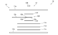
- the human body detection device 10 according to the present embodiment is mounted on the mounting member 11 that is mounted between the joints 2 in the human body 1 and the mounting member 11, and moves differently at a portion of the human body where the mounting member 11 is mounted.
- the mounting member 11 is mounted between the elbow joint 3 and the wrist joint (forearm 2a) as the joint 2 of the human body 1, as shown in FIG.
- the mounting member 11 is formed in a rectangular sheet shape (pad shape).
- the mounting member 11 is attached to a sheet-like base portion 11 a having flexibility and one surface of the base portion 11 a and is detachably attached to the surface of the human body.
- the base part 11a and the adhesive part 11b are formed in the same size, and are attached to each other by the adhesive force of the adhesive part 11b.
- the base part 11a is formed of a foamed resin sheet.
- the adhesion part 11b is formed of the hydrophilic gel sheet which consists of hydrophilic polymer.
- the mounting member 11 is attached between the base portion 11 a and the adhesive portion 11 b and is mounted on a flat plate-like support portion 11 c that bends in a curved shape, and a surface of the support portion 11 c on the base portion 11 a side.
- the support part 11c is smaller in size than the base part 11a and the adhesive part 11b.
- the support portion 11c is formed of a metal plate such as a stainless alloy or an aluminum alloy, a synthetic resin plate, cardboard, or the like so as not to cause wrinkles when bent.
- the first sheet 11d and the second sheet 11e are the same size as the support part 11c and are formed of a synthetic resin. These support part 11c, the 1st sheet
- seat 11e have an adhesion layer in the surface which faced at least the base part 11a among both surfaces.
- the pair of third sheets 11f is smaller in size than the support portion 11c and the like. These third sheets 11f are made of paper or synthetic resin, have an adhesive layer on the surfaces facing each other, and a release layer that weakens the adhesive force on the opposite surface. is doing.
- the plurality of detection sensors 12 includes a first detection sensor 12A that detects a change in the shape of the human body surface, and a second detection sensor 12B that detects acceleration acting on a part of the human body where the mounting member 11 is mounted. ing.
- the first detection sensor 12A is a strain sensor whose electric resistance value changes depending on the amount of bending. As shown in FIG. 2, the first detection sensor 12A includes a rectangular and flat sensor body 12a, a lead wire 12b extending outward from the sensor body 12a, and a cladding tube covering the lead wire 12b. 12c, and a covering portion 12d that covers the exposed lead wire 12b between the sensor body 12a and the covering tube 12c.
- the covering portion 12d is made of a thermoplastic resin and protects the lead wire 12b from being disconnected.
- the first detection sensor 12A is attached to the mounting member 11 between the base portion 11a and the adhesive portion 11b. Specifically, in the first detection sensor 12A, the sensor body 12a and the covering portion 12d are attached between the pair of third sheets 11f with the longitudinal direction of the sensor body 12a facing the same direction as the longitudinal direction of the mounting member 11. It has been.
- the first detection sensor 12A is attached such that the lead wire 12b covered with the cladding tube 12c extends outward from the long side of the mounting member 11 (see FIG. 1).
- the second detection sensor 12B detects acceleration acting in three directions orthogonal to each other. As shown in FIG. 1 and the like, the second detection sensor 12B is attached to the surface of the base portion 11a of the mounting member 11 opposite to the adhesive portion 11b.
- the second detection sensor 12B has a lead wire 12e covered with a cladding tube, and this lead wire 12e together with the cladding tube 12c of the first detection sensor 12A extends from the mounting member 11 to the external output unit 13. It extends.
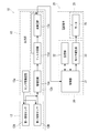
- the output unit 13 includes a sensor drive circuit 13a that supplies power for driving the detection sensor 12, and a conversion circuit 13b that converts a detection signal from the detection sensor 12 into a control signal. ing.
- the conversion circuit 13b amplifies the detection signal from the detection sensor 12, an filter circuit 13d that removes noise included in the detection signal or passes only a specific frequency, and the detection signal.
- an arithmetic circuit 13e that performs arithmetic processing.
- the output unit 13 is attached to the electric prosthesis 20.
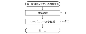
- the detection signal from the first detection sensor 12A is subjected to amplification processing (step S11) by the amplification circuit 13c as shown in FIG.
- step S12 the signal is converted into a control signal and output without passing through the arithmetic circuit 13e.
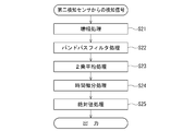
- the detection signal from the second detection sensor 12B is first subjected to amplification processing (step S21) in the amplification circuit 13c and then to band-pass filter processing in the filter circuit 13d. (Step S22) is performed. Subsequently, in the arithmetic circuit 13e, a mean square process (step S23) is performed for each of the three directions, and a time differentiation process (step S24) is performed for these values to obtain a jerk (acceleration time). Find the derivative). After that, absolute value processing (step S25) is performed on the jerk in each direction, and after adding them, it is converted into a control signal and output. As described above, the conversion circuit 13b according to the present embodiment converts the first detection sensor 12A and the second detection sensor 12B into control signals through different circuits.
- the electric prosthetic hand 20 includes a prosthetic hand attaching member 21 that covers the forearm portion 2 a of the user's human body 1, a gripping device 25 attached to the front end of the prosthetic hand attaching member 21, and the human body detecting device 10. And a control device 30 (see FIG. 4) for controlling the gripping device 25 based on the control signal.
- the prosthetic hand mounting member 21 has a cylindrical shape or a C-shaped cross section so as to cover more than half of the outer periphery of the forearm portion 2a.
- the prosthetic hand mounting member 21 is formed to have a length that protrudes toward the front end (lost portion) side of the forearm portion 2a in a state of being attached to the forearm portion 2a.
- the prosthetic arm attaching member 21 By inserting the forearm portion 2a into the prosthetic arm attaching member 21, the prosthetic arm attaching member 21 can be attached to the forearm portion 2a. Moreover, in the state which attached the prosthetic hand attachment member 21 to the forearm part 2a, the front end side of the forearm part 2a can be freely rotated.
- the gripping device 25 includes a main body portion 26 attached to the front end of the prosthetic hand attachment member 21, a pair of gripping portions 27 attached to the main body portion 26 so as to be opened and closed, and a pair of gripping portions 27 that are opened and closed to open and close the main body portion 26. And a motor 28 (see FIG. 4) attached thereto.
- the motor 28 is a servo motor that can output a rotational position.
- the control device 30 stores a control unit 31 including a CPU that executes a control program to perform an operation, a control program executed by the control unit 31, a set value, a temporary numerical value at the time of the operation, and the like. And a motor drive unit 33 that drives the motor 28 based on a drive signal from the control unit 31. Moreover, although illustration is abbreviate
- the control device 30 of the present embodiment is a microcomputer.
- a control signal from the human body detection device 10 and a rotational position signal from the motor 28 are input to the control unit 31 of the control device 30.
- the control signal related to the first detection sensor 12A and the control signal related to the second detection sensor 12B are input to the control unit 31 separately.
- a drive signal for the motor 28 is output from the control unit 31 to the motor drive unit 33.
- the control device 30 is attached to the main body 26 or the user's body or clothes.
- the mounting member 11 of the human body detection device 10 is mounted in the vicinity of the front end of the forearm 2a as the joint 2 of the human body 1.
- the adhesive portion 11b of the mounting member 11 is directed to face the forearm portion 2a, and the longitudinal direction thereof is directed to the direction around the axis of the forearm portion 2a.
- the adhesion part 11b is made to contact the forearm part 2a so that the mounting member 11 may be wound around the forearm part 2a.
- the attachment member 11 is attached to the forearm part 2a together with the detection sensor 12 by the adhesive force of the adhesive part 11b.
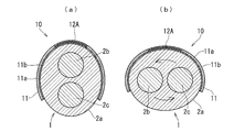
- FIGS. 3A and 3B are examples of mounting the mounting member 11 on the forearm 2a, and limit the positional relationship between the ribs 2b and ulna 2c and the mounting member 11 (first detection sensor 12A). It is not a thing.
- the third sheet 11f attached to both surfaces of the sensor body 12a of the first detection sensor 12A has a release layer on the surface opposite to the sensor body 12a.
- the sensor body 12a can be slid with respect to the base portion 11a and the adhesive portion 11b. Therefore, when the mounting member 11 is bent together with the first detection sensor 12A, the difference in curvature from the base portion 11a, the adhesive portion 11b, and the like is absorbed by sliding on the release layer of the third sheet 11f. Can do. Thereby, the mounting member 11 (the first detection sensor 12A) can be bent smoothly, and the rotation of the forearm 2a can be detected.
- the mounting member 11 has the support part 11c which does not produce wrinkles between the first detection sensor 12A and the adhesive part 11b, the support part 11c smoothes the partial unevenness on the surface of the forearm part 2a.
- the first detection sensor 12A can stably detect a change in the surface shape of the forearm 2a. More specifically, when the sensor main body 12a is directly attached to the adhesive portion 11b, the sensor main body 12a is deformed along the partial unevenness of the surface of the forearm portion 2a, so that the uneven portion becomes the entire detection signal. This may affect the output of a detection signal that is different from the original detection signal for the amount of deflection of the sensor body 12a. In contrast, by attaching the support portion 11c between the sensor main body 12a and the adhesive portion 11b, the sensor main body 12a can be bent without causing partial unevenness by the support portion 11c. The detection signal can be reliably output.
- the prosthetic hand mounting member 21 of the electric prosthesis 20 is then attached to the forearm 2a.
- the output part 13 of the human body detection apparatus 10 and the control apparatus 30 of the electric prosthesis 20 are electrically connected.
- the connection between the output unit 13 and the control unit 31 may be performed before the human body detection device 10 or the electric prosthesis 20 is mounted on the forearm 2a.
- a power switch (not shown) in the electric prosthesis 20 is turned on.
- the rotation angle of the forearm 2a is set to the center position (position between (a) and (b) in FIG. 3) of the rotation range.
- the control program is read from the storage part 32 and executed. This control program is initially executed in the “correction / hold mode” as the control mode.
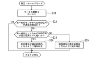
- step S31 the drive of the motor 28 is held, that is, locked so as not to move.
- step S32 it is determined whether or not the control signal from the first detection sensor 12A is within an appropriate range. If the control signal from first detection sensor 12A is within an appropriate range (YES in step S32), the process ends in the current state. On the other hand, if the control signal from first detection sensor 12A is not in the proper range (NO in step S32), it is determined whether or not the control signal from first detection sensor 12A is lower than the proper range (step S33). .
- step S33 When it is determined that the control signal from the first detection sensor 12A is lower than the appropriate range (YES in step S33), the control signal is increased and corrected (step S34) so that the control signal is within the appropriate range. ) To finish.
- step S34 the control signal from the first detection sensor 12A is not within the appropriate range in the previous step S32. Since it is determined as (NO), it is determined that the control signal from the first detection sensor 12A is higher than the appropriate range, and the control signal is decreased and corrected (step) so that the control signal is within the appropriate range. S35) is performed and the process ends.
- the control signal (the rotation angle of the forearm portion 2a) from the first detection sensor 12A at the time of starting (holding the drive of the motor 28 in step S31) will be described later. It can be automatically corrected as the origin signal (the origin of rotation of the forearm 2a) in the “operation mode”. Further, in the “correction / hold mode”, the drive of the motor 28 can be held by the process of step S31.
- mode change is performed to change the control mode to either “operation mode” or “correction / hold mode”.
- mode change the forearm portion 2a is moved so as to shake or vibrate without rotating the forearm portion 2a so that an acceleration equal to or higher than a threshold value described later acts on the portion where the mounting member 11 is attached. By doing. Since the second detection sensor 12B that detects acceleration according to the present embodiment can detect acceleration in three directions, the forearm 2a may be moved in any direction.
- “Mode change” is an interrupt routine.
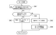
- mode change since the detection signal represented by a line having a portion where the value changes abruptly can be output from the second detection sensor 12B, the control mode is changed for the portion where the value changes rapidly. It is used as a control signal (switch signal) for this purpose. As shown in FIG. 8, this “mode change” stands by until the control signal from the second detection sensor 12B exceeds a preset threshold value (NO in step S41).
- step S42 When the control signal from the second detection sensor 12B exceeds the threshold value (YES in step S41), it is determined whether or not the current mode is the “operation mode” (step S42). Since the power switch of the electric prosthesis 20 is initially turned on, it is in “correction / hold mode”, so it is determined that the current mode is not “operation mode” (NO in step S42). To “operation mode” (step S43). Thereafter, the drive hold of the motor 28 is released (step S44), and the process ends.
- step S42 if it is determined that the current mode is the “operation mode” (YES in step S42), the operation mode is switched from the “operation mode” to the “correction / hold mode” (step S45), and the process ends.
- an acceleration equal to or higher than the threshold is applied to the portion of the mounting member 11 mounted on the forearm 2a, thereby changing from the “correction / hold mode” to the “operation mode” or “ The operation mode can be changed to the “correction / hold mode”.
- the motor 28 of the gripping device 25 is driven so that the pair of gripping portions 27 are moved. Open and close. Since the first detection sensor 12 ⁇ / b> A can output a control signal represented by a smooth line without a disordered portion whose value changes rapidly, the pair of gripping portions 27 are smoothly opened and closed via the motor 28. Can be made.
- the motor 28 is rotated in the direction in which the pair of gripping portions 27 opens when the outer rotation is performed from the center position (the rotation of the back of the hand toward the front of the body).
- the motor 28 is rotated in a direction in which the pair of gripping portions 27 are closed.
- the “correction / hold mode” is changed to the “operation mode” and the drive hold of the motor 28 is held. Canceled. Thereafter, by rotating the forearm 2a outwardly, the pair of grips 27 can be opened to release the “thing”.
- the human body detection device 10 of the present embodiment different movements are detected by mounting the mounting member 11 between the elbow joint 3 and the wrist joint (forearm 2a) as the joints of the human body.
- the first detection sensor 12A and the second detection sensor 12B are attached between the joints. And if the surface shape of the forearm part 2a which has mounted
- the detection sensor 12 corresponding to a specific movement is detected in the forearm 2a on which the mounting member 11 is mounted, and the control signal is output from the output unit 13 to the electric prosthesis 20 as a control target. Therefore, the other detection sensors 12 are not erroneously detected, and the malfunction of the electric prosthesis 20 due to the erroneous detection can be reduced.
- the first detection sensor 12A and the second detection sensor 12B detect the movement of the human body in the forearm portion 2a wearing the mounting member 11, unlike the conventional technique for detecting the surface myoelectric potential, If there is a muscle, it can be moved easily, and the intention (movement) of the user's operation can be reliably detected. Accordingly, an input operation can be easily performed on the electric prosthetic hand 20, and a training period necessary for learning the input operation can be shortened.
- the mounting member 11 is attached to the surface of the forearm portion 2a by the adhesive portion 11b, for example, compared to the case where the belt-shaped mounting member is wound around the human body and mounted on the surface of the forearm portion 2a.
- the mounting member 11 does not move. Therefore, it is possible to prevent displacement of the detection sensor 12 with respect to the surface of the forearm 2a, and to reliably detect the movement of the human body.
- the position shift of the detection sensor 12 can be prevented, erroneous detection due to the position shift can be suppressed, and the malfunction of the electric prosthesis 20 can be reduced.
- the attachment member 11 is attached by attaching the adhesive portion 11b to the surface of the forearm portion 2a, for example, the attachment member is used as a belt-like member and attached using a hook-and-loop fastener or a buckle. Compared to the case, the mounting member 11 can be attached to the surface of the forearm 2a with one hand.
- the mounting member 11 includes a plurality of sheets such as the first sheet 11d, the second sheet 11e, and the third sheet 11f between the first detection sensor 12A and the adhesive portion 11b, the adhesive portion It is possible to suppress the first detection sensor 12A and the base portion 11a from sticking strongly to 11b. Therefore, the adhesive portion 11b can be easily peeled off when the first detection sensor 12A fails or when the mounting member 11 is washed.
- the adhesion part 11b is affixed on a human body and is easy to get dirty, it is good also considering the adhesion part 11b as two layers (double).
- the present invention is not limited to this, and the muscle of the part where the mounting member 11 is mounted is shown. You may make it detect the shape change by expansion
- the detection signal from the detection sensor 12 is converted into a control signal by the conversion circuit 13b of the output unit 13 and output.
- the output signal may be output as a control signal as it is without being converted from the detection signal.
- the 1st detection sensor 12A which consists of a distortion sensor, and the 2nd detection sensor 12B which consists of an acceleration sensor were shown as a some detection sensor 12, it is not limited to this, A detection As the sensor 12, a pressure-sensitive sensor, a gyro sensor (gyroscope), a potentiometer, an optical sensor, a vibration sensor, or the like may be used.
- control signal from the first detection sensor 12A is corrected in the correction / hold mode.
- present invention is not limited to this, and the voltage for driving the motor 28 is determined. The voltage may be corrected.
- the human body detection device 10 is applied to the electric prosthesis 20
- the present invention is not limited thereto, and the electric prosthesis, the power assist suit, the wheelchair, the tool, the care device, the personal computer, You may apply to.
- the example in which the mounting member 11 of the human body detection device 10 is mounted on the forearm 2a has been shown.
- the present invention is not limited to this, and the shoulder joint and elbow joint are not limited to this. Between the wrist and hip joint, between the hip and knee joint, between the knee joint and ankle joint, between the foot joint and the foot joint, between the shoulder joint and the hip joint, the head side than the neck (cervical spine), It may be attached to the body.
Abstract
制御対象の誤動作を低減させることができると共に使用者が簡単に入力操作できる人体検知装置を提供する。 人体検知装置(10)に、可撓性を有したシート状のベース部(11a)、ベース部(11a)の一方の面に取付けられており人体表面に着脱可能に貼付けられるシート状の粘着部(11b)、及び粘着部(11b)とベース部(11a)との間に取付けられており人体表面に沿って曲がる平板状のサポート部(11c)を有しており、人体における関節間に装着される装着部材(11)と、装着部材(11)に取付けられており、人体における装着部材(11)が装着されている部位の動きを検知する第一検知センサ(12A)と、第一検知センサ(12A)による検知信号を、電動義手を制御するための制御信号に変換して出力する出力部と、を具備させる。
Description
本発明は、人体に装着することにより装着した部位の動きを検知して、義肢やアシスト装置等の制御対象を制御するための制御信号を出力する人体検知装置に関する。
電動義手のハンドを開閉させるためのモータ(制御対象)を制御するための制御信号として、電動義手が装着される人体の前腕部に取付けられ、筋肉を動かすために脳から送られる微弱な電気的な信号(表面筋電位)を検知して制御信号として出力する筋電センサが提案されている(特許文献1)。
しかしながら、特許文献1のような技術では、人体の表面筋電位を検知するようにしているため、使用者の意思どおりにハンドを動作させることが困難であった。詳述すると、一般の使用者では、表面筋電位を安定して発生させることが難しく、使用者が同じように操作した(表面筋電位を発生させた)つもりでも、筋電センサにより検知される値が異なることがあるため、電動義手のハンドによって物を掴むことができたり、掴むことができなかったりして、動作が不安定となる問題があった。そのため、表面筋電位を安定して発生させることができるように、長期に亘って訓練を行う必要があり、電動義手の操作の習熟に時間がかかってしまう問題があった。
また、訓練によって表面筋電位を安定して発生させることができるようになったとしても、例えば、ハンドによって物を掴ませた状態で、その物を移動させるために腕を動かす場合、腕を動かすことによって筋電センサで検知している部位で意図しない表面筋電位が発生してしまうことがあり、その意図しない表面筋電位が筋電センサによって検知されると、ハンドに掴ませた物を放してしまうような誤動作をする問題があった。
ところで、筋電センサとは別に、タッチ式のスイッチを設け、スイッチを操作することで使用状況に応じた動作モードで動作させることができるようにした電動義手が提案されている(特許文献2)。
しかしながら、特許文献2の技術では、電動義手を装着している腕とは反対側の腕でスイッチを操作する必要があるため、両腕を用いた作業を行う場合、反対側の腕でスイッチを操作することができない問題がある。そこで、スイッチを、例えば、人体の肩に取付けて顎や首筋等で操作できるようにしたり、足で操作できるようにしたりすることが考えられるが、使用者に無理な姿勢を強いることとなり、使用し辛くなる虞がある。
そこで、本発明は上記の実情に鑑み、制御対象の誤動作を低減させることができると共に使用者が簡単に入力操作できる人体検知装置の提供を課題とする。
上記の課題を解決するために、本発明に係る人体検知装置は、「可撓性を有したシート状のベース部、該ベース部の一方の面に取付けられており人体表面に着脱可能に貼付けられるシート状の粘着部、及び該粘着部と前記ベース部との間に取付けられており人体表面に沿って曲がる平板状のサポート部を有しており、人体における関節間に装着される装着部材と、該装着部材に取付けられており、人体における該装着部材が装着されている部位の動きを検知する検知センサと、該検知センサによる検知信号を、制御対象を制御するための制御信号に変換して出力する出力部とを具備している」ことを特徴とする。
ここで、可撓性を有したシート状の「ベース部」としては、「発泡樹脂シート」、「ゴムシート」、「シリコーン樹脂シート」、「織布」、「不織布」、を例示することができる。
また、「粘着部」としては、「親水性ゲルシート」、「疎水性ゲルシート」、「導電性ゲルシート」、等を例示することができる。また、「粘着部」の材質としては、「シリコーン樹脂」、「アクリル樹脂」、「ゴム」、「ウレタン樹脂」、等を例示することができる。
更に、「サポート部」としては、曲げた(曲がる)時に皺が生じないもの(厚さ)であれば良く、「ステンレス合金やアルミ合金等の金属板」、「合成樹脂板」、「厚紙」、等を例示することができる。
また、「関節間」としては、「肩関節とひじ関節の間」、「ひじ関節と手関節の間」、「手関節よりも手先側」、「股関節とひざ関節との間」、「ひざ関節と足関節との間」、「足関節よりも足先側」、「肩関節と股関節の間」、「首(頸椎)よりも頭側」、「首関節と股関節の間(胴体)」、を例示することができる。
また、「装着部材」としては、「可撓性を有したシート状のベース部と、ベース部の一方の面に接着されており人体表面に貼付けられる粘着部と、を有している装着部材」、「人体に巻き掛けられる帯状のベース部と、ベース部の一方の面と反対側の面とに取付けられており互いに係合可能な面ファスナーと、を有している装着部材」、「人体に巻き掛けられる帯状のベース部と、ベース部の一端に取付けらておりベース部の他端側を取付けるためのバックルと、を有している装着部材」、「人体の一部を挿入可能とされており伸縮性を有した筒状の装着部材」、を例示することができる。また、装着部材は、検知センサ毎に分離していても良い。
更に、「人体における装着部材が装着されている部位の動き」としては、「人体表面の形状(凹凸)変化」、「関節間を結んだ軸線に対して直角方向に加速度が作用する動き」、「関節間を結んだ軸線の延びている方向に加速度が作用する動き」、「関節間を結んだ軸線の周りを回動(回旋)する動き」、「人体表面の伸縮」、を例示することができる。
また、「検知センサ」としては、「歪センサ」、「加速度センサ」、「感圧センサ」、「ジャイロセンサ(ジャイロスコープ)」、「ポテンショメータ」、「人体表面に発光部から照射た光を受光部で受光して動きを検知する光学センサ」、「振動センサ」、を例示することができる。また、検知センサは、複数備えても良く、この場合には、異なる種類のセンサであっても良いし、同じ種類のセンサであっても良い。更に、装着部材における検知センサを取付ける部位については、「ベース部とサポート部との間」、「粘着部とサポート部との間」、「ベース部における粘着部とは反対側」、等を例示することができる。
また、「出力部」としては、「検知センサによる検知信号を増幅する増幅回路を有しているもの」、「検知センサによる検知信号からノイズを除去したり特定の周波数(動き)や閾値以上の検知信号等を取り出したりするフィルタ回路を有しているもの」、「検知センサによる検知信号が予め設定された閾値を超えたか否かを判定する判定回路を有しているもの」、「検知センサによる検知信号に対して演算処理を行う演算回路を有しているもの」、「検知センサを駆動させるためのセンサ駆動回路を有しているもの」、「検知センサによる検知信号をそのまま制御信号として出力するもの」、を例示することができる。また、「出力部」からは、複数の検知センサからの検知信号を夫々別々の制御信号として出力させるようしても良いし、複数の検知センサからの検知信号をまとめて一つの制御信号として出力させるようにしても良い。
更に、「制御対象」としては、「駆動源により駆動される義肢(電動義手、電動義足、等)」、「パワーアシストスーツ」、「車椅子」、「工具」、「介護装置」、「パーソナルコンピュータ」、を例示することができる。
ところで、人体における装着部材が装着されている部位の動きとして、人体表面の形状変化を検知する場合、人体表面の形状を変化させた時の人体表面、或いは、装着部材のベース部や粘着部に、皺等の部分的な凹凸が発生することがある。そして、人体表面の形状の変化により発生した凹凸を、検知センサが検知すると、人体表面における検知センサによる検知領域内の全体的(平均的)な形状変化とは異なる検知信号を出力してしまい、制御対象が誤動作する虞がある。
本構成によれば、検知センサが取付けられている装着部材を、粘着部によって人体の関節間における人体表面に貼付けて装着しているため、例えば、帯状の装着部材を人体に巻き付けて装着する場合と比較して、人体に対して装着部材が移動することはない。従って、人体に対する検知センサの位置ズレを防止することができ、人体における装着部材を装着した部位の動きを確実に検知させることができる。また、検知センサの位置ズレを防止することができるため、位置ズレによる誤検知を抑制することができ、制御対象の誤動作を低減させることができる。
また、粘着部を人体表面に貼付けることで装着部材を装着することができるため、例えば、装着部材を帯状の部材として、面ファスナーやバックルを用いて装着するようにした場合と比較して、片手でも装着部材を人体表面に貼付けて簡単に装着することができ、使い易くすることができる。
更に、装着部材のベース部と粘着部との間に人体表面に沿って曲がる平板状のサポート部を備えているため、人体表面の形状を変化させると、サポート部が人体表面の形状変化に応じて、部分的な皺等の凹凸を生じさせることなく滑らかに曲がる(形状が変化する)こととなる。そして、このサポート部の形状変化を検知センサにより検知させるようにすることで、人体表面、ベース部、及び粘着部、等において生じた皺等の部分的な凹凸を検知することはなく、人体表面の形状変化に応じた検知信号を確実に出力することができ、誤検知による制御対象の誤動作を低減させることができる。
なお、検知センサを複数の検知センサで構成し、複数の検知センサにより、人体における装着部材が装着されている部位において互いに異なる動きを夫々検知させるようにすることが望ましい。これにより、装着部材を介して複数の検知センサが取付けられている関節間において、使用者が或る動きを行うと、複数の検知センサのうち、或る動きに対応している検知センサのみが動きを検知し、その検知信号を、制御対象を制御するための制御信号に変換して出力する。一方、複数の検知センサのうち、或る動きに対応していない検知センサでは、或る動きを検知しないため、それら検知センサに係る制御信号は出力されない。従って、装着部材を装着している人体の関節間において、特定の動きに対応している検知センサのみがその動き検知して制御信号を出力するため、他の検知センサが誤検知することはなく、誤検知による制御対象の誤動作を低減させることができる。
また、上記のように検知センサを複数の検知センサで構成した場合、互いに異なる動きを検知する複数の検知センサが、誤検知することがないため、使用者が、装着部材を装着している関節間において異なる動き(入力操作)を行うことにより、互いに干渉することのない異なる複数の制御信号を制御対象へ出力することができる。従って、異なる複数の制御信号を出力することができるため、制御対象に対してより複雑な入力操作を行うことができる。換言すると、複雑な入力操作を必要する制御対象にも、本構成の人体検知装置を用いることができる。
更に、検知センサを複数の検知センサで構成した場合、人体における関節間に、複数の検知センサが取付けられている装着部材を装着することで、上記のように、異なる複数の制御信号を出力することができるため、特許文献2のような従来の技術と異なり、装着部材を装着していない反対側の腕等の部位を用いて別の制御信号を出力するスイッチを操作する必要がない。従って、装着部材を装着した当該関節間のみで制御対象に対して入力操作を行うことが可能となるため、人体における他の部位を自由に使用することができる。
また、本発明に係る人体検知装置は、上記の構成に加えて、「前記検知センサは、前記装着部材の前記ベース部と前記粘着部との間に取付けられており、前記装着部材が装着されている部位の人体表面の形状変化を検知する第一検知センサと、前記装着部材の前記ベース部に取付けられており、人体における前記装着部材が装着されている部位に作用する加速度又は角速度を検知する第二検知センサと、で構成されている」ことを特徴としても良い。
ここで、「人体表面の形状変化」としては、「骨の移動による表面の形状変化(具体的には、ひじ関節と手関節の間の前腕部や、ひざ関節と足関節の間の下腿部のように二本の骨が延びている関節間において、互いの骨が捩れるように移動させることによる表面の形状変化)」、「筋肉の伸長・収縮による表面の形状変化」、を例示することができる。
また、人体表面の形状変化を検知する「第一検知センサ」としては、「歪センサ」、「感圧センサ」、「人体表面に光を照射して動きを検知する光学センサ」、を例示することができる。
更に、「装着部材が装着されている部位に作用する加速度」としては、「互いに直交した三方向に作用する加速度」、「関節間を結んだ軸線に対して直交した方向に作用する加速度」、「関節間を結んだ軸線の延びた方向に作用する加速度」、「関節間を結んだ軸線の周りを回る方向へ作用する加速度」、を例示することができる。
また、加速度又は角速度を検知する「第二検知センサ」としては、「互いに直交した三方向に作用する加速度を検知する加速度センサ」、「一方向に作用する加速度のみを検知する加速度センサ」、「ジャイロセンサ」、「振動センサ」、を例示することができる。
装着部材を装着する関節間では、当該関節間にある筋肉を伸長・収縮させたり、当該関節間に亘って二本の骨が延びている場合はそれら二本の骨が捩れるように骨を移動させたりすることで、人体表面の形状を変化させることができる。また、当該関節間では、当該関節間において胴体に近い側の関節よりも胴体側の筋肉(例えば、上腕二頭筋、上腕三頭筋、三角筋、大腿二頭筋、大腿四頭筋、等)を伸長・収縮させることで、胴体に近い側の関節を中心に当該関節間を回動させたり、当該関節間における胴体に近い側の関節を含む胴体に近い側の複数の関節を夫々中心に適宜回動させたりすることで、当該関節間に加速度を作用させることができる。
そして、当該関節間において、人体表面の形状を変化させた場合、表面の形状変化だけでは十分な加速度を当該関節間に作用させることは難しい。一方、当該関節間において加速度を作用させた場合、当該関節間における人体表面の形状を変化させることなく加速度を作用させることが可能である。
本構成によれば、装着部材を装着している関節間の表面形状を変化させると、第一検知センサのみがその動きを検知し、当該関節間に加速度を作用させると、第二検知センサのみがその動きを検知することとなり、第一検知センサと第二検知センサとによって、当該関節間における互いに異なる動きを確実に検知することができる。従って、装着部材を装着している人体の関節間において、特定の動きに対応している第一検知センサ又は第二検知センサのみがその動き検知して制御信号を出力するため、残りの検知センサ(第二検知センサ又は第一検知センサ)が誤検知することはない。これにより、誤検知による制御対象の誤動作を低減させることができ、上述した作用効果を確実に奏することが可能な人体検知装置を具現化することができる。
更に、本発明に係る人体検知装置は、上記の構成に加えて、「前記第一検知センサは、制御対象を動作させるための制御信号を前記出力部から出力させるためのものであり、且つ、前記第二検知センサは、前記第一検知センサからの制御信号により制御される制御対象の制御モードを変更するための制御信号を前記出力部から出力させるためのものである」ことを特徴としても良い。
ここで、「制御モード」としては、「第一検知センサから検知信号により制御対象を動作させる動作モード」、「第一検知センサからの検知信号を受付けず、制御対象の動作を停止させるホールドモード」、「制御対象の動作に対して、第一検知センサからの検知信号に対して任意の値を原点とするように補正する補正モード」、「ホールドモードと補正モードとを合わせた補正・ホールドモード」、等を例示することができる。
本構成によれば、制御対象を動作させるための制御信号の出力に用いられる第一検知センサは、人体表面の形状変化を検知していることから、値が急激に変化する乱れた部位の無い滑らかな線で表される検知信号を出力させることができるため、この検知信号を制御信号に用いることで制御対象を滑らかに動作させることができる。一方、制御対象の制御モードの変更に用いられる第二検知センサは、加速度又は角速度を検知していることから、値が急激に変化する部位を有する線で表される検知信号を出力させることができるため、急激に変化している部位を利用することで制御モードを変更するための制御信号(スイッチ信号)として好適に用いることができ、制御対象の制御モードを確実に変更させることができる。従って、上述した作用効果を確実に奏することが可能な人体検知装置を具現化することができる。
このように、本発明によれば、制御対象の誤動作を低減させることができると共に使用者が簡単に入力操作できる人体検知装置を提供することができる。
本発明の一実施形態である人体検知装置10について、図1乃至図8を参照して詳細に説明する。本実施形態では、人体検知装置10を、制御対象としての電動義手20に適用した例について説明する。本実施形態の人体検知装置10は、人体1における関節間2に装着される装着部材11と、装着部材11に取付けられており、人体における装着部材11が装着されている部位において互いに異なる動きを夫々検知する複数の検知センサ12と、複数の検知センサ12による検知信号を、電動義手20を制御するための制御信号に変換して出力する出力部13と、を備えている。
装着部材11は、図1に示すように、人体1の関節間2として、ひじ関節3と手関節の間(前腕部2a)に装着されるものである。装着部材11は、長方形のシート状(パッド状)に形成されている。この装着部材11は、図2及び図3に示すように、可撓性を有したシート状のベース部11aと、ベース部11aの一方の面に取付けられており人体表面に着脱可能に貼付けられるシート状の粘着部11bと、を有している。ベース部11aと粘着部11bは、同じ大きさに形成されており、粘着部11bの粘着力によって互いに取付けられている。ベース部11aは、発泡樹脂シートによって形成されている。また、粘着部11bは、親水性高分子からなる親水性ゲルシートによって形成されている。
また、装着部材11は、図2に示すように、ベース部11aと粘着部11bとの間に取付けられ湾曲状に曲がる平板状のサポート部11cと、サポート部11cのベース部11a側の面に取付けられる第一シート11dと、第一シート11dのベース部11a側の面に取付けられる第二シート11eと、第二シート11eのベース部11a側の面に取付けられる一対の第三シート11fと、を有している。サポート部11cは、ベース部11a及び粘着部11bよりも大きさが小さい。このサポート部11cは、ステンレス合金やアルミ合金等の金属板、合成樹脂板、厚紙、等により、曲げた時に皺が生じない厚さに形成されている。
第一シート11d、及び、第二シート11eは、サポート部11cと同じ大きさで、合成樹脂により形成されている。これら、サポート部11c、第一シート11d、及び、第二シート11eは、両面のうちの少なくともベース部11aを向いた面に、粘着層を有している。また、一対の第三シート11fは、サポート部11c等よりも大きさが小さい。これら第三シート11fは、紙、又は、合成樹脂によって形成されており、互いに対向している面に粘着層を有していると共に、それとは反対の面に接着力を弱める離型層を有している。
複数の検知センサ12は、人体表面の形状変化を検知する第一検知センサ12Aと、人体における装着部材11が装着されている部位に作用する加速度を検知する第二検知センサ12Bと、で構成されている。
第一検知センサ12Aは、撓み量によって電気抵抗値が変化する歪センサである。この第一検知センサ12Aは、図2に示すように、長方形で平板状のセンサ本体12aと、センサ本体12aから外部へ延び出しているリード線12bと、リード線12bを被覆している被覆管12cと、センサ本体12aと被覆管12cとの間で露出しているリード線12bを覆う被覆部12dと、を有している。被覆部12dは、熱可塑性樹脂により構成されており、リード線12bが断線しないように保護している。
この第一検知センサ12Aは、図2に示すように、装着部材11において、ベース部11aと粘着部11bとの間に取付けられている。詳しくは、第一検知センサ12Aは、センサ本体12aの長手方向を、装着部材11の長手方向と同じ方向へ向けて、センサ本体12aと被覆部12dとが一対の第三シート11fの間に取付けられている。また、第一検知センサ12Aは、被覆管12cに被覆されたリード線12bが、装着部材11の長辺から外部に延び出すように取付けられている(図1を参照)。
また、第二検知センサ12Bは、互いに直交した三方向に作用する加速度を検知する。この第二検知センサ12Bは、図1等に示すように、装着部材11のベース部11aにおいて、粘着部11bとは反対側の面に取付けられている。第二検知センサ12Bは、被覆管に被覆されたリード線12eを有しており、このリード線12eが、第一検知センサ12Aの被覆管12cと一緒に装着部材11から外部の出力部13まで延び出している。
出力部13は、図4に示すように、検知センサ12を駆動させるための電力を供給するセンサ駆動回路13aと、検知センサ12からの検知信号を制御信号に変換する変換回路13bと、を備えている。変換回路13bは、検知センサ12からの検知信号を増幅する増幅回路13cと、検知信号に含まれているノイズを除去したり特定の周波数のみを通したりするフィルタ回路13dと、検知信号に対して演算処理を行う演算回路13eと、を備えている。この出力部13は、図示は省略するが、電動義手20に取付けられている。
出力部13の変換回路13bにおいて、第一検知センサ12Aからの検知信号に対しては、図5に示すように、増幅回路13cにて増幅処理(ステップS11)を行った後に、フィルタ回路13dにてローパスフィルタ処理(ステップS12)を行うことで、制御信号に変換し、演算回路13eを通さずに出力する。
一方、第二検知センサ12Bからの検知信号に対しては、図6に示すように、まず、増幅回路13cにて増幅処理(ステップS21)を行った後に、フィルタ回路13dにてバンドパスフィルタ処理(ステップS22)を行う。続いて、演算回路13eにおいて、三方向の各方向に対して夫々2乗平均処理(ステップS23)を行い、それらの値に対して時間微分処理(ステップS24)を行って躍度(加速度の時間微分)を求める。その後、各方向の躍度に対して絶対値処理(ステップS25)を行った後に、それらを合算することで、制御信号に変換して出力する。このように、本実施形態の変換回路13bは、第一検知センサ12Aと第二検知センサ12Bとでは異なる回路を通って制御信号に変換する。
次に、本実施形態の人体検知装置10を適用した電動義手20について説明する。電動義手20は、図1に示すように、使用者の人体1の前腕部2aを覆う義手取付部材21と、義手取付部材21の前端に取付けられている把持装置25と、人体検知装置10からの制御信号に基づいて把持装置25を制御する制御装置30(図4を参照)と、を備えている。
義手取付部材21は、前腕部2aの外周の半分以上を覆うように筒状又は断面がC字状に形成されている。義手取付部材21は、前腕部2aに取付けた状態で、前腕部2aよりも前端(失われた部位)側へ突出する長さに形成されている。
この義手取付部材21内に前腕部2aを挿入することにより、前腕部2aに義手取付部材21を取付けることができる。また、義手取付部材21を前腕部2aに取付けた状態では、前腕部2aの前端側を自由に回旋させることができる。
把持装置25は、義手取付部材21の前端に取付けられる本体部26と、本体部26によって開閉可能に取付けられている一対の把持部27と、一対の把持部27を開閉駆動し本体部26内に取付けられているモータ28(図4を参照)と、を備えている。モータ28は、回転位置を出力することができるサーボモータである。
制御装置30は、制御プログラムを実行させて演算を行うCPUを備えている制御部31と、制御部31で実行される制御プログラムや設定値、演算の際の一時的な数値、等を記憶するための記憶部32と、制御部31からの駆動信号に基いてモータ28を駆動させるモータ駆動部33と、を備えている。また、図示は省略するが、制御装置30は、制御部31や、モータ駆動部33等に電力を供給するための電源部を備えている。
本実施形態の制御装置30は、マイクロコンピュータ(マイコン)である。制御装置30の制御部31には、人体検知装置10からの制御信号と、モータ28からの回転位置信号が入力される。人体検知装置10からの制御信号は、第一検知センサ12Aに係る制御信号と、第二検知センサ12Bに係る制御信号とが、夫々別々に制御部31に入力される。また、制御部31からは、モータ駆動部33へモータ28の駆動信号が出力される。この制御装置30は、本体部26または、使用者の身体や着衣に取付けられる。
続いて、本実施形態の人体検知装置10の使用方法について説明する。人体1の関節間2としての前腕部2aの前端付近に、人体検知装置10の装着部材11を装着する。具体的には、装着部材11の粘着部11bを、前腕部2aに対向するように向けると共に、その長手方向を前腕部2aの軸線周りの方向へ向ける。そして、装着部材11を、前腕部2aに巻き付けるように、前腕部2aに粘着部11bを接触させる。これにより、粘着部11bの粘着力によって、検知センサ12と一緒に装着部材11が前腕部2aに取付けられる。
前腕部2aに装着部材11を取付けた状態では、図3(a)、(b)に示すように、橈骨2bと尺骨2cとが互いに捩れるように前腕部2aを回旋させると、橈骨2bと尺骨2cが並んでいる向きに応じて、前腕部2aの表面形状(曲率)が変化する。これにより、前腕部2aの表面に貼付けられ(装着され)ている第一検知センサ12Aの曲率も変化するため、第一検知センサ12Aによって前腕部2aの回旋角度(橈骨2bと尺骨2cとの捩れ角度)に応じた制御信号を出力することができる。なお、図3(a)、(b)では、人体検知装置10において、便宜上、ベース部11a、粘着部11b、及び第一検知センサ12Aのみを記載している。また、図3(a)、(b)は、前腕部2aに対する装着部材11の装着の一例であり、橈骨2b及び尺骨2cと装着部材11(第一検知センサ12A)との位置関係を限定するものではない。
ところで、第一検知センサ12Aのセンサ本体12aの両面に取付けられている第三シート11fにおいて、センサ本体12aとは反対側の面に離型層を有しているため、この離型層を境にして、センサ本体12aをベース部11aや粘着部11bに対して滑らせることができる。従って、第一検知センサ12Aと一緒に装着部材11を曲げた時に、第三シート11fの離型層を境に滑ることで、ベース部11aや粘着部11b等との曲率の違いを吸収することができる。これにより、装着部材11(第一検知センサ12A)をスムーズに曲げることができ、前腕部2aの回旋を検知することができる。
また、装着部材11では、第一検知センサ12Aと粘着部11bの間に、皺が生じないサポート部11cを有しているため、サポート部11cによって前腕部2aの表面の部分的な凹凸を平滑化させることができ、第一検知センサ12Aにより前腕部2aの表面形状の変化を安定して検知させることができる。詳述すると、センサ本体12aを粘着部11bに直接取付けた場合、センサ本体12aが前腕部2aの表面の部分的な凹凸に沿って変形してしまうため、その凹凸の部分が検知信号の全体に影響を与えてしまい、センサ本体12aの撓み量に対する本来の検知信号とは異なった検知信号を出力することがある。これに対して、センサ本体12aと粘着部11bの間にサポート部11cを取付けることで、サポート部11cによって部分的な凹凸を生じさせることなくセンサ本体12aを撓ませることができ、撓み量に対する本来の検知信号を確実に出力させることができる。
このように、前腕部2aに装着部材11を装着したら、続いて、前腕部2aに電動義手20の義手取付部材21を取付ける。そして、人体検知装置10の出力部13と、電動義手20の制御装置30とを電気的に接続する。なお、出力部13と制御部31との接続は、人体検知装置10や電動義手20を前腕部2aに装着する前に行っても良い。
人体検知装置10と電動義手20の装着が完了したら、電動義手20における図示しない電源スイッチをONにする。この際に、前腕部2aの回旋角度を、回旋範囲の中央の位置(図3の(a)と(b)との間の位置)としておく。本実施形態では、電動義手20の電源を入れると、人体検知装置10にも電源が供給される。そして、電動義手20の制御部31では、記憶部32から制御プログラムを読み出して実行する。この制御プログラムは、実行当初は制御モードとして「補正・ホールドモード」が実行される。
「補正・ホールドモード」は、図7に示すように、まず初めに、モータ28の駆動をホールド、つまり、動かないようにロックする(ステップS31)。続いて、第一検知センサ12Aからの制御信号が適正範囲内か否かが判定される(ステップS32)。そして、第一検知センサ12Aからの制御信号が適正範囲であれば(ステップS32においてYES)、現状のままの状態で終了する。一方、第一検知センサ12Aからの制御信号が適正範囲でなければ(ステップS32においてNO)、第一検知センサ12Aからの制御信号が適正範囲よりも低いか否かが判定される(ステップS33)。
そして、第一検知センサ12Aからの制御信号が適正範囲よりも低いと判定される(ステップS33においてYES)と、制御信号が適正範囲内となるように、制御信号に対して増加補正(ステップS34)を行って終了する。一方、第一検知センサ12Aからの制御信号が適正範囲よりも低くないと判定された(ステップS33においてNO)場合、先のステップS32において第一検知センサ12Aからの制御信号が適正範囲内ではない(NO)と判定されていることから、第一検知センサ12Aからの制御信号が適正範囲よりも高いと判断し、制御信号が適正範囲内となるように、制御信号に対して減少補正(ステップS35)を行って終了する。
このように、「補正・ホールドモード」では、開始(ステップS31においてモータ28の駆動をホールド)した時点での、第一検知センサ12Aからの制御信号(前腕部2aの回旋角度)を、後述する「動作モード」における原点信号(前腕部2aの回旋原点)として、自動的に補正することができる。また、「補正・ホールドモード」では、ステップS31の処理によって、モータ28の駆動をホールドすることができる。
「補正・ホールドモード」によって、第一検知センサ12Aからの制御信号に対する補正が完了したら、制御モードを「動作モード」又は「補正・ホールドモード」の何れかに変更する「モード変更」を行う。「モード変更」は、装着部材11が装着されている部位で後述する閾値以上の加速度が作用するように、前腕部2aを回旋させずに、前腕部2aを振ったり振動させたりするように動かすことにより行う。本実施形態の加速度を検知する第二検知センサ12Bは、三方向の加速度を検知することができるため、前腕部2aを何れの方向へ動かしても良い。また、「モード変更」は、割込みルーチンである。「モード変更」では、第二検知センサ12Bから、値が急激に変化する部位を有する線で表される検知信号を出力することができるため、急激に変化している部位を、制御モードを変更するための制御信号(スイッチ信号)として用いている。この「モード変更」は、図8に示すように、第二検知センサ12Bからの制御信号が、予め設定されている閾値を超えるまで待機している(ステップS41においてNO)。
そして、第二検知センサ12Bからの制御信号が閾値を超える(ステップS41においてYES)と、現在のモードが「動作モード」であるか否かが判定される(ステップS42)。電動義手20の電源スイッチをONにした当初は、「補正・ホールドモード」となっているため、現在のモードが「動作モード」ではないと判定され(ステップS42においてNO)、「補正・ホールドモード」から「動作モード」に切替える(ステップS43)。その後、モータ28の駆動のホールドを解除して(ステップS44)終了する。
一方、現在のモードが「動作モード」であると判定された(ステップS42においてYES)場合は、「動作モード」から「補正・ホールドモード」に切替えて(ステップS45)終了する。
このように、「モード変更」では、前腕部2aに装着されている装着部材11の部位に閾値以上の加速度を作用させることにより、「補正・ホールドモード」から「動作モード」、或は、「動作モード」から「補正・ホールドモード」、に変更させることができる。
「動作モード」では、前腕部2aの表面形状(回旋角度)の変化を検知する第一検知センサ12Aからの制御信号に基づいて、把持装置25のモータ28を駆動させて一対の把持部27を開閉動作させる。第一検知センサ12Aは、値が急激に変化する乱れた部位の無い滑らかな線で表される制御信号を出力させることができるため、モータ28を介して一対の把持部27を滑らかに開閉動作させることができる。この「動作モード」としては、例えば、前腕部2aの回旋範囲内において、中央の位置から外回旋(手の甲が体の前方へ向かう回旋)させると一対の把持部27が開く方向にモータ28を回転させ、中央の位置から内回旋(手の甲が体の後方へ向かう回旋)させると一対の把持部27が閉じる方向にモータ28を回転させる。
この「動作モード」において、前腕部2aを内回旋させて、一対の把持部27により「物」を把持させた状態で、前腕部2aに閾値以上の加速度を作用させると、「モード変更」により「動作モード」から「補正・ホールドモード」に変更される。「補正・ホールドモード」に変更されると、モータ28の駆動がホールドされ、前腕部2aを回旋させても、一対の把持部27は動くことはなく、「物」を把持した状態で維持される。これにより、前腕部2aやその他の身体等を使って、一対の把持部27に把持させた「物」を自由に移動させることができる。把持させた「物」を放す場合は、もう一度、前腕部2aに閾値以上の加速度を作用させると、「補正・ホールドモード」から「動作モード」に変更されると共に、モータ28の駆動のホールドが解除される。その後、前腕部2aを外回旋させることにより、一対の把持部27を開かせて「物」を放すことができる。
このように、本実施形態の人体検知装置10では、人体の関節間としてのひじ肘関節3と手関節の間(前腕部2a)に装着部材11を装着することで、互いに異なる動きを検知する第一検知センサ12Aと第二検知センサ12Bを、当該関節間に取付けている。そして、装着部材11を装着している前腕部2aの表面形状を変化させると、第一検知センサ12Aのみがその動きを検知し、前腕部2aに加速度を作用させると、第二検知センサ12Bのみがその動きを検知することとなり、第一検知センサ12Aと第二検知センサ12Bとによって、前腕部2aにおける互いに異なる動きを確実に検知することができる。従って、装着部材11を装着している前腕部2aにおいて、特定の動きに対応している検知センサ12のみがその動きを検知して出力部13から制御対象としての電動義手20へ制御信号を出力するため、他の検知センサ12が誤検知することはなく、誤検知による電動義手20の誤動作を低減させることができる。
また、前腕部2aに、第一検知センサ12Aと第二検知センサ12Bとが取付けられている装着部材11を装着することで、異なる二つの制御信号を出力することができるため、従来の技術とは異なり、装着部材11を装着していない反対側の腕等の部位を用いて別の制御信号を出力するスイッチを操作する必要がない。従って、装着部材11を装着した前腕部2aのみで電動義手20に対して入力操作を行うことができるため、人体における他の部位を自由に使用することができる。
また、第一検知センサ12A及び第二検知センサ12Bによって、装着部材11を装着している前腕部2aにおける人体の動きを検知しているため、表面筋電位を検知する従来の技術とは異なり、筋肉があれば容易に動かすことができ、使用者の操作に対する意思(動き)を確実に検知することができる。従って、電動義手20に対して簡単に入力操作を行うことができ、入力操作の習熟に必要な訓練期間を短縮することができる。
更に、装着部材11を、粘着部11bによって前腕部2aの表面に貼付けて装着しているため、例えば、帯状の装着部材を人体に巻き付けて装着する場合と比較して、前腕部2aの表面に対して装着部材11が移動することはない。従って、前腕部2aの表面に対する検知センサ12の位置ズレを防止することができ、人体の動きを確実に検知させることができる。また、検知センサ12の位置ズレを防止することができるため、位置ズレによる誤検知を抑制することができ、電動義手20の誤動作を低減させることができる。
また、粘着部11bを前腕部2aの表面に貼付けることで装着部材11を装着するようにしているため、例えば、装着部材を帯状の部材として、面ファスナーやバックルを用いて装着するようにした場合と比較して、片手でも装着部材11を前腕部2aの表面に貼付けることができる。
更に、装着部材11では、第一検知センサ12Aと粘着部11bとの間に、第一シート11d、第二シート11e、及び第三シート11f等の複数のシートを有しているため、粘着部11bに対して第一検知センサ12Aやベース部11aが強力に貼付くのを抑制することができる。従って、第一検知センサ12Aが故障した時や、装着部材11を洗浄する時に、粘着部11bを容易に剥がすことができる。なお、粘着部11bは人体に貼付けられることから汚れ易いため、粘着部11bを二層(二重)としても良い。
以上、本発明について好適な実施形態を挙げて説明したが、本発明は上記の実施形態に限定されるものではなく、以下に示すように、本発明の要旨を逸脱しない範囲において、種々の改良及び設計の変更が可能である。
例えば、上記の実施形態では、前腕部2aの回旋による形状変化を第一検知センサ12Aにより検知させる例を示したが、これに限定するものではなく、装着部材11が装着された部位の筋肉の伸長・収縮による形状変化を検知させるようにしても良い。
また、上記の実施形態では、検知センサ12からの検知信号を、出力部13の変換回路13bによって制御信号に変換して出力する例を示したが、これに限定するものではなく、検知センサ12からの検知信号を変換せずにそのままの状態で制御信号として出力させる出力部としても良い。
また、上記の実施形態では、複数の検知センサ12として、歪センサからなる第一検知センサ12Aと、加速度センサからなる第二検知センサ12Bとを示したが、これに限定するものではなく、検知センサ12として、感圧センサ、ジャイロセンサ(ジャイロスコープ)、ポテンショメータ、光学センサ、振動センサ、等を用いても良い。
更に、上記の実施形態では、補正・ホールドモードにおいて、第一検知センサ12Aからの制御信号を補正する例を示したが、これに限定するものではなく、モータ28を駆動する電圧を判定して、その電圧を補正するようにしても良い。
また、上記の実施形態では、人体検知装置10を電動義手20に適用した例を示したが、これに限定するものではなく、電動義足、パワーアシストスーツ、車椅子、工具、介護装置、パーソナルコンピュータ、等に適用しても良い。また、上記の実施形態では、人体検知装置10の装着部材11を、前腕部2aに装着する例を示したが、これに限定するものではなく、人体の関節間として、肩関節とひじ関節の間、手関節よりも手先側、股関節とひざ関節との間、ひざ関節と足関節との間、足関節よりも足先側、肩関節と股関節の間、首(頸椎)よりも頭側、胴体、等に装着しても良い。
Claims (3)
- 可撓性を有したシート状のベース部、該ベース部の一方の面に取付けられており人体表面に着脱可能に貼付けられるシート状の粘着部、及び該粘着部と前記ベース部との間に取付けられており人体表面に沿って曲がる平板状のサポート部を有しており、人体における関節間に装着される装着部材と、
該装着部材に取付けられており、人体における該装着部材が装着されている部位の動きを検知する検知センサと、
該検知センサによる検知信号を、制御対象を制御するための制御信号に変換して出力する出力部と
を具備していることを特徴とする人体検知装置。 - 前記検知センサは、
前記装着部材の前記ベース部と前記粘着部との間に取付けられており、前記装着部材が装着されている部位の人体表面の形状変化を検知する第一検知センサと、
前記装着部材の前記ベース部に取付けられており、人体における前記装着部材が装着されている部位に作用する加速度又は角速度を検知する第二検知センサと、
で構成されていることを特徴とする請求項1に記載の人体検知装置。 - 前記第一検知センサは、制御対象を動作させるための制御信号を前記出力部から出力させるためのものであり、且つ、
前記第二検知センサは、前記第一検知センサからの制御信号により制御される制御対象の制御モードを変更するための制御信号を前記出力部から出力させるためのものであることを特徴とする請求項2に記載の人体検知装置。
Applications Claiming Priority (2)
| Application Number | Priority Date | Filing Date | Title |
|---|---|---|---|
| JP2013-252624 | 2013-12-06 | ||
| JP2013252624A JP6084153B2 (ja) | 2013-12-06 | 2013-12-06 | 人体検知装置 |
Publications (1)
| Publication Number | Publication Date |
|---|---|
| WO2015083534A1 true WO2015083534A1 (ja) | 2015-06-11 |
Family
ID=53273301
Family Applications (1)
| Application Number | Title | Priority Date | Filing Date |
|---|---|---|---|
| PCT/JP2014/080420 WO2015083534A1 (ja) | 2013-12-06 | 2014-11-18 | 人体検知装置 |
Country Status (2)
| Country | Link |
|---|---|
| JP (1) | JP6084153B2 (ja) |
| WO (1) | WO2015083534A1 (ja) |
Families Citing this family (2)
| Publication number | Priority date | Publication date | Assignee | Title |
|---|---|---|---|---|
| JP6251302B2 (ja) * | 2016-01-27 | 2017-12-20 | H2L株式会社 | 電気刺激装置 |
| KR102371796B1 (ko) * | 2020-04-20 | 2022-03-11 | 한국과학기술연구원 | 변형 가능한 소재의 소켓을 구비한 지능형 의지장치 |
Citations (5)
| Publication number | Priority date | Publication date | Assignee | Title |
|---|---|---|---|---|
| JPH0412201A (ja) * | 1990-05-01 | 1992-01-16 | Komatsu Ltd | 関節の曲げ角検出センサ |
| JPH11113866A (ja) * | 1997-10-13 | 1999-04-27 | Nabco Ltd | 筋電センサ |
| WO2002099614A1 (en) * | 2001-06-01 | 2002-12-12 | Sony Corporation | User input apparatus |
| JP2005352739A (ja) * | 2004-06-10 | 2005-12-22 | Nec Corp | 携帯端末装置、入力システム、情報入力方法 |
| JP2006113777A (ja) * | 2004-10-14 | 2006-04-27 | Citizen Watch Co Ltd | 情報入力装置 |
-
2013
- 2013-12-06 JP JP2013252624A patent/JP6084153B2/ja not_active Expired - Fee Related
-
2014
- 2014-11-18 WO PCT/JP2014/080420 patent/WO2015083534A1/ja active Application Filing
Patent Citations (5)
| Publication number | Priority date | Publication date | Assignee | Title |
|---|---|---|---|---|
| JPH0412201A (ja) * | 1990-05-01 | 1992-01-16 | Komatsu Ltd | 関節の曲げ角検出センサ |
| JPH11113866A (ja) * | 1997-10-13 | 1999-04-27 | Nabco Ltd | 筋電センサ |
| WO2002099614A1 (en) * | 2001-06-01 | 2002-12-12 | Sony Corporation | User input apparatus |
| JP2005352739A (ja) * | 2004-06-10 | 2005-12-22 | Nec Corp | 携帯端末装置、入力システム、情報入力方法 |
| JP2006113777A (ja) * | 2004-10-14 | 2006-04-27 | Citizen Watch Co Ltd | 情報入力装置 |
Also Published As
| Publication number | Publication date |
|---|---|
| JP6084153B2 (ja) | 2017-02-22 |
| JP2015107281A (ja) | 2015-06-11 |
Similar Documents
| Publication | Publication Date | Title |
|---|---|---|
| JP2020518295A5 (ja) | ||
| JP5986629B2 (ja) | 胴体支持外骨格装置及びその使用方法 | |
| JP4573798B2 (ja) | 腰部支援装置 | |
| JP6279143B2 (ja) | 関節運動アシスト装置及び当該関節運動アシスト装置の装着方法 | |
| WO2013036925A2 (en) | Isolated orthosis for thumb actuation | |
| KR20170021108A (ko) | 운동 보조 장치 및 그 제어 방법 | |
| EP3270862A1 (en) | A modular universal joint with harmonised control method for an assistive exoskeleton | |
| US10993869B2 (en) | Finger motion aid and rehabilitation hand having same | |
| CN104398322B (zh) | 一种外骨骼机器人机械脊柱结构 | |
| JP2019513085A (ja) | 使用者の把持力を向上する装置 | |
| US11672721B2 (en) | Motion assisting apparatus | |
| Bos et al. | A case study with SymbiHand: an sEMG-controlled electrohydraulic hand orthosis for individuals with Duchenne muscular dystrophy | |
| Burns et al. | Towards a wearable hand exoskeleton with embedded synergies | |
| Lagoda et al. | Human-robot interfaces in exoskeletons for gait training after stroke: State of the art and challenges | |
| WO2019203732A1 (en) | Wearable hand assistive device and system | |
| CN112912040A (zh) | 手部辅助矫正器 | |
| JP2021501645A (ja) | 手外骨格装置 | |
| JP6372912B2 (ja) | リハビリテーション補助装置 | |
| WO2015083534A1 (ja) | 人体検知装置 | |
| Lin et al. | NTUH-II robot arm with dynamic torque gain adjustment method for frozen shoulder rehabilitation | |
| JP6479376B2 (ja) | 可動義手 | |
| US20230075880A1 (en) | Motion assist device | |
| US20230166391A1 (en) | Intelligent hand exoskeleton with grasping assistance | |
| KR102207991B1 (ko) | 시트형 근력 보조 슈트 | |
| JP6299008B2 (ja) | パワーアシストロボット |
Legal Events
| Date | Code | Title | Description |
|---|---|---|---|
| 121 | Ep: the epo has been informed by wipo that ep was designated in this application |
Ref document number: 14868386 Country of ref document: EP Kind code of ref document: A1 |
|
| NENP | Non-entry into the national phase |
Ref country code: DE |
|
| 122 | Ep: pct application non-entry in european phase |
Ref document number: 14868386 Country of ref document: EP Kind code of ref document: A1 |