WO2015080096A1 - Display device and display method - Google Patents
Display device and display method Download PDFInfo
- Publication number
- WO2015080096A1 WO2015080096A1 PCT/JP2014/081091 JP2014081091W WO2015080096A1 WO 2015080096 A1 WO2015080096 A1 WO 2015080096A1 JP 2014081091 W JP2014081091 W JP 2014081091W WO 2015080096 A1 WO2015080096 A1 WO 2015080096A1
- Authority
- WO
- WIPO (PCT)
- Prior art keywords
- display
- video signal
- display unit
- display device
- unit
- Prior art date
Links
Images


Classifications
-
- H—ELECTRICITY
- H04—ELECTRIC COMMUNICATION TECHNIQUE
- H04N—PICTORIAL COMMUNICATION, e.g. TELEVISION
- H04N13/00—Stereoscopic video systems; Multi-view video systems; Details thereof
- H04N13/30—Image reproducers
- H04N13/332—Displays for viewing with the aid of special glasses or head-mounted displays [HMD]
- H04N13/341—Displays for viewing with the aid of special glasses or head-mounted displays [HMD] using temporal multiplexing
-
- H—ELECTRICITY
- H04—ELECTRIC COMMUNICATION TECHNIQUE
- H04N—PICTORIAL COMMUNICATION, e.g. TELEVISION
- H04N13/00—Stereoscopic video systems; Multi-view video systems; Details thereof
- H04N13/30—Image reproducers
- H04N13/302—Image reproducers for viewing without the aid of special glasses, i.e. using autostereoscopic displays
- H04N13/305—Image reproducers for viewing without the aid of special glasses, i.e. using autostereoscopic displays using lenticular lenses, e.g. arrangements of cylindrical lenses
-
- H—ELECTRICITY
- H04—ELECTRIC COMMUNICATION TECHNIQUE
- H04N—PICTORIAL COMMUNICATION, e.g. TELEVISION
- H04N13/00—Stereoscopic video systems; Multi-view video systems; Details thereof
- H04N13/30—Image reproducers
- H04N13/302—Image reproducers for viewing without the aid of special glasses, i.e. using autostereoscopic displays
- H04N13/31—Image reproducers for viewing without the aid of special glasses, i.e. using autostereoscopic displays using parallax barriers
-
- H—ELECTRICITY
- H04—ELECTRIC COMMUNICATION TECHNIQUE
- H04N—PICTORIAL COMMUNICATION, e.g. TELEVISION
- H04N13/00—Stereoscopic video systems; Multi-view video systems; Details thereof
- H04N13/30—Image reproducers
- H04N13/324—Colour aspects
Definitions
- the present invention relates to a display device for displaying an image and a display method used in such a display device.
- see-through displays In recent years, so-called see-through displays have been developed in which the display section is made of a transparent material. Unlike a normal display device, a display device having such a transmissive display unit can display characters and images superimposed on an actual landscape. Such a display device is expected to be used for various purposes such as AR (Augmented Reality).
- AR Augmented Reality
- Such a transmissive display unit has been developed using, for example, an organic EL (Electro Luminescence) element, an inorganic EL element, a liquid crystal element, or the like.
- Patent Document 1 discloses a display device in which a transmissive display unit is configured using an organic EL element.
- Non-Patent Document 1 discloses a transparent conductive material that can be used for such an organic EL element.
- the visibility may be lowered depending on, for example, display contents and the environment in which the display device is used.
- a transmissive display unit is configured using an organic EL element and a dark image is displayed in a bright environment, a dark portion of the image is transmitted, so that the user originally displays a dark image. Observe the scenery in a bright environment where it should be.
- a transmissive display unit is configured using a liquid crystal element and a bright image is displayed in a dark environment, a bright part of the image is transmitted. A scene in a dark environment is observed in a portion to be displayed.
- an object of the present invention is to provide a display device and a display method capable of improving visibility regardless of display contents and an environment in which the display device is used.
- the display device includes a first display unit and a second display unit.
- the first display unit performs video display according to the video signal for the pixels in the partial area corresponding to a part of the image portion of the frame image indicated by the video signal, and transmits the pixels in the area other than the partial area. It is a sex display.
- the second display unit is disposed on the back side of the first display unit, and displays a uniform or non-uniform dummy image for the pixels in the partial region, and transmissive display for the pixels in the region other than the partial region. Is to do.
- video display according to the video signal includes not only displaying the partial image indicated by the video signal as it is, but also displaying the partial image with a slightly increased degree of light transmission.
- Transparent display is not limited to complete transparent display, but also includes display in which the degree of light transmission is slightly reduced.
- the display of the “dummy image” is not limited to display in a completely opaque state, but includes display with a slightly increased degree of light transmission.
- the first display unit performs video display according to the video signal for pixels in a partial region corresponding to a partial image portion of the frame image indicated by the video signal.
- a transparent image is displayed for pixels in areas other than the partial area, and a dummy image in which the pixels in the partial area are uniform or non-uniform in the second display section disposed on the back side of the first display section. Is displayed, and the transmissive display is performed for the pixels in the region other than the partial region.
- display is performed on the first display unit and the second display unit.
- first display unit video display according to the video signal is performed for the pixels in the partial area corresponding to the image portion, and transmissive display is performed for the pixels in the area other than the partial area.
- second display unit a uniform or non-uniform dummy image is displayed for pixels in a region corresponding to the partial region, and transmissive display is performed for pixels in a region other than the partial region.
- the first display unit and the second display unit perform transmissive display based on a transmission video signal indicating the light transmission degree in units of pixels.
- the transmission video signal includes a light transmission degree in the partial area and a light transmission degree in an area other than the partial area
- the first display unit performs video display based on the light transmission degree in the partial area.
- the second display unit displays a dummy image based on the light transmission degree in the partial area, and displays the dummy image based on the light transmission degree in the area other than the partial area.
- transmissive display may be performed.
- the average light transmission degree indicated by the transmission video signal in the partial area is lower than the average light transmission degree indicated by the transmission video signal in the area other than the partial area.
- the light transmittance may not be uniform in a region other than the partial region, or may be uniform.
- a filter unit that performs a filtering process on the transmission video signal is further provided, and the first display unit and the second display unit perform a transmissive display based on the transmission video signal on which the filtering process has been performed. You may do it.
- the video signal and the transmission video signal may be multiplexed with each other, and an input unit that receives the multiplexed video signal and the transmission video signal may be further provided.
- a first input unit that receives a video signal and a second input unit that receives a transmission video signal may be further provided.
- the second input unit can be configured using a network interface, and the transmitted video signal can be supplied via the Internet.
- the first display unit and the second display unit can be configured as follows, for example. That is, the first display unit can be configured using a self-luminous display unit, and the second display unit can be configured using a non-luminous display unit. Alternatively, the first display unit may be configured using a non-luminous display unit, and the second display unit may be configured using a self-luminous display unit. Further, the first display unit may be configured using a non-light emitting display unit, and the second display unit may be configured using a selective reflection type display unit.
- the selective reflection type display unit is configured to reflect, for example, light incident from the display surface in units of pixels. Further, for example, the first display unit and the second display unit may be integrally formed.
- a third display unit that is arranged on the back side of the second display unit, performs video display according to the video signal for the partial region, and performs transmissive display for the pixels in the region other than the partial region. You may make it provide further.
- the first display unit may further include a viewpoint image separation unit for displaying a plurality of viewpoint images and allowing the user to separate and observe each of the plurality of viewpoint images.
- the first display unit may display a plurality of viewpoint images in a space division manner, and the viewpoint image separation unit may be a parallax barrier or a lenticular lens.
- the first display unit displays a plurality of viewpoint images in a time-sharing manner, and includes a left eye shutter and a right eye shutter that can be transmitted or blocked in synchronization with the display operation of the first display unit. You may further provide the control part which transmits a control signal with respect to spectacles.
- the display device since the first display unit and the second display unit are provided, the display device can be visually recognized regardless of the display contents and the environment in which the display device is used. Can increase the sex.
- FIG. 2 is an explanatory diagram illustrating a configuration example of the display device illustrated in FIG. 1. It is explanatory drawing showing an example of a frame image. It is explanatory drawing showing an example of a permeation
- FIG. 14 is a schematic diagram illustrating an operation example of the display device illustrated in FIG. 13.
- FIG. 19 is an explanatory diagram illustrating a configuration example of the display device illustrated in FIG. 18. It is a block diagram showing the example of 1 structure of the display apparatus which concerns on another modification. It is explanatory drawing showing the example of 1 structure of the display apparatus which concerns on another modification. It is explanatory drawing showing an example of the observation image which concerns on 2nd Embodiment.
- FIG. 1 illustrates a configuration example of a display device according to the first embodiment.
- the display device 1 is a so-called see-through display in which a display surface is made of a transparent material and characters and images can be superimposed and displayed on an actual landscape.
- the display method according to the embodiment of the present invention is embodied by the present embodiment, and will be described together.
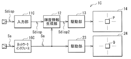
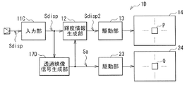
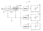
- the display device 1 includes an input unit 11, a luminance information generation unit 12, a drive unit 13, a display unit 14, a drive unit 23, and a display unit 24.
- the display device 1 performs display based on a signal Sin in which a video signal Sdisp and a transmission video signal Sa are multiplexed.
- the video signal Sdisp includes red (R) luminance information IR, green (G) luminance information IG, and blue (B) luminance information IB.
- the luminance information IR, IG, and IB indicate values of “0” or more and “1” or less, respectively.
- the value “0” indicates the minimum luminance (that is, black display), and the value “1” indicates the maximum luminance.
- the transmission video signal Sa includes transmission degree information ⁇ indicating the light transmission degree for each pixel.
- the transparency information ⁇ indicates a value not less than “0” and not more than “1”.
- the value “0” indicates non-transmission
- the value “1” indicates transmission.
- the value of the transmittance information ⁇ is set so that the light transmittance is low in a region corresponding to an image portion A in the frame image F indicated by the video signal Sdisp, as will be described later.
- the light transmission degree is set to be high in a region other than the region corresponding to the portion A.
- the input unit 11 is an input interface that receives the signal Sin.
- the input unit 11 separates the video signal Sdisp and the transmission video signal Sa from the signal Sin, supplies the video signal Sdisp to the luminance information generation unit 12, and transmits the transmission video signal Sa to the luminance information generation unit 12 and the driving unit.
- 23 also has a function of supplying to the terminal 23.
- the luminance information generation unit 12 generates the video signal Sdisp2 based on the video signal Sdisp and the transmission video signal Sa. Specifically, the luminance information generation unit 12 generates the luminance information IR2, IG2, IB2 based on the luminance information IR, IG, IB in a certain pixel and the transparency information ⁇ in the pixel, respectively. At that time, the luminance information generation unit 12 uses the luminance information IR, IG, IB as the luminance information IR2, IG2, IB2 as it is for a pixel having a sufficiently low value of the transmittance information ⁇ (a pixel having a sufficiently low light transmittance).
- the luminance information IR2, IG2, IB2 is generated by decreasing the values of the luminance information IR, IG, IB. That is, since the display unit 14 is a self-luminous device and a transmissive device as will be described later, the value of the luminance information is obtained in a pixel having a high value of the transmittance information ⁇ (a pixel having a high light transmittance). By reducing the value, the light transmission degree in the pixel P (described later) of the display unit 14 is increased.
- the luminance information generation unit 12 outputs the luminance information IR2, IG2, IB2 generated in this way as a video signal Sdisp2.
- the driving unit 13 drives the display unit 14 based on the video signal Sdisp2. Specifically, the drive unit 13 drives each pixel P (described later) of the display unit 14 by line-sequential scanning based on the video signal Sdisp2, and causes the display unit 14 to display based on the video signal Sdisp2. It has become.
- the display unit 14 is a so-called transmissive type in which the display area is configured to be transparent, and displays an image by self-emission based on driving by the driving unit 13.
- a display part 14 can be comprised using an organic EL element, an inorganic EL element, etc., for example.
- the display unit 14 is disposed in front of the display unit 24 so as to overlap the display unit 24.
- each pixel P includes a red (R) sub-pixel PsubR, a green (G) sub-pixel PsubG, and a blue (B) sub-pixel PsubB in this example.
- the display unit 14 displays an image by the sub pixels PsubR, PsubG, and PsubB emitting light with luminance corresponding to the luminance information IR2, IG2, and IB2.
- the drive unit 23 drives the display unit 24 based on the transmission video signal Sa. Specifically, the drive unit 23 drives each pixel Q (described later) of the display unit 24 by line-sequential scanning based on the transmission video signal Sa, and causes the display unit 24 to display based on the transmission video signal Sa. It is like that.
- the display unit 24 is a so-called transmission type in which the display area is configured to be transparent, and sets the light transmission degree based on the drive by the drive unit 23.
- a display part 24 can be comprised using a liquid crystal element, for example.
- the display unit 24 is disposed on the back side of the display unit 14 so as to overlap the display unit 14.
- the pixels Q are arranged in a matrix. Each pixel Q can set the light transmittance based on the transmittance information ⁇ . At that time, it is desirable that the pixel Q has a dark color such as black when the light transmission is sufficiently low. That is, in the pixel Q, the higher the value of the transmittance information ⁇ , the higher the light transmittance. The lower the value of the transmittance information ⁇ , the lower the light transmittance and the black color.
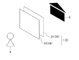
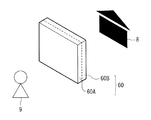
- FIG. 2 shows the arrangement with the display units 14 and 24.
- the display unit 14 and the display unit 24 are arranged so as to overlap each other.
- the display unit 14 is arranged on the display surface side observed by the user 9, and the display unit 24 is arranged on the back side of the display unit 14.
- the display unit 14 and the display unit 24 which are provided separately are arranged so as to overlap each other.
- each pixel Q in the display unit 24 corresponds to each pixel P in the display unit 14.
- the present invention is not limited to this, and instead, for example, each pixel Q in the display unit 24 may correspond to each of the plurality of pixels P in the display unit 14.
- the display device 1 can display characters and images superimposed on the scenery (such as house 8 in the example of FIG. 2) in the display areas of the display units 14 and 24. At that time, the display device 1 sets the luminance in each pixel P of the display unit 14 and sets the light transmittance in each pixel Q of the display unit 24 based on the transmittance information ⁇ . As a result, the display device 1 can improve the visibility regardless of the display contents and the environment in which the display device is used, as will be described later.
- the display unit 14 corresponds to a specific example of “first display unit” in the present disclosure.
- the display unit 24 corresponds to a specific example of “second display unit” in the present disclosure.
- the video signal Sdisp corresponds to a specific example of “video signal” in the present disclosure.
- the input unit 11 separates the video signal Sdisp and the transmission video signal Sa from the signal Sin, supplies the video signal Sdisp to the luminance information generation unit 12, and transmits the transmission video signal Sa to the luminance information generation unit 12 and the drive unit 23.
- the luminance information generator 12 generates a video signal Sdisp2 based on the video signal Sdisp and the transmitted video signal Sa.
- the drive unit 13 drives the display unit 14 based on the video signal Sdisp2.
- the display unit 14 displays an image by self-emission based on driving by the driving unit 13.
- the drive unit 23 drives the display unit 24 based on the transmission video signal Sa.
- the display unit 24 sets the light transmission degree for each pixel Q based on the drive by the drive unit 23.
- the display device 1 performs display based on a signal Sin obtained by multiplexing the video signal Sdisp and the transmission video signal Sa. At that time, the display device 1 sets the luminance in each pixel P of the display unit 14 and sets the light transmittance in each pixel Q of the display unit 24 based on the transmittance information ⁇ . The detailed operation of the display device 1 will be described below.
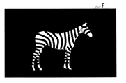
- FIG. 3 shows an example of the frame image F indicated by the video signal Sdisp.
- a striped horse is arranged near the center, and a portion other than the striped horse is represented in black.
- a portion where the striped horse is arranged in the frame image F will be described as an image portion A.
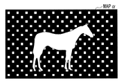
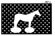
- FIG. 4 shows an example of map data MAP ⁇ of the transparency information ⁇ indicated by the transmission video signal Sa.
- a portion represented by white indicates that the value of the transparency information ⁇ is “0” (non-transparent), and a portion represented by black has a value of the transparency information ⁇ of “1” (transparent). ).
- the value of the transparency information ⁇ in the area corresponding to the image portion A is set to “0” (non-transparent).
- the value “1” and the value “0” of the transparency information ⁇ are set in a predetermined pattern.
- the average value of the light transmittance in the region other than the region corresponding to the image portion A is the area of the region where the value of the transmittance information ⁇ is “1” (transmitted) and the value of the transmittance information ⁇ is “0”. It becomes a value corresponding to the area ratio with the area of the region that is “non-transparent”.
- the transmittance information ⁇ is set so that the light transmittance is low in the region corresponding to the image portion A, and the light transmittance is high in the region other than the region corresponding to the image portion A. It is set as follows.
- the value of the transparency information ⁇ is set to “0” (non-transparent) in the area corresponding to the image part A, but the present invention is not limited to this, and the value in the area corresponding to the image part A is not limited thereto.
- Various settings can be made such that the light transmittance is lower than the light transmittance in a region other than the region corresponding to the image portion A.
- the value of the transparency information ⁇ may be a value indicating semi-transparency (for example, “0.2”), or the value “1” of the transparency information ⁇ . “0” may be set in a predetermined pattern.
- the value “1” and the value “0” of the transparency information ⁇ are set in a predetermined pattern in a region other than the region corresponding to the image portion A.
- the present invention is not limited to this.
- Various settings can be made such that the light transmittance in the region other than the region corresponding to the image portion A is higher than the light transmittance in the region corresponding to the image portion A.
- the pattern of the value “1” and the value “0” of the transparency information ⁇ may be different for each frame image F.
- the portions can be different.
- the value of the transparency information ⁇ is uniformly set to a value indicating semi-transparency (for example, “0.8”) or a value “1” (transmission). ) May be set.
- the luminance information generation unit 12 generates luminance information IR2, IG2, IB2 based on the luminance information IR, IG, IB included in the video signal Sdisp and the transparency information ⁇ included in the transmitted video signal Sa. Specifically, the luminance information generation unit 12 uses the luminance information IR, IG, and IB as the luminance information IR2, IG2, and IB2 as they are for the pixel having the low value of the transmittance information ⁇ (the pixel having the low light transmission degree), In a pixel having a high information ⁇ value (a pixel having a high light transmittance), the luminance information IR2, IG2, and IB2 are generated by decreasing the luminance information IR, IG, and IB, respectively.
- the display unit 14 is a self-luminous device and a transmissive device, the luminance information value is reduced in a pixel having a high value of the transmittance information ⁇ (a pixel having a high light transmittance).
- the light transmission degree in the pixel P of the display unit 14 is to be increased.
- the luminance information generation unit 12 generates the luminance information IR2, IG2, IB2 based on the luminance information IR, IG, IB and the transparency information ⁇ , and outputs it as the video signal Sdisp2.
- the driving unit 13 drives the display unit 14 based on the video signal Sdisp2, and the display unit 14 displays an image by self-light emission.
- the drive unit 23 drives the display unit 24 based on the transmission video signal Sa, and the display unit 24 sets the light transmission degree for each pixel Q.
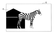
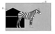
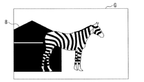
- FIG. 5A shows an observation image G observed by the user 9 in a bright environment such as daytime.
- the user 9 can observe the striped horse in the portion where the striped horse is arranged (image portion A), and the portion other than the portion where the striped horse is arranged (part other than the image portion A).
- the scenery on the other side of the display device 1 in this example, the house 8 in a bright environment
- the display unit 14 displays the luminance information included in the video signal Sdisp.
- Display is performed based on luminance information IR2, IG2, and IB2 equivalent to IR, IG, and IB, and the display unit 24 displays black by reducing the light transmission degree in this portion. Accordingly, the user 9 observes an image equivalent to the image indicated by the video signal Sdisp in the image portion A.
- the transmittance information ⁇ is high (the light transmittance is high), so the display units 14 and 24 transmit light in this portion. Increase the degree.
- the user 9 observes the scenery beyond the display device 1 (in this example, the house 8 in a bright environment) other than the image part A.
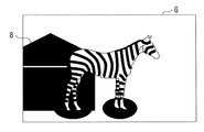
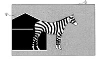
- FIG. 5B shows an observation image G observed by the user 9 in a dark environment such as evening.
- the user 9 can observe the striped horse at the portion where the striped horse is arranged (image portion A), and the portion other than the portion where the striped horse is arranged (part other than the image portion A).
- the scenery beyond the display device 1 in this example, the house 8 in a dark environment
- the display unit 14 displays the luminance information included in the video signal Sdisp.
- Display is performed based on luminance information IR2, IG2, and IB2 equivalent to IR, IG, and IB, and the display unit 24 displays black by reducing the light transmission degree in this portion. Accordingly, the user 9 observes an image equivalent to the image indicated by the video signal Sdisp in the image portion A.
- the transmittance information ⁇ is high (the light transmittance is high), so the display units 14 and 24 transmit light in this portion. Increase the degree.
- the user 9 observes the scenery beyond the display device 1 (in this example, the house 8 in a dark environment) other than the image part A.
- the luminance at each pixel P of the display unit 14 is set and the light transmittance at each pixel Q of the display unit 24 is set based on the transmittance information ⁇ .
- the user 9 can observe an image equivalent to the image indicated by the video signal Sdisp in the image portion A, and can observe a landscape beyond the display device 1 in a portion other than the image portion A. Visibility can be improved compared with the case of the comparative example shown below.
- the display device 1 can perform display only by supplying the transmitted video signal Sa in addition to the video signal Sdisp, when video content is produced, various past video resources are effectively used. be able to. That is, the transmitted video signal Sa has a smaller amount of data than the video signal Sdisp and is simple, and can be easily created based on the video signal Sdisp. Therefore, when the video content to be displayed on the display device 1 is produced, the transmission video signal Sa can be easily prepared based on various past video resources, so that these video resources can be used effectively. can do. Further, since the transmitted video signal Sa is simple with a small amount of data as described above, it can be produced with almost no burden when a new video content is produced.
- the display device 1 can express the characters and images so as to be merged with the scenery of the place by superimposing the characters and images on the actual landscape. It can provide unprecedented surprises.
- FIG. 6 illustrates a configuration example of the display device 1R according to the comparative example.
- the display device 1 ⁇ / b> R includes an input unit 11 ⁇ / b> R, a drive unit 13, and a display unit 14.
- the input unit 11 ⁇ / b> R is an input interface that receives the video signal Sdisp, and supplies the video signal Sdisp to the drive unit 13. That is, the display device 1R according to this comparative example is obtained by omitting the luminance information generation unit 12, the drive unit 23, and the display unit 24 from the display device 1 according to the present embodiment, and uses the transmission video signal Sa. Instead, display is performed based only on the video signal Sdisp.
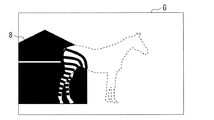
- FIG. 7 shows an observation image G observed by the user 9 in a bright environment such as daytime.
- display is performed based on the luminance information IR, IG, IB included in the video signal Sdisp.
- the black portion of the frame image F (FIG. 3)
- the display unit 14 which is a transmissive device
- the light transmission degree in these parts is high. Therefore, the user 9 observes the scenery on the other side of the display device 1 (in this example, the house 8 in a bright environment).
- the display unit 14 displays white by self-light emission. To do.
- the user 9 may not easily see the striped horse. That is, in this portion, the user 9 observes the white color due to the light emission of the display unit 14 in the white portion of the striped pattern of the striped horse. Moreover, since the display part 14 permeate
- the user 9 may have difficulty in visually checking the striped horse. That is, in this portion, the user 9 observes the white color due to the light emission of the display unit 14 in the white portion of the striped pattern of the striped horse. Moreover, since the display part 14 permeate
- the luminance at each pixel P of the display unit 14 is set and the light transmission level at each pixel Q of the display unit 24 is set based on the transmittance information ⁇ . I made it.
- the display unit 14 displays an image equivalent to the image indicated by the video signal Sdisp, and the display unit 24 reduces the light transmission degree.
- the display units 14 and 24 increase the light transmission degree.
- the user 9 can visually recognize the white and black striped pattern of the striped horse even in a bright environment such as the daytime.
- the display device 1 can improve the visibility regardless of the display contents and the environment in which the display device is used.
- the two display units 14 and 24 are provided, an image is displayed on the display unit 14, and the light transmission degree is set for each pixel in the display unit 24. Visibility can be enhanced regardless of the environment in which the is used.
- the visibility in each pixel of the display unit 14 is set and the light transmittance in each pixel of the display unit 24 is set based on the transmittance information, the visibility is improved. it can.
- display can be performed simply by supplying a transparent video signal in addition to a video signal. Therefore, various video resources in the past can be used effectively when producing video content. be able to.
- the portion where the striped horse is arranged is the image portion A, but the present invention is not limited to this, and the image portion A can be arbitrarily set. Below, an example of this modification is demonstrated in detail.
- FIG. 8 shows an example of map data MAP ⁇ of the transparency information ⁇ indicated by the transmitted video signal Sa.
- a wider part including the part where the striped horse is arranged is set as the image part A.
- the image portion A not only the portion where the striped horse is arranged but also the portion around the leg of the striped horse is set as the image portion A.
- FIG. 9A shows the observation image G observed by the user 9 in a bright environment
- FIG. 9B shows the observation image G observed by the user 9 in a dark environment.
- the user 9 can observe the display based on the video signal Sdisp in the vicinity of the striped horse and the legs of the striped horse, and in other parts, observe the landscape on the other side of the display device. Can do.
- the wider part including the part where the striped horse is arranged is set as the image part A.
- the present invention is not limited to this.
- only a part (for example, a face) of the striped horse is used instead. May be set as the image portion A.
- the luminance information generation unit 12 generates the video signal Sdisp2 based on the transmission video signal Sa, and the drive unit 23 drives the display unit 24 based on the transmission video signal Sa. Not what you want.
- a filter unit 15B that performs a filtering process on the transmitted video signal Sa to generate the transmitted video signal Sb is provided.
- the video signal Sdisp2 may be generated based on the video signal Sdisp and the transmission video signal Sb, and the drive unit 23 may drive the display unit 24 based on the transmission video signal Sb.
- the filter unit 15B performs a smoothing process (so-called anti-aliasing process) on the map data MAP ⁇ indicated by the transmission video signal Sa, and transmits the transparency information between the image part A and other parts. ⁇ can be changed smoothly.
- the filter unit 15B can be configured using, for example, a FIR (Finite Impulse Response) filter.
- the filter unit 15B is provided in the display device 1B.
- the present invention is not limited to this.
- the display device is configured without the filter unit 15B, and such filter processing is performed.
- the transmission video signal Sb may be multiplexed with the video signal Sdisp and supplied to the display device.
- FIG. 11 shows one configuration example of the display device 1C according to this modification.
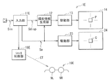
- the display device 1C performs display based on the video signal Ssisp and the transmission video signal Sa supplied separately.
- the display device 1C includes an input unit 11C and a network interface 16C.
- the input unit 11 ⁇ / b> C is an input interface that receives the video signal Sdisp, and supplies the received video signal Sdisp to the luminance information generation unit 12.
- the network interface 16C is a LAN (Local Area Network) interface, and is connected to the Internet.
- a video signal Sdisp is supplied from a DVD (registered trademark) player.
- the display device 1C acquires a transmission video signal Sa corresponding to the video signal Sdisp from a server on the Internet. Then, the display device 1C performs display based on the video signal Ssisp and the transmission video signal Sa acquired in this way.
- FIG. 12 shows a configuration example of another display device 1D according to this modification.
- the display device 1D includes a transmission video signal generation unit 17D.
- the transmission video signal generation unit 17D generates the transmission video signal Sa based on the video signal Sdisp supplied from the input unit 11C, and supplies the transmission video signal Sa to the luminance information generation unit 12 and the drive unit 23. is there.
- the transmission video signal generation unit 17D detects, for example, pattern recognition or the like in the frame image F indicated by the video signal Sdisp, for example, the main display object in the frame image F such as a person or an animal. Then, the transmission video signal generation unit 17D sets a portion where the display object is arranged in the frame image F as an image portion A, and generates a transmission video signal Sa.
- the transmission video signal generation unit 17D sets the value of the transmittance information ⁇ so that the light transmittance is low in the region corresponding to the image portion A, and the region other than the region corresponding to the image portion A. Is set so that the light transmittance is high.
- the display device 1D can generate the transmission video signal Sa based on the video signal Sdisp even when the transmission video signal Sa is not supplied. The effect of can be obtained. Thereby, in the display device 1D, various past video resources can be used as they are.
- FIG. 13 shows a configuration example of the display device 1E according to this modification.
- the display device 1E is an active shutter type stereoscopic display device.
- the display device 1E includes an input unit 11E, a shutter control unit 18E, and shutter glasses 19E. Similar to the input unit 11, the input unit 11E is an input interface that receives the signal Sin, and separates the video signal Sdisp and the transmitted video signal Sa from the signal Sin.
- the video signal Sdisp includes luminance information IR, IG, IB relating to the left eye image FL and luminance information IR, IG, IB relating to the right eye image FR, and the transmitted video signal Sa.
- Map data MAP ⁇ corresponding to the left eye image FL and map data MAP ⁇ corresponding to the right eye image FL.
- the input unit 11E also has a function of supplying a control signal to the shutter control unit 18E.
- the shutter control unit 18E generates a shutter control signal CTL based on the control signal supplied from the input unit 11E, and supplies the shutter control signal CTL to the shutter glasses 19E through wireless communication.
- the shutter control unit 18E supplies the shutter control signal CTL by wireless communication.
- the present invention is not limited to this, and may be supplied by wired communication, for example.
- the shutter glasses 19E are eyeglass-type shutter devices, and enable stereoscopic viewing when used by a user 9 (not shown).
- the shutter glasses 19E have a left eye shutter 9L and a right eye shutter 9R.
- the left eye shutter 9L and the right eye shutter 9R are constituted by, for example, liquid crystal shutters.
- the transmission state (open state) and light shielding state (closed state) of the left eye shutter 9L and right eye shutter 9R are controlled by a shutter control signal CTL supplied from the shutter control unit 18E.
- FIG. 14 schematically shows the stereoscopic display operation in the display device 1E.
- the display units 14 and 24 alternately display the left eye image FL and the right eye image FR on the time axis.
- the left eye shutter 9L is opened and the right eye shutter 9R is closed.
- the user 9 observes the left eye image FL with the left eye.
- the display units 14 and 24 display the right eye image FR
- the left eye shutter 9L is closed and the right eye shutter 9R is opened.
- the user 9 observes the right eye image FR with the right eye. If these operations are repeated alternately, there is a parallax between the left eye image FL and the right eye image FR, and thus the user recognizes a video composed of these series of images as a stereoscopic video with depth. be able to.
- FIG. 15 illustrates a configuration example of another display device 1F according to the present modification
- FIG. 16 schematically illustrates a stereoscopic display operation in the display device 1F.
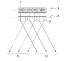
- the display device 1F is a lenticular lens type stereoscopic display device.
- the display device 1F includes a lenticular sheet 31 as shown in FIG.
- the lenticular sheet 31 is disposed in front of the display unit 14.
- the lenticular sheet 31 has convex lenses (lenticular lenses LL) curved in the horizontal direction arranged in parallel in the horizontal direction.
- Each lenticular lens LL in the lenticular sheet 31 is provided so as to correspond to the two pixels P in the display unit 14 in the horizontal direction.
- Each pixel P of the display unit 14 alternately performs display based on the luminance information IFL related to the left eye image FL and display based on the luminance information IFR related to the right eye image FR in the horizontal direction.
- each pixel Q of the display unit 24 includes a display based on the transmittance information ⁇ FL related to the left eye image FL and a display based on the transmittance information ⁇ FR related to the right eye image FR in the horizontal direction. Alternately. With this configuration, light based on the luminance information IFL is refracted by the lenticular lens LL and proceeds in the lower left direction in FIG.
- the user 9 observes the light based on the luminance information IFL with the left eye as the left eye image FL, and observes the light based on the luminance information IFR with the right eye as the right eye image FR.
- the user 9 can recognize the video displayed on the display device 1F as a stereoscopic video.
- FIG. 17 schematically illustrates an operation of stereoscopic display in the other display device 1G according to the present modification.
- the display device 1G is a parallax barrier type stereoscopic display device.
- the stereoscopic display device 1G includes a parallax barrier 32 as shown in FIG.
- the ballax barrier 32 is disposed in front of the display unit 14.
- the parallax barrier 32 includes barriers BB that do not allow light to pass in parallel in the horizontal direction.
- Each barrier BB in the parallax barrier 32 is provided so as to correspond to the two pixels P in the display unit 14 in the horizontal direction.
- Each pixel P of the display unit 14 alternately performs display based on the luminance information IFL related to the left eye image FL and display based on the luminance information IFR related to the right eye image FR in the horizontal direction.
- each pixel Q of the display unit 24 includes a display based on the transmittance information ⁇ FL related to the left eye image FL and a display based on the transmittance information ⁇ FR related to the right eye image FR in the horizontal direction. Alternately. With this configuration, the light based on the luminance information IFL travels in the lower left direction in FIG. 17 with the travel direction being restricted by the barrier BB, and the light based on the brightness information IFR is traveled in the right direction in FIG. Proceed downward.
- the user 9 observes the light based on the luminance information IFL with the left eye as the left eye image FL, and observes the light based on the luminance information IFR with the right eye as the right eye image FR.
- the user 9 can recognize the video displayed on the display device 1G as a stereoscopic video.
- the display device 1 is configured using the two display units 14 and 24.
- the display device 1 is not limited to this, and instead, for example, the display device 1H is configured using three display units. May be configured. Below, this modification is demonstrated in detail.
- FIG. 18 illustrates a configuration example of the display device 1H.
- the display device 1H includes a display unit 34 and a drive unit 33.
- FIG. 19 shows the arrangement of the display units 14, 24, and 34 in the display device 1H.
- the display unit 34 is a so-called transmissive type whose display area is configured to be transparent, like the display unit 14, and displays an image by self-emission based on driving by the driving unit 33.
- the display unit 34 is disposed on the other side of the display unit 24 so as to overlap the display unit 24. That is, the display device 1H is configured such that the user 9A on the display unit 14 side can observe the image and the user 9B on the display unit 34 side can observe the image.
- the display unit 34 has pixels R arranged in a matrix. In this example, each pixel R in the display unit 34 corresponds to each pixel Q in the display unit 24.
- the display unit 34 corresponds to a specific example of “third display unit” in the present disclosure.
- the drive unit 33 drives the display unit 34 based on the video signal Sdisp2. Specifically, the drive unit 33 drives each pixel R of the display unit 34 by line sequential scanning based on the video signal Sdisp2, and causes the display unit 34 to display based on the video signal Sdisp2. . At that time, the drive unit 33 causes the display unit 34 to display an image obtained by inverting the image displayed on the display unit 14 in the horizontal direction. As a result, the image observed by the user 9A is obtained by inverting the image observed by the user 9B in the horizontal direction.
- the visibility can be improved regardless of the display contents and the environment in which the display device is used, and the user can observe images from both sides.
- the display units 14 and 34 display images that are reversed with each other.
- the present invention is not limited to this, and may be configured to display different images.
- two images obtained by shooting a subject from different directions can be displayed on the display units 14 and 34, respectively.
- the display unit 14 displays an image of the person viewed from the front
- the display unit 34 displays an image of the person viewed from the back.
- the display device 1H can perform display with higher reality.
- the display units 14 and 24 perform display based on the transmission video signal Sa supplied from the outside.
- the present invention is not limited to this.
- a display mode M may be provided so that the display operation can be changed. Below, this modification is demonstrated in detail.
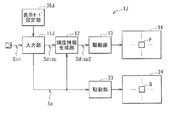
- FIG. 20 illustrates a configuration example of the display device 1J according to the present modification.
- the display device 1J includes a display mode setting unit 35J and an input unit 11J.
- the display device 1J has two display modes M1 and M2.
- the display mode setting unit 35 selects one of the display modes M1 and M2 based on an operation by the user, and transmits the selection result to the input unit 11J.
- the input unit 11J separates the video signal Sdisp and the transmitted video signal Sa from the signal Sin and generates the luminance information of the video signal Sdisp as in the case of the above embodiment.
- the transmission video signal Sa is supplied to the luminance information generation unit 12 and the driving unit 23.
- the input unit 11J separates the video signal Sdisp and the transmission video signal Sa from the signal Sin, and supplies the video signal Sdisp to the luminance information generation unit 12 to transmit the transmission video.
- All the values of the transparency information ⁇ in the signal Sa are replaced with “0” (non-transparent), and the replaced transmission video signal Sa is supplied to the luminance information generating unit 12 and the driving unit 23.
- the display unit 14 performs display based on the luminance information IR2, IG2, and IB2 equivalent to the luminance information IR, IG, and IB included in the video signal Sdisp, and the display unit 24 displays the entire screen in a non-transparent state.
- the user 9 can observe an image equivalent to the frame image F indicated by the video signal Sdisp (for example, the frame image F in FIG. 3) on the entire display screen.
- the luminance information generation unit 12 is provided to generate the video signal Sdisp2 based on the video signal Sdisp and the transmission video signal Sa.
- the present invention is not limited to this, and instead, for example, the luminance information generation unit 12 may be omitted, and the driving unit 13 may be configured to operate based on the video signal Sdisp.
- the display part 14 and the display part 24 were comprised as a different body, respectively, and arrange
- a display unit 60A corresponding to the display unit 14 and a display unit 60B corresponding to the display unit 24 are integrally formed.
- the pixel P and the pixel Q are stacked.
- the display device 2 according to the second embodiment will be described.
- the display unit on the user 9 side of the two display units is configured as a non-light emitting display unit.
- symbol is attached
- the display device 2 includes a display unit 44, a display unit 54, and a luminance information generation unit 42.
- the display unit 44 is a so-called transmission type whose display area is configured to be transparent, and displays an image by setting the light transmission degree based on the drive by the drive unit 13.
- a display part 44 can be comprised using a liquid crystal element, for example.
- the display unit 44 is disposed in front of the display unit 54 so as to overlap the display unit 54.
- the pixels P are arranged in a matrix.
- each pixel P includes a red (R) sub-pixel PsubR, a green (G) sub-pixel PsubG, and a blue (B) sub-pixel PsubB in this example.
- the subpixel PsubR has a red color filter
- the subpixel PsubG has a green color filter
- the subpixel PsubB has a blue color filter.
- the display unit 44 displays an image by setting the light transmittance in these sub-pixels PsubR, PsubG, and PsubB according to the luminance information IR2, IG2, and IB2.
- the display unit 54 is a so-called transmission type whose display region is configured to be transparent, and emits white light based on driving by the driving unit 23.
- a display part 54 can be comprised using an organic EL element, an inorganic EL element, etc., for example.
- the present invention is not limited to this, and any transmissive type that can emit white light may be used.
- a technique used in a field emission display (FED) Etc. may be applied.
- a white light can be displayed by further providing a light source and irregularly reflecting the light emitted from the light source by the light control sheet.
- the phosphor that emits white light for example, a phosphor that includes a phosphor capable of emitting light in a wide wavelength range near blue and a phosphor capable of emitting light in a wide wavelength range near yellow is used. it can.
- the display unit 54 is disposed on the back side of the display unit 44 so as to overlap the display unit 44.
- pixels Q are arranged in a matrix. Each pixel Q can set the brightness of white light based on the transmittance information ⁇ . That is, in the pixel Q, the higher the value of the transmittance information ⁇ , the lower the luminance and the higher the light transmittance, and the lower the value of the transmittance information ⁇ , the higher the luminance of white light.
- the luminance information generation unit 42 generates the video signal Sdisp2 based on the video signal Sdisp and the transmission video signal Sa, similarly to the luminance information generation unit 12 according to the first embodiment. Specifically, the luminance information generation unit 42 generates luminance information IR2, IG2, IB2 based on the luminance information IR, IG, IB in a certain pixel and the transparency information ⁇ in the pixel, respectively.
- the luminance information generation unit 42 uses the luminance information IR, IG, IB as the luminance information IR2, IG2, IB2 as it is for a pixel having a sufficiently low value of the transmittance information ⁇ (a pixel having a sufficiently low light transmittance), In a pixel having a high value of the transmittance information ⁇ (a pixel having a high light transmittance), the luminance information IR2, IG2, IB2 is generated by increasing the values of the luminance information IR, IG, IB.
- the display unit 44 is a device configured to be able to change the light transmittance, by increasing the value of the luminance information in a pixel having a high value of the transmittance information ⁇ (a pixel having a high light transmittance).
- the light transmission degree in the pixel P of the display unit 44 is to be increased.
- the luminance information generation unit 42 outputs the luminance information IR2, IG2, IB2 generated in this way as a video signal Sdisp2.
- the display unit 44 corresponds to a specific example of “first display unit” in the present disclosure.
- the display unit 54 corresponds to a specific example of “second display unit” in the present disclosure.
- the display device 2 performs display based on the signal Sin in which the video signal Sdisp and the transmission video signal Sa are multiplexed. At that time, the display device 2 sets the light transmittance in each pixel P of the display unit 44 and sets the luminance of white light in each pixel Q of the display unit 54 based on the transmittance information ⁇ .
- the display device 2 sets the light transmittance in each pixel P of the display unit 44 and sets the luminance of white light in each pixel Q of the display unit 54 based on the transmittance information ⁇ .
- FIG. 22A shows an observation image G observed by the user 9 in a bright environment such as daytime.
- the user 9 can observe the striped horse in the portion where the striped horse is arranged (image portion A), and the portion other than the portion where the striped horse is arranged (part other than the image portion A).
- the scenery beyond the display device 2 in this example, the house 8 in a bright environment
- the display unit 44 displays the luminance information included in the video signal Sdisp.
- Display is performed based on luminance information IR2, IG2, and IB2 equivalent to IR, IG, and IB, and the display unit 54 increases the luminance of white light in this portion. Accordingly, the user 9 observes an image equivalent to the image indicated by the video signal Sdisp in the image portion A.
- the portion other than the portion where the striped horse is arranged has a high value of the transmittance information ⁇ (the light transmittance is high). Increase the degree. Thereby, the user 9 observes the scenery beyond the display device 2 (in this example, the house 8 in a bright environment) other than the image part A.
- FIG. 22B shows an observation image G observed by the user 9 in a dark environment such as evening.
- the user 9 can observe the striped horse at the portion where the striped horse is arranged (image portion A), and the portion other than the portion where the striped horse is arranged (part other than the image portion A).
- a landscape beyond the display device 2 in this example, a house 8 in a dark environment
- the display unit 44 displays the luminance information included in the video signal Sdisp.
- Display is performed based on luminance information IR2, IG2, and IB2 equivalent to IR, IG, and IB, and the display unit 54 increases the luminance of white light in this portion. Accordingly, the user 9 observes an image equivalent to the image indicated by the video signal Sdisp in the image portion A.
- the display units 44 and 54 transmit light in this portion. Increase the degree. Thereby, the user 9 observes the scenery beyond the display device 2 (in this example, the house 8 in a dark environment) other than the image part A.
- the luminance at each pixel P of the display unit 44 is set and the light transmission level at each pixel Q of the display unit 54 is set based on the transmittance information ⁇ .
- the user 9 can observe an image equivalent to the image indicated by the video signal Sdisp in the image portion A, and can observe a landscape beyond the display device 2 in a portion other than the image portion A. Visibility can be improved compared with the case of the comparative example shown below.
- the display device 2 ⁇ / b> R according to the comparative example includes an input unit 11 ⁇ / b> R, a drive unit 13, and a display unit 44.
- the display device 2R according to the comparative example is obtained by omitting the luminance information generation unit 42, the drive unit 23, and the display unit 54 from the display device 2 according to the present embodiment, and without using the transmission video signal Sa. The display is performed based only on the video signal Sdisp.
- FIG. 23 shows an observation image G observed by the user 9 in a dark environment such as evening.
- display is performed based on the luminance information IR, IG, IB included in the video signal Sdisp.
- the white part of the frame image F (FIG. 3)
- the brightness information IR, IG, and IB are high, so that the light transmission degree can be changed.
- the display unit 44 which is a device
- the light transmission degree in these parts becomes high. Therefore, the user 9 observes the scenery on the other side of the display device 2 (in this example, the house 8 in a dark environment).
- the black portion of the frame image F (FIG. 3), that is, the black portion in the striped pattern of the striped horse and the portion other than the striped horse, the values of the luminance information IR, IG, IB are low. The light transmission is lowered and black is displayed.
- the user 9 may not easily see the striped horse. That is, in this portion, in the black portion of the striped pattern of the striped horse, the user 9 observes the black color due to the low light transmittance in the display unit 44. In the white portion of the striped pattern of the striped horse, the user 9 observes the scenery (house 8) on the other side of the display device 2 through the display unit 44. At this time, since the difference between the black color displayed on the display unit 44 and the black color of the environment is small, the user 9 may not easily see the striped horse.
- the user 9 may not easily see the striped horse. That is, in this portion, in the black portion of the striped pattern of the striped horse, the user 9 observes the black color due to the low light transmittance in the display unit 44. Moreover, since the display part 44 permeate
- the light transmission degree in each pixel P of the display unit 44 is set based on the transmittance information ⁇ , and the luminance of white light in each pixel Q of the display unit 54 is set. I set it.
- the display unit 44 displays an image equivalent to the image indicated by the video signal Sdisp, and the display unit 54 displays the brightness of the white light. Make it high.
- the display units 44 and 54 increase the light transmission degree in portions other than the portion where the striped horse is arranged. Thereby, as shown in FIG. 22B, the user 9 can visually recognize the white and black striped pattern of the striped horse even in a dark environment such as evening.
- the display device 2 can improve the visibility regardless of the display contents and the environment in which the display device is used.
- the light transmission degree in each pixel P of the display unit 44 is set based on the transmittance information, and the luminance of white light in each pixel Q of the display unit 54 is set. Therefore, visibility can be improved regardless of the display content and the environment in which the display device is used. Other effects are the same as in the case of the first embodiment.
- each pixel Q of the display unit 54 emits light.
- each pixel Q is configured to reflect light. May be.
- the pixel Q can be configured such that the light reflection degree can be changed according to the value of the transmittance information ⁇ . In this case, in the pixel Q, the higher the value of the transmission information ⁇ , the lower the light reflection degree and the higher the light transmission degree, and the lower the value of the transmission information ⁇ , the higher the light reflection degree.
- an electrochemical solution containing silver ions between an ITO (Indium Tin Oxide) film having a flat surface and an ITO film having a rough surface As a device capable of changing the light transmission degree and the light reflection degree as described above, for example, an electrochemical solution containing silver ions between an ITO (Indium Tin Oxide) film having a flat surface and an ITO film having a rough surface.
- positioned is mentioned.
- the display device displays an image equivalent to the image indicated by the video signal Sdisp in the image portion A, as in the so-called reflective display device. Therefore, the user 9 can observe an image equivalent to the image indicated by the video signal Sdisp in the image portion A, and can observe a landscape beyond the display device 2 in a portion other than the image portion A. it can.
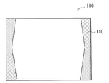
- FIG. 24 illustrates an operation example of the television device 100 to which the display device of the above-described embodiment or the like is applied.
- the television apparatus 100 is configured as a window glass of a building.
- the television device 100 has two display modes N1 and N2.
- the operation will be described by taking the case where the display device 1 is applied as an example.
- the television device 100 displays the curtain 110, for example, as shown in FIG.
- the curtain 110 is set as the image portion A.
- both the display parts 14 and 24 will be in a transmissive state. That is, in a portion other than the image portion A, the television device 100 functions as a normal window glass.
- the television device 100 displays the broadcast video.
- the display unit 14 performs display based on luminance information IR2, IG2, IB2 equivalent to the luminance information IR, IG, IB included in the broadcast video signal Sdisp, and the display unit 24 includes: Black color is displayed by making the entire screen opaque.
- the user 9 can observe an image equivalent to the frame image F (for example, the frame image F in FIG. 3) indicated by the broadcast video signal Sdisp on the entire display screen.
- the curtain 110 can be opened and closed by providing a touch panel in the television device 100 and sliding the finger while the finger is touching the touch panel in the display mode N1. At that time, when the curtain 110 is closed, the color of the curtain 110 may be set to a slightly dark color. Thus, in the television apparatus 100, the shape and color of the curtain can be freely changed by the user operating the touch panel.
- the pixels other than the curtain 110 may be caused to emit light so as to function as an illumination device.
- the user can feel like a bright and clear day even on a dark rainy day, and can feel like a daytime even in the evening.
- the curtain 110 is displayed.
- the present invention is not limited to this.
- a blind or a roll screen may be displayed.
- the television device is configured as a window glass of a building.
- the present invention is not limited to this.
- the television device may be configured as a window glass of a car.
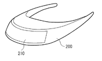
- FIG. 25 shows the appearance of a head mounted display to which the display device of the above-described embodiment or the like is applied.
- the head mounted display includes, for example, a main body unit 200 and a display screen unit 210.
- the display screen unit 210 is configured using the display device according to the above-described embodiment and the like.
- the display devices of the above-described embodiments are electronic devices in all fields such as computer displays, video monitors, home cinema displays, flexible displays, commercial displays, industrial displays, head-up displays, watches, electronic billboards, etc. It can be applied to equipment.
- the display device according to the above embodiment and the like can be applied to electronic devices in all fields that display images.
- the display device 1 and the like perform display based on the signal Sin obtained by multiplexing the video signal Sdisp and the transmission video signal Sa. It may be recorded on a recording medium. Further, when the display device 1 or the like is applied to a television device, the signal Sin may be supplied by a broadcast wave.
Abstract
This display device has the following: a first display unit that, for pixels in partial regions corresponding to some image sections of frame images that a video signal represents, displays video corresponding to said video signal, and for pixels in regions other than said partial regions, remains transparent; and a second display unit that is positioned behind the first display unit, displays a uniform or non-uniform dummy image for the pixels in the partial regions, and remains transparent for the pixels in the regions other than said partial regions.
Description
本発明は、画像を表示する表示装置、およびそのような表示装置で用いられる表示方法に関する。
The present invention relates to a display device for displaying an image and a display method used in such a display device.
近年、表示部を透明な材料で構成した、いわゆるシースルーディスプレイが開発されている。このような透過型の表示部を有する表示装置では、通常の表示装置と異なり、現実の風景に文字や画像を重畳して表示することができる。このような表示装置は、例えば、AR(Augmented Reality)など、様々な用途に用いられることが期待される。
In recent years, so-called see-through displays have been developed in which the display section is made of a transparent material. Unlike a normal display device, a display device having such a transmissive display unit can display characters and images superimposed on an actual landscape. Such a display device is expected to be used for various purposes such as AR (Augmented Reality).
このような透過型の表示部は、例えば、有機EL(Electro Luminescence)素子、無機EL素子、液晶素子などを用いたものが開発されている。例えば、特許文献1には、有機EL素子を用いて透過型の表示部を構成した表示装置が開示されている。また、例えば非特許文献1には、このような有機EL素子に使用可能な透明導電材料が開示されている。
Such a transmissive display unit has been developed using, for example, an organic EL (Electro Luminescence) element, an inorganic EL element, a liquid crystal element, or the like. For example, Patent Document 1 discloses a display device in which a transmissive display unit is configured using an organic EL element. Further, for example, Non-Patent Document 1 discloses a transparent conductive material that can be used for such an organic EL element.
このような透過型の表示部を有する表示装置では、例えば、表示内容や、表示装置を使用する環境によって、視認性が低下するおそれがある。例えば、有機EL素子を用いて透過型の表示部を構成し、暗い画像を明るい環境で表示する場合には、画像のうちの暗い部分が透過してしまうため、ユーザは、本来暗い画像を表示すべき部分に、明るい環境での風景を観察してしまう。また、例えば、液晶素子を用いて透過型の表示部を構成し、明るい画像を暗い環境で表示する場合には、画像のうちの明るい部分が透過してしまうため、ユーザは、本来明るい画像を表示すべき部分に、暗い環境での風景を観察してしまう。このように、これらの表示装置では、表示内容や、表示装置を使用する環境によっては、ユーザは、表示装置が表示しようとする画像を視認できないおそれがある。よって、透過型の表示部を有する表示装置では、表示内容や、表示装置を使用する環境によらず、高い視認性を実現できることが望まれる。
In a display device having such a transmissive display unit, the visibility may be lowered depending on, for example, display contents and the environment in which the display device is used. For example, when a transmissive display unit is configured using an organic EL element and a dark image is displayed in a bright environment, a dark portion of the image is transmitted, so that the user originally displays a dark image. Observe the scenery in a bright environment where it should be. Further, for example, when a transmissive display unit is configured using a liquid crystal element and a bright image is displayed in a dark environment, a bright part of the image is transmitted. A scene in a dark environment is observed in a portion to be displayed. As described above, in these display devices, depending on the display contents and the environment in which the display device is used, the user may not be able to visually recognize the image that the display device intends to display. Therefore, in a display device having a transmissive display portion, it is desired that high visibility can be realized regardless of display contents and an environment in which the display device is used.
したがって、本発明の目的は、表示内容や、表示装置を使用する環境によらず、視認性を高めることができる表示装置および表示方法を提供することにある。
Therefore, an object of the present invention is to provide a display device and a display method capable of improving visibility regardless of display contents and an environment in which the display device is used.
本発明の一実施形態における表示装置は、第1の表示部と、第2の表示部とを備えている。第1の表示部は、映像信号が示すフレーム画像のうちの一部の画像部分に対応する部分領域の画素については映像信号に応じた映像表示を行い、部分領域以外の領域の画素については透過性表示を行うものである。第2の表示部は、第1の表示部の背面側に配置され、部分領域の画素については一様または非一様なダミー画像を表示し、部分領域以外の領域の画素については透過性表示を行うものである。ここで、「映像信号に応じた映像表示」は、映像信号が示す部分画像をそのまま表示することの他、その部分画像を、光透過度合いをやや高めて表示することをも含むものである。「透過性表示」は、完全な透明表示には限られず、光透過度合いをやや低下させた表示をも含むものである。また、「ダミー画像」の表示は、完全な不透明状態での表示には限られず、光透過度合いをやや高めた表示をも含むものである。
The display device according to an embodiment of the present invention includes a first display unit and a second display unit. The first display unit performs video display according to the video signal for the pixels in the partial area corresponding to a part of the image portion of the frame image indicated by the video signal, and transmits the pixels in the area other than the partial area. It is a sex display. The second display unit is disposed on the back side of the first display unit, and displays a uniform or non-uniform dummy image for the pixels in the partial region, and transmissive display for the pixels in the region other than the partial region. Is to do. Here, “video display according to the video signal” includes not only displaying the partial image indicated by the video signal as it is, but also displaying the partial image with a slightly increased degree of light transmission. “Transparent display” is not limited to complete transparent display, but also includes display in which the degree of light transmission is slightly reduced. Further, the display of the “dummy image” is not limited to display in a completely opaque state, but includes display with a slightly increased degree of light transmission.
本発明の一実施形態における表示方法は、第1の表示部において、映像信号が示すフレーム画像のうちの一部の画像部分に対応する部分領域の画素については映像信号に応じた映像表示を行い、部分領域以外の領域の画素については透過性表示を行い、第1の表示部の背面側に配置された第2の表示部において、部分領域の画素については一様または非一様なダミー画像を表示し、部分領域以外の領域の画素については透過性表示を行うものである。
In the display method according to an embodiment of the present invention, the first display unit performs video display according to the video signal for pixels in a partial region corresponding to a partial image portion of the frame image indicated by the video signal. A transparent image is displayed for pixels in areas other than the partial area, and a dummy image in which the pixels in the partial area are uniform or non-uniform in the second display section disposed on the back side of the first display section. Is displayed, and the transmissive display is performed for the pixels in the region other than the partial region.
本発明の一実施形態における表示装置および表示方法では、第1の表示部と第2の表示部において表示が行われる。その際、第1の表示部では、画像部分に対応する部分領域の画素については映像信号に応じた映像表示が行われ、部分領域以外の領域の画素については透過性表示が行われる。また、第2の表示部では、部分領域に対応する領域の画素については一様または非一様なダミー画像が表示され、部分領域以外の領域の画素については透過性表示が行われる。
In the display device and the display method according to the embodiment of the present invention, display is performed on the first display unit and the second display unit. At this time, in the first display unit, video display according to the video signal is performed for the pixels in the partial area corresponding to the image portion, and transmissive display is performed for the pixels in the area other than the partial area. In the second display unit, a uniform or non-uniform dummy image is displayed for pixels in a region corresponding to the partial region, and transmissive display is performed for pixels in a region other than the partial region.
本発明の一実施形態における表示装置では、例えば、第1の表示部および第2の表示部は、画素単位の光透過度合を示す透過映像信号に基づいて透過性表示を行うことが望ましい。例えば、透過映像信号は、部分領域における光透過度合および部分領域以外の領域における光透過度合を含み、第1の表示部は、部分領域における光透過度合に基づいて映像表示を行うとともに、部分領域以外の領域における光透過度合に基づいて透過性表示を行い、第2の表示部は、部分領域における光透過度合に基づいてダミー画像を表示するとともに、部分領域以外の領域における光透過度合に基づいて透過性表示を行うようにしてもよい。この場合、例えば、部分領域における透過映像信号が示す平均光透過度合は、部分領域以外の領域における透過映像信号が示す平均光透過度合よりも低いことが望ましい。例えば、光透過度合は、部分領域以外の領域において一様でなくてもよいし、一様であってもよい。また、例えば、透過映像信号に対してフィルタ処理を行うフィルタ部をさらに備え、第1の表示部および第2の表示部は、フィルタ処理が行われた透過映像信号に基づいて透過性表示を行うようにしてもよい。
In the display device according to the embodiment of the present invention, for example, it is desirable that the first display unit and the second display unit perform transmissive display based on a transmission video signal indicating the light transmission degree in units of pixels. For example, the transmission video signal includes a light transmission degree in the partial area and a light transmission degree in an area other than the partial area, and the first display unit performs video display based on the light transmission degree in the partial area. The second display unit displays a dummy image based on the light transmission degree in the partial area, and displays the dummy image based on the light transmission degree in the area other than the partial area. Thus, transmissive display may be performed. In this case, for example, it is desirable that the average light transmission degree indicated by the transmission video signal in the partial area is lower than the average light transmission degree indicated by the transmission video signal in the area other than the partial area. For example, the light transmittance may not be uniform in a region other than the partial region, or may be uniform. In addition, for example, a filter unit that performs a filtering process on the transmission video signal is further provided, and the first display unit and the second display unit perform a transmissive display based on the transmission video signal on which the filtering process has been performed. You may do it.
例えば、映像信号および透過映像信号は互いに多重化され、多重化された映像信号および透過映像信号を受け取る入力部をさらに備えてもよい。もしくは、例えば、映像信号を受け取る第1の入力部と、透過映像信号を受け取る第2の入力部とをさらに備えてもよい。この場合、第2の入力部をネットワークインタフェースを用いて構成し、透過映像信号をインターネットを介して供給するようにすることができる。また、映像信号に基づいて透過映像信号を生成する透過映像信号生成部をさらに備えてもよい。
For example, the video signal and the transmission video signal may be multiplexed with each other, and an input unit that receives the multiplexed video signal and the transmission video signal may be further provided. Alternatively, for example, a first input unit that receives a video signal and a second input unit that receives a transmission video signal may be further provided. In this case, the second input unit can be configured using a network interface, and the transmitted video signal can be supplied via the Internet. Moreover, you may further provide the transmission video signal generation part which produces | generates a transmission video signal based on a video signal.
第1の表示部および第2の表示部は、例えば、以下のような構成にすることができる。すなわち、第1の表示部を自発光型の表示部を用いて構成し、第2の表示部を非発光型の表示部を用いて構成することができる。また、第1の表示部を非発光型の表示部を用いて構成し、第2の表示部を自発光型の表示部を用いて構成してもよい。さらに、第1の表示部を非発光型の表示部を用いて構成し、第2の表示部を、選択反射型の表示部を用いて構成してもよい。ここで、選択反射型の表示部は、例えば、表示面から入射した光を画素単位で反射可能に構成されたものである。また、例えば、第1の表示部および第2の表示部を、一体として形成してもよい。
The first display unit and the second display unit can be configured as follows, for example. That is, the first display unit can be configured using a self-luminous display unit, and the second display unit can be configured using a non-luminous display unit. Alternatively, the first display unit may be configured using a non-luminous display unit, and the second display unit may be configured using a self-luminous display unit. Further, the first display unit may be configured using a non-light emitting display unit, and the second display unit may be configured using a selective reflection type display unit. Here, the selective reflection type display unit is configured to reflect, for example, light incident from the display surface in units of pixels. Further, for example, the first display unit and the second display unit may be integrally formed.
また、例えば、第2の表示部の背面側に配置され、部分領域については映像信号に応じた映像表示を行い、部分領域以外の領域の画素については透過性表示を行う第3の表示部をさらに備えるようにしてもよい。
In addition, for example, a third display unit that is arranged on the back side of the second display unit, performs video display according to the video signal for the partial region, and performs transmissive display for the pixels in the region other than the partial region. You may make it provide further.
また、例えば、第1の表示部は、複数の視点画像を表示し、ユーザが複数の視点画像のそれぞれを分離して観察するための視点画像分離部をさらに備えてもよい。具体的には、例えば、第1の表示部は、複数の視点画像を空間分割的に表示し、視点画像分離部は、パララックスバリアまたはレンチキュラーレンズであってもよい。また、例えば、第1の表示部は、複数の視点画像を時分割的に表示し、第1の表示部の表示動作に同期して透過または遮断可能な左眼シャッタおよび右眼シャッタを有するシャッタ眼鏡に対して制御信号を送信する制御部をさらに備えてもよい。
Also, for example, the first display unit may further include a viewpoint image separation unit for displaying a plurality of viewpoint images and allowing the user to separate and observe each of the plurality of viewpoint images. Specifically, for example, the first display unit may display a plurality of viewpoint images in a space division manner, and the viewpoint image separation unit may be a parallax barrier or a lenticular lens. Further, for example, the first display unit displays a plurality of viewpoint images in a time-sharing manner, and includes a left eye shutter and a right eye shutter that can be transmitted or blocked in synchronization with the display operation of the first display unit. You may further provide the control part which transmits a control signal with respect to spectacles.
本発明の一実施形態における表示装置および表示方法によれば、第1の表示部と第2の表示部とを設けるようにしたので、表示内容や、表示装置を使用する環境によらず、視認性を高めることができる。
According to the display device and the display method in the embodiment of the present invention, since the first display unit and the second display unit are provided, the display device can be visually recognized regardless of the display contents and the environment in which the display device is used. Can increase the sex.
以下、本発明の実施の形態について、図面を参照して詳細に説明する。なお、説明は以下の順序で行う。
1.第1の実施の形態
2.第2の実施の形態
3.適用例 Hereinafter, embodiments of the present invention will be described in detail with reference to the drawings. The description will be given in the following order.
1.First Embodiment 2. FIG. Second Embodiment 3. FIG. Application examples
1.第1の実施の形態
2.第2の実施の形態
3.適用例 Hereinafter, embodiments of the present invention will be described in detail with reference to the drawings. The description will be given in the following order.
1.
<1.第1の実施の形態>
[構成例]
図1は、第1の実施の形態に係る表示装置の一構成例を表すものである。表示装置1は、表示面を透明な材料で構成し、現実の風景に文字や画像を重畳して表示することが可能な、いわゆるシースルーディスプレイである。なお、本発明の実施の形態に係る表示方法は、本実施の形態により具現化されるので、併せて説明する。 <1. First Embodiment>
[Configuration example]
FIG. 1 illustrates a configuration example of a display device according to the first embodiment. Thedisplay device 1 is a so-called see-through display in which a display surface is made of a transparent material and characters and images can be superimposed and displayed on an actual landscape. The display method according to the embodiment of the present invention is embodied by the present embodiment, and will be described together.
[構成例]
図1は、第1の実施の形態に係る表示装置の一構成例を表すものである。表示装置1は、表示面を透明な材料で構成し、現実の風景に文字や画像を重畳して表示することが可能な、いわゆるシースルーディスプレイである。なお、本発明の実施の形態に係る表示方法は、本実施の形態により具現化されるので、併せて説明する。 <1. First Embodiment>
[Configuration example]
FIG. 1 illustrates a configuration example of a display device according to the first embodiment. The
表示装置1は、入力部11と、輝度情報生成部12と、駆動部13と、表示部14と、駆動部23と、表示部24とを備えている。この表示装置1は、映像信号Sdispと透過映像信号Saとが多重化された信号Sinに基づいて表示を行うものである。映像信号Sdispは、赤色(R)の輝度情報IR、緑色(G)の輝度情報IG、および青色(B)の輝度情報IBを含むものである。輝度情報IR,IG,IBは、この例では、それぞれ、“0”以上かつ“1”以下の値を示すものである。ここで、値“0”は最小輝度(すなわち黒表示)を示し、値“1”は、最大輝度を示す。透過映像信号Saは、画素ごとの光透過度合を示す透過度情報αを含むものである。透過度情報αは、この例では、“0”以上かつ“1”以下の値を示すものである。ここで、値“0”は非透過を示し、値“1”は透過を示す。透過度情報αの値は、この例では、後述するように、映像信号Sdispが示すフレーム画像Fにおけるある画像部分Aに対応する領域において光透過度合が低くなるように設定されるとともに、その画像部分Aに対応する領域以外の領域において光透過度合が高くなるように設定されている。
The display device 1 includes an input unit 11, a luminance information generation unit 12, a drive unit 13, a display unit 14, a drive unit 23, and a display unit 24. The display device 1 performs display based on a signal Sin in which a video signal Sdisp and a transmission video signal Sa are multiplexed. The video signal Sdisp includes red (R) luminance information IR, green (G) luminance information IG, and blue (B) luminance information IB. In this example, the luminance information IR, IG, and IB indicate values of “0” or more and “1” or less, respectively. Here, the value “0” indicates the minimum luminance (that is, black display), and the value “1” indicates the maximum luminance. The transmission video signal Sa includes transmission degree information α indicating the light transmission degree for each pixel. In this example, the transparency information α indicates a value not less than “0” and not more than “1”. Here, the value “0” indicates non-transmission, and the value “1” indicates transmission. In this example, the value of the transmittance information α is set so that the light transmittance is low in a region corresponding to an image portion A in the frame image F indicated by the video signal Sdisp, as will be described later. The light transmission degree is set to be high in a region other than the region corresponding to the portion A.
入力部11は、信号Sinを受け取る入力インタフェースである。この入力部11は、信号Sinから、映像信号Sdispおよび透過映像信号Saをそれぞれ分離するとともに、映像信号Sdispを輝度情報生成部12に供給し、透過映像信号Saを輝度情報生成部12および駆動部23に供給する機能をも有している。
The input unit 11 is an input interface that receives the signal Sin. The input unit 11 separates the video signal Sdisp and the transmission video signal Sa from the signal Sin, supplies the video signal Sdisp to the luminance information generation unit 12, and transmits the transmission video signal Sa to the luminance information generation unit 12 and the driving unit. 23 also has a function of supplying to the terminal 23.
輝度情報生成部12は、映像信号Sdispおよび透過映像信号Saに基づいて、映像信号Sdisp2を生成するものである。具体的には、輝度情報生成部12は、ある画素における輝度情報IR,IG,IBと、その画素における透過度情報αとに基づいて、輝度情報IR2,IG2,IB2をそれぞれ生成する。その際、輝度情報生成部12は、透過度情報αの値が十分に低い画素(光透過度合が十分に低い画素)では輝度情報IR,IG,IBをそのまま輝度情報IR2,IG2,IB2とし、透過度情報αの値が高い画素(光透過度合が高い画素)では、輝度情報IR,IG,IBの値を低くすることにより輝度情報IR2,IG2,IB2を生成する。すなわち、表示部14は、後述するように、自発光のデバイスであるとともに透過型のデバイスであるので、透過度情報αの値が高い画素(光透過度合が高い画素)では、輝度情報の値を低くすることにより、表示部14の画素P(後述)における光透過度合を高めようとする。輝度情報生成部12は、このようにして生成した輝度情報IR2,IG2,IB2を、映像信号Sdisp2として出力するようになっている。
The luminance information generation unit 12 generates the video signal Sdisp2 based on the video signal Sdisp and the transmission video signal Sa. Specifically, the luminance information generation unit 12 generates the luminance information IR2, IG2, IB2 based on the luminance information IR, IG, IB in a certain pixel and the transparency information α in the pixel, respectively. At that time, the luminance information generation unit 12 uses the luminance information IR, IG, IB as the luminance information IR2, IG2, IB2 as it is for a pixel having a sufficiently low value of the transmittance information α (a pixel having a sufficiently low light transmittance). In a pixel having a high value of the transmittance information α (a pixel having a high light transmittance), the luminance information IR2, IG2, IB2 is generated by decreasing the values of the luminance information IR, IG, IB. That is, since the display unit 14 is a self-luminous device and a transmissive device as will be described later, the value of the luminance information is obtained in a pixel having a high value of the transmittance information α (a pixel having a high light transmittance). By reducing the value, the light transmission degree in the pixel P (described later) of the display unit 14 is increased. The luminance information generation unit 12 outputs the luminance information IR2, IG2, IB2 generated in this way as a video signal Sdisp2.
駆動部13は、映像信号Sdisp2に基づいて表示部14を駆動するものである。具体的には、駆動部13は、映像信号Sdisp2に基づいて、表示部14の各画素P(後述)を線順次走査により駆動し、表示部14に、映像信号Sdisp2に基づく表示をさせるようになっている。
The driving unit 13 drives the display unit 14 based on the video signal Sdisp2. Specifically, the drive unit 13 drives each pixel P (described later) of the display unit 14 by line-sequential scanning based on the video signal Sdisp2, and causes the display unit 14 to display based on the video signal Sdisp2. It has become.
表示部14は、表示領域が透明に構成されたいわゆる透過型のものであり、駆動部13による駆動に基づいて、自発光により画像を表示するものである。このような表示部14は、例えば、有機EL素子や、無機EL素子などを用いて構成することができる。表示部14は、後述するように、表示部24の手前に、表示部24と互いに重なるように配置されている。
The display unit 14 is a so-called transmissive type in which the display area is configured to be transparent, and displays an image by self-emission based on driving by the driving unit 13. Such a display part 14 can be comprised using an organic EL element, an inorganic EL element, etc., for example. As will be described later, the display unit 14 is disposed in front of the display unit 24 so as to overlap the display unit 24.
表示部14には、画素Pがマトリクス状に配置されている。各画素Pは、図示していないが、この例では、赤色(R)のサブ画素PsubR、緑色(G)のサブ画素PsubG、および青色(B)のサブ画素PsubBを有している。表示部14は、これらのサブ画素PsubR,PsubG,PsubBが、輝度情報IR2,IG2,IB2に応じた輝度でそれぞれ発光することにより、画像を表示するようになっている。
In the display unit 14, pixels P are arranged in a matrix. Although not shown, each pixel P includes a red (R) sub-pixel PsubR, a green (G) sub-pixel PsubG, and a blue (B) sub-pixel PsubB in this example. The display unit 14 displays an image by the sub pixels PsubR, PsubG, and PsubB emitting light with luminance corresponding to the luminance information IR2, IG2, and IB2.
駆動部23は、透過映像信号Saに基づいて表示部24を駆動するものである。具体的には、駆動部23は、透過映像信号Saに基づいて、表示部24の各画素Q(後述)を線順次走査により駆動し、表示部24に、透過映像信号Saに基づく表示をさせるようになっている。
The drive unit 23 drives the display unit 24 based on the transmission video signal Sa. Specifically, the drive unit 23 drives each pixel Q (described later) of the display unit 24 by line-sequential scanning based on the transmission video signal Sa, and causes the display unit 24 to display based on the transmission video signal Sa. It is like that.
表示部24は、表示領域が透明に構成されたいわゆる透過型のものであり、駆動部23による駆動に基づいて、光透過度合を設定するものである。このような表示部24は、例えば、液晶素子を用いて構成することができる。表示部24は、後述するように、表示部14の背面側に、表示部14と互いに重なるように配置されている。この表示部24には、画素Qがマトリクス状に配置されている。各画素Qは、透過度情報αに基づいて、光透過度合を設定できるようになっている。その際、画素Qは、光透過度合が十分に低い場合には、例えば黒色などの暗い色になることが望ましい。すなわち、画素Qは、透過度情報αの値が高いほど光透過度合が高くなり、透過度情報αの値が低いほど光透過度合が低くなり黒色になるものである。
The display unit 24 is a so-called transmission type in which the display area is configured to be transparent, and sets the light transmission degree based on the drive by the drive unit 23. Such a display part 24 can be comprised using a liquid crystal element, for example. As will be described later, the display unit 24 is disposed on the back side of the display unit 14 so as to overlap the display unit 14. In the display unit 24, the pixels Q are arranged in a matrix. Each pixel Q can set the light transmittance based on the transmittance information α. At that time, it is desirable that the pixel Q has a dark color such as black when the light transmission is sufficiently low. That is, in the pixel Q, the higher the value of the transmittance information α, the higher the light transmittance. The lower the value of the transmittance information α, the lower the light transmittance and the black color.
図2は、表示部14,24との配置を表すものである。表示部14と表示部24とは、互いに重なるように配置されている。具体的には、ユーザ9が観察する表示面側に表示部14が配置され、その表示部14の背面側に表示部24が配置されている。このように、表示装置1では、別体として設けられた表示部14と表示部24とが、互いに重なりあうように配置されている。この例では、表示部24における各画素Qは、表示部14における各画素Pとそれぞれ対応している。なお、これに限定されるものではなく、これに変えて、例えば、表示部24における各画素Qが、表示部14における複数の画素Pとそれぞれ対応するようにしてもよい。
FIG. 2 shows the arrangement with the display units 14 and 24. The display unit 14 and the display unit 24 are arranged so as to overlap each other. Specifically, the display unit 14 is arranged on the display surface side observed by the user 9, and the display unit 24 is arranged on the back side of the display unit 14. As described above, in the display device 1, the display unit 14 and the display unit 24 which are provided separately are arranged so as to overlap each other. In this example, each pixel Q in the display unit 24 corresponds to each pixel P in the display unit 14. However, the present invention is not limited to this, and instead, for example, each pixel Q in the display unit 24 may correspond to each of the plurality of pixels P in the display unit 14.
この構成により、表示装置1では、表示部14,24の表示領域において、風景(図2の例では家屋8など)に文字や画像を重畳して表示することができるようになっている。その際、表示装置1では、透過度情報αに基づいて、表示部14の各画素Pにおける輝度を設定するとともに、表示部24の各画素Qにおける光透過度合を設定する。これにより、表示装置1では、後述するように、表示内容や、表示装置を使用する環境によらず、視認性を高めることができるようになっている。
With this configuration, the display device 1 can display characters and images superimposed on the scenery (such as house 8 in the example of FIG. 2) in the display areas of the display units 14 and 24. At that time, the display device 1 sets the luminance in each pixel P of the display unit 14 and sets the light transmittance in each pixel Q of the display unit 24 based on the transmittance information α. As a result, the display device 1 can improve the visibility regardless of the display contents and the environment in which the display device is used, as will be described later.
ここで、表示部14は、本開示における「第1の表示部」の一具体例に対応する。表示部24は、本開示における「第2の表示部」の一具体例に対応する。映像信号Sdispは、本開示における「映像信号」の一具体例に対応する。
Here, the display unit 14 corresponds to a specific example of “first display unit” in the present disclosure. The display unit 24 corresponds to a specific example of “second display unit” in the present disclosure. The video signal Sdisp corresponds to a specific example of “video signal” in the present disclosure.
[動作および作用]
続いて、本実施の形態の表示装置1の動作および作用について説明する。 [Operation and Action]
Subsequently, the operation and action of thedisplay device 1 of the present embodiment will be described.
続いて、本実施の形態の表示装置1の動作および作用について説明する。 [Operation and Action]
Subsequently, the operation and action of the
(全体動作概要)
まず、図1を参照して、表示装置1の全体動作概要を説明する。入力部11は、信号Sinから映像信号Sdispおよび透過映像信号Saをそれぞれ分離するとともに、映像信号Sdispを輝度情報生成部12に供給し、透過映像信号Saを輝度情報生成部12および駆動部23に供給する。輝度情報生成部12は、映像信号Sdispおよび透過映像信号Saに基づいて、映像信号Sdisp2を生成する。駆動部13は、映像信号Sdisp2に基づいて表示部14を駆動する。表示部14は、駆動部13による駆動に基づいて、自発光により画像を表示する。駆動部23は、透過映像信号Saに基づいて表示部24を駆動する。表示部24は、駆動部23による駆動に基づいて、画素Qごとに光透過度合を設定する。 (Overview of overall operation)
First, an overall operation overview of thedisplay device 1 will be described with reference to FIG. The input unit 11 separates the video signal Sdisp and the transmission video signal Sa from the signal Sin, supplies the video signal Sdisp to the luminance information generation unit 12, and transmits the transmission video signal Sa to the luminance information generation unit 12 and the drive unit 23. Supply. The luminance information generator 12 generates a video signal Sdisp2 based on the video signal Sdisp and the transmitted video signal Sa. The drive unit 13 drives the display unit 14 based on the video signal Sdisp2. The display unit 14 displays an image by self-emission based on driving by the driving unit 13. The drive unit 23 drives the display unit 24 based on the transmission video signal Sa. The display unit 24 sets the light transmission degree for each pixel Q based on the drive by the drive unit 23.
まず、図1を参照して、表示装置1の全体動作概要を説明する。入力部11は、信号Sinから映像信号Sdispおよび透過映像信号Saをそれぞれ分離するとともに、映像信号Sdispを輝度情報生成部12に供給し、透過映像信号Saを輝度情報生成部12および駆動部23に供給する。輝度情報生成部12は、映像信号Sdispおよび透過映像信号Saに基づいて、映像信号Sdisp2を生成する。駆動部13は、映像信号Sdisp2に基づいて表示部14を駆動する。表示部14は、駆動部13による駆動に基づいて、自発光により画像を表示する。駆動部23は、透過映像信号Saに基づいて表示部24を駆動する。表示部24は、駆動部23による駆動に基づいて、画素Qごとに光透過度合を設定する。 (Overview of overall operation)
First, an overall operation overview of the
(詳細動作)
表示装置1は、映像信号Sdispと透過映像信号Saとが多重化された信号Sinに基づいて表示を行う。その際、表示装置1では、透過度情報αに基づいて、表示部14の各画素Pにおける輝度を設定するとともに、表示部24の各画素Qにおける光透過度合を設定する。以下に、表示装置1の詳細動作について説明する。 (Detailed operation)
Thedisplay device 1 performs display based on a signal Sin obtained by multiplexing the video signal Sdisp and the transmission video signal Sa. At that time, the display device 1 sets the luminance in each pixel P of the display unit 14 and sets the light transmittance in each pixel Q of the display unit 24 based on the transmittance information α. The detailed operation of the display device 1 will be described below.
表示装置1は、映像信号Sdispと透過映像信号Saとが多重化された信号Sinに基づいて表示を行う。その際、表示装置1では、透過度情報αに基づいて、表示部14の各画素Pにおける輝度を設定するとともに、表示部24の各画素Qにおける光透過度合を設定する。以下に、表示装置1の詳細動作について説明する。 (Detailed operation)
The
図3は、映像信号Sdispが示すフレーム画像Fの一例を表すものである。このフレーム画像Fは、中央付近に縞馬が配置されるとともに、その縞馬以外の部分を黒色で表したものである。以下の例では、フレーム画像Fのうち、この縞馬が配置された部分を画像部分Aとして説明する。
FIG. 3 shows an example of the frame image F indicated by the video signal Sdisp. In the frame image F, a striped horse is arranged near the center, and a portion other than the striped horse is represented in black. In the following example, a portion where the striped horse is arranged in the frame image F will be described as an image portion A.
図4は、透過映像信号Saが示す透過度情報αのマップデータMAPαの一例を表すものである。図4において、白色で表された部分は透過度情報αの値が“0”(非透過)であることを示し、黒色で表された部分は透過度情報αの値が“1”(透過)であることを示している。この例では、画像部分Aに対応する領域の透過度情報αの値を“0”(非透過)にしている。また、画像部分Aに対応する領域以外の領域では、透過度情報αの値“1”と値“0”とを所定のパターンで設定している。すなわち、画像部分Aに対応する領域以外の領域における光透過度合の平均値は、透過度情報αの値が“1”(透過)である領域の面積と、透過度情報αの値が“0”(非透過)である領域の面積との面積比率に応じた値になる。このようにして、透過度情報αは、画像部分Aに対応する領域において光透過度合が低くなるように設定されるとともに、その画像部分Aに対応する領域以外の領域において光透過度合が高くなるように設定される。
FIG. 4 shows an example of map data MAPα of the transparency information α indicated by the transmission video signal Sa. In FIG. 4, a portion represented by white indicates that the value of the transparency information α is “0” (non-transparent), and a portion represented by black has a value of the transparency information α of “1” (transparent). ). In this example, the value of the transparency information α in the area corresponding to the image portion A is set to “0” (non-transparent). In the area other than the area corresponding to the image portion A, the value “1” and the value “0” of the transparency information α are set in a predetermined pattern. That is, the average value of the light transmittance in the region other than the region corresponding to the image portion A is the area of the region where the value of the transmittance information α is “1” (transmitted) and the value of the transmittance information α is “0”. It becomes a value corresponding to the area ratio with the area of the region that is “non-transparent”. In this way, the transmittance information α is set so that the light transmittance is low in the region corresponding to the image portion A, and the light transmittance is high in the region other than the region corresponding to the image portion A. It is set as follows.
なお、この例では、画像部分Aに対応する領域において、透過度情報αの値を“0”(非透過)にしたが、これに限定されるものではなく、画像部分Aに対応する領域における光透過度合が、その画像部分Aに対応する領域以外の領域における光透過度合よりも低くなるような様々な設定が可能である。例えば、画像部分Aに対応する領域において、透過度情報αの値を、半透明を示す値(例えば“0.2”等)にしてもよいし、透過度情報αの値“1”と値“0”とを所定のパターンで設定してもよい。
In this example, the value of the transparency information α is set to “0” (non-transparent) in the area corresponding to the image part A, but the present invention is not limited to this, and the value in the area corresponding to the image part A is not limited thereto. Various settings can be made such that the light transmittance is lower than the light transmittance in a region other than the region corresponding to the image portion A. For example, in the area corresponding to the image part A, the value of the transparency information α may be a value indicating semi-transparency (for example, “0.2”), or the value “1” of the transparency information α. “0” may be set in a predetermined pattern.
また、この例では、画像部分Aに対応する領域以外の領域において、透過度情報αの値“1”と値“0”とを所定のパターンで設定したが、これに限定されるものではなく、画像部分Aに対応する領域以外の領域における光透過度合が、その画像部分Aに対応する領域における光透過度合よりも高くなるような様々な設定が可能である。例えば、画像部分Aに対応する領域以外の領域において、透過度情報αの値“1”と値“0”のパターンが、フレーム画像Fごとに異なるようにしてもよい。具体的には、例えば、あるフレーム画像Fに係るパターンと、次のフレーム画像Fに係るパターンにおいて、図4に示した値“1”と値“0”のパターンのうちの値“1”の部分(非透過)が異なるようにすることができる。また、例えば、画像部分Aに対応する領域以外の領域において、透過度情報αの値を、一様に、半透明を示す値(例えば“0.8”等)や、値“1”(透過)に設定してもよい。
In this example, the value “1” and the value “0” of the transparency information α are set in a predetermined pattern in a region other than the region corresponding to the image portion A. However, the present invention is not limited to this. Various settings can be made such that the light transmittance in the region other than the region corresponding to the image portion A is higher than the light transmittance in the region corresponding to the image portion A. For example, in the area other than the area corresponding to the image portion A, the pattern of the value “1” and the value “0” of the transparency information α may be different for each frame image F. Specifically, for example, in a pattern related to a certain frame image F and a pattern related to the next frame image F, the value “1” of the values “1” and “0” shown in FIG. The portions (non-transparent) can be different. Further, for example, in a region other than the region corresponding to the image portion A, the value of the transparency information α is uniformly set to a value indicating semi-transparency (for example, “0.8”) or a value “1” (transmission). ) May be set.
輝度情報生成部12は、映像信号Sdispに含まれる輝度情報IR,IG,IB、および透過映像信号Saに含まれる透過度情報αに基づいて、輝度情報IR2,IG2,IB2を生成する。具体的には、輝度情報生成部12は、透過度情報αの値が低い画素(光透過度合が低い画素)では輝度情報IR,IG,IBをそのまま輝度情報IR2,IG2,IB2とし、透過度情報αの値が高い画素(光透過度合が高い画素)では、輝度情報IR,IG,IBをそれぞれ低くすることにより輝度情報IR2,IG2,IB2を生成する。すなわち、表示部14は、自発光のデバイスであるとともに透過型のデバイスであるので、透過度情報αの値が高い画素(光透過度合が高い画素)では、輝度情報の値を低くすることにより、表示部14の画素Pにおける光透過度合を高めようとする。このようにして、輝度情報生成部12は、輝度情報IR,IG,IBおよび透過度情報αに基づいて輝度情報IR2,IG2,IB2を生成し、映像信号Sdisp2として出力する。
The luminance information generation unit 12 generates luminance information IR2, IG2, IB2 based on the luminance information IR, IG, IB included in the video signal Sdisp and the transparency information α included in the transmitted video signal Sa. Specifically, the luminance information generation unit 12 uses the luminance information IR, IG, and IB as the luminance information IR2, IG2, and IB2 as they are for the pixel having the low value of the transmittance information α (the pixel having the low light transmission degree), In a pixel having a high information α value (a pixel having a high light transmittance), the luminance information IR2, IG2, and IB2 are generated by decreasing the luminance information IR, IG, and IB, respectively. That is, since the display unit 14 is a self-luminous device and a transmissive device, the luminance information value is reduced in a pixel having a high value of the transmittance information α (a pixel having a high light transmittance). The light transmission degree in the pixel P of the display unit 14 is to be increased. In this way, the luminance information generation unit 12 generates the luminance information IR2, IG2, IB2 based on the luminance information IR, IG, IB and the transparency information α, and outputs it as the video signal Sdisp2.
駆動部13は、この映像信号Sdisp2に基づいて表示部14を駆動し、表示部14は、自発光により画像を表示する。また、駆動部23は、透過映像信号Saに基づいて表示部24を駆動し、表示部24は、画素Qごとに光透過度合を設定する。
The driving unit 13 drives the display unit 14 based on the video signal Sdisp2, and the display unit 14 displays an image by self-light emission. The drive unit 23 drives the display unit 24 based on the transmission video signal Sa, and the display unit 24 sets the light transmission degree for each pixel Q.
図5Aは、日中などの明るい環境において、ユーザ9が観察する観察画像Gを表すものである。このような明るい環境において、ユーザ9は、縞馬が配置された部分(画像部分A)では、その縞馬を観察することができるとともに、縞馬が配置された部分以外の部分(画像部分A以外の部分)では、表示装置1の向こう側の風景(この例では、明るい環境における家屋8)を観察することができる。すなわち、表示装置1では、縞馬が配置された部分(画像部分A)では、透過度情報αの値が低い(光透過度合が低い)ため、表示部14は、映像信号Sdispに含まれる輝度情報IR,IG,IBと同等の輝度情報IR2,IG2,IB2に基づいて表示を行い、表示部24は、この部分における光透過度合を低くして黒色を表示する。これにより、ユーザ9は、画像部分Aでは、映像信号Sdispが示す画像と同等の画像を観察する。一方、縞馬が配置された部分以外の部分(画像部分A以外の部分)では、透過度情報αの値が高い(光透過度合が高い)ため、表示部14,24は、この部分における光透過度合を高くする。これにより、ユーザ9は、画像部分A以外の部分では、表示装置1の向こう側の風景(この例では、明るい環境における家屋8)を観察する。
FIG. 5A shows an observation image G observed by the user 9 in a bright environment such as daytime. In such a bright environment, the user 9 can observe the striped horse in the portion where the striped horse is arranged (image portion A), and the portion other than the portion where the striped horse is arranged (part other than the image portion A). ), The scenery on the other side of the display device 1 (in this example, the house 8 in a bright environment) can be observed. That is, in the display device 1, since the value of the transmittance information α is low (the light transmittance is low) in the portion where the striped horse is arranged (image portion A), the display unit 14 displays the luminance information included in the video signal Sdisp. Display is performed based on luminance information IR2, IG2, and IB2 equivalent to IR, IG, and IB, and the display unit 24 displays black by reducing the light transmission degree in this portion. Accordingly, the user 9 observes an image equivalent to the image indicated by the video signal Sdisp in the image portion A. On the other hand, in the portion other than the portion where the striped horse is arranged (the portion other than the image portion A), the transmittance information α is high (the light transmittance is high), so the display units 14 and 24 transmit light in this portion. Increase the degree. As a result, the user 9 observes the scenery beyond the display device 1 (in this example, the house 8 in a bright environment) other than the image part A.
図5Bは、夕方などの暗い環境において、ユーザ9が観察する観察画像Gを表すものである。このような暗い環境において、ユーザ9は、縞馬が配置された部分(画像部分A)では、その縞馬を観察することができるとともに、縞馬が配置された部分以外の部分(画像部分A以外の部分)では、表示装置1の向こう側の風景(この例では、暗い環境における家屋8)を観察することができる。すなわち、表示装置1では、縞馬が配置された部分(画像部分A)では、透過度情報αの値が低い(光透過度合が低い)ため、表示部14は、映像信号Sdispに含まれる輝度情報IR,IG,IBと同等の輝度情報IR2,IG2,IB2に基づいて表示を行い、表示部24は、この部分における光透過度合を低くして黒色を表示する。これにより、ユーザ9は、画像部分Aでは、映像信号Sdispが示す画像と同等の画像を観察する。一方、縞馬が配置された部分以外の部分(画像部分A以外の部分)では、透過度情報αの値が高い(光透過度合が高い)ため、表示部14,24は、この部分における光透過度合を高くする。これにより、ユーザ9は、画像部分A以外の部分では、表示装置1の向こう側の風景(この例では、暗い環境における家屋8)を観察する。
FIG. 5B shows an observation image G observed by the user 9 in a dark environment such as evening. In such a dark environment, the user 9 can observe the striped horse at the portion where the striped horse is arranged (image portion A), and the portion other than the portion where the striped horse is arranged (part other than the image portion A). ), The scenery beyond the display device 1 (in this example, the house 8 in a dark environment) can be observed. That is, in the display device 1, since the value of the transmittance information α is low (the light transmittance is low) in the portion where the striped horse is arranged (image portion A), the display unit 14 displays the luminance information included in the video signal Sdisp. Display is performed based on luminance information IR2, IG2, and IB2 equivalent to IR, IG, and IB, and the display unit 24 displays black by reducing the light transmission degree in this portion. Accordingly, the user 9 observes an image equivalent to the image indicated by the video signal Sdisp in the image portion A. On the other hand, in the portion other than the portion where the striped horse is arranged (the portion other than the image portion A), the transmittance information α is high (the light transmittance is high), so the display units 14 and 24 transmit light in this portion. Increase the degree. As a result, the user 9 observes the scenery beyond the display device 1 (in this example, the house 8 in a dark environment) other than the image part A.
このように、表示装置1では、透過度情報αに基づいて、表示部14の各画素Pにおける輝度を設定するとともに、表示部24の各画素Qにおける光透過度合を設定する。これにより、ユーザ9は、画像部分Aでは、映像信号Sdispが示す画像と同等の画像を観察することができるとともに、画像部分A以外の部分では、表示装置1の向こう側の風景を観察することができ、以下に示す比較例の場合と比べて、視認性を高めることができる。
As described above, in the display device 1, the luminance at each pixel P of the display unit 14 is set and the light transmittance at each pixel Q of the display unit 24 is set based on the transmittance information α. As a result, the user 9 can observe an image equivalent to the image indicated by the video signal Sdisp in the image portion A, and can observe a landscape beyond the display device 1 in a portion other than the image portion A. Visibility can be improved compared with the case of the comparative example shown below.
また、表示装置1では、映像信号Sdispに加えて、透過映像信号Saを供給するだけで表示を行うことができるので、映像コンテンツを制作する際に、過去の様々な映像資源を有効に活用することができる。すなわち、透過映像信号Saは、映像信号Sdispと比較してデータ量が少なくシンプルなものであるため、映像信号Sdispに基づいて容易に作成することができる。よって、表示装置1で表示するための映像コンテンツを制作する際に、過去の様々な映像資源に基づいて、透過映像信号Saを容易に準備することができるため、これらの映像資源を有効に活用することができる。また、透過映像信号Saは、このようにデータ量が少なくシンプルなものであるため、新たに映像コンテンツを制作する際も、ほとんど負担なく制作することができる。
In addition, since the display device 1 can perform display only by supplying the transmitted video signal Sa in addition to the video signal Sdisp, when video content is produced, various past video resources are effectively used. be able to. That is, the transmitted video signal Sa has a smaller amount of data than the video signal Sdisp and is simple, and can be easily created based on the video signal Sdisp. Therefore, when the video content to be displayed on the display device 1 is produced, the transmission video signal Sa can be easily prepared based on various past video resources, so that these video resources can be used effectively. can do. Further, since the transmitted video signal Sa is simple with a small amount of data as described above, it can be produced with almost no burden when a new video content is produced.
また、表示装置1では、すでに実用化されている様々な表示部(有機EL表示部や液晶表示部など)を、表示部14,24に適用することができるため、デバイスを新たに開発する必要がないので、既存の生産ラインを有効に活用することができるとともに、開発費を抑えることができる。
Further, in the display device 1, since various display units (organic EL display unit, liquid crystal display unit, etc.) already put into practical use can be applied to the display units 14 and 24, it is necessary to newly develop a device. Therefore, existing production lines can be used effectively and development costs can be reduced.
また、表示装置1では、通常の表示装置と異なり、現実の風景に文字や画像を重畳して表示することにより、文字や画像をその場の風景に溶け込ませるような表現ができるため、ユーザにこれまでにない驚きを提供することができる。
In addition, unlike the normal display device, the display device 1 can express the characters and images so as to be merged with the scenery of the place by superimposing the characters and images on the actual landscape. It can provide unprecedented surprises.
(比較例)
次に、比較例と対比して、本実施の形態の作用を説明する。 (Comparative example)
Next, the operation of the present embodiment will be described in comparison with the comparative example.
次に、比較例と対比して、本実施の形態の作用を説明する。 (Comparative example)
Next, the operation of the present embodiment will be described in comparison with the comparative example.
図6は、比較例に係る表示装置1Rの一構成例を表すものである。表示装置1Rは、入力部11Rと、駆動部13と、表示部14とを備えている。入力部11Rは、映像信号Sdispを受け取る入力インタフェースであり、その映像信号Sdispを駆動部13に供給するようになっている。すなわち、本比較例に係る表示装置1Rは、本実施の形態に係る表示装置1から、輝度情報生成部12、駆動部23、および表示部24を省いたものであり、透過映像信号Saを用いずに、映像信号Sdispのみに基づいて表示を行うものである。
FIG. 6 illustrates a configuration example of the display device 1R according to the comparative example. The display device 1 </ b> R includes an input unit 11 </ b> R, a drive unit 13, and a display unit 14. The input unit 11 </ b> R is an input interface that receives the video signal Sdisp, and supplies the video signal Sdisp to the drive unit 13. That is, the display device 1R according to this comparative example is obtained by omitting the luminance information generation unit 12, the drive unit 23, and the display unit 24 from the display device 1 according to the present embodiment, and uses the transmission video signal Sa. Instead, display is performed based only on the video signal Sdisp.
図7は、日中などの明るい環境において、ユーザ9が観察する観察画像Gを表すものである。表示装置1Rでは、映像信号Sdispに含まれる輝度情報IR,IG,IBに基づいて表示が行われる。その際、フレーム画像F(図3)のうちの黒い部分、すなわち、縞馬の縞模様における黒い部分、および縞馬以外の部分では、輝度情報IR,IG,IBの値が低いため、自発光のデバイスであるとともに透過型のデバイスである表示部14では、これらの部分における光透過度合が高くなる。よって、ユーザ9は、表示装置1の向こう側の風景(この例では、明るい環境における家屋8)を観察する。また、フレーム画像F(図3)のうちの白い部分、すなわち、縞馬の縞模様における白い部分は、輝度情報IR,IG,IBの値が高いため、表示部14は、自発光により白色を表示する。
FIG. 7 shows an observation image G observed by the user 9 in a bright environment such as daytime. In the display device 1R, display is performed based on the luminance information IR, IG, IB included in the video signal Sdisp. At that time, in the black portion of the frame image F (FIG. 3), that is, the black portion in the striped pattern of the striped horse and the portion other than the striped horse, the values of the luminance information IR, IG, IB are low. In addition, in the display unit 14 which is a transmissive device, the light transmission degree in these parts is high. Therefore, the user 9 observes the scenery on the other side of the display device 1 (in this example, the house 8 in a bright environment). Moreover, since the white part in the frame image F (FIG. 3), that is, the white part in the striped pattern of the striped horse has a high value of the luminance information IR, IG, IB, the display unit 14 displays white by self-light emission. To do.
よって、図7に示したように、例えば、縞馬のうち家屋8と重なっていない部分では、ユーザ9は、縞馬を視認しにくくなるおそれがある。すなわち、この部分において、縞馬の縞模様のうちの白い部分では、ユーザ9は、表示部14の発光による白色を観察する。また、縞馬の縞模様のうちの黒い部分では、表示部14が透過するため、ユーザ9は、表示装置1の向こう側の風景(明るい環境での風景)を観察する。このとき、表示部14の発光による白色と、環境(明るい環境での風景)の白色との差が小さいため、ユーザ9は、縞馬を視認しにくくなるおそれがある。
Therefore, as shown in FIG. 7, for example, in a portion of the striped horse that does not overlap with the house 8, the user 9 may not easily see the striped horse. That is, in this portion, the user 9 observes the white color due to the light emission of the display unit 14 in the white portion of the striped pattern of the striped horse. Moreover, since the display part 14 permeate | transmits in the black part of the striped pattern of a striped horse, the user 9 observes the scenery (scenery in a bright environment) of the other side of the display apparatus 1. FIG. At this time, since the difference between the white color generated by the light emitted from the display unit 14 and the white color of the environment (scenery in a bright environment) is small, the user 9 may have difficulty in visually recognizing the striped horse.
また、例えば、縞馬のうち家屋8と重なっている部分でも、ユーザ9は、縞馬を視認しにくくなるおそれがある。すなわち、この部分において、縞馬の縞模様のうちの白い部分では、ユーザ9は、表示部14の発光による白色を観察する。また、縞馬の縞模様のうちの黒い部分では、表示部14が透過するため、ユーザ9は、表示装置1の向こう側の風景(家屋8)を観察する。よって、例えば、家屋8が白色である場合には、表示部14の発光による白色と、環境(家屋8)の白色との差が小さいため、ユーザ9は、縞馬を視認しにくくなるおそれがある。また、全く同様に、家屋8が例えば青色である場合には、ユーザ9は、青色と白色の縞模様を観察してしまう。
Further, for example, even in a portion of the striped horse that overlaps the house 8, the user 9 may have difficulty in visually checking the striped horse. That is, in this portion, the user 9 observes the white color due to the light emission of the display unit 14 in the white portion of the striped pattern of the striped horse. Moreover, since the display part 14 permeate | transmits in the black part of the striped pattern of a striped horse, the user 9 observes the scenery (house 8) of the other side of the display apparatus 1. FIG. Therefore, for example, when the house 8 is white, the difference between the white color due to the light emission of the display unit 14 and the white color of the environment (house 8) is small, and thus the user 9 may not easily see the striped horse. . In the same manner, when the house 8 is blue, for example, the user 9 observes a blue and white stripe pattern.
一方、本実施の形態に係る表示装置1では、透過度情報αに基づいて、表示部14の各画素Pにおける輝度を設定するとともに、表示部24の各画素Qにおける光透過度合を設定するようにした。これにより、表示装置1では、縞馬が配置された部分(画像部分A)では、表示部14は、映像信号Sdispが示す画像と同等の画像を表示し、表示部24は、光透過度合を低くして黒色を表示する。また、縞馬が配置された部分以外の部分では、表示部14,24は、光透過度合を高くする。これにより、ユーザ9は、図5Aに示したように、日中などの明るい環境においても、縞馬の白色と黒色の縞模様を視認することができる。このように、表示装置1では、表示内容や、表示装置を使用する環境によらず、視認性を高めることができる。
On the other hand, in the display device 1 according to the present embodiment, the luminance at each pixel P of the display unit 14 is set and the light transmission level at each pixel Q of the display unit 24 is set based on the transmittance information α. I made it. Thereby, in the display device 1, in the portion where the striped horse is arranged (image portion A), the display unit 14 displays an image equivalent to the image indicated by the video signal Sdisp, and the display unit 24 reduces the light transmission degree. To display black. Moreover, in the parts other than the part where the striped horse is arranged, the display units 14 and 24 increase the light transmission degree. Thereby, as shown in FIG. 5A, the user 9 can visually recognize the white and black striped pattern of the striped horse even in a bright environment such as the daytime. As described above, the display device 1 can improve the visibility regardless of the display contents and the environment in which the display device is used.
[効果]
以上のように本実施の形態では、2つの表示部14,24を設け、表示部14に画像を表示し、表示部24において画素ごとに光透過度合を設定したので、表示内容や、表示装置を使用する環境によらず、視認性を高めることができる。 [effect]
As described above, in the present embodiment, the two display units 14 and 24 are provided, an image is displayed on the display unit 14, and the light transmission degree is set for each pixel in the display unit 24. Visibility can be enhanced regardless of the environment in which the is used.
以上のように本実施の形態では、2つの表示部14,24を設け、表示部14に画像を表示し、表示部24において画素ごとに光透過度合を設定したので、表示内容や、表示装置を使用する環境によらず、視認性を高めることができる。 [effect]
As described above, in the present embodiment, the two
本実施の形態では、透過度情報に基づいて、表示部14の各画素における輝度を設定するとともに、表示部24の各画素における光透過度合を設定するようにしたので、視認性を高めることができる。
In the present embodiment, since the luminance in each pixel of the display unit 14 is set and the light transmittance in each pixel of the display unit 24 is set based on the transmittance information, the visibility is improved. it can.
本実施の形態では、映像信号に加えて、透過映像信号を供給するだけで表示を行うことができるようにしたので、映像コンテンツを制作する際に、過去の様々な映像資源を有効に活用することができる。
In this embodiment, display can be performed simply by supplying a transparent video signal in addition to a video signal. Therefore, various video resources in the past can be used effectively when producing video content. be able to.
本実施の形態では、すでに実用化されている様々な表示部を、2つの表示部に適用することができるため、デバイスを新たに開発する必要がないので、既存の生産ラインを有効に活用することができるとともに、開発費を抑えることができる。
In this embodiment, since various display units that have already been put into practical use can be applied to the two display units, there is no need to develop a new device, so the existing production line can be used effectively. Can reduce development costs.
本実施の形態では、現実の風景に文字や画像を重畳して表示することにより、文字や画像をその場の風景に溶け込ませるような表現ができるため、ユーザにこれまでにない驚きを提供することができる。
In the present embodiment, by superimposing and displaying characters and images on the actual scenery, it is possible to express the characters and images so as to be merged with the scenery on the spot, thus providing the user with an unprecedented surprise. be able to.
[変形例1-1]
上記実施の形態では、縞馬が配置された部分を画像部分Aとしたが、これに限定されるものではなく、画像部分Aは任意に設定可能である。以下に、本変形例の一例を詳細に説明する。 [Modification 1-1]
In the above embodiment, the portion where the striped horse is arranged is the image portion A, but the present invention is not limited to this, and the image portion A can be arbitrarily set. Below, an example of this modification is demonstrated in detail.
図8は、透過映像信号Saが示す透過度情報αのマップデータMAPαの一例を表すものである。この例では、縞馬が配置された部分を含むより広い部分を画像部分Aとして設定している。具体的には、この例では、縞馬が配置された部分だけでなく、縞馬の足の周囲の部分をも画像部分Aとして設定している。
FIG. 8 shows an example of map data MAPα of the transparency information α indicated by the transmitted video signal Sa. In this example, a wider part including the part where the striped horse is arranged is set as the image part A. Specifically, in this example, not only the portion where the striped horse is arranged but also the portion around the leg of the striped horse is set as the image portion A.
図9Aは、明るい環境において、ユーザ9が観察する観察画像Gを表すものであり、図9Bは、暗い環境において、ユーザ9が観察する観察画像Gを表すものである。この場合には、ユーザ9は、縞馬および縞馬の足の周辺については、映像信号Sdispに基づく表示を観察することができるとともに、それ以外の部分では、表示装置の向こう側の風景を観察することができる。
FIG. 9A shows the observation image G observed by the user 9 in a bright environment, and FIG. 9B shows the observation image G observed by the user 9 in a dark environment. In this case, the user 9 can observe the display based on the video signal Sdisp in the vicinity of the striped horse and the legs of the striped horse, and in other parts, observe the landscape on the other side of the display device. Can do.
この例では、縞馬が配置された部分を含むより広い部分を画像部分Aとして設定したが、これに限定されるものではなく、これに代えて、例えば、縞馬のうちの一部分(例えば顔)のみを画像部分Aとして設定してもよい。
In this example, the wider part including the part where the striped horse is arranged is set as the image part A. However, the present invention is not limited to this. For example, only a part (for example, a face) of the striped horse is used instead. May be set as the image portion A.
[変形例1-2]
上記実施の形態では、輝度情報生成部12は、透過映像信号Saに基づいて映像信号Sdisp2を生成し、駆動部23は、透過映像信号Saに基づいて表示部24を駆動したが、これに限定するものではない。これに代えて、例えば、図10に示す表示装置1Bのように、透過映像信号Saに対してフィルタ処理を行って透過映像信号Sbを生成するフィルタ部15Bを備え、輝度情報生成部12は、映像信号Sdispおよび透過映像信号Sbに基づいて映像信号Sdisp2を生成し、駆動部23は、透過映像信号Sbに基づいて表示部24を駆動してもよい。具体的には、このフィルタ部15Bは、例えば、透過映像信号Saが示すマップデータMAPαに対して平滑化処理(いわゆるアンチエイリアス処理)を行い、画像部分Aとその他の部分との間の透過度情報αがなめらかに変化するようにすることができる。このフィルタ部15Bは、例えば、FIR(Finite Impulse Response)フィルタを用いて構成することができる。 [Modification 1-2]
In the above embodiment, the luminanceinformation generation unit 12 generates the video signal Sdisp2 based on the transmission video signal Sa, and the drive unit 23 drives the display unit 24 based on the transmission video signal Sa. Not what you want. Instead of this, for example, as in the display device 1B shown in FIG. 10, a filter unit 15B that performs a filtering process on the transmitted video signal Sa to generate the transmitted video signal Sb is provided. The video signal Sdisp2 may be generated based on the video signal Sdisp and the transmission video signal Sb, and the drive unit 23 may drive the display unit 24 based on the transmission video signal Sb. Specifically, for example, the filter unit 15B performs a smoothing process (so-called anti-aliasing process) on the map data MAPα indicated by the transmission video signal Sa, and transmits the transparency information between the image part A and other parts. α can be changed smoothly. The filter unit 15B can be configured using, for example, a FIR (Finite Impulse Response) filter.
上記実施の形態では、輝度情報生成部12は、透過映像信号Saに基づいて映像信号Sdisp2を生成し、駆動部23は、透過映像信号Saに基づいて表示部24を駆動したが、これに限定するものではない。これに代えて、例えば、図10に示す表示装置1Bのように、透過映像信号Saに対してフィルタ処理を行って透過映像信号Sbを生成するフィルタ部15Bを備え、輝度情報生成部12は、映像信号Sdispおよび透過映像信号Sbに基づいて映像信号Sdisp2を生成し、駆動部23は、透過映像信号Sbに基づいて表示部24を駆動してもよい。具体的には、このフィルタ部15Bは、例えば、透過映像信号Saが示すマップデータMAPαに対して平滑化処理(いわゆるアンチエイリアス処理)を行い、画像部分Aとその他の部分との間の透過度情報αがなめらかに変化するようにすることができる。このフィルタ部15Bは、例えば、FIR(Finite Impulse Response)フィルタを用いて構成することができる。 [Modification 1-2]
In the above embodiment, the luminance
なお、この例では、表示装置1Bにフィルタ部15Bを設けたが、これに限定されるものではなく、例えば、フィルタ部15Bを設けずに表示装置を構成し、このようなフィルタ処理がなされた透過映像信号Sbを映像信号Sdispと多重化させて、表示装置に供給するようにしてもよい。
In this example, the filter unit 15B is provided in the display device 1B. However, the present invention is not limited to this. For example, the display device is configured without the filter unit 15B, and such filter processing is performed. The transmission video signal Sb may be multiplexed with the video signal Sdisp and supplied to the display device.
[変形例1-3]
上記実施の形態では、映像信号Sdispと透過映像信号Saとが多重化された信号Sinが表示装置1に供給されるものとしたが、これに限定されるものではない。以下に、本変形例についていくつかの例を挙げて詳細に説明する。 [Modification 1-3]
In the above-described embodiment, the signal Sin obtained by multiplexing the video signal Sdisp and the transmission video signal Sa is supplied to thedisplay device 1. However, the present invention is not limited to this. Hereinafter, the present modification will be described in detail with some examples.
上記実施の形態では、映像信号Sdispと透過映像信号Saとが多重化された信号Sinが表示装置1に供給されるものとしたが、これに限定されるものではない。以下に、本変形例についていくつかの例を挙げて詳細に説明する。 [Modification 1-3]
In the above-described embodiment, the signal Sin obtained by multiplexing the video signal Sdisp and the transmission video signal Sa is supplied to the
図11は、本変形例に係る表示装置1Cの一構成例を表すものである。表示装置1Cは、別々に供給された映像信号Ssispおよび透過映像信号Saに基づいて表示を行うものである。表示装置1Cは、入力部11Cと、ネットワークインタフェース16Cとを備えている。入力部11Cは、映像信号Sdispを受け取る入力インタフェースであり、その受け取った映像信号Sdispを輝度情報生成部12に供給するものである。ネットワークインタフェース16Cは、この例ではLAN(Local Area Network)のインタフェースであり、インターネットに接続されるものである。この表示装置1Cでは、例えば、DVD(登録商標)プレーヤから映像信号Sdispが供給される。そして、表示装置1Cは、その映像信号Sdispに対応した透過映像信号Saを、インターネット上のサーバから取得する。そして、表示装置1Cは、このようにして取得した映像信号Ssispおよび透過映像信号Saに基づいて表示を行う。
FIG. 11 shows one configuration example of the display device 1C according to this modification. The display device 1C performs display based on the video signal Ssisp and the transmission video signal Sa supplied separately. The display device 1C includes an input unit 11C and a network interface 16C. The input unit 11 </ b> C is an input interface that receives the video signal Sdisp, and supplies the received video signal Sdisp to the luminance information generation unit 12. In this example, the network interface 16C is a LAN (Local Area Network) interface, and is connected to the Internet. In the display device 1C, for example, a video signal Sdisp is supplied from a DVD (registered trademark) player. Then, the display device 1C acquires a transmission video signal Sa corresponding to the video signal Sdisp from a server on the Internet. Then, the display device 1C performs display based on the video signal Ssisp and the transmission video signal Sa acquired in this way.
図12は、本変形例に係る他の表示装置1Dの一構成例を表すものである。表示装置1Dは、透過映像信号生成部17Dを備えている。透過映像信号生成部17Dは、入力部11Cから供給された映像信号Sdispに基づいて、透過映像信号Saを生成し、その透過映像信号Saを輝度情報生成部12および駆動部23に供給するものである。その際、透過映像信号生成部17Dは、例えば、映像信号Sdispが示すフレーム画像Fにおいて、人や動物などのそのフレーム画像Fにおける主たる表示対象物を、例えばパターン認識などを用いて検出する。そして、透過映像信号生成部17Dは、フレーム画像Fにおけるその表示対象物が配置された部分を画像部分Aとして設定し、透過映像信号Saを生成する。その際、透過映像信号生成部17Dは、透過度情報αの値を、画像部分Aに対応する領域において光透過度合が低くなるように設定するとともに、その画像部分Aに対応する領域以外の領域において光透過度合が高くなるように設定する。このように構成することにより、表示装置1Dは、透過映像信号Saが供給されなくても、映像信号Sdispに基づいて透過映像信号Saを生成することができるため、上記実施の形態の場合と同様の効果を得ることができる。これにより、表示装置1Dでは、過去の様々な映像資源をそのまま利用することができる。
FIG. 12 shows a configuration example of another display device 1D according to this modification. The display device 1D includes a transmission video signal generation unit 17D. The transmission video signal generation unit 17D generates the transmission video signal Sa based on the video signal Sdisp supplied from the input unit 11C, and supplies the transmission video signal Sa to the luminance information generation unit 12 and the drive unit 23. is there. At this time, the transmission video signal generation unit 17D detects, for example, pattern recognition or the like in the frame image F indicated by the video signal Sdisp, for example, the main display object in the frame image F such as a person or an animal. Then, the transmission video signal generation unit 17D sets a portion where the display object is arranged in the frame image F as an image portion A, and generates a transmission video signal Sa. At that time, the transmission video signal generation unit 17D sets the value of the transmittance information α so that the light transmittance is low in the region corresponding to the image portion A, and the region other than the region corresponding to the image portion A. Is set so that the light transmittance is high. With this configuration, the display device 1D can generate the transmission video signal Sa based on the video signal Sdisp even when the transmission video signal Sa is not supplied. The effect of can be obtained. Thereby, in the display device 1D, various past video resources can be used as they are.
[変形例1-4]
上記実施の形態では、映像信号Sdispに基づいて2D表示を行ったが、これに限定されるものではなく、これに代えて、例えば、3D表示(立体視表示)を行うようにしてもよい。以下に、本変形例についていくつかの例を挙げて詳細に説明する。 [Modification 1-4]
In the above embodiment, 2D display is performed based on the video signal Sdisp. However, the present invention is not limited to this. For example, 3D display (stereoscopic display) may be performed. Hereinafter, the present modification will be described in detail with some examples.
図13は、本変形例に係る表示装置1Eの一構成例を表すものである。表示装置1Eは、アクティブシャッタ方式の立体表示装置である。表示装置1Eは、入力部11Eと、シャッタ制御部18Eと、シャッタ眼鏡19Eとを備えている。入力部11Eは、入力部11と同様に、信号Sinを受け取る入力インタフェースであり、信号Sinから、映像信号Sdispおよび透過映像信号Saを分離するものである。ここで、この例では、映像信号Sdispは、左眼画像FLに係る輝度情報IR,IG,IBと右眼画像FRに係る輝度情報IR,IG,IBとを含むものであり、透過映像信号Saは、左眼画像FLに対応したマップデータMAPαと、右眼画像FLに対応したマップデータMAPαとを含むものである。また、入力部11Eは、シャッタ制御部18Eに対して、制御信号を供給する機能をも有している。シャッタ制御部18Eは、入力部11Eから供給される制御信号に基づいてシャッタ制御信号CTLを生成し、無線通信により、そのシャッタ制御信号CTLをシャッタ眼鏡19Eに対して供給するものである。なお、この例では、シャッタ制御部18Eは、シャッタ制御信号CTLを無線通信により供給するものとしたが、これに限定されるものではなく、例えば、有線通信により供給してもよい。シャッタ眼鏡19Eは、眼鏡型のシャッタ装置であり、ユーザ9(図示せず)が用いることにより、立体視を可能とするものである。このシャッタ眼鏡19Eは、左眼シャッタ9Lおよび右眼シャッタ9Rを有している。左眼シャッタ9Lおよび右眼シャッタ9Rは、例えば液晶シャッタにより構成されている。これらの左眼シャッタ9Lおよび右眼シャッタ9Rの透過状態(開状態)および遮光状態(閉状態)は、シャッタ制御部18Eから供給されるシャッタ制御信号CTLにより制御されるようになっている。
FIG. 13 shows a configuration example of the display device 1E according to this modification. The display device 1E is an active shutter type stereoscopic display device. The display device 1E includes an input unit 11E, a shutter control unit 18E, and shutter glasses 19E. Similar to the input unit 11, the input unit 11E is an input interface that receives the signal Sin, and separates the video signal Sdisp and the transmitted video signal Sa from the signal Sin. Here, in this example, the video signal Sdisp includes luminance information IR, IG, IB relating to the left eye image FL and luminance information IR, IG, IB relating to the right eye image FR, and the transmitted video signal Sa. Includes map data MAPα corresponding to the left eye image FL and map data MAPα corresponding to the right eye image FL. The input unit 11E also has a function of supplying a control signal to the shutter control unit 18E. The shutter control unit 18E generates a shutter control signal CTL based on the control signal supplied from the input unit 11E, and supplies the shutter control signal CTL to the shutter glasses 19E through wireless communication. In this example, the shutter control unit 18E supplies the shutter control signal CTL by wireless communication. However, the present invention is not limited to this, and may be supplied by wired communication, for example. The shutter glasses 19E are eyeglass-type shutter devices, and enable stereoscopic viewing when used by a user 9 (not shown). The shutter glasses 19E have a left eye shutter 9L and a right eye shutter 9R. The left eye shutter 9L and the right eye shutter 9R are constituted by, for example, liquid crystal shutters. The transmission state (open state) and light shielding state (closed state) of the left eye shutter 9L and right eye shutter 9R are controlled by a shutter control signal CTL supplied from the shutter control unit 18E.
図14は、表示装置1Eにおける立体視表示の動作を模式的に表すものである。表示装置1Eでは、表示部14,24は、時間軸上において、左眼画像FLと右眼画像FRとを交互に表示する。表示部14,24が左眼画像FLを表示しているとき、シャッタ眼鏡19Eでは、左眼シャッタ9Lが開状態になるとともに、右眼シャッタ9Rが閉状態になる。このとき、ユーザ9は左眼で左眼画像FLを観察する。一方、表示部14,24が右眼画像FRを表示しているとき、シャッタ眼鏡19Eでは、左眼シャッタ9Lが閉状態になるとともに、右眼シャッタ9Rが開状態になる。このとき、ユーザ9は右眼で右眼画像FRを観察する。これらの動作を交互に繰り返すと、左眼画像FLと右眼画像FRとの間には視差があるため、ユーザは、これらの一連の画像からなる映像を奥行きのある立体的な映像として認識することができる。
FIG. 14 schematically shows the stereoscopic display operation in the display device 1E. In the display device 1E, the display units 14 and 24 alternately display the left eye image FL and the right eye image FR on the time axis. When the display units 14 and 24 display the left eye image FL, in the shutter glasses 19E, the left eye shutter 9L is opened and the right eye shutter 9R is closed. At this time, the user 9 observes the left eye image FL with the left eye. On the other hand, when the display units 14 and 24 display the right eye image FR, in the shutter glasses 19E, the left eye shutter 9L is closed and the right eye shutter 9R is opened. At this time, the user 9 observes the right eye image FR with the right eye. If these operations are repeated alternately, there is a parallax between the left eye image FL and the right eye image FR, and thus the user recognizes a video composed of these series of images as a stereoscopic video with depth. be able to.
図15は、本変形例に係る他の表示装置1Fの一構成例を表すものであり、図16は、表示装置1Fにおける立体視表示の動作を模式的に表すものである。表示装置1Fは、レンチキュラーレンズ方式の立体表示装置である。表示装置1Fは、図15に示すように、レンチキュラーシート31を備えている。レンチキュラーシート31は、表示部14の手前に配置されている。このレンチキュラーシート31は、図16に示すように、水平方向に湾曲した凸型のレンズ(レンチキュラーレンズLL)を水平方向に並設したものである。レンチキュラーシート31における各レンチキュラーレンズLLは、水平方向において、表示部14における2つの画素Pと対応するように設けられている。表示部14の各画素Pは、水平方向において、左眼画像FLに係る輝度情報IFLに基づく表示と、右眼画像FRに係る輝度情報IFRに基づく表示とを交互に行う。また、表示部24の各画素Qは、図示していないが、水平方向において、左眼画像FLに係る透過度情報αFLに基づく表示と、右眼画像FRに係る透過度情報αFRに基づく表示とを交互に行う。この構成により、輝度情報IFLに基づく光は、レンチキュラーレンズLLにより屈折して図16における左下方向に進み、輝度情報IFRに基づく光は、レンチキュラーレンズLLにより屈折して図16における右下方向に進む。これにより、ユーザ9は、左目で輝度情報IFLに基づく光を左眼画像FLとして観察するとともに、右目で輝度情報IFRに基づく光を右眼画像FRとして観察する。その結果、ユーザ9は、表示装置1Fに表示される映像を立体的な映像として認識することができる。
FIG. 15 illustrates a configuration example of another display device 1F according to the present modification, and FIG. 16 schematically illustrates a stereoscopic display operation in the display device 1F. The display device 1F is a lenticular lens type stereoscopic display device. The display device 1F includes a lenticular sheet 31 as shown in FIG. The lenticular sheet 31 is disposed in front of the display unit 14. As shown in FIG. 16, the lenticular sheet 31 has convex lenses (lenticular lenses LL) curved in the horizontal direction arranged in parallel in the horizontal direction. Each lenticular lens LL in the lenticular sheet 31 is provided so as to correspond to the two pixels P in the display unit 14 in the horizontal direction. Each pixel P of the display unit 14 alternately performs display based on the luminance information IFL related to the left eye image FL and display based on the luminance information IFR related to the right eye image FR in the horizontal direction. In addition, although not shown, each pixel Q of the display unit 24 includes a display based on the transmittance information αFL related to the left eye image FL and a display based on the transmittance information αFR related to the right eye image FR in the horizontal direction. Alternately. With this configuration, light based on the luminance information IFL is refracted by the lenticular lens LL and proceeds in the lower left direction in FIG. 16, and light based on the luminance information IFR is refracted by the lenticular lens LL and proceeds in the lower right direction in FIG. . Accordingly, the user 9 observes the light based on the luminance information IFL with the left eye as the left eye image FL, and observes the light based on the luminance information IFR with the right eye as the right eye image FR. As a result, the user 9 can recognize the video displayed on the display device 1F as a stereoscopic video.
図17は、本変形例に係る他の表示装置1Gにおける立体視表示の動作を模式的に表すものである。表示装置1Gは、パララックスバリア方式の立体表示装置である。立体表示装置1Gは、図15に示すように、パララックスバリア32を備えている。バララックスバリア32は、表示部14の手前に配置されている。このパララックスバリア32は、光を通さないバリアBBを水平方向に並設したものである。パララックスバリア32における各バリアBBは、水平方向において、表示部14における2つの画素Pと対応するように設けられている。表示部14の各画素Pは、水平方向において、左眼画像FLに係る輝度情報IFLに基づく表示と、右眼画像FRに係る輝度情報IFRに基づく表示とを交互に行う。また、表示部24の各画素Qは、図示していないが、水平方向において、左眼画像FLに係る透過度情報αFLに基づく表示と、右眼画像FRに係る透過度情報αFRに基づく表示とを交互に行う。この構成により、輝度情報IFLに基づく光は、バリアBBにより進行方向が制限されて図17における左下方向に進み、輝度情報IFRに基づく光は、バリアBBにより進行方向が制限されて図17における右下方向に進む。これにより、ユーザ9は、左目で輝度情報IFLに基づく光を左眼画像FLとして観察するとともに、右目で輝度情報IFRに基づく光を右眼画像FRとして観察する。その結果、ユーザ9は、表示装置1Gに表示される映像を立体的な映像として認識することができる。
FIG. 17 schematically illustrates an operation of stereoscopic display in the other display device 1G according to the present modification. The display device 1G is a parallax barrier type stereoscopic display device. The stereoscopic display device 1G includes a parallax barrier 32 as shown in FIG. The ballax barrier 32 is disposed in front of the display unit 14. The parallax barrier 32 includes barriers BB that do not allow light to pass in parallel in the horizontal direction. Each barrier BB in the parallax barrier 32 is provided so as to correspond to the two pixels P in the display unit 14 in the horizontal direction. Each pixel P of the display unit 14 alternately performs display based on the luminance information IFL related to the left eye image FL and display based on the luminance information IFR related to the right eye image FR in the horizontal direction. In addition, although not shown, each pixel Q of the display unit 24 includes a display based on the transmittance information αFL related to the left eye image FL and a display based on the transmittance information αFR related to the right eye image FR in the horizontal direction. Alternately. With this configuration, the light based on the luminance information IFL travels in the lower left direction in FIG. 17 with the travel direction being restricted by the barrier BB, and the light based on the brightness information IFR is traveled in the right direction in FIG. Proceed downward. Accordingly, the user 9 observes the light based on the luminance information IFL with the left eye as the left eye image FL, and observes the light based on the luminance information IFR with the right eye as the right eye image FR. As a result, the user 9 can recognize the video displayed on the display device 1G as a stereoscopic video.
[変形例1-5]
上記実施の形態では、2つの表示部14,24を用いて表示装置1を構成したが、これに限定されるものではなく、これに代えて、例えば、3つの表示部を用いて表示装置1Hを構成してもよい。以下に、本変形例について詳細に説明する。 [Modification 1-5]
In the above-described embodiment, thedisplay device 1 is configured using the two display units 14 and 24. However, the display device 1 is not limited to this, and instead, for example, the display device 1H is configured using three display units. May be configured. Below, this modification is demonstrated in detail.
上記実施の形態では、2つの表示部14,24を用いて表示装置1を構成したが、これに限定されるものではなく、これに代えて、例えば、3つの表示部を用いて表示装置1Hを構成してもよい。以下に、本変形例について詳細に説明する。 [Modification 1-5]
In the above-described embodiment, the
図18は、表示装置1Hの一構成例を表すものである。表示装置1Hは、表示部34と、駆動部33とを備えている。図19は、表示装置1Hにおける表示部14,24,34の配置を表すものである。
FIG. 18 illustrates a configuration example of the display device 1H. The display device 1H includes a display unit 34 and a drive unit 33. FIG. 19 shows the arrangement of the display units 14, 24, and 34 in the display device 1H.
表示部34は、表示部14と同様に、表示領域が透明に構成されたいわゆる透過型のものであり、駆動部33による駆動に基づいて、自発光により画像を表示するものである。表示部34は、図19に示すように、表示部24の向こう側に、表示部24と互いに重なるように配置されている。すなわち、表示装置1Hは、表示部14の側にいるユーザ9Aが画像を観察することができるとともに、表示部34の側にいるユーザ9Bが画像を観察することができるように構成されている。表示部34には、図18に示すように、画素Rがマトリクス状に配置されている。この例では、表示部34における各画素Rは、表示部24における各画素Qとそれぞれ対応している。ここで、表示部34は、本開示における「第3の表示部」の一具体例に対応する。
The display unit 34 is a so-called transmissive type whose display area is configured to be transparent, like the display unit 14, and displays an image by self-emission based on driving by the driving unit 33. As shown in FIG. 19, the display unit 34 is disposed on the other side of the display unit 24 so as to overlap the display unit 24. That is, the display device 1H is configured such that the user 9A on the display unit 14 side can observe the image and the user 9B on the display unit 34 side can observe the image. As shown in FIG. 18, the display unit 34 has pixels R arranged in a matrix. In this example, each pixel R in the display unit 34 corresponds to each pixel Q in the display unit 24. Here, the display unit 34 corresponds to a specific example of “third display unit” in the present disclosure.
駆動部33は、映像信号Sdisp2に基づいて表示部34を駆動するものである。具体的には、駆動部33は、映像信号Sdisp2に基づいて、表示部34の各画素Rを線順次走査により駆動し、表示部34に、映像信号Sdisp2に基づく表示をさせるようになっている。その際、駆動部33は、表示部34において、表示部14に表示される画像を水平方向に反転した画像を表示させるようになっている。これにより、ユーザ9Aが観察する画像は、ユーザ9Bが観察する画像を水平方向に反転したものとなる。
The drive unit 33 drives the display unit 34 based on the video signal Sdisp2. Specifically, the drive unit 33 drives each pixel R of the display unit 34 by line sequential scanning based on the video signal Sdisp2, and causes the display unit 34 to display based on the video signal Sdisp2. . At that time, the drive unit 33 causes the display unit 34 to display an image obtained by inverting the image displayed on the display unit 14 in the horizontal direction. As a result, the image observed by the user 9A is obtained by inverting the image observed by the user 9B in the horizontal direction.
この構成により、表示装置1Hでは、表示内容や、表示装置を使用する環境によらず、視認性を高めることができるとともに、ユーザが両面から画像を観察することができる。
With this configuration, in the display device 1H, the visibility can be improved regardless of the display contents and the environment in which the display device is used, and the user can observe images from both sides.
なお、この例では、表示部14,34は、互いに反転した画像を表示したが、これに限定されるものではなく、異なる画像を表示するように構成してもよい。例えば、ある被写体を互いに異なる方向から撮影することにより得られた2つの画像を、表示部14,34にそれぞれ表示することができる。具体的には、例えば、表示対象が人間である場合には、表示部14は、人間を前から見た画像を表示し、表示部34は、その人間を後ろから見た画像を表示する。これにより、表示装置1Hでは、よりリアリティの高い表示を行うことができる。
In this example, the display units 14 and 34 display images that are reversed with each other. However, the present invention is not limited to this, and may be configured to display different images. For example, two images obtained by shooting a subject from different directions can be displayed on the display units 14 and 34, respectively. Specifically, for example, when the display target is a person, the display unit 14 displays an image of the person viewed from the front, and the display unit 34 displays an image of the person viewed from the back. Thereby, the display device 1H can perform display with higher reality.
[変形例1-6]
上記実施の形態では、外部から供給された透過映像信号Saに基づいて表示部14,24が表示を行うようにしたが、これに限定されるものではなく、これに代えて、例えば、複数の表示モードMを備え、表示動作を変更できるように構成してもよい。以下に、本変形例について詳細に説明する。 [Modification 1-6]
In the above embodiment, the display units 14 and 24 perform display based on the transmission video signal Sa supplied from the outside. However, the present invention is not limited to this. A display mode M may be provided so that the display operation can be changed. Below, this modification is demonstrated in detail.
上記実施の形態では、外部から供給された透過映像信号Saに基づいて表示部14,24が表示を行うようにしたが、これに限定されるものではなく、これに代えて、例えば、複数の表示モードMを備え、表示動作を変更できるように構成してもよい。以下に、本変形例について詳細に説明する。 [Modification 1-6]
In the above embodiment, the
図20は、本変形例に係る表示装置1Jの一構成例を表すものである。表示装置1Jは、表示モード設定部35Jと、入力部11Jとを備えている。表示装置1Jは、この例では2つの表示モードM1,M2を有している。表示モード設定部35は、ユーザによる操作に基づき、表示モードM1,M2のうちの1つを選択し、その選択結果を入力部11Jに伝えるようになっている。
FIG. 20 illustrates a configuration example of the display device 1J according to the present modification. The display device 1J includes a display mode setting unit 35J and an input unit 11J. In this example, the display device 1J has two display modes M1 and M2. The display mode setting unit 35 selects one of the display modes M1 and M2 based on an operation by the user, and transmits the selection result to the input unit 11J.
入力部11Jは、表示モードM1が選択された場合には、上記実施の形態の場合と同様に、信号Sinから、映像信号Sdispおよび透過映像信号Saを分離するとともに、映像信号Sdispを輝度情報生成部12に供給し、透過映像信号Saを輝度情報生成部12および駆動部23に供給する。これにより、ユーザ9は、表示モードM1では、画像部分Aにおいて、映像信号Sdispが示す画像と同等の画像を観察することができるとともに、画像部分A以外の部分において、表示装置1Jの向こう側の風景を観察することができる。
When the display mode M1 is selected, the input unit 11J separates the video signal Sdisp and the transmitted video signal Sa from the signal Sin and generates the luminance information of the video signal Sdisp as in the case of the above embodiment. The transmission video signal Sa is supplied to the luminance information generation unit 12 and the driving unit 23. Thereby, in the display mode M1, the user 9 can observe an image equivalent to the image indicated by the video signal Sdisp in the image portion A, and in a portion other than the image portion A, the display device 1J is located on the other side. You can observe the scenery.
また、入力部11Jは、表示モードM2が選択された場合には、信号Sinから、映像信号Sdispおよび透過映像信号Saを分離するとともに、映像信号Sdispを輝度情報生成部12に供給し、透過映像信号Saにおける透過度情報αの値をすべて“0”(非透過)に置き換えて、その置き換えた透過映像信号Saを輝度情報生成部12および駆動部23に供給する。これにより、表示部14は、映像信号Sdispに含まれる輝度情報IR,IG,IBと同等の輝度情報IR2,IG2,IB2に基づいて表示を行うとともに、表示部24は、画面全面を非透過状態にして黒色を表示する。よって、ユーザ9は、表示モードM2では、表示画面全面において、映像信号Sdispが示すフレーム画像F(例えば図3のフレーム画像F)と同等の画像を観察することができる。
Further, when the display mode M2 is selected, the input unit 11J separates the video signal Sdisp and the transmission video signal Sa from the signal Sin, and supplies the video signal Sdisp to the luminance information generation unit 12 to transmit the transmission video. All the values of the transparency information α in the signal Sa are replaced with “0” (non-transparent), and the replaced transmission video signal Sa is supplied to the luminance information generating unit 12 and the driving unit 23. Thereby, the display unit 14 performs display based on the luminance information IR2, IG2, and IB2 equivalent to the luminance information IR, IG, and IB included in the video signal Sdisp, and the display unit 24 displays the entire screen in a non-transparent state. To display black. Therefore, in the display mode M2, the user 9 can observe an image equivalent to the frame image F indicated by the video signal Sdisp (for example, the frame image F in FIG. 3) on the entire display screen.
[変形例1-7]
上記実施の形態では、輝度情報生成部12を設け、映像信号Sdispおよび透過映像信号Saに基づいて映像信号Sdisp2を生成するようにしたが、これに限定されるものではなく、これに代えて、例えば、輝度情報生成部12を省き、駆動部13がこの映像信号Sdispに基づいて動作するように構成してもよい。 [Modification 1-7]
In the above embodiment, the luminanceinformation generation unit 12 is provided to generate the video signal Sdisp2 based on the video signal Sdisp and the transmission video signal Sa. However, the present invention is not limited to this, and instead, For example, the luminance information generation unit 12 may be omitted, and the driving unit 13 may be configured to operate based on the video signal Sdisp.
上記実施の形態では、輝度情報生成部12を設け、映像信号Sdispおよび透過映像信号Saに基づいて映像信号Sdisp2を生成するようにしたが、これに限定されるものではなく、これに代えて、例えば、輝度情報生成部12を省き、駆動部13がこの映像信号Sdispに基づいて動作するように構成してもよい。 [Modification 1-7]
In the above embodiment, the luminance
[変形例1-8]
上記実施の形態では、表示部14と表示部24とをそれぞれ別体として構成し、表示部14,24が互いに重なるように配置したが、これに限定されるものではなく、これに代えて、例えば、図21に示す表示装置60のように、表示部14,24を一体として形成してもよい。表示装置60は、表示部14に対応する表示部60Aと、表示部24に対応する表示部60Bとが、一体として形成されている。具体的には、表示装置60では、例えば、画素Pと画素Qとが積層して形成されている。 [Modification 1-8]
In the said embodiment, although thedisplay part 14 and the display part 24 were comprised as a different body, respectively, and arrange | positioned so that the display parts 14 and 24 may mutually overlap, it is not limited to this, It replaces with this, For example, like the display apparatus 60 shown in FIG. 21, you may form the display parts 14 and 24 integrally. In the display device 60, a display unit 60A corresponding to the display unit 14 and a display unit 60B corresponding to the display unit 24 are integrally formed. Specifically, in the display device 60, for example, the pixel P and the pixel Q are stacked.
上記実施の形態では、表示部14と表示部24とをそれぞれ別体として構成し、表示部14,24が互いに重なるように配置したが、これに限定されるものではなく、これに代えて、例えば、図21に示す表示装置60のように、表示部14,24を一体として形成してもよい。表示装置60は、表示部14に対応する表示部60Aと、表示部24に対応する表示部60Bとが、一体として形成されている。具体的には、表示装置60では、例えば、画素Pと画素Qとが積層して形成されている。 [Modification 1-8]
In the said embodiment, although the
[その他の変形例]
上記実施の形態および上記各変形例のうちの2以上を組み合わせてもよい。 [Other variations]
You may combine 2 or more of the said embodiment and said each modification.
上記実施の形態および上記各変形例のうちの2以上を組み合わせてもよい。 [Other variations]
You may combine 2 or more of the said embodiment and said each modification.
<2.第2の実施の形態>
次に、第2の実施の形態に係る表示装置2について説明する。本実施の形態は、2つの表示部のうちのユーザ9側の表示部を、非発光型の表示部で構成したものである。なお、上記第1の実施の形態に係る表示装置1と実質的に同一の構成部分には同一の符号を付し、適宜説明を省略する。 <2. Second Embodiment>
Next, thedisplay device 2 according to the second embodiment will be described. In the present embodiment, the display unit on the user 9 side of the two display units is configured as a non-light emitting display unit. In addition, the same code | symbol is attached | subjected to the substantially same component as the display apparatus 1 which concerns on the said 1st Embodiment, and description is abbreviate | omitted suitably.
次に、第2の実施の形態に係る表示装置2について説明する。本実施の形態は、2つの表示部のうちのユーザ9側の表示部を、非発光型の表示部で構成したものである。なお、上記第1の実施の形態に係る表示装置1と実質的に同一の構成部分には同一の符号を付し、適宜説明を省略する。 <2. Second Embodiment>
Next, the
[構成例]
図1,2に示したように、表示装置2は、表示部44と、表示部54と、輝度情報生成部42とを備えている。 [Configuration example]
As shown in FIGS. 1 and 2, thedisplay device 2 includes a display unit 44, a display unit 54, and a luminance information generation unit 42.
図1,2に示したように、表示装置2は、表示部44と、表示部54と、輝度情報生成部42とを備えている。 [Configuration example]
As shown in FIGS. 1 and 2, the
表示部44は、表示領域が透明に構成されたいわゆる透過型のものであり、駆動部13による駆動に基づいて、光透過度合を設定することにより、画像を表示するものである。このような表示部44は、例えば、液晶素子を用いて構成することができる。表示部44は、図2に示したように、表示部54の手前に、表示部54と互いに重なるように配置されている。表示部44には、画素Pがマトリクス状に配置されている。各画素Pは、図示していないが、この例では、赤色(R)のサブ画素PsubR、緑色(G)のサブ画素PsubG、および青色(B)のサブ画素PsubBを有している。サブ画素PsubRは赤色のカラーフィルタを有するものであり、サブ画素PsubGは緑色のカラーフィルタを有するものであり、サブ画素PsubBは青色のカラーフィルタを有するものである。表示部44は、これらのサブ画素PsubR,PsubG,PsubBにおける光透過度合を、輝度情報IR2,IG2,IB2に応じて設定することにより、画像を表示するようになっている。
The display unit 44 is a so-called transmission type whose display area is configured to be transparent, and displays an image by setting the light transmission degree based on the drive by the drive unit 13. Such a display part 44 can be comprised using a liquid crystal element, for example. As shown in FIG. 2, the display unit 44 is disposed in front of the display unit 54 so as to overlap the display unit 54. In the display unit 44, the pixels P are arranged in a matrix. Although not shown, each pixel P includes a red (R) sub-pixel PsubR, a green (G) sub-pixel PsubG, and a blue (B) sub-pixel PsubB in this example. The subpixel PsubR has a red color filter, the subpixel PsubG has a green color filter, and the subpixel PsubB has a blue color filter. The display unit 44 displays an image by setting the light transmittance in these sub-pixels PsubR, PsubG, and PsubB according to the luminance information IR2, IG2, and IB2.
表示部54は、表示領域が透明に構成されたいわゆる透過型のものであり、駆動部23による駆動に基づいて、白色光を発光するものである。このような表示部54は、例えば、有機EL素子や、無機EL素子などを用いて構成することができる。なお、これに限定されるものではなく、白色光を発光できる透過型のものであれば、どのようなものを用いてもよく、例えば、電界放出ディスプレイ(FED;Field Emissive Display)に用いられる技術などを適用してもよい。また、ウムフィルム(登録商標)などの調光シートに用いられる技術を適用してもよい。この場合、光源をさらに設け、光源から発した光を調光シートで乱反射させることにより白色を表示させることができる。白色光を発光する発光体としては、例えば、青色付近の広い波長範囲の光を発光可能な蛍光体と、黄色付近の広い波長範囲の光を発光可能な蛍光体とを含むものを用いることができる。表示部54は、図2に示したように、表示部44の背面側に、表示部44と互いに重なるように配置されている。この表示部54には、画素Qがマトリクス状に配置されている。各画素Qは、透過度情報αに基づいて、白色光の輝度を設定できるようになっている。すなわち、画素Qは、透過度情報αの値が高いほど輝度が低下して光透過度合が高くなり、透過度情報αの値が低いほど白色光の輝度が高くなるものである。
The display unit 54 is a so-called transmission type whose display region is configured to be transparent, and emits white light based on driving by the driving unit 23. Such a display part 54 can be comprised using an organic EL element, an inorganic EL element, etc., for example. However, the present invention is not limited to this, and any transmissive type that can emit white light may be used. For example, a technique used in a field emission display (FED) Etc. may be applied. Moreover, you may apply the technique used for light control sheets, such as a um film (trademark). In this case, a white light can be displayed by further providing a light source and irregularly reflecting the light emitted from the light source by the light control sheet. As the phosphor that emits white light, for example, a phosphor that includes a phosphor capable of emitting light in a wide wavelength range near blue and a phosphor capable of emitting light in a wide wavelength range near yellow is used. it can. As shown in FIG. 2, the display unit 54 is disposed on the back side of the display unit 44 so as to overlap the display unit 44. In the display unit 54, pixels Q are arranged in a matrix. Each pixel Q can set the brightness of white light based on the transmittance information α. That is, in the pixel Q, the higher the value of the transmittance information α, the lower the luminance and the higher the light transmittance, and the lower the value of the transmittance information α, the higher the luminance of white light.
輝度情報生成部42は、上記第1の実施の形態に係る輝度情報生成部12と同様に、映像信号Sdispおよび透過映像信号Saに基づいて、映像信号Sdisp2を生成するものである。具体的には、輝度情報生成部42は、ある画素における輝度情報IR,IG,IBと、その画素における透過度情報αとに基づいて、輝度情報IR2,IG2,IB2をそれぞれ生成する。その際、輝度情報生成部42は、透過度情報αの値が十分に低い画素(光透過度合が十分に低い画素)では輝度情報IR,IG,IBをそのまま輝度情報IR2,IG2,IB2とし、透過度情報αの値が高い画素(光透過度合が高い画素)では、輝度情報IR,IG,IBの値を高くすることにより、輝度情報IR2,IG2,IB2を生成する。すなわち、表示部44は、光透過度合を変更可能に構成されたデバイスであるので、透過度情報αの値が高い画素(光透過度合が高い画素)では、輝度情報の値を高くすることにより、表示部44の画素Pにおける光透過度合を高めようとする。輝度情報生成部42は、このようにして生成した輝度情報IR2,IG2,IB2を、映像信号Sdisp2として出力するようになっている。
The luminance information generation unit 42 generates the video signal Sdisp2 based on the video signal Sdisp and the transmission video signal Sa, similarly to the luminance information generation unit 12 according to the first embodiment. Specifically, the luminance information generation unit 42 generates luminance information IR2, IG2, IB2 based on the luminance information IR, IG, IB in a certain pixel and the transparency information α in the pixel, respectively. At that time, the luminance information generation unit 42 uses the luminance information IR, IG, IB as the luminance information IR2, IG2, IB2 as it is for a pixel having a sufficiently low value of the transmittance information α (a pixel having a sufficiently low light transmittance), In a pixel having a high value of the transmittance information α (a pixel having a high light transmittance), the luminance information IR2, IG2, IB2 is generated by increasing the values of the luminance information IR, IG, IB. That is, since the display unit 44 is a device configured to be able to change the light transmittance, by increasing the value of the luminance information in a pixel having a high value of the transmittance information α (a pixel having a high light transmittance). The light transmission degree in the pixel P of the display unit 44 is to be increased. The luminance information generation unit 42 outputs the luminance information IR2, IG2, IB2 generated in this way as a video signal Sdisp2.
ここで、表示部44は、本開示における「第1の表示部」の一具体例に対応する。表示部54は、本開示における「第2の表示部」の一具体例に対応する。
Here, the display unit 44 corresponds to a specific example of “first display unit” in the present disclosure. The display unit 54 corresponds to a specific example of “second display unit” in the present disclosure.
[動作および作用]
(詳細動作)
表示装置2は、映像信号Sdispと透過映像信号Saとが多重化された信号Sinに基づいて表示を行う。その際、表示装置2では、透過度情報αに基づいて、表示部44の各画素Pにおける光透過度合を設定するとともに、表示部54の各画素Qにおける白色光の輝度を設定する。以下に、表示装置2の詳細動作について説明する。 [Operation and Action]
(Detailed operation)
Thedisplay device 2 performs display based on the signal Sin in which the video signal Sdisp and the transmission video signal Sa are multiplexed. At that time, the display device 2 sets the light transmittance in each pixel P of the display unit 44 and sets the luminance of white light in each pixel Q of the display unit 54 based on the transmittance information α. Hereinafter, detailed operation of the display device 2 will be described.
(詳細動作)
表示装置2は、映像信号Sdispと透過映像信号Saとが多重化された信号Sinに基づいて表示を行う。その際、表示装置2では、透過度情報αに基づいて、表示部44の各画素Pにおける光透過度合を設定するとともに、表示部54の各画素Qにおける白色光の輝度を設定する。以下に、表示装置2の詳細動作について説明する。 [Operation and Action]
(Detailed operation)
The
図22Aは、日中などの明るい環境において、ユーザ9が観察する観察画像Gを表すものである。このような明るい環境において、ユーザ9は、縞馬が配置された部分(画像部分A)では、その縞馬を観察することができるとともに、縞馬が配置された部分以外の部分(画像部分A以外の部分)では、表示装置2の向こう側の風景(この例では、明るい環境における家屋8)を観察することができる。すなわち、表示装置2では、縞馬が配置された部分(画像部分A)では、透過度情報αの値が低い(光透過度合が低い)ため、表示部44は、映像信号Sdispに含まれる輝度情報IR,IG,IBと同等の輝度情報IR2,IG2,IB2に基づいて表示を行い、表示部54は、この部分における白色光の輝度を高くする。これにより、ユーザ9は、画像部分Aでは、映像信号Sdispが示す画像と同等の画像を観察する。一方、縞馬が配置された部分以外の部分(画像部分A以外の部分)では、透過度情報αの値が高い(光透過度合が高い)ため、表示部44,54は、この部分における光透過度合を高くする。これにより、ユーザ9は、画像部分A以外の部分では、表示装置2の向こう側の風景(この例では、明るい環境における家屋8)を観察する。
FIG. 22A shows an observation image G observed by the user 9 in a bright environment such as daytime. In such a bright environment, the user 9 can observe the striped horse in the portion where the striped horse is arranged (image portion A), and the portion other than the portion where the striped horse is arranged (part other than the image portion A). ), The scenery beyond the display device 2 (in this example, the house 8 in a bright environment) can be observed. That is, in the display device 2, since the value of the transmittance information α is low (light transmittance is low) in the portion where the striped horse is arranged (image portion A), the display unit 44 displays the luminance information included in the video signal Sdisp. Display is performed based on luminance information IR2, IG2, and IB2 equivalent to IR, IG, and IB, and the display unit 54 increases the luminance of white light in this portion. Accordingly, the user 9 observes an image equivalent to the image indicated by the video signal Sdisp in the image portion A. On the other hand, the portion other than the portion where the striped horse is arranged (the portion other than the image portion A) has a high value of the transmittance information α (the light transmittance is high). Increase the degree. Thereby, the user 9 observes the scenery beyond the display device 2 (in this example, the house 8 in a bright environment) other than the image part A.
図22Bは、夕方などの暗い環境において、ユーザ9が観察する観察画像Gを表すものである。このような暗い環境において、ユーザ9は、縞馬が配置された部分(画像部分A)では、その縞馬を観察することができるとともに、縞馬が配置された部分以外の部分(画像部分A以外の部分)では、表示装置2の向こう側の風景(この例では、暗い環境における家屋8)を観察することができる。すなわち、表示装置2では、縞馬が配置された部分(画像部分A)では、透過度情報αの値が低い(光透過度合が低い)ため、表示部44は、映像信号Sdispに含まれる輝度情報IR,IG,IBと同等の輝度情報IR2,IG2,IB2に基づいて表示を行い、表示部54は、この部分における白色光の輝度を高くする。これにより、ユーザ9は、画像部分Aでは、映像信号Sdispが示す画像と同等の画像を観察する。一方、縞馬が配置された部分以外の部分(画像部分A以外の部分)では、透過度情報αの値が高い(光透過度合が高い)ため、表示部44,54は、この部分における光透過度合を高くする。これにより、ユーザ9は、画像部分A以外の部分では、表示装置2の向こう側の風景(この例では、暗い環境における家屋8)を観察する。
FIG. 22B shows an observation image G observed by the user 9 in a dark environment such as evening. In such a dark environment, the user 9 can observe the striped horse at the portion where the striped horse is arranged (image portion A), and the portion other than the portion where the striped horse is arranged (part other than the image portion A). ), A landscape beyond the display device 2 (in this example, a house 8 in a dark environment) can be observed. That is, in the display device 2, since the value of the transmittance information α is low (light transmittance is low) in the portion where the striped horse is arranged (image portion A), the display unit 44 displays the luminance information included in the video signal Sdisp. Display is performed based on luminance information IR2, IG2, and IB2 equivalent to IR, IG, and IB, and the display unit 54 increases the luminance of white light in this portion. Accordingly, the user 9 observes an image equivalent to the image indicated by the video signal Sdisp in the image portion A. On the other hand, in the portion other than the portion where the striped horse is arranged (the portion other than the image portion A), since the value of the transmittance information α is high (the light transmittance is high), the display units 44 and 54 transmit light in this portion. Increase the degree. Thereby, the user 9 observes the scenery beyond the display device 2 (in this example, the house 8 in a dark environment) other than the image part A.
このように、表示装置2では、透過度情報αに基づいて、表示部44の各画素Pにおける輝度を設定するとともに、表示部54の各画素Qにおける光透過度合を設定する。これにより、ユーザ9は、画像部分Aでは、映像信号Sdispが示す画像と同等の画像を観察することができるとともに、画像部分A以外の部分では、表示装置2の向こう側の風景を観察することができ、以下に示す比較例の場合と比べて、視認性を高めることができる。
Thus, in the display device 2, the luminance at each pixel P of the display unit 44 is set and the light transmission level at each pixel Q of the display unit 54 is set based on the transmittance information α. As a result, the user 9 can observe an image equivalent to the image indicated by the video signal Sdisp in the image portion A, and can observe a landscape beyond the display device 2 in a portion other than the image portion A. Visibility can be improved compared with the case of the comparative example shown below.
(比較例)
図6に示したように、比較例に係る表示装置2Rは、入力部11Rと、駆動部13と、表示部44とを備えている。本比較例に係る表示装置2Rは、本実施の形態に係る表示装置2から、輝度情報生成部42、駆動部23、および表示部54を省いたものであり、透過映像信号Saを用いずに、映像信号Sdispのみに基づいて表示を行うものである。 (Comparative example)
As illustrated in FIG. 6, thedisplay device 2 </ b> R according to the comparative example includes an input unit 11 </ b> R, a drive unit 13, and a display unit 44. The display device 2R according to the comparative example is obtained by omitting the luminance information generation unit 42, the drive unit 23, and the display unit 54 from the display device 2 according to the present embodiment, and without using the transmission video signal Sa. The display is performed based only on the video signal Sdisp.
図6に示したように、比較例に係る表示装置2Rは、入力部11Rと、駆動部13と、表示部44とを備えている。本比較例に係る表示装置2Rは、本実施の形態に係る表示装置2から、輝度情報生成部42、駆動部23、および表示部54を省いたものであり、透過映像信号Saを用いずに、映像信号Sdispのみに基づいて表示を行うものである。 (Comparative example)
As illustrated in FIG. 6, the
図23は、夕方などの暗い環境において、ユーザ9が観察する観察画像Gを表すものである。表示装置2Rでは、映像信号Sdispに含まれる輝度情報IR,IG,IBに基づいて表示が行われる。その際、フレーム画像F(図3)のうちの白い部分、すなわち、縞馬の縞模様における白い部分では、輝度情報IR,IG,IBの値が高いため、光透過度合を変更可能に構成されたデバイスである表示部44では、これらの部分における光透過度合が高くなる。よって、ユーザ9は、表示装置2の向こう側の風景(この例では、暗い環境における家屋8)を観察する。また、フレーム画像F(図3)のうちの黒い部分、すなわち、縞馬の縞模様における黒い部分、および縞馬以外の部分では、輝度情報IR,IG,IBの値が低いため、表示部44は、光透過度合が低くなり黒色を表示する。
FIG. 23 shows an observation image G observed by the user 9 in a dark environment such as evening. In the display device 2R, display is performed based on the luminance information IR, IG, IB included in the video signal Sdisp. At that time, in the white part of the frame image F (FIG. 3), that is, the white part in the striped pattern of the striped horse, the brightness information IR, IG, and IB are high, so that the light transmission degree can be changed. In the display unit 44 which is a device, the light transmission degree in these parts becomes high. Therefore, the user 9 observes the scenery on the other side of the display device 2 (in this example, the house 8 in a dark environment). Further, in the black portion of the frame image F (FIG. 3), that is, the black portion in the striped pattern of the striped horse and the portion other than the striped horse, the values of the luminance information IR, IG, IB are low. The light transmission is lowered and black is displayed.
よって、図23に示したように、例えば、縞馬のうち家屋8と重なっている部分では、ユーザ9は、縞馬を視認しにくくなるおそれがある。すなわち、この部分において、縞馬の縞模様のうちの黒い部分では、ユーザ9は、表示部44における光透過度合が低くなることによる黒色を観察する。また、縞馬の縞模様のうちの白い部分では、ユーザ9は、表示部44が透過することにより、表示装置2の向こう側の風景(家屋8)を観察する。このとき、表示部44の表示による黒色と、環境の黒色との差が小さいため、ユーザ9は、縞馬を視認しにくくなるおそれがある。
Therefore, as shown in FIG. 23, for example, in a portion of the striped horse that overlaps the house 8, the user 9 may not easily see the striped horse. That is, in this portion, in the black portion of the striped pattern of the striped horse, the user 9 observes the black color due to the low light transmittance in the display unit 44. In the white portion of the striped pattern of the striped horse, the user 9 observes the scenery (house 8) on the other side of the display device 2 through the display unit 44. At this time, since the difference between the black color displayed on the display unit 44 and the black color of the environment is small, the user 9 may not easily see the striped horse.
また、例えば、縞馬のうち家屋8と重なっていない部分でも、ユーザ9は、縞馬を視認しにくくなるおそれがある。すなわち、この部分において、縞馬の縞模様のうちの黒い部分では、ユーザ9は、表示部44における光透過度合が低くなることによる黒色を観察する。また、縞馬の縞模様のうちの白い部分では、表示部44が透過するため、ユーザ9は、表示装置2の向こう側の風景(暗い環境での風景)を観察する。よって、例えば、十分に暗い環境では、表示部44の表示による黒色と、環境の黒色との差が小さいため、ユーザ9は、縞馬を視認しにくくなるおそれがある。
In addition, for example, even in a portion of the striped horse that does not overlap with the house 8, the user 9 may not easily see the striped horse. That is, in this portion, in the black portion of the striped pattern of the striped horse, the user 9 observes the black color due to the low light transmittance in the display unit 44. Moreover, since the display part 44 permeate | transmits in the white part of the striped pattern of a striped horse, the user 9 observes the scenery (scenery in a dark environment) of the other side of the display apparatus 2. FIG. Therefore, for example, in a sufficiently dark environment, the difference between the black color displayed on the display unit 44 and the black color of the environment is small, so that the user 9 may not easily see the striped horse.
一方、本実施の形態に係る表示装置2では、透過度情報αに基づいて、表示部44の各画素Pにおける光透過度合を設定するとともに、表示部54の各画素Qにおける白色光の輝度を設定するようにした。これにより、表示装置2では、縞馬が配置された部分(画像部分A)では、表示部44は、映像信号Sdispが示す画像と同等の画像を表示し、表示部54は、白色光の輝度を高くする。また、縞馬が配置された部分以外の部分では、表示部44,54は、光透過度合を高くする。これにより、ユーザ9は、図22Bに示したように、夕方などの暗い環境においても、縞馬の白色と黒色の縞模様を視認することができる。このように、表示装置2では、表示内容や、表示装置を使用する環境によらず、視認性を高めることができる。
On the other hand, in the display device 2 according to the present embodiment, the light transmission degree in each pixel P of the display unit 44 is set based on the transmittance information α, and the luminance of white light in each pixel Q of the display unit 54 is set. I set it. Thereby, in the display device 2, in the portion where the striped horse is arranged (image portion A), the display unit 44 displays an image equivalent to the image indicated by the video signal Sdisp, and the display unit 54 displays the brightness of the white light. Make it high. In addition, the display units 44 and 54 increase the light transmission degree in portions other than the portion where the striped horse is arranged. Thereby, as shown in FIG. 22B, the user 9 can visually recognize the white and black striped pattern of the striped horse even in a dark environment such as evening. As described above, the display device 2 can improve the visibility regardless of the display contents and the environment in which the display device is used.
以上のように本実施の形態では、透過度情報に基づいて、表示部44の各画素Pにおける光透過度合を設定するとともに、表示部54の各画素Qにおける白色光の輝度を設定するようにしたので、表示内容や、表示装置を使用する環境によらず、視認性を高めることができる。その他の効果は、上記第1の実施の形態の場合と同様である。
As described above, in the present embodiment, the light transmission degree in each pixel P of the display unit 44 is set based on the transmittance information, and the luminance of white light in each pixel Q of the display unit 54 is set. Therefore, visibility can be improved regardless of the display content and the environment in which the display device is used. Other effects are the same as in the case of the first embodiment.
[変形例2-1]
上記実施の形態では、表示部54の各画素Qは発光するものとしたが、これに限定されるものではなく、これに代えて、例えば、各画素Qを、光を反射させるように構成してもよい。具体的には、画素Qは、透過度情報αの値に応じて光反射度合を変更可能に構成することができる。この場合、画素Qは、透過度情報αの値が高いほど光反射度合が低下して光透過度合が高くなり、透過度情報αの値が低いほど光反射度合が高くなる。このように光透過度合と光反射度合を変更可能なデバイスとしては、例えば、表面が平坦なITO(Indium Tin Oxide)膜と、表面が粗いITO膜との間に、銀イオンを含む電気化学溶液を配置した電気化学素子が挙げられる。この電気化学素子では、銀イオンを、表面が平坦なITO膜に電着させると鏡のような状態になり、銀イオンを、2つのITO膜の間に浮遊させると透明な状態になる。この構成により、本変形例に係る表示装置は、画像部分Aでは、いわゆる反射型の表示装置と同様に、映像信号Sdispが示す画像と同等の画像を表示する。よって、ユーザ9は、画像部分Aでは、映像信号Sdispが示す画像と同等の画像を観察することができるとともに、画像部分A以外の部分では、表示装置2の向こう側の風景を観察することができる。 [Modification 2-1]
In the above embodiment, each pixel Q of thedisplay unit 54 emits light. However, the present invention is not limited to this. For example, each pixel Q is configured to reflect light. May be. Specifically, the pixel Q can be configured such that the light reflection degree can be changed according to the value of the transmittance information α. In this case, in the pixel Q, the higher the value of the transmission information α, the lower the light reflection degree and the higher the light transmission degree, and the lower the value of the transmission information α, the higher the light reflection degree. As a device capable of changing the light transmission degree and the light reflection degree as described above, for example, an electrochemical solution containing silver ions between an ITO (Indium Tin Oxide) film having a flat surface and an ITO film having a rough surface. The electrochemical element which has arrange | positioned is mentioned. In this electrochemical element, when silver ions are electrodeposited on an ITO film having a flat surface, a state like a mirror is obtained, and when silver ions are suspended between two ITO films, a transparent state is obtained. With this configuration, the display device according to the present modification displays an image equivalent to the image indicated by the video signal Sdisp in the image portion A, as in the so-called reflective display device. Therefore, the user 9 can observe an image equivalent to the image indicated by the video signal Sdisp in the image portion A, and can observe a landscape beyond the display device 2 in a portion other than the image portion A. it can.
上記実施の形態では、表示部54の各画素Qは発光するものとしたが、これに限定されるものではなく、これに代えて、例えば、各画素Qを、光を反射させるように構成してもよい。具体的には、画素Qは、透過度情報αの値に応じて光反射度合を変更可能に構成することができる。この場合、画素Qは、透過度情報αの値が高いほど光反射度合が低下して光透過度合が高くなり、透過度情報αの値が低いほど光反射度合が高くなる。このように光透過度合と光反射度合を変更可能なデバイスとしては、例えば、表面が平坦なITO(Indium Tin Oxide)膜と、表面が粗いITO膜との間に、銀イオンを含む電気化学溶液を配置した電気化学素子が挙げられる。この電気化学素子では、銀イオンを、表面が平坦なITO膜に電着させると鏡のような状態になり、銀イオンを、2つのITO膜の間に浮遊させると透明な状態になる。この構成により、本変形例に係る表示装置は、画像部分Aでは、いわゆる反射型の表示装置と同様に、映像信号Sdispが示す画像と同等の画像を表示する。よって、ユーザ9は、画像部分Aでは、映像信号Sdispが示す画像と同等の画像を観察することができるとともに、画像部分A以外の部分では、表示装置2の向こう側の風景を観察することができる。 [Modification 2-1]
In the above embodiment, each pixel Q of the
[その他の変形例]
上記実施の形態に係る表示装置2に、上記第1の実施の形態の各変形例を適用してもよい。 [Other variations]
You may apply each modification of the said 1st Embodiment to thedisplay apparatus 2 which concerns on the said embodiment.
上記実施の形態に係る表示装置2に、上記第1の実施の形態の各変形例を適用してもよい。 [Other variations]
You may apply each modification of the said 1st Embodiment to the
<3.適用例>
次に、上記実施の形態および変形例で説明した表示装置の適用例について説明する。 <3. Application example>
Next, application examples of the display device described in the above embodiment and modifications will be described.
次に、上記実施の形態および変形例で説明した表示装置の適用例について説明する。 <3. Application example>
Next, application examples of the display device described in the above embodiment and modifications will be described.
図24は、上記実施の形態等の表示装置が適用されるテレビジョン装置100の動作例を表すものである。このテレビジョン装置100は、建物の窓ガラスとして構成されたものである。このテレビジョン装置100は、この例では、2つの表示モードN1,N2を有している。以下に、表示装置1を適用した場合を例に、その動作を説明する。
FIG. 24 illustrates an operation example of the television device 100 to which the display device of the above-described embodiment or the like is applied. The television apparatus 100 is configured as a window glass of a building. In this example, the television device 100 has two display modes N1 and N2. Hereinafter, the operation will be described by taking the case where the display device 1 is applied as an example.
表示モードN1では、テレビジョン装置100は、図24に示したように、例えば、カーテン110を表示する。このカーテン110は、画像部分Aとして設定されている。そして、カーテン110以外の部分(画像部分A以外の部分)では、表示部14,24がともに透過状態になる。すなわち、画像部分A以外の部分では、テレビジョン装置100は、通常の窓ガラスとして機能する。
In the display mode N1, the television device 100 displays the curtain 110, for example, as shown in FIG. The curtain 110 is set as the image portion A. And in parts other than the curtain 110 (parts other than the image part A), both the display parts 14 and 24 will be in a transmissive state. That is, in a portion other than the image portion A, the television device 100 functions as a normal window glass.
一方、表示モードN2では、テレビジョン装置100は、放送された映像を表示する。具体的には、例えば、表示部14は、放送の映像信号Sdispに含まれる輝度情報IR,IG,IBと同等の輝度情報IR2,IG2,IB2に基づいて表示を行うとともに、表示部24は、画面全面を非透過状態にして黒色を表示する。これにより、ユーザ9は、表示画面全面において、放送の映像信号Sdispが示すフレーム画像F(例えば図3のフレーム画像F)と同等の画像を観察することができる。
On the other hand, in the display mode N2, the television device 100 displays the broadcast video. Specifically, for example, the display unit 14 performs display based on luminance information IR2, IG2, IB2 equivalent to the luminance information IR, IG, IB included in the broadcast video signal Sdisp, and the display unit 24 includes: Black color is displayed by making the entire screen opaque. Thereby, the user 9 can observe an image equivalent to the frame image F (for example, the frame image F in FIG. 3) indicated by the broadcast video signal Sdisp on the entire display screen.
また、例えば、テレビジョン装置100にタッチパネルを設け、表示モードN1において、指をタッチパネルに触れた状態で指をスライドさせることにより、カーテン110の開け閉めを行うことができる。その際、カーテン110を閉めたときに、カーテン110の色をやや暗い色に設定してもよい。このように、テレビジョン装置100では、ユーザがタッチパネルを操作することにより、カーテンの形状や色などを自由に変化させることができる。
Further, for example, the curtain 110 can be opened and closed by providing a touch panel in the television device 100 and sliding the finger while the finger is touching the touch panel in the display mode N1. At that time, when the curtain 110 is closed, the color of the curtain 110 may be set to a slightly dark color. Thus, in the television apparatus 100, the shape and color of the curtain can be freely changed by the user operating the touch panel.
また、例えば、表示モードN1において、カーテン110以外の部分(画像部分A以外の部分)の画素を発光させることにより、照明装置としても機能させるようにしてもよい。これにより、例えば、ユーザは、暗い雨の日でも明るく晴れた日のように感じることができ、また、夕方でも、昼間のように感じることができる。
Also, for example, in the display mode N1, the pixels other than the curtain 110 (portions other than the image portion A) may be caused to emit light so as to function as an illumination device. Thereby, for example, the user can feel like a bright and clear day even on a dark rainy day, and can feel like a daytime even in the evening.
なお、この例では、カーテン110を表示したが、これに限定されるものではなく、例えば、ブラインドやロールスクリーンなどを表示してもよい。また、この例では、テレビジョン装置を建物の窓ガラスとして構成したが、これに限定されるものではなく、これに代えて、例えば、車の窓ガラスとして構成してもよい。
In this example, the curtain 110 is displayed. However, the present invention is not limited to this. For example, a blind or a roll screen may be displayed. In this example, the television device is configured as a window glass of a building. However, the present invention is not limited to this. For example, the television device may be configured as a window glass of a car.
図25は、上記実施の形態等の表示装置が適用されるヘッドマウントディスプレイの外観を表すものである。このヘッドマウントディスプレイは、例えば、本体部200と、表示画面部210とを有している。この表示画面部210は、上記実施の形態等に係る表示装置を用いて構成されている。
FIG. 25 shows the appearance of a head mounted display to which the display device of the above-described embodiment or the like is applied. The head mounted display includes, for example, a main body unit 200 and a display screen unit 210. The display screen unit 210 is configured using the display device according to the above-described embodiment and the like.
上記実施の形態等の表示装置は、この他、コンピュータディスプレイ、ビデオモニタ、家庭用シネマディスプレイ、フレキシブルディスプレイ、商業用ディスプレイ、産業用ディスプレイ、ヘッドアップディスプレイ、時計、電子ビルボードなどのあらゆる分野の電子機器に適用することが可能である。言い換えると、上記実施の形態等の表示装置は、画像を表示するあらゆる分野の電子機器に適用することが可能である。
In addition to the above, the display devices of the above-described embodiments are electronic devices in all fields such as computer displays, video monitors, home cinema displays, flexible displays, commercial displays, industrial displays, head-up displays, watches, electronic billboards, etc. It can be applied to equipment. In other words, the display device according to the above embodiment and the like can be applied to electronic devices in all fields that display images.
以上、いくつかの実施の形態および変形例を挙げて本発明を説明したが、本発明はこれらの実施の形態等には限定されず、種々の変形が可能である。
The present invention has been described above with some embodiments and modifications. However, the present invention is not limited to these embodiments and the like, and various modifications can be made.
例えば、上記の実施形態などでは、表示装置1などは、映像信号Sdispと透過映像信号Saとが多重化された信号Sinに基づいて表示を行うものとしたが、この信号Sinは、DVDなどの記録媒体に記録されていてもよい。また、この表示装置1などをテレビジョン装置に適用した場合には、信号Sinが放送波により供給されるようにしてもよい。
For example, in the above-described embodiment, the display device 1 and the like perform display based on the signal Sin obtained by multiplexing the video signal Sdisp and the transmission video signal Sa. It may be recorded on a recording medium. Further, when the display device 1 or the like is applied to a television device, the signal Sin may be supplied by a broadcast wave.
本出願は、日本国特許庁において2013年11月26日に出願された日本特許出願番号2013-244226号を基礎として優先権を主張するものであり、この出願のすべての内容を参照によって本出願に援用する。
This application claims priority on the basis of Japanese Patent Application No. 2013-244226 filed on November 26, 2013 at the Japan Patent Office. The entire contents of this application are hereby incorporated by reference. Incorporated into.
当業者であれば、設計上の要件や他の要因に応じて、種々の修正、コンビネーション、サブコンビネーション、および変更を想到し得るが、それらは添付の特許請求の範囲やその均等物の範囲に含まれるものであることが理解される。
Those skilled in the art will envision various modifications, combinations, subcombinations, and modifications, depending on design requirements and other factors, which are within the scope of the appended claims and their equivalents. It is understood that it is included.
Claims (19)
- 映像信号が示すフレーム画像のうちの一部の画像部分に対応する部分領域の画素については前記映像信号に応じた映像表示を行い、前記部分領域以外の領域の画素については透過性表示を行う第1の表示部と、
前記第1の表示部の背面側に配置され、前記部分領域の画素については一様または非一様なダミー画像を表示し、前記部分領域以外の領域の画素については透過性表示を行う第2の表示部と
を備えた表示装置。 A pixel in a partial region corresponding to a part of the image portion of the frame image indicated by the video signal is displayed in accordance with the video signal, and a pixel in a region other than the partial region is transmissively displayed. 1 display section;
The second display unit is disposed on the back side of the first display unit, displays a uniform or non-uniform dummy image for pixels in the partial area, and performs transmissive display for pixels in areas other than the partial area. A display device comprising: - 前記第1の表示部および前記第2の表示部は、画素単位の光透過度合を示す透過映像信号に基づいて前記透過性表示を行う
請求項1に記載の表示装置。 The display device according to claim 1, wherein the first display unit and the second display unit perform the transmissive display based on a transmission video signal indicating a light transmission degree in pixel units. - 前記透過映像信号は、前記部分領域における光透過度合および前記部分領域以外の領域における光透過度合を含み、
前記第1の表示部は、前記部分領域における光透過度合に基づいて前記映像表示を行うとともに、前記部分領域以外の領域における光透過度合に基づいて前記透過性表示を行い、
前記第2の表示部は、前記部分領域における光透過度合に基づいて前記ダミー画像を表示するとともに、前記部分領域以外の領域における光透過度合に基づいて前記透過性表示を行い、
前記部分領域における前記透過映像信号が示す平均光透過度合は、前記部分領域以外の領域における前記透過映像信号が示す平均光透過度合よりも低い
請求項2に記載の表示装置。 The transmission video signal includes a light transmission degree in the partial area and a light transmission degree in an area other than the partial area,
The first display unit performs the video display based on the light transmission degree in the partial area, and performs the transmission display based on the light transmission degree in an area other than the partial area,
The second display unit displays the dummy image based on the light transmission degree in the partial area, and performs the transparency display based on the light transmission degree in an area other than the partial area.
The display device according to claim 2, wherein an average light transmission degree indicated by the transmission video signal in the partial area is lower than an average light transmission degree indicated by the transmission video signal in an area other than the partial area. - 前記光透過度合は、前記部分領域以外の領域において一様でない
請求項3に記載の表示装置。 The display device according to claim 3, wherein the light transmission degree is not uniform in a region other than the partial region. - 前記光透過度合は、前記部分領域以外の領域において一様である
請求項3に記載の表示装置。 The display device according to claim 3, wherein the light transmission degree is uniform in a region other than the partial region. - 前記透過映像信号に対してフィルタ処理を行うフィルタ部をさらに備え、
前記第1の表示部および前記第2の表示部は、前記フィルタ処理が行われた前記透過映像信号に基づいて前記透過性表示を行う
請求項3から請求項5のいずれか一項に記載の表示装置。 A filter unit that performs a filtering process on the transmitted video signal;
The said 1st display part and the said 2nd display part perform the said transmissive display based on the said permeation | transmission video signal with which the said filter process was performed. Display device. - 前記映像信号および前記透過映像信号は互いに多重化され、
多重化された前記映像信号および前記透過映像信号を受け取る入力部をさらに備えた
請求項2から請求項6のいずれか一項に記載の表示装置。 The video signal and the transmission video signal are multiplexed with each other,
The display device according to any one of claims 2 to 6, further comprising an input unit that receives the multiplexed video signal and the transmitted video signal. - 前記映像信号を受け取る第1の入力部と、
前記透過映像信号を受け取る第2の入力部と
をさらに備えた
請求項2から請求項6のいずれか一項に記載の表示装置。 A first input for receiving the video signal;
The display device according to claim 2, further comprising: a second input unit that receives the transmitted video signal. - 前記第2の入力部はネットワークインタフェースであり、
前記透過映像信号はインターネットを介して供給される
請求項8に記載の表示装置。 The second input unit is a network interface;
The display device according to claim 8, wherein the transmission video signal is supplied via the Internet. - 前記映像信号に基づいて前記透過映像信号を生成する透過映像信号生成部をさらに備えた
請求項2から請求項6のいずれか一項に記載の表示装置。 The display device according to claim 2, further comprising a transmission video signal generation unit configured to generate the transmission video signal based on the video signal. - 前記第1の表示部は自発光型の表示部であり、
前記第2の表示部は非発光型の表示部である
請求項1から請求項10のいずれか一項に記載の表示装置。 The first display unit is a self-luminous display unit;
The display device according to any one of claims 1 to 10, wherein the second display unit is a non-light emitting display unit. - 前記第1の表示部は非発光型の表示部であり、
前記第2の表示部は自発光型の表示部である
請求項1から請求項10のいずれか一項に記載の表示装置。 The first display unit is a non-luminous display unit;
The display device according to any one of claims 1 to 10, wherein the second display unit is a self-luminous display unit. - 前記第1の表示部は非発光型の表示部であり、
前記第2の表示部は、選択反射型の表示部である
請求項1から請求項10のいずれか一項に記載の表示装置。 The first display unit is a non-luminous display unit;
The display device according to any one of claims 1 to 10, wherein the second display unit is a selective reflection type display unit. - 前記第1の表示部および前記第2の表示部は、一体として形成されている
請求項1から請求項13のいずれか一項に記載の表示装置。 The display device according to any one of claims 1 to 13, wherein the first display unit and the second display unit are integrally formed. - 前記第2の表示部の背面側に配置され、前記部分領域の画素については前記映像信号に応じた映像表示を行い、前記部分領域以外の領域の画素については透過性表示を行う第3の表示部をさらに備えた
請求項1から請求項14のいずれか一項に記載の表示装置。 A third display that is arranged on the back side of the second display unit, performs video display according to the video signal for pixels in the partial area, and performs transmissive display for pixels in areas other than the partial area. The display device according to claim 1, further comprising a unit. - 前記第1の表示部は、複数の視点画像を表示し、
ユーザが前記複数の視点画像のそれぞれを分離して観察するための視点画像分離部をさらに備えた
請求項1から請求項15のいずれか一項に記載の表示装置。 The first display unit displays a plurality of viewpoint images,
The display device according to any one of claims 1 to 15, further comprising a viewpoint image separation unit for a user to separate and observe each of the plurality of viewpoint images. - 前記第1の表示部は、複数の視点画像を空間分割的に表示し、
前記視点画像分離部は、パララックスバリアまたはレンチキュラーレンズである
請求項16に記載の表示装置。 The first display unit displays a plurality of viewpoint images in a space-divided manner,
The display device according to claim 16, wherein the viewpoint image separation unit is a parallax barrier or a lenticular lens. - 前記第1の表示部は、複数の視点画像を時分割的に表示し、
前記第1の表示部の表示動作に同期して光透過または光遮断可能な左眼シャッタおよび右眼シャッタを有するシャッタ眼鏡に対して制御信号を送信する制御部をさらに備えた
請求項1から請求項15のいずれか一項に記載の表示装置。 The first display unit displays a plurality of viewpoint images in a time-sharing manner,
The control unit that further transmits a control signal to shutter glasses having a left eye shutter and a right eye shutter that can transmit or block light in synchronization with a display operation of the first display unit. Item 16. The display device according to any one of Items 15. - 第1の表示部において、映像信号が示すフレーム画像のうちの一部の画像部分に対応する部分領域の画素については前記映像信号に応じた映像表示を行い、前記部分領域以外の領域の画素については透過性表示を行い、
前記第1の表示部の背面側に配置された第2の表示部において、前記部分領域の画素については一様または非一様なダミー画像を表示し、前記部分領域以外の領域の画素については透過性表示を行う
表示方法。 In the first display unit, for the pixels in the partial area corresponding to a part of the image portion of the frame image indicated by the video signal, video display according to the video signal is performed, and the pixels in the area other than the partial area are displayed. Gives a transparent display,
In the second display unit disposed on the back side of the first display unit, a uniform or non-uniform dummy image is displayed for the pixels in the partial region, and the pixels in regions other than the partial region are displayed. Display method for transmissive display.
Priority Applications (1)
| Application Number | Priority Date | Filing Date | Title |
|---|---|---|---|
| US15/164,397 US10182226B2 (en) | 2013-11-26 | 2016-05-25 | Display unit, display system, and display method |
Applications Claiming Priority (2)
| Application Number | Priority Date | Filing Date | Title |
|---|---|---|---|
| JP2013244226A JP6326219B2 (en) | 2013-11-26 | 2013-11-26 | Display device and display method |
| JP2013-244226 | 2013-11-26 |
Related Child Applications (1)
| Application Number | Title | Priority Date | Filing Date |
|---|---|---|---|
| US15/164,397 Continuation US10182226B2 (en) | 2013-11-26 | 2016-05-25 | Display unit, display system, and display method |
Publications (1)
| Publication Number | Publication Date |
|---|---|
| WO2015080096A1 true WO2015080096A1 (en) | 2015-06-04 |
Family
ID=53199036
Family Applications (1)
| Application Number | Title | Priority Date | Filing Date |
|---|---|---|---|
| PCT/JP2014/081091 WO2015080096A1 (en) | 2013-11-26 | 2014-11-25 | Display device and display method |
Country Status (3)
| Country | Link |
|---|---|
| US (1) | US10182226B2 (en) |
| JP (1) | JP6326219B2 (en) |
| WO (1) | WO2015080096A1 (en) |
Families Citing this family (3)
| Publication number | Priority date | Publication date | Assignee | Title |
|---|---|---|---|---|
| US9666118B2 (en) * | 2015-10-01 | 2017-05-30 | Chunghwa Picture Tubes, Ltd. | Transparent display apparatus |
| JP2019152794A (en) * | 2018-03-05 | 2019-09-12 | ソニー株式会社 | Information processing apparatus, information processing method, and program |
| DE112020001221T5 (en) * | 2019-03-14 | 2021-12-30 | Sony Group Corporation | Information processing device, information processing method, and mobile body device |
Citations (9)
| Publication number | Priority date | Publication date | Assignee | Title |
|---|---|---|---|---|
| JPH08160340A (en) * | 1994-12-05 | 1996-06-21 | Canon Inc | Image forming device |
| JPH1090719A (en) * | 1996-09-13 | 1998-04-10 | Toshiba Corp | Liquid crystal display device |
| JPH10161802A (en) * | 1996-11-29 | 1998-06-19 | Canon Inc | Method and device for image display |
| JP2007108290A (en) * | 2005-10-12 | 2007-04-26 | Matsushita Electric Ind Co Ltd | Pseudo gradation display circuit |
| WO2009157224A1 (en) * | 2008-06-27 | 2009-12-30 | シャープ株式会社 | Control device of liquid crystal display device, liquid crystal display device, method for controlling liquid crystal display device, program, and recording medium |
| JP2011259354A (en) * | 2010-06-11 | 2011-12-22 | Sharp Corp | Viewing environment control system, transmitter, and receiver |
| JP2012155320A (en) * | 2011-01-07 | 2012-08-16 | Semiconductor Energy Lab Co Ltd | Display device |
| JP2013109056A (en) * | 2011-11-18 | 2013-06-06 | Semiconductor Energy Lab Co Ltd | Display device |
| JP2013210643A (en) * | 2013-04-26 | 2013-10-10 | Sony Corp | Display device and display method |
Family Cites Families (30)
| Publication number | Priority date | Publication date | Assignee | Title |
|---|---|---|---|---|
| US6157382A (en) | 1996-11-29 | 2000-12-05 | Canon Kabushiki Kaisha | Image display method and apparatus therefor |
| JPH1190719A (en) | 1997-09-11 | 1999-04-06 | Mitsubishi Electric Corp | Chamfering tool |
| JP2002090782A (en) * | 2000-09-12 | 2002-03-27 | Canon Inc | Display device and method for driving the same |
| JP2002296375A (en) * | 2001-03-29 | 2002-10-09 | Seiko Epson Corp | Information display device, wristwatch, and portable information apparatus |
| JP2003142146A (en) * | 2001-10-31 | 2003-05-16 | Japan Storage Battery Co Ltd | Battery |
| JP4218249B2 (en) * | 2002-03-07 | 2009-02-04 | 株式会社日立製作所 | Display device |
| KR20050045433A (en) * | 2003-11-11 | 2005-05-17 | 삼성전자주식회사 | Display apparatus |
| JP2005208125A (en) * | 2004-01-20 | 2005-08-04 | Toshiba Lsi System Support Kk | Image display device and electronic equipment mounting the same |
| FR2871110B1 (en) * | 2004-06-03 | 2006-09-22 | Peugeot Citroen Automobiles Sa | TRANSMISSION ELEMENT FOR A PARALLEL HYBRID TYPE TRACTION CHAIN |
| JP4399789B2 (en) * | 2004-06-21 | 2010-01-20 | 日本ビクター株式会社 | 3D image viewing glasses |
| US7164095B2 (en) * | 2004-07-07 | 2007-01-16 | Noritsu Koki Co., Ltd. | Microwave plasma nozzle with enhanced plume stability and heating efficiency |
| US7609230B2 (en) * | 2004-09-23 | 2009-10-27 | Hewlett-Packard Development Company, L.P. | Display method and system using transmissive and emissive components |
| JP2006162680A (en) * | 2004-12-02 | 2006-06-22 | Nec Corp | Liquid crystal display and mobile body communication terminal |
| JP2008083510A (en) * | 2006-09-28 | 2008-04-10 | Toppan Printing Co Ltd | Display device and display method |
| US8228272B2 (en) * | 2006-12-22 | 2012-07-24 | Hong Kong Applied Science And Technlogy Research Institute Company Limited | Backlight device and liquid crystal display incorporating the backlight device |
| US8207931B2 (en) * | 2007-05-31 | 2012-06-26 | Hong Kong Applied Science and Technology Research Institute Company Limited | Method of displaying a low dynamic range image in a high dynamic range |
| KR20150040376A (en) * | 2009-07-17 | 2015-04-14 | 록히드 마틴 코포레이션 | Heat exchanger and method for making |
| JP5306097B2 (en) | 2009-07-29 | 2013-10-02 | 双葉電子工業株式会社 | Transmission type organic EL display |
| WO2011036916A1 (en) * | 2009-09-28 | 2011-03-31 | シャープ株式会社 | Display device and display method therefor |
| TWI436131B (en) * | 2009-11-19 | 2014-05-01 | Innolux Corp | System for displaying images |
| JP2011252943A (en) * | 2010-05-31 | 2011-12-15 | Sony Corp | Stereoscopic display system |
| TWI490738B (en) * | 2010-07-23 | 2015-07-01 | Hon Hai Prec Ind Co Ltd | Touch panel and touch controlled liquid crystal display apparatus |
| US20120026836A1 (en) * | 2010-08-02 | 2012-02-02 | Lucian Scripca | Proximity timer switch |
| KR20120088100A (en) * | 2011-01-31 | 2012-08-08 | 삼성전자주식회사 | Display controller and display system |
| JP5782787B2 (en) * | 2011-04-01 | 2015-09-24 | ソニー株式会社 | Display device and display method |
| EP2515610A1 (en) * | 2011-04-19 | 2012-10-24 | Samsung LED Co., Ltd. | Method, system and apparatus for controlling light |
| JP2013041099A (en) * | 2011-08-15 | 2013-02-28 | Panasonic Corp | Transparent display device |
| JP2013104912A (en) * | 2011-11-10 | 2013-05-30 | Sony Corp | Display device and display method |
| JP2013142804A (en) * | 2012-01-11 | 2013-07-22 | Semiconductor Energy Lab Co Ltd | Display device and method for driving the same |
| JP5942668B2 (en) * | 2012-07-25 | 2016-06-29 | ソニー株式会社 | Display device, display drive circuit, and display drive method |
-
2013
- 2013-11-26 JP JP2013244226A patent/JP6326219B2/en active Active
-
2014
- 2014-11-25 WO PCT/JP2014/081091 patent/WO2015080096A1/en active Application Filing
-
2016
- 2016-05-25 US US15/164,397 patent/US10182226B2/en active Active
Patent Citations (9)
| Publication number | Priority date | Publication date | Assignee | Title |
|---|---|---|---|---|
| JPH08160340A (en) * | 1994-12-05 | 1996-06-21 | Canon Inc | Image forming device |
| JPH1090719A (en) * | 1996-09-13 | 1998-04-10 | Toshiba Corp | Liquid crystal display device |
| JPH10161802A (en) * | 1996-11-29 | 1998-06-19 | Canon Inc | Method and device for image display |
| JP2007108290A (en) * | 2005-10-12 | 2007-04-26 | Matsushita Electric Ind Co Ltd | Pseudo gradation display circuit |
| WO2009157224A1 (en) * | 2008-06-27 | 2009-12-30 | シャープ株式会社 | Control device of liquid crystal display device, liquid crystal display device, method for controlling liquid crystal display device, program, and recording medium |
| JP2011259354A (en) * | 2010-06-11 | 2011-12-22 | Sharp Corp | Viewing environment control system, transmitter, and receiver |
| JP2012155320A (en) * | 2011-01-07 | 2012-08-16 | Semiconductor Energy Lab Co Ltd | Display device |
| JP2013109056A (en) * | 2011-11-18 | 2013-06-06 | Semiconductor Energy Lab Co Ltd | Display device |
| JP2013210643A (en) * | 2013-04-26 | 2013-10-10 | Sony Corp | Display device and display method |
Also Published As
| Publication number | Publication date |
|---|---|
| JP6326219B2 (en) | 2018-05-16 |
| JP2015104014A (en) | 2015-06-04 |
| US20160269721A1 (en) | 2016-09-15 |
| US10182226B2 (en) | 2019-01-15 |
Similar Documents
| Publication | Publication Date | Title |
|---|---|---|
| US8711061B2 (en) | Multiplanar image displays and media formatted to provide 3D imagery without 3D glasses | |
| US8976323B2 (en) | Switching dual layer display with independent layer content and a dynamic mask | |
| CN107924059B (en) | Displaying binocular overlaid images in head mounted display | |
| JP4468370B2 (en) | Three-dimensional display method, apparatus and program | |
| KR101170798B1 (en) | Volumetric 3D display system using multi-layer organic light emitting device | |
| JP5722106B2 (en) | Display panel, display device and electronic device | |
| US9524700B2 (en) | Method and system for displaying images of various formats on a single display | |
| US8587639B2 (en) | Method of improved three dimensional display technique | |
| US20140232757A1 (en) | Display device and electronic apparatus | |
| JP2010072632A (en) | Two dimensional/three dimensional switchable autostereoscopic display apparatus and method | |
| US10535291B2 (en) | Display device and control method thereof, and display system | |
| JP2015127799A (en) | Display device and display device frame | |
| JP5157231B2 (en) | Display device and electronic device | |
| US10642061B2 (en) | Display panel and display apparatus | |
| WO2015080096A1 (en) | Display device and display method | |
| US20170357099A1 (en) | Overlay Display | |
| CN202019419U (en) | Three-dimensional (3D) display panel, 3D display system and 3D display | |
| EP2552119A1 (en) | Display device and display method and | |
| JP2004226857A (en) | Display unit and display device | |
| JP6513376B2 (en) | Display device and frame for display device | |
| JP2006215256A (en) | Three-dimensional display apparatus | |
| JP2004361467A (en) | Display device and display method | |
| US10178376B2 (en) | Hybrid transparent auto stereoscopic display | |
| JP2004240092A (en) | Display device | |
| CN108469684B (en) | Transparent display and display system |
Legal Events
| Date | Code | Title | Description |
|---|---|---|---|
| 121 | Ep: the epo has been informed by wipo that ep was designated in this application |
Ref document number: 14866468 Country of ref document: EP Kind code of ref document: A1 |
|
| NENP | Non-entry into the national phase |
Ref country code: DE |
|
| 122 | Ep: pct application non-entry in european phase |
Ref document number: 14866468 Country of ref document: EP Kind code of ref document: A1 |