WO2015079840A1 - 電池パック及び電動工具及び充電器 - Google Patents
電池パック及び電動工具及び充電器 Download PDFInfo
- Publication number
- WO2015079840A1 WO2015079840A1 PCT/JP2014/078359 JP2014078359W WO2015079840A1 WO 2015079840 A1 WO2015079840 A1 WO 2015079840A1 JP 2014078359 W JP2014078359 W JP 2014078359W WO 2015079840 A1 WO2015079840 A1 WO 2015079840A1
- Authority
- WO
- WIPO (PCT)
- Prior art keywords
- battery pack
- battery
- heat
- battery cell
- pack according
- Prior art date
- Legal status (The legal status is an assumption and is not a legal conclusion. Google has not performed a legal analysis and makes no representation as to the accuracy of the status listed.)
- Ceased
Links
Images











Classifications
-
- H—ELECTRICITY
- H01—ELECTRIC ELEMENTS
- H01M—PROCESSES OR MEANS, e.g. BATTERIES, FOR THE DIRECT CONVERSION OF CHEMICAL ENERGY INTO ELECTRICAL ENERGY
- H01M10/00—Secondary cells; Manufacture thereof
- H01M10/60—Heating or cooling; Temperature control
- H01M10/61—Types of temperature control
- H01M10/613—Cooling or keeping cold
-
- H—ELECTRICITY
- H01—ELECTRIC ELEMENTS
- H01M—PROCESSES OR MEANS, e.g. BATTERIES, FOR THE DIRECT CONVERSION OF CHEMICAL ENERGY INTO ELECTRICAL ENERGY
- H01M10/00—Secondary cells; Manufacture thereof
- H01M10/60—Heating or cooling; Temperature control
- H01M10/62—Heating or cooling; Temperature control specially adapted for specific applications
- H01M10/623—Portable devices, e.g. mobile telephones, cameras or pacemakers
- H01M10/6235—Power tools
-
- H—ELECTRICITY
- H01—ELECTRIC ELEMENTS
- H01M—PROCESSES OR MEANS, e.g. BATTERIES, FOR THE DIRECT CONVERSION OF CHEMICAL ENERGY INTO ELECTRICAL ENERGY
- H01M10/00—Secondary cells; Manufacture thereof
- H01M10/60—Heating or cooling; Temperature control
- H01M10/64—Heating or cooling; Temperature control characterised by the shape of the cells
- H01M10/643—Cylindrical cells
-
- H—ELECTRICITY
- H01—ELECTRIC ELEMENTS
- H01M—PROCESSES OR MEANS, e.g. BATTERIES, FOR THE DIRECT CONVERSION OF CHEMICAL ENERGY INTO ELECTRICAL ENERGY
- H01M10/00—Secondary cells; Manufacture thereof
- H01M10/60—Heating or cooling; Temperature control
- H01M10/65—Means for temperature control structurally associated with the cells
- H01M10/655—Solid structures for heat exchange or heat conduction
- H01M10/6551—Surfaces specially adapted for heat dissipation or radiation, e.g. fins or coatings
-
- H—ELECTRICITY
- H01—ELECTRIC ELEMENTS
- H01M—PROCESSES OR MEANS, e.g. BATTERIES, FOR THE DIRECT CONVERSION OF CHEMICAL ENERGY INTO ELECTRICAL ENERGY
- H01M10/00—Secondary cells; Manufacture thereof
- H01M10/60—Heating or cooling; Temperature control
- H01M10/65—Means for temperature control structurally associated with the cells
- H01M10/655—Solid structures for heat exchange or heat conduction
- H01M10/6554—Rods or plates
- H01M10/6555—Rods or plates arranged between the cells
-
- H—ELECTRICITY
- H01—ELECTRIC ELEMENTS
- H01M—PROCESSES OR MEANS, e.g. BATTERIES, FOR THE DIRECT CONVERSION OF CHEMICAL ENERGY INTO ELECTRICAL ENERGY
- H01M50/00—Constructional details or processes of manufacture of the non-active parts of electrochemical cells other than fuel cells, e.g. hybrid cells
- H01M50/20—Mountings; Secondary casings or frames; Racks, modules or packs; Suspension devices; Shock absorbers; Transport or carrying devices; Holders
- H01M50/204—Racks, modules or packs for multiple batteries or multiple cells
- H01M50/207—Racks, modules or packs for multiple batteries or multiple cells characterised by their shape
- H01M50/213—Racks, modules or packs for multiple batteries or multiple cells characterised by their shape adapted for cells having curved cross-section, e.g. round or elliptic
-
- H—ELECTRICITY
- H01—ELECTRIC ELEMENTS
- H01M—PROCESSES OR MEANS, e.g. BATTERIES, FOR THE DIRECT CONVERSION OF CHEMICAL ENERGY INTO ELECTRICAL ENERGY
- H01M2220/00—Batteries for particular applications
- H01M2220/30—Batteries in portable systems, e.g. mobile phone, laptop
-
- Y—GENERAL TAGGING OF NEW TECHNOLOGICAL DEVELOPMENTS; GENERAL TAGGING OF CROSS-SECTIONAL TECHNOLOGIES SPANNING OVER SEVERAL SECTIONS OF THE IPC; TECHNICAL SUBJECTS COVERED BY FORMER USPC CROSS-REFERENCE ART COLLECTIONS [XRACs] AND DIGESTS
- Y02—TECHNOLOGIES OR APPLICATIONS FOR MITIGATION OR ADAPTATION AGAINST CLIMATE CHANGE
- Y02E—REDUCTION OF GREENHOUSE GAS [GHG] EMISSIONS, RELATED TO ENERGY GENERATION, TRANSMISSION OR DISTRIBUTION
- Y02E60/00—Enabling technologies; Technologies with a potential or indirect contribution to GHG emissions mitigation
- Y02E60/10—Energy storage using batteries
Definitions
- the present invention relates to a battery pack, a power tool, and a charger.
- the battery pack described in Patent Document 1 is attached to and detached from the handle of the electric tool.
- the battery pack includes a plurality of battery cells held by a separator as a holding member, and a housing case that houses the separator and the battery cells.
- the storage case includes a case body and a cover that closes the opening of the case body.
- substrate is provided in the storage case and the battery side terminal is attached to the board
- the battery side terminal is connected to the electrode of the battery cell.
- the cover is provided with a plurality of terminal insertion holes, and the plurality of battery side terminals are respectively disposed in the terminal insertion holes.
- an electric motor is provided in the main body of the electric tool, and a device-side terminal is provided in the grip of the main body.
- the device side terminal is connected to the electric motor via the control circuit.
- the main body holds a drill bit as a tip tool, and the electric motor and the drill bit are connected so that power can be transmitted.
- the device side terminal and the battery side terminal are connected. Further, when the operator operates a trigger provided on the grip, the power of the battery pack is supplied to the electric motor, and the torque of the electric motor is transmitted to the drill bit.
- the battery cell By the way, at the time of discharging for supplying the electric power of the battery cell to the electric motor, the battery cell generates heat. Also, when the battery pack is attached to the charger and the battery cell is charged, the battery cell generates heat.
- the separator for holding the battery cell is formed of a synthetic resin which is an insulating material, there is a problem that the thermal conductivity is low and the temperature of the battery cell rises.
- the objective of this invention is providing the battery pack which improved the heat dissipation of the battery cell, the electric tool, and the charger.
- a battery pack according to an embodiment is a battery pack in which a holding member that holds a battery cell is disposed in a housing case, and is provided in the housing case and transmits heat of the battery cell to the housing case. It has a radiator.
- a battery pack according to another embodiment is a battery pack having a housing case that houses therein a holding member that holds a battery cell, the battery pack being formed between the battery cell and the housing case, and the housing case.
- the electric tool of other embodiment has an apparatus main body and the motor accommodated in the said apparatus main body, and the said battery pack can be connected to the said apparatus main body.
- the charger according to another embodiment includes a charging stand that can support the battery pack, and can charge the battery pack supported by the charging stand.
- the heat of the battery cell can be transmitted to the housing case to improve the heat dissipation of the battery cell.
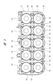
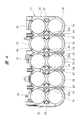
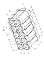
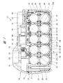
- FIG. 1 It is a perspective view of the electric tool which uses the battery pack of this invention. It is a disassembled perspective view which shows Embodiment 1 of the battery pack of this invention. It is front sectional drawing of the separator and battery cell which are used for the battery pack of FIG. It is front sectional drawing of the separator and battery cell which are used for the battery pack of FIG. It is a perspective view of the separator and battery cell which are used for the battery pack of FIG. It is side surface sectional drawing of the case main body used for the battery pack of FIG. It is front sectional drawing which shows Embodiment 2 of the battery pack of this invention. It is a perspective view of the separator and battery cell which are used for the battery pack of FIG.
- FIG. 14 is an exploded perspective view of the battery pack shown in FIG. 13. It is a perspective view of the case main body used for the battery pack of FIG. It is a top view of the case main body used for the battery pack of FIG. It is front sectional drawing which shows Embodiment 5 of the battery pack of this invention.
- FIG. 1 shows a schematic configuration of the electric tool 10.
- the electric tool 10 includes a tool body 11 and a battery pack 12.
- the battery pack 12 can be attached to and detached from the tool body 11.
- An electric motor 13 is provided in the tool body 11.
- a tip tool 14 is held on the tool body 11, and a power transmission mechanism for transmitting the torque of the electric motor 13 to the tip tool 14 is provided in the tool body 11.
- the tip tool 14 is rotated by the power of the electric motor 13.
- the mounting portion 15 of the tool body 11 can connect the battery pack 12, and a plurality of tool-side terminals 58 are provided on the mounting portion 15.
- a control board is provided in the tool body 11, and the plurality of tool-side terminals 58 are connected to the electric motor 13 via the control board. *
- the battery pack 12 includes a plurality of battery cells 16, separators 17, and a housing case 18.
- the battery cell 16 is a secondary battery that can be repeatedly charged and discharged.
- the battery cell 16 includes a lithium ion battery cell, a nickel metal hydride battery cell, a lithium ion polymer battery cell, a nickel cadmium battery cell, and the like.
- the external appearance of the battery cell 16 is a cylindrical shape, and electrodes are provided at both ends of the battery cell 16 in the length direction. Of the two electrodes, one is a positive electrode and the other is a negative electrode.
- the separator 17 is a holding member that holds the plurality of battery cells 16 in parallel with each other, and the separator 17 has a role as an insulator that covers the plurality of battery cells 16.
- the separator is formed of a synthetic resin that is an insulating material.
- the synthetic resin used here is a thermosetting resin, and includes, for example, an epoxy resin and a vinyl chloride resin. *
- the separator 17 includes a rectangular base portion 19 in plan view, two side portions 20 connected to two parallel sides of the base portion 19 in plan view, and two connection portions 21 that connect the two side portions 20. Have.
- the two side portions 20 are parallel to the front wall 36 and the rear wall 37. Further, four partition walls 22 are provided between the side portions 20 from the base portion 19 toward the connection portion 21. *
- the five battery cells 16 are arranged between the side portion 20 and the partition wall 22 and between the partition walls 22 so that the center lines A1 thereof are parallel to each other.
- the battery cell 16 is accommodated. That is, ten battery cells 16 are arranged in two stages of five.
- the two connecting portions 21 are each formed by connecting five arc portions that are close to the shape of the outer peripheral surface of the battery cell 16.
- An opening 23 is formed between the connecting portions 21.
- the body portions of the five battery cells 16 arranged at positions close to the connection portion 21 are exposed at the openings 23, respectively. *
- the separator 17 has support walls 47 that are respectively continuous with the four partition walls 22.
- the support wall 47 protrudes from the partition wall 22 toward the bottom portion 35.
- the four support walls 47 are parallel to the front wall 36 and the rear wall 37.
- the heat radiating members 24 are respectively attached to the partition wall 22 and the support wall 47.
- a groove 22a is provided across the partition wall 22 and the support wall 47, and the heat dissipation member 24 is fitted into the groove 22a.
- the heat radiating member 24 is integrally formed in a plate shape with a metal having a higher thermal conductivity than synthetic resin, for example, iron or aluminum.
- the heat dissipation member 24 is rectangular.
- the heat radiating member 24 is square or rectangular.
- the side view of the battery pack 12 is that the battery pack 12 is viewed from the side portion 20 side.
- shock absorbing members 25 are respectively attached to the two connecting portions 21.
- the shock absorbing member 25 is provided from one side portion 20 to the other side portion 20 via the connection portion 21.
- the shock absorbing member 25 is integrally formed of a rubber-like elastic body that can be elastically deformed, for example, an elastomer.
- the elastic modulus of the shock absorbing member 25 is higher than that of the separator 17 and the housing case 18.
- the separator 17 is manufactured by molding, and the impact absorbing member 25 is fixed to the surface of the connection portion 21.
- the shock absorbing member 25 is fixed to the separator 17 by integrating the shock absorbing member 25 and the separator 17 by two-layer molding, and the shock absorbing member 25 is fixed to the connecting portion 21 with an adhesive, a double-sided tape or the like. Including methods to do.
- the shock absorbing member 25 is curved in an arc shape along the surface shape of the connecting portion 21.
- the shock absorbing member 25 is formed into a sheet shape or a mat shape, and is solid without bubbles and holes. *
- the elastomer includes a thermoplastic elastomer and a thermosetting synthetic rubber.
- the thermoplastic elastomer includes elastomers such as styrene, olefin, vinyl chloride, urethane, and amide.
- Thermosetting synthetic rubbers include chloroprene rubber, styrene butadiene rubber, isoprene rubber and the like. *
- the first connecting member 26 that connects the electrodes of the four battery cells 16, the second connecting member 27 that connects the electrodes of the four battery cells 16, and the second connecting member 27 that connects the electrodes of the two battery cells 16.
- Three connecting members 28 are provided. Further, on the opposite side of the first connecting member 26 to the third connecting member 28, a fourth connecting member 29 for connecting the electrodes of the four battery cells 16 and a fifth connecting member for connecting the four battery cells 16 are provided.
- a connecting member 30 is provided. *
- the first connection member 26 to the fifth connection member 30 that electrically connect the electrodes of the battery cell 16 are made of a conductive metal material.
- This metal material includes, in addition to copper, aluminum, and the like, a material obtained by performing nickel plating on the surface of a rolled steel sheet.
- a substrate 31 is attached to the outside of the base portion 19 of the separator 17.
- the substrate 31 is made of a nonconductive synthetic resin and has a flat plate shape.
- a plurality of battery side terminals 32 are attached to the substrate 31.
- the plurality of battery side terminals 32 are made of a conductive metal material.
- the plurality of battery-side terminals 32 are respectively connected to the battery cells 16 via lead wires.
- the housing case 18 is an element that houses the separator 17 that holds the plurality of battery cells 16.
- the housing case 18 includes a case main body 33 and a cover 34 that closes the opening of the case main body 33. Both the case main body 33 and the cover 34 are separate bodies formed of non-conductive synthetic resin.
- the synthetic resin used here is a thermosetting resin, and includes, for example, an epoxy resin and a vinyl chloride resin.
- the case main body 33 and the cover 34 are manufactured separately by molding.
- the case main body 33 includes a bottom portion 35, a front wall 36 formed continuously from the outer peripheral edge of the bottom portion 35, a rear wall 37, and two side walls 38.
- the bottom portion 35 is generally rectangular.
- the front wall 36 and the rear wall 37 are connected to two parallel sides of the bottom portion 35.
- the two side walls 38 are connected to two parallel sides of the bottom portion 35.
- the two side walls 38 are substantially parallel to each other.
- a passage 57 is formed between the battery cell 16 and the bottom portion 35 in a state where the separator 17 holding the battery cell 16 is disposed in the housing case 18. Air that has entered the housing case 18 passes through the passage 57.
- the bottom 35 has a larger area than the other front wall 36, rear wall 37, and side wall 38, the contact area between the heat dissipation member 24 and the bottom 35 can be increased. Therefore, the heat dissipation effect when the heat radiating member 24 is brought into contact with the bottom 35 is higher than the heat radiation effect when the heat radiating member 24 is brought into contact with any one of the front wall 36, the rear wall 37, and the side wall 38 other than the bottom 35.
- the front wall 36 is provided with a plurality of vent holes 39 that allow the inside and the outside of the housing case 18 to communicate with each other. That is, the plurality of air holes 39 penetrate the front wall 36 in the thickness direction.
- the plurality of vent holes 39 are passages for discharging the air inside the housing case 18 to the outside.
- the cover 34 has a base portion 40, and a guide rail 42 and a guide groove 43 that are used when the battery pack 12 is attached to the mounting portion 15 of the tool body 11 are provided on the base portion 40.
- the two guide rails 42 are arranged in parallel to each other.
- the mount portion 41 of the cover 34 is provided with a plurality of terminal insertion holes.
- the mount portion 41 is provided with a plurality of ventilation holes that allow the inside and the outside of the housing case 18 to communicate with each other.
- a button 46 is attached to the cover 34.
- the battery pack 12 and the tool main body 11 are brought close to each other, and the battery pack 12 is moved along the guide rail 42 to attach the battery pack 12 to the mounting portion 15 of the tool main body 11.
- the tool side terminal 58 is inserted into the terminal insertion hole of the cover 34, and the tool side terminal 58 and the battery side terminal 32 are connected.
- the battery pack 12 supplies the electric power of the battery cell 16 to the electric motor 13, that is, the battery cell 16 generates heat by discharging. Moreover, when the voltage of the battery pack 12 falls, the battery cell 16 is charged using a charger. Thus, when the battery pack 12 is charged, the battery cell 16 generates heat. The heat of the battery cell 16 is transmitted to the heat radiating member 24 through the separator 17, and the heat of the heat radiating member 24 is transmitted to the bottom portion 35 of the case main body 33. The heat transmitted from the case body 33 is transmitted to the outside air. Therefore, the temperature rise of the battery cell 16 is suppressed, and the temperature of each battery cell 16 can be made uniform. *
- the battery capacity of battery packs has increased from 1.0 Ah, 1.5 Ah, etc. to 2.0 Ah, 2.5 Ah, and the battery pack has a longer charge time and longer discharge time. It is in. For this reason, the maximum temperature of the battery cell tends to increase.
- the battery pack 12 of this embodiment can suppress the temperature rise of the battery cell 16. Therefore, deterioration of the internal member of the battery cell 16 can be suppressed, and a decrease in battery capacity and a decrease in life can be suppressed.
- the life of the battery cell 16 means that the number of times of charging and discharging is reduced.
- the shock absorbing member 25 contacts or closely contacts the inner surface of the case main body 33. For this reason, the impact absorbing member 25 absorbs the impact when the battery pack 12 contacts an object, such as when the battery pack 12 is dropped, and the battery cell 16 can be protected. Further, the shock absorbing member 25 is solid and is not provided with bubbles, holes, or the like. For this reason, a part of the heat transmitted from the battery cell 16 to the separator 17 is transmitted to the separator 17 via the impact absorbing member 25. Therefore, the heat dissipation of the battery cell 16 is improved. *
- Embodiment 2 of the battery pack 12 shown in FIG. 1 will be described with reference to FIGS.
- the cover 34 is provided with a plurality of vent holes 45 and a plurality of terminal insertion holes 44.
- the plurality of battery side terminals 32 are respectively disposed in the terminal insertion holes 44.
- the plurality of vent holes 45 communicate with the inside and the outside of the housing case 18.
- the support wall 47 is formed with a notch 47 a, and the notch 24 a is provided at the end of the heat dissipation member 24.
- the shape of the notch 24a approximates the shape of the notch 47a.
- the charger 48 includes a charging base 49 that supports the battery pack 12, and a ventilation hole 50 is provided in the charging base 49.
- a cooling fan 51 is provided in the charger 48.
- the battery pack 12 can be mounted on the charging stand 49, and the battery cell 16 can be charged.
- the vent hole 45 of the housing case 18 is positioned at a position facing the vent hole 50. Then, when the battery pack 12 is charged by the charger 48, the cooling fan 51 rotates, and the wind formed by the cooling fan 51 enters the accommodation case 18 through the vent hole 45.
- the air flow direction through the passage 57 is basically parallel to the side wall 38. That is, the direction of the air flowing through the passage 57 from the rear wall 37 toward the front wall 36 intersects the center line A1. Further, part of the air that has entered the inside of the storage case 18 passes between the substrate 31 and the cover 34, between the side portion 20 and the front wall 36, and is discharged from the ventilation hole 39 to the outside of the storage case 18. The Therefore, when the battery cell 16 generates heat when the battery pack 12 is charged, the heat of the battery cell 16 is transmitted to the air, and the temperature rise of the battery cell 16 is suppressed.
- the support wall 47 is provided with a notch 47a, and the heat dissipation member 24 is provided with a notch 24a. For this reason, it can suppress that the flow of the air which passes along the channel
- the same effect as that of the first embodiment of the battery pack 12 can be obtained with respect to the same configuration as that of the first embodiment of the battery pack 12. *
- Embodiment 3 of the battery pack 12 will be described with reference to FIGS.
- the same reference numerals as in Embodiment 1 of battery pack 12 or Embodiment 2 of battery pack 12 are the same as in Embodiment 1 or Embodiment 2 of battery pack 12. Is attached.
- a heat dissipation member 24 is attached to the separator 17.
- the battery pack 12 shown in FIG. 11 has a gel-like body 52 provided between the battery cell 16 and the bottom portion 35.
- the gel-like body 52 is a kind of dispersion and is a colloid of a liquid dispersion medium such as sol.
- the gel-like body 52 has a high viscosity due to the dispersoid network and loses fluidity, so that the whole system becomes solid. It is a thing.
- the gel-like body 52 has higher heat dissipation and higher viscosity than the rubber-like elastic body.
- the gel-like body 52 has no bubbles or holes.
- a silicone-based gel can be used as the gel-like body 52. *
- a plurality of gel bodies 52 are provided.
- the plurality of gel bodies 52 are provided between the support walls 47, between the support wall 47 and the front wall 36, and between the support wall 47 and the rear wall.
- One piece is arranged between each wall 37.
- two ribs 35a parallel to the side wall 38 are provided on the bottom 35, and the five gel bodies 52 are arranged with a gap between the two ribs 35a. That is, the five gel bodies 52 are arranged along the air flow direction through the passage 57 formed between the battery cell 16 and the bottom portion 35.
- a part of the support wall 47 and the heat radiating member 24 are disposed between the gel-like bodies 52.
- the five gel bodies 52 are in close contact with the surface of the battery cell 16 and the inner surface of the case main body 33. *
- the same constituent parts as those of the first embodiment of the battery pack 12 or the second embodiment of the battery pack 12 are described in the first embodiment of the battery pack 12 or the implementation of the battery pack 12.
- the same effect as that of Form 2 can be obtained.
- the heat of the battery cell 16 is transmitted to the case body 33 via the gel body 52. Therefore, the heat dissipation of the battery cell 16 is further improved.
- the gel-like body 52 also functions as a buffer member that absorbs or relaxes the impact applied to the battery cell 16. *
- Embodiment 4 of the battery pack 12 will be described with reference to FIGS.
- the same reference numerals as those in the first to third embodiments of the battery pack 12 are assigned to the same configurations as those of the first to third embodiments of the battery pack 12.
- the impact absorbing member 25 and the heat radiating member 24 are not attached to the separator 17. Further, the support wall 47 is not provided in the separator 17.
- a heat dissipation member 53 is provided between the separator 17 and the bottom 35 of the case body 33. That is, the heat dissipation member 53 is provided in the passage 57 formed between the battery cell 16 and the bottom portion 35.
- the heat radiating member 53 is integrally formed of the same material as the shock absorbing member 25, and the heat radiating member 53 is fixed to the case body 33.
- the method of fixing the heat radiating member 53 to the case main body 33 is a method of integrating the case main body 33 and the heat radiating member 53 by two-layer molding, and fixing the heat radiating member 53 to the surface of the bottom portion 35 with an adhesive, a double-sided tape, or the like Including methods to do. *
- the heat dissipating members 53 are provided in two rows along the two side walls 38, and the heat dissipating members 53 are in close contact with the bottom 35.
- the two heat radiating members 53 are arranged at intervals so as to intersect the flow direction of the air flowing through the passage 57.
- the heat dissipating member 53 is disposed at a position corresponding to the connecting portion 21 of the separator 17, and a plurality of arc-shaped concave portions 53 a are formed on the surface of the heat dissipating member 53 that contacts the connecting portion 21.
- the plurality of recesses 53 a are in close contact with the connection portion 21.
- an insulating member 56 is provided between the ten battery cells 16 and the side wall 38. *
- the heat of the battery cell 16 is improved because the heat of the battery cell 16 is transmitted to the case body 33 via the separator 17 and the heat dissipation member 53.
- the air generated by the cooling fan 51 enters the housing case 18 through the vent holes 45. enter in. Then, air flows through the passage 57 between the battery cell 16 and the bottom portion 35 of the case main body 33, heat of the battery cell 16 is transmitted to the air, and the temperature rise of the battery cell 16 is suppressed.
- the battery pack 12 collides with an object, the impact is absorbed by the heat radiating member 53 and the battery cell 16 can be protected. Further, in the fourth embodiment of the battery pack 12, the same effects as in the first to third embodiments of the battery pack 12 can be obtained with respect to the same configuration as that of the first to third embodiments of the battery pack 12. *
- the battery pack 12 according to the fifth embodiment differs from the case main body 33 according to the fourth embodiment of the battery pack 12 in that the heat radiating member 54 is attached to the case main body 33.
- the case main body 33 is provided with a heat radiating member 54 between two heat radiating members 53. That is, the heat radiating member 53 and the heat radiating member 54 are arranged at intervals in a direction intersecting the flow direction of the air flowing through the passage 57.
- the heat dissipating member 54 is made of the same material as the heat dissipating member 53, and the heat dissipating member 54 is fixed to the bottom portion 35 like the heat dissipating member 53.
- the heat dissipating member 54 includes a plurality of recesses 54a at intervals in the length direction.
- the plurality of recesses 54 a are circular arc surfaces having the same curvature as the outer peripheral shape of the battery cell 16.
- the plurality of heat radiating members 54 are arranged in parallel with the heat radiating member 53 when the case main body 33 is viewed in plan.
- the thickness of the heat radiating member 54 is larger than the thickness of the heat radiating member 53.
- the other configuration of the battery pack 12 in the fifth embodiment is the same as the other configuration of the battery pack 12 in the fourth embodiment, and the other effects of the battery pack 12 in the fifth embodiment are as follows. This is the same as the other effects in the fourth embodiment. *
- the case main body 33 according to the fourth embodiment of the battery pack 12 is that a plurality of heat radiation members 53 attached to the case main body 33 are provided along the longitudinal direction of the side wall 38. Is different.
- Four heat radiating members 53 are arranged at intervals along one side wall 38, and four heat radiating members 53 are arranged at intervals along the other side wall 38. That is, the plurality of heat dissipating members 53 are arranged at intervals along the flow direction of the air flowing through the passage 57. Further, the two heat radiating members 53 are arranged at intervals in a direction intersecting with the air flow direction passing through the passage 57. All the heat radiating members 53 have two recesses 53a. When the separator 17 holding the battery cell 16 is accommodated in the case main body 33, the heat dissipation member 53 comes into contact with the connection portion 21. *
- the air generated by the cooling fan 51 enters the housing case 18 through the vent hole 45. Then, air flows between the battery cell 16 and the bottom 35 of the case main body 33, heat of the battery cell 16 is transmitted to the air, and a temperature rise of the battery cell 16 is suppressed. Furthermore, part of the air passing between the battery cell 16 and the bottom 35 flows in parallel with the rear wall 37 in a plan view of the case body 33 and enters between the heat dissipation members 53. Therefore, the heat transmitted to the connection part 21 is transmitted to the air, and the heat dissipation of the battery cell 16 is improved.
- the other configuration of the battery pack 12 in the sixth embodiment is the same as the other configuration of the battery pack 12 in the fourth embodiment, and the effect of the battery pack 12 in the sixth embodiment is the same as that of the battery pack 12. This is the same as the effect of Form 4. *
- Embodiment 7 of the battery pack 12 will be described with reference to FIGS.
- the battery pack 12 according to the seventh embodiment differs from the case main body 33 according to the sixth embodiment of the battery pack 12 in that the heat dissipating member 55 attached to the case main body 33 is provided between the heat dissipating members 53.
- a plurality, specifically four, of the heat radiating members 55 are provided between the front wall 36 and the rear wall 37.
- the heat radiating members 53 and 55 are arranged at intervals in a direction intersecting the flow direction of the air flowing through the passage 57. That is, the heat radiation members 53 and 55 are arranged in three rows in total.
- the four heat radiating members 55 are arranged at intervals along the flow direction of the air flowing through the passage 57. *
- the heat radiating member 55 is made of the same material as the heat radiating member 53, and the heat radiating member 55 is fixed to the bottom portion 35 of the case body 33 in the same manner as the heat radiating member 53.
- Four heat radiating members 55 are arranged at intervals, and all the heat radiating members 55 have two arc-shaped concave portions 55a.
- the other configuration of the battery pack 12 in the seventh embodiment is the same as the other configuration of the battery pack 12 in the sixth embodiment, and the effect of the battery pack 12 in the seventh embodiment is the same as that of the battery pack 12. This is the same as the effect of Form 6.
- Embodiment 8 of the battery pack 12 will be described with reference to FIGS.
- the same reference numerals as those of the first and second embodiments of the battery pack 12 are assigned to the same configurations as those of the first and second embodiments of the battery pack 12.
- one gel-like body 52 is provided in a passage 57 formed between the battery cell 16 and the bottom portion 35.
- Two ribs 35 a are provided on the bottom 35, and the two ribs 35 a are parallel to the side wall 38.
- the gel-like body 52 is disposed between the two ribs 35a.
- the gel-like body 52 is arranged in a long shape along the flow direction of the air flowing through the passage 57. *
- the gel-like body 52 is in contact with the surface of the battery cell 16 and is in contact with the inner surface of the bottom portion 35. If the battery cell 16 is not in contact with the gel-like body 52, the surface is flat as shown in FIG. 25. When the battery cell 16 comes into contact with the gel-like body 52, the surface becomes an arc shape, and the gel-like body 52 is in close contact with the battery cell 16. . In the battery pack 12, the support wall 47 and the heat radiating member 24 are not attached to the separator 17. *
- the heat dissipating material in the present invention includes heat dissipating members 24, 53, 54, 55, a gel-like body 52, and an impact absorbing member 25, and the tool main body 11 corresponds to the apparatus main body of the present invention.
- the battery pack of the present invention is not limited to the above-described embodiment, and various modifications can be made without departing from the gist thereof.
- the battery pack of the present invention includes a structure that accommodates less than 10 battery cells or a structure that accommodates 11 or more battery cells.
- the battery pack includes one in which three or more battery cells are stacked and held by a separator.
- the heat dissipation member described in the first embodiment is arranged between the battery cells stacked in three stages.
- the separator includes an integral type and a structure divided into a plurality.
- the structure of the heat radiator in the present invention is different from the structure of the sponge.
- a sponge is a porous body, and air and an air layer exist in the sponge.
- a heat radiator is a solid body without a bubble, a hole, etc., air and an air layer do not exist. That is, the heat conductivity of the radiator in the present invention is higher than the heat conductivity of the sponge.
- the surface shape of the gel-like body described in each embodiment may be in a state where the battery cell is not in contact, or may be either a flat surface or an arc surface. That is, the gel-like body may be adhered to the surface of the battery cell in a state where the battery cell is in contact.
- the battery pack of the present invention includes one in which the heat transfer material is fixed to the case body or the separator, and one in which the heat transfer material is not fixed to either the case body or the separator.
- the battery pack of the present invention includes one in which the housing case can be attached to and detached from the device main body, and one in which the housing case is fixed to the device main body and cannot be detached. *
- the electric tool in which the battery pack of the present invention is used includes a grinder, a sander, a nailing machine, a screw driving machine, a tacker, a dust collector, a blower, a pump, a high-pressure washing machine, a chain saw, a gardening tool, a cultivator, and the like. That is, the electric tool of the present invention includes a device that rotates the electric motor with the electric power of the battery pack and converts the rotational motion into at least one of the reciprocating motion and the rotational motion of the operating member.
Landscapes
- Chemical & Material Sciences (AREA)
- Chemical Kinetics & Catalysis (AREA)
- Electrochemistry (AREA)
- General Chemical & Material Sciences (AREA)
- Engineering & Computer Science (AREA)
- Manufacturing & Machinery (AREA)
- Life Sciences & Earth Sciences (AREA)
- Biophysics (AREA)
- Secondary Cells (AREA)
- Battery Mounting, Suspending (AREA)
Abstract
収容ケース内に配置された電池セルの温度が上昇することを抑制できる電池パックを提供する。複数の電池セル16を保持したセパレータ17を収容ケース18内に配置した電池パック12であって、収容ケース18は、ケース本体33及びカバー34を備え、セパレータ17に、電池セル16同士の間に位置する溝が設けられ、放熱部材24が溝に嵌め込まれており、電池セル16の熱が、セパレータ17及び放熱部材24を経由してケース本体33の底部35に伝達される構造。
Description
本発明は、電池パック及び電動工具及び充電器に関する。
従来、電動工具に用いられる電池パックが知られており、その電池パックの一例が特許文献1に記載されている。特許文献1に記載された電池パックは、電動工具のハンドルに着脱される。電池パックは、保持部材としてのセパレータにより保持された複数の電池セルと、セパレータ及び電池セルを収容する収容ケースとを有する。収容ケースは、ケース本体と、ケース本体の開口部を塞ぐカバーとを有する。また、収容ケース内に基板が設けられており、基板に電池側端子が取り付けられている。電池側端子は電池セルの電極に接続されている。さらに、カバーに複数の端子挿入孔が設けられており、複数の電池側端子は、端子挿入孔にそれぞれ配置されている。
一方、電動工具の本体部に電動モータが設けられており、本体部のグリップに機器側端子が設けられている。機器側端子は、制御回路を介して電動モータに接続される。本体部は、先端工具としてのドリルビットを保持しており、電動モータとドリルビットとが動力伝達可能に接続されている。
そして、電池パックがグリップに装着されると、機器側端子と電池側端子とが接続される。さらに、作業者が、グリップに設けられているトリガを操作すると、電池パックの電力が電動モータに供給され、電動モータのトルクがドリルビットに伝達される。
ところで、電池セルの電力を電動モータに供給する放電時には、電池セルが発熱する。また、電池パックを充電器に装着し、電池セルに充電を行う際にも、電池セルが発熱する。しかしながら、電池セルを保持するセパレータは、絶縁性の材料である合成樹脂で形成されているため熱伝導性が低く、電池セルの温度が上昇する問題があった。
本発明の目的は、電池セルの放熱性を向上した電池パック及び電動工具及び充電器を提供することにある。
一実施形態の電池パックは、電池セルを保持した保持部材を収容ケース内に配置した電池パックであって、前記収容ケース内に設けられ、かつ、前記電池セルの熱を前記収容ケースに伝達する放熱体を備えている。
他の実施形態の電池パックは、電池セルを保持した保持部材を内部に収容した収容ケースを有する電池パックであって、前記電池セルと前記収容ケースとの間に形成され、かつ、前記収容ケース内に進入した空気が流れる通路と、前記通路に配置され、前記電池セルの熱を放熱する放熱体と、を備えている。
他の実施形態の電動工具は、機器本体と、前記機器本体に収容されるモータと、を有し、前記機器本体は、前記電池パックが接続可能である。
他の実施形態の充電器は、前記電池パックを支持することが可能な充電台を備え、かつ、前記充電台に支持された前記電池パックに充電可能である。
本発明の電池パックによれば、電池セルの熱を収容ケースに伝達して、電池セルの放熱性を向上できる。
本発明の電池パックを用いる電動工具の実施形態について、図面を用いて詳細に説明する。図1は電動工具10の概略構成を示す。電動工具10は、工具本体11及び電池パック12を有している。電池パック12は、工具本体11に取り付け及び取り外し可能である。工具本体11内に電動モータ13が設けられている。工具本体11に先端工具14が保持されており、電動モータ13のトルクを先端工具14に伝達する動力伝達機構が、工具本体11内に設けられている。先端工具14は電動モータ13の動力で回転する。工具本体11の装着部15は、電池パック12を接続することが可能であり、複数の工具側端子58が装着部15に設けられている。制御基板が工具本体11内に設けられており、複数の工具側端子58は、制御基板を介して電動モータ13に接続されている。
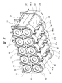
(実施の形態1) 電池パック12の実施の形態1を、図2~図6を参照して説明する。電池パック12は、複数の電池セル16及びセパレータ17及び収容ケース18を有する。電池セル16は、充電及び放電を繰り返し行うことのできる二次電池である。電池セル16は、リチウムイオン電池セル、ニッケル水素電池セル、リチウムイオンポリマー電池セル、ニッケルカドミウム電池セル等を含む。電池セル16は外観が円柱形状であり、電池セル16の長さ方向の両端部に電極がそれぞれ設けられている。2つの電極のうち、一方は正極であり他方は負極である。
セパレータ17は、複数の電池セル16を相互に平行に保持する保持部材であり、セパレータ17は、複数の電池セル16を覆うインシュレータとしての役割を備えている。セパレータは、絶縁性の材料である合成樹脂により成形されている。ここで用いられる合成樹脂は、熱硬化性樹脂であり、例えば、エポキシ樹脂、塩化ビニル樹脂を含む。
セパレータ17は、平面視で四角形の基部19と、平面視で基部19の平行な2辺に連続された2つの側部20と、2つの側部20を接続する2つの接続部21と、を有する。2つの側部20は、前壁36及び後壁37と平行である。また、側部20同士の間に、基部19から接続部21に向けて4つの仕切り壁22が設けられている。
そして、側部20と仕切り壁22との間、仕切り壁22同士の間に、5本の電池セル16を、その中心線A1が互いに平行となるように並べて1列とし、2列で10本の電池セル16を収容している。つまり、10本の電池セル16が、5本ずつ2段に並べられている。2つの接続部21は、電池セル16の外周面の形状に近する円弧部を、それぞれ5つ連続したものである。接続部21同士の間に開口部23が形成されている。2列に並べた10本の電池セル16のうち、接続部21に近い位置に並べた5本の電池セル16の胴部は、開口部23にそれぞれ露出している。
さらに、セパレータ17は、4つの仕切り壁22にそれぞれ連続した支持壁47を有する。支持壁47は、仕切り壁22から底部35に向けて突出している。4つの支持壁47は、前壁36及び後壁37と平行である。仕切り壁22及び支持壁47に亘り、放熱部材24がそれぞれ取り付けられている。仕切り壁22及び支持壁47に亘る溝22aが設けられており、放熱部材24は溝22aに嵌め込まれている。放熱部材24は、合成樹脂よりも熱伝導率が高い金属、例えば、鉄、アルミニウムでプレート形状に一体成形されている。電池パック12を側面視すると、放熱部材24は四角形である。具体的には、放熱部材24は、正方形または長方形である。電池パック12の側面視は、電池パック12を側部20側から視ることである。
さらに、2つの接続部21に衝撃吸収部材25がそれぞれ取り付けられている。衝撃吸収部材25は、一方の側部20から接続部21を介して他方の側部20に亘ってそれぞれ設けられている。衝撃吸収部材25は、弾性変形可能なゴム状弾性体、例えば、エラストマーにより一体成形されている。衝撃吸収部材25の弾性係数は、セパレータ17及び収容ケース18の弾性係数よりも高い。
セパレータ17はモールド成形で製造されており、衝撃吸収部材25が接続部21の表面に固定されている。衝撃吸収部材25をセパレータ17に固定する方法は、衝撃吸収部材25とセパレータ17とを2層成形により一体化する方法、衝撃吸収部材25を接続部21に対して接着剤、両面テープ等により固定する方法を含む。衝撃吸収部材25は、接続部21の表面形状に沿って円弧状に湾曲している。衝撃吸収部材25は、シート状、またはマット状に成形されており、気泡、孔が無く中実である。
エラストマーは、熱可塑性エラストマー、熱硬化性の合成ゴムを含む。熱可塑性エラストマーは、スチレン系、オレフィン系、塩ビ系、ウレタン系、アミド系等のエラストマーを含む。熱硬化性の合成ゴムは、クロロプレンゴム、スチレンブタジェンゴム、イソプレンゴム等を含む。
また、4本の電池セル16の電極を接続する第1の接続部材26、4本の電池セル16の電極を接続する第2の接続部材27、2本の電池セル16の電極を接続する第3の接続部材28が設けられている。さらに、第1の接続部材26~第3の接続部材28の反対側に、4本の電池セル16の電極を接続する第4の接続部材29、4本の電池セル16を接続する第5の接続部材30が設けられている。
本実施形態において、電池セル16の電極同士を電気的に接続する第1の接続部材26~第5の接続部材30は、導電性を有する金属材料により構成されている。この金属材料は、銅、アルミニウム等の他、圧延鋼板の表面にニッケルメッキが施された材料を含む。
さらに、セパレータ17の基部19の外側には基板31が取り付けられている。基板31は、非導電性の合成樹脂で平板形状に構成されている。基板31には、複数の電池側端子32が取り付けられている。複数の電池側端子32は導電性の金属材料により構成されている。複数の電池側端子32は、リード線を介して電池セル16にそれぞれ接続されている。
収容ケース18は、複数の電池セル16を保持したセパレータ17を収容する要素である。収容ケース18は、ケース本体33と、ケース本体33の開口部を塞ぐカバー34と、を有する。ケース本体33及びカバー34は、共に非導電性の合成樹脂により成形された別体である。ここで用いられる合成樹脂は、熱硬化性樹脂であり、例えば、エポキシ樹脂、塩化ビニル樹脂を含む。ケース本体33及びカバー34は、モールド成形により別体で製造されている。
前記ケース本体33は、底部35と、底部35の外周縁に連続して形成された前壁36と、後壁37と、2枚の側壁38とを有する。ケース本体33を平面視すると、底部35は概ね四角形である。前壁36及び後壁37は、底部35における平行な2辺に接続されている。また、2枚の側壁38は底部35における平行な2辺に接続されている。2枚の側壁38は相互に略平行である。電池セル16を保持したセパレータ17が収容ケース18内に配置された状態で、電池セル16と底部35との間に通路57が形成される。通路57は、収容ケース18内に進入した空気が通る。
4枚の放熱部材24のうち、溝22aから露出している1辺は、セパレータ17が収容ケース18内に収容された状態で、底部35の表面に接触する。底部35は他の前壁36、後壁37、側壁38と比較して面積が大きいため、放熱部材24と底部35との接触面積を大きくすることができる。したがって、放熱部材24を底部35に接触させる場合の放熱効果は、放熱部材24を、底部35以外の前壁36、後壁37、側壁38のいずれかに接触させる場合の放熱効果よりも高い。
さらに、前壁36には、収容ケース18の内部と外部とを連通する複数の通気孔39が設けられている。すなわち、複数の通気孔39は、前壁36を厚さ方向に貫通している。複数の通気孔39は、収容ケース18の内部の空気を外部に排出する通路である。
一方、カバー34は基部40を有しており、基部40には、電池パック12を工具本体11の装着部15に取り付けるときに用いられるガイドレール42及びガイド溝43が、それぞれ設けられている。2つのガイドレール42は相互に平行に配置されている。カバー34のマウント部41には、複数の端子挿入孔が設けられている。ケース本体33にカバー34を被せると、複数の電池側端子32が複数の端子挿入孔内に配置される。さらにまた、マウント部41には、収容ケース18の内部と外部とを連通する複数の通気孔が設けられている。さらに、カバー34にボタン46が取り付けられている。
次に、電池パック12を工具本体11の装着部15に取り付ける作業を説明する。図1のように、電池パック12と工具本体11とを近づけるとともに、ガイドレール42に沿って電池パック12を移動させて、工具本体11の装着部15に電池パック12を取り付ける。電池パック12を装着部15に取り付ける途中で、工具側端子58がカバー34の端子挿入孔に差し込まれ、工具側端子58と電池側端子32とが接続される。
電池パック12を装着部15に取り付けた状態で、トリガ11aが操作されて電池パック12の電力が電動モータ13に供給されて、電動モータ13の出力軸が回転すると、その電動モータ13の動力が先端工具14に伝達される。電池パック12が装着部15に取り付けられている状態で、ボタン46を作業者が操作して、電池パック12を装着部15から取り外すことができる。
電池パック12は、電池セル16の電力を電動モータ13に供給する際に、つまり、放電により電池セル16が発熱する。また、電池パック12の電圧が低下すると、充電器を用いて電池セル16に充電する。このように、電池パック12に充電を行う際にも、電池セル16が発熱する。電池セル16の熱は、セパレータ17を介して放熱部材24に伝達され、放熱部材24の熱はケース本体33の底部35に伝達される。ケース本体33の伝達された熱は、外気に伝達される。したがって、電池セル16の温度上昇が抑制され、各電池セル16の温度を均一化することができる。
近年、電池パックの電池容量は、1.0Ahや1.5Ah等から、2.0Ahや2.5Ahへの高容量化が進み、電池パックへの充電時間が長くなり、放電時間が長くなる傾向にある。このため、電池セルの最高温度が上昇する傾向にある。これに対して、本実施形態の電池パック12は、電池セル16の温度上昇を抑制できる。したがって、電池セル16の内部部材の劣化を抑制でき、電池セル16電池容量の低下及び寿命の低下を抑制できる。電池セル16の寿命は、充電放電の回数が少なくなることを意味する。
また、電池セル16を保持するセパレータ17が、収容ケース18に収容されると、衝撃吸収部材25が、ケース本体33の内面に接触または密着する。このため、電池パック12が落下した場合等のように、電池パック12が物体に接触した際の衝撃を、衝撃吸収部材25が吸収し、電池セル16を保護することができる。さらに、衝撃吸収部材25は、中実であり、気泡、孔等が設けられていない。このため、電池セル16からセパレータ17に伝達された熱の一部は、衝撃吸収部材25を介してセパレータ17に伝達される。したがって、電池セル16の放熱性が向上する。
(実施の形態2) 次に、図1に示す電池パック12の実施の形態2を、図7~図10を参照して説明する。図7~図10に示す要素において、図1~図6に示す要素と同じ要素については、図1~図6と同じ符号を付してある。カバー34に複数の通気孔45及び複数の端子挿入孔44が設けられている。複数の電池側端子32は、端子挿入孔44にそれぞれ配置されている。複数の通気孔45は、収容ケース18の内部及び外部に通じている。
また、支持壁47には切り欠き部47aが形成されており、放熱部材24の端部に切り欠き部24aが設けられている。切り欠き部24aの形状は、切り欠き部47aの形状と近似する。
一方、工具本体11から取り外した電池パック12に充電可能な充電器が、図10に示されている。充電器48は、電池パック12を支持する充電台49を備え、通気孔50が充電台49に設けられている。また、冷却ファン51が充電器48内に設けられている。そして、電池パック12を充電台49に載せて、電池セル16に充電することができる。電池パック12が充電台49で支持されると、通気孔50と対向した位置に、収容ケース18の通気孔45が位置することになる。そして、充電器48により電池パック12に充電する際に冷却ファン51が回転し、冷却ファン51により形成された風は、通気孔45を経由して収容ケース18内に進入する。
収容ケース18内に進入した空気の一部は、側部20と後壁37との間、通路57を通り、通気孔39から収容ケース18の外部に排出される。電池パック12の平面視で、通路57を通る空気の流れ方向は、基本的には側壁38と平行な方向である。つまり、通路57を後壁37から前壁36に向けて流れる空気の方向は、中心線A1と交差する。また、収容ケース18の内部に進入した空気の一部は、基板31とカバー34との間、側部20と前壁36との間を通り、通気孔39から収容ケース18の外部に排出される。したがって、電池パック12に充電する際に電池セル16が発熱すると、電池セル16の熱は空気に伝達され、電池セル16の温度上昇が抑制される。
本実施形態では、支持壁47に切り欠き部47aが設けられ、放熱部材24に切り欠き部24aが設けられている。このため、通路57を通る空気の流れが妨げられることを抑制でき、電池セル16の冷却性能の低下を防止できる。電池パック12の実施の形態2において、電池パック12の実施の形態1と同じ構成については、電池パック12の実施の形態1と同じ効果を得ることができる。
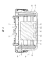
(実施の形態3) 電池パック12の実施の形態3を図11、図12を参照して説明する。電池パック12の実施の形態3において、電池パック12の実施の形態1または実施の形態2と同じ構成については、電池パック12の実施の形態1または、電池パック12の実施の形態2と同じ符号を付してある。図11の電池パック12は、セパレータ17に放熱部材24が取り付けられている。また、図11に示す電池パック12は、電池セル16と底部35との間に設けたゲル状体52を有する。ゲル状体52は、分散系の一種で、ゾルのような液体分散媒のコロイドであるが、分散質のネットワークにより高い粘性を持ち、かつ、流動性を失い、系全体としては固体状になったものである。ゲル状体52は、ゴム状弾性体に比べて放熱性が高く、かつ、粘性が強い。ゲル状体52は気泡、孔が無い。ゲル状体52としては、例えば、シリコーン系ゲルを用いることができる。
ゲル状体52は、複数、具体的には5個設けられており、複数のゲル状体52は、支持壁47同士の間、支持壁47と前壁36との間、支持壁47と後壁37との間に、それぞれ1個ずつ配置されている。また、側壁38と平行なリブ35aが、底部35に2本設けられており、5個のゲル状体52は、2本のリブ35aの間に間隔をおいて配置されている。つまり、5個のゲル状体52は、電池セル16と底部35と間に形成される通路57を通る空気の流れ方向に沿って配置されている。そして、ゲル状体52同士の間に、支持壁47及び放熱部材24の一部が配置されている。電池セル16を保持したセパレータ17がケース本体33内に収容された状態で、5個のゲル状体52は、電池セル16の表面及びケース本体33の内面に密着する。
電池パック12の実施の形態3において、電池パック12の実施の形態1、または電池パック12の実施の形態2と同じ構成部位については、電池パック12の実施の形態1、または電池パック12の実施の形態2と同じ効果を得ることができる。また、電池パック12の実施の形態3においては、電池セル16の熱がゲル状体52を経由してケース本体33に伝達される。したがって、電池セル16の放熱性が一層向上する。さらに、ゲル状体52は、電池セル16に加わる衝撃を吸収または緩和する緩衝部材としても機能する。
(実施の形態4) 電池パック12の実施の形態4を図13~図16を参照して説明する。電池パック12の実施の形態4において、電池パック12の実施の形態1~3と同じ構成については、電池パック12の実施の形態1~3と同じ符号を付してある。図13の電池パック12は、セパレータ17に衝撃吸収部材25及び放熱部材24が取り付けられていない。また、セパレータ17に支持壁47は設けられていない。
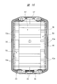
図13に示す電池パック12は、セパレータ17と、ケース本体33の底部35との間に、放熱部材53が設けられている。つまり、電池セル16と底部35との間に形成される通路57に、放熱部材53が設けられている。放熱部材53は、衝撃吸収部材25と同じ材質で一体成形されており、放熱部材53は、ケース本体33に固定されている。放熱部材53をケース本体33に固定する方法は、ケース本体33と放熱部材53とを、2層成形により一体化する方法、放熱部材53を、底部35の表面に接着剤、両面テープ等により固定する方法を含む。
放熱部材53は、2つの側壁38に沿って2列で設けられており、放熱部材53は底部35に密着されている。2つの放熱部材53は、通路57を流れる空気の流れ方向に対して交差するに間隔をおいて配置されている。また、放熱部材53は、セパレータ17の接続部21に対応する位置に配置されており、放熱部材53において接続部21に接触する表面に、円弧状の凹部53aが複数形成されている。電池セル16を保持したセパレータ17がケース本体33に収容されると、複数の凹部53aは、接続部21にそれぞれ密着する。なお、電池パック12の実施の形態4においては、10本の電池セル16と側壁38との間に、絶縁部材56が設けられている。
電池パック12の実施の形態4は、電池セル16の熱が、セパレータ17及び放熱部材53を経由してケース本体33に伝達されるため、電池セル16の放熱性が向上する。また、組み立てられた電池パック12を図10のように充電器48の充電台49に載せ、電池パック12に充電すると、冷却ファン51により生じた空気が通気孔45を介して収容ケース18内に進入する。すると、電池セル16とケース本体33の底部35との間の通路57を空気が流れて、電池セル16の熱が空気に伝達され、電池セル16の温度上昇が抑制される。
さらに、電池パック12が物体に衝突すると、その衝撃が放熱部材53により吸収され、電池セル16を保護できる。さらに、電池パック12の実施の形態4において、電池パック12の実施の形態1~3と同じ構成については、電池パック12の実施の形態1~3と同じ効果を得られる。
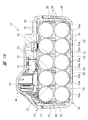
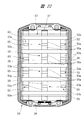
(実施の形態5) 電池パック12の実施の形態5を、図17及び18を参照して説明する。電池パック12の実施の形態5は、ケース本体33に放熱部材54を取り付けた点が、電池パック12の実施の形態4のケース本体33と相違する。具体的に説明すると、ケース本体33は、2個の放熱部材53の間に、放熱部材54が設けられている。つまり、放熱部材53と放熱部材54とが、通路57を流れる空気の流れ方向に対して交差する方向に間隔をおいて配置されている。放熱部材54は放熱部材53と同じ材質であり、放熱部材54は、放熱部材53と同様に底部35に固定されている。放熱部材54は、長さ方向に間隔をおいて複数の凹部54aを備えている。複数の凹部54aは、電池セル16の外周形状と同じ曲率の円弧面である。複数の放熱部材54は、ケース本体33を平面視すると放熱部材53と平行に配置されている。放熱部材54厚さは、放熱部材53の厚さよりも大きい。
電池パック12の実施の形態5においては、電池セル16を保持したセパレータ17がケース本体33に収容されると、放熱部材53はセパレータ17の接続部21に接触し、放熱部材54は電池セル16の表面に接触する。このため、電池セル16の熱は、セパレータ17及び放熱部材53を介してケース本体33に伝達され、かつ、電池セル16の熱は、放熱部材54を介してケース本体33に伝達される。
つまり、電池セル16の熱をケース本体33に伝達する経路が、並列に2系統設けられており、電池セル16の放熱性が向上する。また、電池パック12を図10のように充電器48の充電台49に載せ、電池パック12に充電すると、冷却ファン51により生じた空気が通気孔45を介して収容ケース18内に進入する。すると、電池セル16と底部35との間に形成される通路57を空気が流れて、電池セル16の熱が空気に伝達され、電池セル16の温度上昇が抑制される。
なお、電池パック12の実施の形態5における他の構成は、電池パック12の実施の形態4における他の構成と同じであり、電池パック12の実施の形態5における他の効果は、電池パック12の実施の形態4における他の効果と同じである。
(実施の形態6) 電池パック12の実施の形態6を、図19及び20を参照して説明する。電池パック12の実施の形態6は、ケース本体33に取り付けられた放熱部材53が、側壁38の長手方向に沿って複数設けられている点が、電池パック12の実施の形態4のケース本体33と相違する。一方の側壁38に沿って4個の放熱部材53が間隔をおいて配置され、他方の側壁38に沿って4個の放熱部材53が間隔をおいて配置されている。つまり、複数の放熱部材53は、通路57を流れる空気の流れ方向に沿って間隔をおいて配置されている。また、2個の放熱部材53は、通路57を通る空気の流れ方向に交差する方向に、間隔をおいて配置されている。全ての放熱部材53は、凹部53aを2つ有する。電池セル16を保持したセパレータ17がケース本体33に収容されると、放熱部材53は接続部21に接触する。
また、電池パック12を図10の充電器48の充電台49に載せ、電池パック12に充電すると、冷却ファン51により生じた空気が通気孔45を介して収容ケース18内に進入する。すると、電池セル16とケース本体33の底部35との間を空気が流れて、電池セル16の熱が空気に伝達され、電池セル16の温度上昇が抑制される。さらに、電池セル16と底部35との間を通る空気の一部は、ケース本体33の平面視で後壁37と平行に流れ、放熱部材53同士の間に進入する。したがって、接続部21に伝達された熱が空気に伝達され、電池セル16の放熱性が向上する。
なお、電池パック12の実施の形態6における他の構成は、電池パック12の実施の形態4における他の構成と同じであり、電池パック12の実施の形態6の効果は、電池パック12の実施の形態4の効果と同じである。
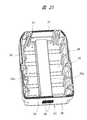
(実施の形態7) 電池パック12の実施の形態7を、図21及び22を参照して説明する。電池パック12の実施の形態7は、ケース本体33に取り付けられた放熱部材55が、放熱部材53同士の間に設けられている点が、電池パック12の実施の形態6のケース本体33と相違する。放熱部材55は、前壁36と後壁37との間に複数、具体的には4個設けられている。放熱部材53,55は、通路57を流れる空気の流れ方向に対して交差する方向に、間隔をおいて配置されている。つまり、放熱部材53,55は、全部で3列配置されている。4個の放熱部材55は、通路57を流れる空気の流れ方向に沿って間隔をおいて配置されている。
放熱部材55は、放熱部材53と同じ材質であり、放熱部材55は、放熱部材53と同様にケース本体33の底部35に固定されている。4個の放熱部材55が間隔をおいて配置されており、全ての放熱部材55は、円弧状の凹部55aを2つ有する。電池セル16を保持したセパレータ17がケース本体33に収容されると、放熱部材55は電池セル16の外周面に接触する。したがって、電池セル16からセパレータ17に伝達された熱は、放熱部材53を介してケース本体33に伝達される。また、電池セル16の熱は、放熱部材55を介してケース本体33に伝達される。したがって、電池セル16の放熱性が向上する。
また、電池パック12を図10のように充電器48の充電台49に載せ、電池パック12に充電すると、冷却ファン51により生じた空気が通気孔45を介して収容ケース18内に進入する。すると、通路57を空気が流れて電池セル16の熱が空気に伝達され、電池セル16の温度上昇が抑制される。さらに、通路57を通る空気の一部は、ケース本体33の平面視で後壁37と平行に流れ、放熱部材53同士の間に進入し、かつ、放熱部材55同士の間に進入する。したがって、接続部21に伝達された熱が空気に伝達され、かつ、電池セル16の熱が直接空気に伝達され、電池セル16の放熱性が向上する。
なお、電池パック12の実施の形態7における他の構成は、電池パック12の実施の形態6における他の構成と同じであり、電池パック12の実施の形態7の効果は、電池パック12の実施の形態6の効果と同じである。
(実施の形態8) 電池パック12の実施の形態8を図23~図25を参照して説明する。電池パック12の実施の形態8において、電池パック12の実施の形態1、2と同じ構成については、電池パック12の実施の形態1、2と同じ符号を付してある。電池パック12は、電池セル16と底部35との間に形成される通路57に、ゲル状体52が1個設けられている。底部35に2本のリブ35aが設けられており、2本のリブ35aは側壁38と平行である。ゲル状体52は2本のリブ35aの間に配置されている。ゲル状体52は、通路57を流れる空気の流れ方向に沿って長尺状に配置されている。
ゲル状体52は、電池セル16の表面に接触し、かつ、底部35の内面に接触している。ゲル状体52は、電池セル16が接触していなければ、図25のように表面が平坦であり、電池セル16が接触すると表面が円弧状となり、ゲル状体52が電池セル16に密着する。なお、電池パック12は、セパレータ17に、支持壁47及び放熱部材24は取り付けられていない。
電池パック12の実施の形態4においては、電池セル16の熱がゲル状体52を介してケース本体33に伝達されるため、放熱性が向上する。なお、電池パック12の実施の形態8において、電池パック12の実施の形態1、2と同じ構成については、電池パック12の実施の形態1、2と同じ効果を得られる。
本発明における放熱材は、放熱部材24,53,54,55、ゲル状体52、衝撃吸収部材25を含み、工具本体11が、本発明の機器本体に相当する。
本発明の電池パックは、上記実施形態に限定されるものではなく、その要旨を逸脱しない範囲で種々変更可能である。例えば、本発明の電池パックは、電池セルを10本未満収容する構造、または電池セルを11本以上収容する構造を含む。さらに、電池パックは、電池セルが3段以上積まれてセパレータに保持されているものを含む。この場合、実施の形態1で説明した放熱部材は、3段に積まれた電池セル同士の間に配置される。
さらに、セパレータは、一体型及び複数個に分割されている構造を含む。本発明における放熱体の構造は、スポンジの構造とは異なる。スポンジは、多孔質体であり、スポンジには空気や空気の層が存在する。これに対して、放熱体は、気泡、孔等の無い中実体であるため、空気や空気の層が存在しない。つまり、本発明における放熱体の熱伝導率は、スポンジの熱伝導率よりも高い。
また、各実施の形態で説明したゲル状体の表面形状は、電池セルが接触していない状態でまたは平坦面、円弧面のいずれでもよい。すなわち、ゲル状体は、電池セルが接触した状態で、電池セルの表面に密着すればよい。さらに、本発明の電池パックは、熱伝達材がケース本体またはセパレータに固定されているもの、熱伝達材がケース本体及びセパレータの何れにも固定されていないものを含む。本発明の電池パックは、収容ケースが機器本体に対して着脱できるもの、収容ケースがで機器本体に固定され、かつ、着脱できないもの、を含む。
本発明の電池パックが用いられる電動工具は、グラインダ、サンダ、釘打ち機、ねじ打ち機、タッカ、集塵機、送風機、ポンプ、高圧洗浄機、チェンソー、園芸工具、耕耘機等を含む。すなわち、本発明の電動工具は、電池パックの電力で電動モータを回転させ、その回転運動を動作部材の往復運動または回転運動の少なくとも一方に変換する機器を含む。
11…工具本体、12…電池パック、16…電池セル、17…セパレータ、18…収容ケース、22a…溝、24,52,53,54…放熱部材、25…衝撃吸収部材、48…充電器、49…充電台、50…通気孔、57…通路、A1…中心線。
Claims (18)
- 電池セルを保持した保持部材を収容ケース内に配置した電池パックであって、前記収容ケース内に設けられ、かつ、前記電池セルの熱を前記収容ケースに伝達する放熱体を備えている、電池パック。
- 前記収容ケース内に進入した空気が流れる通路が、前記電池セルと前記収容ケースとの間に設けられており、前記放熱体は、前記通路に配置されている、請求項1に記載の電池パック。
- 前記電池セルは円柱形状であり、複数の前記電池セルは、その中心線が互いに平行になるように並べて前記保持部材に保持され、前記通路を流れる空気の流れ方向は、前記中心線と交差する、請求項2に記載の電池パック。
- 前記放熱体は、前記保持部材に固定されている、請求項1~3のいずれか1項に記載の電池パック。
- 前記放熱体は、前記収容ケースに固定されている、請求項1~3のいずれか1項に記載の電池パック。
- 前記放熱体は、金属である、請求項1~3のいずれか1項に記載の電池パック。
- 前記放熱体は、ゴム状弾性体である、請求項1~3のいずれか1項に記載の電池パック。
- 前記放熱体は、ゲル状体である、請求項1~3のいずれか1項に記載の電池パック。
- 前記保持部材は、前記電池セル同士の間に設けた溝を有し、前記放熱体は、前記溝に嵌め込まれている、請求項6に記載の電池パック。
- 前記放熱体は、前記保持部材及び前記収容ケースに接触している、請求項7に記載の電池パック。
- 前記放熱体は、前記電池セル及び前記収容ケースに接触している、請求項7または8に記載の電池パック。
- 複数の前記放熱体は、前記電池セルの中心線に沿った方向に間隔をおいて配置されている、請求項3に記載の電池パック。
- 複数の前記放熱体は、前記通路を流れる空気の流れ方向に間隔をおいて配置されている、請求項3に記載の電池パック。
- 前記放熱体は、前記収容ケースの底部に接触している、請求項1~4、6のいずれか1項に記載の電池パック。
- 電池セルを保持した保持部材を内部に収容した収容ケースを有する電池パックであって、前記電池セルと前記収容ケースとの間に形成され、かつ、前記収容ケース内に進入した空気が流れる通路と、前記通路に配置され、前記電池セルの熱を放熱する放熱体と、を備えている、電池パック。
- 機器本体と、前記機器本体に収容されるモータと、を有し、前記機器本体は、請求項1~15のいずれか1項に記載の電池パックを接続することが可能である、電動工具。
- 請求項1~15のいずれか1項に記載の電池パックを支持することが可能な充電台を備え、かつ、前記充電台に支持された前記電池パックに充電可能である、充電器。
- 前記充電台に装着された前記電池パックの通気孔と対向する通気孔と、前記通気孔を介して前記電池パック内に空気を送るファンと、が設けられている、請求項17に記載の充電器。
Applications Claiming Priority (2)
| Application Number | Priority Date | Filing Date | Title |
|---|---|---|---|
| JP2013244091 | 2013-11-26 | ||
| JP2013-244091 | 2013-11-26 |
Publications (1)
| Publication Number | Publication Date |
|---|---|
| WO2015079840A1 true WO2015079840A1 (ja) | 2015-06-04 |
Family
ID=53198790
Family Applications (1)
| Application Number | Title | Priority Date | Filing Date |
|---|---|---|---|
| PCT/JP2014/078359 Ceased WO2015079840A1 (ja) | 2013-11-26 | 2014-10-24 | 電池パック及び電動工具及び充電器 |
Country Status (1)
| Country | Link |
|---|---|
| WO (1) | WO2015079840A1 (ja) |
Cited By (7)
| Publication number | Priority date | Publication date | Assignee | Title |
|---|---|---|---|---|
| CN105957986A (zh) * | 2016-07-04 | 2016-09-21 | 无锡市新菊电动工具有限公司 | 锂电池包散热装置 |
| WO2017084633A1 (zh) | 2015-11-20 | 2017-05-26 | 苏州宝时得电动工具有限公司 | 泵单元及手持式高压清洗机 |
| CN108553025A (zh) * | 2018-04-04 | 2018-09-21 | 小狗电器互联网科技(北京)股份有限公司 | 吸尘器及其电池组件 |
| US20220181718A1 (en) * | 2019-08-23 | 2022-06-09 | Positec Power Tools (Suzhou) Co., Ltd. | Battery pack |
| WO2024152215A1 (zh) * | 2023-01-17 | 2024-07-25 | 厦门新能达科技有限公司 | 电池组和用电设备 |
| CN118659084A (zh) * | 2024-08-19 | 2024-09-17 | 涿州市柯林电子产品有限公司 | 一种新型电池包及其制造方法 |
| EP4576329A4 (en) * | 2022-10-21 | 2025-11-19 | Nanjing Chervon Ind Co Ltd | BATTERY PACK AND POWER TOOL SYSTEM |
Citations (6)
| Publication number | Priority date | Publication date | Assignee | Title |
|---|---|---|---|---|
| JP2001143768A (ja) * | 1999-11-10 | 2001-05-25 | Makita Corp | バッテリーパック |
| JP2004146161A (ja) * | 2002-10-23 | 2004-05-20 | Sony Corp | バッテリーパック |
| JP2006134800A (ja) * | 2004-11-09 | 2006-05-25 | Sanyo Electric Co Ltd | パック電池 |
| JP2010067515A (ja) * | 2008-09-11 | 2010-03-25 | Sanyo Electric Co Ltd | 電池パック |
| JP2010092860A (ja) * | 2008-10-08 | 2010-04-22 | Samsung Sdi Co Ltd | 2次電池および電池モジュール |
| JP2012204129A (ja) * | 2011-03-25 | 2012-10-22 | Hitachi Maxell Ltd | 組電池 |
-
2014
- 2014-10-24 WO PCT/JP2014/078359 patent/WO2015079840A1/ja not_active Ceased
Patent Citations (6)
| Publication number | Priority date | Publication date | Assignee | Title |
|---|---|---|---|---|
| JP2001143768A (ja) * | 1999-11-10 | 2001-05-25 | Makita Corp | バッテリーパック |
| JP2004146161A (ja) * | 2002-10-23 | 2004-05-20 | Sony Corp | バッテリーパック |
| JP2006134800A (ja) * | 2004-11-09 | 2006-05-25 | Sanyo Electric Co Ltd | パック電池 |
| JP2010067515A (ja) * | 2008-09-11 | 2010-03-25 | Sanyo Electric Co Ltd | 電池パック |
| JP2010092860A (ja) * | 2008-10-08 | 2010-04-22 | Samsung Sdi Co Ltd | 2次電池および電池モジュール |
| JP2012204129A (ja) * | 2011-03-25 | 2012-10-22 | Hitachi Maxell Ltd | 組電池 |
Cited By (10)
| Publication number | Priority date | Publication date | Assignee | Title |
|---|---|---|---|---|
| WO2017084633A1 (zh) | 2015-11-20 | 2017-05-26 | 苏州宝时得电动工具有限公司 | 泵单元及手持式高压清洗机 |
| US10968899B2 (en) | 2015-11-20 | 2021-04-06 | Positec Power Tools (Suzhou) Co., Ltd. | Pump unit and handheld high pressure washer |
| USRE49589E1 (en) | 2015-11-20 | 2023-07-25 | Positec Power Tools (Suzhou) Co., Ltd | Pump unit and handheld high pressure washer |
| CN105957986A (zh) * | 2016-07-04 | 2016-09-21 | 无锡市新菊电动工具有限公司 | 锂电池包散热装置 |
| CN108553025A (zh) * | 2018-04-04 | 2018-09-21 | 小狗电器互联网科技(北京)股份有限公司 | 吸尘器及其电池组件 |
| CN108553025B (zh) * | 2018-04-04 | 2024-04-02 | 小狗电器互联网科技(北京)股份有限公司 | 吸尘器及其电池组件 |
| US20220181718A1 (en) * | 2019-08-23 | 2022-06-09 | Positec Power Tools (Suzhou) Co., Ltd. | Battery pack |
| EP4576329A4 (en) * | 2022-10-21 | 2025-11-19 | Nanjing Chervon Ind Co Ltd | BATTERY PACK AND POWER TOOL SYSTEM |
| WO2024152215A1 (zh) * | 2023-01-17 | 2024-07-25 | 厦门新能达科技有限公司 | 电池组和用电设备 |
| CN118659084A (zh) * | 2024-08-19 | 2024-09-17 | 涿州市柯林电子产品有限公司 | 一种新型电池包及其制造方法 |
Similar Documents
| Publication | Publication Date | Title |
|---|---|---|
| WO2015079840A1 (ja) | 電池パック及び電動工具及び充電器 | |
| US12308406B2 (en) | Battery module having a sensing module thereon | |
| US11283120B2 (en) | Battery pack | |
| US11450913B2 (en) | Battery pack having crash beam and drain structure | |
| US10971770B2 (en) | Battery pack having crash beam structure | |
| CN203967212U (zh) | 电池组和电动装置 | |
| CN203812994U (zh) | 电池组和电动装置 | |
| EP3361555A1 (en) | Battery pack and vehicle comprising battery pack | |
| KR101726383B1 (ko) | 배터리 성능 실험 장치 | |
| CN100576625C (zh) | 蓄能模块及带有这种蓄能模块的手持工具机 | |
| EP2421072A1 (en) | Battery pack including a support frame and a heat sink | |
| US11495844B2 (en) | Charging device | |
| WO2014049926A1 (en) | Battery pack and electric device | |
| KR20140015859A (ko) | 밀폐형 배터리 모듈 | |
| WO2019230879A1 (ja) | バッテリパック | |
| JP4635442B2 (ja) | 電池パック | |
| JP2013175360A (ja) | 組電池 | |
| JP2022517487A (ja) | 放熱構造体 | |
| CN116979202A (zh) | 电池包 | |
| CN111183529B (zh) | 电池组 | |
| KR100696694B1 (ko) | 이차 전지 모듈 | |
| JP7195124B2 (ja) | バッテリパック | |
| JP2014130779A (ja) | 電池モジュール、電池ユニット | |
| WO2019065290A1 (ja) | バッテリパック | |
| KR20170067012A (ko) | 배터리 모듈 및 이를 포함하는 배터리 팩 |
Legal Events
| Date | Code | Title | Description |
|---|---|---|---|
| 121 | Ep: the epo has been informed by wipo that ep was designated in this application |
Ref document number: 14866273 Country of ref document: EP Kind code of ref document: A1 |
|
| NENP | Non-entry into the national phase |
Ref country code: DE |
|
| NENP | Non-entry into the national phase |
Ref country code: JP |
|
| 122 | Ep: pct application non-entry in european phase |
Ref document number: 14866273 Country of ref document: EP Kind code of ref document: A1 |