WO2015076337A1 - 吸収性物品 - Google Patents
吸収性物品 Download PDFInfo
- Publication number
- WO2015076337A1 WO2015076337A1 PCT/JP2014/080780 JP2014080780W WO2015076337A1 WO 2015076337 A1 WO2015076337 A1 WO 2015076337A1 JP 2014080780 W JP2014080780 W JP 2014080780W WO 2015076337 A1 WO2015076337 A1 WO 2015076337A1
- Authority
- WO
- WIPO (PCT)
- Prior art keywords
- outline
- wing
- shaped flap
- line
- contour line
- Prior art date
Links
Images


Classifications
-
- A—HUMAN NECESSITIES
- A61—MEDICAL OR VETERINARY SCIENCE; HYGIENE
- A61F—FILTERS IMPLANTABLE INTO BLOOD VESSELS; PROSTHESES; DEVICES PROVIDING PATENCY TO, OR PREVENTING COLLAPSING OF, TUBULAR STRUCTURES OF THE BODY, e.g. STENTS; ORTHOPAEDIC, NURSING OR CONTRACEPTIVE DEVICES; FOMENTATION; TREATMENT OR PROTECTION OF EYES OR EARS; BANDAGES, DRESSINGS OR ABSORBENT PADS; FIRST-AID KITS
- A61F13/00—Bandages or dressings; Absorbent pads
- A61F13/15—Absorbent pads, e.g. sanitary towels, swabs or tampons for external or internal application to the body; Supporting or fastening means therefor; Tampon applicators
- A61F13/45—Absorbent pads, e.g. sanitary towels, swabs or tampons for external or internal application to the body; Supporting or fastening means therefor; Tampon applicators characterised by the shape
- A61F13/47—Sanitary towels, incontinence pads or napkins
- A61F13/4704—Sanitary towels, incontinence pads or napkins having preferential bending zones, e.g. fold lines or grooves
-
- A—HUMAN NECESSITIES
- A61—MEDICAL OR VETERINARY SCIENCE; HYGIENE
- A61F—FILTERS IMPLANTABLE INTO BLOOD VESSELS; PROSTHESES; DEVICES PROVIDING PATENCY TO, OR PREVENTING COLLAPSING OF, TUBULAR STRUCTURES OF THE BODY, e.g. STENTS; ORTHOPAEDIC, NURSING OR CONTRACEPTIVE DEVICES; FOMENTATION; TREATMENT OR PROTECTION OF EYES OR EARS; BANDAGES, DRESSINGS OR ABSORBENT PADS; FIRST-AID KITS
- A61F13/00—Bandages or dressings; Absorbent pads
- A61F13/15—Absorbent pads, e.g. sanitary towels, swabs or tampons for external or internal application to the body; Supporting or fastening means therefor; Tampon applicators
- A61F13/45—Absorbent pads, e.g. sanitary towels, swabs or tampons for external or internal application to the body; Supporting or fastening means therefor; Tampon applicators characterised by the shape
- A61F13/47—Sanitary towels, incontinence pads or napkins
- A61F13/472—Sanitary towels, incontinence pads or napkins specially adapted for female use
- A61F13/47236—Sanitary towels, incontinence pads or napkins specially adapted for female use characterised by an unusual contour
-
- A—HUMAN NECESSITIES
- A61—MEDICAL OR VETERINARY SCIENCE; HYGIENE
- A61F—FILTERS IMPLANTABLE INTO BLOOD VESSELS; PROSTHESES; DEVICES PROVIDING PATENCY TO, OR PREVENTING COLLAPSING OF, TUBULAR STRUCTURES OF THE BODY, e.g. STENTS; ORTHOPAEDIC, NURSING OR CONTRACEPTIVE DEVICES; FOMENTATION; TREATMENT OR PROTECTION OF EYES OR EARS; BANDAGES, DRESSINGS OR ABSORBENT PADS; FIRST-AID KITS
- A61F13/00—Bandages or dressings; Absorbent pads
- A61F13/15—Absorbent pads, e.g. sanitary towels, swabs or tampons for external or internal application to the body; Supporting or fastening means therefor; Tampon applicators
- A61F13/45—Absorbent pads, e.g. sanitary towels, swabs or tampons for external or internal application to the body; Supporting or fastening means therefor; Tampon applicators characterised by the shape
- A61F13/47—Sanitary towels, incontinence pads or napkins
- A61F13/476—Sanitary towels, incontinence pads or napkins characterised by encircling the crotch region of the undergarment
-
- A—HUMAN NECESSITIES
- A61—MEDICAL OR VETERINARY SCIENCE; HYGIENE
- A61F—FILTERS IMPLANTABLE INTO BLOOD VESSELS; PROSTHESES; DEVICES PROVIDING PATENCY TO, OR PREVENTING COLLAPSING OF, TUBULAR STRUCTURES OF THE BODY, e.g. STENTS; ORTHOPAEDIC, NURSING OR CONTRACEPTIVE DEVICES; FOMENTATION; TREATMENT OR PROTECTION OF EYES OR EARS; BANDAGES, DRESSINGS OR ABSORBENT PADS; FIRST-AID KITS
- A61F13/00—Bandages or dressings; Absorbent pads
- A61F13/15—Absorbent pads, e.g. sanitary towels, swabs or tampons for external or internal application to the body; Supporting or fastening means therefor; Tampon applicators
- A61F13/51—Absorbent pads, e.g. sanitary towels, swabs or tampons for external or internal application to the body; Supporting or fastening means therefor; Tampon applicators characterised by the outer layers
- A61F13/514—Backsheet, i.e. the impermeable cover or layer furthest from the skin
- A61F13/51401—Backsheet, i.e. the impermeable cover or layer furthest from the skin characterised by the material
-
- A—HUMAN NECESSITIES
- A61—MEDICAL OR VETERINARY SCIENCE; HYGIENE
- A61F—FILTERS IMPLANTABLE INTO BLOOD VESSELS; PROSTHESES; DEVICES PROVIDING PATENCY TO, OR PREVENTING COLLAPSING OF, TUBULAR STRUCTURES OF THE BODY, e.g. STENTS; ORTHOPAEDIC, NURSING OR CONTRACEPTIVE DEVICES; FOMENTATION; TREATMENT OR PROTECTION OF EYES OR EARS; BANDAGES, DRESSINGS OR ABSORBENT PADS; FIRST-AID KITS
- A61F13/00—Bandages or dressings; Absorbent pads
- A61F13/15—Absorbent pads, e.g. sanitary towels, swabs or tampons for external or internal application to the body; Supporting or fastening means therefor; Tampon applicators
- A61F13/51—Absorbent pads, e.g. sanitary towels, swabs or tampons for external or internal application to the body; Supporting or fastening means therefor; Tampon applicators characterised by the outer layers
- A61F13/514—Backsheet, i.e. the impermeable cover or layer furthest from the skin
- A61F13/51474—Backsheet, i.e. the impermeable cover or layer furthest from the skin characterised by its structure
-
- A—HUMAN NECESSITIES
- A61—MEDICAL OR VETERINARY SCIENCE; HYGIENE
- A61F—FILTERS IMPLANTABLE INTO BLOOD VESSELS; PROSTHESES; DEVICES PROVIDING PATENCY TO, OR PREVENTING COLLAPSING OF, TUBULAR STRUCTURES OF THE BODY, e.g. STENTS; ORTHOPAEDIC, NURSING OR CONTRACEPTIVE DEVICES; FOMENTATION; TREATMENT OR PROTECTION OF EYES OR EARS; BANDAGES, DRESSINGS OR ABSORBENT PADS; FIRST-AID KITS
- A61F13/00—Bandages or dressings; Absorbent pads
- A61F13/15—Absorbent pads, e.g. sanitary towels, swabs or tampons for external or internal application to the body; Supporting or fastening means therefor; Tampon applicators
- A61F13/51—Absorbent pads, e.g. sanitary towels, swabs or tampons for external or internal application to the body; Supporting or fastening means therefor; Tampon applicators characterised by the outer layers
- A61F13/515—Absorbent pads, e.g. sanitary towels, swabs or tampons for external or internal application to the body; Supporting or fastening means therefor; Tampon applicators characterised by the outer layers characterised by the interconnection of the topsheet and the backsheet
-
- A—HUMAN NECESSITIES
- A61—MEDICAL OR VETERINARY SCIENCE; HYGIENE
- A61F—FILTERS IMPLANTABLE INTO BLOOD VESSELS; PROSTHESES; DEVICES PROVIDING PATENCY TO, OR PREVENTING COLLAPSING OF, TUBULAR STRUCTURES OF THE BODY, e.g. STENTS; ORTHOPAEDIC, NURSING OR CONTRACEPTIVE DEVICES; FOMENTATION; TREATMENT OR PROTECTION OF EYES OR EARS; BANDAGES, DRESSINGS OR ABSORBENT PADS; FIRST-AID KITS
- A61F13/00—Bandages or dressings; Absorbent pads
- A61F13/15—Absorbent pads, e.g. sanitary towels, swabs or tampons for external or internal application to the body; Supporting or fastening means therefor; Tampon applicators
- A61F13/53—Absorbent pads, e.g. sanitary towels, swabs or tampons for external or internal application to the body; Supporting or fastening means therefor; Tampon applicators characterised by the absorbing medium
- A61F13/539—Absorbent pads, e.g. sanitary towels, swabs or tampons for external or internal application to the body; Supporting or fastening means therefor; Tampon applicators characterised by the absorbing medium characterised by the connection of the absorbent layers with each other or with the outer layers
-
- A—HUMAN NECESSITIES
- A61—MEDICAL OR VETERINARY SCIENCE; HYGIENE
- A61F—FILTERS IMPLANTABLE INTO BLOOD VESSELS; PROSTHESES; DEVICES PROVIDING PATENCY TO, OR PREVENTING COLLAPSING OF, TUBULAR STRUCTURES OF THE BODY, e.g. STENTS; ORTHOPAEDIC, NURSING OR CONTRACEPTIVE DEVICES; FOMENTATION; TREATMENT OR PROTECTION OF EYES OR EARS; BANDAGES, DRESSINGS OR ABSORBENT PADS; FIRST-AID KITS
- A61F13/00—Bandages or dressings; Absorbent pads
- A61F13/15—Absorbent pads, e.g. sanitary towels, swabs or tampons for external or internal application to the body; Supporting or fastening means therefor; Tampon applicators
- A61F13/56—Supporting or fastening means
- A61F13/5605—Supporting or fastening means specially adapted for sanitary napkins or the like
- A61F13/5616—Supporting or fastening means specially adapted for sanitary napkins or the like using flaps, e.g. adhesive, for attachment to the undergarment
-
- A—HUMAN NECESSITIES
- A61—MEDICAL OR VETERINARY SCIENCE; HYGIENE
- A61F—FILTERS IMPLANTABLE INTO BLOOD VESSELS; PROSTHESES; DEVICES PROVIDING PATENCY TO, OR PREVENTING COLLAPSING OF, TUBULAR STRUCTURES OF THE BODY, e.g. STENTS; ORTHOPAEDIC, NURSING OR CONTRACEPTIVE DEVICES; FOMENTATION; TREATMENT OR PROTECTION OF EYES OR EARS; BANDAGES, DRESSINGS OR ABSORBENT PADS; FIRST-AID KITS
- A61F13/00—Bandages or dressings; Absorbent pads
- A61F13/15—Absorbent pads, e.g. sanitary towels, swabs or tampons for external or internal application to the body; Supporting or fastening means therefor; Tampon applicators
- A61F13/51—Absorbent pads, e.g. sanitary towels, swabs or tampons for external or internal application to the body; Supporting or fastening means therefor; Tampon applicators characterised by the outer layers
- A61F13/511—Topsheet, i.e. the permeable cover or layer facing the skin
- A61F13/51121—Topsheet, i.e. the permeable cover or layer facing the skin characterised by the material
- A61F2013/51143—Topsheet, i.e. the permeable cover or layer facing the skin characterised by the material being papers
-
- A—HUMAN NECESSITIES
- A61—MEDICAL OR VETERINARY SCIENCE; HYGIENE
- A61F—FILTERS IMPLANTABLE INTO BLOOD VESSELS; PROSTHESES; DEVICES PROVIDING PATENCY TO, OR PREVENTING COLLAPSING OF, TUBULAR STRUCTURES OF THE BODY, e.g. STENTS; ORTHOPAEDIC, NURSING OR CONTRACEPTIVE DEVICES; FOMENTATION; TREATMENT OR PROTECTION OF EYES OR EARS; BANDAGES, DRESSINGS OR ABSORBENT PADS; FIRST-AID KITS
- A61F13/00—Bandages or dressings; Absorbent pads
- A61F13/15—Absorbent pads, e.g. sanitary towels, swabs or tampons for external or internal application to the body; Supporting or fastening means therefor; Tampon applicators
- A61F13/51—Absorbent pads, e.g. sanitary towels, swabs or tampons for external or internal application to the body; Supporting or fastening means therefor; Tampon applicators characterised by the outer layers
- A61F13/511—Topsheet, i.e. the permeable cover or layer facing the skin
- A61F13/51121—Topsheet, i.e. the permeable cover or layer facing the skin characterised by the material
- A61F2013/51147—Topsheet, i.e. the permeable cover or layer facing the skin characterised by the material being polymeric films
-
- A—HUMAN NECESSITIES
- A61—MEDICAL OR VETERINARY SCIENCE; HYGIENE
- A61F—FILTERS IMPLANTABLE INTO BLOOD VESSELS; PROSTHESES; DEVICES PROVIDING PATENCY TO, OR PREVENTING COLLAPSING OF, TUBULAR STRUCTURES OF THE BODY, e.g. STENTS; ORTHOPAEDIC, NURSING OR CONTRACEPTIVE DEVICES; FOMENTATION; TREATMENT OR PROTECTION OF EYES OR EARS; BANDAGES, DRESSINGS OR ABSORBENT PADS; FIRST-AID KITS
- A61F13/00—Bandages or dressings; Absorbent pads
- A61F13/15—Absorbent pads, e.g. sanitary towels, swabs or tampons for external or internal application to the body; Supporting or fastening means therefor; Tampon applicators
- A61F13/51—Absorbent pads, e.g. sanitary towels, swabs or tampons for external or internal application to the body; Supporting or fastening means therefor; Tampon applicators characterised by the outer layers
- A61F13/514—Backsheet, i.e. the impermeable cover or layer furthest from the skin
- A61F13/51474—Backsheet, i.e. the impermeable cover or layer furthest from the skin characterised by its structure
- A61F2013/51486—Backsheet, i.e. the impermeable cover or layer furthest from the skin characterised by its structure with specially shaped backsheets
- A61F2013/51488—Backsheet, i.e. the impermeable cover or layer furthest from the skin characterised by its structure with specially shaped backsheets for napkins
-
- A—HUMAN NECESSITIES
- A61—MEDICAL OR VETERINARY SCIENCE; HYGIENE
- A61F—FILTERS IMPLANTABLE INTO BLOOD VESSELS; PROSTHESES; DEVICES PROVIDING PATENCY TO, OR PREVENTING COLLAPSING OF, TUBULAR STRUCTURES OF THE BODY, e.g. STENTS; ORTHOPAEDIC, NURSING OR CONTRACEPTIVE DEVICES; FOMENTATION; TREATMENT OR PROTECTION OF EYES OR EARS; BANDAGES, DRESSINGS OR ABSORBENT PADS; FIRST-AID KITS
- A61F13/00—Bandages or dressings; Absorbent pads
- A61F13/15—Absorbent pads, e.g. sanitary towels, swabs or tampons for external or internal application to the body; Supporting or fastening means therefor; Tampon applicators
- A61F13/53—Absorbent pads, e.g. sanitary towels, swabs or tampons for external or internal application to the body; Supporting or fastening means therefor; Tampon applicators characterised by the absorbing medium
- A61F13/539—Absorbent pads, e.g. sanitary towels, swabs or tampons for external or internal application to the body; Supporting or fastening means therefor; Tampon applicators characterised by the absorbing medium characterised by the connection of the absorbent layers with each other or with the outer layers
- A61F2013/5395—Absorbent pads, e.g. sanitary towels, swabs or tampons for external or internal application to the body; Supporting or fastening means therefor; Tampon applicators characterised by the absorbing medium characterised by the connection of the absorbent layers with each other or with the outer layers with thermoplastic agent, i.e. softened by heat
-
- A—HUMAN NECESSITIES
- A61—MEDICAL OR VETERINARY SCIENCE; HYGIENE
- A61F—FILTERS IMPLANTABLE INTO BLOOD VESSELS; PROSTHESES; DEVICES PROVIDING PATENCY TO, OR PREVENTING COLLAPSING OF, TUBULAR STRUCTURES OF THE BODY, e.g. STENTS; ORTHOPAEDIC, NURSING OR CONTRACEPTIVE DEVICES; FOMENTATION; TREATMENT OR PROTECTION OF EYES OR EARS; BANDAGES, DRESSINGS OR ABSORBENT PADS; FIRST-AID KITS
- A61F13/00—Bandages or dressings; Absorbent pads
- A61F13/15—Absorbent pads, e.g. sanitary towels, swabs or tampons for external or internal application to the body; Supporting or fastening means therefor; Tampon applicators
- A61F13/56—Supporting or fastening means
- A61F13/58—Adhesive tab fastener elements
- A61F2013/586—Adhesive tab fastener elements on lateral flaps
Definitions
- the present invention relates to an absorbent article provided with a wing-shaped flap that is used so as to be wound around the crotch portion of the underwear when being fixed to the underwear.
- an absorbent article N such as a sanitary napkin, a panty liner, a cage sheet, an incontinence pad, for example, as shown in FIG. 10, a liquid-impermeable back sheet 50 made of a polyethylene sheet or a polyethylene laminated nonwoven fabric, for example.
- an absorbent body 52 made of cotton-like pulp or the like is known between a non-woven fabric or a liquid-permeable surface sheet 51 made of a porous plastic sheet.
- one or more adhesive layers 53, 53 are formed on the non-skin contact surface (outer surface) in order to prevent misalignment in the mounted state, and the length of the napkin body is long.
- the wing-shaped flaps W, W extending outward are integrally formed on both sides in the direction, and the pressure-sensitive adhesive layer is formed on the surface (outer surface) of the wing-shaped flaps W, W on the liquid-impermeable back sheet 50 side.
- 54 and 54 are provided (see Patent Documents 1 and 2 below).
- the absorbent article N is applied to a locally corresponding portion of the undergarment 60, and the wing-shaped flaps W, W projecting sideways are put on the undergarment.
- the outer wing flaps W and W are folded back at the folding lines RL and RL and adhered to the outer surface of the crotch portion of the underwear 60 so that the crotch portion of the underwear is wound, and then the underwear is worn on the body. I have to.
- the wing part is easily bent along the crotch side edge of the underwear, and is easily and quickly fixed to the underwear.
- An absorbent body having an absorbent layer and a leak-proof layer and a pair of wing parts provided on both sides of the absorbent body in the opposite part of the excretory part
- An absorbent article is disclosed in which the shape of each of the pair of wing portions is asymmetric before and after a transverse line passing through the midpoint of the edge of the tip of each wing portion.
- the wing-shaped flap W can be a very effective means for securing to the shorts.
- the wing-shaped flap W is folded back carelessly, only a part of the wing-shaped flap W is folded back.
- the folding line RL cannot be folded back, the folding line of the wing-shaped flap is bent at an angle, and the wing-shaped flap cannot be firmly fixed to the shorts.
- the wing portion has a pair of front and rear edges (front outline and rear outline) and the edge of the wing tip extending from these edges (tip outline).
- the front end side outline is formed by a straight line substantially parallel to the longitudinal direction of the napkin, and is substantially the same as the tangential direction of the rear outline at the connection portion with the rear outline. It is formed to extend in the orthogonal direction. For this reason, when moving the hand along the rear outline along the rear outline from the proximal end to the distal end, the hand can be moved only within the range of the rear outline. Further, it is necessary to change the angle at which the hand is moved to the tip side more rapidly, and thus it was not possible to continuously move the hand. Therefore, there is a problem that it is difficult to manually hold the front end side of the wing-shaped flap, and the wing-shaped flap is easily turned over due to insufficient fixing of the front end side.
- a main problem of the present invention is to provide an absorbent article that can be firmly fixed to the underwear by placing a hand along the tip of the wing-shaped flap.
- underwear is attached to each of both side portions of the main body portion where the absorbent body is interposed between the liquid-permeable top sheet and the liquid-impervious back sheet.
- the wing-shaped flap includes a front outline extending outward from the main body part, a rear outline extending outward from the main body, and a front outline connecting the front outline and the rear outline.
- the front end side outline includes a front end side outline front part extending outward from the front side outline and a front end side outline rear part extending outward from the rear outline, and the front side outline front And the intersection of the rear end portion of the front end side line forms the outermost end in the width direction of the wing-shaped flap, and the length of the absorbent article between the end portion of the front outer shape line and the end portion of the rear outer shape line
- An absorbent article is provided that is located in front of a center point in the direction length.
- the planar shape of the wing-shaped flap has a front end side outline connecting the front outer outline and the rear outer outline, and the front end outline is connected to the front end of the front end outline. And the intersection of the front end side contour line front portion and the front end side contour line rear portion forms the outermost end in the width direction of the wing-shaped flap, and the front side contour line It is set as the shape located in the front side from the center point of the longitudinal direction length of an absorbent article with an edge part and the edge part of the said rear side outline.
- the absorbent article according to claim 1 wherein the front outline is a wavy line, a curve, or a combination thereof.
- the rigidity of the front side of the wing-shaped flap can be increased, so when the wing-shaped flap is folded back, It will be able to be worn without wrinkles or twists.
- FIG. FIG. 3 is a view taken along line III-III in FIG. It is a principal part enlarged plan view of the wing-shaped flap W.
- FIG. It is a top view which shows the modification of the wing-shaped flap W which concerns on this invention. It is a top view which shows the modification of the wing-shaped flap W which concerns on this invention.
- FIG. (A) is a case of a conventional wing-shaped flap
- (B) is a case of a wing-shaped flap according to the present invention.
- the mechanism of action force when the wing-shaped flap W is folded back is shown.
- (A) is a case of a conventional wing-shaped flap
- (B) is a case of a wing-shaped flap according to the present invention.
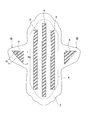
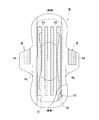
- the sanitary napkin 1 has a liquid-impervious back sheet 2 made of a polyethylene sheet, a polypropylene sheet, etc.
- the liquid surface sheet 3 the absorbent body 4 made of cotton-like pulp or synthetic pulp interposed between the two sheets 2 and 3, and the absorbent body 4 for maintaining the shape of the absorbent body 4 and improving the diffusibility.
- Crepe paper 5 surrounding the sheet a second sheet 6 made of a hydrophilic non-woven fabric interposed between the liquid-permeable surface sheet 3 and the crepe paper 5, and sides formed along the longitudinal direction on both sides of the surface. It is comprised from the nonwoven fabric 7,7.
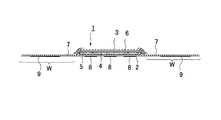
- the outer edge portions of the liquid-impervious back sheet 2 and the liquid-permeable surface sheet 3 are joined by an adhesive such as hot melt or an adhesive means such as heat seal.
- the liquid-impervious back sheet 2 and the side nonwoven fabric 7 that extend laterally from the absorbent body 4 at both side edges thereof are bonded to each other by an adhesive such as hot melt or an adhesive means such as heat seal.
- the structure of the sanitary napkin 1 will be described in detail.
- a sheet material having at least water shielding properties such as an olefin resin sheet such as polyethylene or polypropylene is used.
- a laminated nonwoven fabric obtained by laminating a nonwoven fabric on a polyethylene sheet or the like, or A nonwoven fabric sheet (in this case, the waterproof film and the nonwoven fabric constitute a liquid-impervious back sheet) can be used after substantially impervious to liquid imperviousness by interposing a waterproof film.
- those having moisture permeability tend to be used from the viewpoint of preventing stuffiness.
- This water- and moisture-permeable sheet material is a microporous sheet obtained by forming a sheet by melting and kneading an inorganic filler in an olefin resin such as polyethylene or polypropylene, and then stretching in a uniaxial or biaxial direction. It is.
- the liquid-permeable surface sheet 3 is preferably a porous or non-porous nonwoven fabric or a porous plastic sheet.
- the material fibers constituting the nonwoven fabric include synthetic fibers such as polyethylene or polypropylene, synthetic fibers such as polyester and polyamide, recycled fibers such as rayon and cupra, and natural fibers such as cotton.
- a nonwoven fabric obtained by an appropriate processing method such as a lace method, a spun bond method, a thermal bond method, a melt blown method, or a needle punch method can be used.
- the spunlace method is excellent in terms of flexibility and drapeability
- the thermal bond method is excellent in terms of being bulky and soft.
- the absorbent body 4 interposed between the liquid-impervious back sheet 2 and the liquid-permeable top sheet 3 is composed of, for example, fluffy pulp and a water-absorbing polymer.
- the water-absorbing polymer is mixed in the pulp constituting the absorber, for example, as granular powder.
- the pulp include chemical fibers obtained from wood, cellulose fibers such as dissolved pulp, and artificial cellulose fibers such as rayon and acetate.
- Softwood pulp having a longer fiber length than hardwood pulp functions and It is preferably used in terms of price.
- the second sheet 6 made of a hydrophilic non-woven fabric interposed between the liquid-permeable surface sheet 3 and the crepe paper 5 is made of, for example, synthetic fibers such as olefin-based, polyester-based, and polyamide-based fibers such as polyethylene or polypropylene, and rayon.
- synthetic fibers such as olefin-based, polyester-based, and polyamide-based fibers such as polyethylene or polypropylene, and rayon.
- Synthetic fibers can be made to swell or become porous by a method such as partially dissolving the surface to make it porous and depositing metal hydroxide, etc., and applying capillary action to impart hydrophilicity.
- side non-woven fabrics 7 and 7 are provided on both sides of the sanitary napkin 1 along the longitudinal direction and almost the entire length of the napkin 1, respectively.
- Wing-like flaps W, W are formed by a part of the liquid-impervious back sheet 2 that extends sideways and also extends sideways. The wing-shaped flap W will be described in detail later.
- a water-repellent treated nonwoven fabric or a hydrophilic treated nonwoven fabric can be used from the viewpoint of important functions. For example, if importance is placed on functions such as preventing permeation of menstrual blood or vaginal discharge, or enhancing the touch feeling, water repellent treatment coated with silicon, paraffin or alkylchromic chloride water repellent It is desirable to use a nonwoven fabric.
- a method of polymerizing a compound having a hydrophilic group for example, an oxidation product of polyethylene glycol, in the process of producing a synthetic fiber, ,
- a metal salt such as stannic chloride
- partially dissolving the surface to make it porous and depositing metal hydroxides to swell or make the synthetic fiber porous, applying capillary action to make it hydrophilic
- the hydrophilic treatment nonwoven fabric which gave is used.
- the non-skin contact surface of the main body part in which the absorbent body 4 is interposed between the liquid-permeable top sheet 3 and the liquid-impervious back sheet 2 is for fixing to the underwear.
- a wings prevention adhesive layer 9 is formed on the surface of the wing-shaped flaps W, W on the liquid-impermeable back sheet 2 side, and the wings prevention adhesive layers 9, 9 are not shown. Covered with a release material.
- the release material is formed by joining the release material for the main body and the release material for wings arranged in the transverse direction at an intersection so that the release material can be removed with a single peeling operation.
- W and W may be so-called belly folds that fold to the liquid-permeable topsheet 3 side in the individual packaging state, or may be so-called back folds that fold to the liquid-impermeable backsheet 2 side.
- a release treatment liquid such as a silicone resin, a fluorine resin, or a tetrafluoroethylene resin is applied to the contact surfaces with respect to the anti-displacement adhesive layers 8 and 9, or spray coating is performed.
- a release-treated paper or plastic sheet can be used.
- a styrenic polymer for example, a styrenic polymer, a tackifier, or a plasticizer that is a main component is preferably used.
- the styrenic polymer include styrene-ethylene-butylene-styrene block copolymers, styrene-butylene-styrene block copolymers, and styrene-isobutylene-styrene copolymers. It may be used or two or more polymer blends. Of these, a styrene-ethylene-butylene-styrene block copolymer is preferred because of its good thermal stability.
- tackifier and plasticizer those that are solid at room temperature can be preferably used.
- the tackifier include C5 petroleum resins, C9 petroleum resins, dicyclopentadiene petroleum resins, and rosin petroleum resins.
- Polyterpene resin, terpene phenol resin, etc., and examples of the plasticizer include monomer plasticizers such as trifresil phosphate, dibutyl phthalate, dioctyl phthalate, and polymer plasticizers such as vinyl polymers and polyesters. It is done.
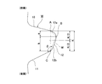
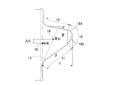
- the wing-shaped flap W includes a front outline 10 extending outward from the main body portion, a rear outline 11 extending outward from the main portion, and the front outline 10. And an outer shape composed of a front end side outline 12 connecting the rear outline 11.
- the front end side outline 12 includes a front end side outline front part 12a extending outward from the end A of the front side outline 10, and a front end side outline extending outward from the end C of the rear outline 11.
- the rear part 12b is comprised. As shown in FIG. 4, the end A of the front outline 10 and the end C of the rear outline 11 are straight lines when the front outline 10 or the rear outline 11 is formed as a straight line.
- the front outline 10 or the rear outline 11 is formed by a wavy line consisting of a combination of a convex curve and a concave curve, refers to the part away from the tangent line connecting the tops of the convex curves,
- the front outer shape line 10 or the rear outer shape line 11 is formed as a curve, it indicates a portion where a curve where the radius of curvature suddenly decreases or the position of the center of curvature changes abruptly starts.
- the intersection B between the front end side outline front portion 12a and the front end side outline rear portion 12b constitutes the outermost end in the width direction of the wing-shaped flap W.
- the outermost end in the width direction of the wing-shaped flap W is a front end portion in the width direction in which the outline of the wing-shaped flap W is in contact with the napkin longitudinal direction line M on the outermost side.
- intersection B is located on the front side of the napkin from the center point (K / 2) of the length K in the napkin longitudinal direction between the end A of the front outline 10 and the end C of the rear outline 11. Yes. That is, as shown in FIG. 4, when the longitudinal lengths of the napkins of AB and BC are a and b, respectively, a ⁇ b may be satisfied, but preferably a: b is 1: 1.5 to 1: It is preferable to provide the point B at a position where it is about 3.
- FIG. 4 shows the outer side of line AC which ties the edge part A of the front side outline 10 and the edge part C of the back side outline 11 will be shown.
- An outer bulging portion having the apex at the widthwise outer end B of the wing-shaped flap W biased to the front side of the napkin from the middle point is formed.
- the triangle ABC is a basic shape
- the side AB and the side BC are each configured by a curve, a straight line, or a combination thereof.
- the sides AB and BC are each configured by curves that bulge outward.
- the outer end on the front end side extends outward and obliquely forward toward the outer end B in the width direction of the wing-shaped flap W outside the end C of the rear outer contour line 11.
- a line rear portion 12b is provided.
- the wing-shaped flap W By making the wing-shaped flap W into such a shape, when the wing-shaped flap W is folded when the napkin is attached, the wing-shaped flap W can be folded back along the almost entire width of the wing-shaped flap W. Can be firmly fixed to the underwear. Specifically, as described in detail later, when the wing-shaped flap W is folded, as shown in FIG. 8 (B), the rear outline 11 of the wing-shaped flap W is moved from the proximal side to the distal direction. In the case of the conventional isosceles trapezoidal wing-shaped flap W, the length of the rear outline from the wing base end side to the tip end side is short, and the tip end side is further moved.
- the outline is formed by a straight line substantially parallel to the longitudinal direction of the napkin, there is a structural defect that it is difficult to move the hand up to the distal end side outline. For this reason, the wing-shaped flap cannot be properly folded at the normal folding position, and the wing-shaped flap may not be securely attached to the underwear. In particular, there is a problem in that the tip of the wing-shaped flap, which is difficult to reach along the hand, is easily peeled off.
- the hand when the wing-shaped flap W is folded back, the hand is moved forward along the rear outline 11 and the front outline rear 12b.
- the wing-shaped flap when the wing-shaped flap is folded back by hand, the wing-shaped flap can be worn in a proper state, and the hand can be placed up to the tip of the wing-shaped flap W, so that it can be firmly attached to the underwear.
- a straight line BC front end outline rear part 12 b connecting the end C of the rear outline 11 and the outermost end B in the width direction of the wing-shaped flap W, and the rear outline 11 Is preferably about 115 ° ⁇ ⁇ ⁇ 160 °.
- the front end side outline front part 12a and the front end side outline rear part 12b can be curved lines that bulge outward.
- the rear end 12b of the front end side With a curved line, the outer line from the end C of the rear outer line 11 to the outermost end B in the width direction of the wing-shaped flap W is connected by a smooth curve.
- the front end side outline front part 12a With a curved line, the end A of the front side outline 10 to the outermost end B in the width direction of the wing-shaped flap W are connected by a smooth curve. It becomes possible to prevent the part from being turned over.
- the rear outline 11 is preferably formed by a straight line or a curve that bulges slightly outward in order to make it easier for the hands to follow when the wing-shaped flap W is folded back. If the rear outline 11 is a wavy line or a curved line that bulges outward, when the hand is moved along the rear outline 11, a finger will be caught by the irregularities or curve of the wavy line. It is not preferable.
- the distal end side outline rear part 12b can also be constituted by a straight line. As a result, it is easy to place the hand linearly also at the rear end portion 12b on the front end side.
- the connection part (C) of the front end side outline rear part 12b and the rear side outline 11 it is desirable to connect with a gentle curve so that a corner
- the front outline 10 can be formed by a wavy line, a curve, or a combination thereof, as shown in FIG.
- the wavy line is composed of a combination of a convex curve 10b and a concave curve 10a.
- the wavy line is a line passing through the central portion of the convex curve 10b and the concave curve 10a.
- One or more convex portions and concave portions are formed.
- the curve is preferably a curve that bulges outward, but may be a curve that bulges inward.
- the front side outline 10 is formed by a wavy line, a curve, or a combination thereof, and the front side Since the wavy line or curve is provided in a series of continuous shapes from the outer shape line 10 to the front end side outer shape line front portion 12a, the effect of using the front outer shape line 10 as a wavy line or the like is more easily exhibited.
- the outer contour line of the wing-shaped flap W shown in FIG. 6 will be described in more detail.
- the front outer contour line 10 is formed by a wavy line composed of a convex curve 10b and a concave curve 10a, and from a curve connected to the side edge of the main body portion.
- a concave curve 10a is provided so as to extend, a convex curve 10b and a concave curve 10a are provided on the outer side thereof, and a distal end side outer shape so as to extend from the top (A) of the convex curve 10b provided on the outer side thereof.
- An arc that bulges outside the line front portion 12a starts and extends to point B.
- the front end side outline front portion 12 a is formed by an arc having a single radius of curvature Ra, and the center of curvature is located on a napkin width direction line passing through the point B.
- the curvature radius Ra is preferably about 10 mm to 20 mm.
- the rear outline 11 is formed by a straight line connected to the side edge of the main body portion by a curve, and starts a curve that bulges outside the distal end outline rear part 12b with the end C as a boundary. It extends to.
- the distal end side outline rear portion 12b is configured by a combination of arcs having a plurality of curvature radii, and at the connection portion with the point B, the arc component of the curvature radius Rb where the center of curvature is located on the napkin width direction line passing through the point B. have.
- the curvature radius Rb is preferably about 70 mm to 120 mm.
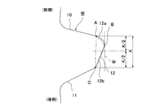
- the shape of the wing-shaped flap W is more than the angle ⁇ formed by the width direction line of the sanitary napkin 1 and the front outline 10.
- the angle ⁇ formed by the width direction line of the napkin 1 and the rear outline 11 is set larger, and the center of gravity 13 of the wing-shaped flap W is the center of the joint line 15 between the root of the wing-shaped flap W and the main body portion. It is preferable to deviate forward from the point 14 by ⁇ S.
- the front outline 10, the rear outline 11 and the tip outline 12 do not have to be straight lines, and may be wavy lines, curves, or combinations thereof. In this case, the angles ⁇ and ⁇ may have a gradient formed by the center line of these wavy or curved outlines.
- An angle ⁇ formed between the width direction line of the sanitary napkin 1 and the front outer shape line 10 is set to about 0 to 20 °, and an angle ⁇ formed between the width direction line of the sanitary napkin 1 and the rear outer shape line 11. Is preferably about 20 to 45 °.
- the angle ⁇ formed by the width direction line of the sanitary napkin 1 and the front outer shape line 10, the width direction line of the sanitary napkin 1 and the rear side The angle difference with the angle ⁇ formed with the outline 11 is preferably 25 ° or more. When this angle difference is 25 ° or more, a sufficient eccentric distance ⁇ S can be secured, and when the wing-shaped flap W is folded, the wing-shaped flap is folded by hand while moving the hand forward as described later. However, it will be able to be worn in the correct state.
- the wing-shaped flap W By making the wing-shaped flap W into the outer shape as described above, the wing-shaped flap can be easily folded back and adhered properly at the regular folding position without causing problems such as adhesion between adhesives or erroneous adhesion. At the same time, it is possible to bring advantages such as being able to attach the hand to the tip of the wing-shaped flap W and firmly attach it to the underwear. This point will be further described in detail by comparison with a conventional isosceles trapezoidal wing-shaped flap W (see FIG. 10).
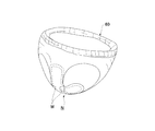
- the shorts 20 is lowered and lowered, so that the napkin 1 is located in front of the body as shown in FIG. Will be installed.
- FIG. 8 (A) In the case of a conventional isosceles trapezoidal wing-shaped flap W, as shown in FIG. 8 (A), a structure that cannot be mounted successfully unless the wing-shaped flap is folded back from the state where hands are attached to both sides of the napkin. It has become. However, because the wearing position is on the front side of the body, if you are not careful, the action of moving your hand to the front side (Fig. 8 (B)) will enter, and only a part of the wing-shaped flap will be folded back, Adhesives are bonded to each other and wrinkles and bulges are formed, and there are problems such as erroneous adhesion in which the wing-shaped flap W is folded back and bonded to the adhesive layer.
- the folding line of the wing-shaped flap may be bent at an angle. Therefore, in the present invention, as shown in FIG. 8 (B), when the wing-shaped flap W is folded, even if the wing-shaped flap is folded by hand while moving the hand to the front side, it is exactly legitimate.
- the wing shape is such that it can be mounted in a state and the hand can be placed to the tip of the wing-shaped flap W.
- FIG. 9 (A) shows the action force mechanism when folding back the conventional isosceles trapezoidal wing-shaped flap W.
- a load acting downward from the rear outline of the wing-shaped flap W to the tip side acts, and assuming a concentrated load ⁇ P that summarizes these distributed loads, the base point of the moment generated by this concentrated load ⁇ P is It becomes the center point 14 of the joint line 15 of the wing-shaped flap, and twisting occurs when the wing-shaped flap W is folded back, and the fold line 16 gradually progressing from the base end of the rear outline 11 is inclined outward. become.
- FIG. 9 (B) it is assumed that a downward load acts on the central portion of the inclined rear outline 11 and these distributed loads are summarized.
- the base point of the moment generated by this concentrated load ⁇ P is the center-of-gravity dividing point 13 ′ shifted to the front side of the center point 14 of the joint line 15 of the wing-shaped flap (almost 1: 2 division point of the joint line 15). Therefore, the folding line 16 gradually progressing from the base end of the rear outline 11 coincides with the joining line 15 and is folded at the regular folding position. become.
- the flap is folded back by tracing the outline of the rear side of the flap from the rear outline 11 to the rear outline 12b. For this reason, the folding line 16 gradually proceeds gradually from the base end of the rear outline 11 toward the front side.
- the wrap-shaped line RL can be formed without causing problems such as adhesion between adhesives or erroneous adhesion to the wing-shaped flap W. It will be folded.
- the protruding length L of the wing-shaped flap W is 40 to 50 mm, preferably longer than half the crotch width of the shorts 20. By making it longer than half of the crotch width of the shorts 20, it is possible to firmly fix the shorts to the shorts.
- the wings-stopping adhesive layer 9 provided on the back side of the wing-shaped flap W is such that the longitudinal width of the napkin 1 is narrower at the distal end side SL than at the proximal end side NL.
- SYMBOLS 1 Sanitary napkin, 2 ... Liquid impervious back sheet, 3 ... Liquid permeable top sheet, 4 ... Absorber, 5 ... Crepe paper, 6 ... Second sheet, 7 ... Side nonwoven fabric, 8 ... Main body slip prevention adhesive Layer, 9 ... Wingsling prevention adhesive layer, 10 ... front side outline, 11 ... rear side outline, 12 ... tip side outline, 12a ... tip side outline front, 12b ... tip side outline rear, A ... End of front outline 10, B: outermost end in width direction of wing-shaped flap W, C: end of rear outline 11, W: Wing-shaped flap
Abstract
Description
前記ウイング状フラップは、本体部分から外方に延びる前側外形線と、本体部分から外方に延びる後側外形線と、前記前側外形線と後側外形線とを繋ぐ先端側外形線とからなり、
前記先端側外形線は、前記前側外形線から外方に延びる先端側外形線前部と、前記後側外形線から外方に延びる先端側外形線後部とを有し、前記先端側外形線前部と先端側外形線後部との交点が、前記ウイング状フラップの幅方向最外側端部をなすとともに、前記前側外形線の端部と前記後側外形線の端部との吸収性物品の長手方向長さの中央点より前側に位置していることを特徴とする吸収性物品が提供される。
本発明に係る生理用ナプキン1は、図1~図3に示されるように、ポリエチレンシート、ポリプロピレンシートなどからなる不透液性裏面シート2と、経血やおりものなどを速やかに透過させる透液性表面シート3と、これら両シート2,3間に介在された綿状パルプまたは合成パルプなどからなる吸収体4と、この吸収体4の形状保持および拡散性向上のために前記吸収体4を囲繞するクレープ紙5と、前記透液性表面シート3とクレープ紙5との間に介在された親水性不織布からなるセカンドシート6と、表面両側部にそれぞれ長手方向に沿って形成されたサイド不織布7,7とから構成されている。前記吸収体4の周囲において、その上下端縁部では、前記不透液性裏面シート2と透液性表面シート3との外縁部がホットメルトなどの接着剤やヒートシール等の接着手段によって接合され、またその両側縁部では吸収体4よりも側方に延出している前記不透液性裏面シート2と前記サイド不織布7とがホットメルトなどの接着剤やヒートシール等の接着手段によって接合されている。
前記不透液性裏面シート2は、ポリエチレンやポリプロピレン等のオレフィン系樹脂シートなどの少なくとも遮水性を有するシート材が用いられるが、この他にポリエチレンシート等に不織布を積層したラミネート不織布や、さらには防水フィルムを介在して実質的に不透液性を確保した上で不織布シート(この場合には防水フィルムと不織布とで不透液性裏面シートを構成する。)などを用いることができる。近年はムレ防止の観点から透湿性を有するものが用いられる傾向にある。この遮水・透湿性シート材は、ポリエチレンやポリプロピレン等のオレフィン系樹脂中に無機充填剤を溶融混練してシートを成形した後、一軸または二軸方向に延伸することにより得られる微多孔性シートである。
前記ウイング状フラップWは、詳細には図4に示されるように、本体部分から外方に延びる前側外形線10と、本体部分から外方に延びる後側外形線11と、前記前側外形線10と後側外形線11とを繋ぐ先端側外形線12とからなる外形状を成す。
Claims (4)
- 透液性表面シートと不透液性裏面シートとの間に吸収体が介在された本体部分の両側部に夫々、装着時に下着のクロッチ部分を巻き込むようにして固定されるウイング状フラップが形成された吸収性物品において、
前記ウイング状フラップは、本体部分から外方に延びる前側外形線と、本体部分から外方に延びる後側外形線と、前記前側外形線と後側外形線とを繋ぐ先端側外形線とからなり、
前記先端側外形線は、前記前側外形線から外方に延びる先端側外形線前部と、前記後側外形線から外方に延びる先端側外形線後部とを有し、前記先端側外形線前部と先端側外形線後部との交点が、前記ウイング状フラップの幅方向最外側端部をなすとともに、前記前側外形線の端部と前記後側外形線の端部との吸収性物品の長手方向長さの中央点より前側に位置していることを特徴とする吸収性物品。 - 前記前側外形線は、波状線、曲線又はこれらの組み合わせからなる請求項1記載の吸収性物品。
- 前記先端側外形線後部は、曲線、直線又はこれらの組み合わせからなる請求項1、2いずれかに記載の吸収性物品。
- 前記後側外形線は、直線からなる請求項1~3いずれかに記載の吸収性物品。
Priority Applications (4)
| Application Number | Priority Date | Filing Date | Title |
|---|---|---|---|
| US15/039,239 US10258513B2 (en) | 2013-11-25 | 2014-11-20 | Absorbent article |
| CN201480064324.XA CN105764460B (zh) | 2013-11-25 | 2014-11-20 | 吸收性物品 |
| EP14863283.9A EP3075365B1 (en) | 2013-11-25 | 2014-11-20 | Absorbent article |
| KR1020167015874A KR102390577B1 (ko) | 2013-11-25 | 2014-11-20 | 흡수성 물품 |
Applications Claiming Priority (2)
| Application Number | Priority Date | Filing Date | Title |
|---|---|---|---|
| JP2013242628A JP6005027B2 (ja) | 2013-11-25 | 2013-11-25 | 吸収性物品 |
| JP2013-242628 | 2013-11-25 |
Publications (1)
| Publication Number | Publication Date |
|---|---|
| WO2015076337A1 true WO2015076337A1 (ja) | 2015-05-28 |
Family
ID=53179597
Family Applications (1)
| Application Number | Title | Priority Date | Filing Date |
|---|---|---|---|
| PCT/JP2014/080780 WO2015076337A1 (ja) | 2013-11-25 | 2014-11-20 | 吸収性物品 |
Country Status (6)
| Country | Link |
|---|---|
| US (1) | US10258513B2 (ja) |
| EP (1) | EP3075365B1 (ja) |
| JP (1) | JP6005027B2 (ja) |
| KR (1) | KR102390577B1 (ja) |
| CN (1) | CN105764460B (ja) |
| WO (1) | WO2015076337A1 (ja) |
Families Citing this family (12)
| Publication number | Priority date | Publication date | Assignee | Title |
|---|---|---|---|---|
| JP6668011B2 (ja) * | 2015-07-31 | 2020-03-18 | 大王製紙株式会社 | 吸収性物品 |
| WO2018209228A1 (en) * | 2017-05-12 | 2018-11-15 | The Procter & Gamble Company | Feminine hygiene article |
| US11065163B2 (en) | 2017-05-12 | 2021-07-20 | The Procter & Gamble Company | Feminine hygiene article with improved wings |
| EP3720405A1 (en) * | 2017-05-12 | 2020-10-14 | The Procter and Gamble Company | Feminine hygiene article |
| EP3621572A1 (en) | 2017-05-12 | 2020-03-18 | The Procter and Gamble Company | Feminine hygiene article |
| EP3624747B1 (en) | 2017-05-17 | 2023-05-03 | The Procter & Gamble Company | Method and apparatus for drying inks printed on heat sensitive absorbent article components |
| JP6976402B2 (ja) * | 2017-07-07 | 2021-12-08 | エシティ・ハイジーン・アンド・ヘルス・アクチエボラグ | 吸収性物品および吸収性物品を製造するための方法 |
| WO2019007529A1 (en) * | 2017-07-07 | 2019-01-10 | Essity Hygiene And Health Aktiebolag | ABSORBENT ARTICLE AND METHOD OF MANUFACTURING AN ABSORBENT ARTICLE |
| USD902394S1 (en) | 2018-07-02 | 2020-11-17 | The Procter & Gamble Company | Sanitary napkin |
| USD917692S1 (en) | 2019-03-19 | 2021-04-27 | Johnson & Johnson Consumer Inc. | Absorbent article |
| USD919084S1 (en) * | 2019-03-19 | 2021-05-11 | Johnson & Johnson Consumer Inc. | Absorbent article |
| USD978342S1 (en) * | 2019-09-06 | 2023-02-14 | Kimberly-Clark Worldwide, Inc. | Feminine pad |
Citations (5)
| Publication number | Priority date | Publication date | Assignee | Title |
|---|---|---|---|---|
| JP2003111799A (ja) | 2001-10-03 | 2003-04-15 | Daio Paper Corp | 吸収性物品 |
| JP2004113590A (ja) | 2002-09-27 | 2004-04-15 | Daio Paper Corp | 吸収性物品 |
| JP2008012098A (ja) | 2006-07-06 | 2008-01-24 | Kao Corp | 吸収性物品 |
| JP2013176695A (ja) * | 2013-06-25 | 2013-09-09 | Daio Paper Corp | 吸収性物品 |
| JP2013220225A (ja) * | 2012-04-17 | 2013-10-28 | Kao Corp | 吸収性物品 |
Family Cites Families (6)
| Publication number | Priority date | Publication date | Assignee | Title |
|---|---|---|---|---|
| US6569138B2 (en) * | 2000-04-13 | 2003-05-27 | Sca Hygiene Products Ab | Sanitary napkin |
| US20050124959A1 (en) * | 2003-12-09 | 2005-06-09 | Kimberly-Clark Worldwide, Inc. | Absorbent articles with asymmetric protective wing portions |
| JP2009125430A (ja) * | 2007-11-27 | 2009-06-11 | Daio Paper Corp | 吸収性物品 |
| JP5059899B2 (ja) * | 2010-03-29 | 2012-10-31 | 大王製紙株式会社 | 吸収性物品の製造方法 |
| JP5856789B2 (ja) * | 2011-09-30 | 2016-02-10 | 大王製紙株式会社 | 吸収性物品 |
| EP2774590B1 (en) * | 2011-10-31 | 2017-08-16 | Daio Paper Corporation | Absorbent article |
-
2013
- 2013-11-25 JP JP2013242628A patent/JP6005027B2/ja active Active
-
2014
- 2014-11-20 EP EP14863283.9A patent/EP3075365B1/en active Active
- 2014-11-20 CN CN201480064324.XA patent/CN105764460B/zh active Active
- 2014-11-20 WO PCT/JP2014/080780 patent/WO2015076337A1/ja active Application Filing
- 2014-11-20 US US15/039,239 patent/US10258513B2/en active Active
- 2014-11-20 KR KR1020167015874A patent/KR102390577B1/ko active IP Right Grant
Patent Citations (5)
| Publication number | Priority date | Publication date | Assignee | Title |
|---|---|---|---|---|
| JP2003111799A (ja) | 2001-10-03 | 2003-04-15 | Daio Paper Corp | 吸収性物品 |
| JP2004113590A (ja) | 2002-09-27 | 2004-04-15 | Daio Paper Corp | 吸収性物品 |
| JP2008012098A (ja) | 2006-07-06 | 2008-01-24 | Kao Corp | 吸収性物品 |
| JP2013220225A (ja) * | 2012-04-17 | 2013-10-28 | Kao Corp | 吸収性物品 |
| JP2013176695A (ja) * | 2013-06-25 | 2013-09-09 | Daio Paper Corp | 吸収性物品 |
Also Published As
| Publication number | Publication date |
|---|---|
| US10258513B2 (en) | 2019-04-16 |
| KR20160090320A (ko) | 2016-07-29 |
| CN105764460A (zh) | 2016-07-13 |
| EP3075365A1 (en) | 2016-10-05 |
| JP2015100502A (ja) | 2015-06-04 |
| EP3075365B1 (en) | 2019-07-03 |
| US20160361210A1 (en) | 2016-12-15 |
| KR102390577B1 (ko) | 2022-04-25 |
| CN105764460B (zh) | 2019-12-17 |
| JP6005027B2 (ja) | 2016-10-12 |
| EP3075365A4 (en) | 2017-05-24 |
Similar Documents
| Publication | Publication Date | Title |
|---|---|---|
| JP6005027B2 (ja) | 吸収性物品 | |
| KR101527421B1 (ko) | 흡수성물품 | |
| JP2015100502A5 (ja) | ||
| JP2009125430A5 (ja) | ||
| JP5681446B2 (ja) | 吸収性物品 | |
| JP5856789B2 (ja) | 吸収性物品 | |
| CN109475453B (zh) | 吸收性物品 | |
| JP6031444B2 (ja) | 吸収性物品 | |
| JP2008161250A (ja) | 吸収性物品 | |
| JP5832164B2 (ja) | 吸収性物品 | |
| JP5059899B2 (ja) | 吸収性物品の製造方法 | |
| JP5826216B2 (ja) | 吸収性物品 | |
| JP5306419B2 (ja) | 吸収性物品 | |
| JP2017080244A (ja) | 吸収性物品 | |
| JP6151510B2 (ja) | 吸収性物品 | |
| JP2013121462A5 (ja) | ||
| JP5876243B2 (ja) | 吸収性物品 | |
| JP5968641B2 (ja) | 吸収性物品 | |
| JP7286371B2 (ja) | 吸収性物品 | |
| JP6668011B2 (ja) | 吸収性物品 | |
| JP2019058427A (ja) | 吸収性物品 |
Legal Events
| Date | Code | Title | Description |
|---|---|---|---|
| 121 | Ep: the epo has been informed by wipo that ep was designated in this application |
Ref document number: 14863283 Country of ref document: EP Kind code of ref document: A1 |
|
| NENP | Non-entry into the national phase |
Ref country code: DE |
|
| WWE | Wipo information: entry into national phase |
Ref document number: 15039239 Country of ref document: US |
|
| REEP | Request for entry into the european phase |
Ref document number: 2014863283 Country of ref document: EP |
|
| WWE | Wipo information: entry into national phase |
Ref document number: 2014863283 Country of ref document: EP |
|
| ENP | Entry into the national phase |
Ref document number: 20167015874 Country of ref document: KR Kind code of ref document: A |