EP3075365B1 - Absorbent article - Google Patents
Absorbent article Download PDFInfo
- Publication number
- EP3075365B1 EP3075365B1 EP14863283.9A EP14863283A EP3075365B1 EP 3075365 B1 EP3075365 B1 EP 3075365B1 EP 14863283 A EP14863283 A EP 14863283A EP 3075365 B1 EP3075365 B1 EP 3075365B1
- Authority
- EP
- European Patent Office
- Prior art keywords
- side outline
- wing
- outline
- tip end
- end portion
- Prior art date
- Legal status (The legal status is an assumption and is not a legal conclusion. Google has not performed a legal analysis and makes no representation as to the accuracy of the status listed.)
- Active
Links
- 239000002250 absorbent Substances 0.000 title claims description 54
- 230000002745 absorbent Effects 0.000 title claims description 52
- 239000007788 liquid Substances 0.000 claims description 31
- 239000004745 nonwoven fabric Substances 0.000 description 22
- 238000000034 method Methods 0.000 description 18
- -1 polyethylene Polymers 0.000 description 17
- 239000012790 adhesive layer Substances 0.000 description 13
- 238000006073 displacement reaction Methods 0.000 description 11
- 239000000463 material Substances 0.000 description 11
- 230000002265 prevention Effects 0.000 description 11
- 239000000853 adhesive Substances 0.000 description 10
- 230000001070 adhesive effect Effects 0.000 description 10
- 229920005989 resin Polymers 0.000 description 9
- 239000011347 resin Substances 0.000 description 9
- 239000000123 paper Substances 0.000 description 8
- 239000004698 Polyethylene Substances 0.000 description 7
- 229920000573 polyethylene Polymers 0.000 description 7
- 239000000835 fiber Substances 0.000 description 6
- 239000004014 plasticizer Substances 0.000 description 6
- 229920002994 synthetic fiber Polymers 0.000 description 6
- 239000012209 synthetic fiber Substances 0.000 description 6
- 239000004743 Polypropylene Substances 0.000 description 5
- 229920001155 polypropylene Polymers 0.000 description 5
- PPBRXRYQALVLMV-UHFFFAOYSA-N Styrene Chemical compound C=CC1=CC=CC=C1 PPBRXRYQALVLMV-UHFFFAOYSA-N 0.000 description 4
- 150000001336 alkenes Chemical class 0.000 description 4
- 239000008280 blood Substances 0.000 description 4
- 210000004369 blood Anatomy 0.000 description 4
- 230000002175 menstrual effect Effects 0.000 description 4
- 239000002184 metal Substances 0.000 description 4
- 229910052751 metal Inorganic materials 0.000 description 4
- 239000003208 petroleum Substances 0.000 description 4
- 229920000642 polymer Polymers 0.000 description 4
- 229920000297 Rayon Polymers 0.000 description 3
- 210000003756 cervix mucus Anatomy 0.000 description 3
- 238000010586 diagram Methods 0.000 description 3
- 239000010410 layer Substances 0.000 description 3
- 230000007246 mechanism Effects 0.000 description 3
- 239000002985 plastic film Substances 0.000 description 3
- 229920000728 polyester Polymers 0.000 description 3
- 238000003672 processing method Methods 0.000 description 3
- 239000002964 rayon Substances 0.000 description 3
- 239000005871 repellent Substances 0.000 description 3
- 229920006132 styrene block copolymer Polymers 0.000 description 3
- 206010046901 vaginal discharge Diseases 0.000 description 3
- XLYOFNOQVPJJNP-UHFFFAOYSA-N water Substances O XLYOFNOQVPJJNP-UHFFFAOYSA-N 0.000 description 3
- 229920003043 Cellulose fiber Polymers 0.000 description 2
- 229920000742 Cotton Polymers 0.000 description 2
- NBIIXXVUZAFLBC-UHFFFAOYSA-N Phosphoric acid Chemical compound OP(O)(O)=O NBIIXXVUZAFLBC-UHFFFAOYSA-N 0.000 description 2
- 239000004952 Polyamide Substances 0.000 description 2
- 239000002202 Polyethylene glycol Substances 0.000 description 2
- 229910021627 Tin(IV) chloride Inorganic materials 0.000 description 2
- 238000010521 absorption reaction Methods 0.000 description 2
- 210000001124 body fluid Anatomy 0.000 description 2
- 239000010839 body fluid Substances 0.000 description 2
- 150000001875 compounds Chemical class 0.000 description 2
- 238000000151 deposition Methods 0.000 description 2
- DOIRQSBPFJWKBE-UHFFFAOYSA-N dibutyl phthalate Chemical compound CCCCOC(=O)C1=CC=CC=C1C(=O)OCCCC DOIRQSBPFJWKBE-UHFFFAOYSA-N 0.000 description 2
- 238000009826 distribution Methods 0.000 description 2
- 230000000694 effects Effects 0.000 description 2
- 239000012943 hotmelt Substances 0.000 description 2
- XLYOFNOQVPJJNP-UHFFFAOYSA-M hydroxide Chemical compound [OH-] XLYOFNOQVPJJNP-UHFFFAOYSA-M 0.000 description 2
- 238000004519 manufacturing process Methods 0.000 description 2
- JRZJOMJEPLMPRA-UHFFFAOYSA-N olefin Natural products CCCCCCCC=C JRZJOMJEPLMPRA-UHFFFAOYSA-N 0.000 description 2
- 230000003647 oxidation Effects 0.000 description 2
- 238000007254 oxidation reaction Methods 0.000 description 2
- 229920002647 polyamide Polymers 0.000 description 2
- 229920001223 polyethylene glycol Polymers 0.000 description 2
- 238000006116 polymerization reaction Methods 0.000 description 2
- 150000003839 salts Chemical class 0.000 description 2
- HPGGPRDJHPYFRM-UHFFFAOYSA-J tin(iv) chloride Chemical compound Cl[Sn](Cl)(Cl)Cl HPGGPRDJHPYFRM-UHFFFAOYSA-J 0.000 description 2
- 230000037303 wrinkles Effects 0.000 description 2
- HECLRDQVFMWTQS-RGOKHQFPSA-N 1755-01-7 Chemical compound C1[C@H]2[C@@H]3CC=C[C@@H]3[C@@H]1C=C2 HECLRDQVFMWTQS-RGOKHQFPSA-N 0.000 description 1
- RSWGJHLUYNHPMX-UHFFFAOYSA-N Abietic-Saeure Natural products C12CCC(C(C)C)=CC2=CCC2C1(C)CCCC2(C)C(O)=O RSWGJHLUYNHPMX-UHFFFAOYSA-N 0.000 description 1
- QTBSBXVTEAMEQO-UHFFFAOYSA-M Acetate Chemical compound CC([O-])=O QTBSBXVTEAMEQO-UHFFFAOYSA-M 0.000 description 1
- MQIUGAXCHLFZKX-UHFFFAOYSA-N Di-n-octyl phthalate Natural products CCCCCCCCOC(=O)C1=CC=CC=C1C(=O)OCCCCCCCC MQIUGAXCHLFZKX-UHFFFAOYSA-N 0.000 description 1
- 229920000875 Dissolving pulp Polymers 0.000 description 1
- PYVHTIWHNXTVPF-UHFFFAOYSA-N F.F.F.F.C=C Chemical group F.F.F.F.C=C PYVHTIWHNXTVPF-UHFFFAOYSA-N 0.000 description 1
- YCKRFDGAMUMZLT-UHFFFAOYSA-N Fluorine atom Chemical compound [F] YCKRFDGAMUMZLT-UHFFFAOYSA-N 0.000 description 1
- 206010021639 Incontinence Diseases 0.000 description 1
- 229920001131 Pulp (paper) Polymers 0.000 description 1
- KHPCPRHQVVSZAH-HUOMCSJISA-N Rosin Natural products O(C/C=C/c1ccccc1)[C@H]1[C@H](O)[C@@H](O)[C@@H](O)[C@@H](CO)O1 KHPCPRHQVVSZAH-HUOMCSJISA-N 0.000 description 1
- XUIMIQQOPSSXEZ-UHFFFAOYSA-N Silicon Chemical compound [Si] XUIMIQQOPSSXEZ-UHFFFAOYSA-N 0.000 description 1
- 210000001015 abdomen Anatomy 0.000 description 1
- 229910000147 aluminium phosphate Inorganic materials 0.000 description 1
- 230000003373 anti-fouling effect Effects 0.000 description 1
- BJQHLKABXJIVAM-UHFFFAOYSA-N bis(2-ethylhexyl) phthalate Chemical compound CCCCC(CC)COC(=O)C1=CC=CC=C1C(=O)OCC(CC)CCCC BJQHLKABXJIVAM-UHFFFAOYSA-N 0.000 description 1
- 230000008859 change Effects 0.000 description 1
- 229960000359 chromic chloride Drugs 0.000 description 1
- 235000007831 chromium(III) chloride Nutrition 0.000 description 1
- 239000011636 chromium(III) chloride Substances 0.000 description 1
- 239000011248 coating agent Substances 0.000 description 1
- 238000000576 coating method Methods 0.000 description 1
- 229920001577 copolymer Polymers 0.000 description 1
- 230000003247 decreasing effect Effects 0.000 description 1
- 230000002708 enhancing effect Effects 0.000 description 1
- 229910052731 fluorine Inorganic materials 0.000 description 1
- 239000011737 fluorine Substances 0.000 description 1
- 230000005484 gravity Effects 0.000 description 1
- 239000011121 hardwood Substances 0.000 description 1
- 239000011256 inorganic filler Substances 0.000 description 1
- 229910003475 inorganic filler Inorganic materials 0.000 description 1
- 238000004898 kneading Methods 0.000 description 1
- 230000014759 maintenance of location Effects 0.000 description 1
- 238000002844 melting Methods 0.000 description 1
- 230000008018 melting Effects 0.000 description 1
- 239000012188 paraffin wax Substances 0.000 description 1
- 230000035699 permeability Effects 0.000 description 1
- 239000005011 phenolic resin Substances 0.000 description 1
- 229920002959 polymer blend Polymers 0.000 description 1
- 150000003097 polyterpenes Chemical class 0.000 description 1
- 239000000843 powder Substances 0.000 description 1
- 230000001681 protective effect Effects 0.000 description 1
- 230000002940 repellent Effects 0.000 description 1
- 238000000926 separation method Methods 0.000 description 1
- 229910052710 silicon Inorganic materials 0.000 description 1
- 239000010703 silicon Substances 0.000 description 1
- 229920002050 silicone resin Polymers 0.000 description 1
- 239000011122 softwood Substances 0.000 description 1
- 239000007787 solid Substances 0.000 description 1
- 238000005507 spraying Methods 0.000 description 1
- 150000003505 terpenes Chemical class 0.000 description 1
- 235000007586 terpenes Nutrition 0.000 description 1
- KHPCPRHQVVSZAH-UHFFFAOYSA-N trans-cinnamyl beta-D-glucopyranoside Natural products OC1C(O)C(O)C(CO)OC1OCC=CC1=CC=CC=C1 KHPCPRHQVVSZAH-UHFFFAOYSA-N 0.000 description 1
- 229920002554 vinyl polymer Polymers 0.000 description 1
- 239000002023 wood Substances 0.000 description 1
Images


Classifications
-
- A—HUMAN NECESSITIES
- A61—MEDICAL OR VETERINARY SCIENCE; HYGIENE
- A61F—FILTERS IMPLANTABLE INTO BLOOD VESSELS; PROSTHESES; DEVICES PROVIDING PATENCY TO, OR PREVENTING COLLAPSING OF, TUBULAR STRUCTURES OF THE BODY, e.g. STENTS; ORTHOPAEDIC, NURSING OR CONTRACEPTIVE DEVICES; FOMENTATION; TREATMENT OR PROTECTION OF EYES OR EARS; BANDAGES, DRESSINGS OR ABSORBENT PADS; FIRST-AID KITS
- A61F13/00—Bandages or dressings; Absorbent pads
- A61F13/15—Absorbent pads, e.g. sanitary towels, swabs or tampons for external or internal application to the body; Supporting or fastening means therefor; Tampon applicators
- A61F13/45—Absorbent pads, e.g. sanitary towels, swabs or tampons for external or internal application to the body; Supporting or fastening means therefor; Tampon applicators characterised by the shape
- A61F13/47—Sanitary towels, incontinence pads or napkins
- A61F13/4704—Sanitary towels, incontinence pads or napkins having preferential bending zones, e.g. fold lines or grooves
-
- A—HUMAN NECESSITIES
- A61—MEDICAL OR VETERINARY SCIENCE; HYGIENE
- A61F—FILTERS IMPLANTABLE INTO BLOOD VESSELS; PROSTHESES; DEVICES PROVIDING PATENCY TO, OR PREVENTING COLLAPSING OF, TUBULAR STRUCTURES OF THE BODY, e.g. STENTS; ORTHOPAEDIC, NURSING OR CONTRACEPTIVE DEVICES; FOMENTATION; TREATMENT OR PROTECTION OF EYES OR EARS; BANDAGES, DRESSINGS OR ABSORBENT PADS; FIRST-AID KITS
- A61F13/00—Bandages or dressings; Absorbent pads
- A61F13/15—Absorbent pads, e.g. sanitary towels, swabs or tampons for external or internal application to the body; Supporting or fastening means therefor; Tampon applicators
- A61F13/45—Absorbent pads, e.g. sanitary towels, swabs or tampons for external or internal application to the body; Supporting or fastening means therefor; Tampon applicators characterised by the shape
- A61F13/47—Sanitary towels, incontinence pads or napkins
- A61F13/472—Sanitary towels, incontinence pads or napkins specially adapted for female use
- A61F13/47236—Sanitary towels, incontinence pads or napkins specially adapted for female use characterised by an unusual contour
-
- A—HUMAN NECESSITIES
- A61—MEDICAL OR VETERINARY SCIENCE; HYGIENE
- A61F—FILTERS IMPLANTABLE INTO BLOOD VESSELS; PROSTHESES; DEVICES PROVIDING PATENCY TO, OR PREVENTING COLLAPSING OF, TUBULAR STRUCTURES OF THE BODY, e.g. STENTS; ORTHOPAEDIC, NURSING OR CONTRACEPTIVE DEVICES; FOMENTATION; TREATMENT OR PROTECTION OF EYES OR EARS; BANDAGES, DRESSINGS OR ABSORBENT PADS; FIRST-AID KITS
- A61F13/00—Bandages or dressings; Absorbent pads
- A61F13/15—Absorbent pads, e.g. sanitary towels, swabs or tampons for external or internal application to the body; Supporting or fastening means therefor; Tampon applicators
- A61F13/45—Absorbent pads, e.g. sanitary towels, swabs or tampons for external or internal application to the body; Supporting or fastening means therefor; Tampon applicators characterised by the shape
- A61F13/47—Sanitary towels, incontinence pads or napkins
- A61F13/476—Sanitary towels, incontinence pads or napkins characterised by encircling the crotch region of the undergarment
-
- A—HUMAN NECESSITIES
- A61—MEDICAL OR VETERINARY SCIENCE; HYGIENE
- A61F—FILTERS IMPLANTABLE INTO BLOOD VESSELS; PROSTHESES; DEVICES PROVIDING PATENCY TO, OR PREVENTING COLLAPSING OF, TUBULAR STRUCTURES OF THE BODY, e.g. STENTS; ORTHOPAEDIC, NURSING OR CONTRACEPTIVE DEVICES; FOMENTATION; TREATMENT OR PROTECTION OF EYES OR EARS; BANDAGES, DRESSINGS OR ABSORBENT PADS; FIRST-AID KITS
- A61F13/00—Bandages or dressings; Absorbent pads
- A61F13/15—Absorbent pads, e.g. sanitary towels, swabs or tampons for external or internal application to the body; Supporting or fastening means therefor; Tampon applicators
- A61F13/51—Absorbent pads, e.g. sanitary towels, swabs or tampons for external or internal application to the body; Supporting or fastening means therefor; Tampon applicators characterised by the outer layers
- A61F13/514—Backsheet, i.e. the impermeable cover or layer furthest from the skin
- A61F13/51401—Backsheet, i.e. the impermeable cover or layer furthest from the skin characterised by the material
-
- A—HUMAN NECESSITIES
- A61—MEDICAL OR VETERINARY SCIENCE; HYGIENE
- A61F—FILTERS IMPLANTABLE INTO BLOOD VESSELS; PROSTHESES; DEVICES PROVIDING PATENCY TO, OR PREVENTING COLLAPSING OF, TUBULAR STRUCTURES OF THE BODY, e.g. STENTS; ORTHOPAEDIC, NURSING OR CONTRACEPTIVE DEVICES; FOMENTATION; TREATMENT OR PROTECTION OF EYES OR EARS; BANDAGES, DRESSINGS OR ABSORBENT PADS; FIRST-AID KITS
- A61F13/00—Bandages or dressings; Absorbent pads
- A61F13/15—Absorbent pads, e.g. sanitary towels, swabs or tampons for external or internal application to the body; Supporting or fastening means therefor; Tampon applicators
- A61F13/51—Absorbent pads, e.g. sanitary towels, swabs or tampons for external or internal application to the body; Supporting or fastening means therefor; Tampon applicators characterised by the outer layers
- A61F13/514—Backsheet, i.e. the impermeable cover or layer furthest from the skin
- A61F13/51474—Backsheet, i.e. the impermeable cover or layer furthest from the skin characterised by its structure
-
- A—HUMAN NECESSITIES
- A61—MEDICAL OR VETERINARY SCIENCE; HYGIENE
- A61F—FILTERS IMPLANTABLE INTO BLOOD VESSELS; PROSTHESES; DEVICES PROVIDING PATENCY TO, OR PREVENTING COLLAPSING OF, TUBULAR STRUCTURES OF THE BODY, e.g. STENTS; ORTHOPAEDIC, NURSING OR CONTRACEPTIVE DEVICES; FOMENTATION; TREATMENT OR PROTECTION OF EYES OR EARS; BANDAGES, DRESSINGS OR ABSORBENT PADS; FIRST-AID KITS
- A61F13/00—Bandages or dressings; Absorbent pads
- A61F13/15—Absorbent pads, e.g. sanitary towels, swabs or tampons for external or internal application to the body; Supporting or fastening means therefor; Tampon applicators
- A61F13/51—Absorbent pads, e.g. sanitary towels, swabs or tampons for external or internal application to the body; Supporting or fastening means therefor; Tampon applicators characterised by the outer layers
- A61F13/515—Absorbent pads, e.g. sanitary towels, swabs or tampons for external or internal application to the body; Supporting or fastening means therefor; Tampon applicators characterised by the outer layers characterised by the interconnection of the topsheet and the backsheet
-
- A—HUMAN NECESSITIES
- A61—MEDICAL OR VETERINARY SCIENCE; HYGIENE
- A61F—FILTERS IMPLANTABLE INTO BLOOD VESSELS; PROSTHESES; DEVICES PROVIDING PATENCY TO, OR PREVENTING COLLAPSING OF, TUBULAR STRUCTURES OF THE BODY, e.g. STENTS; ORTHOPAEDIC, NURSING OR CONTRACEPTIVE DEVICES; FOMENTATION; TREATMENT OR PROTECTION OF EYES OR EARS; BANDAGES, DRESSINGS OR ABSORBENT PADS; FIRST-AID KITS
- A61F13/00—Bandages or dressings; Absorbent pads
- A61F13/15—Absorbent pads, e.g. sanitary towels, swabs or tampons for external or internal application to the body; Supporting or fastening means therefor; Tampon applicators
- A61F13/53—Absorbent pads, e.g. sanitary towels, swabs or tampons for external or internal application to the body; Supporting or fastening means therefor; Tampon applicators characterised by the absorbing medium
- A61F13/539—Absorbent pads, e.g. sanitary towels, swabs or tampons for external or internal application to the body; Supporting or fastening means therefor; Tampon applicators characterised by the absorbing medium characterised by the connection of the absorbent layers with each other or with the outer layers
-
- A—HUMAN NECESSITIES
- A61—MEDICAL OR VETERINARY SCIENCE; HYGIENE
- A61F—FILTERS IMPLANTABLE INTO BLOOD VESSELS; PROSTHESES; DEVICES PROVIDING PATENCY TO, OR PREVENTING COLLAPSING OF, TUBULAR STRUCTURES OF THE BODY, e.g. STENTS; ORTHOPAEDIC, NURSING OR CONTRACEPTIVE DEVICES; FOMENTATION; TREATMENT OR PROTECTION OF EYES OR EARS; BANDAGES, DRESSINGS OR ABSORBENT PADS; FIRST-AID KITS
- A61F13/00—Bandages or dressings; Absorbent pads
- A61F13/15—Absorbent pads, e.g. sanitary towels, swabs or tampons for external or internal application to the body; Supporting or fastening means therefor; Tampon applicators
- A61F13/56—Supporting or fastening means
- A61F13/5605—Supporting or fastening means specially adapted for sanitary napkins or the like
- A61F13/5616—Supporting or fastening means specially adapted for sanitary napkins or the like using flaps, e.g. adhesive, for attachment to the undergarment
-
- A—HUMAN NECESSITIES
- A61—MEDICAL OR VETERINARY SCIENCE; HYGIENE
- A61F—FILTERS IMPLANTABLE INTO BLOOD VESSELS; PROSTHESES; DEVICES PROVIDING PATENCY TO, OR PREVENTING COLLAPSING OF, TUBULAR STRUCTURES OF THE BODY, e.g. STENTS; ORTHOPAEDIC, NURSING OR CONTRACEPTIVE DEVICES; FOMENTATION; TREATMENT OR PROTECTION OF EYES OR EARS; BANDAGES, DRESSINGS OR ABSORBENT PADS; FIRST-AID KITS
- A61F13/00—Bandages or dressings; Absorbent pads
- A61F13/15—Absorbent pads, e.g. sanitary towels, swabs or tampons for external or internal application to the body; Supporting or fastening means therefor; Tampon applicators
- A61F13/51—Absorbent pads, e.g. sanitary towels, swabs or tampons for external or internal application to the body; Supporting or fastening means therefor; Tampon applicators characterised by the outer layers
- A61F13/511—Topsheet, i.e. the permeable cover or layer facing the skin
- A61F13/51121—Topsheet, i.e. the permeable cover or layer facing the skin characterised by the material
- A61F2013/51143—Topsheet, i.e. the permeable cover or layer facing the skin characterised by the material being papers
-
- A—HUMAN NECESSITIES
- A61—MEDICAL OR VETERINARY SCIENCE; HYGIENE
- A61F—FILTERS IMPLANTABLE INTO BLOOD VESSELS; PROSTHESES; DEVICES PROVIDING PATENCY TO, OR PREVENTING COLLAPSING OF, TUBULAR STRUCTURES OF THE BODY, e.g. STENTS; ORTHOPAEDIC, NURSING OR CONTRACEPTIVE DEVICES; FOMENTATION; TREATMENT OR PROTECTION OF EYES OR EARS; BANDAGES, DRESSINGS OR ABSORBENT PADS; FIRST-AID KITS
- A61F13/00—Bandages or dressings; Absorbent pads
- A61F13/15—Absorbent pads, e.g. sanitary towels, swabs or tampons for external or internal application to the body; Supporting or fastening means therefor; Tampon applicators
- A61F13/51—Absorbent pads, e.g. sanitary towels, swabs or tampons for external or internal application to the body; Supporting or fastening means therefor; Tampon applicators characterised by the outer layers
- A61F13/511—Topsheet, i.e. the permeable cover or layer facing the skin
- A61F13/51121—Topsheet, i.e. the permeable cover or layer facing the skin characterised by the material
- A61F2013/51147—Topsheet, i.e. the permeable cover or layer facing the skin characterised by the material being polymeric films
-
- A—HUMAN NECESSITIES
- A61—MEDICAL OR VETERINARY SCIENCE; HYGIENE
- A61F—FILTERS IMPLANTABLE INTO BLOOD VESSELS; PROSTHESES; DEVICES PROVIDING PATENCY TO, OR PREVENTING COLLAPSING OF, TUBULAR STRUCTURES OF THE BODY, e.g. STENTS; ORTHOPAEDIC, NURSING OR CONTRACEPTIVE DEVICES; FOMENTATION; TREATMENT OR PROTECTION OF EYES OR EARS; BANDAGES, DRESSINGS OR ABSORBENT PADS; FIRST-AID KITS
- A61F13/00—Bandages or dressings; Absorbent pads
- A61F13/15—Absorbent pads, e.g. sanitary towels, swabs or tampons for external or internal application to the body; Supporting or fastening means therefor; Tampon applicators
- A61F13/51—Absorbent pads, e.g. sanitary towels, swabs or tampons for external or internal application to the body; Supporting or fastening means therefor; Tampon applicators characterised by the outer layers
- A61F13/514—Backsheet, i.e. the impermeable cover or layer furthest from the skin
- A61F13/51474—Backsheet, i.e. the impermeable cover or layer furthest from the skin characterised by its structure
- A61F2013/51486—Backsheet, i.e. the impermeable cover or layer furthest from the skin characterised by its structure with specially shaped backsheets
- A61F2013/51488—Backsheet, i.e. the impermeable cover or layer furthest from the skin characterised by its structure with specially shaped backsheets for napkins
-
- A—HUMAN NECESSITIES
- A61—MEDICAL OR VETERINARY SCIENCE; HYGIENE
- A61F—FILTERS IMPLANTABLE INTO BLOOD VESSELS; PROSTHESES; DEVICES PROVIDING PATENCY TO, OR PREVENTING COLLAPSING OF, TUBULAR STRUCTURES OF THE BODY, e.g. STENTS; ORTHOPAEDIC, NURSING OR CONTRACEPTIVE DEVICES; FOMENTATION; TREATMENT OR PROTECTION OF EYES OR EARS; BANDAGES, DRESSINGS OR ABSORBENT PADS; FIRST-AID KITS
- A61F13/00—Bandages or dressings; Absorbent pads
- A61F13/15—Absorbent pads, e.g. sanitary towels, swabs or tampons for external or internal application to the body; Supporting or fastening means therefor; Tampon applicators
- A61F13/53—Absorbent pads, e.g. sanitary towels, swabs or tampons for external or internal application to the body; Supporting or fastening means therefor; Tampon applicators characterised by the absorbing medium
- A61F13/539—Absorbent pads, e.g. sanitary towels, swabs or tampons for external or internal application to the body; Supporting or fastening means therefor; Tampon applicators characterised by the absorbing medium characterised by the connection of the absorbent layers with each other or with the outer layers
- A61F2013/5395—Absorbent pads, e.g. sanitary towels, swabs or tampons for external or internal application to the body; Supporting or fastening means therefor; Tampon applicators characterised by the absorbing medium characterised by the connection of the absorbent layers with each other or with the outer layers with thermoplastic agent, i.e. softened by heat
-
- A—HUMAN NECESSITIES
- A61—MEDICAL OR VETERINARY SCIENCE; HYGIENE
- A61F—FILTERS IMPLANTABLE INTO BLOOD VESSELS; PROSTHESES; DEVICES PROVIDING PATENCY TO, OR PREVENTING COLLAPSING OF, TUBULAR STRUCTURES OF THE BODY, e.g. STENTS; ORTHOPAEDIC, NURSING OR CONTRACEPTIVE DEVICES; FOMENTATION; TREATMENT OR PROTECTION OF EYES OR EARS; BANDAGES, DRESSINGS OR ABSORBENT PADS; FIRST-AID KITS
- A61F13/00—Bandages or dressings; Absorbent pads
- A61F13/15—Absorbent pads, e.g. sanitary towels, swabs or tampons for external or internal application to the body; Supporting or fastening means therefor; Tampon applicators
- A61F13/56—Supporting or fastening means
- A61F13/58—Adhesive tab fastener elements
- A61F2013/586—Adhesive tab fastener elements on lateral flaps
Definitions
- the present invention relates to an absorbent article provided with wing-shaped flaps which are used so as to be wrapped around the crotch part of underwear when the absorbent article is fixed to the underwear.
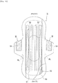
- an absorbent article N such as a sanitary napkin, a panty liner, a vaginal discharge sheet or an incontinence pad, for example, as shown in Fig. 10 , an absorbent article is known in which an absorbent member 52 formed of cotton-like pulp or the like is interposed between a liquid impermeable back sheet 50 formed with a polyethylene sheet, a polyethylene-laminated nonwoven fabric or the like and a liquid permeable front sheet 51 formed with a nonwoven fabric, a porous plastic sheet or the like.
- an absorbent article in which in order to prevent displacement in a fitted state, for example, one or a plurality of strips of adhesive layers 53 are formed on a non-skin contact surface (outer surface), in which on both side portions of a napkin main body in a longitudinal direction, wing-shaped flaps W extending outward are integrally formed and in which adhesive layers 54 are provided on the surfaces (outer surfaces) of the wing-shaped flaps W on the side of the liquid impermeable back sheet 50 (see patent literatures 1 and 2 and the like).
- the absorbent article N is put on a local corresponding part of the underwear 60, the wing-shaped flaps W protruding laterally are protruded outward from the underwear, the wing-shaped flaps W are folded back on return lines RL and are adhered to the outer surface of the crotch portion of the underwear 60 so as to be wrapped around the crotch part of the underwear and thereafter the underwear is fitted to the body.
- patent literature 3 described below discloses an absorbent article in which wing portions are flexibly and easily bent along the side edge of the crotch portion of underwear and can be fixed to the underwear easily and quickly, which includes, in order for the underwear to have excellent antifouling property, an absorbent main body having an absorbing layer and a leak-proof layer and a pair of wing portions provided on both sides of the absorbent main body in an excretory portion opposite portion and in which the shapes of the pair of wing portions are asymmetric forward and backward with respect to a transversal line in a width direction passing the midpoint of the edge portion of a tip end in each of the wing portions.
- WO 2013/047716 A1 discloses that a napkin on which wing-like wings which are fixed in such a manner as to envelop a crotch part of underwear when worn, are formed on both sides of a body part on which an absorption body is disposed between a liquid-permeable surface sheet and a liquid-impermeable rear surface sheet, each wing-like flap has a front side outline that extends outward from the body part, and a rear side outline that extends outward from the bod part.
- the front side outline forms a wavy line due to the repetition of convex sections that protrude to the outside and concave sections that protrude to the inside.
- a straight line that joins the vertex of a convex portion positioned on the very outside, and a connection point where the rear outline of the wing-like flap connects to the body part of the napkin is set at an angle ( ⁇ ) of 60 to 65° with respect to a line in the width direction of the napkin, through which the connection point passes.
- WO 2005/060907 A1 discloses an absorbent article, such as a feminine care product, including a pad component having a liquid permeable top cover, a generally liquid impermeable baffle, and an absorbent structure disposed between the top cover and outer cover.
- Protective wing portions extend laterally outward from lateral sides of the pad component and have dimensions so as to wrap at least partially around the crotch portion of a wearer's undergarment.
- the wing portions extend longitudinally along both sides of a transverse centerline of the pad and have an asymmetric shape with an overlap region disposed forward of the transverse centerline.
- the wing-shaped flaps W can be a significantly effective means in order to achieve the fixation to shorts, when the wing-shaped flaps W are carelessly folded back, only part thereof is folded back, the wing-shaped flaps W cannot be accurately folded back on the return lines RL and the return lines of the wing-shaped flaps are obliquely bent and folded back, with the result that for example, it is disadvantageously impossible to fix the wing-shaped flaps to the shorts.
- the wing portion is formed in a shape which has a pair of front and back edge portions (a front side outline and a back side outline) and an edge portion (a tip end side outline) of the tip end of the wind portion extending from those edge portions, the tip end side outline is formed with a straight line which is substantially parallel to the longitudinal direction of the napkin, and is formed so as to extend, in a connection part to the back side outline, in a direction substantially intersecting a tangential direction of the back side outline.
- the hand when in order to fold the wing portion, an operation of putting a hand along the back side outline from a base end side toward the tip end side is performed, the hand can be moved only within a range of the back side outline and in order to move to the tip end side beyond the range, it is necessary to rapidly change the angle at which the hand is moved, with the result that it is impossible to perform an operation of continuously putting the hand therealong.
- it is difficult to press, with the hand, the tip end side of the wing-shaped flaps, and since the tip end side is not sufficiently fixed, the wing-shaped flaps are peeled from the tip end side so as to be easily separated therefrom.
- a main object of the present invention is to provide an absorbent article in which wing-shaped flaps can be securely fixed to underwear by putting a hand therealong to the tip end of the wing-shaped flaps.
- an absorbent article in which on both side portions of a main body part where an absorbent member (4) is interposed between a liquid permeable front sheet (3) and a liquid impermeable back sheet (2), wing-shaped flaps (W) are formed that are fixed so as to wrap a crotch part of underwear when being fitted, where the wing-shaped flap (W) is formed with a front side outline (10) which is extended outward from the main body part, a back side outline (11) which is extended outward from the main body part and a tip end side outline (12) which connects the front side outline (10) and the back side outline (11), wherein the tip end side outline (12) includes a tip end side outline front portion (12a) which is extended outward from the front side outline (10) and a tip end side outline back portion (12b) which is extended outward from the back side outline (11), an intersection between the tip end side outline front portion (12a) and the tip end side outline back portion (12b) forms
- the planar shape of the wing-shaped flap is the shape in which the tip end side outline connecting the front side outline and the back side outline is included and in which the tip end side outline includes the tip end side outline front portion and the tip end side outline back portion, and the intersection between the tip end side outline front portion and the tip end side outline back portion forms the outermost side end portion in the width direction of the wing-shaped flap and is located on the front side with respect to the center point of the length between the end portion of the front side outline and the end portion of the back side outline in the longitudinal direction of the absorbent article, and when a is a length in the longitudinal direction of the absorbent article between the end portion (A) of the front side outline (10) and the outermost side end portion (B) in the width direction, and when b is a length in the longitudinal direction of the absorbent article between the end portion (C) of the back side outline (11) and the outermost side end portion (B) in the width direction, the outermost side end portion (B) in the width direction is provided at a position where
- a preferred embodiment provides the absorbent article of claim 1 in which an angle ⁇ formed by a straight line connecting the end portion (C) of the back side outline (11) and the outermost side end portion (B) in the width direction of the wing-shaped flap (W) and the back side outline (11) falls within a range of 115° ⁇ ⁇ ⁇ 160°.
- a preferred embodiment provides the absorbent article of claim 1 or 2 wherein the tip end side outline front portion (12a) is formed with an arc having a single radius of curvature, and the tip end side outline back portion (12b) is formed with a combination of arcs having a plurality of radiuses of curvature .
- the tip end side outline back portion is formed with a combination of arcs having a plurality of radiuses of curvature, and thus it is possible to more smoothly put the hand therealong from the back side outline to the tip end side outline back portion when the wing-shaped flap is fixed to the underwear, with the result that the wing-shaped flap is easily fixed to the underwear.
- a preferred embodiment provides the absorbent article of claim 3, wherein the tip end side outline front portion (12a) has a radius of curvature in a range of 10 to 20 mm; the center of curvature thereof is located on a line in the width direction of the absorbent article, the line passing through the outermost side end portion (B) in the width direction of the wing-shaped flap (W); and the tip end side outline back portion (12b) has, in a connection part to the outermost side end portion (B) in the width direction of the wing-shaped flap (W), an arc component whose center of curvature is located on the line in the width direction of the absorbent article, the line passing through the outermost side end portion (B) in the width direction of the wing-shaped flap (W), the arc component having a radius of curvature in a range of 70 to 120 mm.
- the present invention it is possible to securely fix the wing-shaped flap to the underwear by putting the hand therealong to the tip end of the wing-shaped flap.
- a sanitary napkin 1 is formed with a liquid impermeable back sheet 2 which is formed with a polyethylene sheet, a polypropylene sheet or the like, a liquid permeable front sheet 3 which rapidly transmits menstrual blood, vaginal discharge and the like, an absorbent member 4 which is interposed between these sheets 2 and 3 and which is formed of cotton-like pulp, synthetic pulp or the like, crepe paper 5 which surrounds the absorbent member 4 in order to retain the shape of the absorbent member 4 and to enhance diffusivity, a second sheet 6 which is interposed between the liquid permeable front sheet 3 and the crepe paper 5 and which is formed of a hydrophilic nonwoven fabric and side nonwoven fabrics 7 which are formed on both side portions of the surface along a longitudinal direction.
- the absorbent member 4 in the upper and lower end edge portions thereof, the outer edge portions of the liquid impermeable back sheet 2 and the liquid permeable front sheet 3 are joined by an adhesive such as a hot melt or an adhesive means such as a heat seal, and in both side edge portions thereof, the liquid impermeable back sheet 2 and the side nonwoven fabrics 7 extending laterally as compared with the absorbent member 4 are joined by an adhesive such as a hot melt or an adhesive means such as a heat seal.
- an adhesive such as a hot melt or an adhesive means such as a heat seal
- the structure of the sanitary napkin 1 will further be described in detail below.
- a sheet member such as an olefin-based resin sheet such as polyethylene or polypropylene, which has at least a water shielding property is used, and moreover, a laminate nonwoven fabric in which a nonwoven fabric is stacked in layers on a polyethylene sheet or the like, a nonwoven fabric sheet in which a waterproof film is interposed to practically acquire liquid-impermeability (in this case, the waterproof film and the nonwoven fabric form the liquid impermeable back sheet) and the like can be used.
- a sheet which has moisture permeability tends to be used.
- the water shielding and moisture permeable sheet member is a microporous sheet that is obtained by melting and kneading an inorganic filler in an olefin-based resin such as polyethylene or polypropylene to mold a sheet and stretching it in a uniaxial or biaxial direction.
- an olefin-based resin such as polyethylene or polypropylene
- a porous or nonporous nonwoven fabric, a porous plastic sheet or the like is preferably used.
- the material fiber of the nonwoven fabric can include the synthetic fibers of olefins such as polyethylene and polypropylene, polyesters, polyamides and the like, regenerated fibers such as rayon and cupra and natural fibers such as cotton, and nonwoven fabrics obtained by appropriate processing methods such as a span lace method, a span bond method, a thermal bond method, a melt-blown method and a needle punch method can be used.
- the span lace method is excellent in flexibility and drapability
- the thermal bond method is excellent in bulkiness and softness.
- Various types of embosses are provided from the side of the upper surface of the liquid permeable front sheet 3, thus the retention of a body fluid is facilitated and the efficiency of absorption is enhanced, with the result that it is preferable to prevent side leakage.
- the absorbent member 4 interposed between the liquid impermeable back sheet 2 and the liquid permeable front sheet 3 is formed with, for example, fluff-shaped pulp and a water-absorbent polymer.
- the water-absorbent polymer is mixed in the pulp of the absorbent member as, for example, a granular powder.
- the pulp described above include chemical pulps which are obtained from wood and pulps which are formed of cellulose fibers such as dissolving pulp and artificial cellulose fibers such as rayon and acetate, and as compared with hardwood pulp, softwood pulp having a long fiber length is preferably used in terms of function and price.
- the crepe paper 5 surrounding the absorbent member 4 is provided as this example, the crepe paper 5 is consequently interposed between the liquid permeable front sheet 3 and the absorbent member 4, and thus a body fluid is rapidly diffused by the crepe paper 5 excellent in absorbability and the menstrual blood thereof and the like are prevented from being folded back.
- Examples of the second sheet 6 formed with a hydrophilic nonwoven fabric interposed between the liquid permeable front sheet 3 and the crepe paper 5 can include the synthetic fibers of olefins such as polyethylene and polypropylene, polyesters, polyamides and the like, regenerated fibers such as rayon and cupra and natural fibers such as cotton, and nonwoven fabrics obtained by appropriate processing methods such as a span lace method, a span bond method, a thermal bond method, a melt-blown method and a needle punch method can be used.
- a method of using together a compound having a hydrophilic group in the manufacturing process of a synthetic fiber for example, an oxidation product of polyethylene glycol to perform polymerization, a method of performing processing with a metal salt such as stannic chloride, partially dissolving the surface to have porosity and depositing a hydroxide of the metal or the like, the synthetic fiber is swollen or made porous, with the result that it is possible to provide hydrophilicity by the application of capillarity.
- the side nonwoven fabrics 7 are provided, and parts of the side nonwoven fabrics 7 are extended laterally, and the wing-shaped flaps W are formed with parts of liquid impermeable back sheet 2 likewise extended laterally.
- the wing-shaped flaps W will be described in detail later.
- a water-repellent nonwoven fabric or a hydrophilic nonwoven fabric can be used.
- a water-repellent nonwoven fabric coated with a silicon-based, paraffin-based or alkyl chromic chloride-based water repellent or the like is preferably used.
- a hydrophilic nonwoven fabric is used in which with a method of using together a compound having a hydrophilic group in the manufacturing process of a synthetic fiber, for example, an oxidation product of polyethylene glycol to perform polymerization, a method of performing processing with a metal salt such as stannic chloride, partially dissolving the surface to have porosity and depositing a hydroxide of the metal or the like, the synthetic fiber is swollen or made porous and thus hydrophilicity is provided by the application of capillarity.
- a metal salt such as stannic chloride
- a plurality of strips of, that is, in the example shown in the figure, three strips of main body displacement prevention adhesive layers 8 are formed by an appropriate coating pattern in order to perform the fixation to the underwear, and these main body displacement prevention adhesive layers 8 are covered with an unillustrated main body separating material.
- wing displacement prevention adhesive layers 9 are formed, and the wing displacement prevention adhesive layers 9 are covered with an unillustrated wing separating material.
- the main body separating material and the wing separating material arranged in a transverse direction are joined at an intersection portion, and thus the separating materials can be removed by one separation operation.
- the wing-shaped flaps W may be folded back to the side of the liquid permeable front sheet 3, that is, may be subjected to so-called belly folding or may be folded back to the side of the liquid impermeable back sheet 2, that is, may be subjected to so-called back folding.
- the separating material covering the wing displacement prevention adhesive layers 9 instead of the one separating material, the separating material may be separated into left and right portions.
- separating material paper or plastic sheet can be used in which a contact surface to the displacement prevention adhesive layers 8 and 9 is coated with or coated by spraying with a mold release processing solution such as a silicone resin, a fluorine resin or a tetrafluoride ethylene resin and is subjected to mold release processing.
- a mold release processing solution such as a silicone resin, a fluorine resin or a tetrafluoride ethylene resin and is subjected to mold release processing.
- an adhesive whose main component is any one of a styrene-based polymer, a tackifier and a plasticizer is preferably used.
- the styrene-based polymer include a styrene-ethylene-butylene-styrene block copolymer, a styrene-butylene-styrene block copolymer and a styrene-isobutylene-styrene copolymer, and only one type thereof may be used or a polymer blend of two or more types may be used.
- the styrene-ethylene-butylene-styrene block copolymer is preferable.
- a tackifier and a plasticizer which are solid at room temperature can be preferably used, and examples of the tackifier include a C5-based petroleum resin, a C9-based petroleum resin, a dicyclopentadiene-based petroleum resin, a rosin-based petroleum resin, a polyterpene resin and a terpene phenol resin, and examples of the plasticizer include monomeric plasticizers such as tricresyl phosphoric acid, dibutyl phthalate and dioctyl phthalate and polymeric plasticizers such as a vinyl polymer and polyester.
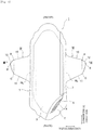
- the wing-shaped flap W forms an outline shape that is formed with a front side outline 10 which is extended outward from the main body part, a back side outline 11 which is extended outward from the main body part and a tip end side outline 12 which connects the front side outline 10 and the back side outline 11.
- the tip end side outline 12 is formed with a tip end side outline front portion 12a which is extended outward from an end portion A of the front side outline 10 and a tip end side outline back portion 12b which is extended outward from an end portion C of the back side outline 11. As shown in Fig.
- the end portion A of the front side outline 10 and the end portion C of the back side outline 11 indicate, when the front side outline 10 or the back side outline 11 is formed with a straight line, a part which is separated from the straight line, indicate, when the front side outline 10 or the back side outline 11 is formed with a wavy line made by a combination of a convex curve and a concave curve, a part which is separated from a tangent connecting the apex portions of the convex curve, and indicate, when the front side outline 10 or the back side outline 11 is formed with a curve, a part where a curve is started whose radius of curvature is rapidly decreased or whose center of curvature's position is rapidly changed.
- An intersection B between the tip end side outline front portion 12a and the tip end side outline back portion 12b forms an outermost side end portion in the width direction of the wing-shaped flap W.
- the outermost side end portion in the width direction of the wing-shaped flap W refers to a tip end part in the width direction where the outline of the wing-shaped flap W is tangent to a line M in the longitudinal direction of the napkin on the outermost.
- the intersection B is located on the front side of the napkin as compared with the center point (K/2) of a length K in the longitudinal direction of the napkin between the end portion A of the front side outline 10 and the end portion C of the back side outline 11.
- a ⁇ b preferably holds true, and the intersection B is more preferably provided in a position where a : b is about 1 : 1.5 to 1 : 3 .
- an outer bulging portion is formed which is displaced to the front side of the napkin with respect to the center of the line AC and in which an outer end portion B in the width direction of the wing-shaped flap W is its apex.
- the outer bulging portion has a triangle ABC as a basic form, and each of the side AB and the side BC is formed with a curve, a straight line or a combination thereof. In the example shown in the figure, the each of the side AB and the side BC is formed with a curve which is bulged outward.
- the outer bulging portion is formed, and thus on the outer side with respect to the end portion C of the back side outline 11, the tip end side outline back portion 12b extending outward and obliquely forward is provided toward an outer side end portion B in the width direction of the wing-shaped flap W.
- the wing-shaped flap W is shaped as described above, and thus when the wing-shaped flap W is folded back at the time of the fitting of the napkin, it is possible to fold the wing-shaped flap W by putting a hand along substantially the entire width of the wing-shaped flap W, with the result that even the tip end side can be securely fixed to the underwear. Specifically, as will be described in detail later, although when the wing-shaped flap W is folded back, as shown in Fig.
- an operation of moving the hand is performed by putting the back side outline 11 of the wing-shaped flap W from a base end side along the direction of the tip end side, in the case of a conventional wing-shaped flap W having an isosceles trapezoid shape, the length of the back side outline from the wing base end side to the tip end side is short, furthermore the tip end side outline is formed with a straight line substantially parallel to the longitudinal direction of the napkin and thus such a structural disadvantage is formed that it is difficult to perform the operation of putting the hand therealong to the tip end side outline.
- the wing-shaped flap cannot be accurately folded back in a proper return position, and that the wing-shaped flap cannot be securely fitted to the underwear.
- the tip end of the wing-shaped flap along which it is difficult to put the hand is disadvantageously and easily peeled.
- wing-shaped flap W when the wing-shaped flap W is folded back with the hand while an operation of moving the hand forward along the back side outline 11 and the tip end side outline back portion 12b is being performed, the wing-shaped flap can be accurately fitted in a proper state, the hand can be put therealong to the tip end of the wing-shaped flap and the wing-shaped flap is formed in a wing shape in which the wing-shaped flap can be securely fitted to the underwear.
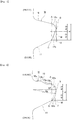
- an angle ⁇ formed by a straight line BC (the tip end side outline back portion 12b) connecting the end portion C of the back side outline 11 and the outermost side end portion B in the width direction of the wing-shaped flap W and the back side outline 11 preferably falls within about a range of 115° ⁇ ⁇ ⁇ 160°.
- the tip end side outline back portion 12b is provided such that the angle ⁇ falls within this angular range, and thus the wing-shaped flap is easily fitted by putting the hand therealong continuously from the back side outline 11 to the tip end side outline back portion 12b.
- the tip end side outline front portion 12a and the tip end side outline back portion 12b can be formed with a curved line which is bulged outward.
- the tip end side outline back portion 12b is formed with the curved line, and thus the outline from the end portion C of the back side outline 11 to the outermost side end portion B in the width direction of the wing-shaped flap W is connected by a smooth curve, and thus it is possible to smoothly put the hand therealong from the back side outline 11 to outermost side end portion B in the width direction of the wing-shaped flap W, with the result that the fitting operation is easily performed.
- the tip end side outline front portion 12a is formed with the curved line, and thus the part from the end portion A of the front side outline 10 to the outermost side end portion B in the width direction of the wing-shaped flap W is connected by the smooth curve, with the result that it is possible to prevent this part from being separated.
- the back side outline 11 is preferably formed with a straight line or a curve slightly bulged outward so that the hand can be easily put therealong when the wing-shaped flap W is folded back. If the back side outline 11 is formed with a wavy line or a curve significantly bulged outward, this is not desirable because when the hand is moved along the back side outline 11, a finger is caught in the projections and recesses of the wavy line or the curve.
- the tip end side outline back portion 12b can be formed with a straight line. In this way, the hand is easily and linearly put along the tip end side outline back portion 12b.
- the connection part (C) between the tip end side outline back portion 12b and the back side outline 11 the connection is preferably made with a gentle curve such that a corner portion is prevented from being formed.
- the front side outline 10 can be formed with a wavy line, a curve or a combination thereof.
- the front side outline 10 is formed in such a shape, and thus as compared with a case where the front side outline 10 is formed with a straight line, the rigidity of the front side of the wing-shaped flap W is enhanced, and thus when the wing-shaped flap W is folded back, it can be fitted without a wrinkle and a crease.
- the wavy line is formed with a combination of convex curves 10b and concave curves 10a, and the convex curves 10b and the concave curves 10a are alternately arranged, and thus one or more of convex portions and one or more of concave portions are formed with respect to a line passing through the center portion of the convex curve 10b and the concave curve 10a.
- the curve is preferably a curve which is bulged outward but may be a curve which is bulged inward.
- the tip end side outline front portion 12a when the tip end side outline front portion 12a is formed with a curved line which is bulged outward, the front side outline 10 is formed with a wavy line, a curve or a combination thereof, and thus the part from the front side outline 10 to the tip end side outline front portion 12a is provided in a shape in which the wavy line or the curve is continuous, with the result that an effect produced by forming the front side outline 10 with the wavy line or the like is more achieved.
- the front side outline 10 is formed with a wavy line made of the convex curves 10b and the concave curves 10a, the concave curve 10a is provided so as to be extended from a curve which is tangent to the side edge of the main body part, on the outer side thereof, the convex curve 10b and the concave curve 10a are provided and furthermore an arc that is bulged outward of the tip end side outline front portion 12a is started so as to be extended from the apex portion (A) of the convex curve 10b provided outward thereof and is extended to a point B.
- the tip end side outline front portion 12a is formed with an arc having a single radius of curvature Ra, and the center of curvature thereof is located on a line of the napkin in the width direction passing through the point B.
- the radius of curvature Ra is preferably about 10 to 20 mm.
- the back side outline 11 is formed with a straight line connected between the side edge of the main body part and a curve, the end portion C serves as a boundary and the curve which is bulged outward of the tip end side outline back portion 12b is started and is extended to the point B.
- the tip end side outline back portion 12b is formed with a combination of arcs having a plurality of radiuses of curvature, and has, in a connection part to the point B, an arc component whose center of curvature is located on the line of the napkin in the width direction passing through the point B and which has a radius of curvature Rb.
- the radius of curvature Rb is preferably about 70 to 120 mm.
- the shape of the wing-shaped flap W is set such that an angle ⁇ formed by a line of the sanitary napkin 1 in the width direction and the back side outline 11 is greater than an angle ⁇ formed by the line of the sanitary napkin 1 in the width direction and the front side outline 10, and the center of gravity 13 in the wing-shaped flap W is displaced to the front side by ⁇ S with respect to a center point 14 of a joint line 15 of the root and the main body part of the wing-shaped flap W.
- the front side outline 10, the back side outline 11 and the tip end side outline 12 does not need to be formed with a straight line, and may be formed with a wavy line, a curve or a combination thereof. In this case, as the angles ⁇ and ⁇ , gradients formed by the center lines of these wavy or curve outlines are preferably taken.
- the angle ⁇ formed by the line of the sanitary napkin 1 in the width direction and the front side outline 10 is set at about 0 to 20°
- the angle ⁇ formed by the line of the sanitary napkin 1 in the width direction and the back side outline 11 is set at about 20 to 45°.
- an angle difference between the angle ⁇ formed by the line of the sanitary napkin 1 in the width direction and the front side outline 10 and the angle ⁇ formed by the line of the sanitary napkin 1 in the width direction and the back side outline 11 is preferably set equal to or more than 25°.
- the angle difference is equal to or more than 25°, a sufficient eccentric distance ⁇ S can be acquired, and even when as will be described later, the wing-shaped flap W is folded back by the hand while an operation of moving the hand to the front side is being performed, the wing-shaped flap can be securely fitted in a proper state.
- the wing-shaped flap W is formed so as to have the outline shape described above, and thus for example, advantages can be produced in which failures such as the adhesion of adhesives and erroneous adhesion are prevented from occurring in the wing-shaped flap W, in which it is possible to easily and accurately fold back and adhere the wing-shaped flap in a proper return position and in which it is possible to securely fit the wing-shaped flap W to the underwear by putting the hand therealong to the tip end of the wing-shaped flap W.
- This point will be further described in detail by comparison with the conventional wing-shaped flap W (see Fig. 10 ) having an isosceles trapezoid shape.
- the conventional wing-shaped flap W having an isosceles trapezoid shape has a structure in which the fitting cannot be satisfactorily performed unless the wing-shaped flap is folded back in a direction immediately therebelow from a state where the hand is put on both sides of the napkin.
- a failure occurs in which since the position of the fitting is located on the front side with respect to the body, an operation ( Fig.
- the wing shape is adopted such that even when the wing-shaped flap W is folded back by the hand while the operation of moving the hand to the front side is being performed, the wing-shaped flap can be securely fitted in a proper state and that it is possible to put the hand therealong to the tip end of the wing-shaped flap W.
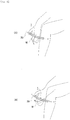
- Fig. 9(A) is a diagram showing the mechanism of an acting force when the conventional wing-shaped flap W having an isosceles trapezoid shape is returned back.
- the wing-shaped flap W is folded back by the hand while the operation of moving the hand to the front side is being performed, when it is assumed that a load applied downward from the back side outline of the wing-shaped flap W to the tip end side acts and that a concentrated load ⁇ P is obtained by collecting the load distribution thereof, the base point of a moment produced by the concentrated load ⁇ P is the center point 14 of the joint line 15 in the wing-shaped flap W, a twist occurs when the wing-shaped flap W is folded back and a return line 16 gradually travelling from the base end of the back side outline 11 is inclined outward.
- the return line 16 reliably and gradually travels from the base end of the back side outline 11 toward the front side.
- the length L of protrusion of the wing-shaped flap W is set at 40 to 50 mm, and is preferably set longer than the half of the crotch width of the shorts 20.
- the length L is set longer than the half of the crotch width of the shorts 20, and thus it is possible to securely fix the shorts.
- the wing displacement prevention adhesive layer 9 provided on the side of the back surface of the wing-shaped flap W is formed in a shape in which in the width of the napkin 1 in the longitudinal direction, a tip end side SL is narrower than a base end side NL, and specifically, is formed in a substantially triangular shape, a substantially isosceles shape or an unequal isosceles shape. In this way, when the wing-shaped flap W is folded back, it is unlikely that the adhesion of adhesives and erroneous adhesion occur.
- sanitary napkin 1: sanitary napkin, 2: liquid impermeable back sheet, 3: liquid permeable front sheet, 4: absorbent member, 5: crepe paper, 6: second sheet.
Description
- The present invention relates to an absorbent article provided with wing-shaped flaps which are used so as to be wrapped around the crotch part of underwear when the absorbent article is fixed to the underwear.
- Conventionally, as an absorbent article N such as a sanitary napkin, a panty liner, a vaginal discharge sheet or an incontinence pad, for example, as shown in
Fig. 10 , an absorbent article is known in which anabsorbent member 52 formed of cotton-like pulp or the like is interposed between a liquidimpermeable back sheet 50 formed with a polyethylene sheet, a polyethylene-laminated nonwoven fabric or the like and a liquidpermeable front sheet 51 formed with a nonwoven fabric, a porous plastic sheet or the like. - As this type of absorbent article N, an absorbent article is present in which in order to prevent displacement in a fitted state, for example, one or a plurality of strips of
adhesive layers 53 are formed on a non-skin contact surface (outer surface), in which on both side portions of a napkin main body in a longitudinal direction, wing-shaped flaps W extending outward are integrally formed and in whichadhesive layers 54 are provided on the surfaces (outer surfaces) of the wing-shaped flaps W on the side of the liquid impermeable back sheet 50 (seepatent literatures - In order to fix the absorbent article N to
underwear 60, as shown inFig. 11 , the absorbent article N is put on a local corresponding part of theunderwear 60, the wing-shaped flaps W protruding laterally are protruded outward from the underwear, the wing-shaped flaps W are folded back on return lines RL and are adhered to the outer surface of the crotch portion of theunderwear 60 so as to be wrapped around the crotch part of the underwear and thereafter the underwear is fitted to the body. - Many improvements have been performed on this type of absorbent article N, and for example,
patent literature 3 described below discloses an absorbent article in which wing portions are flexibly and easily bent along the side edge of the crotch portion of underwear and can be fixed to the underwear easily and quickly, which includes, in order for the underwear to have excellent antifouling property, an absorbent main body having an absorbing layer and a leak-proof layer and a pair of wing portions provided on both sides of the absorbent main body in an excretory portion opposite portion and in which the shapes of the pair of wing portions are asymmetric forward and backward with respect to a transversal line in a width direction passing the midpoint of the edge portion of a tip end in each of the wing portions. -
- Patent Literature 1: Japanese Unexamined Patent Application Publication No.
2003-111799 - Patent Literature 2: Japanese Unexamined Patent Application Publication No.
2004-113590 - Patent Literature 3: Japanese Unexamined Patent Application Publication No.
2008-12098 -
WO 2013/047716 A1 discloses that a napkin on which wing-like wings which are fixed in such a manner as to envelop a crotch part of underwear when worn, are formed on both sides of a body part on which an absorption body is disposed between a liquid-permeable surface sheet and a liquid-impermeable rear surface sheet, each wing-like flap has a front side outline that extends outward from the body part, and a rear side outline that extends outward from the bod part. The front side outline forms a wavy line due to the repetition of convex sections that protrude to the outside and concave sections that protrude to the inside. A straight line that joins the vertex of a convex portion positioned on the very outside, and a connection point where the rear outline of the wing-like flap connects to the body part of the napkin is set at an angle (α) of 60 to 65° with respect to a line in the width direction of the napkin, through which the connection point passes. -
WO 2005/060907 A1 discloses an absorbent article, such as a feminine care product, including a pad component having a liquid permeable top cover, a generally liquid impermeable baffle, and an absorbent structure disposed between the top cover and outer cover. Protective wing portions extend laterally outward from lateral sides of the pad component and have dimensions so as to wrap at least partially around the crotch portion of a wearer's undergarment. The wing portions extend longitudinally along both sides of a transverse centerline of the pad and have an asymmetric shape with an overlap region disposed forward of the transverse centerline. - Although the wing-shaped flaps W can be a significantly effective means in order to achieve the fixation to shorts, when the wing-shaped flaps W are carelessly folded back, only part thereof is folded back, the wing-shaped flaps W cannot be accurately folded back on the return lines RL and the return lines of the wing-shaped flaps are obliquely bent and folded back, with the result that for example, it is disadvantageously impossible to fix the wing-shaped flaps to the shorts.
- Although in the absorbent article disclosed in
patent literature 3, the wing portion is formed in a shape which has a pair of front and back edge portions (a front side outline and a back side outline) and an edge portion (a tip end side outline) of the tip end of the wind portion extending from those edge portions, the tip end side outline is formed with a straight line which is substantially parallel to the longitudinal direction of the napkin, and is formed so as to extend, in a connection part to the back side outline, in a direction substantially intersecting a tangential direction of the back side outline. Hence, when in order to fold the wing portion, an operation of putting a hand along the back side outline from a base end side toward the tip end side is performed, the hand can be moved only within a range of the back side outline and in order to move to the tip end side beyond the range, it is necessary to rapidly change the angle at which the hand is moved, with the result that it is impossible to perform an operation of continuously putting the hand therealong. Hence, disadvantageously, it is difficult to press, with the hand, the tip end side of the wing-shaped flaps, and since the tip end side is not sufficiently fixed, the wing-shaped flaps are peeled from the tip end side so as to be easily separated therefrom. - Hence, a main object of the present invention is to provide an absorbent article in which wing-shaped flaps can be securely fixed to underwear by putting a hand therealong to the tip end of the wing-shaped flaps.
- In order to solve the problem described above, according to the present invention, there is provided an absorbent article in which on both side portions of a main body part where an absorbent member (4) is interposed between a liquid permeable front sheet (3) and a liquid impermeable back sheet (2), wing-shaped flaps (W) are formed that are fixed so as to wrap a crotch part of underwear when being fitted, where the wing-shaped flap (W) is formed with a front side outline (10) which is extended outward from the main body part, a back side outline (11) which is extended outward from the main body part and a tip end side outline (12) which connects the front side outline (10) and the back side outline (11), wherein the tip end side outline (12) includes a tip end side outline front portion (12a) which is extended outward from the front side outline (10) and a tip end side outline back portion (12b) which is extended outward from the back side outline (11), an intersection between the tip end side outline front portion (12a) and the tip end side outline back portion (12b) forms an outermost side end portion (B) in a width direction of the wing-shaped flap (W) and is located on a front side with respect to a center point (k/2) of a length between an end portion (A) of the front side outline (10) and an end portion (C) of the back side outline (11) in a longitudinal direction of the absorbent article, and when a is a length in the longitudinal direction of the absorbent article between the end portion (A) of the front side outline (10) and the outermost side end portion (B) in the width direction, and when b is a length in the longitudinal direction of the absorbent article between the end portion (C) of the back side outline (11) and the outermost side end portion (B) in the width direction, the outermost side end portion (B) in the width direction is provided at a position where a : b is 1 : 1.5 to 1 : 3,
wherein the front side outline (10) is formed with a wavy line made of convex curves (10b) and concave curves (10a); a section from an apex portion of the convex curve provided outermost to the outermost side end portion (B) in the width direction of the wing-shaped flap (W) is the tip end side outline front portion (12a); and the tip end side outline front portion (12a) is formed with a curved line which is bulged outward, and
wherein the back side outline (11) is formed with a straight line; a section from the end portion of the back side outline (11) to the outermost side end portion (B) in the width direction of the wing-shaped flap (W) is the tip end side outline back portion (12b); and the tip end side outline back portion (12b) is formed with a curved line which is bulged outward. - According to
claim 1, the planar shape of the wing-shaped flap is the shape in which the tip end side outline connecting the front side outline and the back side outline is included and in which the tip end side outline includes the tip end side outline front portion and the tip end side outline back portion, and the intersection between the tip end side outline front portion and the tip end side outline back portion forms the outermost side end portion in the width direction of the wing-shaped flap and is located on the front side with respect to the center point of the length between the end portion of the front side outline and the end portion of the back side outline in the longitudinal direction of the absorbent article, and when a is a length in the longitudinal direction of the absorbent article between the end portion (A) of the front side outline (10) and the outermost side end portion (B) in the width direction, and when b is a length in the longitudinal direction of the absorbent article between the end portion (C) of the back side outline (11) and the outermost side end portion (B) in the width direction, the outermost side end portion (B) in the width direction is provided at a position where a : b is 1 : 1.5 to 1 : 3,
wherein the front side outline (10) is formed with a wavy line made of convex curves (10b) and concave curves (10a); a section from an apex portion of the convex curve provided outermost to the outermost side end portion (B) in the width direction of the wing-shaped flap (W) is the tip end side outline front portion (12a); and the tip end side outline front portion (12a) is formed with a curved line which is bulged outward, and
wherein the back side outline (11) is formed with a straight line; a section from the end portion of the back side outline (11) to the outermost side end portion (B) in the width direction of the wing-shaped flap (W) is the tip end side outline back portion (12b); and the tip end side outline back portion (12b) is formed with a curved line which is bulged outward. - In such a shape, as will be described in detail later, when the wing-shaped flap is folded back over the substantially entire width of the wing-shaped flap from the back side outline to the tip end side outline, it is easy to fold back the wing-shaped flap by continuously putting a hand therealong to the outermost side end portion in the width direction, with the result that it is possible to securely fix the tip end side of the wing-shaped flap to the underwear.
- A preferred embodiment provides the absorbent article of
claim 1 in which an angle θ formed by a straight line connecting the end portion (C) of the back side outline (11) and the outermost side end portion (B) in the width direction of the wing-shaped flap (W) and the back side outline (11) falls within a range of 115° ≤ θ ≤ 160°. - A preferred embodiment provides the absorbent article of
claim - According to
claim 3, the tip end side outline back portion is formed with a combination of arcs having a plurality of radiuses of curvature, and thus it is possible to more smoothly put the hand therealong from the back side outline to the tip end side outline back portion when the wing-shaped flap is fixed to the underwear, with the result that the wing-shaped flap is easily fixed to the underwear. - A preferred embodiment provides the absorbent article of
claim 3, wherein the tip end side outline front portion (12a) has a radius of curvature in a range of 10 to 20 mm; the center of curvature thereof is located on a line in the width direction of the absorbent article, the line passing through the outermost side end portion (B) in the width direction of the wing-shaped flap (W); and the tip end side outline back portion (12b) has, in a connection part to the outermost side end portion (B) in the width direction of the wing-shaped flap (W), an arc component whose center of curvature is located on the line in the width direction of the absorbent article, the line passing through the outermost side end portion (B) in the width direction of the wing-shaped flap (W), the arc component having a radius of curvature in a range of 70 to 120 mm. - As described above in detail, in the present invention, it is possible to securely fix the wing-shaped flap to the underwear by putting the hand therealong to the tip end of the wing-shaped flap.
-
- [
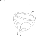
Fig. 1 ] A partially broken development view of asanitary napkin 1 according to the present invention; - [
Fig. 2 ] A back view thereof; - [
Fig. 3 ] A diagram viewing from the arrow direction of line III-III shown inFig. 1 ; - [
Fig. 4 ] A plan view of an enlarged main portion of a wing-shaped flap W; - [
Fig. 5 ] A plan view showing a variation of the wing-shaped flaps W according to the present invention; - [
Fig. 6 ] A plan view showing a variation of the wing-shaped flaps W according to the present invention; - [
Fig. 7 ] A schematic view showing the planar shape of the wing-shaped flap W; - [
Fig. 8] Fig. 8(A) shows a procedure for fitting the napkin in the case of a conventional wing-shaped flap; andFig. 8(B) shows a procedure for fitting the napkin in the case of the wing-shaped flap according to the present invention; - [
Fig. 9] Fig. 9(A) shows a mechanism of an acting force when the wing-shaped flap W is folded back in the case of a conventional wing-shaped flap; andFig. 9(B) shows a mechanism of an acting force when the wing-shaped flap W is folded back in the case of the wing-shaped flap according to the present invention; - [
Fig. 10 ] A development view of a conventional sanitary napkin N; and - [
Fig. 11 ] A diagram showing a state in which it is fitted. - An embodiment of the present invention will be described in detail below with reference to drawings.
- As shown in
Figs. 1 to 3 , asanitary napkin 1 according to the present invention is formed with a liquidimpermeable back sheet 2 which is formed with a polyethylene sheet, a polypropylene sheet or the like, a liquidpermeable front sheet 3 which rapidly transmits menstrual blood, vaginal discharge and the like, anabsorbent member 4 which is interposed between thesesheets crepe paper 5 which surrounds theabsorbent member 4 in order to retain the shape of theabsorbent member 4 and to enhance diffusivity, asecond sheet 6 which is interposed between the liquidpermeable front sheet 3 and thecrepe paper 5 and which is formed of a hydrophilic nonwoven fabric and sidenonwoven fabrics 7 which are formed on both side portions of the surface along a longitudinal direction. Around theabsorbent member 4, in the upper and lower end edge portions thereof, the outer edge portions of the liquidimpermeable back sheet 2 and the liquidpermeable front sheet 3 are joined by an adhesive such as a hot melt or an adhesive means such as a heat seal, and in both side edge portions thereof, the liquidimpermeable back sheet 2 and the sidenonwoven fabrics 7 extending laterally as compared with theabsorbent member 4 are joined by an adhesive such as a hot melt or an adhesive means such as a heat seal. - The structure of the
sanitary napkin 1 will further be described in detail below. - As the liquid
impermeable back sheet 2, a sheet member, such as an olefin-based resin sheet such as polyethylene or polypropylene, which has at least a water shielding property is used, and moreover, a laminate nonwoven fabric in which a nonwoven fabric is stacked in layers on a polyethylene sheet or the like, a nonwoven fabric sheet in which a waterproof film is interposed to practically acquire liquid-impermeability (in this case, the waterproof film and the nonwoven fabric form the liquid impermeable back sheet) and the like can be used. In recent years, in terms of stuffiness prevention, a sheet which has moisture permeability tends to be used. The water shielding and moisture permeable sheet member is a microporous sheet that is obtained by melting and kneading an inorganic filler in an olefin-based resin such as polyethylene or polypropylene to mold a sheet and stretching it in a uniaxial or biaxial direction. - As the liquid
permeable front sheet 3, a porous or nonporous nonwoven fabric, a porous plastic sheet or the like is preferably used. Examples of the material fiber of the nonwoven fabric can include the synthetic fibers of olefins such as polyethylene and polypropylene, polyesters, polyamides and the like, regenerated fibers such as rayon and cupra and natural fibers such as cotton, and nonwoven fabrics obtained by appropriate processing methods such as a span lace method, a span bond method, a thermal bond method, a melt-blown method and a needle punch method can be used. Among these processing methods, the span lace method is excellent in flexibility and drapability, and the thermal bond method is excellent in bulkiness and softness. Various types of embosses are provided from the side of the upper surface of the liquidpermeable front sheet 3, thus the retention of a body fluid is facilitated and the efficiency of absorption is enhanced, with the result that it is preferable to prevent side leakage. - The
absorbent member 4 interposed between the liquidimpermeable back sheet 2 and the liquidpermeable front sheet 3 is formed with, for example, fluff-shaped pulp and a water-absorbent polymer. The water-absorbent polymer is mixed in the pulp of the absorbent member as, for example, a granular powder. Examples of the pulp described above include chemical pulps which are obtained from wood and pulps which are formed of cellulose fibers such as dissolving pulp and artificial cellulose fibers such as rayon and acetate, and as compared with hardwood pulp, softwood pulp having a long fiber length is preferably used in terms of function and price. When thecrepe paper 5 surrounding theabsorbent member 4 is provided as this example, thecrepe paper 5 is consequently interposed between the liquidpermeable front sheet 3 and theabsorbent member 4, and thus a body fluid is rapidly diffused by thecrepe paper 5 excellent in absorbability and the menstrual blood thereof and the like are prevented from being folded back. - Examples of the
second sheet 6 formed with a hydrophilic nonwoven fabric interposed between the liquidpermeable front sheet 3 and thecrepe paper 5 can include the synthetic fibers of olefins such as polyethylene and polypropylene, polyesters, polyamides and the like, regenerated fibers such as rayon and cupra and natural fibers such as cotton, and nonwoven fabrics obtained by appropriate processing methods such as a span lace method, a span bond method, a thermal bond method, a melt-blown method and a needle punch method can be used. In order to provide hydrophilicity, with a method of using together a compound having a hydrophilic group in the manufacturing process of a synthetic fiber, for example, an oxidation product of polyethylene glycol to perform polymerization, a method of performing processing with a metal salt such as stannic chloride, partially dissolving the surface to have porosity and depositing a hydroxide of the metal or the like, the synthetic fiber is swollen or made porous, with the result that it is possible to provide hydrophilicity by the application of capillarity. - On the other hand, on both side portions on the side of the surface of the
sanitary napkin 1, along the longitudinal direction and over the substantially entire length of thenapkin 1, theside nonwoven fabrics 7 are provided, and parts of theside nonwoven fabrics 7 are extended laterally, and the wing-shaped flaps W are formed with parts of liquidimpermeable back sheet 2 likewise extended laterally. The wing-shaped flaps W will be described in detail later. - As the side
nonwoven fabric 7, from the viewpoint of a function considered to be important, a water-repellent nonwoven fabric or a hydrophilic nonwoven fabric can be used. For example, when the function of preventing the osmosis of menstrual blood, vaginal discharge and the like or enhancing its texture is considered to be important, a water-repellent nonwoven fabric coated with a silicon-based, paraffin-based or alkyl chromic chloride-based water repellent or the like is preferably used. When the absorbability of menstrual blood and the like in the wing-shaped flaps W is considered to be important, for example, a hydrophilic nonwoven fabric is used in which with a method of using together a compound having a hydrophilic group in the manufacturing process of a synthetic fiber, for example, an oxidation product of polyethylene glycol to perform polymerization, a method of performing processing with a metal salt such as stannic chloride, partially dissolving the surface to have porosity and depositing a hydroxide of the metal or the like, the synthetic fiber is swollen or made porous and thus hydrophilicity is provided by the application of capillarity. - As shown in
Fig. 2 , on the non-skin contact surface of a main body part where theabsorbent member 4 is interposed between the liquidpermeable front sheet 3 and the liquidimpermeable back sheet 2, a plurality of strips of, that is, in the example shown in the figure, three strips of main body displacement preventionadhesive layers 8 are formed by an appropriate coating pattern in order to perform the fixation to the underwear, and these main body displacement preventionadhesive layers 8 are covered with an unillustrated main body separating material. On the surfaces of the wing-shaped flaps W on the side of the liquidimpermeable back sheet 2, wing displacement preventionadhesive layers 9 are formed, and the wing displacement preventionadhesive layers 9 are covered with an unillustrated wing separating material. Preferably, with respect to the separating materials, the main body separating material and the wing separating material arranged in a transverse direction are joined at an intersection portion, and thus the separating materials can be removed by one separation operation. In an individually packed state, the wing-shaped flaps W may be folded back to the side of the liquidpermeable front sheet 3, that is, may be subjected to so-called belly folding or may be folded back to the side of the liquidimpermeable back sheet 2, that is, may be subjected to so-called back folding. As the separating material covering the wing displacement preventionadhesive layers 9, instead of the one separating material, the separating material may be separated into left and right portions. - As the separating material, paper or plastic sheet can be used in which a contact surface to the displacement prevention
adhesive layers - As the adhesive that forms the displacement prevention
adhesive layers - Specifically, as shown in
Fig. 4 , the wing-shaped flap W forms an outline shape that is formed with afront side outline 10 which is extended outward from the main body part, aback side outline 11 which is extended outward from the main body part and a tipend side outline 12 which connects thefront side outline 10 and theback side outline 11. - The tip
end side outline 12 is formed with a tip end side outlinefront portion 12a which is extended outward from an end portion A of thefront side outline 10 and a tip end side outline backportion 12b which is extended outward from an end portion C of theback side outline 11. As shown inFig. 4 , the end portion A of thefront side outline 10 and the end portion C of theback side outline 11 indicate, when thefront side outline 10 or theback side outline 11 is formed with a straight line, a part which is separated from the straight line, indicate, when thefront side outline 10 or theback side outline 11 is formed with a wavy line made by a combination of a convex curve and a concave curve, a part which is separated from a tangent connecting the apex portions of the convex curve, and indicate, when thefront side outline 10 or theback side outline 11 is formed with a curve, a part where a curve is started whose radius of curvature is rapidly decreased or whose center of curvature's position is rapidly changed. - An intersection B between the tip end side outline
front portion 12a and the tip end side outline backportion 12b forms an outermost side end portion in the width direction of the wing-shaped flap W. The outermost side end portion in the width direction of the wing-shaped flap W refers to a tip end part in the width direction where the outline of the wing-shaped flap W is tangent to a line M in the longitudinal direction of the napkin on the outermost. - The intersection B is located on the front side of the napkin as compared with the center point (K/2) of a length K in the longitudinal direction of the napkin between the end portion A of the
front side outline 10 and the end portion C of theback side outline 11. In other words, as shown inFig. 4 , when it is assumed that the lengths of AB and BC in the longitudinal direction of the napkin are a and b, respectively, a < b preferably holds true, and the intersection B is more preferably provided in a position where a : b is about 1 : 1.5 to 1 : 3 . - When the shape which satisfies the conditions described above is schematically shown, as shown in
Fig. 4 , on the outer side of a line AC connecting the end portion A of thefront side outline 10 and the end portion C of theback side outline 11, an outer bulging portion is formed which is displaced to the front side of the napkin with respect to the center of the line AC and in which an outer end portion B in the width direction of the wing-shaped flap W is its apex. The outer bulging portion has a triangle ABC as a basic form, and each of the side AB and the side BC is formed with a curve, a straight line or a combination thereof. In the example shown in the figure, the each of the side AB and the side BC is formed with a curve which is bulged outward. The outer bulging portion is formed, and thus on the outer side with respect to the end portion C of theback side outline 11, the tip end side outline backportion 12b extending outward and obliquely forward is provided toward an outer side end portion B in the width direction of the wing-shaped flap W. - The wing-shaped flap W is shaped as described above, and thus when the wing-shaped flap W is folded back at the time of the fitting of the napkin, it is possible to fold the wing-shaped flap W by putting a hand along substantially the entire width of the wing-shaped flap W, with the result that even the tip end side can be securely fixed to the underwear. Specifically, as will be described in detail later, although when the wing-shaped flap W is folded back, as shown in
Fig. 8(B) , an operation of moving the hand is performed by putting theback side outline 11 of the wing-shaped flap W from a base end side along the direction of the tip end side, in the case of a conventional wing-shaped flap W having an isosceles trapezoid shape, the length of the back side outline from the wing base end side to the tip end side is short, furthermore the tip end side outline is formed with a straight line substantially parallel to the longitudinal direction of the napkin and thus such a structural disadvantage is formed that it is difficult to perform the operation of putting the hand therealong to the tip end side outline. Hence, it is likely that the wing-shaped flap cannot be accurately folded back in a proper return position, and that the wing-shaped flap cannot be securely fitted to the underwear. In particular, the tip end of the wing-shaped flap along which it is difficult to put the hand is disadvantageously and easily peeled. - Hence, in the present invention, as shown in
Fig. 8(B) , when the wing-shaped flap W is folded back with the hand while an operation of moving the hand forward along theback side outline 11 and the tip end side outline backportion 12b is being performed, the wing-shaped flap can be accurately fitted in a proper state, the hand can be put therealong to the tip end of the wing-shaped flap and the wing-shaped flap is formed in a wing shape in which the wing-shaped flap can be securely fitted to the underwear. - As shown in
Fig. 4 , an angle θ formed by a straight line BC (the tip end side outline backportion 12b) connecting the end portion C of theback side outline 11 and the outermost side end portion B in the width direction of the wing-shaped flap W and theback side outline 11 preferably falls within about a range of 115° ≤ θ ≤ 160°. The tip end side outline backportion 12b is provided such that the angle θ falls within this angular range, and thus the wing-shaped flap is easily fitted by putting the hand therealong continuously from theback side outline 11 to the tip end side outline backportion 12b. - As shown in
Fig. 4 , the tip end side outlinefront portion 12a and the tip end side outline backportion 12b can be formed with a curved line which is bulged outward. The tip end side outline backportion 12b is formed with the curved line, and thus the outline from the end portion C of theback side outline 11 to the outermost side end portion B in the width direction of the wing-shaped flap W is connected by a smooth curve, and thus it is possible to smoothly put the hand therealong from theback side outline 11 to outermost side end portion B in the width direction of the wing-shaped flap W, with the result that the fitting operation is easily performed. The tip end side outlinefront portion 12a is formed with the curved line, and thus the part from the end portion A of thefront side outline 10 to the outermost side end portion B in the width direction of the wing-shaped flap W is connected by the smooth curve, with the result that it is possible to prevent this part from being separated. - As shown in
Fig. 4 , theback side outline 11 is preferably formed with a straight line or a curve slightly bulged outward so that the hand can be easily put therealong when the wing-shaped flap W is folded back. If theback side outline 11 is formed with a wavy line or a curve significantly bulged outward, this is not desirable because when the hand is moved along theback side outline 11, a finger is caught in the projections and recesses of the wavy line or the curve. - A variation of the wing-shaped flap W will then be described. As shown in
Fig. 5 , the tip end side outline backportion 12b can be formed with a straight line. In this way, the hand is easily and linearly put along the tip end side outline backportion 12b. In the connection part (C) between the tip end side outline backportion 12b and theback side outline 11, the connection is preferably made with a gentle curve such that a corner portion is prevented from being formed. - In a second variation, as shown in
Fig. 6 , thefront side outline 10 can be formed with a wavy line, a curve or a combination thereof. Thefront side outline 10 is formed in such a shape, and thus as compared with a case where thefront side outline 10 is formed with a straight line, the rigidity of the front side of the wing-shaped flap W is enhanced, and thus when the wing-shaped flap W is folded back, it can be fitted without a wrinkle and a crease. The wavy line is formed with a combination ofconvex curves 10b andconcave curves 10a, and theconvex curves 10b and theconcave curves 10a are alternately arranged, and thus one or more of convex portions and one or more of concave portions are formed with respect to a line passing through the center portion of theconvex curve 10b and theconcave curve 10a. The curve is preferably a curve which is bulged outward but may be a curve which is bulged inward. - As shown in
Fig. 6 , when the tip end side outlinefront portion 12a is formed with a curved line which is bulged outward, thefront side outline 10 is formed with a wavy line, a curve or a combination thereof, and thus the part from thefront side outline 10 to the tip end side outlinefront portion 12a is provided in a shape in which the wavy line or the curve is continuous, with the result that an effect produced by forming thefront side outline 10 with the wavy line or the like is more achieved. - The outline of the wing-shaped flap W shown in
Fig. 6 will be described in more detail. Thefront side outline 10 is formed with a wavy line made of theconvex curves 10b and theconcave curves 10a, theconcave curve 10a is provided so as to be extended from a curve which is tangent to the side edge of the main body part, on the outer side thereof, theconvex curve 10b and theconcave curve 10a are provided and furthermore an arc that is bulged outward of the tip end side outlinefront portion 12a is started so as to be extended from the apex portion (A) of theconvex curve 10b provided outward thereof and is extended to a point B. The tip end side outlinefront portion 12a is formed with an arc having a single radius of curvature Ra, and the center of curvature thereof is located on a line of the napkin in the width direction passing through the point B. The radius of curvature Ra is preferably about 10 to 20 mm. On the other hand, theback side outline 11 is formed with a straight line connected between the side edge of the main body part and a curve, the end portion C serves as a boundary and the curve which is bulged outward of the tip end side outline backportion 12b is started and is extended to the point B. The tip end side outline backportion 12b is formed with a combination of arcs having a plurality of radiuses of curvature, and has, in a connection part to the point B, an arc component whose center of curvature is located on the line of the napkin in the width direction passing through the point B and which has a radius of curvature Rb. The radius of curvature Rb is preferably about 70 to 120 mm. - Preferably, in the
sanitary napkin 1, as shown inFig. 7 , the shape of the wing-shaped flap W is set such that an angle β formed by a line of thesanitary napkin 1 in the width direction and theback side outline 11 is greater than an angle α formed by the line of thesanitary napkin 1 in the width direction and thefront side outline 10, and the center ofgravity 13 in the wing-shaped flap W is displaced to the front side by ΔS with respect to acenter point 14 of ajoint line 15 of the root and the main body part of the wing-shaped flap W. Thefront side outline 10, theback side outline 11 and the tipend side outline 12 does not need to be formed with a straight line, and may be formed with a wavy line, a curve or a combination thereof. In this case, as the angles α and β, gradients formed by the center lines of these wavy or curve outlines are preferably taken. - Preferably, the angle α formed by the line of the
sanitary napkin 1 in the width direction and thefront side outline 10 is set at about 0 to 20°, and the angle β formed by the line of thesanitary napkin 1 in the width direction and theback side outline 11 is set at about 20 to 45°. In this case, an angle difference between the angle α formed by the line of thesanitary napkin 1 in the width direction and thefront side outline 10 and the angle β formed by the line of thesanitary napkin 1 in the width direction and theback side outline 11 is preferably set equal to or more than 25°. When the angle difference is equal to or more than 25°, a sufficient eccentric distance ΔS can be acquired, and even when as will be described later, the wing-shaped flap W is folded back by the hand while an operation of moving the hand to the front side is being performed, the wing-shaped flap can be securely fitted in a proper state. - The wing-shaped flap W is formed so as to have the outline shape described above, and thus for example, advantages can be produced in which failures such as the adhesion of adhesives and erroneous adhesion are prevented from occurring in the wing-shaped flap W, in which it is possible to easily and accurately fold back and adhere the wing-shaped flap in a proper return position and in which it is possible to securely fit the wing-shaped flap W to the underwear by putting the hand therealong to the tip end of the wing-shaped flap W. This point will be further described in detail by comparison with the conventional wing-shaped flap W (see
Fig. 10 ) having an isosceles trapezoid shape. - First, when a woman fits the
sanitary napkin 1 toshorts 20 while sitting on a toilet bowl or the like, since the fitting is performed with theshorts 20 lowered, as shown inFig. 8 , the operation of fitting thesanitary napkin 1 is performed on the front side with respect to the body. - As shown in
Fig. 8(A) , the conventional wing-shaped flap W having an isosceles trapezoid shape has a structure in which the fitting cannot be satisfactorily performed unless the wing-shaped flap is folded back in a direction immediately therebelow from a state where the hand is put on both sides of the napkin. However, for example, a failure occurs in which since the position of the fitting is located on the front side with respect to the body, an operation (Fig. 8(B) ) of moving the hand to the front side is carelessly performed, only part of the wing-shaped flap is folded back, the adhesives are adhered to each other and thus a wrinkle or a raised portion is produced or erroneous adhesion where the wing-shaped flap W is folded back at the middle to adhere to the adhesive layer is produced. The return line of the wing-shaped flap may be bent obliquely and folded back. Hence, in the present invention, as shown inFig. 8(B) , the wing shape is adopted such that even when the wing-shaped flap W is folded back by the hand while the operation of moving the hand to the front side is being performed, the wing-shaped flap can be securely fitted in a proper state and that it is possible to put the hand therealong to the tip end of the wing-shaped flap W. -
Fig. 9(A) is a diagram showing the mechanism of an acting force when the conventional wing-shaped flap W having an isosceles trapezoid shape is returned back. In a case where the wing-shaped flap W is folded back by the hand while the operation of moving the hand to the front side is being performed, when it is assumed that a load applied downward from the back side outline of the wing-shaped flap W to the tip end side acts and that a concentrated load ∑P is obtained by collecting the load distribution thereof, the base point of a moment produced by the concentrated load ∑P is thecenter point 14 of thejoint line 15 in the wing-shaped flap W, a twist occurs when the wing-shaped flap W is folded back and areturn line 16 gradually travelling from the base end of theback side outline 11 is inclined outward. - By contrast, in the present invention, as shown in
Fig. 9(B) , when a load applied downward acts on the center part of the inclined backside outline 11 and that a concentrated load ∑P is obtained by collecting the load distribution thereof, the base point of a moment produced by the concentrated load ∑P is a barycenter division point 13' (division point of about 1 : 2 in the joint line 15), only a small amount of twist occurs when the wing-shaped flap W is folded back and thus thereturn line 16 gradually travelling from the base end of theback side outline 11 coincides with thejoint line 15, with the result that the wing-shaped flap W is folded back in the proper return position. In the wing-shaped flap W shown inFig. 9(B) and according to the present invention, since the wing-shaped flap W is folded back while the hand is being put along the outline of the back side of the flap from theback side outline 11 to the tip end side outline backportion 12b, thereturn line 16 reliably and gradually travels from the base end of theback side outline 11 toward the front side. - Since the
back side outline 11 of the wing-shaped flap W is significantly inclined, failures such as the adhesion of adhesives and erroneous adhesion are prevented from occurring in the wing-shaped flap W, and the wing-shaped flap W is accurately folded back on the return line RL. - On one hand, the length L of protrusion of the wing-shaped flap W is set at 40 to 50 mm, and is preferably set longer than the half of the crotch width of the
shorts 20. The length L is set longer than the half of the crotch width of theshorts 20, and thus it is possible to securely fix the shorts. - On the other hand, preferably, as shown in
Fig. 2 , the wing displacement preventionadhesive layer 9 provided on the side of the back surface of the wing-shaped flap W is formed in a shape in which in the width of thenapkin 1 in the longitudinal direction, a tip end side SL is narrower than a base end side NL, and specifically, is formed in a substantially triangular shape, a substantially isosceles shape or an unequal isosceles shape. In this way, when the wing-shaped flap W is folded back, it is unlikely that the adhesion of adhesives and erroneous adhesion occur. - 1: sanitary napkin, 2: liquid impermeable back sheet, 3: liquid permeable front sheet, 4: absorbent member, 5: crepe paper, 6: second sheet. 7: side nonwoven fabric, 8: main body displacement prevention adhesive layer, 9: wing displacement prevention adhesive layer, 10: front side outline, 11: back side outline, 12: tip end side outline, 12a: tip end side outline front portion, 12b: tip end side outline back portion, A: end portion of
front side outline 10, B: outermost side end portion in the width direction of wing-shaped flap W, C: end portion ofback side outline 11, W: wing-shaped flap W
Claims (4)
- An absorbent article in which on both side portions of a main body part where an absorbent member (4) is interposed between a liquid permeable front sheet (3) and a liquid impermeable back sheet (2), wing-shaped flaps (W) are formed that are fixed so as to wrap a crotch part of underwear when being fitted,
wherein the wing-shaped flap (W) is formed with a front side outline (10) which is extended outward from the main body part, a back side outline (11) which is extended outward from the main body part and a tip end side outline (12) which connects the front side outline (10) and the back side outline (11),
wherein the tip end side outline (12) includes a tip end side outline front portion (12a) which is extended outward from the front side outline (10) and a tip end side outline back portion (12b) which is extended outward from the back side outline (11); an intersection between the tip end side outline front portion (12a) and the tip end side outline back portion (12b) forms an outermost side end portion (B) in a width direction of the wing-shaped flap (W) and is located on a front side with respect to a center point (k/2) of a length between an end portion (A) of the front side outline (10) and an end portion (C) of the back side outline (11) in a longitudinal direction of the absorbent article; and when a is a length in the longitudinal direction of the absorbent article between the end portion (A) of the front side outline (10) and the outermost side end portion (B) in the width direction, and when b is a length in the longitudinal direction of the absorbent article between the end portion (C) of the back side outline (11) and the outermost side end portion (B) in the width direction, the outermost side end portion (B) in the width direction is provided at a position where a : b is 1 : 1.5 to 1 : 3,
wherein the front side outline (10) is formed with a wavy line made of convex curves (10b) and concave curves (10a); a section from an apex portion of the convex curve provided outermost to the outermost side end portion (B) in the width direction of the wing-shaped flap (W) is the tip end side outline front portion (12a); and the tip end side outline front portion (12a) is formed with a curved line which is bulged outward, and
wherein the back side outline (11) is formed with a straight line; a section from the end portion of the back side outline (11) to the outermost side end portion (B) in the width direction of the wing-shaped flap (W) is the tip end side outline back portion (12b); and the tip end side outline back portion (12b) is formed with a curved line which is bulged outward. - The absorbent article according to claim 1,
wherein an angle θ formed by a straight line connecting the end portion (C) of the back side outline (11) and the outermost side end portion (B) in the width direction of the wing-shaped flap (W) and the back side outline (11) falls within a range of 115° ≤ θ ≤ 160°. - The absorbent article according to claim 1 or 2,
wherein the tip end side outline front portion (12a) is formed with an arc having a single radius of curvature, and the tip end side outline back portion (12b) is formed with a combination of arcs having a plurality of radiuses of curvature. - The absorbent article according to claim 3,
wherein the tip end side outline front portion (12a) has a radius of curvature in a range of 10 to 20 mm; the center of curvature thereof is located on a line in the width direction of the absorbent article, the line passing through the outermost side end portion (B) in the width direction of the wing-shaped flap (W); and the tip end side outline back portion (12b) has, in a connection part to the outermost side end portion (B) in the width direction of the wing-shaped flap (W), an arc component whose center of curvature is located on the line in the width direction of the absorbent article, the line passing through the outermost side end portion (B) in the width direction of the wing-shaped flap (W), the arc component having a radius of curvature in a range of 70 to 120 mm.
Applications Claiming Priority (2)
| Application Number | Priority Date | Filing Date | Title |
|---|---|---|---|
| JP2013242628A JP6005027B2 (en) | 2013-11-25 | 2013-11-25 | Absorbent articles |
| PCT/JP2014/080780 WO2015076337A1 (en) | 2013-11-25 | 2014-11-20 | Absorbent article |
Publications (3)
| Publication Number | Publication Date |
|---|---|
| EP3075365A1 EP3075365A1 (en) | 2016-10-05 |
| EP3075365A4 EP3075365A4 (en) | 2017-05-24 |
| EP3075365B1 true EP3075365B1 (en) | 2019-07-03 |
Family
ID=53179597
Family Applications (1)
| Application Number | Title | Priority Date | Filing Date |
|---|---|---|---|
| EP14863283.9A Active EP3075365B1 (en) | 2013-11-25 | 2014-11-20 | Absorbent article |
Country Status (6)
| Country | Link |
|---|---|
| US (1) | US10258513B2 (en) |
| EP (1) | EP3075365B1 (en) |
| JP (1) | JP6005027B2 (en) |
| KR (1) | KR102390577B1 (en) |
| CN (1) | CN105764460B (en) |
| WO (1) | WO2015076337A1 (en) |
Families Citing this family (12)
| Publication number | Priority date | Publication date | Assignee | Title |
|---|---|---|---|---|
| JP6668011B2 (en) * | 2015-07-31 | 2020-03-18 | 大王製紙株式会社 | Absorbent articles |
| WO2018209228A1 (en) * | 2017-05-12 | 2018-11-15 | The Procter & Gamble Company | Feminine hygiene article |
| US11065163B2 (en) | 2017-05-12 | 2021-07-20 | The Procter & Gamble Company | Feminine hygiene article with improved wings |
| EP3720405A1 (en) * | 2017-05-12 | 2020-10-14 | The Procter and Gamble Company | Feminine hygiene article |
| EP3621572A1 (en) | 2017-05-12 | 2020-03-18 | The Procter and Gamble Company | Feminine hygiene article |
| EP3624747B1 (en) | 2017-05-17 | 2023-05-03 | The Procter & Gamble Company | Method and apparatus for drying inks printed on heat sensitive absorbent article components |
| JP6976402B2 (en) * | 2017-07-07 | 2021-12-08 | エシティ・ハイジーン・アンド・ヘルス・アクチエボラグ | Absorbent Articles and Methods for Producing Absorbent Articles |
| WO2019007529A1 (en) * | 2017-07-07 | 2019-01-10 | Essity Hygiene And Health Aktiebolag | Absorbent article and method for manufacturing an absorbent article |
| USD902394S1 (en) | 2018-07-02 | 2020-11-17 | The Procter & Gamble Company | Sanitary napkin |
| USD917692S1 (en) | 2019-03-19 | 2021-04-27 | Johnson & Johnson Consumer Inc. | Absorbent article |
| USD919084S1 (en) * | 2019-03-19 | 2021-05-11 | Johnson & Johnson Consumer Inc. | Absorbent article |
| USD978342S1 (en) * | 2019-09-06 | 2023-02-14 | Kimberly-Clark Worldwide, Inc. | Feminine pad |
Family Cites Families (11)
| Publication number | Priority date | Publication date | Assignee | Title |
|---|---|---|---|---|
| US6569138B2 (en) * | 2000-04-13 | 2003-05-27 | Sca Hygiene Products Ab | Sanitary napkin |
| JP4424880B2 (en) | 2001-10-03 | 2010-03-03 | 大王製紙株式会社 | Absorbent articles |
| JP3776862B2 (en) | 2002-09-27 | 2006-05-17 | 大王製紙株式会社 | Absorbent articles |
| US20050124959A1 (en) * | 2003-12-09 | 2005-06-09 | Kimberly-Clark Worldwide, Inc. | Absorbent articles with asymmetric protective wing portions |
| JP4641979B2 (en) | 2006-07-06 | 2011-03-02 | 花王株式会社 | Absorbent articles |
| JP2009125430A (en) * | 2007-11-27 | 2009-06-11 | Daio Paper Corp | Absorbent article |
| JP5059899B2 (en) * | 2010-03-29 | 2012-10-31 | 大王製紙株式会社 | Method for manufacturing absorbent article |
| JP5856789B2 (en) * | 2011-09-30 | 2016-02-10 | 大王製紙株式会社 | Absorbent articles |
| EP2774590B1 (en) * | 2011-10-31 | 2017-08-16 | Daio Paper Corporation | Absorbent article |
| JP5977567B2 (en) * | 2012-04-17 | 2016-08-24 | 花王株式会社 | Absorbent articles |
| JP5826216B2 (en) * | 2013-06-25 | 2015-12-02 | 大王製紙株式会社 | Absorbent articles |
-
2013
- 2013-11-25 JP JP2013242628A patent/JP6005027B2/en active Active
-
2014
- 2014-11-20 EP EP14863283.9A patent/EP3075365B1/en active Active
- 2014-11-20 CN CN201480064324.XA patent/CN105764460B/en active Active
- 2014-11-20 WO PCT/JP2014/080780 patent/WO2015076337A1/en active Application Filing
- 2014-11-20 US US15/039,239 patent/US10258513B2/en active Active
- 2014-11-20 KR KR1020167015874A patent/KR102390577B1/en active IP Right Grant
Non-Patent Citations (1)
| Title |
|---|
| None * |
Also Published As
| Publication number | Publication date |
|---|---|
| US10258513B2 (en) | 2019-04-16 |
| KR20160090320A (en) | 2016-07-29 |
| CN105764460A (en) | 2016-07-13 |
| EP3075365A1 (en) | 2016-10-05 |
| JP2015100502A (en) | 2015-06-04 |
| US20160361210A1 (en) | 2016-12-15 |
| KR102390577B1 (en) | 2022-04-25 |
| CN105764460B (en) | 2019-12-17 |
| JP6005027B2 (en) | 2016-10-12 |
| EP3075365A4 (en) | 2017-05-24 |
| WO2015076337A1 (en) | 2015-05-28 |
Similar Documents
| Publication | Publication Date | Title |
|---|---|---|
| EP3075365B1 (en) | Absorbent article | |
| EP3692965B1 (en) | Absorbent article | |
| CN105455962B (en) | Absorbent article | |
| US8048052B2 (en) | Absorptive article | |
| JP5709796B2 (en) | Absorbent articles | |
| WO2012105533A1 (en) | Absorbent article | |
| EP2762118B1 (en) | Absorbent article with wing-shaped flaps | |
| JP2015100502A5 (en) | ||
| JP6162412B2 (en) | Absorbent articles | |
| CN108430412B (en) | Absorbent article | |
| JP6591833B2 (en) | Absorbent articles | |
| JP7085362B2 (en) | Absorbent article | |
| JP2013135958A (en) | Absorbent article | |
| JP2017080244A (en) | Absorbent article | |
| JP5924921B2 (en) | Absorbent articles | |
| JP6151510B2 (en) | Absorbent articles | |
| JP2013121462A5 (en) | ||
| JP5755005B2 (en) | Absorbent articles | |
| EP3470037B1 (en) | Absorbent article | |
| CN109310553B (en) | Absorbent article | |
| JP6181421B2 (en) | Absorbent articles | |
| JP5968641B2 (en) | Absorbent articles | |
| RU2768774C2 (en) | Disposable hygienic product | |
| JP2019041868A (en) | Absorbent article | |
| JP6694734B2 (en) | Absorbent article |
Legal Events
| Date | Code | Title | Description |
|---|---|---|---|
| PUAI | Public reference made under article 153(3) epc to a published international application that has entered the european phase |
Free format text: ORIGINAL CODE: 0009012 |
|
| 17P | Request for examination filed |
Effective date: 20160610 |
|
| AK | Designated contracting states |
Kind code of ref document: A1 Designated state(s): AL AT BE BG CH CY CZ DE DK EE ES FI FR GB GR HR HU IE IS IT LI LT LU LV MC MK MT NL NO PL PT RO RS SE SI SK SM TR |
|
| AX | Request for extension of the european patent |
Extension state: BA ME |
|
| DAX | Request for extension of the european patent (deleted) | ||
| A4 | Supplementary search report drawn up and despatched |
Effective date: 20170426 |
|
| RIC1 | Information provided on ipc code assigned before grant |
Ipc: A61F 13/56 20060101ALI20170420BHEP Ipc: A61F 13/15 20060101AFI20170420BHEP Ipc: A61F 13/472 20060101ALI20170420BHEP |
|
| STAA | Information on the status of an ep patent application or granted ep patent |
Free format text: STATUS: EXAMINATION IS IN PROGRESS |
|
| 17Q | First examination report despatched |
Effective date: 20180406 |
|
| GRAP | Despatch of communication of intention to grant a patent |
Free format text: ORIGINAL CODE: EPIDOSNIGR1 |
|
| STAA | Information on the status of an ep patent application or granted ep patent |
Free format text: STATUS: GRANT OF PATENT IS INTENDED |
|
| INTG | Intention to grant announced |
Effective date: 20190116 |
|
| GRAS | Grant fee paid |
Free format text: ORIGINAL CODE: EPIDOSNIGR3 |
|
| GRAA | (expected) grant |
Free format text: ORIGINAL CODE: 0009210 |
|
| STAA | Information on the status of an ep patent application or granted ep patent |
Free format text: STATUS: THE PATENT HAS BEEN GRANTED |
|
| AK | Designated contracting states |
Kind code of ref document: B1 Designated state(s): AL AT BE BG CH CY CZ DE DK EE ES FI FR GB GR HR HU IE IS IT LI LT LU LV MC MK MT NL NO PL PT RO RS SE SI SK SM TR |
|
| REG | Reference to a national code |
Ref country code: GB Ref legal event code: FG4D |
|
| REG | Reference to a national code |
Ref country code: CH Ref legal event code: EP Ref country code: AT Ref legal event code: REF Ref document number: 1150092 Country of ref document: AT Kind code of ref document: T Effective date: 20190715 |
|
| REG | Reference to a national code |
Ref country code: DE Ref legal event code: R096 Ref document number: 602014049652 Country of ref document: DE |
|
| REG | Reference to a national code |
Ref country code: IE Ref legal event code: FG4D |
|
| REG | Reference to a national code |
Ref country code: NL Ref legal event code: MP Effective date: 20190703 |
|
| REG | Reference to a national code |
Ref country code: LT Ref legal event code: MG4D |
|
| REG | Reference to a national code |
Ref country code: AT Ref legal event code: MK05 Ref document number: 1150092 Country of ref document: AT Kind code of ref document: T Effective date: 20190703 |
|
| PG25 | Lapsed in a contracting state [announced via postgrant information from national office to epo] |
Ref country code: CZ Free format text: LAPSE BECAUSE OF FAILURE TO SUBMIT A TRANSLATION OF THE DESCRIPTION OR TO PAY THE FEE WITHIN THE PRESCRIBED TIME-LIMIT Effective date: 20190703 Ref country code: FI Free format text: LAPSE BECAUSE OF FAILURE TO SUBMIT A TRANSLATION OF THE DESCRIPTION OR TO PAY THE FEE WITHIN THE PRESCRIBED TIME-LIMIT Effective date: 20190703 Ref country code: NO Free format text: LAPSE BECAUSE OF FAILURE TO SUBMIT A TRANSLATION OF THE DESCRIPTION OR TO PAY THE FEE WITHIN THE PRESCRIBED TIME-LIMIT Effective date: 20191003 Ref country code: LT Free format text: LAPSE BECAUSE OF FAILURE TO SUBMIT A TRANSLATION OF THE DESCRIPTION OR TO PAY THE FEE WITHIN THE PRESCRIBED TIME-LIMIT Effective date: 20190703 Ref country code: PT Free format text: LAPSE BECAUSE OF FAILURE TO SUBMIT A TRANSLATION OF THE DESCRIPTION OR TO PAY THE FEE WITHIN THE PRESCRIBED TIME-LIMIT Effective date: 20191104 Ref country code: HR Free format text: LAPSE BECAUSE OF FAILURE TO SUBMIT A TRANSLATION OF THE DESCRIPTION OR TO PAY THE FEE WITHIN THE PRESCRIBED TIME-LIMIT Effective date: 20190703 Ref country code: AT Free format text: LAPSE BECAUSE OF FAILURE TO SUBMIT A TRANSLATION OF THE DESCRIPTION OR TO PAY THE FEE WITHIN THE PRESCRIBED TIME-LIMIT Effective date: 20190703 Ref country code: NL Free format text: LAPSE BECAUSE OF FAILURE TO SUBMIT A TRANSLATION OF THE DESCRIPTION OR TO PAY THE FEE WITHIN THE PRESCRIBED TIME-LIMIT Effective date: 20190703 Ref country code: SE Free format text: LAPSE BECAUSE OF FAILURE TO SUBMIT A TRANSLATION OF THE DESCRIPTION OR TO PAY THE FEE WITHIN THE PRESCRIBED TIME-LIMIT Effective date: 20190703 Ref country code: BG Free format text: LAPSE BECAUSE OF FAILURE TO SUBMIT A TRANSLATION OF THE DESCRIPTION OR TO PAY THE FEE WITHIN THE PRESCRIBED TIME-LIMIT Effective date: 20191003 |
|
| PG25 | Lapsed in a contracting state [announced via postgrant information from national office to epo] |
Ref country code: GR Free format text: LAPSE BECAUSE OF FAILURE TO SUBMIT A TRANSLATION OF THE DESCRIPTION OR TO PAY THE FEE WITHIN THE PRESCRIBED TIME-LIMIT Effective date: 20191004 Ref country code: LV Free format text: LAPSE BECAUSE OF FAILURE TO SUBMIT A TRANSLATION OF THE DESCRIPTION OR TO PAY THE FEE WITHIN THE PRESCRIBED TIME-LIMIT Effective date: 20190703 Ref country code: AL Free format text: LAPSE BECAUSE OF FAILURE TO SUBMIT A TRANSLATION OF THE DESCRIPTION OR TO PAY THE FEE WITHIN THE PRESCRIBED TIME-LIMIT Effective date: 20190703 Ref country code: IS Free format text: LAPSE BECAUSE OF FAILURE TO SUBMIT A TRANSLATION OF THE DESCRIPTION OR TO PAY THE FEE WITHIN THE PRESCRIBED TIME-LIMIT Effective date: 20191103 Ref country code: RS Free format text: LAPSE BECAUSE OF FAILURE TO SUBMIT A TRANSLATION OF THE DESCRIPTION OR TO PAY THE FEE WITHIN THE PRESCRIBED TIME-LIMIT Effective date: 20190703 Ref country code: ES Free format text: LAPSE BECAUSE OF FAILURE TO SUBMIT A TRANSLATION OF THE DESCRIPTION OR TO PAY THE FEE WITHIN THE PRESCRIBED TIME-LIMIT Effective date: 20190703 |
|
| PG25 | Lapsed in a contracting state [announced via postgrant information from national office to epo] |
Ref country code: IT Free format text: LAPSE BECAUSE OF FAILURE TO SUBMIT A TRANSLATION OF THE DESCRIPTION OR TO PAY THE FEE WITHIN THE PRESCRIBED TIME-LIMIT Effective date: 20190703 Ref country code: RO Free format text: LAPSE BECAUSE OF FAILURE TO SUBMIT A TRANSLATION OF THE DESCRIPTION OR TO PAY THE FEE WITHIN THE PRESCRIBED TIME-LIMIT Effective date: 20190703 Ref country code: PL Free format text: LAPSE BECAUSE OF FAILURE TO SUBMIT A TRANSLATION OF THE DESCRIPTION OR TO PAY THE FEE WITHIN THE PRESCRIBED TIME-LIMIT Effective date: 20190703 Ref country code: DK Free format text: LAPSE BECAUSE OF FAILURE TO SUBMIT A TRANSLATION OF THE DESCRIPTION OR TO PAY THE FEE WITHIN THE PRESCRIBED TIME-LIMIT Effective date: 20190703 Ref country code: EE Free format text: LAPSE BECAUSE OF FAILURE TO SUBMIT A TRANSLATION OF THE DESCRIPTION OR TO PAY THE FEE WITHIN THE PRESCRIBED TIME-LIMIT Effective date: 20190703 |
|
| PG25 | Lapsed in a contracting state [announced via postgrant information from national office to epo] |
Ref country code: IS Free format text: LAPSE BECAUSE OF FAILURE TO SUBMIT A TRANSLATION OF THE DESCRIPTION OR TO PAY THE FEE WITHIN THE PRESCRIBED TIME-LIMIT Effective date: 20200224 Ref country code: SM Free format text: LAPSE BECAUSE OF FAILURE TO SUBMIT A TRANSLATION OF THE DESCRIPTION OR TO PAY THE FEE WITHIN THE PRESCRIBED TIME-LIMIT Effective date: 20190703 Ref country code: SK Free format text: LAPSE BECAUSE OF FAILURE TO SUBMIT A TRANSLATION OF THE DESCRIPTION OR TO PAY THE FEE WITHIN THE PRESCRIBED TIME-LIMIT Effective date: 20190703 |
|
| REG | Reference to a national code |
Ref country code: DE Ref legal event code: R097 Ref document number: 602014049652 Country of ref document: DE |
|
| REG | Reference to a national code |
Ref country code: CH Ref legal event code: PL |
|
| PLBE | No opposition filed within time limit |
Free format text: ORIGINAL CODE: 0009261 |
|
| STAA | Information on the status of an ep patent application or granted ep patent |
Free format text: STATUS: NO OPPOSITION FILED WITHIN TIME LIMIT |
|
| PG2D | Information on lapse in contracting state deleted |
Ref country code: IS |
|
| PG25 | Lapsed in a contracting state [announced via postgrant information from national office to epo] |
Ref country code: LI Free format text: LAPSE BECAUSE OF NON-PAYMENT OF DUE FEES Effective date: 20191130 Ref country code: CH Free format text: LAPSE BECAUSE OF NON-PAYMENT OF DUE FEES Effective date: 20191130 Ref country code: LU Free format text: LAPSE BECAUSE OF NON-PAYMENT OF DUE FEES Effective date: 20191120 Ref country code: MC Free format text: LAPSE BECAUSE OF FAILURE TO SUBMIT A TRANSLATION OF THE DESCRIPTION OR TO PAY THE FEE WITHIN THE PRESCRIBED TIME-LIMIT Effective date: 20190703 |
|
| 26N | No opposition filed |
Effective date: 20200603 |
|
| REG | Reference to a national code |
Ref country code: BE Ref legal event code: MM Effective date: 20191130 |
|
| PG25 | Lapsed in a contracting state [announced via postgrant information from national office to epo] |
Ref country code: SI Free format text: LAPSE BECAUSE OF FAILURE TO SUBMIT A TRANSLATION OF THE DESCRIPTION OR TO PAY THE FEE WITHIN THE PRESCRIBED TIME-LIMIT Effective date: 20190703 |
|
| PG25 | Lapsed in a contracting state [announced via postgrant information from national office to epo] |
Ref country code: IE Free format text: LAPSE BECAUSE OF NON-PAYMENT OF DUE FEES Effective date: 20191120 |
|
| PG25 | Lapsed in a contracting state [announced via postgrant information from national office to epo] |
Ref country code: BE Free format text: LAPSE BECAUSE OF NON-PAYMENT OF DUE FEES Effective date: 20191130 |
|
| PG25 | Lapsed in a contracting state [announced via postgrant information from national office to epo] |
Ref country code: CY Free format text: LAPSE BECAUSE OF FAILURE TO SUBMIT A TRANSLATION OF THE DESCRIPTION OR TO PAY THE FEE WITHIN THE PRESCRIBED TIME-LIMIT Effective date: 20190703 |
|
| PG25 | Lapsed in a contracting state [announced via postgrant information from national office to epo] |
Ref country code: HU Free format text: LAPSE BECAUSE OF FAILURE TO SUBMIT A TRANSLATION OF THE DESCRIPTION OR TO PAY THE FEE WITHIN THE PRESCRIBED TIME-LIMIT; INVALID AB INITIO Effective date: 20141120 Ref country code: MT Free format text: LAPSE BECAUSE OF FAILURE TO SUBMIT A TRANSLATION OF THE DESCRIPTION OR TO PAY THE FEE WITHIN THE PRESCRIBED TIME-LIMIT Effective date: 20190703 |
|
| PG25 | Lapsed in a contracting state [announced via postgrant information from national office to epo] |
Ref country code: MK Free format text: LAPSE BECAUSE OF FAILURE TO SUBMIT A TRANSLATION OF THE DESCRIPTION OR TO PAY THE FEE WITHIN THE PRESCRIBED TIME-LIMIT Effective date: 20190703 |
|
| PGFP | Annual fee paid to national office [announced via postgrant information from national office to epo] |
Ref country code: GB Payment date: 20220930 Year of fee payment: 9 |
|
| PGFP | Annual fee paid to national office [announced via postgrant information from national office to epo] |
Ref country code: FR Payment date: 20221010 Year of fee payment: 9 |
|
| PGFP | Annual fee paid to national office [announced via postgrant information from national office to epo] |
Ref country code: DE Payment date: 20220930 Year of fee payment: 9 |
|
| PGFP | Annual fee paid to national office [announced via postgrant information from national office to epo] |
Ref country code: TR Payment date: 20231117 Year of fee payment: 10 |