WO2015076330A1 - シャッター装置 - Google Patents
シャッター装置 Download PDFInfo
- Publication number
- WO2015076330A1 WO2015076330A1 PCT/JP2014/080753 JP2014080753W WO2015076330A1 WO 2015076330 A1 WO2015076330 A1 WO 2015076330A1 JP 2014080753 W JP2014080753 W JP 2014080753W WO 2015076330 A1 WO2015076330 A1 WO 2015076330A1
- Authority
- WO
- WIPO (PCT)
- Prior art keywords
- wing
- engaging
- slat
- fixed wing
- movable wing
- Prior art date
- Legal status (The legal status is an assumption and is not a legal conclusion. Google has not performed a legal analysis and makes no representation as to the accuracy of the status listed.)
- Ceased
Links
Images







Classifications
-
- E—FIXED CONSTRUCTIONS
- E06—DOORS, WINDOWS, SHUTTERS, OR ROLLER BLINDS IN GENERAL; LADDERS
- E06B—FIXED OR MOVABLE CLOSURES FOR OPENINGS IN BUILDINGS, VEHICLES, FENCES OR LIKE ENCLOSURES IN GENERAL, e.g. DOORS, WINDOWS, BLINDS, GATES
- E06B9/00—Screening or protective devices for wall or similar openings, with or without operating or securing mechanisms; Closures of similar construction
- E06B9/56—Operating, guiding or securing devices or arrangements for roll-type closures; Spring drums; Tape drums; Counterweighting arrangements therefor
- E06B9/58—Guiding devices
-
- E—FIXED CONSTRUCTIONS
- E06—DOORS, WINDOWS, SHUTTERS, OR ROLLER BLINDS IN GENERAL; LADDERS
- E06B—FIXED OR MOVABLE CLOSURES FOR OPENINGS IN BUILDINGS, VEHICLES, FENCES OR LIKE ENCLOSURES IN GENERAL, e.g. DOORS, WINDOWS, BLINDS, GATES
- E06B9/00—Screening or protective devices for wall or similar openings, with or without operating or securing mechanisms; Closures of similar construction
- E06B9/24—Screens or other constructions affording protection against light, especially against sunshine; Similar screens for privacy or appearance; Slat blinds
- E06B9/26—Lamellar or like blinds, e.g. venetian blinds
- E06B9/28—Lamellar or like blinds, e.g. venetian blinds with horizontal lamellae, e.g. non-liftable
- E06B9/34—Lamellar or like blinds, e.g. venetian blinds with horizontal lamellae, e.g. non-liftable roller-type; Roller shutters with adjustable lamellae
Definitions
- the present invention relates to a shutter device that is used in an opening of a building and can be daylighted or ventilated by a slat.
- This application claims priority based on Japanese Patent Application No. 2013-240296, Japanese Patent Application No. 2013-240297, and Japanese Patent Application No. 2013-240298 filed on November 20, 2013. , The contents of which are incorporated herein.
- a shutter device described in, for example, Patent Document 1 has been proposed as a shutter curtain capable of daylighting and ventilation using a slat as a blind.
- a plurality of slats each provided with a fixed wing and a movable wing are connected in the vertical direction, and the movable wing can be opened and closed in a closed state in which the shutter curtain closes the opening of the building. .
- the movable wing is rotated and opened, Lighting and ventilation can be performed through the opening of the fixed wing.
- the movable wing in the open state can make it difficult to visually recognize the room from the outside.
- the connecting portion between the upper slat and the lower slat and the connecting portion of the movable wing with respect to the fixed wing in each slat are provided with fixing members at both ends, and the lower side with respect to the upper slat.
- the slats of the slats are prevented from shifting laterally, and the movable wings are prevented from shifting laterally relative to the fixed wings of each slat.
- the opening and closing operation of the slat is stabilized by a link mechanism provided in the guide rail portion in which the slat end portion is accommodated. And since the opening angle of a slat is adjusted by moving a link mechanism, the fine opening / closing operation
- a single rectangular opening is formed in the fixed wing of each slat in the center of the fixed wing in the longitudinal width direction, and this opening is predetermined in the lateral width direction of the fixed wing.
- Multiple arrays are arranged at intervals. In some cases, insect openings or the like are prevented from entering by applying an insect net to each opening.
- This invention was made in view of the said subject, Comprising:
- the shutter apparatus which can control the lateral displacement of slats and the lateral displacement of the movable wing
- the present invention provides a shutter device that can control the opening / closing operation of a slat using a simple mechanism with few parts.
- the present invention provides a shutter device that can ensure safety and privacy protection while adjusting lighting and ventilation.
- 1st aspect of this invention is a shutter apparatus, Comprising: The fixed wing which has a holding member and has an opening, and the slat which has a movable wing which has an engaging member rotatably fitted with the holding member And a shutter curtain in which the movable wing is rotated with respect to the fixed wing by relative movement of the connected slats, and at least one of the engagement member or the holding member includes the movable wing.
- a movement restricting member that restricts sliding movement of the fixed wing is provided. According to the first aspect, it is possible to provide a shutter device that can regulate the lateral displacement between the slats and the lateral displacement of the movable wing with respect to the fixed wing without providing a separate part.
- the relative movement of the movable wing and the fixed wing means that each slat moves in a space formed between the engagement member and the movement restricting portion in the movable wing and the fixed wing connected vertically.
- the holding member has a first holding part provided at the upper end of the fixed wing and a second holding part provided at the lower end of the fixed wing.
- the engaging member includes a first engaging portion that is rotatably fitted to the first holding portion, and a second engaging provided on a second movable wing different from the movable wing fitted to the first holding portion. Part.
- the second aspect it is possible to provide a shutter device that can regulate the lateral displacement between slats and the lateral displacement of the movable wing with respect to the fixed wing without providing a separate part.
- the movable wing opens and closes the opening of the fixed wing by relative movement of the connected slats.
- the shutter apparatus which can control the opening / closing operation
- the first engagement portion is longer than the first holding portion in the longitudinal direction, and the first movement restricting portion is provided at at least one end of the first engagement portion.
- the first holding part is longer than the first engaging part in the longitudinal direction, and the first movement restricting part is formed at at least one end of the first holding part.
- the first movement restricting portions are formed at one end portions located on the outer side in the longitudinal direction from the other end portion, the movable wings are rotatably supported by the fixed wings. Can be prevented by the first movement restricting portion.
- the second engagement portion is longer than the second holding portion in the longitudinal direction, and the second movement restricting portion is provided at at least one end of the second engagement portion.
- the second holding part is longer than the second engaging part in the longitudinal direction, and the second movement restricting part is formed at at least one end of the second holding part.
- either one of the second holding portion of the fixed wing and the second engaging portion of the movable wing that are fitted to each other corresponds to the other ends of the other. It is formed long. Further, since the second movement restricting portions are formed at one end portions located outward in the longitudinal direction from the other end portion, the lower movable wing is rotatably supported by the upper fixed wing, and the upper side The second movement restricting portion can prevent the fixed wing and the lower movable wing from being laterally displaced from each other.
- the first engagement portion further includes a notch portion formed closer to the center of the first engagement portion than the first movement restriction portion. It is longer than the first holding part in the longitudinal direction, and is formed so that at least one end of the first holding part is located closer to the longitudinal center of the first engaging part than the first movement restricting part, or The first holding part is longer than the first engaging part in the longitudinal direction, and at least one end of the first engaging part is located closer to the longitudinal center of the first engaging part than the first movement restricting part. Is formed.
- the first movement restricting portion can be separated from the inner portion of the first engaging portion or the first holding portion that can be relatively rotated by the notch portion, the rotating portion is affected.
- the first movement restricting portion can be formed by caulking both end portions of the first engaging portion or the first holding portion. Therefore, it is easy to automate the caulking process.
- the shutter device of the fifth aspect further includes a notch portion formed closer to the center in the longitudinal direction of the first engagement portion than the second movement restriction portion, It is longer than the second holding part in the longitudinal direction, and is formed so that at least one end of the second holding part is located closer to the longitudinal center of the second engaging part than the second movement restricting part, or The second holding portion is longer than the second engaging portion in the longitudinal direction, and at least one end of the second engaging portion is positioned closer to the longitudinal center of the second engaging portion than the second movement restricting portion. Is formed.
- a 2nd movement control part can be isolate
- the second movement restricting portion can be formed by caulking both ends of the second engaging portion or the second holding portion. Therefore, it is easy to automate the caulking process.
- a shutter device including a slat having a fixed wing provided with an opening and a movable wing capable of opening and closing the slat, and the slat being connected, and the fixed wing is moved by relative movement of the connected slat.
- a shutter curtain that opens and closes the movable wing, a guide rail portion that has a receiving portion that guides the vertical movement of the end portion of the slat, and is provided in the receiving portion of the guide rail portion.
- the resistor includes a first resistor and a second resistor having a contact resistance larger than that of the first resistor.
- the support portion formed at the end of the movable wing contacts the resistor provided in the receiving portion of the guide rail portion and opens.
- the movable wing can be stably held by resisting the opening / closing operation of the support portion of the movable wing in the open state.
- the movable wing can be reliably held in an open state with a simple configuration.
- the slat can easily move up and down because the support portion does not contact the resistor or has little contact.
- the resistor is preferably a fiber body having a plurality of fibers.
- the resistor since the resistor is made of a plurality of fibers, when the support portion of the movable wing is opened and closed, the fibers are individually displaced, and the resistance during operation can be made relatively small.
- the resistance due to the contact between the movable wing in the open state and the fiber body is increased by some of the resistors having a large contact resistance.
- a fibrous body is provided on each of the opposing inner surfaces of the receiving portion of the guide rail portion along the longitudinal direction of the guide rail portion.
- the fibers of the part may be arranged along the longitudinal direction of the guide rail part.
- the fibrous bodies are respectively provided along the longitudinal direction of the guide rail portion on the opposing inner surfaces of the receiving portion of the guide rail portion. Therefore, when the movable wings of the plurality of slats connected in the vertical direction are in the open state, the support portion comes into contact with the fiber body arranged along the longitudinal direction.
- a fiber having a large contact resistance is a fiber having a relatively large thickness.
- 11th aspect of this invention is a shutter apparatus, Comprising: The slat which has the fixed wing
- a plurality of openings provided in the fixed wings of the slat are arranged separately from each other, and are eccentrically arranged on the connecting portion side of the movable wing and the fixed wing. For this reason, light such as sunlight is reflected by the movable wing or the like between the movable wings in the open state and enters through a plurality of openings, so that soft light can be collected. Further, since the wind also circulates between the movable wing and the fixed wing through the plurality of openings, a soft wind can be circulated. Moreover, the plurality of openings are arranged eccentrically on the connecting portion side between the movable wing and the fixed wing in the open state. Therefore, visual observation of the inside through the opening from the outside can be restricted by the movable wing. In addition, since the opening is divided into a plurality of parts, the width of each opening is small, and a finger or the like is difficult to enter.
- the plurality of openings are closer to the connecting portion with respect to a horizontal extension line of the lower end portion of the movable wing that is open with respect to the fixed wing. Preferably it is located.
- the opening of the fixed wing is formed closer to the connecting portion than the lower end of the movable wing in the open state, the inside is prevented from being visually observed through the opening from the outside, thereby protecting privacy and safety. Can be secured.
- the plurality of openings extend in the horizontal width direction of the fixed wing and are arranged along the vertical width direction. May be arranged at intervals.
- the opening is divided into a plurality in the vertical width direction, and a plurality of sets are formed in the width direction of the fixed wing. Therefore, a large number of openings can be formed in a well-balanced manner while securing the strength of the fixed wings, and the lighting and ventilation through the openings can be adjusted.
- the lower end portion of the movable wing may be disposed below the plurality of openings provided in the fixed wing in the open state. According to the fourteenth aspect, since the movable wing is held at an acute angle with respect to the fixed wing in the open state, it is possible to prevent the inside from being visually observed through the opening from the outside, which is effective in protecting privacy. .
- the first caulking portion caulks both ends of either the first engaging portion of the movable wing or the first holding portion of the fixed wing without attaching another fixing component.
- the first caulking portion caulks both ends of either the first engaging portion of the movable wing or the first holding portion of the fixed wing without attaching another fixing component.
- the support portion formed at the end portion of the slat is brought into contact with the resistor provided in the receiving portion of the guide rail portion to be in the open state.
- a certain movable feather can be supported.
- the movable wing can be stably held by resisting the vertical movement of the support portion of the movable wing in the open state.
- the movable wing can be held in the open state and not in contact with the resistor in the closed state. Since there is little contact, the slat can easily move up and down. Furthermore, since only the resistor is installed facing the receiving portion of the guide rail portion, the number of parts is small and the cost can be reduced.
- the openings provided in the fixed wings of the slat are divided into a plurality and arranged in an eccentric manner on the connecting portion side of the movable wing and the fixed wing. For this reason, light such as sunlight is reflected by the movable wing or the like between the movable wings in the open state and enters through the plurality of openings, so that soft light can be sufficiently collected. Further, since the wind also circulates between the movable wing and the fixed wing through a plurality of openings, the wind can be easily taken in a wide range.
- the plurality of openings are arranged eccentrically on the connecting portion side of the movable wing and the fixed wing in the open state. Therefore, it is possible to prevent the movable wing from visually checking the inside through the opening from the outside.
- the openings are divided into a plurality of parts, the width of each opening is small, and a finger or the like is difficult to enter.
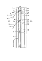
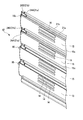
- FIG. 5 It is a disassembled perspective view which shows the shutter apparatus by embodiment of this invention. It is a front view of the shutter apparatus shown in FIG. It is a principal part longitudinal cross-sectional view of the state which closed the movable feather
- FIG. 14 is a horizontal sectional view taken along line AA of FIG.
- FIG. 13 shows the guide rail portion when the slat is in a closed state.
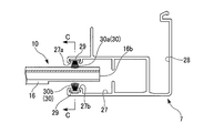
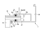
- FIG. 15 is a horizontal sectional view taken along line BB of FIG. 14 showing the guide rail portion when the slat is in an open state. It is a figure of the mohair provided in the room inner side of a receiving part, and the inner surface of the outdoor side. It is a figure of the mohair provided in the indoor inner surface by the modification.
- FIG. 11 is a longitudinal sectional view taken along line CC of the guide rail portion of FIG. 10 showing slats and mohair in a closed state.
- FIG. 12 is a longitudinal sectional view taken along line DD of the guide rail portion of FIG. 11 showing slats and mohair in an open state.
- a frame 3 is formed in an opening 2 of a building.
- the frame 3 has an upper frame 3a, a lower frame 3b, and a pair of left and right vertical frames 3c, and is rectangular. It is formed in a frame shape.
- a shutter unit 6 is installed between the upper top plate 4 of the frame 3 and the upper frame 3a.
- a pair of guide rail portions 7 are attached to the lower portion of the shutter unit 6 and the pair of vertical frames 3 c so that the vertical direction is the longitudinal direction of the guide rail portion 7.
- a shaft 8 and a drive motor 9 are installed inside the shutter unit 6, and a shutter curtain 12 in which a plurality of long slats 10 are connected in the vertical direction is wound around the shaft 8.
- the shutter curtain 12 is rolled up by forward / reverse rotation of the drive motor 9, the opening state of the opening 2 can be obtained, and when the shutter curtain 12 is drawn out and lowered to the lower end, the opening 2 can be closed.
- the vertical movement of the shutter curtain 12 is guided by a pair of guide rail portions 7 that sandwich the shutter curtain 12.
- each slat 10 includes a fixed wing 15 having an opening 14 and a movable wing 16 that is rotatable with respect to the fixed wing 15.
- the lower end portion of the fixed wing 15 of the upper slat 10 and the upper end portion of the movable wing 16 of the lower slat 10 are connected to each other so as to be rotatable.
- the upper two movable wings 16 are in a closed state in contact with the fixed wing 15, and the lower two movable wings 16 are in an opened state in which the fixed wing 15 is opened. Show.
- Each movable wing 16 can be stopped and held during the closed state, the open state, or the opening / closing operation.
- the fixed wing 15 and the movable wing 16 in each slat 10 have a substantially long plate shape that is long in the lateral width direction, and are formed to be curved in an arc shape.
- the fixed wing 15 has an opening 14 formed in an oval shape, and one or a plurality of, for example, three openings 14 are formed separately from each other in the vertical direction.
- a net may be attached to each opening 14.
- the three openings 14 are formed so as to be biased toward the upper side of the fixed wing 15 in the vertical direction.
- An array may be formed.
- the plurality of openings 14 of the fixed wing 15 By arranging the plurality of openings 14 of the fixed wing 15 so as to be biased upward, it is difficult to visually recognize the inside of the opening 14 from the outside when the movable wing 16 is turned to the open state. Moreover, since external light, such as sunlight, reflects on the outer surface of the lower movable wing 16 and the inner surface of the upper movable wing 16 and enters from the opening 14, soft light can be collected. As for wind sampling, the wind can flow into the room through the plurality of openings 14 from the gap between the movable wing 16 and the fixed wing 15 in the open state, and the wind can flow out from the room.
- external light such as sunlight
- three openings 14 having a vertical width of 5 mm are formed above the fixed wing 15 at intervals of 5 mm at a position approximately 10 cm from the lower end of the fixed wing 15.
- the vertical width of the opening 14 5 mm or less even a child's finger cannot pass through. Since the lowermost opening 14 is located above the lower end of the opened movable wing 16, safety, light shielding, and privacy can be secured, and the amount of light collected, the softness of the wind, the amount, etc. can be adjusted.
- a plurality of sets of three openings 14 may be formed at predetermined intervals along the lateral width direction (longitudinal direction) of the fixed wing 15.
- the movable wing 16 is formed in a central region in FIG. 5 and has a main body portion 16a that is substantially the same in length in the vertical width direction as the fixed wing 15 and can open and close the opening 14 of the fixed wing 15; Both end portions are formed by notching, and therefore, the support portion 16b has a longitudinal length smaller than the longitudinal length of the main body portion 16a. Both end portions of the fixed wing 15 and both support portions 16b having a small width of the movable wing 16 are inserted into both the guide rail portions 7 and guided in the vertical movement by the guide rail portions 7.
- connection structure of the plurality of slats 10 will be described with reference to FIGS. 3, 4, 8A, and 8B.
- the connection structure of the plurality of slats 10 has the same configuration at the left and right ends, and in the present embodiment, only one end is shown and described in FIGS. 8A and 8B.
- a first hook portion (holding member, first holding portion) 15a is formed at the upper end portion of the fixed wing 15 so that the hook portion faces the outdoor side, and further below the first hook portion 15a.
- a stopper 15b for stopping the opening operation of the movable wing 16 is formed.
- a second hook portion (holding member, second holding portion) 15c is also formed at the lower end portion of the fixed wing 15, and further, the lower movable wing 16 is pressed to open the second hook portion 15c.
- a pressing portion 18 is formed.
- the movable wing 16 extends from the outer side to the indoor side with the locking portion 20 having a substantially arc-shaped cross section inserted into the first hook portion 15a of the fixed wing 15 at the upper end portion so as to be rotatable.
- a first engagement portion (engagement member) 21a having a substantially L-shaped cross section. Furthermore, it is branched from the first engaging portion 21a and extends upward, and is inserted into a second hook portion 15c formed at the lower end portion of the fixed wing 15 of the slat 10 located on the upper side so as to be rotatable.
- An engaging portion (engaging member) 21b is formed.
- Each of the upper and lower slats 10 is configured such that the second hook portion 15c of the fixed wing 15 of the upper slat 10 and the second engagement portion 21b of the movable wing 16 of the lower slat 10 are rotatably fitted. It is connected. Between the locking part 20 and the first engaging part 21a, the pressing part 18 of the fixed wing 15 of the upper slat 10 receives a pressure to move the movable wing 16 of the lower slat 10 to the first hook part 15a. And a receiving surface 16c that is pivoted about the second hook portion 15c to be opened.
- the shutter curtain 12 is slightly moved downward from the closed position where the main body portion 16a of the movable wing 16 is in contact with the fixed wing 15, and the upper slat 10 is moved.
- the movable wing 16 is rotated and separated from the fixed wing 15 as shown in FIG. 4. Open operation.
- the opening operation of the movable wing 16 is stopped when the first engagement portion 21a comes into contact with the stopper 15b of the fixed wing 15, and the movable wing 16 is opened at a predetermined angle, for example, an acute angle with respect to the fixed wing 15. Retained.
- a predetermined angle for example, an acute angle with respect to the fixed wing 15. Retained.
- the opening 14 of the fixed wing 15 is difficult to visually recognize from the outside. External light such as sunlight is reflected by the outer surface of the lower movable wing 16 and the inner surface of the upper movable wing 16 and is incident from the opening 14 and collected.
- the first hook portion 15a formed at the upper end portion of the fixed wing 15 has a shorter length in the width direction than the fixed wing 15. .
- the first engagement portion 21a at the end of the movable wing 16 is caulked through a cutout portion 23 formed by cutting out the first engagement portion 21a of the movable wing 16, and the first caulking portion (movement restricting portion). 24A is formed. Therefore, the sliding range of the movable wing 16 in the width direction with respect to the fixed wing 15 of each slat 10 is restricted by the first caulking portions 24A at both ends. Accordingly, it is possible to prevent the movable wing 16 from being laterally displaced or detached from the fixed wing 15 of the slat 10 in the width direction.
- the second hook portion 15 c at the lower end formed on the fixed wing 15 of the upper slat 10 has a shorter length in the width direction than the fixed wing 15.
- the second engagement portion 21b at the end of the movable wing 16 is caulked through a notch 25 formed by notching the second engagement portion 21b of the movable wing 16, and the second caulking portion (movement restricting portion). 24B is formed. Therefore, the sliding range in the width direction of the lower movable wing 16 with respect to the upper fixed wing 15 is regulated by the second caulking portions 24B at both ends. Therefore, it is possible to prevent the lower movable wing 16 from laterally shifting or coming off in the width direction from the upper fixed wing 15.
- wing 16 are the same length as the length of the support part 16b formed in both sides.
- the first hook portion 15a of the fixed wing 15 has a length to the notches 23 on both sides of the first engaging portion 21a, and the second hook portion 15c has a length to the notches 25 on both sides of the second engaging portion 21b.
- the guide rail part 7 that guides the vertical movement of the shutter curtain 12 will be described with reference to FIGS.
- the guide rail part 7 is also arrange
- FIG. 9 the pair of guide rail portions 7 fixed to the pair of left and right vertical frames 3 c of the frame 3 each have a cross section that guides each slat 10 of the shutter curtain 12 so as to be movable up and down. It has the substantially U-shaped receiving part 27 and the attachment part 28 connected with the vertical frame 3c.
- the end of the fixed wing 15 of each slat 10 and the support portion 16b of the movable wing 16 are inserted into the inside.
- the horizontal opening width of both ends of the slat 10 and the opening width of the receiving portion 27 are set to be substantially the same.
- Mohair 30 is implanted as a fibrous body on the base 29 on the inner surfaces 27a and 27b facing the receiving portion 27, respectively.
- the mohair 30 fills the gap between the opening of the receiving portion 27 of the guide rail portion 7 and the shutter curtain 12 and has a function as a silencer to guide the vertical movement of the shutter curtain 12.
- the mohairs 30 on the inner surfaces 27a and 27b are composed of a plurality of rows of fibers.
- the mohairs 30a and 30b respectively provided on the indoor and outdoor inner surfaces 27a and 27b are fibers 31 having relatively small thickness and small hardness and fibers 32 having relatively large thickness and large hardness. And two types of fibers.
- the mohairs 30a, 30b on the inner surfaces 27a, 27b extend in three rows in the vertical direction of the guide rail portion 7, the mohairs 30a, 30b on the inner and outer inner surfaces 27a, 27b are as shown in FIG. 12A. It is composed of two rows of soft fibers 31 and one row of fibers 32 having a large thickness and hardness.
- the mohair 30a on the indoor inner surface 27a is soft with, for example, all three rows of fibers 31 as shown in FIG. 12B, and the mohair 31b on the outdoor inner surface 27b is soft with two rows of fibers 31 as shown in FIG. 12A. You may be comprised with the hard line 32 of fibers.
- the slat 10 in the closed state fits between the mohairs 30 a and 30 b provided on the inner surfaces 27 a and 27 b of the receiving portion 27 of the guide rail portion 7 and can move up and down.
- the narrow support portion 16 b of the movable wing 16 abuts against the mohairs 30 a and 30 b of the inner surfaces 27 a and 27 b in the receiving portion 27.
- the end of the support portion 16b that is relatively separated from the first and second engaging portions 21a and 21b on the outdoor side comes into contact with the mohair 30b in which rows of fibers 32 having high hardness are mixed, so that its own weight Resists descent due to and prevents descent.
- the slat 10 is lifted upward from the outside by manual operation or the like, it is resisted by the mohairs 30a and 30b.
- each slat 10 does not contact or slightly contacts the mohairs 30a and 30b, so that the shutter curtain 12 can be moved up and down by holding the shutter curtain 12 open and close. it can.
- the drive motor 9 is driven to rotate in one direction by a switch (not shown) and the shutter curtain 12 is unwound from the state wound up on the shaft 8. Further, as shown in FIGS. 2 and 3, the movable wings 16 of the respective slats 10 of the shutter curtain 12 are lowered by being guided by the guide rail portions 7 on both sides in the closed state where the movable wings 16 are in contact with the fixed wings 15.
- the base plate 13 at the lower end of the shutter curtain 12 abuts against the lower frame 3b of the frame 3, and a change in load is detected by a detection means such as an encoder attached to the drive motor 9, or the base plate 13 or By detecting with a sensor or the like provided on the lower frame 3b or the like, the descent stops.
- a detection means such as an encoder attached to the drive motor 9, or the base plate 13 or By detecting with a sensor or the like provided on the lower frame 3b or the like, the descent stops.
- the opening 2 is closed by a shutter curtain 12.
- the shutter curtain 12 is slightly moved downward by the drive motor 9.
- the receiving surface 16 c of the movable wing 16 of the lower slat 10 is pushed by the pressing portion 18 at the lower end of the fixed wing 15 of each slat 10. Therefore, the movable wing 16 is movable by rotating around the first engagement portion 21a fitted to the first hook portion 15a and the second engagement portion 21b fitted to the second hook portion 15c.
- the wing 16 opens in the outdoor direction by a predetermined angle. Then, the first engaging portion 21a comes into contact with the stopper 15b of the fixed wing 15 and stops in the open state.
- the driving motor 9 is rotated in the reverse direction and the shutter curtain 12 is moved slightly upward so that the pressing portion 18 is separated from the receiving surface 16c of the movable wing 16 and the movable wing 16 is moved away.
- the opening 14 is closed by contacting the fixed wing 15 with its own weight.
- the drive motor 9 is further rotated in the reverse direction to wind up the shutter curtain 12 around the shaft 8. Further, when each slat 10 moves up and down in the closed state, as shown in FIGS. 10 and 13, the fixed wing 15 and the movable wing 16 of each slat 10 have both guide rail portions at both ends thereof.
- the slat 10 when the movable wing 16 of the slat 10 is in an open state with respect to the fixed wing 15, the slat 10 has the same width as that between the mohairs 30 a and 30 b of the inner surfaces 27 a and 27 b of the receiving portions 27 of the guide rail portion 7. And abut against each other. Moreover, as shown in FIGS. 11 and 14, the support portions 16 b at both ends of the movable wing 16 abut against the mohair 30 b including the hard fibers 32 on the inner surface 27 b in an open state, thereby reducing the load in the descending direction due to its own weight. The movable wing 16 is kept open by the hardness of the mohairs 30a and 30b. Further, when the pressing portion 18 of the fixed wing 15 is separated from the receiving surface 16c of the movable wing 16, it is allowed that the support portion 16b overcomes the resistance of the mohairs 30b and 30a and closes with its own weight.
- the first caulking portion 24A and the second caulking portion 24B perform each movable wing. It can control that 16 shifts laterally to fixed wing 15.
- the movable wing 16 in each slat 10 of the shutter curtain 12, the movable wing 16 is regulated by the first caulking portion 24A so as not to be laterally displaced with respect to the fixed wing 15. It can be regulated that the movable wing 16 is displaced laterally from the fixed wing 15 or detached after assembly. Further, since each movable wing 16 is regulated by the second caulking portion 24B so as not to be laterally displaced with respect to the upper fixed wing 15, the slat 10 including the movable wing 16 after assembly is laterally displaced from the fixed wing 15 of the upper slat 10. Can be controlled.
- first caulking portion 24A provided at both ends of the first engaging portion 21a of the movable wing 16 and the second caulking portion 24B provided at both ends of the second engaging portion 21b are respectively relative to each other by the notches 23 and 25. Since it is separated from the portion that contributes to the rotation, even if both ends of the first engagement portion 21a and the second engagement portion 21b are caulked, the rotation of the movable wing 16 relative to the fixed wing 15 is not affected. Therefore, the shutter device 1 according to the present embodiment can be easily manufactured by an automatic machine without a separate component attaching step, and processing costs can be reduced. Moreover, since the first and second caulking portions 24A and 24B are provided on the same surface side of the movable wing 16, the caulking operation is further facilitated.
- mohairs 30a and 30b are provided on the inner surfaces 27a and 27b of the receiving portions 27 of the guide rail portion 7 for inserting the both ends of each slat 10 to guide the vertical movement. Since at least the outdoor mohair 30b is mixed with the fiber 31 having relatively high hardness 32, the resistance of the mohair 30b that comes into contact with the support portion 16b when the movable wing 16 is opened can be increased. 16b can be stably locked and maintained in an open state, and the aged deterioration of the mohairs 30a and 30b can be suppressed. Furthermore, when the movable wing 16 is in the closed state, it can be moved up and down stably by moving the slats 10 with the mohairs 30a and 30b.
- each slat 10 since the plurality of openings 14 are arranged so as to be biased to the upper part of the fixed wing 15, when the movable wing 16 is in an open state, it is possible to prevent others from seeing the room from the outside through the opening 14. . Therefore, safety, light shielding, and privacy can be ensured, and furthermore, the balance between the amount of light passing through the opening 14 and the air volume can be adjusted.
- the shutter device 1 according to the present invention is not limited to the above-described embodiment, and can be appropriately changed or replaced without departing from the gist of the present invention.
- modifications of the present invention will be described, but the same or similar components or members described in the above-described embodiment will be described using the same reference numerals.
- the cutout portion 23 is formed closer to the center in the longitudinal direction of the first engagement portion 21a than the first caulking portions 24A formed at both ends of the first engagement portion 21a in the movable wing 16.
- the notch 23 may not be provided.
- the first caulking portion 24A may be formed so that the first caulking portion 24A is not affected.
- the second engaging portion 21b of the movable wing 16 is moved away from both ends of the second hook portion 15c of the fixed wing 15 in the longitudinal direction (relative rotation with the second hook portion 15c). If the second caulking portion 24B is formed (so as not to be affected), the notch portion 25 may not be provided in the second engaging portion 21b. Thus, the first and second caulking portions 24A and 24B can be formed without affecting the relative rotation between the fixed wing 15 and the movable wing 16.
- the first engaging portion 21a at the end of the movable wing 16 is caulked through the notch portion 23 formed by notching the first engaging portion 21a of the movable wing 16.
- a crimped portion 24A is formed. However, the end portion of the first hook portion 15a may be caulked through a notch portion formed by notching the first hook portion 15a to form the first caulking portion.
- the first caulking portion 24A and the second caulking portion 24B are formed at both end portions of the first engaging portion 21a and the second engaging portion 21b of the movable wing 16, respectively.
- the first hook portion 15a and the second hook portion 15c are not laterally displaced.
- both ends of the first engaging portion 21a and the second engaging portion 21b of the movable wing 16 are formed short, and the first hook portion 15a and the second hook portion 15c of the fixed wing 15 are formed. Both ends may be formed longer than the first engaging portion 21a and the second engaging portion 21b, and a notch portion may be formed outward in the longitudinal direction at both ends of the first engaging portion 21a and the second engaging portion 21b. Good.
- the first staking part and the second staking part are respectively formed on the outer sides in the longitudinal direction at both ends of the first engaging part 21a and the second engaging part 21b without forming the notch part. You may make it prevent lateral shift
- the second engaging portion 21b at the end of the movable wing 16 is caulked through the notch 25 formed by notching the second engaging portion 21b of the movable wing 16.
- a double caulking portion 24B is formed.
- the end portion of the second hook portion 15c may be caulked through a notch portion formed by notching the second hook portion 15c to form a second caulking portion.
- first caulking portion 24A and second caulking portion 24B are provided, but the movement restricting portion is provided only at one place to restrict the movement of the slats. It may be a thing.
- Mohairs 30a and 30b in which fibers 32 having a relatively large thickness and fibers 31 having a small thickness are mixed are installed on both inner surfaces 27a and 27b of the receiving portion 27 of the guide rail portion 7 which are opposed to each other.
- the mohair 30a provided on the inner inner surface 27a may be configured by arranging only the fibers 31 having low hardness along the longitudinal direction. Even in this case, the support portion 16b of the movable wing 16 abuts on the mohairs 30a and 30b and is maintained in the open state.
- the fibers 32 having a large thickness are not limited to be arranged side by side in a row of fibers 31 having a small thickness, and may be mixed in any row of fibers 31 or a plurality of fibers 31 may be mixed. It may be mixed randomly in the column.
- the fibers constituting the mohair 30b and the like are not limited to two types, and three or more types of fibers having different hardnesses may be used.
- the resistor that maintains the support 16b of the movable wing 16 in the open state is not limited to the mohair 30, and other resistors such as an elastic body such as a sponge may be provided.
- the number of openings 14 provided in the fixed wing 15 is not limited to three in the vertical width direction, but may be two or four or more, and a plurality of appropriate openings 14 can be formed.
- the opening 14 is not limited to the one extending in the width direction of the fixed wing 15.
- a plurality of openings 14 extending in the vertical width direction of the fixed wing 15 may be arranged in the horizontal width direction to form a set of openings.
- the openings 14 may be formed obliquely and arranged in parallel.
- the opening 14 of the fixed wing 15 is positioned eccentrically upward with respect to the horizontal extension line of the lower end of the movable wing 16 in the open state, but may be eccentric downward.
- the first hook portion 15a of the fixed wing in the present invention constitutes a first holding portion
- the second hook portion 15c constitutes a second holding portion
Landscapes
- Engineering & Computer Science (AREA)
- Structural Engineering (AREA)
- Architecture (AREA)
- Civil Engineering (AREA)
- Operating, Guiding And Securing Of Roll- Type Closing Members (AREA)
Abstract
シャッター装置は、保持部材を有しかつ開口を有する固定羽と、保持部材と回動可能に嵌合された係合部材を有する可動羽と、を有するスラットと、スラットが連結され、連結されたスラットの相対移動により固定羽に対して可動羽が回動作動されるシャッターカーテンと、を備え、係合部材又は保持部材の少なくとも一方には、可動羽と固定羽とがスライド移動することを規制する移動規制部材が設けられている。
Description
本発明は、建物の開口部に用いられていてスラットによって採光、通風等の可能なシャッター装置に関する。
本願は、2013年11月20日に出願された日本国特許出願第2013-240296号、日本国特許出願第2013-240297号、及び日本国特許出願第2013-240298号に基づき優先権を主張し、その内容をここに援用する。
本願は、2013年11月20日に出願された日本国特許出願第2013-240296号、日本国特許出願第2013-240297号、及び日本国特許出願第2013-240298号に基づき優先権を主張し、その内容をここに援用する。
従来、スラットをブラインドとして用いた採光、通風等の可能なシャッターカーテンとして、例えば特許文献1に記載されたシャッター装置が提案されている。
上述したシャッター装置は固定羽と可動羽が重ねて設けられたスラットが上下方向に複数連結されていて、シャッターカーテンが建物の開口部を閉鎖させた閉鎖状態で可動羽を開閉操作させることができる。
上述したシャッター装置は固定羽と可動羽が重ねて設けられたスラットが上下方向に複数連結されていて、シャッターカーテンが建物の開口部を閉鎖させた閉鎖状態で可動羽を開閉操作させることができる。
上述したシャッター装置では、上下方向に配列された複数のスラットにおいて上側のスラットに設けた固定羽で下側のスラットに設けた可動羽を押すことで、可動羽を回動させて開作動させ、固定羽の開口を通して採光や通風等ができる。しかも、開状態にある可動羽によって外部から室内を視認しにくい状態にすることができる。
上述したシャッター装置では、上側のスラットと下側のスラットとの連結部及び各スラットにおける固定羽に対する可動羽の連結部には、両端部に固定部材が設置され、上側のスラットに対して下側のスラットが横ずれしたり、各スラットの固定羽に対して可動羽が横ずれしたりすることを防いでいる。
特許文献2に記載されたシャッター装置では、スラット端部を収納したガイドレール部に設けたリンク機構でスラットの開閉作動等を安定させて行っている。そして、リンク機構を動かすことでスラットの開き角度を調整するので各スラットの細かな開閉動作を制御することができる。
また、特許文献1に記載されたシャッター装置では、各スラットの固定羽には固定羽の縦幅方向の中央に略長方形状の1つの開口が形成され、この開口は固定羽の横幅方向に所定間隔を開けて複数配列されている。また、各開口には防虫ネットを貼ることで虫等が入らないようにしている場合がある。
特許文献1に記載されたシャッター装置では、上下のスラットの横ずれ及び固定羽に対する可動羽の横ずれを防ぐために、別部品の固定部材を固定羽及び可動羽の両端部に取り付ける必要がある。そのため、組み立てが煩雑で手間がかかり、更にコスト高になる欠点があった。
また、特許文献2に記載されたシャッター装置では、リンク機構をスラットごとに連動させる構成であるために、スラットごとにリンクや駆動機構等の多数の専用部品が必要になり、部品点数が非常に多くなるという欠点があった。
更に、特許文献1に記載されたシャッター装置では、固定羽の縦幅方向の中央に略長方形状の開口が形成されているために、可動羽の開状態で太陽光の取り込み、採風の流通等が容易である。しかし一方で、開状態にある可動羽と固定羽との隙間または固定羽の開口を通して外部から室内を目視し易く、プライバシーの保護を充分図れない欠点があった。また、固定羽の開口は比較的大きな面積であるために指等が開口から容易に入り易く、防犯が不十分であるという欠点があった。
本発明は、上記課題に鑑みてなされたものであって、スラット同士の横ずれ及び固定羽に対する可動羽の横ずれを、別部品を設けることなく規制できるシャッター装置を提供する。
また、本発明は、スラットの開閉作動を少ない部品で簡単な機構を用いて制御できるシャッター装置を提供する。
更に、本発明は、採光と通風を調整しつつ、安全性とプライバシーの保護を確保できるシャッター装置を提供する。
本発明の第1態様は、シャッター装置であって、保持部材を有しかつ開口を有する固定羽と、保持部材と回動可能に嵌合された係合部材を有する可動羽と、を有するスラットと、スラットが連結され、連結されたスラットの相対移動により固定羽に対して可動羽が回動作動されるシャッターカーテンと、を備え、係合部材又は保持部材の少なくとも一方には、可動羽と固定羽とがスライド移動することを規制する移動規制部材が設けられている。
上記第1態様によれば、スラット同士の横ずれ及び固定羽に対する可動羽の横ずれを、別部品を設けることなく規制できるシャッター装置を提供できる。
ここで、可動羽と固定羽の相対移動とは、上下に連結される可動羽と固定羽において、係合部材と移動規制部との間に形成される空間内を各スラットが移動することを意味する。
本発明の第2態様は、上記第1態様のシャッター装置において、保持部材は、固定羽の上端に設けられる第一保持部と、固定羽の下端に設けられる第二保持部と、を有し、係合部材は、第一保持部と回動可能に嵌合された第一係合部と、第一保持部に嵌合する可動羽とは異なる第二可動羽に設けられる第二係合部と、を有する。
上記第2態様によれば、スラット同士の横ずれ及び固定羽に対する可動羽の横ずれを、別部品を設けることなく規制できるシャッター装置を提供できる。
本発明の第3態様は、上記第1態様のシャッター装置において、可動羽は、連結されたスラットの相対移動により固定羽の開口を開閉する。
上記第3態様によれば、スラットの開閉作動を少ない部品で簡単な機構を用いて制御できるシャッター装置を提供できる。
上記第1態様によれば、スラット同士の横ずれ及び固定羽に対する可動羽の横ずれを、別部品を設けることなく規制できるシャッター装置を提供できる。
ここで、可動羽と固定羽の相対移動とは、上下に連結される可動羽と固定羽において、係合部材と移動規制部との間に形成される空間内を各スラットが移動することを意味する。
本発明の第2態様は、上記第1態様のシャッター装置において、保持部材は、固定羽の上端に設けられる第一保持部と、固定羽の下端に設けられる第二保持部と、を有し、係合部材は、第一保持部と回動可能に嵌合された第一係合部と、第一保持部に嵌合する可動羽とは異なる第二可動羽に設けられる第二係合部と、を有する。
上記第2態様によれば、スラット同士の横ずれ及び固定羽に対する可動羽の横ずれを、別部品を設けることなく規制できるシャッター装置を提供できる。
本発明の第3態様は、上記第1態様のシャッター装置において、可動羽は、連結されたスラットの相対移動により固定羽の開口を開閉する。
上記第3態様によれば、スラットの開閉作動を少ない部品で簡単な機構を用いて制御できるシャッター装置を提供できる。
本発明の第4態様は、上記第2態様のシャッター装置において、第一係合部は長手方向において第一保持部より長く、第一係合部の少なくとも一方の端部に第一移動規制部が形成されている、または、第一保持部は長手方向において第一係合部より長く、第一保持部の少なくとも一方の端部に第一移動規制部が形成されている。
上記第4態様によれば、シャッター装置の各スラットにおいて、互いに嵌合する可動羽の第一係合部と固定羽の第一保持部とのいずれか一方の両端が対応するいずれか他方の両端より長く形成されている。さらに、他方の端部より長手方向外方に位置する一方の両端部に第一移動規制部をそれぞれ形成したため、固定羽によって可動羽を回動可能に支持すると共に、固定羽と可動羽が相互に横ずれしたりすることを第一移動規制部で阻止できる。
本発明の第5態様は、上記第2態様のシャッター装置において、第二係合部は長手方向において第二保持部より長く、第二係合部の少なくとも一方の端部に第二移動規制部が形成されている、または、第二保持部は長手方向において第二係合部より長く、第二保持部の少なくとも一方の端部に第二移動規制部が形成されている。
上記第4態様によれば、シャッター装置の各スラットにおいて、互いに嵌合する可動羽の第一係合部と固定羽の第一保持部とのいずれか一方の両端が対応するいずれか他方の両端より長く形成されている。さらに、他方の端部より長手方向外方に位置する一方の両端部に第一移動規制部をそれぞれ形成したため、固定羽によって可動羽を回動可能に支持すると共に、固定羽と可動羽が相互に横ずれしたりすることを第一移動規制部で阻止できる。
本発明の第5態様は、上記第2態様のシャッター装置において、第二係合部は長手方向において第二保持部より長く、第二係合部の少なくとも一方の端部に第二移動規制部が形成されている、または、第二保持部は長手方向において第二係合部より長く、第二保持部の少なくとも一方の端部に第二移動規制部が形成されている。
上記第5態様によれば、シャッター装置の各スラットにおいて、互いに嵌合する固定羽の第二保持部と可動羽の第二係合部のいずれか一方の両端が対応するいずれか他方の両端より長く形成されている。さらに、他方の端部より長手方向の外方に位置する一方の両端部に第二移動規制部をそれぞれ形成したため、上側の固定羽によって下側の可動羽を回動可能に支持すると共に、上側の固定羽と下側の可動羽が相互に横ずれしたりすることを第二移動規制部で阻止できる。
本発明の第6態様は、上記第4態様のシャッター装置において、第一移動規制部よりも第一係合部の長手方向中央寄りに形成された切欠部をさらに備え、第一係合部は長手方向において第一保持部より長く、第一保持部の少なくとも一方の端部が第一移動規制部よりも第一係合部の長手方向中央寄りに位置するように形成されている、または、第一保持部は長手方向において第一係合部より長く、第一係合部の少なくとも一方の端部が第一移動規制部よりも第一係合部の長手方向中央寄りに位置するように形成されている。
上記第6態様によれば、切欠部によって第一移動規制部を相対的に回動可能な第一係合部または第一保持部の内側部分と分離できるため、回動部分に影響を与えることなく第一係合部または第一保持部の両端部をかしめて第一移動規制部を形成することができる。そのため、かしめ加工の自動化が容易である。
上記第6態様によれば、切欠部によって第一移動規制部を相対的に回動可能な第一係合部または第一保持部の内側部分と分離できるため、回動部分に影響を与えることなく第一係合部または第一保持部の両端部をかしめて第一移動規制部を形成することができる。そのため、かしめ加工の自動化が容易である。
本発明の第7態様は、上記第5態様のシャッター装置において、第二移動規制部よりも第一係合部の長手方向中央寄りに形成された切欠部をさらに備え、第二係合部は長手方向において第二保持部より長く、第二保持部の少なくとも一方の端部が第二移動規制部よりも第二係合部の長手方向中央寄りに位置するように形成されている、または、第二保持部は長手方向において第二係合部より長く、第二係合部の少なくとも一方の端部が第二移動規制部よりも第二係合部の長手方向中央寄りに位置するように形成されている。
上記第7態様によれば、切欠部によって第二移動規制部を相対的に回動可能な第二係合部または第二保持部の内側部分と分離できるため、回動部分に影響を与えることなく第二係合部または第二保持部の両端部をかしめて第二移動規制部を形成することができる。そのため、かしめ加工の自動化が容易である。
上記第7態様によれば、切欠部によって第二移動規制部を相対的に回動可能な第二係合部または第二保持部の内側部分と分離できるため、回動部分に影響を与えることなく第二係合部または第二保持部の両端部をかしめて第二移動規制部を形成することができる。そのため、かしめ加工の自動化が容易である。
本発明の第8態様は、シャッター装置であって、開口を設けた固定羽と開口を開閉可能な可動羽とを有するスラットと、スラットが連結され、該連結されたスラットの相対移動により固定羽に対して可動羽が開閉作動されるシャッターカーテンと、スラットの端部の上下動をガイドする受け入れ部を有するガイドレール部と、ガイドレール部の受け入れ部内に設けられ、可動羽の端部に設けた支持部に当接可能な抵抗体と、を備え、抵抗体は第1抵抗体と、第1抵抗体よりも大きい接触抵抗を有する第2抵抗体とを含む。
上記第8態様によれば、スラットの可動羽が開作動した状態で、可動羽の端部に形成した支持部が、ガイドレール部の受け入れ部内に対向して設けた抵抗体に当接して開状態にある可動羽を支持できる。特に、一部の抵抗体の接触抵抗が大きいので、開状態にある可動羽の支持部の開閉作動に抵抗して、安定して可動羽を保持できる。また、抵抗体として接触抵抗の大きい一部の抵抗体と接触抵抗の小さい他の抵抗体とを混在させたことで、簡単な構成で確実に可動羽を開状態に保持できる。さらに、閉状態では、支持部が抵抗体に当接しないか当接が少ないために、スラットが容易に上下動できる。
上記第8態様によれば、スラットの可動羽が開作動した状態で、可動羽の端部に形成した支持部が、ガイドレール部の受け入れ部内に対向して設けた抵抗体に当接して開状態にある可動羽を支持できる。特に、一部の抵抗体の接触抵抗が大きいので、開状態にある可動羽の支持部の開閉作動に抵抗して、安定して可動羽を保持できる。また、抵抗体として接触抵抗の大きい一部の抵抗体と接触抵抗の小さい他の抵抗体とを混在させたことで、簡単な構成で確実に可動羽を開状態に保持できる。さらに、閉状態では、支持部が抵抗体に当接しないか当接が少ないために、スラットが容易に上下動できる。
本発明の第9態様は、上記第8態様のシャッター装置において、抵抗体は複数の繊維を有する繊維体であることが好ましい。
上記第9態様によれば、抵抗体が複数の繊維からなることで、可動羽の支持部が開閉作動する際に、繊維が個別に変位して作動時の抵抗を比較的小さくできる。しかも、開状態にある可動羽と繊維体との当接による抵抗が、接触抵抗の大きい一部の抵抗体によって大きくなる。
上記第9態様によれば、抵抗体が複数の繊維からなることで、可動羽の支持部が開閉作動する際に、繊維が個別に変位して作動時の抵抗を比較的小さくできる。しかも、開状態にある可動羽と繊維体との当接による抵抗が、接触抵抗の大きい一部の抵抗体によって大きくなる。
本発明の第10態様は、上記第9態様のシャッター装置において、ガイドレール部の受け入れ部の対向する内面に、繊維体がガイドレール部の長手方向に沿ってそれぞれ設けられ、接触抵抗の大きい一部の繊維はガイドレール部の長手方向に沿って配列されていてもよい。
上記第10態様によれば、ガイドレール部の受け入れ部の対向する内面に繊維体がガイドレール部の長手方向に沿ってそれぞれ設けられている。そのため、上下方向に複数連結されたスラットの各可動羽が開状態において、支持部が長手方向に沿って配列された繊維体に当接しする。しかも、接触抵抗の大きい一部の繊維も長手方向に配列しているから、上下方向の各スラットの可動羽を大きな接触抵抗で確実に保持できる。
なお、接触抵抗の大きい繊維は、比較的太さの大きい繊維である。
上記第10態様によれば、ガイドレール部の受け入れ部の対向する内面に繊維体がガイドレール部の長手方向に沿ってそれぞれ設けられている。そのため、上下方向に複数連結されたスラットの各可動羽が開状態において、支持部が長手方向に沿って配列された繊維体に当接しする。しかも、接触抵抗の大きい一部の繊維も長手方向に配列しているから、上下方向の各スラットの可動羽を大きな接触抵抗で確実に保持できる。
なお、接触抵抗の大きい繊維は、比較的太さの大きい繊維である。
本発明の第11態様は、シャッター装置であって、複数の開口を設けた固定羽と複数の開口を開閉可能な可動羽とを有するスラットと、スラットが連結され、連結されたスラットの相対移動により固定羽に対して可動羽が開閉作動されるシャッターカーテンと、を備え、複数の開口は、互いに分離して配列され、複数の開口を開閉可能な可動羽と固定羽との連結部寄りに偏心して配列されている。
上記第11態様によれば、スラットの固定羽に設けた開口は互いに分離して複数配列されると共に、可動羽と固定羽との連結部側に偏心して配列させている。そのため、開状態にある可動羽との間で太陽光等の光が可動羽等で反射して複数の開口を通して入射するため、柔らかな光を採光できる。更に、風も可動羽と固定羽との間から複数の開口を通して流通するため、柔らかな風を流通させることができる。しかも、複数の開口は開状態にある可動羽と固定羽との連結部側に偏心して配列されている。そのため、外部から開口を通して内部を目視することを可動羽で規制することができる。また、開口を複数に分割したため、個々の開口の幅が小さく、指などが入りにくいので防犯性が高い。
上記第11態様によれば、スラットの固定羽に設けた開口は互いに分離して複数配列されると共に、可動羽と固定羽との連結部側に偏心して配列させている。そのため、開状態にある可動羽との間で太陽光等の光が可動羽等で反射して複数の開口を通して入射するため、柔らかな光を採光できる。更に、風も可動羽と固定羽との間から複数の開口を通して流通するため、柔らかな風を流通させることができる。しかも、複数の開口は開状態にある可動羽と固定羽との連結部側に偏心して配列されている。そのため、外部から開口を通して内部を目視することを可動羽で規制することができる。また、開口を複数に分割したため、個々の開口の幅が小さく、指などが入りにくいので防犯性が高い。
本発明の第12態様は、上記第11態様のシャッター装置において、複数の開口は、固定羽に対して開状態にある可動羽の下端部の水平方向の延長線に対して、連結部寄りに位置することが好ましい。
上記第12態様によれば、固定羽の開口を、開状態にある可動羽の下端部より連結部側に形成したから、外部から開口を通して内部を目視されることを防いでプライバシーの保護と安全性を確保できる。
上記第12態様によれば、固定羽の開口を、開状態にある可動羽の下端部より連結部側に形成したから、外部から開口を通して内部を目視されることを防いでプライバシーの保護と安全性を確保できる。
本発明の第13態様は、上記第11または第12態様のシャッター装置において、複数の開口は、固定羽の横幅方向に延び、縦幅方向に沿って配列されて構成され、固定羽の横幅方向に間隔を開けて配列されていてもよい。
上記第13態様によれば、開口を縦幅方向に複数に分割し、固定羽の幅方向に複数組形成している。そのため、固定羽の強度を確保しながら開口をバランス良く多数形成することができて、開口を通した採光と通風を調整できる。
上記第13態様によれば、開口を縦幅方向に複数に分割し、固定羽の幅方向に複数組形成している。そのため、固定羽の強度を確保しながら開口をバランス良く多数形成することができて、開口を通した採光と通風を調整できる。
本発明の第14態様は、上記第11から第13態様のシャッター装置において、可動羽の下端部は、開状態で固定羽に設けた複数の開口よりも下部に配置されていてもよい。
上記第14態様によれば、開状態で可動羽を固定羽に対して鋭角に開いた状態に保持するから、外部から開口を通して内部を目視されることを抑制できてプライバシーの保護に有効である。
上記第14態様によれば、開状態で可動羽を固定羽に対して鋭角に開いた状態に保持するから、外部から開口を通して内部を目視されることを抑制できてプライバシーの保護に有効である。
上記本発明に係る態様によれば、別の固定部品を取り付けることなく、可動羽の第一係合部と固定羽の第一保持部のいずれか一方の両端部を第一かしめ部でかしめることで、スラットの固定羽に対して可動羽の回動を許容して相対的な横ずれを規制できる。
また、可動羽の第二係合部と固定羽の第二保持部のいずれか一方の両端部を第二かしめ部でかしめることで、上スラットの固定羽に対して下スラットの可動羽の回動を許容して相対的な横ずれを規制できる。
また、可動羽の第二係合部と固定羽の第二保持部のいずれか一方の両端部を第二かしめ部でかしめることで、上スラットの固定羽に対して下スラットの可動羽の回動を許容して相対的な横ずれを規制できる。
上記本発明に係る態様によれば、スラットの可動羽が開作動した状態で、スラットの端部に形成した支持部が、ガイドレール部の受け入れ部内に設けた抵抗体に当接して開状態にある可動羽を支持できる。特に、一部の抵抗体の接触抵抗が大きいので開状態にある可動羽の支持部の上下動に抵抗して、可動羽を安定して保持できる。
また、抵抗体として接触抵抗の大きい一部の抵抗体と接触抵抗の小さい他の抵抗体とを混在させたことで、可動羽を開状態に保持できると共に、閉状態では抵抗体に当接しないか当接が少ないために、スラットが容易に上下動できる。
更に、ガイドレール部の受け入れ部内に対向して抵抗体を設置するのみであるため、部品点数が少なくてコストを低廉にできる。
更に、ガイドレール部の受け入れ部内に対向して抵抗体を設置するのみであるため、部品点数が少なくてコストを低廉にできる。
上記本発明に係る態様によれば、スラットの固定羽に設けた開口は互いに分割して複数配列されると共に、可動羽と固定羽との連結部側に偏心して配列させている。そのため、開状態にある可動羽との間で太陽光等の光が可動羽等で反射して複数の開口を通して入射するため、柔らかな光を充分採光できる。更に、風も可動羽と固定羽との間から複数の開口を通して流通するため、風を広範囲に取り込み易い。
更に、複数の開口は開状態にある可動羽と固定羽との連結部側に偏心して配列されている。そのため、外部から開口を通して内部を目視することを可動羽で妨げることができる。また、開口を複数に分割して配設したため、個々の開口の幅が小さく、指などが入りにくいので防犯上の安全性が高い。
以下、本発明の実施形態によるシャッター装置を図1~図14に基づいて説明する。
図1及び図2に示す実施形態によるシャッター装置1では、建物の開口部2にフレーム3が形成され、フレーム3は上枠3aと下枠3bと左右一対の縦枠3cとを有し、四角形枠状に形成されている。フレーム3の上天板4と上枠3aとの間にシャッターユニット6が設置されている。シャッターユニット6の下部及び一対の縦枠3cに、一対のガイドレール部7それぞれが、上下方向がガイドレール部7の長手方向となるように取り付けられている。
図1及び図2に示す実施形態によるシャッター装置1では、建物の開口部2にフレーム3が形成され、フレーム3は上枠3aと下枠3bと左右一対の縦枠3cとを有し、四角形枠状に形成されている。フレーム3の上天板4と上枠3aとの間にシャッターユニット6が設置されている。シャッターユニット6の下部及び一対の縦枠3cに、一対のガイドレール部7それぞれが、上下方向がガイドレール部7の長手方向となるように取り付けられている。
シャッターユニット6の内部にはシャフト8と駆動モータ9とが設置され、シャフト8には、長尺の複数のスラット10が上下方向に連結されたシャッターカーテン12が巻回されている。駆動モータ9の正逆回転により、シャッターカーテン12を巻き上げれば開口部2の開口状態を得られ、シャッターカーテン12を繰り出して下端まで降下させれば開口部2の閉鎖状態を得られる。シャッターカーテン12の上下動は、シャッターカーテン12を挟む一対のガイドレール部7によってガイドされる。
次に、シャッターカーテン12の構造について図3~図6により説明する。シャッターカーテン12において、その上端部と下端部に設けられた巾木13との間に複数のスラット10が互いに回動可能に上下方向に連結されている。各スラット10は、開口14を備えた固定羽15と、固定羽15に対して回動可能な可動羽16とを備える。上側のスラット10の固定羽15の下端部と下側のスラット10の可動羽16の上端部とが回動可能に連結されて上下方向に連なっている。なお、図5、図6において、上側の2枚の可動羽16は固定羽15に当接した閉状態を示し、下側の2枚の可動羽16は固定羽15から開作動した開状態を示している。各可動羽16は、閉状態、開状態、または開閉作動の途中で停止保持可能である。
各スラット10における固定羽15と可動羽16とは横幅方向が長尺である略長板状であり、円弧状に湾曲して形成されている。固定羽15には、開口14が長円形状に形成され、1または複数、例えば3つの開口14が上下方向に互いに分離して形成されている。なお、各開口14にネットを貼り付けてもよい。
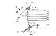
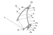
本実施形態に示す例では、図6~図7Bに示すように、3つの開口14は固定羽15の縦方向の上側に偏って配列されて形成されているが、縦幅方向全体に等間隔に配列形成されていてもよい。固定羽15の複数の開口14を上側に偏らせて配列形成することで、可動羽16が開状態に回動した際に外部から開口14内を視認し難い。また、太陽光等の外部光は下側の可動羽16の外面と上側の可動羽16の内面に反射して開口14から入射するため、柔らかい光を採光することができる。採風について、開状態にある可動羽16と固定羽15との間隙から複数の開口14を通して室内に風が流入可能であり、室内から風が流出可能である。
本実施形態に示す例では、図6~図7Bに示すように、3つの開口14は固定羽15の縦方向の上側に偏って配列されて形成されているが、縦幅方向全体に等間隔に配列形成されていてもよい。固定羽15の複数の開口14を上側に偏らせて配列形成することで、可動羽16が開状態に回動した際に外部から開口14内を視認し難い。また、太陽光等の外部光は下側の可動羽16の外面と上側の可動羽16の内面に反射して開口14から入射するため、柔らかい光を採光することができる。採風について、開状態にある可動羽16と固定羽15との間隙から複数の開口14を通して室内に風が流入可能であり、室内から風が流出可能である。
なお、一例として、図7A、図7Bに示すスラット10において、固定羽15の下端から略10cmの位置に縦幅5mmの3つの開口14を5mm間隔で、固定羽15の上方に形成する。開口14の縦幅を5mm以下にすることで子供の指でも通り抜けできない。最も下の開口14は、開状態の可動羽16の下端より上方に位置するので、安全性、遮光、及びプライバシーを確保でき、採光量、風の柔らかさ、量等を調整することができる。
3つの開口14は、固定羽15の横幅方向(長手方向)に沿って所定間隔で複数組形成されていてもよい。
また、可動羽16は、図5において、中央領域に形成され且つ縦幅方向の長さが固定羽15と略同一で固定羽15の開口14を開閉可能な本体部16aと、本体部16aの両端部が切り欠かれて形成され、従って縦方向の長さが本体部16aの縦方向の長さより小さい支持部16bとを有している。固定羽15の両方の端部と可動羽16の小幅の両方の支持部16bとは、両方のガイドレール部7内にそれぞれ挿入されて、ガイドレール部7によって上下動をガイドされる。
また、可動羽16は、図5において、中央領域に形成され且つ縦幅方向の長さが固定羽15と略同一で固定羽15の開口14を開閉可能な本体部16aと、本体部16aの両端部が切り欠かれて形成され、従って縦方向の長さが本体部16aの縦方向の長さより小さい支持部16bとを有している。固定羽15の両方の端部と可動羽16の小幅の両方の支持部16bとは、両方のガイドレール部7内にそれぞれ挿入されて、ガイドレール部7によって上下動をガイドされる。
次に、複数のスラット10の連結構造について図3、図4、図8A、及び図8Bによって説明する。複数のスラット10の連結構造は左右の端部で同一構成であり、本実施形態では図8A及び図8Bで一方の端部のみを示して説明する。
各スラット10において、固定羽15の上端部には、フック部分が室外を向くように第一フック部(保持部材、第一保持部)15aが形成され、更に第一フック部15aの下部には、可動羽16の開作動をストップさせるストッパー15bが形成されている。また、固定羽15の下端部にも第二フック部(保持部材、第二保持部)15cが形成され、更に第二フック部15cには、下側の可動羽16を押圧して開作動させる押圧部18が形成されている。
各スラット10において、固定羽15の上端部には、フック部分が室外を向くように第一フック部(保持部材、第一保持部)15aが形成され、更に第一フック部15aの下部には、可動羽16の開作動をストップさせるストッパー15bが形成されている。また、固定羽15の下端部にも第二フック部(保持部材、第二保持部)15cが形成され、更に第二フック部15cには、下側の可動羽16を押圧して開作動させる押圧部18が形成されている。
一方、可動羽16は、上端部に固定羽15の第一フック部15a内に回動可能に挿入された断面略円弧状の係止部20と、第一フック部15aを外側から室内側にかけて覆う断面略L字状の第一係合部(係合部材)21aとを備える。更に、第一係合部21aから分岐して上方に延びていて、上側に位置するスラット10の固定羽15の下端部に形成した第二フック部15c内に回動可能に挿入される第二係合部(係合部材)21bが形成されている。上下のスラット10は、上側のスラット10の固定羽15の第二フック部15cと、下側のスラット10の可動羽16の第二係合部21bとが回動可能に嵌合することでそれぞれ連結されている。
係止部20と第一係合部21aとの間には、上側のスラット10の固定羽15の押圧部18の押圧を受けて、下側のスラット10の可動羽16を第一フック部15aと第二フック部15cとを中心に回動させて開作動させる受け面16cが形成されている。
係止部20と第一係合部21aとの間には、上側のスラット10の固定羽15の押圧部18の押圧を受けて、下側のスラット10の可動羽16を第一フック部15aと第二フック部15cとを中心に回動させて開作動させる受け面16cが形成されている。
そのため、図3、図8A、及び図8Bにおいて、可動羽16の本体部16aが固定羽15に当接している閉位置にある状態から、シャッターカーテン12をわずかに下方移動させて上側のスラット10の固定羽15の押圧部18で下側のスラット10の可動羽16の受け面16cを押すことで、図4に示すように、可動羽16が回動して固定羽15から離間するように開作動する。この場合、可動羽16の開作動は第一係合部21aが固定羽15のストッパー15bに当接することで停止し、固定羽15に対して可動羽16は所定角度、例えば鋭角で開いた状態に保持される。
この状態では、図7A、図7Bに示すように、固定羽15の開口14は外部から視認し難い。太陽光等の外部光は、下側の可動羽16の外面と上側の可動羽16の内面とに反射して開口14から入射して採光される。
この状態では、図7A、図7Bに示すように、固定羽15の開口14は外部から視認し難い。太陽光等の外部光は、下側の可動羽16の外面と上側の可動羽16の内面とに反射して開口14から入射して採光される。
また、図8A及び図8Bに示す上下に連結されたスラット10において、固定羽15の上端部に形成された第一フック部15aは、幅方向の長さが固定羽15よりも短くなっている。可動羽16の第一係合部21aを切り欠いて形成された切欠部23を介して、可動羽16の端部の第一係合部21aがかしめられて第一かしめ部(移動規制部)24Aが形成されている。そのため、各スラット10の固定羽15に対して可動羽16の幅方向の摺動範囲は両端の第一かしめ部24Aで規制されている。従って、スラット10の固定羽15から可動羽16が幅方向に横ずれしたり外れたりすることを阻止できる。
上側のスラット10の固定羽15に形成した下端部の第二フック部15cは、幅方向の長さが固定羽15よりも短くなっている。可動羽16の第二係合部21bを切り欠いて形成された切欠部25を介して、可動羽16の端部の第二係合部21bがかしめられて第二かしめ部(移動規制部)24Bが形成されている。そのため、上側の固定羽15に対して下側の可動羽16の幅方向の摺動範囲は両端の第二かしめ部24Bで規制されている。従って、上側の固定羽15から下側の可動羽16が幅方向に横ずれしたり外れたりすることを阻止できる。
なお、可動羽16の第一係合部21aと第二係合部21bとは、両側に形成された支持部16bの長さと同じ長さである。固定羽15の第一フック部15aは第一係合部21aの両側の切欠部23までの長さであり、第二フック部15cは第二係合部21bの両側の切欠部25までの長さを有している。
次に、シャッターカーテン12の上下動をガイドするガイドレール部7の構造について図9~図14により説明する。ガイドレール部7もシャッターカーテン12の左右方向両端に配設されているが、両者は同一構造であるため、一方のガイドレール部7で説明する。
図9、図10、図11に示すように、フレーム3の左右一対の縦枠3cに固定される一対のガイドレール部7はそれぞれ、シャッターカーテン12の各スラット10を上下動可能にガイドする断面略U字状の受け入れ部27と、縦枠3cに連結する取り付け部28とを有している。受け入れ部27の開口を通して各スラット10の固定羽15の端部と可動羽16の支持部16bとが内部に挿入されている。図11に示すように、スラット10が開状態にある場合、スラット10の両端部の水平方向の開き幅と受け入れ部27の開口幅とをほぼ同じに設定する。
図9、図10、図11に示すように、フレーム3の左右一対の縦枠3cに固定される一対のガイドレール部7はそれぞれ、シャッターカーテン12の各スラット10を上下動可能にガイドする断面略U字状の受け入れ部27と、縦枠3cに連結する取り付け部28とを有している。受け入れ部27の開口を通して各スラット10の固定羽15の端部と可動羽16の支持部16bとが内部に挿入されている。図11に示すように、スラット10が開状態にある場合、スラット10の両端部の水平方向の開き幅と受け入れ部27の開口幅とをほぼ同じに設定する。
受け入れ部27の対向する内面27a、27bにはそれぞれ、繊維体としてモヘア30が基部29に植設されている。モヘア30はガイドレール部7の受け入れ部27の開口とシャッターカーテン12との隙間を埋め、シャッターカーテン12の上下動をガイドするため消音材としての機能を有する。
内面27a、27bのモヘア30は複数列の繊維で構成されている。室内と室外の内面27a、27bにそれぞれ設けたモヘア30a、30bは、図12Aに示すように、比較的太さが小さく硬さが小さい繊維31と比較的太さが大きく硬さが大きい繊維32との2種類の繊維で構成されている。なお、室内の内面27aに設けたモヘア30aについては、図12Bに示すように一種類の上述した硬さの小さい繊維31で構成されていてもよい。
内面27a、27bのモヘア30は複数列の繊維で構成されている。室内と室外の内面27a、27bにそれぞれ設けたモヘア30a、30bは、図12Aに示すように、比較的太さが小さく硬さが小さい繊維31と比較的太さが大きく硬さが大きい繊維32との2種類の繊維で構成されている。なお、室内の内面27aに設けたモヘア30aについては、図12Bに示すように一種類の上述した硬さの小さい繊維31で構成されていてもよい。
例えば、各内面27a、27bにおけるモヘア30a、30bがガイドレール部7の上下方向に3列で延びている場合、室内と室外の内面27a、27bのモヘア30a、30bは、図12Aに示すように柔らかい2列の繊維31と太さが大きく硬い1列の繊維32とで構成されている。或いは、室内の内面27aのモヘア30aは、図12Bに示すように、例えば3列全て繊維31で柔らかく、室外の内面27bのモヘア31bは、図12Aに示すように、柔らかい2列の繊維31と硬い1列の繊維32とで構成されていてもよい。
そのため、閉状態にあるスラット10は、図10及び図13に示すように、ガイドレール部7の受け入れ部27の内面27a、27bに設けたモヘア30a、30b間に収まり、上下動可能である。
一方、開状態にある各スラット10は、図11及び図14に示すように、可動羽16の小幅の支持部16bが、受け入れ部27内の内面27a、27bのモヘア30a、30bに当接する。特に、室外側において第一及び第二係合部21a、21bから比較的離間した支持部16bの端部が、硬さの大きい繊維32の列を混在させたモヘア30bに当接することで、自重による降下に抵抗して降下を阻止する。また、手動等で、スラット10を外部から上方に上げようとした場合にもモヘア30a、30bで抵抗される。更に、閉状態においても、各スラット10がモヘア30a、30bに当接しないかわずかに当接する程度であるため、シャッターカーテン12の開閉操作音を消音して、シャッターカーテン12を上下動可能に保持できる。
一方、開状態にある各スラット10は、図11及び図14に示すように、可動羽16の小幅の支持部16bが、受け入れ部27内の内面27a、27bのモヘア30a、30bに当接する。特に、室外側において第一及び第二係合部21a、21bから比較的離間した支持部16bの端部が、硬さの大きい繊維32の列を混在させたモヘア30bに当接することで、自重による降下に抵抗して降下を阻止する。また、手動等で、スラット10を外部から上方に上げようとした場合にもモヘア30a、30bで抵抗される。更に、閉状態においても、各スラット10がモヘア30a、30bに当接しないかわずかに当接する程度であるため、シャッターカーテン12の開閉操作音を消音して、シャッターカーテン12を上下動可能に保持できる。
次に、本実施形態によるシャッター装置1の作用について説明する。シャッターカーテン12が建物の開口部2を開口状態から閉鎖状態に閉じる場合、図示しないスイッチによって駆動モータ9を一方向に回転駆動させてシャッターカーテン12をシャフト8に巻き上げた状態から繰り出す。さらに、図2及び図3に示すように、シャッターカーテン12の各スラット10の可動羽16が固定羽15に当接した閉状態で、両側のガイドレール部7にガイドされて降下する。
そして、シャッターカーテン12の下端部の巾木13がフレーム3の下枠3bに当接して、負荷が変化することを駆動モータ9に取り付けたエンコーダ等の検知手段で検知するか、巾木13または下枠3b等に設けたセンサ等で検知することで、降下が停止する。ここで、開口部2はシャッターカーテン12で閉鎖されている。
この状態から、通風または採光のために可動羽16を開作動させるには、更に駆動モータ9でシャッターカーテン12をわずかに下方移動させる。これによって、各スラット10の固定羽15の下端部の押圧部18で下側のスラット10の可動羽16の受け面16cを押す。従って、可動羽16が、第一フック部15aに嵌合される第一係合部21aと第二フック部15cに嵌合される第二係合部21bとを中心に回転することで、可動羽16が所定角度だけ室外方向に開作動する。そして、第一係合部21aが、固定羽15のストッパー15bに当接して開状態で停止する。
この状態で、図7A、図7Bに示すように、屋外の風が固定羽15の開口14を通して室内に送られ、太陽光等の光が下側の可動羽16及び上側の可動羽16で反射して開口14を通して、柔らかい光が室内に照射される。採風についても同様に、固定羽15の開口14を通して室内外に、風が柔らかく流通する。また、開状態にある可動羽16の下端部より上方に固定羽15の複数の開口14が配設されているため、室外から開口14を通して室内を視認し難く、各開口14の縦幅も小さいのでプライバシーを保護すると共に防犯上の安全性を向上できる。
また、建物の開口部2を開放するには、駆動モータ9を逆回転させてシャッターカーテン12を若干上方移動させることで、押圧部18が可動羽16の受け面16cから離れ、可動羽16をその自重によって固定羽15に当接させて開口14を閉作動させる。その後、駆動モータ9を更に逆回転させてシャッターカーテン12をシャフト8に巻き上げればよい。
また、各スラット10が閉状態で上下動する場合には、図10及び図13に示すように、各スラット10の固定羽15と可動羽16とは、それの両端部がそれぞれ、ガイドレール部7の受け入れ部27における内面27a、27bのモヘア30a、30bで消音されて上下動する。また、スラット10の可動羽16を外部から人為的に開こうとしても、両内面27a、27bのモヘア30a、30bが当接して抵抗する。
また、各スラット10が閉状態で上下動する場合には、図10及び図13に示すように、各スラット10の固定羽15と可動羽16とは、それの両端部がそれぞれ、ガイドレール部7の受け入れ部27における内面27a、27bのモヘア30a、30bで消音されて上下動する。また、スラット10の可動羽16を外部から人為的に開こうとしても、両内面27a、27bのモヘア30a、30bが当接して抵抗する。
一方、スラット10の可動羽16が固定羽15に対して開状態にある場合には、スラット10はガイドレール部7の各受け入れ部27における内面27a、27bのモヘア30a、30b間と同じ幅になり、互いに当接する。しかも、図11及び図14に示すように、可動羽16の両端の支持部16bは、開いた状態で内面27bの硬い繊維32を含むモヘア30bに当接することで、自重による降下方向の荷重に対して抵抗し、モヘア30a、30bの硬さにより可動羽16を開状態に維持する。また、固定羽15の押圧部18が可動羽16の受け面16cから離れた場合には、支持部16bがモヘア30b、30aの抵抗に打ち勝って自重で閉作動することが許容される。
上述したシャッターカーテン12の開閉作動と、各スラット10における可動羽16が開口14を設けた固定羽15に対する開閉作動を行うに際し、第一かしめ部24Aと第二かしめ部24Bとによって、各可動羽16が固定羽15に対して横ずれすることを規制できる。
上述のように、本実施形態によるシャッター装置1によれば、シャッターカーテン12の各スラット10において、可動羽16は第一かしめ部24Aによって固定羽15に対して横ずれしないように規制されるため、組立後に可動羽16が固定羽15から横ずれしたり、外れたりすることを規制できる。また、各可動羽16は第二かしめ部24Bによって上側の固定羽15に対して横ずれしないように規制されるため、組立後に可動羽16を含むスラット10が上側のスラット10の固定羽15から横ずれしたり、外れたりすることを規制できる。
また、可動羽16の第一係合部21aの両端に設けた第一かしめ部24Aと第二係合部21bの両端に設けた第二かしめ部24Bとは、それぞれ切欠部23、25によって相対回動に寄与する部分と分離されているため、第一係合部21a及び第二係合部21bの両端部をかしめても固定羽15に対する可動羽16の回動に影響を与えない。
そのため、本実施形態によるシャッター装置1は、別部品の取り付け工程をなくして自動機による製造が容易になり、加工コストを抑えることができる。しかも、第一及び第二かしめ部24A、24Bを可動羽16の同一面側に設けたので、かしめ作業が一層容易である。
そのため、本実施形態によるシャッター装置1は、別部品の取り付け工程をなくして自動機による製造が容易になり、加工コストを抑えることができる。しかも、第一及び第二かしめ部24A、24Bを可動羽16の同一面側に設けたので、かしめ作業が一層容易である。
また、各スラット10の両端部を挿入して上下動をガイドするガイドレール部7の各受け入れ部27の内面27a、27bにそれぞれモヘア30a、30bを設けている。少なくとも室外側のモヘア30bには、繊維31に硬さの比較的大きい繊維32を混在させたので、可動羽16が開いた際に支持部16bに当接するモヘア30bの抵抗を大きくでき、支持部16bを安定して係止させて開状態に維持できると共にモヘア30a、30bの経年劣化を抑制できる。更に、可動羽16が閉状態では、モヘア30a、30bによってスラット10をいなすことで安定して上下動させることができる。
また、各スラット10において、固定羽15の上部に偏らせて複数の開口14を配列させたため、可動羽16を開状態にした場合、室外から開口14を通して室内を他人が視認することを抑制できる。従って、安全性、遮光、及びプライバシーを確保でき、更に、開口14を通る採光量及び風量のバランスを調整することができる。
なお、本発明によるシャッター装置1は、上述した実施形態に限定されるものではなく、本発明の要旨を逸脱しない範囲で適宜の変更や置換等が可能である。以下に、本発明の変形例について説明するが、上述した実施形態で説明した部品や部材等と同一または同様なものについては同一の符号を用いて説明する。
例えば、上述した実施形態では、可動羽16における第一係合部21aの両端に形成した第一かしめ部24Aよりも、第一係合部21aの長手方向中央寄りに切欠部23を形成したが、切欠部23は設けなくてもよい。この場合、少なくとも固定羽15の第一フック部15aの両端部から長手方向の外方に離間した位置で、可動羽16の第一係合部21aに(第一フック部15aとの相対回動に影響を与えないように)第一かしめ部24Aを形成すればよい。同様に、固定羽15の第二フック部15cの両端部から長手方向の外方に離間した位置で、可動羽16の第二係合部21bに(第二フック部15cとの相対回動に影響を与えないように)第二かしめ部24Bを形成すれば、第二係合部21bに切欠部25を設けなくてもよい。これらによって、固定羽15と可動羽16との相対回動に影響を与えずに、第一及び第二かしめ部24A、24Bを形成できる。
また、上述した実施形態では、可動羽16の第一係合部21aを切り欠いて形成された切欠部23を介して、可動羽16の端部の第一係合部21aがかしめられて第一かしめ部24Aが形成されている。しかし、第一フック部15aを切り欠いて形成された切欠部を介して、第一フック部15aの端部がかしめられて第一かしめ部を形成してもよい。
また、上述した実施形態では、可動羽16の第一係合部21aを切り欠いて形成された切欠部23を介して、可動羽16の端部の第一係合部21aがかしめられて第一かしめ部24Aが形成されている。しかし、第一フック部15aを切り欠いて形成された切欠部を介して、第一フック部15aの端部がかしめられて第一かしめ部を形成してもよい。
また、上述した実施形態では、可動羽16の第一係合部21a及び第二係合部21bのそれぞれの両端部に第一かしめ部24Aと第二かしめ部24Bとをそれぞれ形成して固定羽15の第一フック部15a及び第二フック部15cと横ずれしないようにしている。しかし、このような構成に代えて、可動羽16の第一係合部21a及び第二係合部21bの両端を短く形成し、固定羽15の第一フック部15a及び第二フック部15cをそれぞれ、第一係合部21a及び第二係合部21bより両端を長く形成し、第一係合部21a及び第二係合部21bの両端の長手方向外方に切欠部を形成してもよい。或いは、切欠部を形成しないで、第一係合部21a及び第二係合部21bの両端の長手方向外方に、第一かしめ部と第二かしめ部とをそれぞれ形成して、可動羽16の横ずれを防ぐようにしてもよい。
また、上述した実施形態では、可動羽16の第二係合部21bを切り欠いて形成された切欠部25を介して、可動羽16の端部の第二係合部21bがかしめられて第二かしめ部24Bが形成されている。しかし、第二フック部15cを切り欠いて形成された切欠部を介して、第二フック部15cの端部がかしめられて第二かしめ部を形成してもよい。
さらに、上述した実施形態では、2つの移動規制部(第一かしめ部24A及び第二かしめ部24B)が設けられているが、移動規制部は一箇所のみに設けられてスラットの移動を規制するものであってもよい。
また、上述した実施形態では、可動羽16の第二係合部21bを切り欠いて形成された切欠部25を介して、可動羽16の端部の第二係合部21bがかしめられて第二かしめ部24Bが形成されている。しかし、第二フック部15cを切り欠いて形成された切欠部を介して、第二フック部15cの端部がかしめられて第二かしめ部を形成してもよい。
さらに、上述した実施形態では、2つの移動規制部(第一かしめ部24A及び第二かしめ部24B)が設けられているが、移動規制部は一箇所のみに設けられてスラットの移動を規制するものであってもよい。
ガイドレール部7の受け入れ部27の対向する両内面27a、27bには、比較的太さの大きい繊維32と太さの小さい繊維31とを混在させたモヘア30a、30bをそれぞれ設置したが、室内側の内面27aに設けたモヘア30aは硬さの小さい繊維31だけを長手方向に沿って配列させて構成してもよい。この場合でも、可動羽16の支持部16bがモヘア30a、30bに当接して、開状態に維持される。
モヘア30a、30bにおいて、太さの大きい繊維32は太さの小さい繊維31の列に並んで配列する構成に限定されるものではなく、繊維31の任意の列に混在させてもよく、或いは複数の列にランダムに混在させてもよい。モヘア30b等を構成する繊維は2種類に限定されるものではなく、硬さの異なる3種類以上の繊維を用いてもよい。
モヘア30a、30bにおいて、太さの大きい繊維32は太さの小さい繊維31の列に並んで配列する構成に限定されるものではなく、繊維31の任意の列に混在させてもよく、或いは複数の列にランダムに混在させてもよい。モヘア30b等を構成する繊維は2種類に限定されるものではなく、硬さの異なる3種類以上の繊維を用いてもよい。
可動羽16の支持部16bを開状態で維持する抵抗体は、モヘア30に限定されるものではなく、例えばスポンジ等の弾性体等、他の抵抗体を設けてもよい。
固定羽15に設けた開口14は、縦幅方向に3つに限定されるものではなく、2つまたは4つ以上でもよく、適宜の複数の開口14を形成できる。また、開口14は、固定羽15の横幅方向に延在するものに限定されない。例えば、固定羽15の縦幅方向に延びる開口14を横幅方向に複数配列させて1組の開口としてもよい。或いは、開口14を斜めに形成して平行に複数配列させてもよい。上述した実施形態では、固定羽15の開口14は、開状態にある可動羽16の下端部の水平方向の延長線に対して上方に偏心して位置させたが、下方に偏心していてもよい。
本発明における固定羽の第一フック部15aは第一保持部を構成し、第二フック部15cは第二保持部を構成する。
1 シャッター装置
2 開口部
7 ガイドレール部
10 スラット
12 シャッターカーテン
14 開口
15 固定羽
15a 第一フック部
15b ストッパー
15c 第二フック部
16 可動羽
16a 本体部
16b 支持部
16c 受け面
18 押圧部
20a 係止部
21a 第一係合部
21b 第二係合部
23、25 切欠部
24A 第一かしめ部
24B 第二かしめ部
27 受け入れ部
30、30a、30b モヘア
31、32 繊維体
2 開口部
7 ガイドレール部
10 スラット
12 シャッターカーテン
14 開口
15 固定羽
15a 第一フック部
15b ストッパー
15c 第二フック部
16 可動羽
16a 本体部
16b 支持部
16c 受け面
18 押圧部
20a 係止部
21a 第一係合部
21b 第二係合部
23、25 切欠部
24A 第一かしめ部
24B 第二かしめ部
27 受け入れ部
30、30a、30b モヘア
31、32 繊維体
Claims (14)
- 保持部材を有しかつ開口を有する固定羽と、前記保持部材と回動可能に嵌合された係合部材を有する可動羽と、を有するスラットと、
前記スラットが連結され、前記連結されたスラットの相対移動により前記固定羽に対して前記可動羽が回動作動されるシャッターカーテンと、を備え、
前記係合部材又は前記保持部材の少なくとも一方には、前記可動羽と前記固定羽とがスライド移動することを規制する移動規制部材が設けられている、
シャッター装置。 - 前記保持部材は、前記固定羽の上端に設けられる第一保持部と、前記固定羽の下端に設けられる第二保持部と、を有し、
前記係合部材は、前記第一保持部と回動可能に嵌合された第一係合部と、前記第一保持部に嵌合する前記可動羽とは異なる第二可動羽に設けられる第二係合部と、を有する、
請求項1に記載のシャッター装置。 - 前記可動羽は、前記連結されたスラットの相対移動により前記固定羽の開口を開閉する、請求項1に記載のシャッター装置。
- 前記第一係合部は長手方向において前記第一保持部より長く、前記第一係合部の少なくとも一方の端部に第一移動規制部が形成されている、または、前記第一保持部は長手方向において前記第一係合部より長く、前記第一保持部の少なくとも一方の端部に第一移動規制部が形成されている、
請求項2に記載されたシャッター装置。 - 前記第二係合部は長手方向において第二保持部より長く、前記第二係合部の少なくとも一方の端部に第二移動規制部が形成されている、または、前記第二保持部は長手方向において前記第二係合部より長く、前記第二保持部の少なくとも一方の端部に第二移動規制部が形成されている、
請求項2に記載のシャッター装置。 - 前記第一移動規制部よりも前記第一係合部の長手方向中央寄りに形成された切欠部をさらに備え、
前記第一係合部は長手方向において前記第一保持部より長く、前記第一保持部の少なくとも一方の端部が前記第一移動規制部よりも前記第一係合部の長手方向中央寄りに位置するように形成されている、
または、
前記第一保持部は長手方向において前記第一係合部より長く、前記第一係合部の少なくとも一方の端部が前記第一移動規制部よりも前記第一係合部の長手方向中央寄りに位置するように形成されている、
請求項4に記載されたシャッター装置。 - 前記第二移動規制部よりも前記第一係合部の長手方向中央寄りに形成された切欠部をさらに備え、
前記第二係合部は長手方向において前記第二保持部より長く、前記第二保持部の少なくとも一方の端部が前記第二移動規制部よりも前記第二係合部の長手方向中央寄りに位置するように形成されている、
または、
前記第二保持部は長手方向において前記第二係合部より長く、前記第二係合部の少なくとも一方の端部が前記第二移動規制部よりも前記第二係合部の長手方向中央寄りに位置するように形成されている、
請求項5に記載されたシャッター装置。 - 開口を設けた固定羽と前記開口を開閉可能な可動羽とを有するスラットと、前記スラットが連結され、該連結されたスラットの相対移動により前記固定羽に対して前記可動羽が開閉作動されるシャッターカーテンと、
前記スラットの端部の上下動をガイドする受け入れ部を有するガイドレール部と、
前記ガイドレール部の前記受け入れ部内に設けられ、前記可動羽の端部に設けた支持部に当接可能な抵抗体と、を備え、
前記抵抗体は第1抵抗体と、前記第1抵抗体よりも大きい接触抵抗を有する第2抵抗体とを含む、
シャッター装置。 - 前記抵抗体は複数の繊維を有する繊維体である、請求項8に記載されたシャッター装置。
- 前記ガイドレール部の前記受け入れ部の対向する内面に、前記繊維体が前記ガイドレール部の長手方向に沿ってそれぞれ設けられ、接触抵抗の大きい一部の前記繊維は前記ガイドレール部の長手方向に沿って配列されている、請求項9に記載されたシャッター装置。
- 複数の開口を設けた固定羽と前記複数の開口を開閉可能な可動羽とを有するスラットと、前記スラットが連結され、前記連結されたスラットの相対移動により前記固定羽に対して前記可動羽が開閉作動されるシャッターカーテンと、を備え、
前記複数の開口は、互いに分離して配列され、前記複数の開口を開閉可能な前記可動羽と前記固定羽との連結部寄りに偏心して配列されている、
シャッター装置。 - 前記複数の開口は、前記固定羽に対して開状態にある前記可動羽の下端部の水平方向の延長線に対して、前記連結部寄りに位置する、請求項11に記載されたシャッター装置。
- 前記複数の開口は、前記固定羽の横幅方向に延び、縦幅方向に沿って配列され、前記固定羽の横幅方向に間隔を開けて配列されている、請求項11または12に記載されたシャッター装置。
- 前記可動羽の下端部は、開状態で前記固定羽に設けた前記複数の開口よりも下部に配置される、請求項11から13のいずれか1項に記載されたシャッター装置。
Applications Claiming Priority (6)
| Application Number | Priority Date | Filing Date | Title |
|---|---|---|---|
| JP2013-240297 | 2013-11-20 | ||
| JP2013240297A JP6182759B2 (ja) | 2013-11-20 | 2013-11-20 | シャッター装置 |
| JP2013-240298 | 2013-11-20 | ||
| JP2013240296A JP6291225B2 (ja) | 2013-11-20 | 2013-11-20 | シャッター装置 |
| JP2013240298A JP6182760B2 (ja) | 2013-11-20 | 2013-11-20 | シャッター装置 |
| JP2013-240296 | 2013-11-20 |
Publications (1)
| Publication Number | Publication Date |
|---|---|
| WO2015076330A1 true WO2015076330A1 (ja) | 2015-05-28 |
Family
ID=53179590
Family Applications (1)
| Application Number | Title | Priority Date | Filing Date |
|---|---|---|---|
| PCT/JP2014/080753 Ceased WO2015076330A1 (ja) | 2013-11-20 | 2014-11-20 | シャッター装置 |
Country Status (1)
| Country | Link |
|---|---|
| WO (1) | WO2015076330A1 (ja) |
Cited By (1)
| Publication number | Priority date | Publication date | Assignee | Title |
|---|---|---|---|---|
| US20220333365A1 (en) * | 2021-04-16 | 2022-10-20 | Lixil Corporation | Sanitary washing device |
Citations (3)
| Publication number | Priority date | Publication date | Assignee | Title |
|---|---|---|---|---|
| JP3956801B2 (ja) * | 2002-08-22 | 2007-08-08 | 文化シヤッター株式会社 | シャッタースラットの構造 |
| EP2039871B1 (de) * | 2007-09-20 | 2011-04-13 | Peter Bichler | Rolladen und Glied dafür |
| JP4823786B2 (ja) * | 2006-07-07 | 2011-11-24 | 三和シヤッター工業株式会社 | 建築用シャッターおよび建築用シャッターにおけるスラット |
-
2014
- 2014-11-20 WO PCT/JP2014/080753 patent/WO2015076330A1/ja not_active Ceased
Patent Citations (3)
| Publication number | Priority date | Publication date | Assignee | Title |
|---|---|---|---|---|
| JP3956801B2 (ja) * | 2002-08-22 | 2007-08-08 | 文化シヤッター株式会社 | シャッタースラットの構造 |
| JP4823786B2 (ja) * | 2006-07-07 | 2011-11-24 | 三和シヤッター工業株式会社 | 建築用シャッターおよび建築用シャッターにおけるスラット |
| EP2039871B1 (de) * | 2007-09-20 | 2011-04-13 | Peter Bichler | Rolladen und Glied dafür |
Cited By (1)
| Publication number | Priority date | Publication date | Assignee | Title |
|---|---|---|---|---|
| US20220333365A1 (en) * | 2021-04-16 | 2022-10-20 | Lixil Corporation | Sanitary washing device |
Similar Documents
| Publication | Publication Date | Title |
|---|---|---|
| EP2398993B1 (en) | Louvered roller shutter | |
| KR20090023262A (ko) | 헤드 레일 조립체 | |
| KR20180128362A (ko) | 조절 가능한 롤러 위치를 갖는 덮개를 위한 하부 레일 조립체 및 관련 방법 | |
| AU2004252353A1 (en) | Screen device | |
| KR101923974B1 (ko) | 롤식 방충망 장치 | |
| EP2405096B1 (en) | Device for winding up and unwinding raising cords of a screen such as a window covering | |
| ITBO20120024U1 (it) | Gruppo di guida, per tende, tendoni per esterni e simili dispositivi | |
| WO2014002326A1 (ja) | ブラインド装置 | |
| WO2015076330A1 (ja) | シャッター装置 | |
| EP3936695B1 (en) | Lateral guides | |
| JP6182759B2 (ja) | シャッター装置 | |
| JP6182760B2 (ja) | シャッター装置 | |
| US20130187403A1 (en) | Roll blind for vehicles | |
| JP6291225B2 (ja) | シャッター装置 | |
| KR101077722B1 (ko) | 창문용 추락방지 장치 | |
| JP2010270496A (ja) | 通風機能付構造物 | |
| EP2725180B9 (en) | Mounting accessory | |
| US5056578A (en) | Carrier structure for a vertical blind assembly | |
| JP6056216B2 (ja) | ブラインド装置 | |
| JP5362184B2 (ja) | 制動装置付引戸装置 | |
| KR101844967B1 (ko) | 교체형 블라인드 창호 | |
| JP6454134B2 (ja) | シャッターボックスの取付構造 | |
| KR101473225B1 (ko) | 수직 이동형 블라인드 | |
| EP3670817B1 (en) | Roller blind with support device for the winding roller | |
| KR200325687Y1 (ko) | 버티컬 블라인드의 캐리어 동력전달구조 |
Legal Events
| Date | Code | Title | Description |
|---|---|---|---|
| 121 | Ep: the epo has been informed by wipo that ep was designated in this application |
Ref document number: 14864836 Country of ref document: EP Kind code of ref document: A1 |
|
| NENP | Non-entry into the national phase |
Ref country code: DE |
|
| 122 | Ep: pct application non-entry in european phase |
Ref document number: 14864836 Country of ref document: EP Kind code of ref document: A1 |