WO2015076138A1 - 電流遮断装置およびそれを用いた蓄電装置 - Google Patents
電流遮断装置およびそれを用いた蓄電装置 Download PDFInfo
- Publication number
- WO2015076138A1 WO2015076138A1 PCT/JP2014/079740 JP2014079740W WO2015076138A1 WO 2015076138 A1 WO2015076138 A1 WO 2015076138A1 JP 2014079740 W JP2014079740 W JP 2014079740W WO 2015076138 A1 WO2015076138 A1 WO 2015076138A1
- Authority
- WO
- WIPO (PCT)
- Prior art keywords
- current
- plate
- case
- space
- carrying
- Prior art date
- Legal status (The legal status is an assumption and is not a legal conclusion. Google has not performed a legal analysis and makes no representation as to the accuracy of the status listed.)
- Ceased
Links
Images


Classifications
-
- H—ELECTRICITY
- H01—ELECTRIC ELEMENTS
- H01M—PROCESSES OR MEANS, e.g. BATTERIES, FOR THE DIRECT CONVERSION OF CHEMICAL ENERGY INTO ELECTRICAL ENERGY
- H01M50/00—Constructional details or processes of manufacture of the non-active parts of electrochemical cells other than fuel cells, e.g. hybrid cells
- H01M50/50—Current conducting connections for cells or batteries
- H01M50/528—Fixed electrical connections, i.e. not intended for disconnection
-
- H—ELECTRICITY
- H01—ELECTRIC ELEMENTS
- H01M—PROCESSES OR MEANS, e.g. BATTERIES, FOR THE DIRECT CONVERSION OF CHEMICAL ENERGY INTO ELECTRICAL ENERGY
- H01M50/00—Constructional details or processes of manufacture of the non-active parts of electrochemical cells other than fuel cells, e.g. hybrid cells
- H01M50/50—Current conducting connections for cells or batteries
- H01M50/572—Means for preventing undesired use or discharge
- H01M50/574—Devices or arrangements for the interruption of current
- H01M50/578—Devices or arrangements for the interruption of current in response to pressure
-
- H—ELECTRICITY
- H01—ELECTRIC ELEMENTS
- H01M—PROCESSES OR MEANS, e.g. BATTERIES, FOR THE DIRECT CONVERSION OF CHEMICAL ENERGY INTO ELECTRICAL ENERGY
- H01M2200/00—Safety devices for primary or secondary batteries
- H01M2200/20—Pressure-sensitive devices
-
- H—ELECTRICITY
- H01—ELECTRIC ELEMENTS
- H01M—PROCESSES OR MEANS, e.g. BATTERIES, FOR THE DIRECT CONVERSION OF CHEMICAL ENERGY INTO ELECTRICAL ENERGY
- H01M50/00—Constructional details or processes of manufacture of the non-active parts of electrochemical cells other than fuel cells, e.g. hybrid cells
- H01M50/10—Primary casings; Jackets or wrappings
- H01M50/172—Arrangements of electric connectors penetrating the casing
- H01M50/174—Arrangements of electric connectors penetrating the casing adapted for the shape of the cells
- H01M50/176—Arrangements of electric connectors penetrating the casing adapted for the shape of the cells for prismatic or rectangular cells
-
- H—ELECTRICITY
- H01—ELECTRIC ELEMENTS
- H01M—PROCESSES OR MEANS, e.g. BATTERIES, FOR THE DIRECT CONVERSION OF CHEMICAL ENERGY INTO ELECTRICAL ENERGY
- H01M50/00—Constructional details or processes of manufacture of the non-active parts of electrochemical cells other than fuel cells, e.g. hybrid cells
- H01M50/50—Current conducting connections for cells or batteries
- H01M50/543—Terminals
- H01M50/547—Terminals characterised by the disposition of the terminals on the cells
- H01M50/55—Terminals characterised by the disposition of the terminals on the cells on the same side of the cell
-
- H—ELECTRICITY
- H01—ELECTRIC ELEMENTS
- H01M—PROCESSES OR MEANS, e.g. BATTERIES, FOR THE DIRECT CONVERSION OF CHEMICAL ENERGY INTO ELECTRICAL ENERGY
- H01M50/00—Constructional details or processes of manufacture of the non-active parts of electrochemical cells other than fuel cells, e.g. hybrid cells
- H01M50/50—Current conducting connections for cells or batteries
- H01M50/543—Terminals
- H01M50/564—Terminals characterised by their manufacturing process
- H01M50/566—Terminals characterised by their manufacturing process by welding, soldering or brazing
-
- Y—GENERAL TAGGING OF NEW TECHNOLOGICAL DEVELOPMENTS; GENERAL TAGGING OF CROSS-SECTIONAL TECHNOLOGIES SPANNING OVER SEVERAL SECTIONS OF THE IPC; TECHNICAL SUBJECTS COVERED BY FORMER USPC CROSS-REFERENCE ART COLLECTIONS [XRACs] AND DIGESTS
- Y02—TECHNOLOGIES OR APPLICATIONS FOR MITIGATION OR ADAPTATION AGAINST CLIMATE CHANGE
- Y02E—REDUCTION OF GREENHOUSE GAS [GHG] EMISSIONS, RELATED TO ENERGY GENERATION, TRANSMISSION OR DISTRIBUTION
- Y02E60/00—Enabling technologies; Technologies with a potential or indirect contribution to GHG emissions mitigation
- Y02E60/10—Energy storage using batteries
Definitions
- the present specification discloses a technology related to a current interrupting device and a power storage device using the same.
- the power storage device is a current interrupting device that cuts off the current path connecting the electrode assembly in the case and the external terminal provided in the case when the power storage device is overcharged or a short circuit occurs inside. It may be equipped.
- the current interrupting devices of Japanese Patent Application Laid-Open Nos. 08-185849 and 08-115715 each include an internal terminal plate and a conductive plate disposed opposite to the internal terminal plate. The outer peripheral portion of the conductive plate is connected to the external terminal plate, and the central portion of the conductive plate is connected to the central portion of the internal terminal plate. The outer peripheral portion of the internal terminal plate is connected to the electrode assembly.
- the first seal member is provided in the gap between the conductive plate and the inner terminal plate, and the second seal member in contact with the outer peripheral surface of the conductive plate and the outer peripheral surface of the inner terminal plate is disposed.
- the present specification provides a technique for realizing the prevention of a liquid junction between two current-carrying members with a simple structure.
- the current interrupting device disclosed in the present specification interrupts the conduction path connecting the external terminal provided in the case and the electrode assembly accommodated in the case when the internal pressure in the case exceeds a predetermined value.
- the current interrupting device includes a first current-carrying member electrically connected to the external terminal, a second current-carrying member disposed opposite to the first current-carrying member, and electrically connected to the electrode assembly, and The insulating seal member is provided between the current-carrying member and the second current-carrying member and seals the gap between the first current-carrying member and the second current-carrying member.
- the first current-carrying member and the second current-carrying member mutually energize each other to form a part of the current-carrying path when the pressure in the case is less than a predetermined value, and separate from each other when the pressure in the case exceeds a predetermined value. Cut off the current path.
- the seal member has a first contact portion contacting the vicinity of the outer peripheral edge of the first current-passing member, and a second contact portion contacting the outer peripheral edge of the second current-passing member, and the first current-passing member and the second current-passing member Space between the first contact portion and the second contact portion is separated into a first space inside and a second space outside. The second space communicates with the space in the case.
- the seal member covers the entire area outside the first contact portion and the second contact portion within the range where the first conductive member and the second conductive member face each other. Is located. Furthermore, at least one of the first current-passing member and the second current-passing member has a facing surface facing the other of the first current-passing member and the second current-passing member, and tapers to a corner formed by the facing surface and the outer circumferential surface The seal member is in contact with the tapered portion.
- the term “plan view” means viewing from a direction perpendicular to the surface where the first current-carrying member and the second current-carrying member face each other.
- the gap between the first current conducting member and the second current conducting member is separated by the seal member into the first space and the second space, and the second space communicates with the space in the case. For this reason, the electrolytic solution in the case may intrude into the second space.
- the seal member is positioned over the entire range in which the first current-passing member and the second current-passing member face each other, and the first current-passing member and the second current-passing member have an electrolyte therebetween. Direct opposition is prevented. As a result, the liquid connection between the first current-carrying member and the second current-carrying member is prevented.
- a taper is provided at a corner portion formed by the above-described opposing surface and its outer peripheral surface, and the seal member is in contact with the tapered portion.
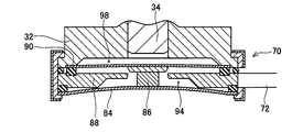
- Sectional view of power storage device Diagram showing the current interrupter when the terminals and electrodes are energized
- Diagram showing the current interrupter when the terminals and electrodes are not energized
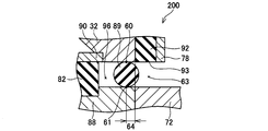
- the figure which expands and shows the part 200 enclosed with the dotted line of FIG. 2A.
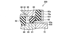
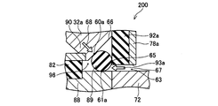
- the figure which shows the other example of the seal structure for preventing a liquid junction The figure which shows the further another example of the seal structure for preventing a liquid connection.
- the seal member may be one member disposed along the outer peripheral portion of the first current-carrying member or the second current-carrying member and looping around the outer peripheral portion. According to such a configuration, since the seal member is constituted by one member which goes around the outer peripheral portion of the first current-carrying member or the second current-carrying member, it is easy to assemble the two current-carrying members and the seal member. it can.
- the current interrupting device disclosed in the present specification further includes an insulating member provided in the first space between the first current-passing member and the second current-passing member, and in contact with the first current-passing member and the second current-passing member. Good. According to such a configuration, when the current supply is cut off, the insulation state between the first current supply member and the second current supply member can be favorably maintained.
- Power storage device 100 is a lithium ion secondary battery which is a type of secondary battery.
- the power storage device 100 includes a case 4, an electrode assembly 2, a negative electrode terminal 30 as an electrode terminal, a positive electrode terminal 10, and a current interrupting device 70.
- the case 4 is made of metal and has a substantially rectangular parallelepiped shape.
- the electrode assembly 2 and the current interrupting device 70 are housed inside the case 4.
- the inside of the case 4 is filled with an electrolytic solution.
- the negative electrode terminal 30 and the positive electrode terminal 10 are exposed to the outside of the case 4. Through holes 4 b and 4 c are formed in the upper surface 4 a of the case 4.
- the negative electrode terminal 30 passes through the through hole 4b, and the positive electrode terminal 10 passes through the through hole 4c.
- An insulating first seal member 42 is attached to the through hole 4 b.
- An insulating second seal member 22 is attached to the through hole 4c.
- the shape of the case 4 is not limited, and may be, for example, a cylindrical shape, a rectangular solid shape, or a sheet shape formed of a film.
- the negative electrode terminal 30 includes an outer nut 36, an inner nut 32 and a bolt 34.
- the external nut 36 is used for connection between the negative electrode terminal 30 and a negative electrode wiring (not shown).
- the internal nut 32 is attached to the first seal member 42. A part of the inner nut 32 passes through the through hole 4 b.
- the bolt 34 is fastened to the internal nut 32.
- a third seal member 40 intervenes between the bolt 34 and the case 4.
- the negative electrode terminal 30 is insulated from the case 4 by the seal members 40 and 42.
- the internal nut 32 is electrically connected to the negative electrode lead 44 via the current interrupting device 70 and the connection terminal 72.
- the negative electrode lead 44 is insulated from the case 4 by the first seal member 42.
- the negative electrode terminal 30 is electrically connected to the negative electrode of the electrode assembly 2 through the current interrupting device 70, the connection terminal 72 and the negative electrode lead 44.
- the current interrupting device 70 will be described later.
- the positive electrode terminal 10 includes an outer nut 16, an inner nut 12, and a bolt 14.
- the external nut 16 is used for connection between the positive electrode terminal 10 and the positive electrode wiring (not shown).
- the internal nut 12 is attached to the second seal member 22. A portion of the inner nut 12 passes through the through hole 4c.
- the bolt 14 is fastened to the internal nut 12.
- a fourth seal member 20 intervenes between the bolt 14 and the case 4.
- the positive electrode terminal 10 is insulated from the case 4 by the seal members 20 and 22.
- the positive electrode lead 24 is fixed to the internal nut 12.
- the internal nut 12 and the positive electrode lead 24 are electrically connected.
- the positive electrode lead 24 is insulated from the case 4 by the second seal member 22.
- the positive electrode terminal 10 is electrically connected to the positive electrode of the electrode assembly 2 through the positive electrode lead 24.
- the electrode assembly 2 is provided with a projection 2 a that protrudes to the upper surface 4 a side of the case 4.
- the electrode assembly 2 includes a positive electrode, a negative electrode, and a separator interposed between the positive electrode and the negative electrode. Illustration of the positive electrode, the negative electrode and the separator is omitted.
- the negative electrode includes a negative electrode current collector and a negative electrode active material layer formed on the negative electrode current collector.
- the negative electrode has a negative current collecting tab 46 at its end.
- the negative electrode current collection tab 46 is not coated with the negative electrode active material layer.
- the positive electrode has a positive electrode current collector and a positive electrode active material layer formed on the positive electrode current collector.
- the positive electrode has a positive current collecting tab 26 at its end.
- the positive electrode current collector tab 26 is not coated with the positive electrode active material layer.
- the material active material, binder, conductive additive and the like contained in the active material layer, and materials used for electrodes of known power storage devices and the like can be used.
- the positive electrode current collector for example, aluminum (Al), nickel (Ni), titanium (Ti), stainless steel or a composite material or alloy thereof can be used.
- aluminum or a composite material or alloy containing aluminum is preferable.
- any material can be used as long as lithium ions can enter and leave the positive electrode active material, and Li 2 MnO 3 , Li (NiCoMn) 0.33 O 2 , Li (NiMn) 0.5 O 2 , LiMn 2 O 4, LiMnO 2, LiNiO 2 , and LiCoO 2, LiNi 0.8 Co 0.15 Al 0.05 O 2, Li 2 MnO 2, LiMn 2 O 4 or the like can be used.
- an alkali metal such as lithium or sodium, sulfur or the like can also be used as the positive electrode active material. These may be used singly or in combination of two or more.
- the positive electrode active material is applied to the positive electrode current collector together with a conductive material, a binder and the like as necessary.
- the negative electrode current collector aluminum, nickel, copper (Cu), etc., or a composite material or alloy thereof can be used. In particular, copper or a composite material or alloy containing copper is preferable.
- the negative electrode active material a material in which lithium ions can enter and leave can be used. Alkali metals such as lithium (Li) and sodium (Na), transition metal oxides containing alkali metals, natural graphite, mesocarbon microbeads, highly oriented graphite, hard carbon, carbon materials such as soft carbon, silicon alone or silicon Containing alloys or silicon-containing oxides can be used.
- the negative electrode active material is applied to the negative electrode current collector together with a conductive material, a binder and the like as necessary.
- porous material which has insulation can be used for a separator.
- a porous film made of a polyolefin resin such as polyethylene (PE) or polypropylene (PP), or a woven or non-woven fabric made of polypropylene, polyethylene terephthalate (PET), methyl cellulose or the like can be used.
- the electrolytic solution is preferably a non-aqueous electrolytic solution in which a supporting salt (electrolyte) is dissolved in a non-aqueous solvent.
- Solvents containing a linear ester such as ethylene carbonate (EC), propylene carbonate (PC), dimethyl carbonate (DMC), diethyl carbonate (DEC), ethyl methyl carbonate (EMC) as a non-aqueous solvent, ethyl acetate, Solvents such as methyl propironate or mixtures thereof can be used.
- a supporting salt electrolyte
- LiPF 6 LiBF 4
- LiAsF 6 or the like can be used as the support salt (electrolyte).
- the current interrupting device 70 will be described with reference to FIGS. 2A and 2B.
- the current interrupting device 70 is connected between the negative electrode terminal 30 and the negative electrode current collection tab (negative electrode) 46.
- the current interrupting device 70 may be connected between the positive electrode and the positive electrode terminal 10, or may be connected between both the negative electrode and the negative electrode terminal 30, and between the positive electrode and the positive electrode terminal 10. Good. 2A and 2B, illustration of the sealing member 42 interposed between the negative electrode terminal 30 and the case 4 is omitted.
- the current interrupting device 70 includes a first reverse plate 84 made of metal, a breaking plate 88 made of metal, a second reverse plate 90 made of metal, and a support member 92 having an insulating property.
- the support member 92 supports the first reversing plate 84, the break plate 88 and the second reversing plate 90. That is, the support member 92 is fitted to the first reversing plate 84, the breaking plate 88 and the second reversing plate 90 from the outside, and the first reversing plate 84, the breaking plate 88 and the second reversing plate 90 are stacked. I support it.
- a metal plate member 78 is attached to the outer peripheral surface of the support member 92.
- the plate member 78 is formed on the outer peripheral surface of the support member 92 in a state where the lower end portion of the first reverse plate 84, the rupture plate 88, the second reverse plate 90, and the inner nut 32 is sandwiched from above and below. It is crimped. Thereby, the current interrupting device 70 is attached to the internal nut 32.
- An opening 93 is formed on the outer peripheral surface of the support member 92 and the plate member 78 in a part of the circumferential direction. The opening 93 communicates with the space in the case 4, and the connection terminal 72 is disposed in the opening 93.
- the breaking plate 88 disposed inside the support member 92 and the plate member 78 and the negative electrode lead 44 are connected via the connection terminal 72.
- the first reversing plate 84 is a circular plate and is disposed below the breaking plate 88.
- the lower surface of the outer peripheral edge of the first reversing plate 84 is supported by the support member 92 over the entire circumference.
- An insulating member 80 is disposed on the upper surface of the outer peripheral edge of the first reversing plate 84.
- the insulating member 80 is a ring-shaped member, and insulates the first reversing plate 84 and the breaking plate 88.
- a protrusion 86 is provided on the upper surface of the first reversing plate 84, and the protrusion 86 is located at the center of the first reversing plate 84.
- the projection 86 projects upward toward the breaking plate 88.
- a gap is formed between the protrusion 86 and the central portion 88 b of the breaking plate 88.
- the pressure of the space in the case 4 acts on the lower surface of the first reversing plate 84, and the pressure of the space 94 between the first reversing plate 84 and the breaking plate 88 acts on the upper surface of the first reversing plate 84. Do. Since the space 94 and the space in the case 4 are sealed, when the pressure in the space in the case 4 is high, the pressure acting on the upper surface and the lower surface of the first reversing plate 84 will be different.
- the breaking plate 88 is a circular plate and is disposed between the first reversing plate 84 and the second reversing plate 90.
- the connection terminal 72 is connected to a part of the outer peripheral portion of the breaking plate 88.
- a groove 88 a is formed at the center of the lower surface of the breaking plate 88.
- the groove 88a is formed in a circular shape in bottom view.
- the cross-sectional shape of the groove part 88a is carrying out the triangle shape which becomes convex upwards.
- the fracture plate 88 is divided by the groove 88a into a central portion 88b surrounded by the groove 88a and an outer peripheral portion 88c located on the outer peripheral side of the groove 88a.
- the plate thickness of the central portion 88b is thin, and the plate thickness of the outer peripheral portion 88c is thick.
- the second reversing plate 90 is a circular plate and is disposed above the breaking plate 88.
- the central portion of the second reversing plate 90 is downwardly convex in the state shown in FIG. 2A and is fixed to the central portion 88 b of the breaking plate 88.
- the outer peripheral portion of the second reversing plate 90 is electrically connected to the internal nut 32. Therefore, the negative electrode terminal 30 is connected to the electrode assembly 2 through the second reverse plate 90, the breaking plate 88, the connection terminal 72 and the negative electrode lead 44.
- a space 98 is formed between the upper surface of the second reversing plate 90 and the lower surface of the inner nut 32, and the space 98 is sealed from the space in the case 4.
- An insulating member 82 is disposed between the second reverse plate 90 and the breaking plate 88.
- the insulating member 82 is a ring-shaped member and is in contact with the outer peripheral portion of the second reversing plate 90 and the outer peripheral portion of the breaking plate 88 to insulate both of them.
- a seal member 89 is further disposed between the rupture plate 88 and the outer peripheral portion of the internal nut 32.
- the seal member 89 is a ring-shaped member having a circular cross section, and is disposed outside the insulating member 82.
- the seal member 89 is in contact with the lower surface of the inner nut 32 and the upper surface of the breaking plate 88, and makes a circuit along the outer circumference of the inner nut 32 and the breaking plate 88.
- the seal member 89 seals (seals) the gap between the internal nut 32 and the breaking plate 88.
- the space located below the second reversing plate 90 and the inner nut 32 and above the breaking plate 88 is separated by the seal member 89 into the inner space 96 and the outer space 63 (see FIG. 3). ing. Therefore, it can be said that the insulating member 82 is disposed in the space 96 inside the sealing member 89. Further, as described above, the space 63 outside the seal member 89 communicates with the space in the case 4 through the opening 93 formed in the support member 92 and the plate member 78. On the other hand, since the space 96 is sealed from the space 63 by the seal member 89, the space 96 and the space in the case 4 do not communicate with each other.
- the seal member 89 is compressed between the inner nut 32 and the break plate 88. Further, the internal nut 32 is in contact at the first contact portion 60 of the seal member 89. Furthermore, the breaking plate 88 is in contact at the second contact portion 61 of the seal member 89. As apparent from FIG. 3, in a plan view of the current interrupting device 70, the region 64 outside the first contact portion 60 and the second contact portion 61 within the range where the internal nut 32 and the fracture plate 88 are opposed. The sealing member 89 is present in the whole. That is, the seal member 89 protrudes outward beyond the outer peripheral edge of the inner nut 32 and the outer peripheral edge of the rupture plate 88 throughout the circumferential direction.
- the internal nut 32 and the breaking plate 88 do not directly oppose each other, and the lower surface of the internal nut 32 faces the upper surface of the sealing member 89.
- the upper surface of the rupture plate 88 faces the lower surface of the seal member 89.
- the negative electrode terminal 30 and the negative electrode current collecting tab 46 are energized, and the positive electrode terminal 10 and the positive electrode current collecting tab 26 (negative electrode) are energized. ing. Therefore, current flows between the negative electrode terminal 30 and the positive electrode terminal 10.
- the breaking plate 88 breaks at the groove 88a, and the outer peripheral portion 88c of the breaking plate 88 and the second reverse plate 90 ( The conduction path between the inner nuts 32) is interrupted.
- the pressure acting on the lower surface of the first reversing plate 84 rises (the state of FIG. 2A).
- the pressure acting on the upper surface of the first reversing plate 84 (that is, the pressure of the space 94) is not affected by the pressure increase in the case 4 and does not change. For this reason, when the internal pressure in the case 4 exceeds the predetermined value, the first reversing plate 84 is reversed, and the convex downward state changes to the convex upward state.
- the first reversing plate 84 When the first reversing plate 84 is reversed, the projection 86 of the first reversing plate 84 collides with the central portion 88b of the breaking plate 88, and the breaking plate 88 breaks at the groove 88a. Then, the second reverse plate 90 is also reversed according to the displacement of the first reverse plate 84, and the second reverse plate 90, the central portion of the rupture plate 88, and the first reverse plate 84 are displaced upward (the state of FIG. 2B ). As a result, the conduction path connecting the breaking plate 88 and the second reversing plate is cut off, and the conduction between the electrode assembly 2 and the negative electrode terminal 30 is cut off.
- the breaking plate 88 is broken at the groove 88a (the state shown in FIG. 2B)
- the negative electrode terminal 30 is connected to the external device, and the breaking plate 88 is connected to the negative electrode of the electrode assembly 2. Therefore, a large voltage may be applied between the negative electrode terminal 30 (that is, the internal nut 32) and the breaking plate 88.
- the space 63 communicates with the space in the case 4, there is a possibility that the electrolytic solution intrudes into the space 63.
- the seal member 89 covers the entire area 64 outside the first contact portion 60 and the second contact portion 61 within the range where the internal nut 32 and the breaking plate 88 are opposed. Exists.
- the seal member 89 suppresses the liquid dripping between the internal nut 32 and the breaking plate 88 and seals the gap between the internal nut 32 and the breaking plate 88. For this reason, since the sealing member 89 which is a single member performs a plurality of functions (a liquid drip prevention function, a sealing function), the configuration of the current interrupting device 70 can be simplified.
- the internal nut 32 and the second reversing plate 90 are an example of the “first conducting member”, the breaking plate 88 is an example of the “second conducting member”, and the space 96 is an example of the “first space”. 63 is an example of the "second space”.
- the seal member 89 contacts only the two members of the internal nut 32 and the breaking plate 88, but the present invention is not limited to such a configuration.
- the seal member 89 in addition to the internal nut 32 and the breaking plate 88, the seal member 89 is in contact with the support member 92 a at the third contact portion 65.
- the seal member 89 is in contact with the internal nut 32, the rupture plate 88 and the support member 92a at three points of the first contact portion 60, the second contact portion 61 and the third contact portion 65. Therefore, the second space 63 is separated by the seal member 89 into the space 631 on the side of the first contact portion 60 and the space 632 on the side of the second contact portion. Therefore, the electrolytic solution that has entered the space 632 is prevented from entering the space 631 by the third contact portion 65, whereby liquid junction between the internal nut 32 and the fracture plate 88 can be prevented more reliably.
- the lower surface of the internal nut 32 and the upper surface of the fracture plate 88 face each other, and the seal member 89 is in contact with each surface at the positions parallel to each other.
- the configuration is not limited.
- a taper 66 is provided at an outer peripheral corner of the surface on the fracture plate 88 side of the inner nut 32a (a corner formed by the surface facing the fracture plate 88 and the outer periphery of the inner nut 32a).
- the seal member 89 is disposed to be in contact with the taper 66 of the internal nut 32a, and is in contact with the taper 66 at the first contact portion 60a.
- the seal member 89 is in contact with the breaking plate 88 at the second contact portion 61 a and is in contact with the support member 92 a at the third contact portion 65.
- this external force can be received by the taper 66.
- the balance of the force applied to the seal member 89 is maintained, and the proper positional relationship between the seal member 89, the internal nut 32a and the breaking plate 88 is maintained. Therefore, it is possible to prevent the function of preventing the liquid junction by the seal member 89 from being impaired.
- the cross-sectional shape of the seal member 89 provided in the embodiment described above is not limited to the perfect circular shape as shown in the drawings. For example, it may be elliptical or polygonal. Further, in the embodiment described above, the connecting member 72 and the breaking plate 88 are provided as separate members, but the connecting member 72 and the breaking plate 88 may be integrally formed.
- the structure of an electric current interruption apparatus is not restricted to such an example.
- the current interrupting device may be composed of one reversing plate and a breaking plate. That is, similarly to the current interrupting device shown in FIG. 2A, the broken plate and the reversing plate (corresponding to the second reversing plate) are provided so that the pressure in the case acts on the reversing plate.
- the internal pressure in the case acts on the lower surface of the reversing plate, and when the differential pressure of the pressure acting on the upper and lower surfaces of the reversing plate exceeds a predetermined value, the reversing plate reverses and the fracture plate breaks.
- the reversing member is disposed by arranging the seal member between the outer periphery of the breaking plate and the outer periphery of the reversing plate (the outer periphery of the inner nut). And the breakage of the rupture plate can be prevented.
- each of the first reversing plate and the second reversing plate may be any one as long as it can be deformed by receiving pressure, and is not limited to the one having a “reversing” structure.
- the technical elements described in the present specification or the drawings exhibit technical usefulness alone or in various combinations, and are not limited to the combinations described in the claims at the time of filing. Further, the techniques exemplified in the present specification or the drawings can achieve a plurality of purposes simultaneously, and achieving one of the purposes itself has technical utility.
Landscapes
- Chemical & Material Sciences (AREA)
- Chemical Kinetics & Catalysis (AREA)
- Electrochemistry (AREA)
- General Chemical & Material Sciences (AREA)
- Connection Of Batteries Or Terminals (AREA)
Abstract
本明細書は、遮断された導電部材の間に導電性異物が生成して液絡し再通電することを防止する電流遮断装置を提供する。電流遮断装置は、外部端子とケースに収容される電極組立体との間に接続され、互いに対向して配置された第1通電部材32aと第2通電部材88をそれぞれ有し、その間に絶縁性のシール部材89を有し、第1通電部材32aは外部端子と第2通電部材88は電極組立体とそれぞれ接続している。シール部材89は第1通電部材32aと第2通電部材88の間の空間をその内側と外側の空間に隔離し、外側の空間63はケース内の空間と連通している。平面視すると、シール部材89の第1通電部材32aと第2通電部材88の接触部より外側の領域全体にシール部材89が位置する。さらに第1通電部材32aの外周縁の角部にテーパ66が設けられ、シール部材89がそのテーパ66に接触している。
Description
本明細書は、電流遮断装置およびそれを用いた蓄電装置に関する技術を開示する。
蓄電装置には、蓄電装置が過充電され、あるいは、内部で短絡が発生したときに、ケース内の電極組立体とケースに設けられた外部端子とを接続する通電経路を遮断する電流遮断装置が装備されることがある。特開平08-185849号公報と特開平08-115715号公報の電流遮断装置は、内部端子板と、内部端子板と対向して配置された導電板を備えている。導電板の外周部は外部端子板に接続され、導電板の中央部は内部端子板の中央部に接続されている。また、内部端子板の外周部は電極組立体に接続されている。ケース内の圧力が上昇すると、導電板と内部端子板とが分離し、導電板と内部端子板との通電が遮断され、電極組立体と外部端子の間を流れる電流が遮断される。
この種の電流遮断装置では、導電板と内部端子板とが分離したときに、導電板と内部端子板の間に大きな電圧が印加されることがある。かかる場合、導電板と内部端子板とが対向する範囲において、両者の間にケース内の電解液が存在すると、その電解液から導電性異物が生成して液絡し、導電板と内部端子板とが再通電する虞がある。このため従来の電流遮断装置では、ケース内の電解液が導電板と内部端子板との間の隙間に侵入しないように2つのシール部材が設けられ、複雑な構造となっていた。すなわち、導電板と内部端子板の隙間に第1シール部材が設けられると共に、導電板の外周面と内部端子板の外周面に接する第2シール部材が配されていた。本明細書では、2つの通電部材間の液絡の防止を簡易な構造で実現する技術を提供する。
本明細書が開示する電流遮断装置は、ケースに設けられた外部端子と、ケースに収容される電極組立体とを接続する通電経路を、ケース内の内圧が所定値を超えた時に遮断する。この電流遮断装置は、外部端子と電気的に接続された第1通電部材と、第1通電部材と対向して配置され、電極組立体と電気的に接続された第2通電部材と、第1通電部材と第2通電部材との間に設けられ、第1通電部材と第2通電部材の間の隙間を封止する絶縁性のシール部材と、を備えている。第1通電部材と第2通電部材は、ケース内の圧力が所定値以下の時は互いに通電して通電経路の一部を形成する一方、ケース内の圧力が所定値を超えると互いに離間して通電経路を遮断する。シール部材は第1通電部材の外周縁の近傍に接触する第1接触部と、第2通電部材の外周縁に接触する第2接触部を有しており、第1通電部材と第2通電部材の間の空間を第1接触部および第2接触部より内側の第1空間と外側の第2空間とに隔離する。第2空間はケース内の空間と連通している。第1通電部材と第2通電部材とシール部材を平面視すると、第1通電部材と第2通電部材が対向する範囲内において、第1接触部および第2接触部より外側の領域全体にシール部材が位置する。さらに第1通電部材と第2通電部材の少なくとも一方は、第1通電部材と第2通電部材の他方と対向する対向面を有すると共に、その対向面とその外周面により形成される角部にテーパが設けられており、シール部材がそのテーパの形成された部分に接触している。ここで、平面視とは、第1通電部材と第2通電部材が互いに対向している面に対して垂直な方向から視ることを意味する。別言すれば、第1通電部材と第2通電部材の位置関係において、第2通電部材に対して第1通電部材が位置する側から視ること、若しくは、第1通電部材に対して第2通電部材が位置する側から視ることを意味する。
上記の電流遮断装置では、第1通電部材と第2通電部材の隙間がシール部材によって第1空間と第2空間に隔離され、第2空間がケース内の空間に連通している。このため、第2空間にはケース内の電解液が侵入する可能性がある。しかしながら第2空間では、第1通電部材と第2通電部材とが対向する範囲の全体にシール部材が位置し、第1通電部材と第2通電部材とが、その間に電解液が存在する状態で直接対向することが防止される。これによって、第1通電部材と第2通電部材の液絡が防止される。すなわち、第1通電部材と第2通電部材の間の第2空間に電解液が侵入しても、両者の間にシール部材が適切に配置されているため、両者の液絡を防止することができる。また、この電流遮断装置では、第1通電部材と第2通電部材の間への電解液の侵入が許容されるため、従来技術のように2つのシール部材を用いる必要がなく、簡易な構造で液絡を防止することができる。
さらに、上記の対向面とその外周面により形成される角部にテーパが設けられ、シール部材がテーパの形成された部分に接触している。このような構成によると、ケース内の内圧が上昇してその内圧がシール部材に作用した場合に、その内圧が作用しているシール部材をテーパが形成された部位で受け止めることができる。このため、第1通電部材と第2通電部材の間の適切な位置にシール部材を保持することができる。
以下、本明細書で開示する実施例の技術的特徴の幾つかを記す。なお、以下に記す事項は、各々単独で技術的な有用性を有している。
本明細書に開示する電流遮断装置では、シール部材は、第1通電部材または第2通電部材の外周部に沿って配置される共にその外周部を一巡する一つの部材であってもよい。このような構成によると、シール部材が第1通電部材または第2通電部材の外周部を一巡する一つの部材で構成されるため、2つの通電部材とシール部材の組付けを容易に行うことができる。
本明細書に開示する電流遮断装置では、第1通電部材と第2通電部材の間の第1空間に設けられ、第1通電部材と第2通電部材に接触する絶縁部材をさらに備えていてもよい。このような構成によると、通電が遮断されたときに、第1通電部材と第2通電部材の絶縁状態を良好に維持することができる。
(実施例)以下、第1実施例の蓄電装置100について説明する。蓄電装置100は、二次電池の一種であるリチウムイオン二次電池である。図1に示すように、蓄電装置100は、ケース4と、電極組立体2と、電極端子としての負極端子30、及び正極端子10と、電流遮断装置70を備えている。ケース4は、金属製であり、略直方体形状である。ケース4の内部には、電極組立体2と電流遮断装置70が収容されている。また、ケース4の内部は、電解液で満たされている。ケース4の上面4aにおいて、負極端子30と正極端子10が、ケース4の外部に露出している。ケース4の上面4aには、貫通孔4b、4cが形成されている。負極端子30が貫通孔4bを通過しており、正極端子10が貫通孔4cを通過している。貫通孔4bには、絶縁性の第1シール部材42が取り付けられている。貫通孔4cには、絶縁性の第2シール部材22が取り付けられている。なお、ケース4の形状に制限はなく、例えば、円筒状、直方体状、あるいは、フィルムで形成されているシート状であってもよい。
負極端子30は、外部ナット36と、内部ナット32と、ボルト34を備えている。外部ナット36は、負極端子30と負極配線(図示省略)との結線に用いられる。内部ナット32は、第1シール部材42に取り付けられている。内部ナット32の一部は、貫通孔4bを通過している。ボルト34は、内部ナット32に締結されている。ボルト34とケース4の間には、第3シール部材40が介在している。負極端子30は、シール部材40、42によってケース4から絶縁されている。内部ナット32は、電流遮断装置70及び接続端子72を介して負極リード44に電気的に接続されている。負極リード44は、第1シール部材42によってケース4から絶縁されている。負極端子30は、電流遮断装置70、接続端子72及び負極リード44を介して、電極組立体2の負極電極と通電している。電流遮断装置70については後述する。
正極端子10は、外部ナット16と、内部ナット12と、ボルト14を備えている。外部ナット16は、正極端子10と正極配線(図示省略)との結線に用いられる。内部ナット12は、第2シール部材22に取り付けられている。内部ナット12の一部は、貫通孔4cを通過している。ボルト14は、内部ナット12に締結されている。ボルト14とケース4の間には、第4シール部材20が介在している。正極端子10は、シール部材20、22によってケース4から絶縁されている。内部ナット12には、正極リード24が固定されている。内部ナット12と正極リード24は、電気的に接続している。正極リード24は、第2シール部材22によってケース4から絶縁されている。正極端子10は、正極リード24を介して、電極組立体2の正極電極と通電している。
(電極組立体)電極組立体2は、ケース4の上面4a側に突出する凸部2aを備えている。電極組立体2は、正極電極と、負極電極と、正極電極と負極電極の間に介在しているセパレータを備えている。正極電極、負極電極及びセパレータの図示は省略する。負極電極は、負極集電体と、負極集電体上に形成されている負極活物質層を有する。負極電極は、その端部に負極集電タブ46を有する。負極集電タブ46には、負極活物質層が塗布されていない。正極電極は、正極集電体と、正極集電体上に形成されている正極活物質層を有する。正極電極は、その端部に正極集電タブ26を有する。正極集電タブ26には、正極活物質層が塗布されていない。なお、活物質層に含まれる材料(活物質、バインダ、導電助剤等)には特に制限がなく、公知の蓄電装置等の電極に用いられる材料を用いることができる。
ここで、正極集電体には、例えば、アルミニウム(Al)、ニッケル(Ni)、チタン(Ti)、ステンレス鋼又はそれらの複合材料もしくは合金を用いることができる。特に、アルミニウム又はアルミニウムを含む複合材料もしくは合金であることが好ましい。また、正極活物質には、リチウムイオンが侵入及び脱離可能な材料であればよく、Li2MnO3、Li(NiCoMn)0.33O2、Li(NiMn)0.5O2、LiMn2O4、LiMnO2、LiNiO2、LiCoO2、LiNi0.8Co0.15Al0.05O2、Li2MnO2、LiMn2O4等を使用することができる。また、正極活物質としてリチウム、ナトリウム等のアルカリ金属、あるいは、硫黄などを用いることもできる。これらは1種単独で使用してもよいし、2種以上を併用して用いてもよい。正極活物質は、必要に応じて導電材,結着剤等とともに正極集電体に塗布される。
一方、負極集電体としては、アルミニウム、ニッケル、銅(Cu)等、又はそれらの複合材料もしくは合金等を使用することができる。特に、銅又は銅を含む複合材料もしくは合金であることが好ましい。また、負極活物質としては、リチウムイオンが侵入及び脱離可能な材料を用いることができる。リチウム(Li)、ナトリウム(Na)等のアルカリ金属、アルカリ金属を含む遷移金属酸化物、天然黒鉛、メソカーボンマイクロビーズ、高配向性グラファイト、ハードカーボン、ソフトカーボン等の炭素材料、シリコン単体又はシリコン含有合金又はシリコン含有酸化物を使用することができる。負極活物質は、必要に応じて導電材,結着剤等とともに負極集電体に塗布される。
なお、セパレータは、絶縁性を有する多孔質を用いることができる。セパレータとしては、ポリエチレン(PE)、ポリプロピレン(PP)等のポリオレフィン系樹脂からなる多孔質フィルム、あるいは、ポリプロピレン、ポリエチレンテレフタレート(PET)、メチルセルロース等からなる織布または不織布を使用することができる。
また、電解液は、非水系の溶媒に支持塩(電解質)を溶解させた非水電解液であることが好ましい。非水系の溶媒として、エチレンカーボネート(EC)、プロピレンカーボネート(PC)、ジメチルカーボネート(DMC)、ジエチルカーボネート(DEC)、エチルメチルカーボネート(EMC)等の鎖状エステルを含んでいる溶媒、酢酸エチル、プロピロン酸メチルなどの溶媒、又はこれらの混合液を使用することができる。また、支持塩(電解質)として、例えば、LiPF6、LiBF4、LiAsF6等を使用することができる。
(電流遮断装置)図2Aおよび図2Bを参照して、電流遮断装置70について説明する。電流遮断装置70は、負極端子30と負極集電タブ(負極電極)46の間に接続されている。なお、電流遮断装置70は、正極電極と正極端子10の間に接続してもよいし、負極電極と負極端子30の間、及び、正極電極と正極端子10の間の双方に接続してもよい。なお、図2A、図2Bでは、負極端子30とケース4との間に介在しているシール部材42の図示を省略している。
図2Aに示すように電流遮断装置70は、金属製の第1反転板84と、金属製の破断板88と、金属製の第2反転板90と、絶縁性を有する支持部材92を備えている。支持部材92は、第1反転板84と破断板88と第2反転板90を支持している。すなわち、支持部材92は、第1反転板84と破断板88と第2反転板90に対して外側より嵌め込まれ、第1反転板84と破断板88と第2反転板90を積層した状態で支持している。支持部材92の外周面には、金属製の板材78が取付けられている。具体的には、支持部材92が第1反転板84、破断板88、第2反転板90、及び内部ナット32の下端部を上下から挟み込んだ状態で、板材78が支持部材92の外周面にカシメられている。これにより、電流遮断装置70が内部ナット32に取付けられている。なお、支持部材92及び板材78の外周面には、周方向の一部において開口93が形成されている。開口93はケース4内の空間と連通しており、その開口93内には接続端子72が配置されている。これによって、支持部材92及び板材78の内部に配置される破断板88と負極リード44とが接続端子72を介して接続されている。
第1反転板84は、円形状の板材であり、破断板88の下方に配置されている。第1反転板84の外周縁の下面は、全周に亘って支持部材92に支持されている。第1反転板84の外周縁の上面には絶縁部材80が配置されている。絶縁部材80は、リング状の部材であり、第1反転板84と破断板88とを絶縁している。また、第1反転板84の上面には突部86が設けられ、突部86は第一反転板84の中央に位置している。突部86は、破断板88に向かって上方に突出している。図2Aに示す状態で、突部86と破断板88の中央部88bとの間には隙間が形成されている。なお、第1反転板84の下面にはケース4内の空間の圧力が作用し、第1反転板84の上面には、第1反転板84と破断板88の間の空間94の圧力が作用する。空間94とケース4内の空間とはシールされているため、ケース4内の空間の圧力が高くなると、第1反転板84の上面と下面に作用する圧力は相違することとなる。
破断板88は、円形状の板材であり、第1反転板84と第2反転板90の間に配置されている。破断板88の外周部の一部に接続端子72が接続されている。破断板88の下面の中央には溝部88aが形成されている。溝部88aは、底面視すると円形状に形成されている。また、図2Aに示すように、溝部88aの断面形状は上方に凸となる三角形状をしている。溝部88aが形成されることで、溝部88aが形成された位置における破断板88の機械的強度は、溝部88a以外の位置における破断板88の機械的強度よりも低くされている。破断板88は、溝部88aによって、溝部88aで囲まれた中央部88bと、溝部88aの外周側に位置する外周部88cに区分されている。中央部88bの板厚は薄く、外周部88cの板厚は厚くされている。
第2反転板90は、円形状の板材であり、破断板88の上方に配置されている。第2反転板90の中央部は、図2Aに示す状態では下方に凸となり、また、破断板88の中央部88bに固定されている。第2反転板90の外周部は、内部ナット32に電気的に接続されている。したがって、負極端子30は、第2反転板90、破断板88、接続端子72及び負極リード44を介して電極組立体2に接続されている。第2反転板90の上面と内部ナット32の下面の間には空間98が形成され、空間98はケース4内の空間からシールされている。第2反転板90と破断板88の間には、絶縁部材82が配置されている。絶縁部材82は、リング状の部材であり、第2反転板90の外周部と破断板88の外周部とに接触し、両者を絶縁している。
ここで、本実施例では、破断板88と内部ナット32の外周部の間にはシール部材89がさらに配置されている。シール部材89は、断面円形のリング状の部材であり、絶縁部材82の外側に配置されている。シール部材89は、内部ナット32の下面及び破断板88の上面に接触し、内部ナット32及び破断板88の外周部に沿って一巡している。シール部材89は、内部ナット32と破断板88との間の隙間を封止(シール)している。したがって、第2反転板90と内部ナット32の下方で、かつ、破断板88の上方に位置する空間は、シール部材89によって内側の空間96と、外側の空間63(図3参照)に隔離している。このため、絶縁部材82は、シール部材89より内側の空間96内に配置されているということができる。また、上述したように、シール部材89より外側の空間63は、支持部材92及び板材78に形成された開口93を介してケース4内の空間と連通している。一方、空間96はシール部材89によって空間63からシールされるため、空間96とケース4内の空間とが連通することはない。
図3に示すように、シール部材89は内部ナット32と破断板88の間で圧縮されている。また、内部ナット32は、シール部材89における第1接触部60で接触している。さらに、破断板88は、シール部材89における第2接触部61で接触している。図3から明らかなように、電流遮断装置70を平面視すると、内部ナット32と破断板88が対向している範囲内においては、第1接触部60および第2接触部61より外側の領域64の全体にシール部材89が存在している。すなわち、シール部材89は、周方向の全域において、内部ナット32の外周縁及び破断板88の外周縁より外側に突出している。このため、第1接触部60および第2接触部61より外側の領域64では、内部ナット32と破断板88が直接対向することはなく、内部ナット32の下面はシール部材89の上面に対向し、破断板88の上面はシール部材89の下面に対向している。
上述した蓄電装置100においては、図2Aに示す状態では、負極端子30と負極集電タブ46(負極電極)が通電しており、正極端子10と正極集電タブ26(負極電極)が通電している。そのため、負極端子30と正極端子10の間が通電している。ケース4内の内圧が上昇して予め設定された所定値を超えると、図2Bに示すように、破断板88が溝部88aで破断し、破断板88の外周部88cと第2反転板90(内部ナット32)の間の通電経路が遮断される。すなわち、ケース4内の内圧が上昇すると、第1反転板84の下面に作用する圧力が上昇する(図2Aの状態)。第1反転板84の上面に作用する圧力(すなわち、空間94の圧力)は、ケース4内の圧力上昇の影響を受けることはなく変化しない。このため、ケース4内の内圧が所定値を超えると、第1反転板84が反転して、下方に凸な状態から上方に凸な状態に変化する。第1反転板84が反転すると、第1反転板84の突部86が破断板88の中央部88bに衝突し、破断板88が溝部88aで破断する。すると、第1反転板84の変位に応じて第2反転板90も反転し、第2反転板90、破断板88の中央部、及び第1反転板84が上方に変位する(図2Bの状態)。これによって、破断板88と第2反転板を接続する通電経路が遮断され、電極組立体2と負極端子30との間の通電が遮断される。
破断板88が溝部88aで破断した状態(図2Bに示す状態)となっても、負極端子30は外部機器に接続されており、破断板88は電極組立体2の負極に接続されている。このため、負極端子30(すなわち、内部ナット32)と破断板88の間に大きな電圧が印加されることがある。また、空間63はケース4内の空間に連通しているため、空間63内に電解液が侵入する可能性がある。しかしながら、本実施例の電流遮断装置70では、内部ナット32と破断板88が対向している範囲内において、第1接触部60および第2接触部61より外側の領域64の全体にシール部材89が存在している。このため、内部ナット32と破断板88の間に大きな電圧が印加されても、電解液から導電性異物が生成することが抑制される。その結果、内部ナット32と破断板88とが液洛し、内部ナット32と破断板88とが再び通電することを抑制することができる。
なお、上述した電流遮断装置70では、シール部材89によって、内部ナット32と破断板88との液洛の抑制と、内部ナット32と破断板88との隙間のシールを行う。このため、単一の部材であるシール部材89によって複数の機能(液洛防止機能、シール機能)を果たすため、電流遮断装置70の構成を簡易にすることができる。
最後に、上述した実施例と請求の範囲に記載の対応関係を説明する。内部ナット32と第2反転板90が「第1通電部材」の一例であり、破断板88が「第2通電部材」の一例であり、空間96が「第1空間」の一例であり、空間63が「第2空間」の一例である。
なお、上述した実施例では、シール部材89が内部ナット32と破断板88の2つの部材にのみ接触していたが、このような構成には限らない。例えば図4に示す例では、内部ナット32と破断板88に加え、シール部材89が支持部材92aに第3接触部65で接触している。これにより、シール部材89は第1接触部60と第2接触部61と第3接触部65の3ヶ所で、内部ナット32と破断板88と支持部材92aに接触している。よって、第2空間63はシール部材89により、第1接触部60側の空間631と第2接触部側の空間632に隔離される。それゆえ、空間632に侵入した電解液は第3接触部65により空間631に侵入することが抑制され、よって内部ナット32と破断板88の間の液絡をより確実に防止することができる。
また、上述した実施例では内部ナット32の下面と破断板88の上面とが対向しており、これらの面の互いに平行となる位置でシール部材89が各面に接触していたが、このような構成には限らない。例えば図5に示す例では、内部ナット32aの破断板88側の面の外周角部(破断板88と対向する面と内部ナット32aの外周面により形成される角部)にテーパ66が設けられている。シール部材89は内部ナット32aのテーパ66と接触するように配され、テーパ66と第1接触部60aで接触している。また、シール部材89は破断板88と第2接触部61aで接触し、支持部材92aと第3接触部65で接触している。ケース内の圧力が上昇し、シール部材89に第1空間96へと向う外力67が作用すると、この外力をテーパ66で受けることができる。これによって、シール部材89にかかる力のつり合いは保持され、シール部材89と内部ナット32aと破断板88との適切な位置関係が保持される。よって、シール部材89による液絡防止機能が損なわれることを防ぐことができる。
なお図4,5に示す例においては、図1に示す実施例と同一の構成部品には同一符号を付しているが、図1に示す実施例と構成が一部相違する部品には、図1に示す実施例の対応する部品と同一の符号に加えてaをさらに付している。
なお、上述した実施例で設けられるシール部材89の断面形状は図示にあるような真円形状には限らない。例えば楕円形状や多角形状であってもよい。また、上述した実施例では、接続部材72と破断板88が別部材で備えられていたが、接続部材72と破断板88が一体で形成されていてもよい。
また、上述した実施例は、2枚の反転板84,96を備えた電流遮断装置70であったが、電流遮断装置の構成はこのような例に限られない。例えば、電流遮断装置は、1枚の反転板と破断板により構成してもよい。すなわち、図2Aに示す電流遮断装置と同様に、破断板と反転板(第2反転板に相当)とを備え、反転板にケース内の圧力が作用するように構成する。この電流遮断装置では、反転板の下面にケース内の内圧が作用し、反転板の上面と下面に作用する圧力の差圧が所定値を超えると、反転板が反転して破断板が破断する。このような電流遮断装置においても、図1に示す実施例と同様に破断板の外周部と反転板の外周部(内部ナットの外周部)との間にシール部材を配置することで、反転板と破断板の液絡を防止することができる。
以上、本発明の具体例を詳細に説明したが、これらは例示に過ぎず、請求の範囲を限定するものではない。請求の範囲に記載の技術には、以上に例示した具体例を様々に変形、変更したものが含まれる。例えば、第1反転板、及び第2反転板は、それぞれ、圧力を受けて変形するものであればよく、「反転」する構造のものに限られない。また、本明細書または図面に説明した技術要素は、単独であるいは各種の組合せによって技術的有用性を発揮するものであり、出願時の請求項に記載の組合せに限定されるものではない。また、本明細書または図面に例示した技術は複数の目的を同時に達成し得るものであり、そのうちの一つの目的を達成すること自体で技術的有用性を持つものである。
Claims (4)
- ケースに設けられた外部端子と前記ケースに収容された電極組立体とを接続する通電経路を前記ケース内の内圧が所定値を超えた時に遮断する電流遮断装置であって
前記外部端子と電気的に接続された第1通電部材と、
前記第1通電部材と対向して配置され、前記電極組立体と電気的に接続された第2通電部材と、
前記第1通電部材と前記第2通電部材との間に設けられ、前記第1通電部材と前記第2通電部材の隙間を封止する絶縁性のシール部材と、を備え、
前記第1通電部材と前記第2通電部材は、前記ケース内の内圧が所定値以下の時は互いに通電して前記通電経路の一部を形成する一方、前記ケース内の内圧が所定値を超えると互いに離間して前記通電経路を遮断し、
前記シール部材は、前記第1通電部材の外周縁の近傍に接触する第1接触部と、前記第2通電部材の外周縁の近傍に接触する第2接触部を有しており、前記第1通電部材と前記第2通電部材の間の隙間を前記第1接触部および前記第2接触部より内側の第1空間と外側の第2空間とに離隔し、
前記第2空間は前記ケース内の空間と連通しており、
前記第1通電部材と前記第2通電部材と前記シール部材を平面視すると、前記第1通電部材と前記第2通電部材が対向する範囲内において、前記第1接触部および前記第2接触部より外側の領域全体に前記シール部材が位置しており、
前記第1通電部材と前記第2通電部材の少なくとも一方は、前記第1通電部材と前記第2通電部材の他方と対向する対向面を有すると共に、その対向面と外周面により形成される角部にテーパが設けられており、
前記シール部材が前記テーパの形成された部分に接触している、
ことを特徴とする電流遮断装置。 - 前記シール部材は、前記第1通電部材または前記第2通電部材の外周部に沿って配置されると共にその外周部を一巡する一つの部材である請求項1に記載の電流遮断装置。
- 前記第1通電部材と前記第2通電部材の間の前記第1空間に設けられ、前記第1通電部材と前記第2通電部材に接触する絶縁部材をさらに備える、請求項1又は2に記載の電流遮断装置。
- 請求項1から3のいずれかに記載の電流遮断装置を備える蓄電装置。
Applications Claiming Priority (2)
| Application Number | Priority Date | Filing Date | Title |
|---|---|---|---|
| JP2013240223A JP5756843B2 (ja) | 2013-11-20 | 2013-11-20 | 電流遮断装置およびそれを用いた蓄電装置 |
| JP2013-240223 | 2013-11-20 |
Publications (1)
| Publication Number | Publication Date |
|---|---|
| WO2015076138A1 true WO2015076138A1 (ja) | 2015-05-28 |
Family
ID=53179405
Family Applications (1)
| Application Number | Title | Priority Date | Filing Date |
|---|---|---|---|
| PCT/JP2014/079740 Ceased WO2015076138A1 (ja) | 2013-11-20 | 2014-11-10 | 電流遮断装置およびそれを用いた蓄電装置 |
Country Status (2)
| Country | Link |
|---|---|
| JP (1) | JP5756843B2 (ja) |
| WO (1) | WO2015076138A1 (ja) |
Cited By (1)
| Publication number | Priority date | Publication date | Assignee | Title |
|---|---|---|---|---|
| CN105185946A (zh) * | 2015-09-08 | 2015-12-23 | 深圳市科达利实业股份有限公司 | 动力电池过大电流断电保护结构 |
Families Citing this family (2)
| Publication number | Priority date | Publication date | Assignee | Title |
|---|---|---|---|---|
| JP6547487B2 (ja) * | 2015-07-22 | 2019-07-24 | 株式会社豊田自動織機 | 蓄電装置モジュール |
| JP6597016B2 (ja) * | 2015-07-22 | 2019-10-30 | 株式会社豊田自動織機 | 蓄電装置 |
Citations (4)
| Publication number | Priority date | Publication date | Assignee | Title |
|---|---|---|---|---|
| JP2005276838A (ja) * | 2004-03-24 | 2005-10-06 | Samsung Sdi Co Ltd | キャップ組立体とこれを備えた二次電池 |
| WO2013125431A1 (ja) * | 2012-02-21 | 2013-08-29 | 株式会社豊田自動織機 | 蓄電装置 |
| JP2013175428A (ja) * | 2012-01-27 | 2013-09-05 | Sanyo Electric Co Ltd | 角形二次電池 |
| WO2013154166A1 (ja) * | 2012-04-12 | 2013-10-17 | 株式会社豊田自動織機 | 電流遮断装置及びそれを用いた蓄電装置 |
-
2013
- 2013-11-20 JP JP2013240223A patent/JP5756843B2/ja not_active Expired - Fee Related
-
2014
- 2014-11-10 WO PCT/JP2014/079740 patent/WO2015076138A1/ja not_active Ceased
Patent Citations (4)
| Publication number | Priority date | Publication date | Assignee | Title |
|---|---|---|---|---|
| JP2005276838A (ja) * | 2004-03-24 | 2005-10-06 | Samsung Sdi Co Ltd | キャップ組立体とこれを備えた二次電池 |
| JP2013175428A (ja) * | 2012-01-27 | 2013-09-05 | Sanyo Electric Co Ltd | 角形二次電池 |
| WO2013125431A1 (ja) * | 2012-02-21 | 2013-08-29 | 株式会社豊田自動織機 | 蓄電装置 |
| WO2013154166A1 (ja) * | 2012-04-12 | 2013-10-17 | 株式会社豊田自動織機 | 電流遮断装置及びそれを用いた蓄電装置 |
Cited By (1)
| Publication number | Priority date | Publication date | Assignee | Title |
|---|---|---|---|---|
| CN105185946A (zh) * | 2015-09-08 | 2015-12-23 | 深圳市科达利实业股份有限公司 | 动力电池过大电流断电保护结构 |
Also Published As
| Publication number | Publication date |
|---|---|
| JP2015099754A (ja) | 2015-05-28 |
| JP5756843B2 (ja) | 2015-07-29 |
Similar Documents
| Publication | Publication Date | Title |
|---|---|---|
| JP5757353B2 (ja) | 電流遮断装置およびそれを用いた蓄電装置 | |
| JP5609905B2 (ja) | 蓄電装置、二次電池および車両 | |
| CN106030860B (zh) | 电流断路装置以及具备该电流断路装置的蓄电装置 | |
| JP6260095B2 (ja) | 蓄電装置および二次電池 | |
| JP6220964B2 (ja) | 蓄電装置 | |
| US9806317B2 (en) | Electric storage device | |
| JP5756843B2 (ja) | 電流遮断装置およびそれを用いた蓄電装置 | |
| JP6052113B2 (ja) | 蓄電装置 | |
| JP6237892B2 (ja) | 蓄電装置 | |
| WO2015146365A1 (ja) | 電流遮断装置とそれを用いた蓄電装置 | |
| JP6498581B2 (ja) | 蓄電装置及び電流遮断装置 | |
| JP6565491B2 (ja) | 蓄電装置 | |
| JP6123648B2 (ja) | 蓄電装置 | |
| JP6194822B2 (ja) | 電流遮断装置およびそれを備えた蓄電装置 | |
| JP2017045660A (ja) | 蓄電装置 | |
| JP6152817B2 (ja) | 電流遮断装置およびそれを備えた蓄電装置 | |
| JPWO2016042940A1 (ja) | 電流遮断装置を備えた蓄電装置 | |
| JP6152783B2 (ja) | 電流遮断装置とそれを用いた蓄電装置 | |
| JP2015079631A (ja) | 電流遮断装置とそれを用いた蓄電装置 | |
| JP2018026367A (ja) | 蓄電装置および二次電池 | |
| JP6446966B2 (ja) | 電流遮断装置を備えた蓄電装置 | |
| JP6126513B2 (ja) | 電流遮断装置とそれを用いた蓄電装置 | |
| JP6314692B2 (ja) | 電流遮断装置とそれを用いた蓄電装置 | |
| JP6529881B2 (ja) | 蓄電装置 |
Legal Events
| Date | Code | Title | Description |
|---|---|---|---|
| 121 | Ep: the epo has been informed by wipo that ep was designated in this application |
Ref document number: 14864163 Country of ref document: EP Kind code of ref document: A1 |
|
| NENP | Non-entry into the national phase |
Ref country code: DE |
|
| 122 | Ep: pct application non-entry in european phase |
Ref document number: 14864163 Country of ref document: EP Kind code of ref document: A1 |