WO2015075992A1 - 探知装置、水中探知装置、及びレーダ装置 - Google Patents
探知装置、水中探知装置、及びレーダ装置 Download PDFInfo
- Publication number
- WO2015075992A1 WO2015075992A1 PCT/JP2014/072999 JP2014072999W WO2015075992A1 WO 2015075992 A1 WO2015075992 A1 WO 2015075992A1 JP 2014072999 W JP2014072999 W JP 2014072999W WO 2015075992 A1 WO2015075992 A1 WO 2015075992A1
- Authority
- WO
- WIPO (PCT)
- Prior art keywords
- detection device
- unit
- intensity spectrum
- receiving
- intensity
- Prior art date
- Legal status (The legal status is an assumption and is not a legal conclusion. Google has not performed a legal analysis and makes no representation as to the accuracy of the status listed.)
- Ceased
Links
Images




Classifications
-
- G—PHYSICS
- G01—MEASURING; TESTING
- G01S—RADIO DIRECTION-FINDING; RADIO NAVIGATION; DETERMINING DISTANCE OR VELOCITY BY USE OF RADIO WAVES; LOCATING OR PRESENCE-DETECTING BY USE OF THE REFLECTION OR RERADIATION OF RADIO WAVES; ANALOGOUS ARRANGEMENTS USING OTHER WAVES
- G01S15/00—Systems using the reflection or reradiation of acoustic waves, e.g. sonar systems
- G01S15/88—Sonar systems specially adapted for specific applications
- G01S15/96—Sonar systems specially adapted for specific applications for locating fish
-
- G—PHYSICS
- G01—MEASURING; TESTING
- G01S—RADIO DIRECTION-FINDING; RADIO NAVIGATION; DETERMINING DISTANCE OR VELOCITY BY USE OF RADIO WAVES; LOCATING OR PRESENCE-DETECTING BY USE OF THE REFLECTION OR RERADIATION OF RADIO WAVES; ANALOGOUS ARRANGEMENTS USING OTHER WAVES
- G01S15/00—Systems using the reflection or reradiation of acoustic waves, e.g. sonar systems
- G01S15/02—Systems using the reflection or reradiation of acoustic waves, e.g. sonar systems using reflection of acoustic waves
- G01S15/06—Systems determining the position data of a target
- G01S15/42—Simultaneous measurement of distance and other co-ordinates
-
- G—PHYSICS
- G01—MEASURING; TESTING
- G01S—RADIO DIRECTION-FINDING; RADIO NAVIGATION; DETERMINING DISTANCE OR VELOCITY BY USE OF RADIO WAVES; LOCATING OR PRESENCE-DETECTING BY USE OF THE REFLECTION OR RERADIATION OF RADIO WAVES; ANALOGOUS ARRANGEMENTS USING OTHER WAVES
- G01S7/00—Details of systems according to groups G01S13/00, G01S15/00, G01S17/00
- G01S7/52—Details of systems according to groups G01S13/00, G01S15/00, G01S17/00 of systems according to group G01S15/00
- G01S7/523—Details of pulse systems
- G01S7/526—Receivers
- G01S7/527—Extracting wanted echo signals
Definitions
- the present invention relates to a detection device, an underwater detection device, and a radar device for estimating the direction of arrival of an incoming wave.
- a detection device for estimating the arrival direction of transmitted ultrasonic waves or electromagnetic wave echoes (arrival waves) is known.
- the rank of the correlation matrix generated by the sampling data of the incoming wave can be recovered. It will be easier to separate incoming waves coming back.
- the spatial averaging method as described above can be applied to a case where a plurality of subarrays having the same arrangement can be taken out from the array (for example, an equally spaced linear array using the same elements).
- the above spatial averaging method cannot be applied to an array (for example, an array arranged along a ring) in which a plurality of sub-arrays having the same arrangement cannot be taken out even when translated.
- the present invention is for solving the above-mentioned problems, and its purpose is to separate incoming waves coming from a plurality of directions from each other.
- a detection device is a detection device that detects a target, and is arranged along each of at least two planes having different normal directions.
- a plurality of receiving elements each including at least two planar receiving arrays, and receiving units that receive echo signals at each of the plurality of receiving elements, and echo signals received by the respective planar receiving arrays,
- An intensity spectrum calculating unit that calculates an intensity spectrum for each of the at least two planar receiving arrays; and an echo image generating unit that generates an echo image by combining the plurality of intensity spectra calculated by the intensity spectrum calculating unit; I have.
- the echo image generation unit multiplies the intensity spectrum calculated by the intensity spectrum calculation unit by a weight set according to an orientation of each echo signal, and the weight is multiplied.
- the echo image is generated based on a value obtained by adding the intensity spectra to each other.
- the intensity spectrum calculation unit calculates the intensity spectrum based on a plurality of subarrays extracted from each of the planar receiving arrays.
- the detection device further includes a spatial average processing unit that performs a spatial average process using a spatial average method on a correlation matrix generated from each of the plurality of subarrays, and the intensity spectrum
- the calculation unit calculates the intensity spectrum based on a spatial average correlation matrix generated by performing the spatial average processing.
- the intensity spectrum calculation unit calculates the intensity spectrum by performing beam forming or adaptive beam forming based on the spatial average correlation matrix generated by the spatial average processing unit.
- the detection device further includes an eigenvector calculation unit that calculates an eigenvector of the spatial average correlation matrix generated by the spatial average processing unit, and the intensity spectrum calculation unit is calculated by the eigenvector calculation unit. The intensity spectrum is calculated based on the obtained eigenvector.
- the detection device includes a data matrix generation unit that generates a data matrix composed of the echo signals received by each of the planar reception arrays, and the data matrix generated by the data matrix generation unit A singular value decomposition unit that decomposes the singular value, and the intensity spectrum calculation unit calculates the intensity spectrum based on a singular vector obtained by singular value decomposition of the data matrix by the singular value decomposition unit To do.
- one side of at least one of the at least two planes is common to one side of the other of the at least two planes.
- the receiver is formed in a polyhedral shape including a plurality of planes including the at least two planes.
- an underwater detection device is an underwater detection device as any one of the above-described detection devices, and a plurality of ultrasonic waves as the plurality of receiving elements. And an array transducer as the receiving unit that receives the echo signal by each of the plurality of ultrasonic transducers.
- a radar apparatus is a radar apparatus as one of the detection apparatuses described above, and includes a plurality of antenna elements as the plurality of receiving elements.
- An array antenna as the receiving unit that includes the planar receiving array configured and receives the echo signal by each of the plurality of antenna elements.
- incoming waves coming from a plurality of directions can be separated from each other.
- FIG. 3 is a diagram when the transducer shown in FIG. 2 is viewed from above, and is a diagram for explaining a divided region that is a region detected by each receiving array. It is a graph which shows the weight multiplied by the echo intensity in each point of the division area corresponding to each receiving array. It is a figure which shows an example of the echo image displayed on an operation / display apparatus.
- FIG. It is a flowchart which shows operation
- An underwater detection device 1 as a detection device according to an embodiment of the present invention is used to detect an underwater target (for example, a school of fish).
- the underwater detection device 1 is installed in a ship such as a fishing boat.
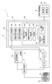
- FIG. 1 is a block diagram showing a configuration of an underwater detection device 1 according to an embodiment of the present invention.
- the underwater detection device 1 includes a transducer 10 (reception unit, array transducer), a transmission / reception switching unit 2, a transmitter 3, a receiver 4, and an operation / display device 5. .
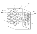
- FIG. 2 is a diagram schematically showing a schematic shape of the transducer 10 in the present embodiment.
- the transducer 10 is mounted on the bottom of a ship and exposed to the sea in order to transmit and receive ultrasonic waves.
- the transducer 10 includes a casing portion 15 formed in a rectangular tube shape, and a plurality of (in this embodiment, K) ultrasonic transducers A k attached to the casing portion 15.
- K 1, 2,..., K
- the ultrasonic transducer A k is transmits ultrasonic waves in water by converting electric signals into ultrasound, and converts the received ultrasonic electrical signal.
- Each ultrasonic transducer A k receives the reception signal x k at every predetermined time.
- the ultrasonic transducers Ak are attached to the casing unit 15 in a state of being arranged in a honeycomb shape as shown in FIG. 2 on each of the four side surfaces 11 to 14 of the casing unit 15.
- the receive array (planar receiver array) AR 1 ⁇ AR 4 is formed.
- the receiving array AR 1 is formed on the side surface 11
- the receiving array AR 2 is formed on the side surface 12
- the receiving array AR 3 is formed on the side surface 13
- the receiving array AR 4 is formed on the side surface 14. Is done.
- the plurality of ultrasonic transducers constituting each of the reception arrays AR 1 to AR 4 are arranged such that the distance between the centers of the adjacent ultrasonic transducers is a half wavelength of the ultrasonic waves.
- the reception array AR 3 and the reception array AR 4 are not shown in order to avoid complicated drawing.
- each of the receiving arrays AR 1 to AR 4 is arranged so as to face each of the azimuths that are equally divided into four in the sea.
- each of the receiving array AR 1 ⁇ AR 4 is the normal direction of the respective receiving array AR 1 ⁇ AR 4 out of the detection region (region spreading horizontally 360 ° around the transducer 10) Detect side areas. That is, each receiving array AR 1 ⁇ AR 4 is to detect a region of direction of respective receiving array AR 1 ⁇ AR 4 is headed.
- the transmission / reception switching unit 2 switches to a connection in which a transmission signal (pulse wave) is transmitted from the transmitter 3 to the transducer 10 at the time of transmission.
- the transmission / reception switching unit 2 switches to a connection in which an electrical signal converted from an ultrasonic wave by the transducer 10 is sent from the transducer 10 to the receiver 4 at the time of reception.
- the transmitter 3 generates a pulse wave based on the conditions set in the operation / display device 5. Moreover, transmitter 3, through the duplexer unit 2, so that the pulse wave is transmitted from each of the ultrasonic transducers A k for each predetermined time, and outputs the pulse wave with respect to the transducer 10. Each ultrasonic transducer Ak is driven by this pulse wave, and a pulse wave (ultrasonic wave) is radiated from the transducer 10 in each direction at a predetermined time.
- the receiver 4 includes an amplification unit 4a, an A / D conversion unit 4b, and a signal processing unit 20.
- Amplifying portion 4a amplifies the electrical signal transmitted through the transmission and reception switching unit 2 from each of the plurality of ultrasonic transducer A k, the A / D converts the received signal corresponding to each of the ultrasonic transducers A k Output to the unit 4b.
- the A / D conversion unit 4 b converts the reception signal (echo signal) output from the amplification unit 4 a into a complex digital signal by IQ detection or the like, and outputs the reception signal after conversion to the complex digital signal to the signal processing unit 20. To do.
- the signal processing unit 20 has an arrival direction estimation unit 21.
- the arrival direction estimation unit 21 processes the reception signal output from the A / D conversion unit 4b to generate an angle spectrum P ( ⁇ ), and based on the angle spectrum P ( ⁇ ), the arrival direction and intensity of the arrival wave The process which estimates is performed. Further, the signal processing unit 20 performs processing for generating a video signal based on the angle spectrum P ( ⁇ ). The signal processing unit 20 outputs the generated video signal to the operation / display device 5.
- the arrival direction estimation unit 21 will be described later in detail.
- the operation / display device 5 includes a display unit 5a and an operation unit 5b.
- the display unit 5a displays a video corresponding to the video signal on the display screen.
- the operation unit 5b has, for example, various input keys and the like, and is configured to be able to input various settings and various parameters necessary for transmission / reception of ultrasonic waves and video display.
- the arrival direction estimation unit 21 performs processing for processing the reception signal and estimating the arrival direction and intensity of the arrival wave.
- the arrival direction estimation unit 21 will be described in detail.
- the arrival direction estimation unit 21 includes a sub-array generation unit 22, a correlation matrix generation unit 23, a spatial average processing unit 24, and an arrival wave calculation unit 25.
- the arrival direction estimation unit 21 is configured using a device (computer) such as a CPU, FPGA, and memory (not shown).
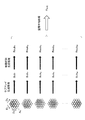
- FIG. 3 is a schematic diagram for explaining correlation matrix calculation and spatial averaging processing described below. With reference to FIG.1 and FIG.3, each component of the arrival direction estimation part 21 is demonstrated.
- the sub-array generation unit 22 receives a received data vector Sub 1 (sub 1 ) of a sub-array including an ultrasonic transducer and an ultrasonic transducer adjacent to the ultrasonic transducer.
- Sub-array received data vectors Sub 1 , Sub 2 ,..., Sub M are generated.
- Subarrays each receiving array AR 1 ⁇ AR 4 are generated from a plurality of ultrasonic transducers constituting the respective receiving array AR 1 ⁇ AR 4.
- the correlation matrix generation unit 23 calculates a correlation matrix Rsub m for each of the sub-array reception data vectors Sub m .
- the correlation matrix Rsub m is given by the following equation (1).
- the spatial average processing unit 24 is provided as a spatial average correlation matrix calculation unit that calculates a spatial average correlation matrix R AVE by performing spatial averaging of the correlation matrix Rsub m . Specifically, as shown in FIG. 3, the spatial average processing unit 24 performs processing (spatial average processing) for averaging correlation matrices (partial correlation matrices) Rsub 1 , Rsub 2 ,..., Rsub m . Thereby, the spatial average processing unit 24 calculates a spatial average correlation matrix R AVE .
- the incoming wave calculation unit 25 performs beam forming or adaptive beam forming based on the spatial average correlation matrix R AVE calculated by the spatial average processing unit 24, and performs calculation related to the incoming wave.
- the incoming wave calculation unit 25 includes an eigenvector calculation unit 26, an intensity spectrum calculation unit 27, a synthesis unit 28, an incoming wave direction and intensity calculation unit 29, and an echo image generation unit 30.
- the eigenvector calculation unit 26 calculates eigenvectors of the spatial average correlation matrix R AVE by numerical calculation using, for example, the MUSIC method.
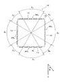
- FIG. 4 is a schematic view of the transducer shown in FIG. 2 viewed from above.
- the intensity spectrum calculation unit 27 calculates the intensity spectrum in the divided area that is the area detected by each of the reception arrays AR 1 to AR 4 by numerical calculation using the MUSIC method described above.
- the divided regions of the receiving array AR 1 ⁇ AR 4 is horizontal (AR 1 is 0 degree each receiving array AR 1 ⁇ AR 4 is directed, AR 2 is 90 degrees, AR 3 is 180 degrees and AR 4 is set to a range of ⁇ 60 degrees centered on 270 degrees). That is, each receiving array AR 1 ⁇ AR 4 is to detect a target existing within a range of ⁇ 60 degrees around the horizontal direction respective receiving array AR 1 ⁇ AR 4 is directed. Since the MUSIC method is known, a detailed description thereof will be omitted.
- the synthesizing unit 28 multiplies the echo intensity at each point of each divided region calculated by the intensity spectrum calculating unit 27 by a predetermined weight (weight) in accordance with the azimuth ⁇ of the echo signal to be calculated as the angular spectrum. Perform weighting. Then, the synthesis unit 28 calculates the final angular spectrum P ( ⁇ ) by synthesizing the weighted echo intensity for each point.
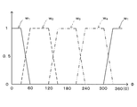
- FIG. 5 is a graph showing weights w 1 to w 4 to be multiplied with the outputs obtained from the respective reception arrays AR 1 to AR 4 .
- the synthesizer 28 multiplies the output obtained by the reception array AR 1 by the weight w 1 shown in FIG.
- the combining unit 28 multiplies the outputs obtained from the reception arrays AR 2 to AR 4 by the weights w 2 to w 4 shown in FIG.
- the synthesizer 28 sets the direction of the echo data for which the angle spectrum is to be calculated in the horizontal direction (AR 1 is 0 degrees, AR 2 is 90 degrees, AR 3) toward each of the receiving arrays AR 1 to AR 4. Is 180 degrees and AR 4 is 270 degrees) (in the range Z A in FIG. 4), the output obtained from each receiving array AR 1 to AR 4 is multiplied by weight 1 The output is the final echo intensity at each point.
- the synthesizing unit 28 has a range of ⁇ 15 degrees in the horizontal direction from the center of the two adjacent reception arrays AR 1 to AR 4 (range Z B in FIG. 4). , The intensity spectrum obtained in each of the two adjacent receiving arrays AR 1 to AR 4 is multiplied by each of the weights w 1 to w 4 shown in FIG. Then, the synthesis unit 28 sets a value obtained by adding the two values subjected to the weighting as a final output.
- the combining unit 28 combines the intensity spectra in the divided areas detected by the reception arrays AR 1 to AR 4 with each other, and detects the detection area that can be detected by the transducer 10 (360 degrees in the horizontal direction around the transducer 10).
- Angle spectrum P ( ⁇ ) in a range extending over.
- the arrival direction and intensity calculation unit 29 calculates the arrival direction and intensity of the arrival wave based on the angular spectrum P ( ⁇ ) generated by the synthesis unit 28. As a calculation example, the arrival direction and intensity calculation unit 29 estimates the arrival direction from the position (azimuth ⁇ ) of the peak (maximum value) of the angle spectrum P ( ⁇ ), and calculates the intensity of the arrival wave from the maximum value. To do. The arrival direction and intensity are displayed on the display unit 5 a of the operation / display device 5.
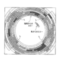
- FIG. 6 is a diagram illustrating an example of an echo image generated by the echo image generation unit 30.
- the echo image generation unit 30 generates an echo image based on the angle spectrum P ( ⁇ ) generated by the synthesis unit 28.
- the echo image is displayed on the display unit 5 a of the operation / display device 5.
- an arc-like echo image that seems to be caused by a single fish or a school of fish and an annular echo image caused by the sea floor are displayed at a position slightly away from the center of the image. Is done.
- the user looks at the echo image displayed on the display unit 5a and the arrival direction and intensity of the incoming wave, and information on the target (single fish, fish school, etc.) (position and distance from own ship, fish school state, etc.) ) Can be guessed.
- FIG. 7 is a flowchart for explaining the operation of the underwater detection device 1. Below, operation
- step S1 a pulse wave is transmitted from the transducer 10 toward the water.
- the transmitter 3 in step S1, so that the pulse wave is transmitted from each of the ultrasonic transducers A k, and outputs the transmission signal to the transducer 10.
- Pulse wave is transmitted every predetermined time, simultaneously from each of the ultrasonic transducers A k.
- step S2 the transducer 10 receives the reflected wave.
- An input vector x obtained from these reflected waves is output to the arrival direction estimation unit 21.
- step S3 the sub-array generation unit 22 generates a plurality of sub-array reception data vectors from the plurality of ultrasonic transducers A k that constitute each of the four reception arrays AR 1 to AR 4.
- step S4 the correlation matrix generation unit 23, as shown in FIG. 3, from each of the plurality of sub-arrays received data vector Sub m, to calculate the correlation matrix Rsub m corresponding to each sub-array receiving data vector Sub m .
- step S5 spatial averaging processing is performed. Specifically, in step S5, the spatial average processing unit 24 calculates the spatial average correlation matrix R AVE by averaging the correlation matrices Rsub 1 , Rsub 2 ,..., Rsub M as shown in FIG. .
- step S6 the eigenvector calculation unit 26 calculates an eigenvector of the spatial average correlation matrix.
- step S7 the intensity spectrum calculation unit 27 calculates the echo intensity at each point in each divided area detected by each reception array AR 1 to AR 4 by numerical calculation using the MUSIC method.
- step S8 the combining unit 28 performs weighting by multiplying the echo intensity at each point in each divided region by the weight shown in FIG. 5 according to the direction of the echo signal. By combining the echo intensities, the final angular spectrum P ( ⁇ ) is calculated.
- step S9a the arrival direction and intensity calculation unit 29 calculates the arrival direction and intensity of the incoming wave based on the angular spectrum P ( ⁇ ) generated by the synthesis unit 28.
- step S9b the echo image generation unit 30 generates an echo image based on the angle spectrum P ( ⁇ ) generated by the synthesis unit 28.
- the arrival direction and intensity of the incoming wave calculated in step S9a and the echo image generated in step S9b are displayed on the display unit 5a of the operation / display device 5.
- a plurality of ultrasonic transducers Ak are arranged along the side surfaces 11 to 14 of the casing portion 15 formed in a square cylinder shape.
- the sub-array can be translated in a plurality of directions (D 1 , D 2 , and D 3 directions in FIG. 3 in this embodiment).
- more subarrays can be extracted than in the conventional case, so that the rank of the correlation matrix can be easily recovered, and incoming waves coming from a plurality of directions can be easily separated from each other.
- the range of ⁇ 45 ° around the horizontal direction in which the receiving array AR 1 ⁇ AR 4 is directed, all over the divided regions Consider a case where the echo intensity at a point is performed only by the receiving array corresponding to each divided region. Then, as shown in FIG. 8, a boundary L is likely to occur at the boundary portion of each divided region, resulting in an uncomfortable image for the user.
- the echo intensity obtained by each of the adjacent receiving arrays is weighted, and each weighted echo intensity is added. By doing so, the final echo intensity is calculated. In this way, as shown in FIG. 6, the boundary L that occurs in FIG. 8 is less likely to occur, and a natural echo image can be generated.
- the ultrasonic transducer A k constituting each receiving array AR 1 ⁇ AR 4, the normal direction of different planes of (side 11-14) They are arranged along with each other. In this way, on each of the side surfaces 11 to 14, as shown in FIG. 3, it is possible to generate many subarrays by shifting the subarrays in a plurality of directions. Then, it becomes easy to recover the rank of the spatial average correlation matrix R AVE that can be calculated from these.
- the underwater detection device 1 generates an echo image of a region extending over 360 ° in the horizontal direction based on the intensity spectrum in the divided region corresponding to each of the reception arrays AR 1 to AR 4 . Thereby, the arriving waves coming from a plurality of directions can be separated from each other over the entire range of the detection area that can be detected by the underwater detection device 1.
- the underwater detection device 1 can calculate the arrival direction and intensity spectrum of the incoming wave by calculating the eigenvector of the spatial average correlation matrix R AVE .
- the underwater detection device 1 calculates the spatial average correlation matrix R AVE and calculates the arrival direction and intensity spectrum of the incoming wave based on the eigenvector of the spatial average correlation matrix R AVE . Thereby, the arrival direction and intensity spectrum of an incoming wave can be calculated appropriately.
- the underwater detection device 1 can use an adaptive beamforming method such as the MUSIC method based on the spatial average correlation matrix RAVE calculated as described above.
- each side surface 11 to 14 of the transducer 10 is common to one side of the other side surfaces 11 to 14.
- no gap is formed between both side surfaces, so that an increase in size of the transducer can be suppressed.
- the casing 15 of the transducer 10 is formed in a polyhedron shape, more specifically, a rectangular tube shape. As a result, no gap is formed between the side surfaces 11 to 14, so that the increase in size of the transducer can be suppressed more efficiently.
- the underwater detection system 1 are arranged an ultrasonic vibrator A k, in a honeycomb shape on each side 11-14. Thus, in a limited space, it can be arranged at high density ultrasonic transducer A k.
- the underwater detection device 1 multiplies the echo signal by a predetermined weight according to the direction of the echo signal received by each of the reception arrays AR 1 to AR 4 .
- An echo image is generated based on a value obtained by adding the echo intensities at corresponding positions among the echo intensities multiplied by the weight.
- the underwater detection system 1 the sum of the echo intensity as described above, (fan-shaped region extending toward the outside of the transducer 10 from the portion between the side surfaces 11 to 14 that are adjacent) region of Z B shown in FIG. 4 Is going about.
- the boundary L displayed in FIG. 8 is not displayed, so that an echo image natural to the user can be generated.
- the calculation related to the incoming wave is performed using the so-called MUSIC method, but this is not restrictive.
- the calculation regarding the incoming wave may be performed using other adaptive beam forming methods such as the Capon method and the Prony method.
- the calculation regarding the incoming wave may be performed using a beam forming method (for example, a multi-beam method) other than the adaptive beam forming method.
- the underwater detection device 1 includes the square cylindrical transducer 10, but the shape of the transducer is not limited to this, and is a polygonal cylinder other than the rectangular cylinder, or a pyramid shape. Also good. Furthermore, the shape of the transducer is not limited to the above shape, and may be any shape as long as the ultrasonic transducers are arranged along each of a plurality of planes having different normal directions.
- the ultrasonic transducers Ak are arranged in a honeycomb shape, but not limited to this, the ultrasonic transducers Ak may be arranged along the side surfaces 11 to 14. Any arrangement may be used. For example, it may be arranged in a matrix as an example. Further, the transducer 10, but the distance between the centers of the ultrasonic transducer A k adjacent are arranged such that a half wavelength of the ultrasonic wave is not limited to this, may be arranged at other intervals, Alternatively, they may be arranged at random.
- FIG. 9 is a block diagram showing the configuration of the underwater detection device 1a according to the modification.
- the arrival of the incoming wave on the basis of the eigenvectors to calculate the spatial average correlation matrix R AVE, calculated from the spatial average correlation matrix R AVE based on the plurality of received signals ultrasonic transducer A k was obtained The direction was detected.
- the arrival direction estimation unit 21a is configured to calculate the eigenvectors of the spatial average correlation matrix R AVE without calculating the correlation matrix, such as a spatial average correlation matrix R AVE.
- the structure of the arrival direction estimation part 21a is mainly demonstrated, and description is abbreviate
- the arrival direction estimation unit 21a includes a data matrix generation unit 31, a singular value decomposition unit 32, and an arrival wave calculation unit 25a.
- the data matrix generation unit 31 generates a data matrix X from the input vectors x (t) obtained from the reception arrays AR 1 to AR 4 .
- the data matrix X has a format in which the input vectors of the ultrasonic transducers constituting the subarray received data vectors Sub 1 , Sub 2 ,... Sub M shown in FIG. It can be shown as follows.
- the singular value decomposition unit 32 decomposes (singular value decomposition) the data matrix X generated by the data matrix generation unit 31 as shown in the following equation (3).
- Equation (3) S is a diagonal matrix, and its diagonal elements are called singular values.
- U and V are unitary matrices in which column vectors are orthogonal to each other, and each is called a singular vector.
- U is also called the left singular vector, and V is also called the right singular vector.
- the incoming wave calculation unit 25a includes an eigenvector calculation unit 26a, an intensity spectrum calculation unit 27, a synthesis unit 28, an arrival wave direction and intensity calculation unit 29, and an echo image generation unit 30.
- the eigenvector calculation unit 26 a calculates the eigenvector of the spatial average correlation matrix R AVE from the left singular vector U calculated by the singular value decomposition unit 32.
- the eigenvector calculation unit 26a calculates eigenvectors of the spatial average correlation matrix RAVE using these relationships.
- the intensity spectrum calculation unit 27, the synthesis unit 28, the arrival wave direction and intensity calculation unit 29, and the echo image generation unit 30 operate in the same manner as in the above embodiment.
- the eigenvector of the correlation matrix (spatial average correlation matrix R AVE ) whose rank has been recovered can be calculated by an approach different from that in the above embodiment.
- the incoming waves which come from a some direction can be isolate
- the transducer 10 of the underwater detection device 1 includes the four planar reception arrays AR 1 to AR 4
- the present invention is not limited thereto, and it is sufficient that at least two.
- the shape of the other reception arrays may be any shape such as a curved surface.
- the underwater detection device has been described as an example of the detection device.
- the present invention is not limited thereto, and can be applied to a radar device.
- FIG. 10 is a block diagram showing the configuration of the radar apparatus 1b according to the embodiment of the present invention.
- the radar apparatus 1b is used to detect a target (for example, another ship) on the sea.
- the radar device 1b is installed in a ship such as a fishing boat.
- the radar apparatus 1b will be described mainly with respect to differences from the underwater detection apparatus 1 according to the above-described embodiment, and the same configuration as the underwater detection apparatus 1 will be described by attaching the same reference numerals in the drawings. The description will be omitted by quoting the reference numeral.
- the radar device 1 b includes an array antenna 10 a, a transmitter 3, a transmission / reception switching unit 2, a receiver 4, and an operation / display device 5.
- the array antenna 10a is equipped on a ship, for example, to transmit and receive electromagnetic waves.
- the array antenna 10a in this modification operates as both a transmitting element array and a receiving element array.
- These antenna elements B k for example, as in the case of the embodiment and the modified example, the polygon is arranged on the surface of the shape such as a pyramid.
- the transmitter 3, the transmission / reception switching unit 2, the receiver 4, and the operation / display device 5 of the radar device 1 b handle underwater detection according to the above embodiment, except that electromagnetic waves are handled as transmission signals (pulse waves) and reception signals.
- the operation is the same as that of the apparatus 1.
- incoming waves coming from a plurality of directions can be separated from each other.
Landscapes
- Engineering & Computer Science (AREA)
- Radar, Positioning & Navigation (AREA)
- Remote Sensing (AREA)
- Physics & Mathematics (AREA)
- Computer Networks & Wireless Communication (AREA)
- General Physics & Mathematics (AREA)
- Acoustics & Sound (AREA)
- Measurement Of Velocity Or Position Using Acoustic Or Ultrasonic Waves (AREA)
Abstract
【課題】複数の方位から帰来する到来波を互いに分離する。 【解決手段】互いに法線方向が異なる少なくとも2つの平面のそれぞれに沿って配列された複数の受信素子Akで構成された少なくとも2つの平面受信アレイを有し、複数の受信素子Akのそれぞれでエコー信号を受信する受信部10と、各平面受信アレイが受信するエコー信号に基づいて、前記少なくとも2つの平面受信アレイごとに強度スペクトラムを算出する強度スペクトラム算出部27と、強度スペクトラム算出部27で算出された複数の強度スペクトラムを合成してエコー画像を生成するエコー画像生成部30と、を備えた探知装置1を構成する。
Description
本発明は、到来波の到来方向を推定するための探知装置、水中探知装置、及びレーダ装置に関するものである。
従来から、送信された超音波又は電磁波のエコー(到来波)の到来方向を推定するための探知装置が知られている。そして、このような探知装置において、例えば非特許文献1に開示されるような空間平均法を用いると、到来波のサンプリングデータによって生成される相関行列のランクを回復できるため、複数の方位から同時に帰来する到来波を分離しやすくなる。
菊間信良著「アレーアンテナによる適応信号処理」科学技術出版、1998年11月25日、P163~P170
ところで、上述のような空間平均法は、アレイから、平行移動しても同じ配列となるサブアレイを複数取り出せる場合(例えば、同一素子による等間隔リニアアレイ等の場合)に適用することができる。
一方、平行移動しても同じ配列となる複数のサブアレイを取り出せないアレイ(例えば円環に沿って配列されたアレイ等)については、上記空間平均法を適用することができない。
本発明は、上記課題を解決するためのものであり、その目的は、複数の方位から帰来する到来波を互いに分離することである。
(1)上記課題を解決するために、この発明のある局面に係る探知装置は、物標を探知する探知装置であって、互いに法線方向が異なる少なくとも2つの平面のそれぞれに沿って配列された複数の受信素子で構成された少なくとも2つの平面受信アレイを有し、前記複数の受信素子のそれぞれでエコー信号を受信する受信部と、各前記平面受信アレイが受信するエコー信号に基づいて、前記少なくとも2つの平面受信アレイごとに強度スペクトラムを算出する強度スペクトラム算出部と、前記強度スペクトラム算出部で算出された複数の前記強度スペクトラムを合成してエコー画像を生成するエコー画像生成部と、を備えている。
(2)好ましくは、前記エコー画像生成部は、前記強度スペクトラム算出部で算出された前記強度スペクトラムに、各前記エコー信号の方位に応じて設定された重みを乗算し、該重みが乗算された各前記強度スペクトラムが互いに加算された値に基づいて前記エコー画像を生成する。
(3)好ましくは、前記強度スペクトラム算出部は、各前記平面受信アレイから抽出される複数のサブアレイに基づき前記強度スペクトラムを算出する。
(4)更に好ましくは、前記探知装置は、前記複数のサブアレイのそれぞれから生成される相関行列に対して、空間平均法を用いた空間平均処理を行う空間平均処理部を更に備え、前記強度スペクトラム算出部は、前記空間平均処理が行われることにより生成される空間平均相関行列に基づき前記強度スペクトラムを算出する。
(5)更に好ましくは、前記強度スペクトラム算出部は、前記空間平均処理部で生成された前記空間平均相関行列に基づいてビームフォーミング又は適応ビームフォーミングを行うことにより、前記強度スペクトラムを算出する。
(6)好ましくは、前記探知装置は、前記空間平均処理部で生成された前記空間平均相関行列の固有ベクトルを算出する固有ベクトル算出部を更に備え、前記強度スペクトラム算出部は、前記固有ベクトル算出部で算出された前記固有ベクトルに基づき、前記強度スペクトラムを算出する。
(7)好ましくは、前記探知装置は、各前記平面受信アレイで受信された前記エコー信号で構成されるデータ行列を生成するデータ行列生成部と、前記データ行列生成部で生成された前記データ行列を特異値分解する特異値分解部と、を更に備え、前記強度スペクトラム算出部は、前記特異値分解部が前記データ行列を特異値分解することにより得られる特異ベクトルに基づき、前記強度スペクトラムを算出する。
(8)好ましくは、前記受信部は、前記少なくとも2つの平面のうちの少なくとも1つの平面の一辺が、前記少なくとも2つの平面のうちの他の平面の一辺と共通している。
(9)更に好ましくは、前記受信部は、前記少なくとも2つの平面を含む複数の平面で構成された多面体状に形成されている。
(10)上記課題を解決するために、この発明のある局面に係る水中探知装置は、上述したいずれかの探知装置としての水中探知装置であって、前記複数の受信素子としての複数の超音波振動子、で構成された前記平面受信アレイを有し、前記複数の超音波振動子のそれぞれで前記エコー信号を受信する前記受信部としてのアレイトランスデューサ、を備えている。
(11)上記課題を解決するために、この発明のある局面に係るレーダ装置は、上述したいずれかの探知装置としてのレーダ装置であって、前記複数の受信素子としての複数のアンテナ素子、で構成された前記平面受信アレイを有し、前記複数のアンテナ素子のそれぞれで前記エコー信号を受信する前記受信部としてのアレイアンテナ、を備えている。
本発明によれば、複数の方位から帰来する到来波を互いに分離できる。
本発明の実施形態に係る水中探知装置について、図を参照して説明する。本発明の実施形態に係る探知装置としての水中探知装置1は、水中の物標(例えば魚群)を探知するために用いられる。水中探知装置1は、例えば漁船等の船舶に装備される。
[構成]
図1は、本発明の実施形態に係る水中探知装置1の構成を示すブロック図である。水中探知装置1は、図1に示すように、トランスデューサ10(受信部、アレイトランスデューサ)と、送受切替部2と、送信機3と、受信機4と、操作・表示装置5とを備えている。
図1は、本発明の実施形態に係る水中探知装置1の構成を示すブロック図である。水中探知装置1は、図1に示すように、トランスデューサ10(受信部、アレイトランスデューサ)と、送受切替部2と、送信機3と、受信機4と、操作・表示装置5とを備えている。
図2は、本実施形態におけるトランスデューサ10の概略形状を模式的に示す図である。トランスデューサ10は、超音波の送受信を行うため、例えば、船底に装備されて海中に露出されている。
トランスデューサ10は、図2に示すように、四角筒状に形成された筐体部15と、筐体部15に取り付けられた複数の(本実施形態では、K個の)超音波振動子Ak(k=1,2,…,K)と、を有している。トランスデューサ10では、各超音波振動子Akが、電気信号を超音波に変換して水中に超音波を送信するとともに、受信した超音波を電気信号に変換する。各超音波振動子Akは、所定の時刻毎に受信信号xkを受信する。ある時刻における全ての超音波振動子Ak(k=1,2,…,K)の複素受信信号を、入力ベクトルx(=[x1、x2、・・・、xK]T)と表すことができる。
超音波振動子Akは、筐体部15における4つの側面11~14のそれぞれにおいて、図2に示すようなハニカム状に配列された状態で、筐体部15に取り付けられている。このように各側面11~14に取り付けられた複数の超音波振動子Akによって、トランスデューサ10の各側面11~14に、受信アレイ(平面受信アレイ)AR1~AR4が形成される。具体的には、図2に示すように、側面11に受信アレイAR1が、側面12に受信アレイAR2が、側面13に受信アレイAR3が、側面14に受信アレイAR4が、それぞれ形成される。各受信アレイAR1~AR4を構成する複数の超音波振動子は、それぞれ、隣接する超音波振動子との中心間距離が、超音波の半波長となるように配列されている。なお、図2においては、図面が煩雑になるのを避けるため、受信アレイAR3及び受信アレイAR4の図示を省略している。
本実施形態では、トランスデューサ10は、四角筒状の筐体部15の筒軸方向が鉛直方向に沿うように船底に装備されて海中に露出される。これにより、各受信アレイAR1~AR4は、海中において、4等分化された各方位に向かうように配置される。そして、詳しくは後述するが、各受信アレイAR1~AR4は、探知領域(トランスデューサ10を中心とした水平方向360度に亘る領域)のうち該各受信アレイAR1~AR4の法線方向側の領域を探知する。すなわち、各受信アレイAR1~AR4は、該各受信アレイAR1~AR4が向かっている方向側の領域を探知する。
送受切替部2は、送信時には、送信機3からトランスデューサ10に送信信号(パルス波)が送られる接続に切り替える。また、送受切替部2は、受信時には、トランスデューサ10によって超音波から変換された電気信号がトランスデューサ10から受信機4に送られる接続に切り替える。
送信機3は、操作・表示装置5において設定された条件に基づいてパルス波を生成する。また、送信機3は、送受切替部2を介して、該パルス波が所定時刻毎に各超音波振動子Akから送信されるように、該パルス波をトランスデューサ10に対して出力する。このパルス波により、各超音波振動子Akが駆動され、トランスデューサ10から所定時刻毎に、各方位にパルス波(超音波)が放射される。
受信機4は、増幅部4aと、A/D変換部4bと、信号処理部20とを有している。増幅部4aは、複数の超音波振動子Akのそれぞれから送受切替部2を介して送られてきた電気信号を増幅し、各超音波振動子Akに対応する受信信号をA/D変換部4bに対して出力する。A/D変換部4bは、増幅部4aから出力される受信信号(エコー信号)をIQ検波等により複素デジタル信号に変換し、この複素デジタル信号に変換後の受信信号を信号処理部20に出力する。
信号処理部20は、到来方向推定部21を有している。到来方向推定部21は、A/D変換部4bから出力される受信信号を処理して角度スペクトラムP(θ)を生成するとともに、該角度スペクトラムP(θ)に基づき到来波の到来方向および強度を推定する処理を行う。また、信号処理部20は、角度スペクトラムP(θ)に基づいて映像信号を生成する処理を行う。信号処理部20は、生成した映像信号を操作・表示装置5に出力する。到来方向推定部21については、詳しくは後述する。
操作・表示装置5は、表示部5aと、操作部5bとを有している。表示部5aは、映像信号に応じた映像を表示画面に表示する。操作部5bは、例えば種々の入力キーなどを有し、超音波の送受信や映像表示に必要な種々の設定や種々のパラメータなどを入力できるように構成されている。
[到来方向推定部]
到来方向推定部21は、受信信号を処理して到来波の到来方向および強度を推定する処理を行う。以下、到来方向推定部21について詳細に説明する。
到来方向推定部21は、受信信号を処理して到来波の到来方向および強度を推定する処理を行う。以下、到来方向推定部21について詳細に説明する。
到来方向推定部21は、図1に示すように、サブアレイ生成部22と、相関行列生成部23と、空間平均処理部24と、到来波演算部25とを備えている。この到来方向推定部21は、例えば図示しないCPU、FPGA、及びメモリなどのデバイス(コンピュータ)を用いて構成される。
図3は、以下で説明する相関行列の算出、及び空間平均処理について説明するための模式図である。図1及び図3を参照して、到来方向推定部21の各構成要素について説明する。
サブアレイ生成部22は、4つの受信アレイAR1~AR4のそれぞれを構成する複数の超音波振動子Akから、複数のサブアレイのそれぞれの受信データベクトルであるサブアレイ受信データベクトルSubm=[xm,xm+1,…,xm+N-1](m=1,2,…,M、Mは各受信アレイAR1~AR4から抽出しうるサブアレイの個数、Nは各サブアレイに含まれる超音波振動子の個数)を生成する。具体的には、サブアレイ生成部22は、図3に示すように、ある超音波振動子と、該超音波振動子に隣接する超音波振動子とから構成されるサブアレイの受信データベクトルSub1(図3におけるハッチングがかけられた超音波振動子)を、図3におけるD1方向、D2方向、D3方向に1つずつずらしながら、互いに異なる超音波振動子Akで構成された複数個のサブアレイ受信データベクトルSub1,Sub2,…,SubMを生成する。各受信アレイAR1~AR4のサブアレイは、該各受信アレイAR1~AR4を構成する複数の超音波振動子の中から生成される。
相関行列生成部23は、サブアレイ受信データベクトルSubmのそれぞれについて、相関行列Rsubmを算出する。相関行列Rsubmは、次の(1)式で与えられる。
[数1]
Rsubm=E[SubmSubm H] ・・・(1)
Rsubm=E[SubmSubm H] ・・・(1)
空間平均処理部24は、相関行列Rsubmの空間平均を行って空間平均相関行列RAVEを算出する空間平均相関行列算出部として設けられている。具体的には、空間平均処理部24は、図3に示すように、相関行列(部分相関行列)Rsub1,Rsub2,…,Rsubmを平均する処理(空間平均処理)を行う。これにより、空間平均処理部24は、空間平均相関行列RAVEを算出する。
到来波演算部25は、空間平均処理部24で算出された空間平均相関行列RAVEに基づいてビームフォーミング又は適応ビームフォーミングを行い、到来波に関する演算を行う。到来波演算部25は、固有ベクトル算出部26と、強度スペクトラム算出部27と、合成部28と、到来波方向及び強度算出部29と、エコー画像生成部30と、を有している。
固有ベクトル算出部26は、例えば、MUSIC法を用いた数値計算によって空間平均相関行列RAVEの固有ベクトルを算出する。
図4は、図2に示すトランスデューサを上方から視た模式図である。強度スペクトラム算出部27は、各受信アレイAR1~AR4が探知する領域である分割領域における強度スペクトラムを、上述したMUSIC法を用いた数値計算によって算出する。本実施形態では、例えば一例として、各受信アレイAR1~AR4の分割領域は、各受信アレイAR1~AR4が向かう水平方向(AR1は0度、AR2は90度、AR3は180度、AR4は270度)を中心とした±60度の範囲に設定される。すなわち、各受信アレイAR1~AR4は、該各受信アレイAR1~AR4が向かう水平方向を中心とした±60度の範囲に存在する物標を探知する。なお、MUSIC法については、公知であるため詳細な説明は省略する。
合成部28は、角度スペクトラムの算出対象となるエコー信号の方位Φに応じて、強度スペクトラム算出部27で算出された各分割領域の各地点におけるエコー強度に所定の重み(ウェイト)を乗算して重み付けを行う。そして、合成部28は、重み付けが行われたエコー強度を地点毎に合成することで、最終的な角度スペクトラムP(Φ)を算出する。
図5は、各受信アレイAR1~AR4で得られた出力に対して乗算される重みw1~w4を示すグラフである。合成部28は、受信アレイAR1で得られた出力に対して、図5で示す重みw1を乗算する。同様に、合成部28は、受信アレイAR2~AR4のそれぞれで得られた出力に対して、図5で示す重みw2~w4のそれぞれを乗算する。
具体的には、合成部28は、角度スペクトラムの算出対象となるエコーデータの方位が、各受信アレイAR1~AR4が向かう水平方向(AR1は0度、AR2は90度、AR3は180度、AR4は270度)を中心とした±30度の範囲(図4における範囲ZA)にある場合、各受信アレイAR1~AR4で得られた出力に重み1が乗算された出力を、各地点における最終的なエコー強度とする。
一方、合成部28は、角度スペクトラムの算出対象となるエコーデータの方位が、隣接する2つの受信アレイAR1~AR4の中心から水平方向に±15度の範囲(図4における範囲ZB)にある場合、該隣接する2つの受信アレイAR1~AR4のそれぞれで得られた強度スペクトラムに、図5で示される重みw1~w4のそれぞれを乗算する。そして、合成部28は、は、当該重み付けが行われた2つの値が加算された値を、最終的な出力とする。
これにより、合成部28は、各受信アレイAR1~AR4によって探知された各分割領域における強度スペクトラムを互いに合成し、トランスデューサ10によって探知可能な探知領域(トランスデューサ10を中心とした水平方向360度に亘る範囲)における角度スペクトラムP(Φ)を生成する。
到来方向及び強度算出部29は、合成部28で生成された角度スペクトラムP(Φ)に基づき、到来波の到来方向と強度とを計算する。計算例として、到来方向及び強度算出部29は、角度スペクトラムP(Φ)のピーク(極大値)の位置(方位Φ)から到来方向の推定を行うとともに、上記極大値から到来波の強度を計算する。当該到来方向及び強度は、操作・表示装置5の表示部5aに表示される。
図6は、エコー画像生成部30によって生成されたエコー画像の一例を示す図である。エコー画像生成部30は、合成部28で生成された角度スペクトラムP(Φ)に基づき、エコー画像を生成する。当該エコー画像は、操作・表示装置5の表示部5aに表示される。図6に示す例のエコー画像では、当該画像の中心部からやや離れた位置に、単体魚又は魚群に起因すると思われる円弧状のエコー像と、海底に起因する円環状のエコー像とが表示される。ユーザは、表示部5aに表示される当該エコー画像、及び到来波の到来方向及び強度を見て、物標(単体魚、魚群等)に関する情報(自船からの位置及び距離、魚群の状態等)を推測することができる。
[動作]
図7は、水中探知装置1の動作を説明するためのフローチャートである。以下では、水中探知装置1の動作について説明する。
図7は、水中探知装置1の動作を説明するためのフローチャートである。以下では、水中探知装置1の動作について説明する。
まず、ステップS1で、トランスデューサ10から水中へ向かってパルス波が送信される。具体的には、送信機3は、ステップS1で、各超音波振動子Akからパルス波が送信されるように、トランスデューサ10に送信信号を出力する。パルス波は、所定時刻毎に、各超音波振動子Akから一斉に送信される。
次に、ステップS2で、トランスデューサ10が反射波を受信する。これらの反射波から得られた入力ベクトルxは、到来方向推定部21に出力される。
次に、ステップS3で、サブアレイ生成部22は、図3に示すように、4つの受信アレイAR1~AR4のそれぞれを構成する複数の超音波振動子Akから、複数のサブアレイ受信データベクトルSubm(m=1,2,…,M)を生成するサブアレイ生成処理を行う。
次に、ステップS4で、相関行列生成部23は、図3に示すように、複数のサブアレイ受信データベクトルSubmのそれぞれから、各サブアレイ受信データベクトルSubmに対応する相関行列Rsubmを算出する。
次に、ステップS5で、空間平均処理が行われる。具体的には、空間平均処理部24は、ステップS5で、図3に示すように、相関行列Rsub1,Rsub2,…,RsubMを平均することにより、空間平均相関行列RAVEを算出する。
次に、ステップS6で、固有ベクトル算出部26は、空間平均相関行列の固有ベクトルを算出する。
次に、ステップS7で、強度スペクトラム算出部27は、各受信アレイAR1~AR4が探知する各分割領域の各地点におけるエコー強度を、MUSIC法を用いた数値計算によって算出する。
次に、ステップS8で、合成部28は、エコー信号の方位に応じて、各分割領域の各地点におけるエコー強度に、図5に示す重みを乗算して重み付けを行い、当該重み付けが行われたエコー強度を合成することで、最終的な角度スペクトラムP(Φ)を算出する。
次に、ステップS9aで、到来方向及び強度算出部29は、合成部28で生成された角度スペクトラムP(Φ)に基づき、到来波の到来方向及び強度を計算する。一方、ステップS9bで、エコー画像生成部30は、合成部28で生成された角度スペクトラムP(Φ)に基づき、エコー画像を生成する。ステップS9aで計算された到来波の到来方向及び強度と、ステップS9bで生成されたエコー画像とは、操作・表示装置5の表示部5aに表示される。
[トランスデューサの形状について]
ところで、水中探知装置の探知可能エリアにおいて複数の物標が存在する場合、各物標に起因する到来波を分離するためには、相関行列のランクを回復することにより、複数の方位から帰来する到来波が分離しやすくすることが考えられる。そして、相関行列のランクを回復するための手法として、例えば上述した非特許文献1に開示されるような空間平均法を用いることが、一般的に知られている。しかし、この空間平均法は、平行移動しても同じ配列となる複数のサブアレイを取り出せないアレイには適用できない。すなわち、一般的に知られている円環状に沿って配列された複数の受信素子を有するトランスデューサには、周方向については空間平均法を適用することができない。よって、相関行列のランクを十分に回復できない可能性がある。
ところで、水中探知装置の探知可能エリアにおいて複数の物標が存在する場合、各物標に起因する到来波を分離するためには、相関行列のランクを回復することにより、複数の方位から帰来する到来波が分離しやすくすることが考えられる。そして、相関行列のランクを回復するための手法として、例えば上述した非特許文献1に開示されるような空間平均法を用いることが、一般的に知られている。しかし、この空間平均法は、平行移動しても同じ配列となる複数のサブアレイを取り出せないアレイには適用できない。すなわち、一般的に知られている円環状に沿って配列された複数の受信素子を有するトランスデューサには、周方向については空間平均法を適用することができない。よって、相関行列のランクを十分に回復できない可能性がある。
例えば一例として、円筒状に形成された筐体部の外周面に沿って配列された超音波素子の場合、サブアレイを筒軸方向に平行移動することにより複数のサブアレイを取り出すことが可能である。しかし、サブアレイを円周方向に移動することにより複数のサブアレイを取り出すことはできない。すなわち、円筒状に形成されたトランスデューサについては、抽出可能なサブアレイの数に限りがあるため、空間平均相関行列を算出することによる相関行列のランクの回復に限界がある。
これに対して、本実施形態に係る水中探知装置1では、四角筒状に形成された筐体部15の側面11~14に沿って複数の超音波振動子Akを配列している。こうすると、サブアレイを、複数方向(本実施形態の場合、図3におけるD1,D2,D3方向)に平行移動することができる。これにより、従来の場合と比べて多くのサブアレイを取り出すことができるため、相関行列のランクを回復しやすく、複数の方位から帰来する到来波を互いに分離しやすくなる。
[合成部による各エコー強度に対する重み付けについて]
上述のように、本実施形態に係る水中探知装置1では、各受信アレイAR1~AR4によって探知された各分割領域におけるエコー強度に対して重み付けがされた値を互いに合成することにより、トランスデューサ10を中心とした水平方向360度に亘る範囲における角度スペクトラムP(Φ)を生成している。
上述のように、本実施形態に係る水中探知装置1では、各受信アレイAR1~AR4によって探知された各分割領域におけるエコー強度に対して重み付けがされた値を互いに合成することにより、トランスデューサ10を中心とした水平方向360度に亘る範囲における角度スペクトラムP(Φ)を生成している。
例えば一例として、各受信アレイAR1~AR4によって探知される分割領域を、各受信アレイAR1~AR4が向かう水平方向を中心とした±45度の範囲に設定し、各分割領域の各地点におけるエコー強度を、該各分割領域に対応する受信アレイのみで行う場合を考える。そうすると、図8に示すように、各分割領域の境界部分において境目Lが発生しやすくなり、ユーザにとって違和感のある画像になってしまう。
これに対して、水中探知装置1では、各分割領域の境界付近の領域については、隣接する受信アレイのそれぞれによって得られたエコー強度に重み付けを行い、該重み付けが行われた各エコー強度を加算することにより、最終的なエコー強度を算出している。こうすると、図6に示すように、図8で生じる境目Lが発生しにくくなるため、自然なエコー画像を生成することができる。
[効果]
以上のように、本実施形態に係る水中探知装置1では、各受信アレイAR1~AR4を構成する超音波振動子Akを、法線方向の異なる複数の平面(側面11~14)のそれぞれに沿って配列している。こうすると、各側面11~14において、図3に示すように、サブアレイを複数方向にずらすことにより多くのサブアレイを生成することが可能になる。そうすると、これらから算出可能な空間平均相関行列RAVEのランクを回復しやすくなる。
以上のように、本実施形態に係る水中探知装置1では、各受信アレイAR1~AR4を構成する超音波振動子Akを、法線方向の異なる複数の平面(側面11~14)のそれぞれに沿って配列している。こうすると、各側面11~14において、図3に示すように、サブアレイを複数方向にずらすことにより多くのサブアレイを生成することが可能になる。そうすると、これらから算出可能な空間平均相関行列RAVEのランクを回復しやすくなる。
従って、水中探知装置1では、複数の方位から帰来する到来波を互いに分離しやすくなる。
また、水中探知装置1では、各受信アレイAR1~AR4に対応する分割領域における強度スペクトラムに基づいて、水平方向の360°に亘る領域のエコー画像を生成している。これにより、水中探知装置1において探知可能な探知領域の全範囲に亘って、複数の方位から到来する到来波を互いに分離することができる。
また、水中探知装置1では、空間平均相関行列RAVEの固有ベクトルを算出することにより、到来波の到来方向及び強度スペクトラムを算出することができる。
また、水中探知装置1では、空間平均相関行列RAVEを算出し、当該空間平均相関行列RAVEの固有ベクトルに基づいて、到来波の到来方向及び強度スペクトラムを算出している。これにより、到来波の到来方向及び強度スペクトラムを適切に算出できる。
また、水中探知装置1では、上述のように算出された空間平均相関行列RAVEに基づいて、MUSIC法等の適応ビームフォーミング法を用いることができる。
また、水中探知装置1では、トランスデューサ10の各側面11~14の一辺が、他の側面11~14の一辺と共通している。これにより、互いの一辺が共通している側面11~14については、両側面の間に隙間が形成されないため、トランスデューサの大型化を抑制できる。
また、水中探知装置1では、トランスデューサ10の筐体部15を、多面体状、より具体的には四角筒状に形成している。これにより、各側面11~14の間に隙間が形成されないため、より効率的にトランスデューサの大型化を抑制できる。
また、水中探知装置1では、超音波振動子Akを、各側面11~14においてハニカム状に配列している。これにより、限られたスペース内において、超音波振動子Akを高密度で配列することができる。
また、水中探知装置1では、各受信アレイAR1~AR4で受信されたエコー信号の方位に応じて該エコー信号に所定の重みを乗算している。そして、該重みが乗算された各エコー強度のうち対応する位置のエコー強度、が互いに加算された値に基づいて、エコー画像を生成している。これにより、エコー信号の方位に応じた重み付けが行われたエコー強度に基づいてエコー画像を生成できるため、適切なエコー画像を生成することができる。
また、水中探知装置1では、上述のようなエコー強度の加算を、図4に示すZBの領域(隣接する側面11~14の間の部分からトランスデューサ10の外側に向かって延びる扇状の領域)について行っている。こうすると、図6に示すように、図8で表示される境目Lが表示されなくなるため、ユーザにとって自然なエコー画像を生成することができる。
以上、本発明の実施形態について説明したが、本発明はこれらに限定されるものではなく、本発明の趣旨を逸脱しない限りにおいて種々の変更が可能である。
(1)上記実施形態では、いわゆるMUSIC法を用いて到来波に関する演算を行っているが、これに限らない。例えば、Capon法、Prony法など、その他の適応ビームフォーミング法を用いて到来波に関する演算を行ってもよい。更には、適応ビームフォーミング法ではないビームフォーミング法(例えば、マルチビーム法)を用いて到来波に関する演算を行ってもよい。
(2)上記実施形態に係る水中探知装置1は、四角筒状のトランスデューサ10を備えているが、これに限らず、トランスデューサの形状は、四角筒以外の多角筒状、又は角錐状であってもよい。更には、トランスデューサの形状は、上記形状に限らず、法線方向が異なる複数の平面のそれぞれに沿って超音波振動子が配列された形状であれば、どのような形状であってもよい。
(3)上記実施形態に係る水中探知装置1のトランスデューサ10では、超音波振動子Akがハニカム状に配列されているが、これに限らず、各側面11~14に沿って配列されていれば、どのように配列されていてもよい。例えば一例として、マトリックス状に配列されていてもよい。また、トランスデューサ10では、隣接する超音波振動子Akの中心間距離が超音波の半波長となるように配列されているが、これに限らず、その他の間隔で配列されていてもよく、或いは、ランダムに配列されていてもよい。
(4)図9に、変形例に係る水中探知装置1aの構成を示すブロック図を示す。上記実施形態では、複数の超音波振動子Akが得た受信信号に基づいて空間平均相関行列RAVEを算出し、該空間平均相関行列RAVEから算出された固有ベクトルに基づいて到来波の到来方位を検出した。しかし、本変形例では、空間平均相関行列RAVEを算出することなく、該空間平均相関行列RAVEの固有ベクトルを算出している点において、上記実施形態と異なる。本変形例は、到来方向推定部21aが、空間平均相関行列RAVE等の相関行列を算出することなく該空間平均相関行列RAVEの固有ベクトルを算出するように構成されている。以下では、到来方向推定部21aの構成について主に説明し、その他の部分については説明を省略する。
図9に示すように、本変形例に係る到来方向推定部21aは、データ行列生成部31と、特異値分解部32と、到来波演算部25aと、を有している。
データ行列生成部31は、各受信アレイAR1~AR4で得られた入力ベクトルx(t)からデータ行列Xを生成する。データ行列Xは、図3に示すサブアレイ受信データベクトルSub1,Sub2,…SubMを構成する各超音波振動子の入力ベクトルを順に並べた形式のものであって、次の式(2)のように示すことができる。
[数2]
X=[Sub1,Sub2,…,SubM] ・・・(2)
X=[Sub1,Sub2,…,SubM] ・・・(2)
特異値分解部32は、データ行列生成部31で生成されたデータ行列Xを、次の式(3)のように分解(特異値分解)する。
[数3]
X=USVH ・・・(3)
X=USVH ・・・(3)
上式(3)において、Sは対角行列であり、その対角要素が特異値と呼ばれる。また、U及びVは、列ベクトルが互いに直交するユニタリ行列であり、それぞれが特異ベクトルと呼ばれる。なお、式(3)におけるUは左特異ベクトル、Vは右特異ベクトル、とも呼ばれる。
到来波演算部25aは、固有ベクトル算出部26aと、強度スペクトラム算出部27と、合成部28と、到来波方向及び強度算出部29と、エコー画像生成部30と、を有している。
固有ベクトル算出部26aは、特異値分解部32で算出された左特異ベクトルUから、空間平均相関行列RAVEの固有ベクトルを算出する。
ここで、データ行列Xと空間平均相関行列RAVEとの関係は、次の式(4)で与えられる。

式(4)において、XXH=R、とした場合、データ行列Xの左特異ベクトルUは、Rの固有ベクトルに等しい。固有ベクトル算出部26aは、これらの関係を用いて、空間平均相関行列RAVEの固有ベクトルを算出する。
強度スペクトラム算出部27、合成部28、到来波方向及び強度算出部29、及びエコー画像生成部30については、上記実施形態の場合と同様に動作する。
以上のように、本変形例によれば、空間平均相関行列RAVEを算出することなく、該空間平均相関行列RAVEの固有ベクトルを求めることができる。すなわち、上記実施形態の場合とは異なるアプローチで、ランクが回復した相関行列(空間平均相関行列RAVE)の固有ベクトルを算出することができる。これにより、上記実施形態の場合と同様、複数の方位から帰来する到来波を互いに分離することができる。
(5)上記実施形態に係る水中探知装置1のトランスデューサ10は、4つの平面受信アレイAR1~AR4を有しているが、これに限らず、少なくとも2つ、有していればよい。具体的には、例えば、トランスデューサが、互いに法線方向が異なる2つの平面受信アレイを有していれば、他の受信アレイの形状は、曲面状など、どのような形状であってもよい。
(6)上記実施形態及び上記変形例では、探知装置の一例として水中探知装置を挙げて説明したが、これに限らず、レーダ装置に適用することもできる。
図10は、本発明の実施形態に係るレーダ装置1bの構成を示すブロック図である。レーダ装置1bは、海上の物標(例えば他船)を探知するために用いられる。レーダ装置1bは、例えば漁船等の船舶に装備される。
以下、レーダ装置1bについて、上記実施形態に係る水中探知装置1と異なる点について主に説明し、上記水中探知装置1と同様の構成の説明については、図面において同一の符号を付すことで又は同一の符号を引用して説明することで、省略する。
[構成]
図10に示すように、レーダ装置1bは、アレイアンテナ10aと、送信機3と、送受切替部2と、受信機4と、操作・表示装置5とを備えている。
図10に示すように、レーダ装置1bは、アレイアンテナ10aと、送信機3と、送受切替部2と、受信機4と、操作・表示装置5とを備えている。
アレイアンテナ10aは、電磁波の送受信を行うため、例えば船上に装備されている。本変形例におけるアレイアンテナ10aは、送信素子アレイ及び受信素子アレイの双方として動作する。アレイアンテナ10aは、送信素子及び受信素子の双方として動作するアンテナ素子Bk(k=1,2,…,K)を複数有している。これらのアンテナ素子Bkは、例えば、上記実施形態及び上記変形例の場合と同様、多角形、多角錐等の形状の表面上に配列される。
そして、レーダ装置1bの送信機3、送受切替部2、受信機4、操作・表示装置5は、送信信号(パルス波)及び受信信号として電磁波を取り扱う点を除き、上記実施形態に係る水中探知装置1の場合と同様に動作する。
従って、レーダ装置1bによれば、上記実施形態に係る水中探知装置1の場合と同様、複数の方位から帰来する到来波を互いに分離することができる。
1,1a 水中探知装置(探知装置)
1b レーダ装置(探知装置)
4 受信機
10 トランスデューサ(受信部)
11~14 側面(平面)
27 強度スペクトラム算出部
30 エコー画像生成部
Ak 超音波振動子(受信素子)
AR1~AR4 受信アレイ(平面受信アレイ)
1b レーダ装置(探知装置)
4 受信機
10 トランスデューサ(受信部)
11~14 側面(平面)
27 強度スペクトラム算出部
30 エコー画像生成部
Ak 超音波振動子(受信素子)
AR1~AR4 受信アレイ(平面受信アレイ)
Claims (11)
- 物標を探知する探知装置であって、
互いに法線方向が異なる少なくとも2つの平面のそれぞれに沿って配列された複数の受信素子で構成された少なくとも2つの平面受信アレイを有し、前記複数の受信素子のそれぞれでエコー信号を受信する受信部と、
各前記平面受信アレイが受信するエコー信号に基づいて、前記少なくとも2つの平面受信アレイごとに強度スペクトラムを算出する強度スペクトラム算出部と、
前記強度スペクトラム算出部で算出された複数の前記強度スペクトラムを合成してエコー画像を生成するエコー画像生成部と、
を備えていることを特徴とする、探知装置。 - 請求項1に記載の探知装置において、
前記エコー画像生成部は、前記強度スペクトラム算出部で算出された前記強度スペクトラムに、各前記エコー信号の方位に応じて設定された重みを乗算し、該重みが乗算された各前記強度スペクトラムが互いに加算された値に基づいて前記エコー画像を生成することを特徴とする、探知装置。 - 請求項1又は請求項2に記載の探知装置において、
前記強度スペクトラム算出部は、各前記平面受信アレイから抽出される複数のサブアレイに基づき前記強度スペクトラムを算出することを特徴とする、探知装置。 - 請求項3に記載の探知装置において、
前記複数のサブアレイのそれぞれから生成される相関行列に対して、空間平均法を用いた空間平均処理を行う空間平均処理部を更に備え、
前記強度スペクトラム算出部は、前記空間平均処理が行われることにより生成される空間平均相関行列に基づき前記強度スペクトラムを算出することを特徴とする、探知装置。 - 請求項4に記載の探知装置において、
前記強度スペクトラム算出部は、前記空間平均処理部で生成された前記空間平均相関行列に基づいてビームフォーミング又は適応ビームフォーミングを行うことにより、前記強度スペクトラムを算出することを特徴とする、探知装置。 - 請求項4又は請求項5に記載の探知装置において、
前記空間平均処理部で生成された前記空間平均相関行列の固有ベクトルを算出する固有ベクトル算出部を更に備え、
前記強度スペクトラム算出部は、前記固有ベクトル算出部で算出された前記固有ベクトルに基づき、前記強度スペクトラムを算出することを特徴とする、探知装置。 - 請求項1に記載の探知装置において、
各前記平面受信アレイで受信された前記エコー信号で構成されるデータ行列を生成するデータ行列生成部と、
前記データ行列生成部で生成された前記データ行列を特異値分解する特異値分解部と、を更に備え、
前記強度スペクトラム算出部は、前記特異値分解部が前記データ行列を特異値分解することにより得られる特異ベクトルに基づき、前記強度スペクトラムを算出することを特徴とする、探知装置。 - 請求項1から請求項7のうちいずれか1項に記載の探知装置において、
前記受信部は、前記少なくとも2つの平面のうちの少なくとも1つの平面の一辺が、前記少なくとも2つの平面のうちの他の平面の一辺と共通していることを特徴とする、探知装置。 - 請求項8に記載の探知装置において、
前記受信部は、前記少なくとも2つの平面を含む複数の平面で構成された多面体状に形成されていることを特徴とする、探知装置。 - 請求項1から請求項9のうちいずれか1項に記載の前記探知装置としての水中探知装置であって、
前記複数の受信素子としての複数の超音波振動子、で構成された前記平面受信アレイを有し、前記複数の超音波振動子のそれぞれで前記エコー信号を受信する前記受信部としてのアレイトランスデューサ、を備えていることを特徴とする、水中探知装置。 - 請求項1から請求項9のうちいずれか1項に記載の前記探知装置としてのレーダ装置であって、
前記複数の受信素子としての複数のアンテナ素子、で構成された前記平面受信アレイを有し、前記複数のアンテナ素子のそれぞれで前記エコー信号を受信する前記受信部としてのアレイアンテナ、を備えていることを特徴とする、レーダ装置。
Applications Claiming Priority (2)
| Application Number | Priority Date | Filing Date | Title |
|---|---|---|---|
| JP2013241838 | 2013-11-22 | ||
| JP2013-241838 | 2013-11-22 |
Publications (1)
| Publication Number | Publication Date |
|---|---|
| WO2015075992A1 true WO2015075992A1 (ja) | 2015-05-28 |
Family
ID=53179265
Family Applications (1)
| Application Number | Title | Priority Date | Filing Date |
|---|---|---|---|
| PCT/JP2014/072999 Ceased WO2015075992A1 (ja) | 2013-11-22 | 2014-09-02 | 探知装置、水中探知装置、及びレーダ装置 |
Country Status (1)
| Country | Link |
|---|---|
| WO (1) | WO2015075992A1 (ja) |
Cited By (3)
| Publication number | Priority date | Publication date | Assignee | Title |
|---|---|---|---|---|
| JP2017110992A (ja) * | 2015-12-16 | 2017-06-22 | 古野電気株式会社 | 信号処理装置、レーダ装置、水中探知装置、信号処理方法、および、プログラム |
| JP2023003895A (ja) * | 2021-06-24 | 2023-01-17 | 本多電子株式会社 | 魚群探知装置 |
| JP7641686B1 (ja) * | 2024-09-25 | 2025-03-07 | 本多電子株式会社 | 超音波ソナー装置 |
Citations (4)
| Publication number | Priority date | Publication date | Assignee | Title |
|---|---|---|---|---|
| JPH07183717A (ja) * | 1993-12-22 | 1995-07-21 | Tech Res & Dev Inst Of Japan Def Agency | 電子ビーム走査アンテナ装置 |
| JP2004361377A (ja) * | 2003-05-14 | 2004-12-24 | Advanced Telecommunication Research Institute International | 電波到来方向探知方法 |
| JP2007178332A (ja) * | 2005-12-28 | 2007-07-12 | Nec Corp | フェーズドアレイレーダ装置 |
| JP2011257350A (ja) * | 2010-06-11 | 2011-12-22 | Toshiba Corp | レーダ装置 |
-
2014
- 2014-09-02 WO PCT/JP2014/072999 patent/WO2015075992A1/ja not_active Ceased
Patent Citations (4)
| Publication number | Priority date | Publication date | Assignee | Title |
|---|---|---|---|---|
| JPH07183717A (ja) * | 1993-12-22 | 1995-07-21 | Tech Res & Dev Inst Of Japan Def Agency | 電子ビーム走査アンテナ装置 |
| JP2004361377A (ja) * | 2003-05-14 | 2004-12-24 | Advanced Telecommunication Research Institute International | 電波到来方向探知方法 |
| JP2007178332A (ja) * | 2005-12-28 | 2007-07-12 | Nec Corp | フェーズドアレイレーダ装置 |
| JP2011257350A (ja) * | 2010-06-11 | 2011-12-22 | Toshiba Corp | レーダ装置 |
Cited By (5)
| Publication number | Priority date | Publication date | Assignee | Title |
|---|---|---|---|---|
| JP2017110992A (ja) * | 2015-12-16 | 2017-06-22 | 古野電気株式会社 | 信号処理装置、レーダ装置、水中探知装置、信号処理方法、および、プログラム |
| JP2023003895A (ja) * | 2021-06-24 | 2023-01-17 | 本多電子株式会社 | 魚群探知装置 |
| JP7687666B2 (ja) | 2021-06-24 | 2025-06-03 | 本多電子株式会社 | 魚群探知装置 |
| JP7641686B1 (ja) * | 2024-09-25 | 2025-03-07 | 本多電子株式会社 | 超音波ソナー装置 |
| WO2026069482A1 (ja) * | 2024-09-25 | 2026-04-02 | 本多電子株式会社 | 超音波ソナー装置 |
Similar Documents
| Publication | Publication Date | Title |
|---|---|---|
| JP5483905B2 (ja) | 超音波装置 | |
| EP3144700B1 (en) | Adaptive beamformer for sonar imaging | |
| JP6130116B2 (ja) | 受信アレーアンテナ装置 | |
| US10705210B2 (en) | Three-dimensional (3-D) imaging with a row-column addressed (RCA) transducer array using synthetic aperture sequential beamforming (SASB) | |
| CN112083432B (zh) | 基于声学轨道角动量的超精细三维成像方法 | |
| JP2011053056A (ja) | 到来方向推定装置及び方法 | |
| CN109581388B (zh) | 一种实时三维成像声纳的近场宽视角波束形成方法 | |
| JP7302293B2 (ja) | 方位推定装置、方位推定方法、及びプログラム | |
| CN103902830B (zh) | 一种圆环形阵列稳健旁瓣控制超指向性波束形成方法 | |
| CN118818507B (zh) | 一种宽幅角扫描成像装置、方法、系统 | |
| WO2015075992A1 (ja) | 探知装置、水中探知装置、及びレーダ装置 | |
| Mao et al. | Transmit subaperturing for MIMO radars with nested arrays | |
| JP5289228B2 (ja) | レーダ装置 | |
| CN102087357A (zh) | 传感器阵列回波方向估计及多波束回波测深底检测方法 | |
| Blomberg et al. | Adaptive beamforming applied to a cylindrical sonar array using an interpolated array transformation | |
| Xiong-hou et al. | Devising MIMO arrays for underwater 3-D short-range imaging | |
| JP6403327B2 (ja) | 信号処理装置、水中探知装置、及びレーダ装置 | |
| JP6088165B2 (ja) | 探知装置、探知方法及び探知プログラム | |
| JP7086784B2 (ja) | レーダシステム及びそのレーダ信号処理方法 | |
| Santos et al. | Source localization with vector sensor array during the Makai experiment | |
| Lesturgie | Some relevant applications of MIMO to radar | |
| JP2014238347A (ja) | 探知装置、探知方法及び探知プログラム | |
| CN110441780B (zh) | 一种超声相控阵关联成像方法 | |
| JP2021120647A (ja) | ソーナー装置と目標方位算出方法及びプログラム | |
| JP5603355B2 (ja) | 超音波計測装置 |
Legal Events
| Date | Code | Title | Description |
|---|---|---|---|
| 121 | Ep: the epo has been informed by wipo that ep was designated in this application |
Ref document number: 14864358 Country of ref document: EP Kind code of ref document: A1 |
|
| NENP | Non-entry into the national phase |
Ref country code: DE |
|
| 122 | Ep: pct application non-entry in european phase |
Ref document number: 14864358 Country of ref document: EP Kind code of ref document: A1 |
|
| NENP | Non-entry into the national phase |
Ref country code: JP |