WO2015072184A1 - バッテリー駆動式電子機器 - Google Patents
バッテリー駆動式電子機器 Download PDFInfo
- Publication number
- WO2015072184A1 WO2015072184A1 PCT/JP2014/069950 JP2014069950W WO2015072184A1 WO 2015072184 A1 WO2015072184 A1 WO 2015072184A1 JP 2014069950 W JP2014069950 W JP 2014069950W WO 2015072184 A1 WO2015072184 A1 WO 2015072184A1
- Authority
- WO
- WIPO (PCT)
- Prior art keywords
- switch
- battery
- voltage
- computer
- latch
- Prior art date
- Legal status (The legal status is an assumption and is not a legal conclusion. Google has not performed a legal analysis and makes no representation as to the accuracy of the status listed.)
- Ceased
Links
Images



Classifications
-
- G—PHYSICS
- G06—COMPUTING OR CALCULATING; COUNTING
- G06F—ELECTRIC DIGITAL DATA PROCESSING
- G06F1/00—Details not covered by groups G06F3/00 - G06F13/00 and G06F21/00
- G06F1/26—Power supply means, e.g. regulation thereof
-
- G—PHYSICS
- G06—COMPUTING OR CALCULATING; COUNTING
- G06F—ELECTRIC DIGITAL DATA PROCESSING
- G06F1/00—Details not covered by groups G06F3/00 - G06F13/00 and G06F21/00
- G06F1/26—Power supply means, e.g. regulation thereof
- G06F1/32—Means for saving power
- G06F1/3203—Power management, i.e. event-based initiation of a power-saving mode
- G06F1/3206—Monitoring of events, devices or parameters that trigger a change in power modality
- G06F1/3212—Monitoring battery levels, e.g. power saving mode being initiated when battery voltage goes below a certain level
-
- H—ELECTRICITY
- H02—GENERATION; CONVERSION OR DISTRIBUTION OF ELECTRIC POWER
- H02J—ELECTRIC POWER NETWORKS; CIRCUIT ARRANGEMENTS OR SYSTEMS FOR SUPPLYING OR DISTRIBUTING ELECTRIC POWER; SYSTEMS FOR STORING ELECTRIC ENERGY
- H02J7/00—Circuit arrangements for charging or discharging batteries or for supplying loads from batteries
- H02J7/60—Circuit arrangements for charging or discharging batteries or for supplying loads from batteries including safety or protection arrangements
- H02J7/663—Circuit arrangements for charging or discharging batteries or for supplying loads from batteries including safety or protection arrangements using battery or load disconnect circuits
-
- H—ELECTRICITY
- H02—GENERATION; CONVERSION OR DISTRIBUTION OF ELECTRIC POWER
- H02J—ELECTRIC POWER NETWORKS; CIRCUIT ARRANGEMENTS OR SYSTEMS FOR SUPPLYING OR DISTRIBUTING ELECTRIC POWER; SYSTEMS FOR STORING ELECTRIC ENERGY
- H02J7/00—Circuit arrangements for charging or discharging batteries or for supplying loads from batteries
- H02J7/855—Circuit arrangements for charging or discharging batteries or for supplying loads from batteries with circuits adapted for supplying loads from the battery
-
- H—ELECTRICITY
- H02—GENERATION; CONVERSION OR DISTRIBUTION OF ELECTRIC POWER
- H02J—ELECTRIC POWER NETWORKS; CIRCUIT ARRANGEMENTS OR SYSTEMS FOR SUPPLYING OR DISTRIBUTING ELECTRIC POWER; SYSTEMS FOR STORING ELECTRIC ENERGY
- H02J7/00—Circuit arrangements for charging or discharging batteries or for supplying loads from batteries
- H02J7/90—Regulation of charging or discharging current or voltage
- H02J7/96—Regulation of charging or discharging current or voltage in response to battery voltage
-
- Y—GENERAL TAGGING OF NEW TECHNOLOGICAL DEVELOPMENTS; GENERAL TAGGING OF CROSS-SECTIONAL TECHNOLOGIES SPANNING OVER SEVERAL SECTIONS OF THE IPC; TECHNICAL SUBJECTS COVERED BY FORMER USPC CROSS-REFERENCE ART COLLECTIONS [XRACs] AND DIGESTS
- Y02—TECHNOLOGIES OR APPLICATIONS FOR MITIGATION OR ADAPTATION AGAINST CLIMATE CHANGE
- Y02D—CLIMATE CHANGE MITIGATION TECHNOLOGIES IN INFORMATION AND COMMUNICATION TECHNOLOGIES [ICT], I.E. INFORMATION AND COMMUNICATION TECHNOLOGIES AIMING AT THE REDUCTION OF THEIR OWN ENERGY USE
- Y02D10/00—Energy efficient computing, e.g. low power processors, power management or thermal management
Definitions
- the present invention relates to a battery-driven electronic device, and more particularly to an electronic device including a computer that operates by receiving power supply from a battery and a latch switch that turns on and off the power supply.
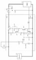
- FIG. 6 is a circuit diagram showing an example of a configuration in which the computer can turn off the latch switch to cut off the battery power.
- MPU IC2
- MPU is a microcomputer. As shown in FIG. 6, the power from the battery BT1 to the MPU is turned on and off by the power MOSFET of Q1, and is supplied via the power supply IC (IC1).
- the latch switch shown in FIG. 6 when pulsed external noise is momentarily superimposed on the path from the momentary switch SW30 to the base of Q32, Q1 is turned on due to the influence, and the user does not intend.
- the MPU starts processing.
- the momentary switch SW30 is merely used to turn on the latch switch and is not directly related to the processing of the MPU.
- the present invention has been made in consideration of the above circumstances, and in a battery-driven electronic device in which power supply to an on-board computer is turned on / off by a latch switch, the latch switch malfunctions with a simple circuit configuration. It is possible to provide a technique that can prevent the occurrence of the occurrence of a malfunction and can also serve as an operation input means to the computer.
- the present invention includes a battery having a battery terminal, a computer that receives power supply from the battery, a self-holding type latch switch that is connected between the battery and the computer and that turns on and off power supply to the computer.
- a momentary switch that guides the voltage of the battery terminal to the trigger input of the latch switch when it is turned on and latches the latch switch in an on state; and a battery monitor that converts the voltage of the battery terminal into a battery monitor voltage that can be read by the computer
- the latch release circuit is operated when a predetermined range is exceeded.
- the computer when the computer starts executing the process, if the difference between the switch monitor voltage and the battery monitor voltage exceeds the range corresponding to the ON state of the momentary switch, the computer releases the latch switch by operating the latch release circuit. Since the switch is turned off, malfunction of the latch switch can be prevented with a simple circuit configuration, and the computer can monitor a momentary switch that gives an on-trigger to the latch switch.
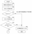
- 4 is a flowchart illustrating processing executed by an MPU in the embodiment of the present invention.
- (Initial stage of processing) 4 is a flowchart illustrating processing executed by an MPU in the embodiment of the present invention.
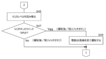
- (During operation and standby 1) 4 is a flowchart illustrating processing executed by an MPU in the embodiment of the present invention.
- (During operation and standby 2) It is a circuit diagram which shows the structural example of the conventional latch switch.
- FIG. 1 is an explanatory diagram showing a configuration example of a battery-driven vacuum cleaner 11 which is an aspect of the electronic apparatus of the present invention.
- the cleaner 11 is a canister-type cleaner, and is roughly divided into a cleaner body, a suction hose 17, and a battery 13.
- the battery 13 and the suction hose 17 can be attached to and detached from the cleaner body, and are electrically connected via a connector.
- the battery 13 has battery terminals 13a and 13b, and is connected to the cleaner body via the battery terminals 13a and 13b.
- the battery 13 is assumed to be a secondary battery such as a lithium ion battery, but is not limited thereto.
- the vacuum cleaner main body may be housed inside the vacuum cleaner main body and covered with a lid, or may be exposed to the outside of the vacuum cleaner main body.
- the control circuit 15 is disposed in the cleaner body, and the driving strength / weakness switch 30 is a momentary switch and is disposed in the suction hose 17.
- FIG. 1 is merely an example.
- the driving strength / weakness switch 30 may be provided in the cleaner body instead of the suction hose 17.
- the cleaner 11 is not limited to the canister type, and may be, for example, a self-propelled cleaner or a handy type cleaner that does not have the suction hose 17.
- the electronic device of the present invention is not limited to a vacuum cleaner.
- the control circuit 15 includes a latch switch 31, a power supply IC 21, an MPU 23, and a motor drive circuit 25.
- the motor drive circuit 25 drives the motor of the electric blower 29 arranged in the cleaner body.
- the configuration 31 of the latch switch is the same as the latch switch SW31 shown in FIG.
- the power supply IC 21 is the same as the power supply IC (IC1) of FIG.
- the MPU 23 corresponds to the computer of the present invention.
- the MPU 23 controls the motor drive circuit 25.
- the resistors R11 and R12 in the control circuit 15 constitute a voltage dividing circuit, and the voltage dividing circuit corresponds to the battery monitor circuit of the present invention.
- One end of the resistor R11 is connected to the battery terminal 13a via the latch switch 31.
- the voltage of the battery terminal 13a is divided by the resistors R11 and R12 to generate the signal Vin, which is input to the MPU 23 and internally A / D converted. That is, the MPU 23 reads the voltage level obtained by dividing the voltage of the battery terminal 13a.
- the power supply IC 21 is a step-down stabilized power supply circuit, the MPU 23 operates with a power supply voltage lower than the output voltage of the battery 13.
- the voltage dividing circuit of the resistors R11 and R12 converts the voltage of the battery terminal 13a into a voltage Vin in a range that the MPU 23 can correctly read.
- the resistors R13 and R14 in the control circuit 15 constitute a voltage dividing circuit, and the voltage dividing circuit corresponds to the switch monitor circuit of the present invention.
- One end of the resistor R13 (location indicated by a latch-on signal in FIG. 1) is connected to the battery terminal 13a via the driving strength / weakness switch 30.
- the driving strength / weakness switch 30 corresponds to the momentary switch of the present invention.
- the potential of the latch-on signal is equal to the output voltage of the battery terminal 13a when the driving strength / weak switch 30 is on, but becomes the ground potential when the driving strength / weak switch 30 is off. This latch-on signal is connected to the latch switch 31.
- the latch switch 31 When the driving strength / weak switch 30 is turned on for a moment, the latch switch 31 is in a latched state and is kept on, and power is supplied to the MPU 23. Further, the latch-on signal is divided by the resistors R13 and R14 to generate the voltage signal V1, which is input to the MPU 23 and internally A / D converted. The voltage dividing circuit of the resistors R13 and R14 converts the voltage of the latch-on signal into a voltage signal V1 in a range that the MPU 23 can correctly read.
- the resistors R16 and R17 in the control circuit 15 constitute different voltage dividing circuits.
- One end of the resistor R16 is connected to the battery terminal 13a via the off switch 32.
- the off switch 32 When the off switch 32 is on, the voltage of the battery terminal 13a is divided by the resistors R16 and R17 to generate the voltage signal V2, which is input to the MPU 23 and internally A / D converted.
- the off switch 32 When the off switch 32 is off, it becomes a ground potential.
- the MPU 23 monitors the state of the off switch 32 by reading the level of V2. When recognizing that the off switch 32 is pressed during operation, the MPU 23 controls the motor drive circuit 25 to stop the operation of the electric blower 29.
- One of the output ports of the MPU 23 is connected to a latch switch 31 (indicated by a latch release signal in FIG. 1).
- the latch state of the latch switch 31 is released. This portion corresponds to the latch release circuit of the present invention.
- the driving strength / weak switch 30 is pressed when the cleaner 11 is in the power-off state
- the latch switch 31 is turned on and power is supplied to the MPU 23.
- the MPU 23 starts executing (processing) a predetermined control program.
- the MPU 23 reads the voltage levels of the input signals Vin and V1.
- the operation of the driving strength / weakness switch 30 is performed by a person. Even if it is a momentary on as a sense of operation performed by a person, a sufficiently long period of time elapses compared to the following circuit operation. In other words, when the driving strength / weak switch 30 is pressed, the latch switch 31 is turned on, and the MPU 23 starts processing to read the voltage levels of Vin and V1. Therefore, when the MPU 23 reads the voltage levels of Vin and V1, it is assumed that the driving strength / weak switch 30 is still pressed and the on state continues. In addition, when it is assumed that time is required from the turning on of the driving strength / weak switch 30 to the reading of the voltage levels of Vin and V1, a delay circuit 27 may be inserted into V1.
- a simple delay circuit can consist of resistors and capacitors. Since the delay circuit 27 is not an essential component, it is indicated by a chain line. Thus, by devising the circuit configuration, when the MPU 23 reads the voltage levels of Vin and V1, it is assumed that the driving strength / weak switch 30 is kept on.
- the MPU 23 reads the voltage levels of Vin and V1 and makes the following determination.
- the driving strength / weak switch 30 is on, the latch-on signal is equal to the voltage at the battery terminal 13a. Therefore, the voltage levels of V1 and Vin must be equal. If the voltage levels of V1 and Vin are different, it is considered that the disturbance switch is superimposed on the latch-on signal and the latch switch 31 is turned on. Therefore, when it is determined that the voltage levels of V1 and Vin are different, the MPU 23 releases the latch state of the latch switch 31 by setting the latch release signal high. Then, the power supply to the MPU 23 is interrupted and the process stops.
- the MPU 23 can recognize the on / off state of the driving strength / weakness switch 30 by sequentially monitoring V1 during driving. In this embodiment, when the driving strength / weak switch 30 is turned on during driving, the MPU 23 recognizes this and controls the motor drive circuit 25 to change the rotational speed of the electric blower 29 from low speed to high speed or vice versa. Switch.
- the MPU 23 When determining the ON / OFF state of the driving strength / weak switch 30 during driving, the MPU 23 makes a determination by comparing Vin and V1 as in the initial stage of the process start. And if both are equal, it will recognize that the driving strong / weak switch 30 is an ON state.
- the driving strength / weak switch 30 is within a predetermined level range (ON window), it is determined that the switch is ON. If it is within a predetermined level range (off window), it is determined to be off.
- the voltage of the battery terminal 13a decreases with use. Along with this, the Vin level also decreases.
- the V1 level when the driving strength / weak switch 30 is on also decreases.
- the MPU 23 reads the voltage levels of Vin and V1, and compares the voltage level of V1 with the level of Vin to determine whether the driving strength / weak switch 30 is in the on window or in the off window.
- the MPU 23 recognizes that noise is superimposed on the latch-on signal. At the initial stage of processing, if it is recognized as noise, a latch release signal is output. During driving, no operation is performed and the driving strength / weak switch 30 is ignored because it is off.
- the driving strength / weak switch 30 has a function as hardware for turning on the latch switch 31 and a function as means for giving an instruction for software processing by causing the MPU 23 to monitor the on / off state.
- one switch can have two functions by the configuration shown in this embodiment.
- FIG. 2 is an explanatory view showing a configuration example different from the cleaner of FIG. Components corresponding to those in FIG. 1 are denoted by the same reference numerals. Differences from FIG. 1 will be described.
- a resistance R15 of the suction hose 17 is added.
- the resistors R15, R16, R17 and the off switch 32 correspond to the second voltage dividing circuit of the present invention.
- the resistor R15 corresponds to a first pull-up resistor
- the resistor R16 corresponds to a second pull-up resistor
- the resistor R17 corresponds to a ground resistor
- the off switch 32 corresponds to a second momentary switch.
- One end of the resistor R15 and one end of the off switch 32 are both connected to the battery terminal 13a via a connector 17a that connects the suction hose 17 and the cleaner body.
- a voltage signal V2 at a connection point between the resistors R16 and R17 is input to the MPU 23.
- a voltage signal V2 obtained by dividing the voltage of the battery terminal 13a by the resistors R15 to R17 is input to the MPU 23 and A / D converted.
- the second voltage dividing circuit of the resistors R15 to R17 converts the terminal voltage of the battery 13a into a voltage signal V1 in a range that the MPU 23 can correctly read.
- the voltage division ratio changes depending on whether the off switch 32 is on or off, and the voltage level of V2 changes accordingly.
- the second voltage dividing circuit performs two detections, that is, ON / OFF of the off switch 32 and detection of the attachment state of the suction hose 17.
- the suction hose 17 is attached, the potential of V2 becomes a level obtained by dividing the voltage of the battery terminal 13a by the resistors R15 and R17.
- V2 becomes the ground potential.
- the off switch 32 is turned on, the potential of V2 becomes a level obtained by dividing the voltage of the battery terminal 13a by the parallel resistance of the resistors R15 and R16 and R17.
- V2 takes three levels depending on the combination of the insertion / extraction of the suction hose 17 and the on / off of the switch 32.
- the MPU 23 monitors the voltage level of V2 to recognize the disconnection of the suction hose 17 and the operation of the off switch.
- the MPU 23 sequentially monitors the voltage level of V2 during operation.
- the MPU 23 makes a determination by comparing Vin and V2 as in the monitor of V1 in the first embodiment. Specifically, the voltage level of V2 is determined based on the voltage level of Vin. In reality, there are variations in circuit element characteristics and measurement errors, so that (1) the suction hose 17 is disconnected, (2) the suction hose 17 is attached and the switch 32 is off, and (3) suction.
- Three windows corresponding to the respective states in which the hose 17 is attached and the switch 32 is turned on are determined in advance. If the voltage level of V2 is within the range of any window, the state is recognized, but if V2 does not fit in any window, it is ignored as noise.
- the MPU 23 determines that it has received an instruction to stop operation, stops the electric blower (not shown), and sets the latch release signal to high. As a result, the latch switch 31 is turned off, and the power supply to the MPU 23 is interrupted. Note that the MPU does not have to actively stop the electric blower. When the latch switch 31 is turned off, the power supply to the electric blower is cut off and the electric blower stops.
- FIG. 3 is an initial stage in which power is supplied to the MPU 23 and execution of the process is started
- FIGS. 4 and 5 are processes after the initial stage of FIG. Each of them shows processing deeply related to the present invention, and other processing is omitted.
- the MPU 23 which has started the processing with the latch switch 31 turned on and supplied with power from the battery 13 first performs initialization necessary for operating the control circuit such as initial setting of the memory and input / output ports. Processing is executed (step S11). Thereafter, the MPU 23 reads the level of Vin corresponding to the voltage of the battery terminal 13a (step S13), and determines whether or not the lower limit voltage at which the MPU 23 can stably operate is equal to or higher than a predetermined threshold Vmin (step S15). ). If the level of Vin is less than Vmin (No in step S15), it is determined that the operation is impossible, the latch release signal is set high (step S23), and the process is terminated. As a result, the latch switch 31 is turned off, the power supply to the MPU 23 is cut off, and the operation is stopped.
- Step S15 the MPU 23 reads the V1 level indicating the state of the driving strength / weak switch 30 (Step S17). Then, it is checked whether or not the level of V1 is equal to the level of Vin (step S19). That is, it is checked whether or not the driving strength / weak switch 30 is at a level in the window to be recognized as being on. If the level of V1 is not within the ON window (No in step S19), it is determined that the latch switch 31 is turned on because disturbance noise is superimposed on the latch-on signal, and the routine proceeds to step S21. Set to high to end processing. As a result, the latch switch 31 is turned off and the power supply to the MPU 23 is interrupted.
- step S19 determines that the V1 level is within the ON window (Yes in step S19)
- the MPU 23 reads the level of Vin corresponding to the voltage of the battery terminal 13a (step S31) and determines whether or not it is equal to or higher than the threshold value Vmin (step S33). If the level of Vin is less than Vmin (No in step S33), it is determined that the operation is impossible, the latch release signal is set high (step S34), and the process is terminated. As a result, the latch switch 31 is turned off and the power supply to the MPU 23 is interrupted. On the other hand, if the Vin level is equal to or higher than Vmin in Step S33 (Yes in Step S33), the MPU 23 then reads the V1 level indicating the state of the driving strength / weak switch 30 (Step S35). Then, it is checked whether or not the level of V1 is equal to the level of Vin, that is, whether or not the level is within the window in which it should be recognized that the driving strength / weak switch 30 is on (step S37).
- step S53 If V1 is not in the ON window (No in step S37), it is determined that the driving strength / weakness switch 30 has not been operated, and the process proceeds to step S53 without switching the strength of the electric blower.
- the MPU 23 determines whether or not any of the driving strength / weak switch 30 and the off switch 32 has been operated for 30 seconds. The period of 30 seconds is just an example. If it is determined that any key has been operated within 30 seconds, the routine proceeds to step S31 described above and repeats the Vin level determination. On the other hand, if it is determined that no key has been operated for 30 seconds (Yes in step S53), the latch release signal is set high and the process is terminated (step S55). As a result, the latch switch 31 is turned off and the power supply to the MPU 23 is interrupted.
- step S37 If it is determined in step S37 that the V1 level is within the ON window (Yes in step S37), it is determined that the driving strength / weak switch 30 is turned on by the user's operation, and the electric blower 29 is set to “strong”.
- the motor drive circuit 25 is controlled to rotate (step S39). If the determination in step S37 is reached after the determination in step S19 in FIG. 3, the level of V1 is double-checked, but a duplicate check may be avoided. In that case, what is necessary is just to determine to advance a routine to step S39, when determination of the said step S19 is Yes.
- the MPU 23 reads the level V2 indicating the state of the off switch 32 (step S41). Then, it is checked whether or not the level of V2 is equal to the level of Vin, that is, whether or not it is a level within a window that should be recognized that the off switch 32 is on (step S43). If the V2 level is within the ON window (Yes in step S43), it is determined that the switch 32 is turned on by the user's operation, and the operation of the electric blower is stopped (step S51). Thereafter, the routine proceeds to step S31 described above, and repeats the determination of the Vin level and the key input. As described above, when neither the driving strength / weak switch 30 nor the off switch 32 is operated for 30 seconds continuously, the latch release signal is set high and the process is terminated (step S55).
- Step S43 If it is determined in S43 that the level of V2 is not within the ON window (No in Step S43), the routine proceeds to Step S45 in FIG. 5 and reads the level of V1 indicating the state of the driving strength / weak switch 30 ( Step S45). Then, it is checked whether or not the level of V1 is equal to the level of Vin, that is, whether or not the level is within the window in which the driving strength / weak switch 30 should be recognized as being on (step S47).
- step S47 If V1 is not within the ON window (No in step S47), it is determined that the driving strength / weakness switch 30 has not been operated, and the process proceeds to step S31 without switching the strength of the electric blower. Repeat the key input determination. As described above, when neither the driving strength / weak switch 30 nor the off switch 32 is operated for 30 seconds continuously, the latch release signal is set high and the process is terminated (step S49). If it is determined in step S47 that the V1 level is within the ON window (Yes in step S47), it is determined that the driving strength / weak switch 30 is turned on by the user's operation, and the electric blower 29 is set to “weak”. The motor drive circuit 25 is controlled to rotate (step S49). Thereafter, the routine proceeds to step S31 described above, and repeats the determination of the Vin level and the key input.
- a voltage stabilization circuit similar to the power supply IC 21 may be used instead of the voltage dividing circuit of the resistors R13 and R14, and the output voltage may be read by the MPU 23 as V1.
- the circuit configuration is more complicated than that of the voltage dividing circuit, which is thought to lead to an increase in cost.
- Embodiment 4 Further, it has been described that it is preferable to make the voltage dividing ratio of the resistors R11 and R12 equal to the voltage dividing ratio of the resistors R13 and R14. However, it is not essential to equalize the partial pressure ratio between the two.
- the resistor R16 may be on the suction hose 17 side instead of the cleaner body.
- a battery-driven electronic device includes a battery having a battery terminal, a computer that receives power supply from the battery, and is connected between the battery and the computer to turn on power supply to the computer and A self-holding latch switch that turns off, a momentary switch that guides the voltage of the battery terminal to the trigger input of the latch switch when it is turned on, and latches the latch switch in an on state;
- a battery monitor circuit for converting to a battery monitor voltage, a switch monitor circuit for converting a voltage at a battery terminal via the momentary switch to a switch monitor voltage readable by the computer, and response to an output from the computer
- the latch release circuit for turning off the latch switch, and the computer compares the switch monitor voltage with the battery monitor voltage when the processing is started upon receiving power supply, and there is a difference in voltage.
- the latch release circuit is activated when a predetermined range is exceeded corresponding to the ON state of the momentary switch.
- the computer may recognize the on / off state of the momentary switch by sequentially comparing the switch monitor voltage and the battery monitor voltage during execution of the process. In this way, even if the voltage at the battery terminal decreases with use, the switch monitor voltage and the battery monitor voltage are sequentially compared so that the on / off state of the momentary switch can be correctly recognized.
- the battery monitoring circuit is a voltage dividing circuit that divides the voltage of the battery terminal by a predetermined voltage dividing ratio and converts the divided voltage into the battery monitoring voltage, and the switch monitoring circuit passes through the momentary switch.
- a voltage dividing circuit that divides the voltage of the battery terminal at the same voltage dividing ratio as the battery monitoring circuit and converts the divided voltage into the switch monitoring voltage may be used. In this way, the battery monitor voltage indicating the voltage of the battery terminal and the switch monitor voltage indicating the on / off state of the momentary switch can be converted into a computer-readable voltage by a simple voltage dividing circuit, and the two voltages are equal. It can be recognized that the momentary switch is on.
- a second voltage dividing circuit including a ground resistor, first and second pull-up resistors, and a second momentary switch, wherein the second momentary switch and the second pull-up resistor are connected in series and connected to the second pull-up resistor;
- the first pull-up resistor is connected in parallel with the second pull-up route, one end of the contact resistor is grounded, and the other end is one end side of the first pull-up resistor and the second pull-up resistor.
- a second switch monitor voltage input to the computer, the second pull-up path and the first pull-up resistor are pulled up to the battery terminal, and the first pull-up resistor and
- the second momentary switch is disposed in a unit that can be attached to and detached from the device body, and the ground resistance and the computer are Disposed vessel body, the computer may detect the detachment and the second momentary switch on and off of the unit reads the second switch monitor voltage. By doing this, it is possible to recognize both the attachment / detachment of the unit and the on / off state of the second momentary switch by reading the level of the second switch monitor voltage.
- the battery-driven electronic device may be a battery-driven vacuum cleaner, and the unit may be a suction hose.
- the attachment / detachment of the suction hose and the on / off state of the switch arranged in the suction hose can be recognized.
- Preferred embodiments of the present invention include combinations of any of the plurality of embodiments described above.
- the present invention should include the meaning equivalent to the scope of the claims and all modifications within the scope.
Landscapes
- Engineering & Computer Science (AREA)
- Theoretical Computer Science (AREA)
- Power Engineering (AREA)
- Physics & Mathematics (AREA)
- General Engineering & Computer Science (AREA)
- General Physics & Mathematics (AREA)
- Charge And Discharge Circuits For Batteries Or The Like (AREA)
- Direct Current Feeding And Distribution (AREA)
- Control Of Electric Motors In General (AREA)
Abstract
バッテリー端子を有するバッテリーと、前記バッテリーから電力供給を受けるコンピュータと、前記バッテリーと前記コンピュータとの間に接続され前記コンピュータへの電力供給をオンおよびオフする自己保持型のラッチスイッチと、オンにより前記バッテリー端子の電圧を前記ラッチスイッチのトリガ入力に導き前記ラッチスイッチをオン状態にラッチするモーメンタリースイッチと、前記バッテリー端子の電圧を前記コンピュータが読み取り可能な電池モニタ電圧に変換する電池モニタ回路と、前記モーメンタリースイッチを介したバッテリー端子の電圧を前記コンピュータが読み取り可能なスイッチモニタ電圧に変換するスイッチモニタ回路と、前記コンピュータからの出力に応答して前記ラッチスイッチをオフさせるラッチ解除回路とを備え、前記コンピュータは、電力供給を受けて処理の実行を開始したときに前記スイッチモニタ電圧と前記電池モニタ電圧とを比較し、電圧の差異が前記モーメンタリースイッチのオン状態に対応して予め定められた範囲を超えるときは前記ラッチ解除回路を作動させるバッテリー駆動式電子機器。
Description
この発明は、バッテリー駆動式電子機器に関し、より詳細にはバッテリーから電力供給を受けて動作するコンピュータとその電力供給をオンおよびオフするラッチスイッチとを備えた電子機器に関する。
バッテリーを電源とし、マイクロコンピュータ等のコンピュータを搭載した種々の電子機器が知られている。近年は電池の進歩により小型軽量で大容量のものが安価で入手できるようになっている。それに伴い、比較的消費電力の小さい携帯電話等の情報処理機器に限らず、モータを搭載した掃除機などにもバッテリー駆動式のものが増えつつある。しかし、大小の差はあってもバッテリーの容量に限りがある以上、消費電力の低減は常に課題となる。
コンピュータを搭載したバッテリー駆動式の電子機器では、コンピュータが動作(処理実行)するためにバッテリーから電力を供給する必要がある。なお、バッテリーは使用に伴ってその端子電圧が降下するところ、コンピュータを安定して動作させるためにバッテリーからの電源は電源ICで電圧を安定化したうえでコンピュータに供給される。
コンピュータを搭載したバッテリー駆動式の電子機器では、コンピュータが動作(処理実行)するためにバッテリーから電力を供給する必要がある。なお、バッテリーは使用に伴ってその端子電圧が降下するところ、コンピュータを安定して動作させるためにバッテリーからの電源は電源ICで電圧を安定化したうえでコンピュータに供給される。
しかし、電子機器を動作させない期間、コンピュータに電力を供給し続けるのは待機電力の消費低減の観点から好ましくない。この無駄に消費される電力を削減することに着目し、コンピュータ等の電子回路が動作していないときに電力源と電子回路との間を完全に遮断するためにスイッチング手段を設け、さらに環境エネルギーを電気エネルギーに変換する発電源と、前記発電源の電力で駆動されてラッチ式または切り替え式のスイッチング手段を制御するスイッチ制御回路とを備えた電子装置が提案されている(例えば、特許文献1参照)。
また、前記発電源および前記スイッチ制御回路に代えて、前記コンピュータが作業を終えたときに自ら前記スイッチング手段をオフできるように前記スイッチング手段にラッチスイッチを適用し、待機状態に入るとコンピュータが前記ラッチスイッチをオフにして前記コンピュータへのバッテリーの電力を遮断するように構成したものが知られている。
図6は、コンピュータが自らラッチスイッチをオフしてバッテリーの電力を遮断し得るようにした構成の一例を示す回路図である。図6で、鎖線で囲んだ部分がラッチスイッチSW31である。MPU(IC2)は、マイクロコンピュータである。図6に示すように、バッテリーBT1からMPUへの電源は、Q1のパワーMOSFETでオンおよびオフされ、電源IC(IC1)を経て供給される。トランジスタQ31またはQ32をオンにしてQ1のゲート端子の電位を下げればQ1はオンになるが、モーメンタリースイッチSW30がオフの初期状態ではトランジスタQ32がオフであり、従ってトランジスタQ31のベースに電流は流れずQ31はオフである。トランジスタQ31およびQ32が共にオフであれば、Q1のゲート端子は電位が下がらずQ1はオフしている。
また、前記発電源および前記スイッチ制御回路に代えて、前記コンピュータが作業を終えたときに自ら前記スイッチング手段をオフできるように前記スイッチング手段にラッチスイッチを適用し、待機状態に入るとコンピュータが前記ラッチスイッチをオフにして前記コンピュータへのバッテリーの電力を遮断するように構成したものが知られている。
図6は、コンピュータが自らラッチスイッチをオフしてバッテリーの電力を遮断し得るようにした構成の一例を示す回路図である。図6で、鎖線で囲んだ部分がラッチスイッチSW31である。MPU(IC2)は、マイクロコンピュータである。図6に示すように、バッテリーBT1からMPUへの電源は、Q1のパワーMOSFETでオンおよびオフされ、電源IC(IC1)を経て供給される。トランジスタQ31またはQ32をオンにしてQ1のゲート端子の電位を下げればQ1はオンになるが、モーメンタリースイッチSW30がオフの初期状態ではトランジスタQ32がオフであり、従ってトランジスタQ31のベースに電流は流れずQ31はオフである。トランジスタQ31およびQ32が共にオフであれば、Q1のゲート端子は電位が下がらずQ1はオフしている。
モーメンタリースイッチSW30がオンすると、トランジスタQ32のベースに電圧がかかり、Q32がオンする。すると、Q31のベースとエミッタの間の抵抗R32に電流が流れ、Q31がオンする。Q31がオンすると、そのコレクタから抵抗R34を経てQ32のベースに電流が流れるので、モーメンタリースイッチSW30がオフになってもQ32はオンの状態を維持する。よって、Q31もオンの状態を維持する。Q31およびQ32のオン状態が続くと、Q1のゲート端子の電位が下がりQ1のオンが続く。これがラッチ状態である。
MPUが抵抗R36の一端に接続された出力ポートをハイにすると、Q33がオンになりQ32のベースがQ33を介して接地される。よって、Q32がオフ状態になり、Q31およびQ1がオフ状態になる。このようにMPUからの出力によって、ラッチ状態が解除される。
MPUが抵抗R36の一端に接続された出力ポートをハイにすると、Q33がオンになりQ32のベースがQ33を介して接地される。よって、Q32がオフ状態になり、Q31およびQ1がオフ状態になる。このようにMPUからの出力によって、ラッチ状態が解除される。
図6に示すラッチスイッチで、モーメンタリースイッチSW30からQ32のベースに至る経路にパルス状の外部ノイズが一瞬重畳されるとその影響でQ1がオンのラッチ状態になってしまい、ユーザが意図しないときにMPUが処理を開始してしまう。
また、図6の回路で機器を制御するMPUがあるにも関わらずモーメンタリースイッチSW30は、単にラッチスイッチをオンするために用いられているに過ぎずMPUの処理とは直接関係しない。
この発明は、以上のような事情を考慮してなされたものであって、搭載されたコンピュータへの電力供給をラッチスイッチでオンオフするバッテリー駆動式の電子機器において単純な回路構成でラッチスイッチの誤動作が防止できかつ前記ラッチスイッチにオンのトリガを与えるスイッチを前記コンピュータへの操作入力手段として兼用できる手法を提供するものである。
また、図6の回路で機器を制御するMPUがあるにも関わらずモーメンタリースイッチSW30は、単にラッチスイッチをオンするために用いられているに過ぎずMPUの処理とは直接関係しない。
この発明は、以上のような事情を考慮してなされたものであって、搭載されたコンピュータへの電力供給をラッチスイッチでオンオフするバッテリー駆動式の電子機器において単純な回路構成でラッチスイッチの誤動作が防止できかつ前記ラッチスイッチにオンのトリガを与えるスイッチを前記コンピュータへの操作入力手段として兼用できる手法を提供するものである。
この発明は、バッテリー端子を有するバッテリーと、前記バッテリーから電力供給を受けるコンピュータと、前記バッテリーと前記コンピュータとの間に接続され前記コンピュータへの電力供給をオンおよびオフする自己保持型のラッチスイッチと、オンにより前記バッテリー端子の電圧を前記ラッチスイッチのトリガ入力に導き前記ラッチスイッチをオン状態にラッチするモーメンタリースイッチと、前記バッテリー端子の電圧を前記コンピュータが読み取り可能な電池モニタ電圧に変換する電池モニタ回路と、前記モーメンタリースイッチを介したバッテリー端子の電圧を前記コンピュータが読み取り可能なスイッチモニタ電圧に変換するスイッチモニタ回路と、前記コンピュータからの出力に応答して前記ラッチスイッチをオフさせるラッチ解除回路とを備え、前記コンピュータは、電力供給を受けて処理の実行を開始したときに前記スイッチモニタ電圧と前記電池モニタ電圧とを比較し、電圧の差異が前記モーメンタリースイッチのオン状態に対応して予め定められた範囲を超えるときは前記ラッチ解除回路を作動させることを特徴とするバッテリー駆動式電子機器を提供する。
この発明において、コンピュータは処理の実行を開始したときにスイッチモニタ電圧と電池モニタ電圧との差異が前記モーメンタリースイッチのオン状態に対応する範囲を超えるときはラッチ解除回路を作動させて前記ラッチスイッチをオフするので、単純な回路構成でラッチスイッチの誤動作が防止できかつ前記ラッチスイッチにオンのトリガを与えるモーメンタリースイッチを前記コンピュータがモニタすることで操作入力手段として兼用できる。
以下、図面を用いてこの発明をさらに詳述する。なお、以下の説明は、すべての点で例示であって、この発明を限定するものと解されるべきではない。
(実施の形態1)
図1は、この発明の電子機器の一態様であるバッテリー駆動式の掃除機11の構成例を示す説明図である。分かり易くするためにこの発明と関連の深い部分のみを示しており、いくつかの周知の要素は省略している。掃除機11は、この実施形態においてはキャニスター型の掃除機であり、掃除機本体、吸引ホース17およびバッテリー13に大別される。バッテリー13および吸引ホース17は、掃除機本体に着脱可能であり、電気的にはコネクタを介して接続される。なお、バッテリー13は、バッテリー端子13aおよび13bを有し、バッテリー端子13aおよび13bを介して掃除機本体に接続される。バッテリー13は、リチウムイオン電池等の二次電池を想定しているが、それに限定されるものでない。掃除機本体に装着された状態で掃除機本体の内部に収容され蓋で覆われていてもよいし、掃除機本体の外側に露出していてもよい。
図1は、この発明の電子機器の一態様であるバッテリー駆動式の掃除機11の構成例を示す説明図である。分かり易くするためにこの発明と関連の深い部分のみを示しており、いくつかの周知の要素は省略している。掃除機11は、この実施形態においてはキャニスター型の掃除機であり、掃除機本体、吸引ホース17およびバッテリー13に大別される。バッテリー13および吸引ホース17は、掃除機本体に着脱可能であり、電気的にはコネクタを介して接続される。なお、バッテリー13は、バッテリー端子13aおよび13bを有し、バッテリー端子13aおよび13bを介して掃除機本体に接続される。バッテリー13は、リチウムイオン電池等の二次電池を想定しているが、それに限定されるものでない。掃除機本体に装着された状態で掃除機本体の内部に収容され蓋で覆われていてもよいし、掃除機本体の外側に露出していてもよい。
図1で、制御回路15は、掃除機本体に配置され、運転強/弱スイッチ30は、モーメンタリースイッチであって吸引ホース17に配置されている。ただし、図1は単なる一例に過ぎず、例えば運転強/弱スイッチ30は、吸引ホース17ではなく掃除機本体にあってもよい。さらに、掃除機11はキャニスター型に限定されず、例えば吸引ホース17を持たない自走式掃除機やハンディータイプの掃除機であってもよい。さらにいえば、この発明の電子機器は掃除機に限定されるものでない。
図1の説明に戻る。制御回路15は、ラッチスイッチ31、電源IC21、MPU23およびモータ駆動回路25を備える。モータ駆動回路25は、掃除機本体に配置された電動送風機29のモータを駆動する。ラッチスイッチの構成31は、図6に示すラッチスイッチSW31と同様である。電源IC21は、図6の電源IC(IC1)と同様である。MPU23はこの発明のコンピュータに該当する。MPU23は、モータ駆動回路25を制御する。
制御回路15内にある抵抗R11および抵抗R12は分圧回路を構成し、その分圧回路はこの発明の電池モニタ回路に該当する。抵抗R11の一端は、ラッチスイッチ31を介してバッテリー端子13aに接続されている。バッテリー端子13aの電圧が抵抗R11とR12により分圧されて信号Vinが生成され、MPU23に入力されて内部でA/D変換される。即ち、MPU23はバッテリー端子13aの電圧が分圧された電圧レベルを読み取る。電源IC21が降圧型安定化電源回路の場合、MPU23はバッテリー13の出力電圧よりも低い電源電圧で動作する。よって、バッテリー端子13aの電圧を分圧せずに入力するとA/D変換の上限を超えてしまい、バッテリー13の出力電圧を正しく読取ることができない。抵抗R11およびR12の分圧回路は、バッテリー端子13aの電圧をMPU23が正しく読み取れる範囲の電圧Vinに変換する。
また、制御回路15内にある抵抗R13および抵抗R14は分圧回路を構成し、その分圧回路はこの発明のスイッチモニタ回路に該当する。抵抗R13の一端(図1にラッチオン信号で示す箇所)は、運転強/弱スイッチ30を介してバッテリー端子13aに接続されている。運転強/弱スイッチ30はこの発明のモーメンタリースイッチに該当する。ラッチオン信号の電位は運転強/弱スイッチ30がオンのときはバッテリー端子13aの出力電圧に等しいが、運転強/弱スイッチ30がオフのときはグランド電位になる。このラッチオン信号はラッチスイッチ31に接続されており、運転強/弱スイッチ30が一瞬オンするとラッチスイッチ31がラッチ状態になってオンを維持し、MPU23に電力が供給される。
また、抵抗R13とR14によりラッチオン信号が分圧されて電圧信号V1が生成され、MPU23に入力されて内部でA/D変換される。抵抗R13およびR14の分圧回路は、ラッチオン信号の電圧をMPU23が正しく読み取れる範囲の電圧信号V1に変換する。
また、抵抗R13とR14によりラッチオン信号が分圧されて電圧信号V1が生成され、MPU23に入力されて内部でA/D変換される。抵抗R13およびR14の分圧回路は、ラッチオン信号の電圧をMPU23が正しく読み取れる範囲の電圧信号V1に変換する。
制御回路15内にある抵抗R16および抵抗R17は異なる分圧回路を構成する。抵抗R16の一端は、切スイッチ32を介してバッテリー端子13aに接続されている。切スイッチ32がオンのとき、バッテリー端子13aの電圧が抵抗R16とR17により分圧されて電圧信号V2が生成され、MPU23に入力されて内部でA/D変換される。切スイッチ32がオフのときはグランド電位になる。MPU23は、V2のレベルを読み取って切スイッチ32の状態をモニタする。運転中に切スイッチ32が押されたことを認識すると、MPU23はモータ駆動回路25を制御して電動送風機29の運転を停止させる。
MPU23の出力ポートの一つは、ラッチスイッチ31に接続されている(図1にラッチ解除信号で示す)。MPU23がその出力ポートをハイにすると、ラッチスイッチ31のラッチ状態が解除される。この部分は、この発明のラッチ解除回路に該当する。
この実施形態において、掃除機11が電源オフの状態にあるとき運転強/弱スイッチ30が押されると、ラッチスイッチ31がオンのラッチ状態になり、MPU23に電力が供給される。すると、MPU23は予め定められた制御プログラムの実行(処理)を開始する。処理の初期段階で、MPU23は、入力信号VinおよびV1の電圧レベルを読み取る。
この実施形態において、掃除機11が電源オフの状態にあるとき運転強/弱スイッチ30が押されると、ラッチスイッチ31がオンのラッチ状態になり、MPU23に電力が供給される。すると、MPU23は予め定められた制御プログラムの実行(処理)を開始する。処理の初期段階で、MPU23は、入力信号VinおよびV1の電圧レベルを読み取る。
抵抗R11とR12による分圧比と抵抗R13とR14による分圧比とを等しく設定することが好ましい。両者の分圧比を等しくすることで、VinとV1との電圧レベルの比較が容易になる。R11とR13の抵抗値を互いに等しくし、R12とR14の抵抗値を互いに等しくすれば容易に実現できる。
運転強/弱スイッチ30の操作は人が行う。人が行う操作の感覚として一瞬のオンであっても、以下の回路動作に比べると十分長い期間が経過する。即ち、運転強/弱スイッチ30が押されたら、ラッチスイッチ31がオンし、MPU23が処理を開始してVinおよびV1の電圧レベルを読み取る回路動作である。従って、MPU23がVinおよびV1の電圧レベルを読み取るときには、まだ運転強/弱スイッチ30が押されてオンが継続しているとの想定が成り立つ。
また、運転強/弱スイッチ30のオンからVinおよびV1の電圧レベルの読み取りまでに時間を要することが想定される場合、V1に遅延回路27を挿入してもよい。単純な遅延回路は抵抗とコンデンサで構成できる。遅延回路27は必須の構成要素でないため鎖線で示している。このように、回路構成を工夫することで、MPU23がVinおよびV1の電圧レベルを読み取るときに、運転強/弱スイッチ30のオンが継続しているとの想定が成り立つ。
また、運転強/弱スイッチ30のオンからVinおよびV1の電圧レベルの読み取りまでに時間を要することが想定される場合、V1に遅延回路27を挿入してもよい。単純な遅延回路は抵抗とコンデンサで構成できる。遅延回路27は必須の構成要素でないため鎖線で示している。このように、回路構成を工夫することで、MPU23がVinおよびV1の電圧レベルを読み取るときに、運転強/弱スイッチ30のオンが継続しているとの想定が成り立つ。
MPU23は、VinおよびV1の電圧レベルを読み取って以下の判断を行う。運転強/弱スイッチ30がオンのとき、ラッチオン信号はバッテリー端子13aの電圧に等しい。従って、V1とVinの電圧レベルは等しくなければならない。もし、V1とVinの電圧レベルが異なる場合は、ラッチオン信号に外乱ノイズが重畳されてラッチスイッチ31がオンしたものと考えられる。そこで、V1とVinの電圧レベルが異なると判断した場合、MPU23は、ラッチ解除信号をハイにしてラッチスイッチ31のラッチ状態を解除する。すると、MPU23への電力供給が遮断されて処理が停止する。このようにして、外乱ノイズの影響でユーザが意図しないときにラッチスイッチ31がオンしても、MPU23が処理を開始した初期段階で自らラッチスイッチ31を遮断する。よって、誤動作による電源オンを防止できると共に、バッテリー13の無駄な電力消費を抑制できる。
さらに、正常な電源オンによりラッチスイッチ31がラッチ状態になり掃除機11の運転が開始された場合、運転中に運転強/弱スイッチ30がオンされてもラッチスイッチ31の状態に影響はない。一方、MPU23は、運転中もV1を逐次モニタすることで、運転強/弱スイッチ30のオンおよびオフ状態を認識できる。この実施形態で、運転中に運転強/弱スイッチ30がオンされると、MPU23はそれを認識し、モータ駆動回路25を制御して電動送風機29の回転速度を低速から高速へあるいはその逆に切換える。運転中に運転強/弱スイッチ30のオンおよびオフの状態を判定する際、MPU23は、処理開始の初期段階と同様にVinとV1とを比較して判断を行う。そして、両者が等しければ運転強/弱スイッチ30がオン状態であると認識する。
現実には、回路素子の特性のバラツキや測定誤差があるので、運転強/弱スイッチ30が予め定められたレベルの範囲(オンのウインドウ)に入っていればオンであると判断し、別に予め定められたレベルの範囲(オフのウインドウ)に入っていればオフであると判断する。
バッテリー端子13aの電圧は使用に伴って低下する。それに伴ってVinのレベルも低下するが、同様に運転強/弱スイッチ30がオンのときのV1のレベルも低下する。
MPU23はVinとV1の電圧レベルを読み取り、V1の電圧レベルをVinのレベルと比較して運転強/弱スイッチ30がオンのウインドウに入っているか、あるいはオフのウインドウに入っているかを判断する。よって、バッテリー端子13aの電圧が使用に伴って変化しても、運転強/弱スイッチ30のオンおよびオフを正しく認識できる。
V1の電圧レベルがオン、オフ何れのウインドウにも収まっていなければ、MPU23はラッチオン信号にノイズが重畳されたと認識する。処理開始の初期段階ではノイズと認識するとラッチ解除信号を出力する。運転中は、操作が行われず運転強/弱スイッチ30はオフであるとして無視する。
バッテリー端子13aの電圧は使用に伴って低下する。それに伴ってVinのレベルも低下するが、同様に運転強/弱スイッチ30がオンのときのV1のレベルも低下する。
MPU23はVinとV1の電圧レベルを読み取り、V1の電圧レベルをVinのレベルと比較して運転強/弱スイッチ30がオンのウインドウに入っているか、あるいはオフのウインドウに入っているかを判断する。よって、バッテリー端子13aの電圧が使用に伴って変化しても、運転強/弱スイッチ30のオンおよびオフを正しく認識できる。
V1の電圧レベルがオン、オフ何れのウインドウにも収まっていなければ、MPU23はラッチオン信号にノイズが重畳されたと認識する。処理開始の初期段階ではノイズと認識するとラッチ解除信号を出力する。運転中は、操作が行われず運転強/弱スイッチ30はオフであるとして無視する。
以上のように、運転強/弱スイッチ30は、ラッチスイッチ31をオンさせるハードウェアとしての機能と、MPU23にオンおよびオフの状態をモニタさせてソフトウェア処理に対する指示を与える手段としての機能を兼ね備える。換言すれば、この実施形態に示す構成によって1つのスイッチに2つの機能を持たせることができる。
(実施の形態2)
図2は、図1の掃除機とは異なる構成例を示す説明図である。図1に対応するものには同じ符号を付している。図1と異なる点について説明する。
図2で付加されているのは、吸引ホース17の抵抗R15である。
抵抗R15、R16、R17および切スイッチ32は、この発明の第2分圧回路に該当する。抵抗R15は、第1プルアップ抵抗に、抵抗R16は第2プルアップ抵抗に、抵抗R17は接地抵抗に、切スイッチ32は第2モーメンタリースイッチにそれぞれ該当する。
図2は、図1の掃除機とは異なる構成例を示す説明図である。図1に対応するものには同じ符号を付している。図1と異なる点について説明する。
図2で付加されているのは、吸引ホース17の抵抗R15である。
抵抗R15、R16、R17および切スイッチ32は、この発明の第2分圧回路に該当する。抵抗R15は、第1プルアップ抵抗に、抵抗R16は第2プルアップ抵抗に、抵抗R17は接地抵抗に、切スイッチ32は第2モーメンタリースイッチにそれぞれ該当する。
抵抗R15の一端および切スイッチ32の一端いずれも、吸引ホース17と掃除機本体とを接続するコネクタ17aを介してバッテリー端子13aに接続されている。抵抗R16とR17の接続ポイントの電圧信号V2はMPU23に入力される。
バッテリー端子13aの電圧が抵抗R15~R17で分圧された電圧信号V2が、MPU23に入力されA/D変換される。抵抗R15~R17の第2分圧回路は、バッテリー13aの端子電圧をMPU23が正しく読み取れる範囲の電圧信号V1に変換する。切スイッチ32がオンの場合とオフの場合とで分圧比が変わり、それに応じてV2の電圧レベルが変わる。
バッテリー端子13aの電圧が抵抗R15~R17で分圧された電圧信号V2が、MPU23に入力されA/D変換される。抵抗R15~R17の第2分圧回路は、バッテリー13aの端子電圧をMPU23が正しく読み取れる範囲の電圧信号V1に変換する。切スイッチ32がオンの場合とオフの場合とで分圧比が変わり、それに応じてV2の電圧レベルが変わる。
第2分圧回路は、切スイッチ32のオンおよびオフと吸引ホース17の装着状態の検出の2つの検出を行う。
吸引ホース17が装着されているとV2の電位はバッテリー端子13aの電圧が抵抗R15とR17で分圧されたレベルになる。吸引ホース17が抜けると、V2は接地電位になる。さらに、切スイッチ32がオンすると、V2の電位はバッテリー端子13aの電圧が抵抗R15およびR16の並列抵抗とR17とで分圧されたレベルになる。
吸引ホース17が装着されているとV2の電位はバッテリー端子13aの電圧が抵抗R15とR17で分圧されたレベルになる。吸引ホース17が抜けると、V2は接地電位になる。さらに、切スイッチ32がオンすると、V2の電位はバッテリー端子13aの電圧が抵抗R15およびR16の並列抵抗とR17とで分圧されたレベルになる。
以上のように、吸引ホース17の挿抜と切スイッチ32のオンオフの組合せによりV2は3つのレベルをとる。MPU23は、V2の電圧レベルをモニタして吸引ホース17の抜けおよび切スイッチの操作を認識する。MPU23は、運転中にV2の電圧レベルを逐次モニタする。
MPU23は、実施の形態1におけるV1のモニタと同様にVinとV2とを比較して判断を行う。詳細には、Vinの電圧レベルを基準にV2の電圧レベルを判断する。
現実には、回路素子の特性のバラツキや測定誤差があるので、(1)吸引ホース17が抜けた状態、(2)吸引ホース17が装着されかつ切スイッチ32がオフの状態、(3)吸引ホース17が装着されかつ切スイッチ32がオンの状態のそれぞれに対応する3つのウインドウを予め定めておく。V2の電圧レベルが何れかのウインドウの範囲内にあれば、その状態であると認識するがV2がいずれのウインドウにも収まらないときはノイズであるとして無視する。
MPU23は、実施の形態1におけるV1のモニタと同様にVinとV2とを比較して判断を行う。詳細には、Vinの電圧レベルを基準にV2の電圧レベルを判断する。
現実には、回路素子の特性のバラツキや測定誤差があるので、(1)吸引ホース17が抜けた状態、(2)吸引ホース17が装着されかつ切スイッチ32がオフの状態、(3)吸引ホース17が装着されかつ切スイッチ32がオンの状態のそれぞれに対応する3つのウインドウを予め定めておく。V2の電圧レベルが何れかのウインドウの範囲内にあれば、その状態であると認識するがV2がいずれのウインドウにも収まらないときはノイズであるとして無視する。
切スイッチ32のオフを検出すると、MPU23は運転停止の指示を受けたと判断し、図示しない電動送風機を停止させかつラッチ解除信号をハイにする。これによってラッチスイッチ31がオフし、MPU23への電源供給が遮断される。なお、MPUが能動的に電動送風機を停止させなくてもよい。ラッチスイッチ31がオフすると電動送風機への電力供給が遮断されて電動送風機が停止する。
(フローチャート)
フローチャートを用いてMPU23が実行する処理を説明する。
図3、図4および図5は、この実施形態においてMPU23が実行する処理の手順を示すフローチャートである。
図3はMPU23に電力が供給されて処理の実行を開始する初期の段階であり、図4および図5は、図3の初期段階を経た後の処理である。いずれも、この発明に関連の深い処理を示しており、その他の処理を省略している。
フローチャートを用いてMPU23が実行する処理を説明する。
図3、図4および図5は、この実施形態においてMPU23が実行する処理の手順を示すフローチャートである。
図3はMPU23に電力が供給されて処理の実行を開始する初期の段階であり、図4および図5は、図3の初期段階を経た後の処理である。いずれも、この発明に関連の深い処理を示しており、その他の処理を省略している。
図3で、ラッチスイッチ31がオンになりバッテリー13から電力が供給されて処理を開始したMPU23は、まず、メモリや入出力ポートの初期設定等制御回路を動作させるうえで必要とされる初期化処理を実行する(ステップS11)。
その後、MPU23は、バッテリー端子13aの電圧に対応するVinのレベルを読み取り(ステップS13)、MPU23が安定して動作可能な下限電圧として予め定められた閾値Vmin以上か否かを判断する(ステップS15)。VinのレベルがVmin未満であれば(ステップS15のNo)、動作不可と判断してラッチ解除信号をハイにし(ステップS23)、処理を終了する。その結果、ラッチスイッチ31がオフになりMPU23への電力供給が遮断されて動作を停止する。
その後、MPU23は、バッテリー端子13aの電圧に対応するVinのレベルを読み取り(ステップS13)、MPU23が安定して動作可能な下限電圧として予め定められた閾値Vmin以上か否かを判断する(ステップS15)。VinのレベルがVmin未満であれば(ステップS15のNo)、動作不可と判断してラッチ解除信号をハイにし(ステップS23)、処理を終了する。その結果、ラッチスイッチ31がオフになりMPU23への電力供給が遮断されて動作を停止する。
一方、前記ステップS15でVinのレベルがVmin以上であれば(ステップS15のYes)、続いてMPU23は、運転強/弱スイッチ30の状態を示すV1のレベルを読み取る(ステップS17)。そして、V1のレベルがVinのレベルと等しいか否かを調べる(ステップS19)。即ち、運転強/弱スイッチ30がオンであると認識すべきウインドウ内のレベルか否かを調べる。
V1のレベルがオンのウインドウ内になければ(ステップS19のNo)、ラッチオン信号に外乱ノイズが重畳されたためにラッチスイッチ31がオンしたと判断してルーチンは前記ステップS21へ進み、ラッチ解除信号をハイにして処理を終了する。その結果、ラッチスイッチ31がオフになりMPU23への電力供給が遮断される。
V1のレベルがオンのウインドウ内になければ(ステップS19のNo)、ラッチオン信号に外乱ノイズが重畳されたためにラッチスイッチ31がオンしたと判断してルーチンは前記ステップS21へ進み、ラッチ解除信号をハイにして処理を終了する。その結果、ラッチスイッチ31がオフになりMPU23への電力供給が遮断される。
一方、前記ステップS19で、V1のレベルがオンのウインドウ内にあれば(ステップS19のYes)、ユーザの操作により運転強/弱スイッチ30がオンされたと判断し、ルーチンは図4のステップS31へ進む。
図4および図5は、電源オン後の運転中または待機中の処理を示すフローチャートである。
図4および図5は、電源オン後の運転中または待機中の処理を示すフローチャートである。
図4で、まずMPU23は、バッテリー端子13aの電圧に対応するVinのレベルを読み取り(ステップS31)、閾値Vmin以上か否かを判断する(ステップS33)。VinのレベルがVmin未満であれば(ステップS33のNo)、動作不可と判断してラッチ解除信号をハイにし(ステップS34)、処理を終了する。その結果、ラッチスイッチ31がオフになりMPU23への電力供給が遮断される。
一方、前記ステップS33でVinのレベルがVmin以上であれば(ステップS33のYes)、続いてMPU23は、運転強/弱スイッチ30の状態を示すV1のレベルを読み取る(ステップS35)。そして、V1のレベルがVinのレベルと等しいか否か、即ち運転強/弱スイッチ30がオンであると認識すべきウインドウ内のレベルか否かを調べる(ステップS37)。
一方、前記ステップS33でVinのレベルがVmin以上であれば(ステップS33のYes)、続いてMPU23は、運転強/弱スイッチ30の状態を示すV1のレベルを読み取る(ステップS35)。そして、V1のレベルがVinのレベルと等しいか否か、即ち運転強/弱スイッチ30がオンであると認識すべきウインドウ内のレベルか否かを調べる(ステップS37)。
V1がオンのウインドウ内になければ(ステップS37のNo)、運転強/弱スイッチ30が操作されなかったと判断し、電動送風機の強弱の切り替えは行わずにステップS53へ進む。ここで、MPU23は、継続して30秒間、運転強/弱スイッチ30および切スイッチ32のいずれのスイッチも操作されなかったか否かを判断する。なお、30秒という期間は単なる一例に過ぎない。
30秒以内に何れかのキーが操作されていたと判断した場合、ルーチンは前述のステップS31へ進み、Vinのレベル判定を繰り返す。一方、30秒間いずれのキーも操作されなかったと判断したら(ステップS53のYes)、ラッチ解除信号をハイにして処理を終了する(ステップS55)。その結果、ラッチスイッチ31がオフになりMPU23への電力供給が遮断される。
30秒以内に何れかのキーが操作されていたと判断した場合、ルーチンは前述のステップS31へ進み、Vinのレベル判定を繰り返す。一方、30秒間いずれのキーも操作されなかったと判断したら(ステップS53のYes)、ラッチ解除信号をハイにして処理を終了する(ステップS55)。その結果、ラッチスイッチ31がオフになりMPU23への電力供給が遮断される。
また、前記ステップS37で、V1のレベルがオンのウインドウ内にあれば(ステップS37のYes)、ユーザの操作により運転強/弱スイッチ30がオンされたと判断し、電動送風機29を「強」で回転させるようにモータ駆動回路25を制御する(ステップS39)。
なお、図3のステップS19の判断を経て前記ステップS37の判断に至った場合はV1のレベルをダブルチェックすることになるが、重複したチェックを避けるようにしてもよい。その場合は前記ステップS19の判定がYesのときルーチンをステップS39へ進めるように定めればよい。
なお、図3のステップS19の判断を経て前記ステップS37の判断に至った場合はV1のレベルをダブルチェックすることになるが、重複したチェックを避けるようにしてもよい。その場合は前記ステップS19の判定がYesのときルーチンをステップS39へ進めるように定めればよい。
続いてMPU23は、切スイッチ32の状態を示すV2のレベルを読み取る(ステップS41)。そして、V2のレベルがVinのレベルと等しいか否か、即ち切スイッチ32がオンであると認識すべきウインドウ内のレベルか否かを調べる(ステップS43)。
V2のレベルがオンのウインドウ内にあれば(ステップS43のYes)、ユーザの操作により切スイッチ32がオンされたと判断し、電動送風機の運転を停止させる(ステップS51)。その後、ルーチンは前述のステップS31へ進み、Vinのレベルとキー入力の判定を繰り返す。前述のように、継続して30秒間、運転強/弱スイッチ30および切スイッチ32のいずれのスイッチも操作されなかった場合は、ラッチ解除信号をハイにして処理を終了する(ステップS55)。
V2のレベルがオンのウインドウ内にあれば(ステップS43のYes)、ユーザの操作により切スイッチ32がオンされたと判断し、電動送風機の運転を停止させる(ステップS51)。その後、ルーチンは前述のステップS31へ進み、Vinのレベルとキー入力の判定を繰り返す。前述のように、継続して30秒間、運転強/弱スイッチ30および切スイッチ32のいずれのスイッチも操作されなかった場合は、ラッチ解除信号をハイにして処理を終了する(ステップS55)。
前記S43の判定で、V2のレベルがオンのウインドウ内になければ(ステップS43のNo)、ルーチンは図5のステップS45へ進み、運転強/弱スイッチ30の状態を示すV1のレベルを読み取る(ステップS45)。そして、V1のレベルがVinのレベルと等しいか否か、即ち運転強/弱スイッチ30がオンであると認識すべきウインドウ内のレベルか否かを調べる(ステップS47)。
V1がオンのウインドウ内になければ(ステップS47のNo)、運転強/弱スイッチ30が操作されなかったと判断し、電動送風機の強弱の切り替えは行わずに前述のステップS31へ進み、Vinのレベルとキー入力の判定を繰り返す。前述のように、継続して30秒間、運転強/弱スイッチ30および切スイッチ32のいずれのスイッチも操作されなかった場合は、ラッチ解除信号をハイにして処理を終了する(ステップS49)。
また、前記ステップS47で、V1のレベルがオンのウインドウ内にあれば(ステップS47のYes)、ユーザの操作により運転強/弱スイッチ30がオンされたと判断し、電動送風機29を「弱」で回転させるようにモータ駆動回路25を制御する(ステップS49)。その後、ルーチンは前述のステップS31へ進み、Vinのレベルとキー入力の判定を繰り返す。
また、前記ステップS47で、V1のレベルがオンのウインドウ内にあれば(ステップS47のYes)、ユーザの操作により運転強/弱スイッチ30がオンされたと判断し、電動送風機29を「弱」で回転させるようにモータ駆動回路25を制御する(ステップS49)。その後、ルーチンは前述のステップS31へ進み、Vinのレベルとキー入力の判定を繰り返す。
(実施の形態3)
図1の構成の変形例として、抵抗R13およびR14の分圧回路に代えて電源IC21と同様の電圧安定化回路を用い、その出力電圧をV1としてMPU23で読み取る態様も考えられる。しかし、分圧回路に比べると回路構成が複雑になるのでコストアップにつながるものと考えられる。
(実施の形態4)
また、抵抗R11とR12の分圧比を抵抗R13とR14の分圧比を等しくすることが好ましいと述べた。しかし、両者の分圧比を等しくすることは必須でない。両者の分圧比が異なっても、それぞれの分圧比が分かっていればソフトウェアで換算すればよいからである。
(実施の形態5)
図2の変形例として、抵抗R16が掃除機本体でなく吸引ホース17の側にあってもよい。
図1の構成の変形例として、抵抗R13およびR14の分圧回路に代えて電源IC21と同様の電圧安定化回路を用い、その出力電圧をV1としてMPU23で読み取る態様も考えられる。しかし、分圧回路に比べると回路構成が複雑になるのでコストアップにつながるものと考えられる。
(実施の形態4)
また、抵抗R11とR12の分圧比を抵抗R13とR14の分圧比を等しくすることが好ましいと述べた。しかし、両者の分圧比を等しくすることは必須でない。両者の分圧比が異なっても、それぞれの分圧比が分かっていればソフトウェアで換算すればよいからである。
(実施の形態5)
図2の変形例として、抵抗R16が掃除機本体でなく吸引ホース17の側にあってもよい。
以上に述べたように、
(i)この発明によるバッテリー駆動式電子機器は、バッテリー端子を有するバッテリーと、前記バッテリーから電力供給を受けるコンピュータと、前記バッテリーと前記コンピュータとの間に接続され前記コンピュータへの電力供給をオンおよびオフする自己保持型のラッチスイッチと、オンにより前記バッテリー端子の電圧を前記ラッチスイッチのトリガ入力に導き前記ラッチスイッチをオン状態にラッチするモーメンタリースイッチと、前記バッテリー端子の電圧を前記コンピュータが読み取り可能な電池モニタ電圧に変換する電池モニタ回路と、前記モーメンタリースイッチを介したバッテリー端子の電圧を前記コンピュータが読み取り可能なスイッチモニタ電圧に変換するスイッチモニタ回路と、前記コンピュータからの出力に応答して前記ラッチスイッチをオフさせるラッチ解除回路とを備え、前記コンピュータは、電力供給を受けて処理の実行を開始したときに前記スイッチモニタ電圧と前記電池モニタ電圧とを比較し、電圧の差異が前記モーメンタリースイッチのオン状態に対応して予め定められた範囲を超えるときは前記ラッチ解除回路を作動させることを特徴とする。
(i)この発明によるバッテリー駆動式電子機器は、バッテリー端子を有するバッテリーと、前記バッテリーから電力供給を受けるコンピュータと、前記バッテリーと前記コンピュータとの間に接続され前記コンピュータへの電力供給をオンおよびオフする自己保持型のラッチスイッチと、オンにより前記バッテリー端子の電圧を前記ラッチスイッチのトリガ入力に導き前記ラッチスイッチをオン状態にラッチするモーメンタリースイッチと、前記バッテリー端子の電圧を前記コンピュータが読み取り可能な電池モニタ電圧に変換する電池モニタ回路と、前記モーメンタリースイッチを介したバッテリー端子の電圧を前記コンピュータが読み取り可能なスイッチモニタ電圧に変換するスイッチモニタ回路と、前記コンピュータからの出力に応答して前記ラッチスイッチをオフさせるラッチ解除回路とを備え、前記コンピュータは、電力供給を受けて処理の実行を開始したときに前記スイッチモニタ電圧と前記電池モニタ電圧とを比較し、電圧の差異が前記モーメンタリースイッチのオン状態に対応して予め定められた範囲を超えるときは前記ラッチ解除回路を作動させることを特徴とする。
さらに、この発明の好ましい態様について説明する。
(ii)前記コンピュータは、処理の実行中に前記スイッチモニタ電圧と前記電池モニタ電圧とを逐次比較して前記モーメンタリースイッチのオンおよびオフの状態を認識してもよい。
このようにすれば、使用に伴いバッテリー端子の電圧が低下しても、スイッチモニタ電圧と前記電池モニタ電圧とを逐次比較して前記モーメンタリースイッチのオンおよびオフの状態を正しく認識できる。
(ii)前記コンピュータは、処理の実行中に前記スイッチモニタ電圧と前記電池モニタ電圧とを逐次比較して前記モーメンタリースイッチのオンおよびオフの状態を認識してもよい。
このようにすれば、使用に伴いバッテリー端子の電圧が低下しても、スイッチモニタ電圧と前記電池モニタ電圧とを逐次比較して前記モーメンタリースイッチのオンおよびオフの状態を正しく認識できる。
(iii)前記電池モニタ回路は、前記バッテリー端子の電圧を予め定められた分圧比で分圧して前記電池モニタ電圧に変換する分圧回路であり、前記スイッチモニタ回路は、前記モーメンタリースイッチを介した前記バッテリー端子の電圧を、前記電池モニタ回路と同一の分圧比で分圧して前記スイッチモニタ電圧に変換する分圧回路であってもよい。
このようにすれば、単純な分圧回路によってバッテリー端子の電圧を示す電池モニタ電圧と前記モーメンタリースイッチのオンオフ状態を示すスイッチモニタ電圧とをコンピュータが読み取り可能な電圧に変換でき、かつ両電圧が等しければ前記モーメンタリースイッチがオンと認識することができる。
このようにすれば、単純な分圧回路によってバッテリー端子の電圧を示す電池モニタ電圧と前記モーメンタリースイッチのオンオフ状態を示すスイッチモニタ電圧とをコンピュータが読み取り可能な電圧に変換でき、かつ両電圧が等しければ前記モーメンタリースイッチがオンと認識することができる。
(iv)接地抵抗、第1および第2プルアップ抵抗および第2モーメンタリースイッチからなる第2分圧回路をさらに備え、第2モーメンタリースイッチと第2プルアップ抵抗とは直列に接続されて第2プルアップ経路を構成し、第1プルアップ抵抗は前記第2プルアップ経路と並列に接続され、前記接抵抗の一端は接地され他端は前記第1プルアップ抵抗の一端側および前記第2プルアップ経路の一端側に接続されると共に、前記コンピュータに第2スイッチモニタ電圧として入力され、前記第2プルアップ経路および第1プルアップ抵抗は前記バッテリー端子にプルアップされ、前記第1プルアップ抵抗および前記第2モーメンタリースイッチは機器本体に対して着脱可能なユニット内に配置され、前記接地抵抗および前記コンピュータは機器本体に配置され、前記コンピュータは前記第2スイッチモニタ電圧を読み取って前記ユニットの着脱および第2モーメンタリースイッチのオンおよびオフを検出してもよい。
このようにすれば、第2スイッチモニタ電圧のレベルを読み取ることで、前記ユニットの着脱と第2モーメンタリースイッチのオンオフ状態をいずれも認識することができる。
このようにすれば、第2スイッチモニタ電圧のレベルを読み取ることで、前記ユニットの着脱と第2モーメンタリースイッチのオンオフ状態をいずれも認識することができる。
(v)前記バッテリー駆動式電子機器がバッテリー駆動式の掃除機であり、前記ユニットが吸引ホースであってもよい。
このようにすれば、吸引ホースの着脱と吸引ホースに配置されたスイッチのオンオフ状態を認識することができる。
この発明の好ましい態様には、上述した複数の態様のうちの何れかを組み合わせたものも含まれる。
前述した実施の形態の他にも、この発明について種々の変形例があり得る。それらの変形例は、この発明の範囲に属さないと解されるべきものではない。この発明には、請求の範囲と均等の意味および前記範囲内でのすべての変形とが含まれるべきである。
このようにすれば、吸引ホースの着脱と吸引ホースに配置されたスイッチのオンオフ状態を認識することができる。
この発明の好ましい態様には、上述した複数の態様のうちの何れかを組み合わせたものも含まれる。
前述した実施の形態の他にも、この発明について種々の変形例があり得る。それらの変形例は、この発明の範囲に属さないと解されるべきものではない。この発明には、請求の範囲と均等の意味および前記範囲内でのすべての変形とが含まれるべきである。
11:掃除機、 13:バッテリー、 13a、13b:バッテリー端子、 15:制御回路、 17:吸引ホース、 21:電源IC、 23:MPU、 25:モータ駆動回路、 27:遅延回路、 29:電動送風機、 30:運転強/弱スイッチ、 SW31,31:ラッチスイッチ、 32:切スイッチ、 R11,R12,R13,R14,R15,R16,R17:抵抗、 Q31、Q32:トランジスタ、 SW30:モーメンタリースイッチ、 V1、V2:電圧信号
Claims (5)
- バッテリー端子を有するバッテリーと、
前記バッテリーから電力供給を受けるコンピュータと、
前記バッテリーと前記コンピュータとの間に接続され前記コンピュータへの電力供給をオンおよびオフする自己保持型のラッチスイッチと、
オンにより前記バッテリー端子の電圧を前記ラッチスイッチのトリガ入力に導き前記ラッチスイッチをオン状態にラッチするモーメンタリースイッチと、
前記バッテリー端子の電圧を前記コンピュータが読み取り可能な電池モニタ電圧に変換する電池モニタ回路と、
前記モーメンタリースイッチを介したバッテリー端子の電圧を前記コンピュータが読み取り可能なスイッチモニタ電圧に変換するスイッチモニタ回路と、
前記コンピュータからの出力に応答して前記ラッチスイッチをオフさせるラッチ解除回路とを備え、
前記コンピュータは、電力供給を受けて処理の実行を開始したときに前記スイッチモニタ電圧と前記電池モニタ電圧とを比較し、電圧の差異が前記モーメンタリースイッチのオン状態に対応して予め定められた範囲を超えるときは前記ラッチ解除回路を作動させることを特徴とするバッテリー駆動式電子機器。 - 前記コンピュータは、処理の実行中に前記スイッチモニタ電圧と前記電池モニタ電圧とを逐次比較して前記モーメンタリースイッチのオンおよびオフの状態を認識する請求項1に記載のバッテリー駆動式電子機器。
- 前記電池モニタ回路は、前記バッテリー端子の電圧を予め定められた分圧比で分圧して前記電池モニタ電圧に変換する分圧回路であり、
前記スイッチモニタ回路は、前記モーメンタリースイッチを介した前記バッテリー端子の電圧を、前記電池モニタ回路と同一の分圧比で分圧して前記スイッチモニタ電圧に変換する分圧回路である請求項1または2に記載のバッテリー駆動式電子機器。 - 接地抵抗、第1および第2プルアップ抵抗および第2モーメンタリースイッチからなる第2分圧回路をさらに備え、
第2モーメンタリースイッチと第2プルアップ抵抗とは直列に接続されて第2プルアップ経路を構成し、
第1プルアップ抵抗は前記第2プルアップ経路と並列に接続され、
前記接地抵抗の一端は接地され他端は前記第1プルアップ抵抗の一端側および前記第2プルアップ経路の一端側に接続されると共に、前記コンピュータに第2スイッチモニタ電圧として入力され、
前記第2プルアップ経路および第1プルアップ抵抗は前記バッテリー端子にプルアップされ、
前記第1プルアップ抵抗および前記第2モーメンタリースイッチは機器本体に対して着脱可能なユニット内に配置され、前記接地抵抗および前記コンピュータは機器本体に配置され、
前記コンピュータは前記第2スイッチモニタ電圧を読み取って前記ユニットの着脱および第2モーメンタリースイッチのオンおよびオフを検出する請求項3に記載のバッテリー駆動式電子機器。 - 前記バッテリー駆動式電子機器がバッテリー駆動式の掃除機であり、前記ユニットが吸引ホースである請求項4に記載のバッテリー駆動式電子機器。
Priority Applications (1)
| Application Number | Priority Date | Filing Date | Title |
|---|---|---|---|
| CN201480047522.5A CN105492995B (zh) | 2013-11-15 | 2014-07-29 | 电池驱动式电子设备 |
Applications Claiming Priority (2)
| Application Number | Priority Date | Filing Date | Title |
|---|---|---|---|
| JP2013237056A JP6195783B2 (ja) | 2013-11-15 | 2013-11-15 | バッテリー駆動式電子機器 |
| JP2013-237056 | 2013-11-15 |
Publications (1)
| Publication Number | Publication Date |
|---|---|
| WO2015072184A1 true WO2015072184A1 (ja) | 2015-05-21 |
Family
ID=53057130
Family Applications (1)
| Application Number | Title | Priority Date | Filing Date |
|---|---|---|---|
| PCT/JP2014/069950 Ceased WO2015072184A1 (ja) | 2013-11-15 | 2014-07-29 | バッテリー駆動式電子機器 |
Country Status (3)
| Country | Link |
|---|---|
| JP (1) | JP6195783B2 (ja) |
| CN (1) | CN105492995B (ja) |
| WO (1) | WO2015072184A1 (ja) |
Families Citing this family (2)
| Publication number | Priority date | Publication date | Assignee | Title |
|---|---|---|---|---|
| CN108933585B (zh) * | 2018-07-05 | 2022-12-13 | 添可智能科技有限公司 | 一种激活电路及吸尘器 |
| JP7059945B2 (ja) * | 2019-01-23 | 2022-04-26 | 株式会社デンソー | 電源システム |
Citations (2)
| Publication number | Priority date | Publication date | Assignee | Title |
|---|---|---|---|---|
| JP2007043793A (ja) * | 2005-08-02 | 2007-02-15 | Seiko Instruments Inc | 電子装置 |
| JP2010268620A (ja) * | 2009-05-15 | 2010-11-25 | Toshiba Corp | 電源制御回路、電子機器、電源回路の制御方法 |
Family Cites Families (7)
| Publication number | Priority date | Publication date | Assignee | Title |
|---|---|---|---|---|
| JPH0628489B2 (ja) * | 1984-03-01 | 1994-04-13 | 松下電器産業株式会社 | バツクアツプ回路 |
| US4816862A (en) * | 1984-12-29 | 1989-03-28 | Minolta Camera Kabushiki Kaisha | Power supply system for memory unit of camera |
| JP2005317278A (ja) * | 2004-04-27 | 2005-11-10 | Canon Inc | ストロボ装置 |
| JP2008035678A (ja) * | 2006-07-31 | 2008-02-14 | Canon Inc | 電源装置及び撮像装置 |
| CN101741129A (zh) * | 2008-11-13 | 2010-06-16 | 李娜 | 一种随身电源 |
| KR101090714B1 (ko) * | 2010-10-25 | 2011-12-08 | 현대자동차주식회사 | 연료전지 차량용 고전압 구동부품 시동 장치 및 이의 제어 방법 |
| JP5662105B2 (ja) * | 2010-10-26 | 2015-01-28 | 株式会社マキタ | 二次電池パック |
-
2013
- 2013-11-15 JP JP2013237056A patent/JP6195783B2/ja active Active
-
2014
- 2014-07-29 CN CN201480047522.5A patent/CN105492995B/zh active Active
- 2014-07-29 WO PCT/JP2014/069950 patent/WO2015072184A1/ja not_active Ceased
Patent Citations (2)
| Publication number | Priority date | Publication date | Assignee | Title |
|---|---|---|---|---|
| JP2007043793A (ja) * | 2005-08-02 | 2007-02-15 | Seiko Instruments Inc | 電子装置 |
| JP2010268620A (ja) * | 2009-05-15 | 2010-11-25 | Toshiba Corp | 電源制御回路、電子機器、電源回路の制御方法 |
Also Published As
| Publication number | Publication date |
|---|---|
| CN105492995B (zh) | 2018-07-13 |
| CN105492995A (zh) | 2016-04-13 |
| JP6195783B2 (ja) | 2017-09-13 |
| JP2015097455A (ja) | 2015-05-21 |
Similar Documents
| Publication | Publication Date | Title |
|---|---|---|
| US8102154B2 (en) | Energy source isolation and protection circuit for an electronic device | |
| JP6099894B2 (ja) | 携帯電子機器の充電システム | |
| TWI390825B (zh) | 電壓調節器 | |
| EP4027160B1 (en) | Universal plug status detection circuit | |
| CN109904886B (zh) | 控制电路模块及其控制方法 | |
| US20120146591A1 (en) | Charging circuit and charging method employing the same | |
| CN108628431A (zh) | 电子设备及其自耗能控制电路 | |
| CN103477328B (zh) | 终端设备、控制设备、故障判断系统以及故障判断方法 | |
| JP6195783B2 (ja) | バッテリー駆動式電子機器 | |
| JP6741734B2 (ja) | バッテリー駆動式掃除機 | |
| CN101893925B (zh) | 启动电路 | |
| US9018919B2 (en) | Battery detector for portable electronic device and method thereof | |
| JP6294102B2 (ja) | バッテリー駆動式電子機器 | |
| TWI461897B (zh) | 電源控制裝置及電子裝置 | |
| CN111370261A (zh) | 一种继电器控制方法及控制系统 | |
| JP6417489B2 (ja) | バッテリー駆動式電子機器 | |
| CN109327061B (zh) | 一种电池供电电路 | |
| TWI527339B (zh) | 充電裝置 | |
| CN217984566U (zh) | 控制装置以及电子设备 | |
| CN103390926B (zh) | 电子装置的电源供应系统 | |
| CN104330984B (zh) | 防止自动开机的便携式终端及其方法 | |
| CN209516729U (zh) | 一种供电电路 | |
| CN205210813U (zh) | 用于向便携式终端提供软启动功能的供电电路 | |
| JP6119244B2 (ja) | 電源スイッチ回路およびバッテリ駆動式装置 | |
| JP5361050B2 (ja) | 充電装置および電池駆動装置 |
Legal Events
| Date | Code | Title | Description |
|---|---|---|---|
| WWE | Wipo information: entry into national phase |
Ref document number: 201480047522.5 Country of ref document: CN |
|
| 121 | Ep: the epo has been informed by wipo that ep was designated in this application |
Ref document number: 14861531 Country of ref document: EP Kind code of ref document: A1 |
|
| NENP | Non-entry into the national phase |
Ref country code: DE |
|
| 122 | Ep: pct application non-entry in european phase |
Ref document number: 14861531 Country of ref document: EP Kind code of ref document: A1 |