WO2015064368A1 - 無線基地局、ユーザ端末及び無線通信方法 - Google Patents
無線基地局、ユーザ端末及び無線通信方法 Download PDFInfo
- Publication number
- WO2015064368A1 WO2015064368A1 PCT/JP2014/077490 JP2014077490W WO2015064368A1 WO 2015064368 A1 WO2015064368 A1 WO 2015064368A1 JP 2014077490 W JP2014077490 W JP 2014077490W WO 2015064368 A1 WO2015064368 A1 WO 2015064368A1
- Authority
- WO
- WIPO (PCT)
- Prior art keywords
- base station
- user terminal
- radio base
- reception state
- instruction information
- Prior art date
Links
Images


Classifications
-
- H—ELECTRICITY
- H04—ELECTRIC COMMUNICATION TECHNIQUE
- H04W—WIRELESS COMMUNICATION NETWORKS
- H04W52/00—Power management, e.g. TPC [Transmission Power Control], power saving or power classes
- H04W52/02—Power saving arrangements
- H04W52/0209—Power saving arrangements in terminal devices
- H04W52/0212—Power saving arrangements in terminal devices managed by the network, e.g. network or access point is master and terminal is slave
-
- H—ELECTRICITY
- H04—ELECTRIC COMMUNICATION TECHNIQUE
- H04W—WIRELESS COMMUNICATION NETWORKS
- H04W24/00—Supervisory, monitoring or testing arrangements
- H04W24/08—Testing, supervising or monitoring using real traffic
-
- H—ELECTRICITY
- H04—ELECTRIC COMMUNICATION TECHNIQUE
- H04W—WIRELESS COMMUNICATION NETWORKS
- H04W52/00—Power management, e.g. TPC [Transmission Power Control], power saving or power classes
- H04W52/02—Power saving arrangements
- H04W52/0203—Power saving arrangements in the radio access network or backbone network of wireless communication networks
- H04W52/0206—Power saving arrangements in the radio access network or backbone network of wireless communication networks in access points, e.g. base stations
-
- H—ELECTRICITY
- H04—ELECTRIC COMMUNICATION TECHNIQUE
- H04W—WIRELESS COMMUNICATION NETWORKS
- H04W52/00—Power management, e.g. TPC [Transmission Power Control], power saving or power classes
- H04W52/02—Power saving arrangements
- H04W52/0209—Power saving arrangements in terminal devices
- H04W52/0212—Power saving arrangements in terminal devices managed by the network, e.g. network or access point is master and terminal is slave
- H04W52/0216—Power saving arrangements in terminal devices managed by the network, e.g. network or access point is master and terminal is slave using a pre-established activity schedule, e.g. traffic indication frame
-
- H—ELECTRICITY
- H04—ELECTRIC COMMUNICATION TECHNIQUE
- H04W—WIRELESS COMMUNICATION NETWORKS
- H04W52/00—Power management, e.g. TPC [Transmission Power Control], power saving or power classes
- H04W52/02—Power saving arrangements
- H04W52/0209—Power saving arrangements in terminal devices
- H04W52/0225—Power saving arrangements in terminal devices using monitoring of external events, e.g. the presence of a signal
- H04W52/0229—Power saving arrangements in terminal devices using monitoring of external events, e.g. the presence of a signal where the received signal is a wanted signal
-
- H—ELECTRICITY
- H04—ELECTRIC COMMUNICATION TECHNIQUE
- H04W—WIRELESS COMMUNICATION NETWORKS
- H04W74/00—Wireless channel access, e.g. scheduled or random access
- H04W74/08—Non-scheduled or contention based access, e.g. random access, ALOHA, CSMA [Carrier Sense Multiple Access]
- H04W74/0833—Non-scheduled or contention based access, e.g. random access, ALOHA, CSMA [Carrier Sense Multiple Access] using a random access procedure
-
- H—ELECTRICITY
- H04—ELECTRIC COMMUNICATION TECHNIQUE
- H04W—WIRELESS COMMUNICATION NETWORKS
- H04W76/00—Connection management
- H04W76/20—Manipulation of established connections
- H04W76/28—Discontinuous transmission [DTX]; Discontinuous reception [DRX]
-
- H—ELECTRICITY
- H04—ELECTRIC COMMUNICATION TECHNIQUE
- H04W—WIRELESS COMMUNICATION NETWORKS
- H04W16/00—Network planning, e.g. coverage or traffic planning tools; Network deployment, e.g. resource partitioning or cells structures
- H04W16/24—Cell structures
- H04W16/32—Hierarchical cell structures
-
- H—ELECTRICITY
- H04—ELECTRIC COMMUNICATION TECHNIQUE
- H04W—WIRELESS COMMUNICATION NETWORKS
- H04W36/00—Hand-off or reselection arrangements
- H04W36/04—Reselecting a cell layer in multi-layered cells
-
- H—ELECTRICITY
- H04—ELECTRIC COMMUNICATION TECHNIQUE
- H04W—WIRELESS COMMUNICATION NETWORKS
- H04W88/00—Devices specially adapted for wireless communication networks, e.g. terminals, base stations or access point devices
- H04W88/08—Access point devices
-
- Y—GENERAL TAGGING OF NEW TECHNOLOGICAL DEVELOPMENTS; GENERAL TAGGING OF CROSS-SECTIONAL TECHNOLOGIES SPANNING OVER SEVERAL SECTIONS OF THE IPC; TECHNICAL SUBJECTS COVERED BY FORMER USPC CROSS-REFERENCE ART COLLECTIONS [XRACs] AND DIGESTS
- Y02—TECHNOLOGIES OR APPLICATIONS FOR MITIGATION OR ADAPTATION AGAINST CLIMATE CHANGE
- Y02D—CLIMATE CHANGE MITIGATION TECHNOLOGIES IN INFORMATION AND COMMUNICATION TECHNOLOGIES [ICT], I.E. INFORMATION AND COMMUNICATION TECHNOLOGIES AIMING AT THE REDUCTION OF THEIR OWN ENERGY USE
- Y02D30/00—Reducing energy consumption in communication networks
- Y02D30/70—Reducing energy consumption in communication networks in wireless communication networks
Definitions
- the present invention relates to a radio base station, a user terminal, and a radio communication method in a next generation mobile communication system.
- CDMA Code Division Multiple Access
- UMTS Universal Mobile Telecommunications System
- W-CDMA Wideband Code Division Multiple Access
- OFDMA Orthogonal Frequency Division Multiple Access
- LTE-A LTE advanced or LTE enhancement
- the present invention has been made in view of the above points, and provides a radio base station, a user terminal, and a radio communication method capable of optimizing the data communication start operation when traffic occurs on the base station side in dual connectivity
- the purpose is to do.
- the user terminal is in an intermittent reception state in a first carrier used in another radio base station, and the user terminal is connected to the user terminal using a second carrier different from the other radio base station.
- a wireless base station with which communication is performed, and when traffic occurs in the local station or the other wireless base station, instruction information for causing the user terminal to transition from an intermittent reception state to a non-discontinuous reception state is transmitted to the user terminal.
- a transmission unit is provided.
- the instruction information is transmitted from the radio base station to the user terminal.
- the user terminal transitions from the intermittent reception state to the non-discontinuous reception state for the first carrier by receiving the instruction information. For this reason, the data communication start operation of the user terminal in the first carrier does not depend on the period of the reception timing in the intermittent reception state, and data communication is started early between the user terminal and another radio base station. Can be made.
- HetNet HetNet. It is explanatory drawing of intermittent reception. It is explanatory drawing of the communication start operation
- FIG. 1 is a conceptual diagram of HetNet.
- HetNet is a wireless communication system in which at least a part of a macro cell M and a small cell S are arranged geographically overlapping.
- the HetNet is a radio base station (hereinafter referred to as a macro base station) eNB1 that forms a macro cell M, a radio base station (hereinafter referred to as a small base station) eNB2 that forms a small cell S, a macro base station eNB1 and a small base station It is comprised including the user terminal UE which communicates with eNB2.
- the small cell S is a concept including a phantom cell, a pico cell, a nano cell, a femto cell, and a micro cell.
- a scenario in which small cells S are deployed at high density is being studied.
- a carrier having a relatively low frequency band is used for the macro cell M
- a carrier having a relatively high frequency band is used for the small cell S.
- the macro cell layer wide coverage and mobility are ensured by establishing a control-plane connection and supporting a high transmission power density in a low frequency band.
- throughput is increased by establishing a user-plane connection specialized for data and securing capacity in a high frequency band.
- Rel-10 CA Carrier Aggregation
- a serving cell is a PCell (Primary Cell)
- SCell Secondary Cell
- the user terminal UE supports a function of deactivating the SCell when there is no communication with the SCell.
- the user terminal UE In the inactive state of the SCell, for example, the user terminal UE does not transmit a downlink control signal via SRS (Sounding Reference Signal) transmission or PDCCH (Physical Downlink Control Channel). For this reason, the battery consumption of the user terminal UE is suppressed.
- Activation / deactivation of the SCell is performed by MAC signaling, and can be controlled relatively dynamically.
- the SCell When the SCell is activated, the user terminal UE performs CQI measurement and the like to perform communication.
- Rel-10 CA may be called Intra-eNB CA.
- Dual Connectivity is applied instead of Rel-10 CA.
- Dual Connectivity is realized by setting a secondary base station (Secondary eNB) as a user terminal UE in addition to a master base station (Master eNB) MeNB.
- Dual Connectivity sets DRX (Discontinuous Reception) for each base station, thereby suppressing battery consumption of the user terminal UE.
- Dual Connectivity may be referred to as inter-eNB CA.
- the user terminal UE in the DRX state (intermittent reception state) is periodically activated in a predetermined DRX cycle, and monitors the downlink control signal (PDCCH) in the reception interval (on-duration). ing.
- PDCH downlink control signal
- a scheduling request is transmitted from the user terminal UE in the DRX state, and uplink communication is immediately resumed.
- NW side base station side
- the user terminal UE in the DRX state receives a downlink control signal in the reception section, and downlink communication is resumed.
- Rel-10 CA can dynamically control activation / deactivation of SCell by MAC signaling. Therefore, even when traffic occurs on the NW side, the inactive SCell can be immediately activated to resume data communication.
- the downlink control signal must be received in the DRX reception section, and the data communication start operation depends on the DRX cycle.
- FIG. 3 is an example of data communication start operation of the user terminal UE in Dual Connectivity.
- the user terminal UE in the RRC connection mode communicates with the master base station MeNB of the macro cell M (step ST01).
- assist information (parameters such as a transmission timing, a transmission period, a transmission frequency, and a signal configuration) for receiving a Discovery Signal (hereinafter referred to as DS) as a detection measurement signal is received by the user terminal UE as a master base station MeNB.
- DS Discovery Signal
- the user terminal UE receives the DS based on the assist information and performs measurement on a carrier in a frequency band different from that of the master base station MeNB (step ST02).
- the user terminal UE feeds back a measurement report obtained by the DS to the master base station MeNB (step ST03).
- a secondary base station SeNB having a high RSRP (Reference Signal Received Power) is assigned to the user terminal UE.
- DRX is also set in the user terminal UE regardless of ON / OFF of the small cell S (step ST04).
- the user terminal UE in the DRX state goes to read the PDCCH in the reception section (step S05). Thereby, when the small cell S is OFF, it is turned ON.
- the user terminal UE performs synchronization, RACH (Random Access Channel) procedure, CSI (Channel State Information) measurement (step ST06), and receives downlink data from the secondary base station SeNB (step ST07).
- RACH Random Access Channel
- CSI Channel State Information
- step ST07 receives downlink data from the secondary base station SeNB
- DRX is set together with the secondary base station SeNB for the user terminal UE when the user terminal UE receives the DS from the NW side and performs the measurement. For this reason, when traffic occurs on the NW side, the subsequent RACH procedure or the like is performed after waiting for the DRX reception period.
- the DS reception period is set to 2 msec every 200 msec
- the DRX cycle is set to 40 msec
- the DRX reception interval (on-duration) is set to 2 msec.
- uplink data communication is started immediately after the RACH procedure without waiting for the DRX reception period.
- the connection operation such as the RACH procedure cannot be started without waiting until the next reception interval after the occurrence of traffic.
- the present inventors have reached the present invention in order to improve the delay of the start of downlink data communication depending on the DRX cycle. That is, the gist of the present invention is that, when traffic on the NW side occurs, the user terminal UE is transitioned from the DRX state to the Non-DRX state by the control on the NW side, and data communication is quickly performed for the secondary base station SeNB (small cell S). Is to start.
- SeNB small cell S
- the first operation method is a method for causing the user terminal 20 to activate a RACH procedure (random access procedure) for the secondary base station 12.
- the second operation method is a method of causing the user terminal 20 to start drx_Inactivity Timer for the secondary base station 12.
- the third operation method is a method of causing the user terminal 20 to transition from the DRX state to the Non-DRX state by a specific DS.
- the user terminal 20 can communicate with the master base station 11 in the first carrier (for example, a carrier in a relatively low frequency band).
- the second carrier for example, a carrier in a relatively high frequency band
- the operation method of the data communication start operation is not limited to the above three operation methods, and may be a method of dynamically transitioning the user terminal 20 from the DRX state to the Non-DRX state by the control on the NW side. That's fine.
- FIG. 5A shows a first operation method when traffic (packet) is generated in the master base station 11.
- traffic packet
- the master base station 11 notifies the user terminal 20 of instruction information for instructing the secondary base station 12 to start the RACH procedure.
- the user terminal 20 receives the instruction information from the master base station 11, the user terminal 20 transitions from the DRX state to the Non-DRX state. Then, the RACH procedure is started for the secondary base station 12 and further CSI measurement is performed. Thereby, data communication is started early between the user terminal 20 and the secondary base station 12 without depending on the DRX cycle.
- instruction information for instructing the start of the contention-based RACH procedure may be notified to the user terminal 20, or for instructing the start of the non-contention-based RACH procedure.
- the instruction information may be notified to the user terminal 20.
- the secondary base station 12 In the case of the contention-based RACH procedure, the secondary base station 12 always monitors the RACH. In this case, the master base station 11 may notify the backhaul that the secondary base station 12 has instructed the user terminal 20 to start the RACH procedure. Thereby, it becomes unnecessary for the secondary base station 12 to always monitor RACH, and the load of the secondary base station 12 is reduced.
- the RACH preamble is designated by backhaul from the secondary base station 12 to the master base station 11 as indicated by a broken line. Since the preamble designated via the master base station 11 is transmitted from the user terminal 20 to the secondary base station 12, the contention of the preamble is suppressed.
- the instruction information may be notified from the master base station 11 to the user terminal 20 using any of MAC signaling, RRC signaling, and PDCCH.
- FIG. 5B shows a first operation method when traffic (packets) is generated in the secondary base station 12.
- traffic packets
- an upper layer message related to the RACH is generated in the secondary base station 12.
- the upper layer message is notified from the secondary base station 12 to the master base station 11 by backhaul.
- the master base station 11 receives the upper layer message, and the master base station 11 notifies the user terminal 20 of instruction information for instructing the secondary base station 12 to start the RACH procedure.
- the user terminal 20 When the user terminal 20 receives the instruction information from the master base station 11, the user terminal 20 transits from the DRX state to the Non-DRX state. Then, the RACH procedure is started for the secondary base station 12 and further CSI measurement is performed. Thereby, data communication is started early between the user terminal 20 and the secondary base station 12 without depending on the DRX cycle. Even when traffic occurs in the secondary base station 12, contention-based or non-contention-based instruction information may be notified in the same manner as when traffic occurs in the master base station 11.
- instruction information including specific signaling contents is generated in the secondary base station 12, and the master base station 11 is configured to transfer this to the user terminal 20. May be. Further, only the RACH procedure activation instruction may be generated in the secondary base station 12, and specific signaling contents (instruction information) for the user terminal 20 may be generated in the master base station 11. The instruction information may be notified from the master base station 11 to the user terminal 20 using any of MAC signaling, RRC signaling, and PDCCH.
- FIG. 5C shows a second operation method when traffic (packet) is generated in the master base station 11.
- the master base station 11 notifies the user terminal 20 of instruction information for starting the drx_Inactivity Timer.
- the user terminal 20 receives the instruction information from the master base station 11, the user terminal 20 activates drx_Inactivity Timer and transitions from the DRX state to the Non-DRX state. With this drx_Inactivity Timer, the user terminal 20 monitors the PDCCH of the secondary base station 12 until a certain period elapses.
- the master base station 11 instructs the secondary base station 12 to start the PDCCH-order RACH procedure.
- the secondary base station 12 issues a RACH transmission instruction to the user terminal 20 using PDCCH or the like (Dedicated preamble).
- the user terminal 20 performs the RACH procedure and the CSI measurement according to an instruction from the secondary base station 12 using the PDCCH. Thereby, data communication is started early between the user terminal 20 and the secondary base station 12 without depending on the DRX cycle.
- the configuration in which traffic is generated in the master base station 11 has been described.
- the configuration is not limited to this configuration.
- the second operation method can also be applied to a configuration in which traffic occurs in the secondary base station 12.
- the instruction information may be notified from the master base station 11 to the user terminal 20 using any of MAC signaling, RRC signaling, and PDCCH.
- FIG. 5D shows a third operation method when traffic (packets) is generated in the secondary base station 12.
- the secondary base station 12 transmits a specific DS to the user terminal 20 in a predetermined cycle in addition to the normal carrier detection DS.
- a specific DS a non-DRX transition DS generated from a scramble sequence different from a normal DS is prepared.
- the user terminal 20 detects a DS for Non-DRX transition, the user terminal 20 transitions from the DRX state to the Non-DRX state.
- the transition from the DRX state to the Non-DRX state may be performed using any of the start of the RACH procedure, the activation of drx_Inactivity Timer, and the Short DRX.
- the RACH procedure is started for the secondary base station 12 and further CSI measurement is performed. Thereby, data communication is started early between the user terminal 20 and the secondary base station 12 without depending on the DRX cycle.
- the third operation method is effective when the DRX cycle is longer than the DS transmission cycle.
- a specific subframe in which a normal DS and a DS for Non-DRX transition are transmitted may be set.
- the user terminal 20 detects the normal DS and the non-DRX transition DS in a specific subframe, and immediately detects the non-DRX transition DS from the DRX state to the non-DRX state. Transition. Thereby, the frequency
- the configuration in which traffic is generated in the secondary base station 12 has been described. However, the configuration is not limited to this configuration. The third operation method can also be applied to a configuration in which traffic occurs in the master base station 11.
- FIG. 6 is a schematic configuration diagram of the radio communication system according to the present embodiment.
- the radio communication system shown in FIG. 6 is a system including, for example, an LTE system or SUPER 3G.
- carrier aggregation in which a plurality of basic frequency blocks (component carriers) having the system bandwidth of the LTE system as one unit can be applied.
- this wireless communication system may be called IMT-Advanced, or may be called 4G, FRA (Future Radio Access).
- a master base station 11 that forms a macro cell M and a secondary base station 12 that is arranged in the macro cell M and forms a small cell S that is narrower than the macro cell M.
- a user terminal 20 is arranged in the macro cell M and each small cell S.
- the user terminal 20 can be connected to both the master base station 11 and the secondary base station 12.
- a carrier having a relatively low frequency band for example, 2 GHz
- a narrow bandwidth referred to as a legacy carrier
- a carrier having a wide bandwidth in a relatively high frequency band for example, 3.5 GHz
- User terminal 20 communicates with master base station 11 in a relatively low frequency band and communicates with secondary base station 12 in a relatively high frequency band by Dual Connectivity.
- the master base station 11 and the secondary base station 12 are connected to each other via an inter-base station interface (for example, an optical fiber, an X2 interface, etc.).
- the macro cell M and the small cell S may use the same frequency carrier.
- the master base station 11 and the secondary base station 12 are each connected to the higher station apparatus 30 and connected to the core network 40 via the higher station apparatus 30.
- the upper station device 30 includes, for example, an access gateway device, a radio network controller (RNC), a mobility management entity (MME), and the like, but is not limited thereto.
- RNC radio network controller
- MME mobility management entity
- the master base station 11 may be referred to as an eNodeB, a transmission / reception point, or the like.
- the secondary base station 12 may also be called a pico base station, a femto base station, a Home eNodeB, an RRH (Remote Radio Head), a micro base station, a transmission / reception point, or the like.
- the base station that covers the small cell S may be the master base station 11
- the base station that covers the macro cell M may be the secondary base station 12.
- Each user terminal 20 is a terminal that supports various communication schemes such as LTE and LTE-A, and may include not only a mobile communication terminal but also a fixed communication terminal.
- OFDMA Orthogonal Frequency Division Multiple Access
- SC-FDMA Single Carrier Frequency Division Multiple Access
- a downlink shared channel (PDSCH: Physical Downlink Shared Channel) shared by each user terminal 20, a downlink control channel (PDCCH: Physical Downlink Control Channel, EPDCCH: Enhanced Physical Downlink). Control Channel), PCFICH (Physical Control Format Indicator Channel), PHICH (Physical Hybrid-ARQ Indicator Channel), broadcast channel (PBCH), etc. are used.
- PDSCH Physical Downlink Shared Channel
- EPDCCH Physical Downlink Control Channel
- Control Channel Physical Downlink Control Channel
- PCFICH Physical Control Format Indicator Channel
- PHICH Physical Hybrid-ARQ Indicator Channel
- broadcast channel PBCH
- DCI Downlink control information
- an uplink shared channel (PUSCH: Physical Uplink Shared Channel) shared by each user terminal 20 and an uplink control channel (PUCCH: Physical Uplink Control Channel) are used as uplink communication channels. It is done. User data and higher layer control information are transmitted by PUSCH. Also, downlink radio quality information (CQI: Channel Quality Indicator), delivery confirmation information (ACK / NACK), and the like are transmitted by PUCCH.
- PUSCH Physical Uplink Shared Channel
- PUCCH Physical Uplink Control Channel
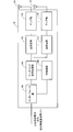
- FIG. 7 is an overall configuration diagram of the radio base station 10 according to the present embodiment.
- the radio base station 10 includes a plurality of transmission / reception antennas 101 for MIMO transmission, an amplifier unit 102, a transmission / reception unit (transmission unit) 103, a baseband signal processing unit 104, a call processing unit 105, an interface unit 106, It has.
- User data transmitted from the radio base station 10 to the user terminal 20 via the downlink is input from the higher station apparatus 30 to the baseband signal processing unit 104 via the interface unit 106.
- the baseband signal processing unit 104 performs PDCP layer processing, user data division / combination, RLC layer transmission processing such as RLC (Radio Link Control) retransmission control transmission processing, MAC (Medium Access Control) retransmission control, for example, HARQ transmission processing, scheduling, transmission format selection, channel coding, Inverse Fast Fourier Transform (IFFT) processing, precoding processing, and the like are performed and transferred to the transmission / reception section 103.
- RLC layer transmission processing such as RLC (Radio Link Control) retransmission control transmission processing, MAC (Medium Access Control) retransmission control, for example, HARQ transmission processing, scheduling, transmission format selection, channel coding, Inverse Fast Fourier Transform (IFFT) processing, precoding processing, and the like are performed and transferred to the transmission / reception section 103.
- RLC layer transmission processing such as RLC (Radio Link Control) retransmission control transmission processing, MAC (Medium Access Control) retransmission control, for example, HARQ transmission processing, scheduling, transmission format
- Each transmitting / receiving unit 103 converts the downlink signal output by precoding from the baseband signal processing unit 104 for each antenna to a radio frequency band.
- the amplifier unit 102 amplifies the frequency-converted radio frequency signal and transmits the amplified signal using the transmitting / receiving antenna 101.
- each radio frequency signal received by the transmission / reception antenna 101 is amplified by the amplifier unit 102, converted in frequency by the transmission / reception unit 103, converted into a baseband signal, and input to the baseband signal processing unit 104.
- the baseband signal processing unit 104 performs FFT processing, IDFT processing, error correction decoding, MAC retransmission control reception processing, RLC layer, and PDCP layer reception processing on user data included in the input uplink signal.
- the data is transferred to the higher station apparatus 30 via the interface unit 106.
- the call processing unit 105 performs call processing such as communication channel setting and release, base station state management, and radio resource management.
- the interface unit 106 transmits and receives signals (backhaul signaling) to and from an adjacent base station via an inter-base station interface (for example, optical fiber, X2 interface). For example, data transmission / reception between the master base station 11 and the secondary base station 12 is performed via the interface unit 106. Alternatively, the interface unit 106 transmits and receives signals to and from the higher station apparatus 30 via a predetermined interface.
- an inter-base station interface for example, optical fiber, X2 interface.
- FIG. 8 is a functional configuration diagram of the master base station 11 according to the present embodiment.
- the following functional configuration is mainly configured by the baseband signal processing unit 104 included in the master base station 11 and the like.
- the master base station 11 includes a scheduler 301 and a DL signal generation unit 302.
- the necessary configuration is provided without a shortage.
- the scheduler 301 allocates (schedules) radio resources for DL signals transmitted to the user terminals 20 and radio resources for UL signals transmitted by the user terminals 20.
- the scheduler 301 changes the DRX state of the user terminal 20 to the secondary base station 12 in response to the occurrence of traffic for the user terminal 20 in the master base station 11 and the secondary base station 12. I have control.
- the scheduler 301 When traffic for the user terminal 20 occurs in the master base station 11 or the secondary base station 12, the scheduler 301 generates a DL signal generation unit 302 so as to generate instruction information for causing the user terminal 20 in the DRX state to transition to the Non-DRX state. To instruct.
- the DL signal generation unit 302 includes a data signal generation unit 303 that generates a data signal for the user terminal 20 and an instruction information generation unit (generation unit) 304 that generates instruction information for the user terminal 20.
- the data signal generation unit 303 generates a data signal when a packet is input through the interface unit 106.
- the instruction information generation unit 304 generates instruction information when a data signal is generated by the data signal generation unit 303 or when a data signal is generated by the secondary base station 12.
- the instruction information of the first operation method is information for causing the user terminal 20 to start a contention-based or non-contention-based RACH procedure (random access).
- the instruction information of the second operation method is information for forcibly starting the drx_Inactivity Timer in the user terminal 20.
- the signals generated by the data signal generation unit 303 and the instruction information generation unit 304 are transmitted to the user terminal 20 via the transmission / reception unit 103.
- the instruction information may be transmitted by the transmitter / receiver 103 by any of MAC signaling, RRC signaling, and PDCCH.
- the scheduler 301 instructs the secondary base station 12 to start the RACH procedure of PDCCH-order when instructing activation of the drx_Inactivity Timer.
- FIG. 9 is a functional configuration diagram of the secondary base station 12 according to the present embodiment.
- the following functional configuration is mainly configured by the baseband signal processing unit 104 and the like included in the secondary base station 12.
- the secondary base station 12 includes a scheduler 311 and a DL signal generation unit 312.
- the necessary configuration is provided without a shortage.
- the scheduler 311 performs allocation (scheduling) of radio resources for DL signals transmitted to the user terminals 20 and radio resources for UL signals transmitted by the user terminals 20. For example, DS transmission is scheduled in accordance with the DRX reception section of the user terminal 20 (see FIG. 4).
- the scheduler 311 controls the DRX state of the user terminal 20 with respect to the secondary base station 12 according to the occurrence of traffic for the user terminal 20 in the master base station 11 and the secondary base station 12.
- the scheduler 311 instructs the DL signal generation unit 312 to generate a DS for Non-DRX transition.
- the DL signal generation unit 312 includes a data signal generation unit 313 that generates a data signal for the user terminal 20 and a DS generation unit (generation unit) 314 that generates a DS for the user terminal 20.
- the data signal generation unit 313 generates a data signal when a packet is input through the interface unit 106.
- the DS generation unit 314 generates a normal carrier detection DS. Also, the DS generation unit 314 generates a DS for Non-DRX transition when the data signal is generated by the data signal generation unit 313 or when the data signal is generated by the secondary base station 12.
- the non-DRX transition DS of the third operation method is generated by a scramble sequence different from the normal DS.
- the DS for Non-DRX transition instructs the user terminal 20 to start the RACH procedure, start drx_Inactivity Timer, or transition to Short DRX.
- the start of the RACH procedure is instructed by the non-DRX transition DS, the user terminal 20 transitions from the DRX state to the Non-DRX state.
- the DS for Non-DRX transition is transmitted in the same subframe as the normal DS, but may be set with a smaller number of transmissions (in a long cycle) than the normal DS. That is, the normal DS and the non-DRX transition DS may be transmitted in some of the subframes in which the normal DS is transmitted. Thereby, it is possible to reduce the load of the DS detection process on the user terminal 20 side.
- the signals generated by the data signal generation unit 313 and the DS generation unit 314 are transmitted to the user terminal 20 via the transmission / reception unit 103.
- the DL signal generation unit 312 also generates a RACH signal (RACH response, dedicated preamble) used in the RACH procedure between the user terminal 20 and the secondary base station 12.
- RACH response dedicated preamble
- the instruction information may be generated by the DS generation unit 314 of the secondary base station 12 and the instruction information may be transmitted from the master base station 11 to the user terminal 20.
- FIG. 10 is an overall configuration diagram of the user terminal 20 according to the present embodiment.
- the user terminal 20 includes a plurality of transmission / reception antennas 201 for MIMO transmission, an amplifier unit 202, a transmission / reception unit (reception unit) 203, a baseband signal processing unit 204, and an application unit 205.
- radio frequency signals received by a plurality of transmission / reception antennas 201 are each amplified by an amplifier unit 202, converted in frequency by a transmission / reception unit 203, and converted into a baseband signal.
- the baseband signal is subjected to FFT processing, error correction decoding, retransmission control reception processing, and the like by the baseband signal processing unit 204.
- downlink user data is transferred to the application unit 205.
- the application unit 205 performs processing related to layers higher than the physical layer and the MAC layer. Also, broadcast information in the downlink data is also transferred to the application unit 205.
- uplink user data is input from the application unit 205 to the baseband signal processing unit 204.
- transmission processing for retransmission control H-ARQ (Hybrid ARQ)
- channel coding precoding
- DFT processing IFFT processing
- the like are performed and transferred to each transmission / reception unit 203.
- the transmission / reception unit 203 converts the baseband signal output from the baseband signal processing unit 204 into a radio frequency band.
- the amplifier unit 202 amplifies the frequency-converted radio frequency signal and transmits the amplified signal using the transmitting / receiving antenna 201.
- FIG. 11 is a functional configuration diagram of the user terminal 20 according to the present embodiment.
- the following functional configuration is mainly configured by the baseband signal processing unit 204 included in the user terminal 20.
- the user terminal 20 includes a DL signal decoding unit 401, a state transition unit 402, a random access control unit 403, a cell detection / measurement unit (detection unit) 404, and a UL signal generation unit 405.
- DL signal decoding unit 401 As illustrated in FIG. 11, the user terminal 20 includes a DL signal decoding unit 401, a state transition unit 402, a random access control unit 403, a cell detection / measurement unit (detection unit) 404, and a UL signal generation unit 405.
- a cell detection / measurement unit detection unit
- the DL signal decoding unit 401 decodes the DL signals transmitted from the master base station 11 and the secondary base station 12. For example, the instruction information transmitted from the master base station 11 and the DS transmitted from the secondary base station 12 are acquired. The instruction information is output from the DL signal decoding unit 401 to the state transition unit 402, and the DS is output from the DL signal decoding unit 401 to the cell detection / measurement unit 404.
- the state transition unit 402 transitions from the DRX state to the Non-DRX state immediately.
- the state transition unit 402 transitions from the DRX state to the Non-DRX state based on the instruction information.
- the random access control unit 403 is instructed to start the RACH procedure based on the instruction information, and transitions from the DRX state to the Non-DRX state.
- the drx_Inactivity Timer is activated to transition from the DRX state to the Non-DRX state.
- the user terminal 20 monitors the PDCCH from the secondary base station 12 until a predetermined period elapses.
- the cell detection / measurement unit 404 blindly detects the DS received from the secondary base station 12.
- an instruction to start the RACH procedure, an instruction to start drx_Inactivity Timer, an instruction to transition to Short DRX, etc. are output to the state transition unit 402 Then, the user terminal 20 is changed to the Non-DRX state.
- the cell detection / measurement unit 404 measures a reception state (RSRP, RSRQ, etc.) for the DS. The measurement result is fed back to the master base station 11 and the secondary base station 12 as a measurement report.
- the random access control unit 403 controls a random access procedure. For example, the random access control unit 403 controls the PRACH signal based on the instruction information transmitted from the master base station 11 and the trigger (Dedicated preamble) of the RACH signal transmitted on the PDCCH from the secondary base station 12.
- the UL signal generation unit 405 generates an UL signal (such as a PRACH signal or a measurement report) based on instructions from the random access control unit 403 and the cell detection / measurement unit 404.
- the UL signal generation unit 405 generates an uplink control signal such as a delivery confirmation signal and an uplink data signal.
- instruction traffic is transmitted from the master base station 11 to the user terminal 20 when traffic of the master base station 11 or the secondary base station 12 occurs in Dual connectivity. Is done.
- the user terminal 20 transitions from the DRX state for the secondary base station 12 to the Non-DRX state by receiving the instruction information. For this reason, the start operation of the data communication of the user terminal 20 with respect to the secondary base station 12 does not depend on the period of the reception timing in the DRX state, and the data communication is started early between the user terminal 20 and the secondary base station 12 Can be made.
- the present invention is not limited to the above embodiment, and can be implemented with various modifications.
- the number of carriers, the carrier bandwidth, the signaling method, the number of processing units, and the processing procedure in the above description can be appropriately changed and implemented without departing from the scope of the present invention.
- Other modifications can be made without departing from the scope of the present invention.
Abstract
Dual connectivityにおいて基地局側のトラヒック発生時のデータ通信の開始動作の最適化を図ること。セカンダリ基地局(12)で用いられる第1のキャリアにおいてユーザ端末(20)がDRX状態であり、第2のキャリアを用いてユーザ端末と通信するマスタ基地局(11)が、自局又はセカンダリ基地局でトラヒックが発生した場合に、ユーザ端末をDRX状態からNon-DRX状態に遷移させる指示情報をユーザ端末に送信する構成にした。
Description
本発明は、次世代移動通信システムにおける無線基地局、ユーザ端末及び無線通信方法に関する。
従来、無線通信システムでは、様々な無線通信方式が用いられている。例えば、W-CDMA(Wideband Code Division Multiple Access)とも呼ばれるUMTS(Universal Mobile Telecommunications System)では、符号分割多元接続(CDMA:Code Division Multiple Access)が用いられる。また、LTE(Long Term Evolution)では、直交周波数分割多元接続(OFDMA:Orthogonal Frequency Division Multiple Access)が用いられる(例えば、非特許文献1)。
また、LTEからのさらなる広帯域化及び高速化を目的として、LTEの後継システムも検討されてきた(例えば、LTEアドバンスト又はLTEエンハンスメントと呼ぶこともある(以下、「LTE-A」という))。LTE-Aシステムでは、半径数キロメートル程度の広範囲のカバレッジエリアを有するマクロセル内に、半径数十メートル程度の局所的なカバレッジエリアを有するスモールセルが形成されるHetNet(Heterogeneous Network)が検討されている。
3GPP TR 25.913"Requirements for Evolved UTRA and Evolved UTRAN"
ところで、Rel-12においては、複数のセルが異なる周波数帯(キャリア)で用いられるシナリオが検討されている。複数のセルの基地局が実質同一の場合には、キャリアアグリゲーション(intra-eNB CA)が適用可能である。一方で、複数のセルの基地局が完全に異なる場合には、Dual connectivity(inter-eNB CA)を行うことが考えられる。Dual connectivityでは、バッテリー消費の観点から基地局毎にDRX(Discontinuous Reception)が設定される。基地局側のトラヒック発生時にはデータ通信の開始がDRXサイクルに依存するため、Dual connectivityについてはデータ通信の開始動作の最適化が課題として残っている。
本発明はかかる点に鑑みてなされたものであり、Dual connectivityにおいて基地局側のトラヒック発生時のデータ通信の開始動作の最適化を図ることができる無線基地局、ユーザ端末及び無線通信方法を提供することを目的とする。
本発明の無線基地局は、他の無線基地局で用いられる第1のキャリアにおいてユーザ端末が間欠受信状態であり、前記他の無線基地局とは異なる第2のキャリアを用いて前記ユーザ端末と通信する無線基地局であって、自局又は前記他の無線基地局でトラヒックが発生した場合に、前記ユーザ端末を間欠受信状態から非間欠受信状態に遷移させる指示情報を前記ユーザ端末に送信する送信部を備えることを特徴とする。
本発明によれば、Dual connectivityにおいて無線基地局又は他の無線基地局のトラヒックの発生時には、無線基地局からユーザ端末に指示情報が送信される。ユーザ端末は指示情報の受信によって第1のキャリアについて間欠受信状態から非間欠受信状態に遷移する。このため、第1のキャリアにおけるユーザ端末のデータ通信の開始動作が間欠受信状態の受信タイミングの周期に依存することがなく、ユーザ端末と他の無線基地局との間で早期にデータ通信を開始させることができる。
図1は、HetNetの概念図である。図1に示すように、HetNetは、マクロセルMとスモールセルSとの少なくとも一部が地理的に重複して配置される無線通信システムである。HetNetは、マクロセルMを形成する無線基地局(以下、マクロ基地局という)eNB1と、スモールセルSを形成する無線基地局(以下、スモール基地局という)eNB2と、マクロ基地局eNB1とスモール基地局eNB2と通信するユーザ端末UEとを含んで構成される。なお、スモールセルSは、ファントムセル、ピコセル、ナノセル、フェムトセル、マイクロセルを含む概念である。
HetNet構成では、トラヒックのさらなる増大をサポートするために、高密度にスモールセルSを展開するシナリオが検討されている。このシナリオでは、マクロセルMに相対的に低い周波数帯のキャリアが用いられ、スモールセルSに相対的に高い周波数帯のキャリアが用いられる。マクロセルレイヤでは、Control-planeの接続を確立して、低い周波数帯で高い送信電力密度をサポートすることで広いカバレッジやモビリティが確保される。一方で、高密度スモールセルレイヤでは、データに特化したUser-planeの接続を確立して、高い周波帯でキャパシティを確保することでスループットが増大される。
上記シナリオを実現する方法としては、マクロセルMとスモールセルSとをバックホールで接続することが理想であり、マクロセルMとスモールセルSとが実質的に同一基地局、すなわちスケジューラが共通の場合にはCarrier Aggregation(Rel-10)(以下、Rel-10 CAという)が適用される。Rel-10 CAでは、サービングセルをPCell(Primary Cell)とし、PCellとは別の周波数帯に存在するSCell(Secondary Cell)を用いて通信が行われる。ユーザ端末UEには、SCellで通信がない場合に、SCellを非アクティブ化(deactivate)する機能がサポートされている。
SCellの非アクティブ状態では、例えば、ユーザ端末UEはSRS(Sounding Reference Signal)の送信やPDCCH(Physical Downlink Control Channel)で下り制御信号の受信が行われない。このため、ユーザ端末UEのバッテリー消費が抑えられている。SCellのアクティブ化/非アクティブ化はMACシグナリングによって行われており、比較的動的に制御することが可能になっている。SCellがアクティブ化(activate)されると、ユーザ端末UEがCQIの測定等を実施して通信が行われる。なお、Rel-10 CAはIntra-eNB CAと呼ばれてもよい。
一方でマクロセルMとスモールセルSとが別基地局、すなわちスケジューラが異なる場合には、Rel-10 CAの代わりにDual Connectivityが適用される。Dual Connectivityでは、マスタ基地局(Master eNB)MeNBに加えて、セカンダリ基地局(Secondary eNB)をユーザ端末UEに設定することで実現される。Dual Connectivityは、基地局毎にDRX(Discontinuous Reception)を設定することで、ユーザ端末UEのバッテリー消費が抑えられている。なお、Dual Connectivityはinter-eNB CAと呼ばれてもよい。
図2に示すように、DRX状態(間欠受信状態)のユーザ端末UEは、所定のDRXサイクルで周期的に起動されて、受信区間(on-duration)で、下り制御信号(PDCCH)をモニターしている。端末側でトラヒックが発生した場合には、DRX状態のユーザ端末UEからScheduling requestを送信して上りリンクの通信が直ちに再開される。また、NW側(基地局側)でトラヒックが発生した場合には、DRX状態のユーザ端末UEが受信区間で下り制御信号を受信して下りリンクの通信が再開される。
上記したように、Rel-10 CAは、MACシグナリングによってSCellのアクティブ化/非アクティブ化を動的に制御することが可能である。したがって、NW側でトラヒックが発生した場合でも、非アクティブ状態のSCellを即時起動させてデータ通信を再開させることができる。しかしながら、Dual ConnectivityにおいてNW側でのトラヒック発生時には、DRXの受信区間で下り制御信号を受信しなければならず、データ通信の開始動作がDRXサイクルに依存してしまっていた。以下、本発明について説明する前に、一般的なDual Connectivityのデータ通信の開始動作について具体的に説明する。
図3は、Dual Connectivityにおけるユーザ端末UEのデータ通信の開始動作の一例である。先ず、RRC接続モードのユーザ端末UEがマクロセルMのマスタ基地局MeNBと通信する(ステップST01)。次に、ユーザ端末UEには、検出測定信号としてのDiscovery Signal(以下、DSという)を受信するためのアシスト情報(送信タイミング、送信周期、送信周波数、信号構成等のパラメータ)がマスタ基地局MeNBから通知される。そして、ユーザ端末UEは、アシスト情報に基づいてDSを受信してマスタ基地局MeNBのキャリアとは異なる周波数帯のキャリアにおいてメジャメントを行う(ステップST02)。
次に、ユーザ端末UEは、DSによって得られたメジャメントレポートをマスタ基地局MeNBにフィードバックする(ステップST03)。次に、メジャメントレポートに基づいて、ユーザ端末UEには、例えばRSRP(Reference Signal Received Power)の高いセカンダリ基地局SeNBが割り当てられる。このとき、ユーザ端末UEには、スモールセルSのON/OFFに関わらずDRXも設定される(ステップST04)。次に、NW側でトラヒックが発生すると、DRX状態のユーザ端末UEが受信区間でPDCCHを読みに行く(ステップS05)。これにより、スモールセルSがOFFの場合にはONになる。
そして、ユーザ端末UEは、同期、RACH(Random Access Channel)手順、CSI(Channel State Information)メジャメントを実施し(ステップST06)、セカンダリ基地局SeNBから下りデータを受信する(ステップST07)。このように、Dual Connectivityでは、NW側からユーザ端末UEがDSを受信してメジャメントを行うことで、ユーザ端末UEに対してセカンダリ基地局SeNBと共にDRXが設定される。このため、NW側でトラヒックが発生した場合には、DRXの受信区間まで待って後続のRACH手順等が実施される。
図4に示す例では、セカンダリ基地局SeNB(スモールセルS)についてDSの受信期間が200msec置きに2msec、DRXサイクルが40msec、DRXの受信区間(on-duration)が2msecに設定されている。この場合、ユーザ端末UE側でトラヒックが発生する場合には、DRXの受信区間を待つことなく、RACH手順後に直ちに上りリンクのデータ通信が開始される。一方、受信区間直後にNW側でトラヒックが発生する場合には、トラヒックが発生してから次の受信区間まで待たなければ、RACH手順等の接続動作を開始することができなかった。
特に、Long DTX(Discontinuous Transmission)では、データ通信の開始までに時間がかかってしまっていた。このように、Dual Connectivityにおいては、NW側のトラヒック発生時のデータ通信の開始動作の最適化が十分には図られていない。そこで、本発明者らは、下りリンクのデータ通信の開始がDRXサイクルに依存して遅延するのを改善するために、本発明に至った。すなわち、本発明の骨子は、NW側のトラヒック発生時には、NW側の制御によってユーザ端末UEをDRX状態からNon-DRX状態に遷移させて、セカンダリ基地局SeNB(スモールセルS)について早期にデータ通信を開始させることである。
以下、図5を参照して、本実施の形態に係るセカンダリ基地局12に対するユーザ端末20のデータ通信の開始動作について説明する。データ通信の開始動作の動作方法としては、以下の3つの方法が考えられる。第1の動作方法は、ユーザ端末20にセカンダリ基地局12に対するRACH手順(ランダムアクセス手順)を起動させる方法である。第2の動作方法は、ユーザ端末20にセカンダリ基地局12に対するdrx_Inactivity Timerを起動させる方法である。第3の動作方法は、特定のDSによってユーザ端末20にDRX状態からNon-DRX状態に遷移させる方法である。
以下の第1から第3の動作方法の説明では、ユーザ端末20にはDual Connectivityが適用されているものとする。そして、第1のキャリア(例えば、相対的に低い周波数帯のキャリア)では、ユーザ端末20がマスタ基地局11と通信可能になっている。第2のキャリア(例えば、相対的に高い周波数帯のキャリア)では、ユーザ端末20がセカンダリ基地局12に対してDRX状態になっている。また、データ通信の開始動作の動作方法は、上記3つの動作方法に限定されるものではなく、NW側の制御によってユーザ端末20をDRX状態からNon-DRX状態に動的に遷移させる方法であればよい。
図5Aは、マスタ基地局11でトラヒック(パケット)が発生した場合の第1の動作方法を示している。マスタ基地局11でトラヒックが発生すると、マスタ基地局11からユーザ端末20に、セカンダリ基地局12に対するRACH手順の開始を指示するための指示情報が通知される。ユーザ端末20はマスタ基地局11から指示情報を受信すると、DRX状態からNon-DRX状態に遷移する。そして、セカンダリ基地局12に対してRACH手順を開始し、さらにCSIメジャメントを実施する。これにより、DRXサイクルに依存することなく、ユーザ端末20とセカンダリ基地局12との間で早期にデータ通信が開始される。
なお、第1の動作方法では、コンテンションベースのRACH手順の開始を指示するための指示情報がユーザ端末20に通知されてもよいし、非コンテンションベースのRACH手順の開始を指示するための指示情報がユーザ端末20に通知されてもよい。コンテンションベースのRACH手順の場合には、セカンダリ基地局12においてRACHを常にモニターするようにする。この場合、マスタ基地局11からセカンダリ基地局12に対して、ユーザ端末20に対してRACH手順の開始を指示したことをバックホールに通知してもよい。これにより、セカンダリ基地局12が常にRACHをモニターする必要がなくなり、セカンダリ基地局12の負荷が低減される。
また、非コンテンションベースのRACH手順の場合には、破線に示すようにセカンダリ基地局12からマスタ基地局11にバックホールでRACHのプリアンブルを指定するようにする。マスタ基地局11を介して指定されたプリアンブルがユーザ端末20からセカンダリ基地局12に送信されるため、プリアンブルのコンテンションが抑えられる。なお、指示情報は、MACシグナリング、RRCシグナリング、PDCCHのいずれを用いて、マスタ基地局11からユーザ端末20に通知されてもよい。
図5Bは、セカンダリ基地局12でトラヒック(パケット)が発生した場合の第1の動作方法を示している。セカンダリ基地局12でトラヒックが発生すると、セカンダリ基地局12においてRACHに関する上位レイヤメッセージが生成される。上位レイヤメッセージはセカンダリ基地局12からマスタ基地局11にバックホールで通知される。マスタ基地局11で上位レイヤメッセージを受けて、マスタ基地局11からユーザ端末20に、セカンダリ基地局12に対するRACH手順の開始を指示するための指示情報が通知される。
ユーザ端末20はマスタ基地局11から指示情報を受信すると、DRX状態からNon-DRX状態に遷移する。そして、セカンダリ基地局12に対してRACH手順を開始し、さらにCSIメジャメントを実施する。これにより、DRXサイクルに依存することなく、ユーザ端末20とセカンダリ基地局12との間で早期にデータ通信が開始される。なお、セカンダリ基地局12でトラヒックが発生した場合においても、マスタ基地局11でトラヒックが発生した場合と同様に、コンテンションベース又は非コンテンションベースの指示情報が通知されてもよい。
また、セカンダリ基地局12でトラヒックが発生した場合には、セカンダリ基地局12において具体的なシグナリング内容を含む指示情報が生成され、マスタ基地局11はこれをユーザ端末20に転送するように構成されてもよい。また、セカンダリ基地局12においてRACH手順の起動指示だけが生成され、ユーザ端末20に対する具体的なシグナリング内容(指示情報)についてはマスタ基地局11で生成されてもよい。なお、指示情報は、MACシグナリング、RRCシグナリング、PDCCHのいずれを用いて、マスタ基地局11からユーザ端末20に通知されてもよい。
図5Cは、マスタ基地局11でトラヒック(パケット)が発生した場合の第2の動作方法を示している。マスタ基地局11でトラヒックが発生すると、マスタ基地局11からユーザ端末20に、drx_Inactivity Timerを起動するための指示情報が通知される。ユーザ端末20はマスタ基地局11から指示情報を受信すると、drx_Inactivity Timerを起動してDRX状態からNon-DRX状態に遷移する。このdrx_Inactivity Timerによって、ユーザ端末20は一定期間経過するまでセカンダリ基地局12のPDCCHをモニターすることになる。
また、マスタ基地局11は、PDCCH-orderのRACH手順の開始をセカンダリ基地局12に指示する。セカンダリ基地局12は、PDCCH等を用いてユーザ端末20に対してRACHの送信指示を行う(Dedicated preamble)。ユーザ端末20は、PDCCHを用いたセカンダリ基地局12からの指示により、RACH手順を実施すると共に、CSIメジャメントを実施する。これにより、DRXサイクルに依存することなく、ユーザ端末20とセカンダリ基地局12との間で早期にデータ通信が開始される。
なお、第2の動作方法においては、マスタ基地局11でトラヒックが発生する構成について説明したが、この構成に限定されない。第2の動作方法は、セカンダリ基地局12でトラヒックが発生する構成にも適用可能である。また、指示情報は、MACシグナリング、RRCシグナリング、PDCCHのいずれを用いて、マスタ基地局11からユーザ端末20に通知されてもよい。
図5Dは、セカンダリ基地局12でトラヒック(パケット)が発生した場合の第3の動作方法を示している。セカンダリ基地局12は、通常のキャリア検出用のDSの他に、特定のDSを所定周期でユーザ端末20に送信する。特定のDSとしては、通常のDSとは異なるスクランブル系列から生成されたNon-DRX遷移用のDSが用意される。ユーザ端末20はNon-DRX遷移用のDSを検出した場合にDRX状態からNon-DRX状態に遷移する。このDRX状態からNon-DRX状態への遷移は、RACH手順の開始、drx_Inactivity Timerの起動、Short DRXのいずれを用いて実施されてもよい。
その後、セカンダリ基地局12に対してRACH手順を開始し、さらにCSIメジャメントを実施する。これにより、DRXサイクルに依存することなく、ユーザ端末20とセカンダリ基地局12との間で早期にデータ通信が開始される。特に、第3の動作方法では、DSの送信周期よりもDRXの周期が長い場合に有効である。
なお、通常のDSが送信されるサブフレームの他に、通常のDSとNon-DRX遷移用のDSが送信される特定のサブフレームが設定される構成にしてもよい。この場合、ユーザ端末20は、特定のサブフレームにおいて通常のDSとNon-DRX遷移用のDSを検出し、Non-DRX遷移用のDSを検出した場合には直ちにDRX状態からNon-DRX状態に遷移する。これにより、ユーザ端末20のブラインド検出処理の回数を減らすことができる。なお、第3の動作方法においては、セカンダリ基地局12でトラヒックが発生する構成について説明したが、この構成に限定されない。第3の動作方法は、マスタ基地局11でトラヒックが発生する構成にも適用可能である。
以下、本実施の形態に係る無線通信システムについて、詳細に説明する。図6は、本実施の形態に係る無線通信システムの概略構成図である。なお、図6に示す無線通信システムは、例えば、LTEシステム或いは、SUPER 3Gが包含されるシステムである。この無線通信システムでは、LTEシステムのシステム帯域幅を1単位とする複数の基本周波数ブロック(コンポーネントキャリア)を一体としたキャリアアグリゲーションを適用することができる。また、この無線通信システムは、IMT-Advancedと呼ばれても良いし、4G、FRA(Future Radio Access)と呼ばれても良い。
図6に示す無線通信システム1は、マクロセルMを形成するマスタ基地局11と、マクロセルM内に配置され、マクロセルMよりも狭いスモールセルSを形成するセカンダリ基地局12を備えている。マクロセルM及び各スモールセルSには、ユーザ端末20が配置されている。ユーザ端末20は、マスタ基地局11及びセカンダリ基地局12の双方に接続することができる。マクロセルMでは相対的に低い周波数帯域(例えば、2GHz)で帯域幅が狭いキャリア(Legacy carrier等と呼ばれる)が使用されている。一方、スモールセルSでは相対的に高い周波数帯域(例えば、3.5GHz等)で帯域幅が広いキャリアが用いられている。
ユーザ端末20は、Dual Connectivityによって、相対的に低い周波数帯域でマスタ基地局11と通信し、相対的に高い周波数帯域でセカンダリ基地局12と通信する。マスタ基地局11とセカンダリ基地局12は、基地局間インターフェース(例えば、光ファイバ、X2インターフェース等)を介して互いに接続される。また、マクロセルMとスモールセルSは、同周波のキャリアが用いられてもよい。マスタ基地局11及びセカンダリ基地局12は、それぞれ上位局装置30に接続され、上位局装置30を介してコアネットワーク40に接続される。なお、上位局装置30には、例えば、アクセスゲートウェイ装置、無線ネットワークコントローラ(RNC)、モビリティマネジメントエンティティ(MME)等が含まれるが、これに限定されるものではない。
なお、マスタ基地局11は、eNodeB、送受信ポイント(transmission point)などと呼ばれてもよい。また、セカンダリ基地局12は、ピコ基地局、フェムト基地局、Home eNodeB、RRH(Remote Radio Head)、マイクロ基地局、送受信ポイントなどと呼ばれてもよい。また、スモールセルSをカバーする基地局をマスタ基地局11とし、マクロセルMをカバーする基地局をセカンダリ基地局12としてもよい。各ユーザ端末20は、LTE、LTE-Aなどの各種通信方式に対応した端末であり、移動通信端末だけでなく固定通信端末を含んでよい。
無線通信システム1においては、無線アクセス方式として、下りリンクについてはOFDMA(直交周波数分割多元接続)が適用され、上りリンクについてはSC-FDMA(シングルキャリア-周波数分割多元接続)が適用される。
無線通信システム1では、下りリンクの通信チャネルとして、各ユーザ端末20で共有される下り共有チャネル(PDSCH:Physical Downlink Shared Channel)と、下り制御チャネル(PDCCH:Physical Downlink Control Channel、EPDCCH:Enhanced Physical Downlink Control Channel)、PCFICH(Physical Control Format Indicator Channel)、PHICH(Physical Hybrid-ARQ Indicator Channel)、報知チャネル(PBCH)などが用いられる。PDSCHにより、ユーザデータや上位レイヤ制御情報が伝送される。PDCCH、EPDCCHにより、下り制御情報(DCI)が伝送される。
また、無線通信システム1では、上りリンクの通信チャネルとして、各ユーザ端末20で共有される上り共有チャネル(PUSCH:Physical Uplink Shared Channel)と、上り制御チャネル(PUCCH:Physical Uplink Control Channel)などが用いられる。PUSCHにより、ユーザデータや上位レイヤ制御情報が伝送される。また、PUCCHにより、下りリンクの無線品質情報(CQI:Channel Quality Indicator)や、送達確認情報(ACK/NACK)等が伝送される。
以下、マスタ基地局11及びセカンダリ基地局12を区別しない場合、無線基地局10と総称する。図7は、本実施の形態に係る無線基地局10の全体構成図である。無線基地局10は、MIMO伝送のための複数の送受信アンテナ101と、アンプ部102と、送受信部(送信部)103と、ベースバンド信号処理部104と、呼処理部105と、インターフェース部106とを備えている。
下りリンクにより無線基地局10からユーザ端末20に送信されるユーザデータは、上位局装置30からインターフェース部106を介してベースバンド信号処理部104に入力される。
ベースバンド信号処理部104では、PDCPレイヤの処理、ユーザデータの分割・結合、RLC(Radio Link Control)再送制御の送信処理などのRLCレイヤの送信処理、MAC(Medium Access Control)再送制御、例えば、HARQの送信処理、スケジューリング、伝送フォーマット選択、チャネル符号化、逆高速フーリエ変換(IFFT:Inverse Fast Fourier Transform)処理、プリコーディング処理等が行われて送受信部103に転送される。また、制御信号に関しても、チャネル符号化や逆高速フーリエ変換等の送信処理が行われて、送受信部103に転送される。
各送受信部103は、ベースバンド信号処理部104からアンテナ毎にプリコーディングして出力された下り信号を無線周波数帯に変換する。アンプ部102は、周波数変換された無線周波数信号を増幅して送受信アンテナ101により送信する。
一方、上り信号については、送受信アンテナ101で受信された無線周波数信号がそれぞれアンプ部102で増幅され、送受信部103で周波数変換されてベースバンド信号に変換され、ベースバンド信号処理部104に入力される。
ベースバンド信号処理部104では、入力された上り信号に含まれるユーザデータに対して、FFT処理、IDFT処理、誤り訂正復号、MAC再送制御の受信処理、RLCレイヤ、PDCPレイヤの受信処理がなされ、インターフェース部106を介して上位局装置30に転送される。呼処理部105は、通信チャネルの設定や解放等の呼処理や、基地局の状態管理や、無線リソースの管理を行う。
インターフェース部106は、基地局間インターフェース(例えば、光ファイバ、X2インターフェース)を介して隣接基地局と信号を送受信(バックホールシグナリング)する。例えば、マスタ基地局11とセカンダリ基地局12間のデータの送受信を、インターフェース部106を介して行う。あるいは、インターフェース部106は、所定のインターフェースを介して、上位局装置30と信号を送受信する。
図8は、本実施の形態に係るマスタ基地局11の機能構成図である。なお、以下の機能構成は、主にマスタ基地局11が有するベースバンド信号処理部104などによって構成される。図8に示すように、マスタ基地局11は、スケジューラ301、DL信号生成部302を有する。ここでは、ベースバンド信号処理部104の一部の構成のみを示しているが、必要な構成を不足なく備えているものとする。
スケジューラ301は、ユーザ端末20に送信するDL信号用の無線リソース、ユーザ端末20が送信するUL信号用の無線リソースの割当て(スケジューリング)を行う。上記した第1、第2の動作方法では、スケジューラ301は、マスタ基地局11及びセカンダリ基地局12におけるユーザ端末20向けのトラヒックの発生に応じて、ユーザ端末20のセカンダリ基地局12に対するDRX状態を制御している。スケジューラ301は、マスタ基地局11又はセカンダリ基地局12でユーザ端末20向けのトラヒックが発生すると、DRX状態のユーザ端末20をNon-DRX状態に遷移させる指示情報を生成するようにDL信号生成部302に指示する。
DL信号生成部302は、ユーザ端末20向けのデータ信号を生成するデータ信号生成部303と、ユーザ端末20向けの指示情報を生成する指示情報生成部(生成部)304とを含んでいる。データ信号生成部303は、インターフェース部106を通じてパケットが入力された場合にデータ信号を生成する。指示情報生成部304は、データ信号生成部303でデータ信号が生成された場合、又はセカンダリ基地局12でデータ信号が生成された場合に指示情報を生成する。
この場合、第1の動作方法の指示情報は、ユーザ端末20にコンテンションベース又は非コンテンションベースのRACH手順(ランダムアクセス)を開始させるための情報である。指示情報によってRACH手順の開始が指示されることで、ユーザ端末20がDRX状態からNon-DRX状態に遷移する。第2の動作方法の指示情報は、ユーザ端末20に強制的にdrx_Inactivity Timerを起動させるための情報である。指示情報によってdrx_Inactivity Timerの起動が指示されることで、ユーザ端末20がDRX状態からNon-DRX状態に一定期間遷移する。
データ信号生成部303及び指示情報生成部304で生成された信号は、送受信部103を介してユーザ端末20に送信される。指示情報は、送受信部103においてMACシグナリング、RRCシグナリング、PDCCHのいずれで送信されてもよい。なお、スケジューラ301は、drx_Inactivity Timerの起動を指示する場合には、PDCCH-orderのRACH手順の開始をセカンダリ基地局12に指示する。
図9は、本実施の形態に係るセカンダリ基地局12の機能構成図である。なお、以下の機能構成は、主にセカンダリ基地局12が有するベースバンド信号処理部104などによって構成される。図9に示すように、セカンダリ基地局12は、スケジューラ311、DL信号生成部312を有する。ここでは、ベースバンド信号処理部104の一部の構成のみを示しているが、必要な構成を不足なく備えているものとする。
スケジューラ311は、ユーザ端末20に送信するDL信号用の無線リソース、ユーザ端末20が送信するUL信号用の無線リソースの割当て(スケジューリング)を行う。例えば、ユーザ端末20のDRXの受信区間に合わせて、DS送信をスケジューリングしている(図4参照)。第3の動作方法では、スケジューラ311は、マスタ基地局11及びセカンダリ基地局12におけるユーザ端末20向けのトラヒックの発生に応じて、ユーザ端末20のセカンダリ基地局12に対するDRX状態を制御している。スケジューラ311は、マスタ基地局11又はセカンダリ基地局12でユーザ端末20向けのトラヒックが発生すると、Non-DRX遷移用のDSを生成するようにDL信号生成部312に指示する。
DL信号生成部312は、ユーザ端末20向けのデータ信号を生成するデータ信号生成部313と、ユーザ端末20向けのDSを生成するDS生成部(生成部)314とを含んでいる。データ信号生成部313は、インターフェース部106を通じてパケットが入力された場合にデータ信号を生成する。DS生成部314は、通常のキャリア検出用のDSを生成する。また、DS生成部314は、データ信号生成部313でデータ信号が生成された場合、又はセカンダリ基地局12でデータ信号が生成された場合に、Non-DRX遷移用のDSを生成する。
この場合、第3の動作方法のNon-DRX遷移用のDSは、通常のDSとは異なるスクランブル系列によって生成されている。Non-DRX遷移用のDSは、例えば、RACH手順の開始、drx_Inactivity Timerの起動、Short DRXへの遷移のいずれかをユーザ端末20に指示する。Non-DRX遷移用のDSによって、RACH手順の開始等が指示されることで、ユーザ端末20がDRX状態からNon-DRX状態に遷移する。
なお、Non-DRX遷移用のDSは、通常のDSと同じサブフレームで送信されるが、通常のDSよりも送信回数が少なく(長周期に)設定されてもよい。すなわち、通常のDSが送信されるサブフレームのうち、一部のサブフレームで通常のDSとNon-DRX遷移用のDSが送信される構成にしてもよい。これにより、ユーザ端末20側におけるDSの検出処理の負担を軽減することが可能になっている。
データ信号生成部313及びDS生成部314で生成された信号は、送受信部103を介してユーザ端末20に送信される。なお、DL信号生成部312は、ユーザ端末20とセカンダリ基地局12との間のRACH手順で用いられるRACH信号(RACH response, Dedicated preamble)等も生成している。また、セカンダリ基地局12のDS生成部314で指示情報を生成し、マスタ基地局11からユーザ端末20に指示情報を送信させる構成にしてもよい。
図10は、本実施の形態に係るユーザ端末20の全体構成図である。ユーザ端末20は、MIMO伝送のための複数の送受信アンテナ201と、アンプ部202と、送受信部(受信部)203と、ベースバンド信号処理部204と、アプリケーション部205とを備えている。
下りリンクのデータについては、複数の送受信アンテナ201で受信された無線周波数信号がそれぞれアンプ部202で増幅され、送受信部203で周波数変換されてベースバンド信号に変換される。このベースバンド信号は、ベースバンド信号処理部204でFFT処理や、誤り訂正復号、再送制御の受信処理等がなされる。この下りリンクのデータの内、下りリンクのユーザデータは、アプリケーション部205に転送される。アプリケーション部205は、物理レイヤやMACレイヤより上位のレイヤに関する処理等を行う。また、下りリンクのデータの内、報知情報もアプリケーション部205に転送される。
一方、上りリンクのユーザデータについては、アプリケーション部205からベースバンド信号処理部204に入力される。ベースバンド信号処理部204では、再送制御(H-ARQ (Hybrid ARQ))の送信処理や、チャネル符号化、プリコーディング、DFT処理、IFFT処理等が行われて各送受信部203に転送される。送受信部203は、ベースバンド信号処理部204から出力されたベースバンド信号を無線周波数帯に変換する。その後、アンプ部202は、周波数変換された無線周波数信号を増幅して送受信アンテナ201により送信する。
図11は、本実施の形態に係るユーザ端末20の機能構成図である。なお、以下の機能構成は、主にユーザ端末20が有するベースバンド信号処理部204などによって構成される。図11に示すように、ユーザ端末20は、DL信号復号部401、状態遷移部402、ランダムアクセス制御部403、セル検出/測定部(検出部)404、UL信号生成部405を有している。ここでは、ベースバンド信号処理部204の一部の構成のみを示しているが、必要な構成を不足なく備えているものとする。
DL信号復号部401は、マスタ基地局11、セカンダリ基地局12から送信されたDL信号を復号する。例えば、マスタ基地局11から送信された指示情報や、セカンダリ基地局12から送信されるDSを取得する。指示情報はDL信号復号部401から状態遷移部402に出力され、DSはDL信号復号部401からセル検出/測定部404に出力される。
状態遷移部402は、アプリケーション部205(ユーザ端末20側)でパケットが発生した場合には、DRX状態から直ぐにNon-DRX状態に遷移する。一方、状態遷移部402は、マスタ基地局11又はセカンダリ基地局12でトラヒックが発生した場合には、指示情報に基づいてDRX状態からNon-DRX状態に遷移する。例えば、第1の動作方法の場合、指示情報に基づいてランダムアクセス制御部403にRACH手順の開始を指示してDRX状態からNon-DRX状態に遷移する。また、第2の動作方法の場合には、drx_Inactivity Timerを起動してDRX状態からNon-DRX状態に遷移する。この第2の動作方法では、ユーザ端末20は所定期間が経過するまでセカンダリ基地局12からのPDCCHをモニターする。
セル検出/測定部404は、セカンダリ基地局12から受信したDSをブラインド検出する。第3の動作方法の場合には、Non-DRX遷移用のDSを検出すると、RACH手順の開始の指示、drx_Inactivity Timerの起動の指示、Short DRXへの遷移の指示等を状態遷移部402に出力して、ユーザ端末20をNon-DRX状態に遷移させる。また、セル検出/測定部404は、通常のDSを検出すると、当該DSに対する受信状態(RSRP、RSRQ等)を測定する。測定結果は、メジャメントレポートとして、マスタ基地局11及びセカンダリ基地局12にフィードバックされる。
ランダムアクセス制御部403は、ランダムアクセス手順を制御する。例えば、ランダムアクセス制御部403は、マスタ基地局11から送信された指示情報や、セカンダリ基地局12からPDCCHで送信されるRACH信号のトリガ(Dedicated preamble)に基づいてPRACH信号を制御する。
UL信号生成部405は、ランダムアクセス制御部403、セル検出/測定部404からの指示に基づいてUL信号(PRACH信号、メジャメントレポート等)を生成する。また、UL信号生成部405は、送達確認信号等の上り制御信号や上りデータ信号を生成する。
以上のように、本実施の形態に係る無線通信システム1によれば、Dual connectivityにおいてマスタ基地局11又はセカンダリ基地局12のトラヒックの発生時には、マスタ基地局11からユーザ端末20に指示情報が送信される。ユーザ端末20は指示情報の受信によってセカンダリ基地局12に対するDRX状態からNon-DRX状態に遷移する。このため、セカンダリ基地局12に対するユーザ端末20のデータ通信の開始動作がDRX状態の受信タイミングの周期に依存することがなく、ユーザ端末20とセカンダリ基地局12との間で早期にデータ通信を開始させることができる。
本発明は上記実施の形態に限定されず、様々変更して実施することが可能である。例えば、本発明の範囲を逸脱しない限りにおいて、上記説明におけるキャリア数、キャリアの帯域幅、シグナリング方法、処理部の数、処理手順については適宜変更して実施することが可能である。その他、本発明の範囲を逸脱しないで適宜変更して実施することが可能である。
本出願は、2013年10月31日出願の特願2013-227340に基づく。この内容は、全てここに含めておく。
Claims (10)
- 他の無線基地局で用いられる第1のキャリアにおいてユーザ端末が間欠受信状態であり、前記他の無線基地局とは異なる第2のキャリアを用いて前記ユーザ端末と通信する無線基地局であって、
自局又は前記他の無線基地局でトラヒックが発生した場合に、前記ユーザ端末を間欠受信状態から非間欠受信状態に遷移させる指示情報を前記ユーザ端末に送信する送信部を備えることを特徴とする無線基地局。 - 前記送信部は、前記ユーザ端末に前記他の無線基地局に対するランダムアクセスを指示するための指示情報を送信することを特徴とする請求項1に記載の無線基地局。
- 前記送信部は、コンテンションベースのランダムアクセスを指示するための指示情報又は非コンテンションベースのランダムアクセスを指示するための指示情報を送信することを特徴とする請求項2に記載の無線基地局。
- 前記送信部は、間欠受信状態から非間欠受信状態に一定期間経過するまで遷移させるタイマを前記ユーザ端末に起動させるための指示情報を送信することを特徴とする請求項1に記載の無線基地局。
- 前記自局又は前記他の無線基地局でトラヒックが発生した場合に指示情報を生成する生成部を備えたことを特徴とする請求項1から請求項4のいずれかに記載の無線基地局。
- 前記送信部は、前記他の無線基地局でトラヒックが発生した場合に、前記他の無線基地局で生成された指示情報を前記ユーザ端末に転送することを特徴とする請求項1から請求項4のいずれかに記載の無線基地局。
- 他の無線基地局で用いられる第1のキャリアにおいて間欠受信状態であり、前記他の無線基地局と異なる第2のキャリアを用いて無線基地局と通信するユーザ端末であって、
前記無線基地局又は前記他の無線基地局でトラヒックが発生した場合に、間欠受信状態から非間欠受信状態に遷移するための指示情報を前記無線基地局から受信する受信部と、
指示情報に基づいて間欠受信状態から非間欠受信状態に遷移する状態遷移部とを備えたことを特徴とするユーザ端末。 - 前記他の無線基地局からの検出測定信号に基づいて前記第1のキャリアを検出する検出部を備え、
前記受信部は、前記検出部によって検出された前記第1のキャリアにおける間欠受信状態を非間欠受信に遷移するための指示情報を前記無線基地局装置から受信することを特徴とする請求項7に記載のユーザ端末。 - 他の無線基地局で用いられる第1のキャリアにおいてユーザ端末が間欠受信状態であり、前記他の無線基地局とは異なる第2のキャリアを用いて前記ユーザ端末と無線基地局とが通信する無線通信方法であって、
自局又は前記他の無線基地局でトラヒックが発生した場合に、前記ユーザ端末を間欠受信状態から非間欠受信状態に遷移させる指示情報を前記無線基地局が前記ユーザ端末に送信し、
前記ユーザ端末が、前記無線基地局から指示情報を受信して、指示情報に基づいて間欠受信状態から非間欠受信状態に遷移することを特徴とする無線通信方法。 - 他の無線基地局とユーザ端末とが第2のキャリアを用いて通信し、前記他の無線基地局とは異なる第1のキャリアで間欠受信状態のユーザ端末と通信する無線基地局であって、
前記ユーザ端末に前記第1のキャリアを検出させるための検出測定信号を生成する生成部と、
間欠受信状態の前記ユーザ端末の受信区間に合わせて検出測定信号を前記ユーザ端末に送信する送信部とを備え、
前記生成部は、検出測定信号として、前記第1のキャリアを検出させるための通常の検出測定信号の他に、間欠受信状態から非間欠受信状態に遷移させる状態遷移用の検出測定信号を生成することを特徴とする無線基地局。
Priority Applications (3)
| Application Number | Priority Date | Filing Date | Title |
|---|---|---|---|
| EP18210393.7A EP3471467A1 (en) | 2013-10-31 | 2014-10-16 | Radio base station, user terminal, and radio communication method |
| US15/032,768 US20160255583A1 (en) | 2013-10-31 | 2014-10-16 | Radio base station, user terminal and radio communication method |
| EP14858705.8A EP3065473A4 (en) | 2013-10-31 | 2014-10-16 | Radio base station, user terminal, and radio communication method |
Applications Claiming Priority (2)
| Application Number | Priority Date | Filing Date | Title |
|---|---|---|---|
| JP2013-227340 | 2013-10-31 | ||
| JP2013227340A JP6382499B2 (ja) | 2013-10-31 | 2013-10-31 | 無線基地局、ユーザ端末及び無線通信方法 |
Publications (1)
| Publication Number | Publication Date |
|---|---|
| WO2015064368A1 true WO2015064368A1 (ja) | 2015-05-07 |
Family
ID=53003977
Family Applications (1)
| Application Number | Title | Priority Date | Filing Date |
|---|---|---|---|
| PCT/JP2014/077490 WO2015064368A1 (ja) | 2013-10-31 | 2014-10-16 | 無線基地局、ユーザ端末及び無線通信方法 |
Country Status (4)
| Country | Link |
|---|---|
| US (1) | US20160255583A1 (ja) |
| EP (2) | EP3471467A1 (ja) |
| JP (1) | JP6382499B2 (ja) |
| WO (1) | WO2015064368A1 (ja) |
Families Citing this family (9)
| Publication number | Priority date | Publication date | Assignee | Title |
|---|---|---|---|---|
| KR102287928B1 (ko) * | 2013-09-27 | 2021-08-10 | 삼성전자 주식회사 | 이동 통신 시스템에서 복수의 캐리어를 이용하는 데이터 송수신 방법 및 장치 |
| US10028207B2 (en) * | 2014-01-16 | 2018-07-17 | Industry-University Cooperation Foundation Banyard University | Method for transmitting and receiving downlink channel for MTC terminal, and apparatus therefor |
| US9532376B2 (en) * | 2014-11-11 | 2016-12-27 | Intel Corporation | System and method for controlling a licensed shared access radio |
| US10827462B2 (en) * | 2016-08-05 | 2020-11-03 | Mitsubishi Electric Corporation | Communication system |
| CN108616969B (zh) * | 2016-12-20 | 2020-07-21 | 华为技术有限公司 | 数据发送方法、数据接收方法及设备 |
| US11758545B2 (en) * | 2017-11-17 | 2023-09-12 | Ntt Docomo, Inc. | Base station and state control method |
| KR20200132605A (ko) | 2019-05-17 | 2020-11-25 | 삼성전자주식회사 | 무선 통신 시스템에서 지연 감소를 위한 전송 경로 결정 방법 및 장치 |
| WO2020235826A1 (en) * | 2019-05-17 | 2020-11-26 | Samsung Electronics Co., Ltd. | Electronic device for supporting dual connectivity and method for operating thereof |
| WO2021246926A1 (en) * | 2020-06-02 | 2021-12-09 | Telefonaktiebolaget Lm Ericsson (Publ) | Methods, apparatuses and computer programs to fetch random access channel reports in dual connectivity |
Family Cites Families (15)
| Publication number | Priority date | Publication date | Assignee | Title |
|---|---|---|---|---|
| EP2073833A2 (en) | 2006-10-20 | 2009-07-01 | Biogen Idec MA Inc. | Treatment of demyelinating disorders with soluble lymphotoxin-beta-receptor |
| KR100938754B1 (ko) * | 2006-10-30 | 2010-01-26 | 엘지전자 주식회사 | 비연속 수신을 이용한 데이터 수신 및 전송 방법 |
| US8908581B2 (en) * | 2007-05-01 | 2014-12-09 | Qualcomm Incorporated | Extended microsleep for communications |
| GB2456128B (en) * | 2007-12-20 | 2010-01-27 | Samsung Electronics Co Ltd | Communication system and method |
| CN102422678B (zh) * | 2009-05-08 | 2014-12-24 | 瑞典爱立信有限公司 | 无线电通信系统中用于支持dtx的方法和设备 |
| KR20110020005A (ko) * | 2009-08-21 | 2011-03-02 | 주식회사 팬택 | 무선통신시스템에서 데이터 송수신 방법 |
| EP2622932A1 (en) * | 2010-10-01 | 2013-08-07 | Interdigital Patent Holdings, Inc. | Method for coordinating discontinuous reception, drx |
| KR101876230B1 (ko) * | 2011-06-16 | 2018-07-10 | 주식회사 팬택 | 다중 요소 반송파 시스템에서 제어채널의 수신장치 및 방법 |
| JP6031039B2 (ja) * | 2011-10-21 | 2016-11-24 | 株式会社Nttドコモ | 基地局及び通信制御方法 |
| US9161322B2 (en) * | 2012-01-25 | 2015-10-13 | Ofinno Technologies, Llc | Configuring base station and wireless device carrier groups |
| CN103327637A (zh) * | 2012-03-19 | 2013-09-25 | 上海贝尔股份有限公司 | 随机接入从小区的方法和接收数据的方法 |
| US9232532B2 (en) * | 2012-10-26 | 2016-01-05 | Blackberry Limited | Mitigating interference from wireless equipment |
| US10039055B2 (en) * | 2013-07-19 | 2018-07-31 | Lg Electronics Inc. | Method for monitoring a physical downlink control channel during DRX operation in a wireless communication system and a device therefor |
| EP3154307B1 (en) * | 2013-08-09 | 2018-04-11 | HTC Corporation | Method and device for radio network temporary identifier allocation in dual connectivity |
| CN104519590A (zh) * | 2013-09-27 | 2015-04-15 | 中兴通讯股份有限公司 | 双连接下小小区上进行随机接入的方法及系统 |
-
2013
- 2013-10-31 JP JP2013227340A patent/JP6382499B2/ja active Active
-
2014
- 2014-10-16 EP EP18210393.7A patent/EP3471467A1/en not_active Withdrawn
- 2014-10-16 US US15/032,768 patent/US20160255583A1/en not_active Abandoned
- 2014-10-16 EP EP14858705.8A patent/EP3065473A4/en not_active Withdrawn
- 2014-10-16 WO PCT/JP2014/077490 patent/WO2015064368A1/ja active Application Filing
Non-Patent Citations (5)
| Title |
|---|
| "Requirements for Evolved UTRA and Evolved UTRAN", 3GPP TR 25.913 |
| ALCATEL -LUCENT SHANGHAI BELL: "Alcatel -Lucent, DRX consideration for dual connectivity", 3GPP TSG RAN WG2 MEETING #83BIS R2-133542, 28 September 2013 (2013-09-28), XP050719254 * |
| CATT: "UE power saving in dual connectivity", 3GPP TSG RAN WG2 MEETING #83BIS R2-133378, 28 September 2013 (2013-09-28), XP050719159 * |
| RENESAS MOBILE EUROPE: "User plane details related to the SCE user plane architecture selection", 3GPP TSG-RAN WG2 MEETING #83-BIS R2-133310, 27 September 2013 (2013-09-27), XP050718986 * |
| See also references of EP3065473A4 |
Also Published As
| Publication number | Publication date |
|---|---|
| US20160255583A1 (en) | 2016-09-01 |
| JP2015089022A (ja) | 2015-05-07 |
| JP6382499B2 (ja) | 2018-08-29 |
| EP3065473A1 (en) | 2016-09-07 |
| EP3471467A1 (en) | 2019-04-17 |
| EP3065473A4 (en) | 2017-06-14 |
Similar Documents
| Publication | Publication Date | Title |
|---|---|---|
| JP6805119B2 (ja) | セルのオンオフ手順に関するセルモードおよびcsiフィードバック規則のインジケーション | |
| JP6382499B2 (ja) | 無線基地局、ユーザ端末及び無線通信方法 | |
| KR102349361B1 (ko) | 5g 및 lte 시스템 및 장치에서의 단절없는 이동 | |
| JP6472440B2 (ja) | 無線基地局、ユーザ端末および無線通信システム | |
| CN105940756B (zh) | 用于实现双连通性的方法和装置 | |
| KR102327037B1 (ko) | 듀얼 접속을 위한 셀 온-오프 절차 | |
| US20150245307A1 (en) | Ul out-of-synchronization for a secondary cell carrying pucch | |
| WO2015174438A1 (ja) | ユーザ端末、無線基地局、無線通信方法及び無線通信システム | |
| US10129804B2 (en) | Base station | |
| JP6297742B2 (ja) | ユーザ端末、無線基地局及び無線通信方法 | |
| JP6282830B2 (ja) | 基地局、ユーザ端末及び無線通信制御方法 | |
| WO2016112715A1 (zh) | 一种辅服务小区的资源的控制、管理方法和装置 | |
| CN105580411B (zh) | 基站、用户终端以及无线通信方法 | |
| WO2015016081A1 (ja) | 基地局、ユーザ端末及び無線通信制御方法 |
Legal Events
| Date | Code | Title | Description |
|---|---|---|---|
| 121 | Ep: the epo has been informed by wipo that ep was designated in this application |
Ref document number: 14858705 Country of ref document: EP Kind code of ref document: A1 |
|
| WWE | Wipo information: entry into national phase |
Ref document number: 15032768 Country of ref document: US |
|
| NENP | Non-entry into the national phase |
Ref country code: DE |
|
| REEP | Request for entry into the european phase |
Ref document number: 2014858705 Country of ref document: EP |
|
| WWE | Wipo information: entry into national phase |
Ref document number: 2014858705 Country of ref document: EP |