WO2015060563A1 - 2차원 및 3차원적 가스 온도 분포 측정 방법 - Google Patents
2차원 및 3차원적 가스 온도 분포 측정 방법 Download PDFInfo
- Publication number
- WO2015060563A1 WO2015060563A1 PCT/KR2014/009388 KR2014009388W WO2015060563A1 WO 2015060563 A1 WO2015060563 A1 WO 2015060563A1 KR 2014009388 W KR2014009388 W KR 2014009388W WO 2015060563 A1 WO2015060563 A1 WO 2015060563A1
- Authority
- WO
- WIPO (PCT)
- Prior art keywords
- dimensional
- measurement target
- divided
- light
- temperature distribution
- Prior art date
- Legal status (The legal status is an assumption and is not a legal conclusion. Google has not performed a legal analysis and makes no representation as to the accuracy of the status listed.)
- Ceased
Links
Images



Classifications
-
- G—PHYSICS
- G01—MEASURING; TESTING
- G01J—MEASUREMENT OF INTENSITY, VELOCITY, SPECTRAL CONTENT, POLARISATION, PHASE OR PULSE CHARACTERISTICS OF INFRARED, VISIBLE OR ULTRAVIOLET LIGHT; COLORIMETRY; RADIATION PYROMETRY
- G01J3/00—Spectrometry; Spectrophotometry; Monochromators; Measuring colours
- G01J3/28—Investigating the spectrum
- G01J3/42—Absorption spectrometry; Double beam spectrometry; Flicker spectrometry; Reflection spectrometry
-
- G—PHYSICS
- G01—MEASURING; TESTING
- G01J—MEASUREMENT OF INTENSITY, VELOCITY, SPECTRAL CONTENT, POLARISATION, PHASE OR PULSE CHARACTERISTICS OF INFRARED, VISIBLE OR ULTRAVIOLET LIGHT; COLORIMETRY; RADIATION PYROMETRY
- G01J5/00—Radiation pyrometry, e.g. infrared or optical thermometry
-
- G—PHYSICS
- G01—MEASURING; TESTING
- G01K—MEASURING TEMPERATURE; MEASURING QUANTITY OF HEAT; THERMALLY-SENSITIVE ELEMENTS NOT OTHERWISE PROVIDED FOR
- G01K2213/00—Temperature mapping
Definitions
- the present invention relates to a two-dimensional and three-dimensional gas temperature distribution measuring method, and more particularly to a method for measuring the temperature distribution of the gas in a structure, such as a furnace of a steel mill, which is difficult to measure two- or three-dimensional.
- An improved two-dimensional and three-dimensional gas temperature distribution measuring method is provided.
- gas temperature measurement in a structure is made by a temperature measuring device installed in the furnace.
- the conventional method of measuring temperature using a diode laser has a limitation that only the average temperature of the length passed by the diode laser is measured as a shipment measure method.
- the temperature prediction method in cross section is to reduce the measurement variable by predicting the temperature distribution of gas in a certain space in advance. For example, when a hot gas flows through a pipe, the temperature at the center of the pipe is the highest and the pipe At the edges, it is assumed that it has a parabolic temperature distribution in which the temperature is lowered relatively by heat transfer. This can reduce the measurement parameters and simplify the measurement system, but the difference between the measured value and the actual gas temperature distribution increases the error of the measurement, and there is a problem in that accurate measurement cannot be expected.
- the temperature splitting method is to predict the measurement temperature range in advance, divide the temperature range arbitrarily, reduce the measurement variable, and simplify the measurement system, but it is possible to predict the line temperature distribution in the line through which the diode laser passes.
- the temperature distribution it is necessary to measure the temperature in each direction of each of the two dimensions, so there is a problem in that it is impossible to measure the two-dimensional temperature distribution in a structure such as a steel furnace.
- the temperature measurement method according to the conventional temperature division method has a problem that it may be difficult to determine the distribution state of the temperature because the location of the measured temperature cannot be specified even if the temperature is measured for each temperature section.
- the control unit calculates the mole fraction (mole fraction) of the measurement target gas for each section of the divided measurement target space It is preferable to further include the step of calculating and mapping the two-dimensional concentration distribution.
- the method for measuring a three-dimensional gas temperature distribution includes: (a ′) the control unit divides the measurement target space three-dimensionally, but the three-dimensionally divided space is n 3 pieces; Dividing to have an equal volume; (b ⁇ ) The divided spaces A 1 , A 2 , A 3 , A 10 , A 11 , A 12 , A 19 , A 20 , A 21 located at the outermost side of the light emitting side among the divided measurement target spaces The number of n at the same height among the divided spaces A 7 , A 8 , A 9 , A 16 , A 17 , A 18 , A 25 , A 26 , A 27 located at the outermost side of the light receiving side at the emitting point of Detecting an absorption signal at the light receiving unit by emitting laser light corresponding to 1: n toward the light point; (c ') calculating, by the control unit, n 3 absorbance areas by direct absorption spectroscopy based on the
- the control unit calculates the mole fraction of the measurement target gas for each section of the divided measurement target space 3
- the method further comprises mapping a dimensional concentration distribution.
- an error of measurement is obtained by measuring a two-dimensional or three-dimensional temperature distribution and a concentration distribution of a measurement target gas by measuring the actual measurement target space one-dimensionally with a diode laser. It can be minimized to ensure accurate measurements are taken.
- the position of the temperature distribution and the concentration distribution of the measurement target gas in the measurement target space can be accurately identified in two or three dimensions.
- FIG. 1 is a control block diagram of a measurement system for performing a two-dimensional and three-dimensional gas temperature distribution measuring method according to the present invention
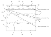
- FIG. 2 is a diagram illustrating an example of dividing a measurement target space of FIG. 1 two-dimensionally;
- FIG. 3 is a graph illustrating an example of an absorption signal with respect to a reference signal according to a wavelength of a laser beam detected by a light receiving unit according to the present invention
- FIG. 5 is a diagram illustrating an example of three-dimensional division of the measurement target space in the three-dimensional gas temperature distribution measuring method according to the present invention.
- FIG. 6 is a diagram illustrating an example in which laser light is emitted and received in a measurement target space of FIG. 5;
- FIG. 7 is a control flowchart of a three-dimensional gas temperature distribution measuring method according to the present invention.
- Measuring system 100 for performing the two-dimensional and three-dimensional gas temperature distribution measuring method according to the present invention as shown in Figure 1, the light emitting unit 110, the light receiving unit 120, the control unit 160 ).
- the light emitting unit 110 emits an optical signal to the measurement target gas in the form of a straight line, and prevents the diode laser 111 emitting the laser light and the laser light from flowing in the reverse direction.
- the main includes a first isolator 112, a coupler 113 for branching the laser light at a desired rate, and a diode laser controller 114 for adjusting the intensity and wavelength change of the laser light.
- the gas to be measured may be, for example, oxygen (O 2 ).
- the diode laser 111 is connected to the diode laser mount 116 and emits laser light according to the signal of the diode laser controller 114.
- the light emitting unit 110 is provided with a collimator (collimator).
- the collimator is a lens that allows the light transmitted along the optical cable to go straight.
- the configuration of the collimator may not be necessary. have.
- the diode laser controller 114 is operated and controlled by the controller 160 to adjust the change of the diode laser 111.
- the diode laser controller 114 may change the intensity, wavelength, frequency, and temperature of the diode laser 111 by changing the magnitudes of the temperature and the current.
- the diode laser controller 114 may be controlled independently without operation control by the controller 160 as necessary.
- the diode laser controller 114 may be used to adjust the input temperature and current of the diode laser 111 to output laser light having a desired wavelength.
- the waveform generator 115 is provided between the diode laser controller 114 and the controller 160.
- the waveform generator 115 is operated and controlled by the controller 160 so that the shape of the laser signal is transmitted in various ways. Such waveform shapes may be sawtooth waves, triangle waves, square waves, sine waves, cosine waves, or arbitrary mixed waves.
- the waveform generator 115 may be independently operated and not controlled by the controller 160 as necessary.
- the first isolator 112 and the coupler 113 are not essential and may be omitted according to circumstances.
- the light emitting unit 110 is connected to the light emission transport driver 117 which is operated and controlled by the controller 160 of the measurement target space in which the gas to be measured by the light emission transport driver 117 is present. It is preferable that the one side is provided to be capable of reciprocating vertically or vertically.
- the laser beam may be separated into several strands by the required number in the light emitting unit 110 without the configuration of the light-emitting transfer driver 117 to pass through the measurement target space.
- the oscillation path may be provided separately, but may be configured to circulate through the necessary oscillation paths at intervals of time without separation of the laser light to maintain signal strength.
- the light receiver 120 is configured to receive a laser signal received by the light emitter 110 to receive an optical signal.
- the second isolator 121 may prevent the laser light from flowing in the reverse direction.
- an optical detector 130 for receiving the optical signal, converting the optical signal into an electrical signal, and outputting the converted optical signal.
- the intensity change of the laser light is changed through the light detector 130. Can be measured.
- the intensity change of the laser beam measured as described above may be computed through the controller 160 to be described later to allow temperature measurement for each allocation section divided in the measurement target space.
- the temperature and the concentration of the measurement target gas can be simultaneously measured using one diode laser 111.
- the light receiver 120 includes a collimator, and the collimator transmits an optical signal passing through the measurement target gas to the light detector 130 through an optical cable.
- the collimator may not be necessary in systems that do not use optical cables.
- the light receiving unit 120 is connected to the light receiving driving unit 123 which is operated and controlled by the controller 160. It is preferable that the other side of the measurement target space in which the measurement target gas exists is provided to be reciprocated up and down or left and right.
- the laser beam may be separated and received by the required number from the light receiving unit 120 in accordance with the laser light oscillation conditions of the light emitting unit 110 without the configuration of the light receiving and transporting unit 123.
- the reception paths may be distinguished from each other and configured to receive an optical signal passing through a necessary oscillation path at intervals of time without separation of the laser light to maintain signal strength.
- control unit 160 includes a lock analyzer 140, an oscilloscope 150, and a data analyzer equipped with a data analysis module.
- the lock authentication width section 140 has a maximum height at the first harmonic signal or the absorption center wavelength close to the absorption signal shape through the absorption signal received from the light receiving unit 120 and the sinusoidal signal received from the waveform generator 115.
- the difference harmonic signal can be extracted.
- the lock authentication section 140 removes some noise signals.
- the oscilloscope 150 allows the signal to be output on the screen so that the signal can be easily recognized.
- the oscilloscope 150 may visually recognize a signal of the waveform generator 115, a signal of the light detector 130 of the light receiver 120, a signal of the lock authentication width 140, and the like.
- the oscilloscope 150 is intended to increase the convenience of the analyzer and is not an essential device.
- the data analysis module of the controller 160 analyzes a signal measured by direct absorption spectroscopy and stores a concentration value.
- the data analysis module is equipped with a temperature analysis module for analyzing the temperature according to the direct absorption spectroscopy, and a concentration analysis module for analyzing the concentration according to the direct absorption spectroscopy. These analysis modules can be separated in software within the same hardware.
- the controller 160 controls the operation of the diode laser controller 114 and the waveform generator 115. In this case, the controller 160 controls the generation of the waveform of the waveform generator 115 or controls the temperature / current value of the diode laser controller 114 so that the light emitter 110 emits laser light.
- the controller 160 may include an input unit 161 that receives the number of sections to be divided when virtually dividing a measurement target space, and a measurement target space. It is preferable to further include a mapping output unit 163 for displaying a two-dimensional or three-dimensional temperature distribution mapping and concentration distribution mapping of the measurement target gas.
- the controller 160 virtually divides the measurement target space 20 in which the measurement target gas exists ( S10).
- the measurement target area 20 is two-dimensionally split by a controller 160 as shown in Figure 2, is partitioned so as divided into an interval having a size such as n 2 of each other It is desirable to be.
- n is a natural number. That is, the measurement target space 20 is divided into two, four, nine, sixteen, ... by the control unit 160.
- the controller 160 can easily obtain the temperature distribution and the concentration distribution in the measurement target space 20 in two dimensions.
- any one of the n divided spaces A 1 , A 4 , A 7 located at the outermost side of the light emitting side among the two-dimensionally divided measurement target spaces in step 10. (For example, A 1 ) in a manner corresponding to 1: n toward the light receiving point 120a of each of the divided spaces A 3 , A 6 , and A 9 located at the outermost side of the light receiving side at the light emitting point 110a.
- the light emitting unit 110 emits the laser light L in the remaining areas A 4 and A 7 , respectively, and receives the light from the light receiving unit 120.
- the dimensional absorption signal (laser light intensity) is detected (S20).
- the light emitting point 110a is the position at which the light emitting unit 110 is moved or arranged so that the laser light L is oscillated, and thus the light emitting point 110a is the light emitting side of the light emitting side spaces.
- the light receiving point 120a corresponds to the center of the outermost boundary line of each of the divided spaces located outside, and the light receiving point 120a is a position where the light receiving unit 120 is moved or disposed so that the laser light L is absorbed. It is preferable to make it correspond to the center part of the outermost boundary of each division space located in the outermost side of a light receiving side among the spaces. That is, it is preferable that the laser light L is emitted and received toward the center of each of the divided spaces at the outermost side of the light receiving side from the center of each of the divided spaces at the outermost side of the light emitting side.
- the controller may be configured based on the one-dimensional absorption signal detected by the light receiver 120.
- 160 calculates the area of n 2 absorbances by direct absorption spectroscopy through the light detector 130 (S30).
- the area A S of the absorbance is the amount of light absorption loss actually generated in the measurement target space while the laser light L is emitted and received by the light receiving unit 120. As shown in FIG. 3, the reference signal according to the light wavelength is shown. The area of the difference value of the absorption signal S a with respect to S b is calculated. Therefore, the area A S of the absorbance is calculated by the controller 160 by applying the following equation through the light detector 130.
- the control unit 160 is a laser beam (for each section of the measurement target space 20 divided in two dimensions based on the calculated area of absorbance)
- the n 2 line intensity changes of L are calculated (S40).
- the line intensity change Si [T (x)] of the laser light calculated by the control unit 160 is calculated from the following functional formula.
- the pressure (P) in the measurement target space can be measured through a pressure gauge, the mole fraction (X abs ) and the line intensity change (S i [T (x)]) is unknown through a function equation. Can be.
- the line intensity change Si [T (x)] is a function of temperature only, the temperature T can be obtained if this value is known.
- the length l i through which the laser beam passes is determined by the controller 160 in a geometric manner. Can be. If the total length of the two-dimensional horizontal sides of the measurement target space 20 is 12 m, l 6 is 4 m divided by 12 m by 3.
- the controller 160 controls the light detector 130.
- nine linear first-order polynomial equations respectively corresponding to the divided number of spaces can be generated from the equation (2).
- a S1 PS 1 (T 1 ) X 1 l 1 + PS 1 (T 4 ) X 4 l 2 + PS 1 (T 5 ) X 5 l 3 + PS 1 (T 6 ) X 6 l 2 + PS 1 ( T 9 ) X 9 l 1
- a S2 PS 1 (T 1 ) X 1 l 4 + PS 1 (T 2 ) X 2 l 5 + PS 1 (T 5 ) X 5 l 5 + PS 1 (T 6 ) X 6 l 4
- a S3 PS 1 (T 1 ) X 1 l 6 + PS 1 (T 2 ) X 2 l 6 + PS 1 (T 3 ) X 3 l 6
- a S4 PS 1 (T 4 ) X 4 l 4 + PS 1 (T 5 ) X 5 l 5 + PS 1 (T 8 ) X 8 l 5 + PS 1 (T 9 ) X 9 l 4
- a S5 PS 1 (T 4 ) X 4 l 6 + PS 1 (T 5 ) X 5 l 6 + PS 1 (T 6 ) X 6 l 6
- a S6 PS 1 (T 4 ) X 4 l 4 + PS 1 (T 5 ) X 5 l 5 + PS 1 (T 2 ) X 2 l 5 + PS 1 (T 3 ) X 3 l 4
- a S7 PS 1 (T 7 ) X 7 l 6 + PS 1 (T 8 ) X 8 l 6 + PS 1 (T 9 ) X 9 l 6
- a S8 PS 1 (T 7 ) X 7 l 4 + PS 1 (T 8 ) X 8 l 5 + PS 1 (T 5 ) X 5 l 5 + PS 1 (T 6 ) X 6 l 4
- a S9 PS 1 (T 7 ) X 7 l 1 + PS 1 (T 4 ) X 4 l 2 + PS 1 (T 5 ) X 5 l 3 + PS 1 (T 6 ) X 6 l 2 + PS 1 ( T 3 ) X 3 l 1
- the laser light emitted and received in step 20 is a wavelength tunable laser light so that two laser light beams having different wavelength bands can be simultaneously emitted and received, or two laser light beams having different wavelength bands can be used. It may be made to emit and receive separately.
- control unit 160 performs the process of calculating the line intensity change through Equation 2 from the one-dimensional absorption signal of another wavelength by performing steps 20 to 40 again through light emission and reception of laser light of another wavelength.
- the two-dimensional temperature distribution of the measurement target space 20 is mapped by calculating the temperature for each section of the divided measurement object space 20 from the following function equation (S50).
- control unit 160 can calculate the temperature and the position of each temperature in real time for each section of the measurement target space 20 divided into two dimensions through Equation 3 in step 50, so that the temperature distribution is previewed. Instead of making predictions, the actual measurement target space is measured one-dimensionally with a diode laser to grasp the two-dimensional temperature distribution of the gas to be measured, thereby minimizing the error of the measurement and thus allowing accurate measurement to be performed.
- control unit 160 calculates the mole fraction of the measurement target gas for each section of the two-dimensionally divided measurement target space 20 by two-dimensional Map the concentration distribution (S60).
- the controller 160 divides two-dimensionally by obtaining the mole fraction X i by substituting the temperature obtained in the solution of each line intensity change S i (T i ) X i when the temperature is found in step 50.
- Each concentration and the position of the concentration for each section of the measured measurement target space 20 can be calculated in real time.
- step 50 when the temperature is obtained in step 50, the value of S 1 (T i ) and the value of S 2 (T i ) are determined, so that the controller 160 can obtain the value of the mole fraction X i by the following equation. .
- the temperature and concentration distribution of gas in a space where two-dimensional measurement is impossible by measuring only one-dimensional by using a diode laser, making it difficult to make two-dimensional measurement without restriction of measurement space.
- the temperature and concentration distribution of the gas can be easily measured even in a structure such as a heating furnace, and the temperature distribution and the position of the concentration distribution of the gas to be measured in the measurement target space 20 can be accurately identified in two dimensions. have.
- the three-dimensional gas temperature distribution measuring method according to the present invention extends the two-dimensional gas temperature distribution measuring method, and as shown in FIGS. 5 and 6, temperature and concentration in three dimensions through one-dimensional measurement.
- a method for measuring a three-dimensional gas temperature distribution according to the present invention will be described with reference to FIGS. 5 to 7.
- the controller 160 virtually divides the measurement target space 20 in which the measurement target gas exists ( S100).
- the measurement target space 20 divided three-dimensionally by the controller 160 is divided to be divided into sections having n 3 mutually equal volumes. It is desirable to be. Where n is a natural number. That is, the measurement target space 20 is divided three-dimensionally, such as eight, 27, 64 ... by the control unit 160.
- the number of unknowns (T i , X i ) in Equation 2 for obtaining the area of absorbance is equal to the number of area calculations of absorbance.
- the temperature distribution and the concentration distribution in the object space 20 can be easily obtained in three dimensions.
- n 2 partition spaces A 1 , located at the outermost side of the light emitting side among the three-dimensionally divided measurement target spaces in step 10.
- the light emitting unit 110 is also included in the remaining areas A 1 , A 3 , A 10 , A 11 , A 12 , A 19 , A 20 , and A 21 for each divided n 2 spatial sections corresponding to the light emitting side.
- the laser beam L is emitted and received by the light receiving unit 120 to detect a
- the light emitting point 110a is a position at which the light emitting unit 110 is moved or arranged so that the laser light L is oscillated, and thus the light emitting side 110a is the maximum of the light emitting side.
- the light receiving point 120a corresponds to the center of the outermost boundary surface of each of the divided spaces located outside, and the light receiving point 120a is a position where the light receiving unit 120 is moved or disposed to absorb the laser light L. It is preferable to make it correspond to the center part of the outermost boundary surface of each division space located in the outermost side of a light receiving side among the spaces. That is, it is preferable that the laser light L is emitted and received toward the center of each of the divided spaces at the outermost side of the light receiving side from the center of each of the divided spaces at the outermost side of the light emitting side.
- the controller may be configured based on the one-dimensional absorption signal detected by the light receiver 120.
- 160 calculates the area of n 3 absorbances by direct absorption spectroscopy through the light detector 130 (S300).
- the controller 160 controls the laser light L for each section of the measurement target space 20 which is three-dimensionally divided based on the calculated area of the absorbance. Calculate a change in the n 3 line intensity of (S400).
- the line intensity change Si [T (x)] of the laser light calculated by the controller 160 is the same as that of the two-dimensional gas temperature distribution measuring method. It is preferable to calculate from Equation 2.
- n the presented corresponding to the divided space control unit 160 of the measurement target area 20 is divided into a three-dimensional three generates a n 3 of the equation, and as shown in FIG. 6, each of the divided
- n 3 of the equation As shown in FIG. 6, each of the divided
- the controller 160 divides the space through the light detector 130. 27 linear first-order polynomial equations corresponding to the numbers may be generated from Equation 2 above.
- the laser light emitted and received in step 200 may be a tunable laser light so that two laser lights having different wavelength bands may be simultaneously emitted and received, or two laser lights having different wavelength bands may be used. It may be made to emit and receive separately.
- control unit 160 performs the processing of the line intensity change through Equation 2 from the one-dimensional absorption signal of another wavelength by re-executing from step 200 to step 400 through light emission and light reception of laser light of another wavelength.
- the temperature for each section of the divided measurement target space 20 is calculated from Equation 3 to map the three-dimensional temperature distribution of the measurement target space 20 (S500).
- control unit 160 can calculate the temperature and the position of each temperature in real time for each section of the measurement target space 20 divided three-dimensionally through Equation 3 in step 500, so that the temperature distribution Instead of predicting in advance, the actual measurement target space is measured one-dimensionally with a diode laser to grasp the three-dimensional temperature distribution of the measurement target gas, thereby minimizing the error of the measurement so that accurate measurement can be performed.
- control unit 160 calculates the mole fraction of the measurement target gas for each section of the three-dimensionally divided measurement target space 20 to map the three-dimensional concentration distribution (S600).
- the controller 160 divides the three-dimensionally by obtaining the mole fraction X i by substituting the temperature obtained in the solution of the respective line intensity change S i (T i ) X i when the temperature is obtained in step 500.
- each concentration and the position of the concentration can be calculated in real time.
- the temperature and concentration distribution of the gas in the space where two-dimensional or three-dimensional measurement is impossible can be measured in one dimension only by using a diode laser to map two-dimensionally or three-dimensionally, thereby measuring the measurement space. It is possible to easily measure the temperature and concentration distribution of gas even in structures such as heating furnaces in steelworks, where it is difficult to make two-dimensional or three-dimensional measurements without restriction. Can be accurately identified in two or three dimensions.
Landscapes
- Physics & Mathematics (AREA)
- Spectroscopy & Molecular Physics (AREA)
- General Physics & Mathematics (AREA)
- Investigating Or Analysing Materials By Optical Means (AREA)
- Measuring Temperature Or Quantity Of Heat (AREA)
Abstract
본 발명은 2차원 및 3차원적 가스 온도 분포 측정 방법에 관한 것으로, 다이오드 레이저를 이용하여 1차원적으로만 측정하여 2차원 또는 3차원 측정이 불가능한 공간 내의 가스의 온도 및 농도 분포를 2차원 또는 3차원적으로 매핑하는 것을 특징으로 한다. 이에 의하여, 측정 공간의 제약이 없이 2차원 또는 3차원 측정이 어려운 제철소의 가열로와 같은 구조물 내에서도 가스의 온도 및 농도 분포를 2차원 또는 3차원적으로 용이하게 측정할 수 있다.
Description
본 발명은 2차원 및 3차원적 가스 온도 분포 측정 방법에 관한 것으로, 더욱 상세하게는 2차원 또는 3차원적 측정이 어려운 제철소의 가열로와 같은 구조물 내에서의 가스의 온도 분포를 측정하도록 방법을 개선한 2차원 및 3차원적 가스 온도 분포 측정 방법에 관한 것이다.
일반적으로 제철소의 가열로와 같은 구조물 내에서의 가스 온도 측정은 가열로 내에 설치된 온도측정장치에 의해 이루어지게 된다.
이러한 온도 측정 방법의 일 예가 대한민국 특허공개번호 제10-2005-0095159호(2005년09월29일자 공개, 이하 '특허문헌 1'이라 함) 등에 개시되어 있다.
그러나, 이러한 종래기술에 따른 온도 측정 방법으로는 온도측정장치가 설치되는 위치가 가열로의 벽체에 한정되어 설치된 위치에서만 온도를 측정하기 때문에 가열로 내부 전체에서의 가스의 온도 분포와 농도 분포는 측정이 불가능해질 수 있다는 문제점이 있다.
이러한 문제점을 해결하고자 최근 들어서는 다이오드 레이저를 이용한 온도 측정 방법이 도입되고 있는 실정이다.
그러나, 종래의 다이오드 레이저를 이용한 온도 측정 방법은 대부분이 선적분 계측 방식으로서 다이오드 레이저가 지나간 길이의 평균 온도만을 측정하게 되는 한계를 지니고 있다.
이러한 한계를 극복하고자 최근에는 단면상 온도예측(profile fitting) 방법과 온도 분할(temperature binning) 방법이 도입되고 있다.
그러나, 단면상 온도예측 방법은 일정 공간 내에서의 가스의 온도 분포를 미리 예측하여 측정 변수를 줄여주기 위한 것으로서, 예를 들면 파이프 내부를 통해 고온의 기체가 흐를 경우 파이프 중심에서의 온도가 가장 높고 파이프 가장자리에서는 열전달에 의해 온도가 상대적으로 낮아지는 포물선 형태의 온도 분포를 갖는다는 가정하에 이루어지게 된다. 이는 측정 변수를 줄이며 측정 시스템을 간소화할 수 있지만, 그만큼 측정치와 실제 가스의 온도 분포 간에 차이가 크기 때문에 측정의 오차가 커지게 되어 정확한 측정을 기대할 수 없다는 문제점이 있다.
한편, 온도 분할 방법은 측정 온도 구간을 미리 예측하고 그 온도 구간을 임의로 나누어 측정 변수를 줄이며 측정 시스템을 간소화하기 위한 것으로서, 이는 다이오드 레이저가 지나가는 선에서의 선 온도 분포를 예측할 수 있게 하지만, 2차원적 온도 분포를 알기 위해서는 2차원 각각의 방향으로 온도를 측정해야 하기 때문에 제철소의 가열로와 같은 구조물 내에서는 2차원적 온도 분포의 측정이 불가능해질 수 있다는 문제점이 있다.
또한, 종래의 온도 분할 방법에 의한 온도 측정 방법은 온도 구간별로 온도가 측정되더라도 측정된 온도의 위치를 특정할 수 없기 때문에 온도의 분포 상태를 파악하기가 어려워질 수 있다는 문제점이 있다.
본 발명의 목적은, 측정의 오차가 최소화되어 정확한 측정이 수행될 수 있는 2차원 및 3차원적 가스 온도 분포 측정 방법을 제공하는 것이다.
또한, 측정 공간의 제약이 없이 2차원 또는 3차원적 측정이 어려운 제철소의 가열로와 같은 구조물 내에서도 가스의 온도 분포를 측정할 수 있는 2차원 및 3차원적 가스 온도 분포 측정 방법을 제공하는 것이다.
아울러, 측정대상공간 내에서 측정대상가스의 온도 분포 및 농도 분포의 위치가 정확히 파악될 수 있는 2차원 및 3차원적 가스 온도 분포 측정 방법을 제공하는 것이다.
상기 목적을 달성하기 위해 본 발명에 따른 2차원적 가스 온도 분포 측정 방법은: (a) 측정대상공간을 제어부가 2차원적으로 분할하되, 2차원적으로 분할된 공간이 n2개의 상호 등면적을 갖도록 분할하는 단계; (b) 상기 분할된 측정대상공간들 중 발광 측 최외곽에 위치된 분할 공간들(A1, A4, A7)의 발광점에서 수광 측 최외곽에 위치된 분할 공간들(A3, A6, A9)의 수광점을 향해 1:n으로 대응되게 레이저광을 발광시켜 수광부에서 흡수신호를 검출하는 단계; (c) 상기 수광부에서 검출된 흡수신호에 기초하여 제어부가 직접 흡수 분광 기법으로 n2개의 흡광도의 넓이를 연산하는 단계; (d) 상기 연산된 흡광도의 넓이에 기초하여 제어부가 분할된 측정대상공간의 구간별로 레이저광의 n2개의 제1 선 강도 변화(ai=S1(Ti)Xi)를,

(Asi: 광 투과 경로별 흡광도의 넓이, P: 측정대상공간 내에서의 압력, Xabs: 몰분율)
의 함수식으로부터 연산하는 단계; 및, (e) 상기 제1 선 강도 변화(ai=S1(Ti)Xi)와, (a) 단계부터 (d) 단계까지 수행하여 연산 처리된 다른 파장 대역의 제2 선 강도 변화(bi=S2(Ti)Xi)를 가지고 제어부가 상기 분할된 측정대상공간의 구간별 온도를,

의 함수식으로부터 산출하여 상기 측정대상공간의 2차원적 온도 분포를 매핑(mapping)하는 단계;를 포함하는 것을 특징으로 한다.
여기서, 본 발명에 따른 2차원적 가스 온도 분포 측정 방법은 (f) 상기 매핑된 2차원적 온도 분포에 기초하여 제어부가 상기 분할된 측정대상공간의 구간별 측정대상가스의 몰분율(mole fraction)을 산출하여 2차원적 농도 분포를 매핑하는 단계를 더 포함하는 것이 바람직하다.
한편, 상기 목적을 달성하기 위해 본 발명에 따른 3차원적 가스 온도 분포 측정 방법은: (a´) 측정대상공간을 제어부가 3차원적으로 분할하되, 3차원적으로 분할된 공간이 n3개의 상호 등체적을 갖도록 분할하는 단계; (b´) 상기 분할된 측정대상공간들 중 발광 측 최외곽에 위치된 분할 공간들(A1, A2, A3, A10, A11, A12, A19, A20, A21)의 발광점에서 수광 측 최외곽에 위치된 분할 공간들(A7, A8, A9, A16, A17, A18, A25, A26, A27) 중 동일 높이에 있는 n개의 수광점을 향해 1:n으로 대응되게 레이저광을 발광시켜 수광부에서 흡수신호를 검출하는 단계; (c´) 상기 수광부에서 검출된 흡수신호에 기초하여 제어부가 직접 흡수 분광 기법으로 n3개의 흡광도의 넓이를 연산하는 단계; (d´) 상기 연산된 흡광도의 넓이에 기초하여 제어부가 분할된 측정대상공간의 구간별로 레이저광의 n3개의 제1 선 강도 변화(ai=S1(Ti)Xi)를,

(Asi: 광 투과 경로별 흡광도의 넓이, P: 측정대상공간 내에서의 압력, Xabs: 몰분율)
의 함수식으로부터 연산하는 단계; 및, (e´) 상기 제1 선 강도 변화(ai=S1(Ti)Xi)와, (a´) 단계부터 (d´) 단계까지 수행하여 연산 처리된 다른 파장 대역의 제2 선 강도 변화(bi=S2(Ti)Xi)를 가지고 제어부가 상기 분할된 측정대상공간의 구간별 온도를,

의 함수식으로부터 산출하여 상기 측정대상공간의 3차원적 온도 분포를 매핑하는 단계;를 포함하는 것을 특징으로 한다.
여기서, 본 발명에 따른 3차원적 가스 온도 분포 측정 방법은 (f´) 상기 매핑된 3차원적 온도 분포에 기초하여 제어부가 상기 분할된 측정대상공간의 구간별 측정대상가스의 몰분율을 산출하여 3차원적 농도 분포를 매핑하는 단계를 더 포함하는 것이 바람직하다.
본 발명에 따르면, 온도 분포를 미리 예측하는 것이 아니라 실제 측정대상공간을 다이오드 레이저로 1차원적으로 측정하여 측정대상가스의 2차원 또는 3차원적인 온도 분포 및 농도 분포를 파악하도록 함으로써 측정의 오차가 최소화되어 정확한 측정이 수행되도록 할 수 있다.
또한, 다이오드 레이저를 이용하여 1차원적으로만 측정하여 2차원 또는 3차원 측정이 불가능한 공간 내의 가스의 온도분포를 2차원 또는 3차원적으로 매핑 할 수 있게 됨으로써 측정 공간의 제약이 없이 2차원 또는 3차원적 측정이 어려운 제철소의 가열로와 같은 구조물 내에서도 가스의 온도 및 농도 분포를 용이하게 측정할 수 있다.
아울러, 측정대상공간 내에서 측정대상가스의 온도 분포 및 농도 분포의 위치가 2차원 또는 3차원적으로 정확히 파악되도록 할 수 있다.
도 1은 본 발명에 따른 2차원 및 3차원적 가스 온도 분포 측정 방법을 수행하기 위한 측정 시스템의 제어 블록도,
도 2는 도 1의 측정대상공간을 2차원적으로 분할하는 일 예를 도시한 도면,
도 3은 본 발명에 따라 수광부에서 검출되는 레이저광의 파장에 따른 기준신호에 대한 흡수신호의 일 예를 나타낸 그래프,
도 4는 본 발명에 따른 2차원적 가스 온도 분포 측정 방법의 제어 흐름도,
도 5는 본 발명에 따른 3차원적 가스 온도 분포 측정 방법에서 측정대상공간을 3차원적으로 분할하는 일 예를 도시한 도면,
도 6은 도 5의 측정대상공간에서 레이저광이 발광 및 수광되는 일 예를 도시한 도면,
도 7은 본 발명에 따른 3차원적 가스 온도 분포 측정 방법의 제어 흐름도이다.
(도면 부호의 설명)
110 : 발광부 120 : 수광부
130 : 광 검출부 160 : 제어부
이하에서는 첨부된 도면을 참조하여 본 발명에 대해 상세히 설명한다.
본 발명에 따른 2차원 및 3차원적 가스 온도 분포 측정 방법을 수행하기 위한 측정 시스템(100)은, 도 1에 도시된 바와 같이, 발광부(110)와, 수광부(120)와, 제어부(160)를 포함한다.
발광부(110)는, 도 1에 도시된 바와 같이, 광신호를 직진의 형태로 측정대상가스에 발광하는 것으로서, 레이저광을 발광하는 다이오드 레이저(111)와, 레이저광이 역방향으로 흐르는 것을 막아주는 제1 아이솔레이터(112)와, 레이저광을 원하는 비율로 분기하는 커플러(113)와, 레이저광의 강도 및 파장 변화를 조절하는 다이오드레이저 컨트롤러(114)를 갖춘다.
측정대상가스는 일 예로 산소(O2)가 될 수 있다.
다이오드 레이저(111)는 다이오드레이저 마운트(116)에 연결되어 있으며, 다이오드레이저 컨트롤러(114)의 신호에 따라 레이저광을 발광한다.
발광부(110)에는 콜리메이터(collimator)가 구비된다. 이때 콜리메이터는 광학 케이블을 따라 전달된 빛이 직진할 수 있도록 하는 렌즈로서, 발광부(110)는 광케이블을 통과하지 않고 다이오드 레이저(111)에서 레이저가 직접 발광할 경우, 콜리메이터의 구성이 필요치 않을 수도 있다.
다이오드레이저 컨트롤러(114)는 제어부(160)에 의해 작동제어되어, 다이오드 레이저(111)의 변화를 조절한다. 이때, 다이오드레이저 컨트롤러(114)는 온도와 전류의 크기를 변화시킴으로써 다이오드 레이저(111)의 강도 및 파장, 주파수, 온도를 변화시킬 수 있다. 한편, 다이오드레이저 컨트롤러(114)는 필요에 따라서는 제어부(160)에 의해 작동제어되지 않고 독립적으로 작동제어될 수도 있다.
이에 따라, 다이오드레이저 컨트롤러(114)를 이용하여 다이오드 레이저(111)의 입력 온도와 전류를 조절하여 원하는 파장의 레이저광을 출력시킬 수 있다.
한편, 다이오드레이저 컨트롤러(114)와 제어부(160)의 사이에는 파형발생부(115)가 구비된다.
파형발생부(115)는 제어부(160)에 의해 작동제어되어, 레이저 신호의 모양이 다양하게 송출되도록 한다. 이러한 파형 모양으로는 톱니파, 삼각파, 사각파, 사인파, 코사인파 또는 임의의 혼합파 등이 될 수 있다. 파형발생부(115)는 필요에 따라서는 제어부(160)에 의해 작동제어되지 않고 독립적으로 작동제어될 수도 있다.
한편, 제1 아이솔레이터(112) 및 커플러(113)는 필수적인 것은 아니며, 상황에 따라 생략될 수도 있다.
본 발명의 일실시예로서, 발광부(110)는 제어부(160)에 의해 작동제어되는 발광 이송구동부(117)에 연결되어 발광 이송구동부(117)에 의해 측정대상가스가 존재하는 측정대상공간의 일측에서 상하 또는 좌우로 왕복 이송 가능하게 구비된 것이 바람직하다.
한편, 또 다른 예로서, 발광 이송구동부(117)의 구성없이 레이저광을 발광부(110)에서 필요한 숫자만큼 여러 가닥으로 분리하여 측정대상공간을 지나도록 할 수 있다. 또는 발진 경로는 구별하여 구비하되, 신호강도 유지를 위해 레이저광의 분리없이 시간의 간격을 두고 필요한 발진 경로를 순환하여 지나도록 구성할 수도 있다.
수광부(120)는, 도 1에 도시된 바와 같이, 발광부(110)에서 발광된 레이저광을 수광하여 광신호를 수신하도록 구비된 것으로서, 레이저광이 역방향으로 흐르는 것을 막아주는 제2 아이솔레이터(121)와, 광신호를 수신하고 전기적인 신호로 변환하여 출력하는 광 검출부(130)를 갖춘다.
이에 따라, 다이오드 레이저(111)에서 출력된 레이저광이 발광부(110)에서 발광되어 측정대상공간을 통과하여 수광부(120)를 통해 수광된 후, 광 검출부(130)를 통해 레이저광의 강도 변화가 측정될 수 있다. 이렇게 측정된 레이저광의 강도 변화는 후술할 제어부(160)를 통해 연산 처리되어 측정대상공간 내에서 분할된 할당 구간별로 온도 측정이 가능해지도록 할 수 있다.
즉, 본 발명에 따르면 하나의 다이오드 레이저(111)를 이용하여 측정대상가스의 온도와 농도를 동시에 계측할 수 있다.
수광부(120)는 콜리메이터를 구비하며, 콜리메이터는 측정대상가스를 지나온 광 신호를 광학 케이블를 통해 광 검출부(130)에 전달한다. 이때 콜리메이터는 광학 케이블을 사용하지 않는 시스템에서는 필요하지 않을 수도 있다.
본 발명의 일실시예로서, 도 1 및 도 2에 도시된 바와 같이, 수광부(120)는 제어부(160)에 의해 작동제어되는 수광 이송구동부(123)에 연결되어 수광 이송구동부(123)에 의해 측정대상가스가 존재하는 측정대상공간의 타측에서 상하 또는 좌우로 왕복 이송 가능하게 구비된 것이 바람직하다.
한편, 또 다른 예로서, 발광부(110)의 레이저광 발진 조건에 맞추어 수광 이송구동부(123)의 구성없이 레이저광을 수광부(120)에서 필요한 숫자만큼 분리하여 수신하도록 할 수 있다. 또는 수신 경로를 구별하여 구비하여 신호강도 유지를 위해 레이저광의 분리없이 시간의 간격을 두고 필요한 발진 경로를 순환하여 지나온 광신호를 수신하도록 구성할 수도 있다.
제어부(160)는, 도 1에 도시된 바와 같이, 락인증폭부(140)와, 오실로스코프(150)와, 데이터분석모듈을 갖춘 데이터분석기를 포함한다.
락인증폭부(140)는 수광부(120)로부터 수신한 흡수신호와 파형발생부(115)로부터 수신한 정현파의 신호를 통해 흡수신호 모양과 가까운 1차 조화신호 또는 흡수 중심 파장에서 최고 높이를 갖는 2차 조화신호를 추출할 수 있다. 또한 락인증폭부(140)는 일부 노이즈 신호를 제거한다.
오실로스코프(150)는 신호를 쉽게 인지할 수 있도록 화면에 출력할 수 있게 한다. 또한, 오실로스코프(150)는, 파형발생부(115)의 신호, 수광부(120)의 광 검출부(130)의 신호, 락인증폭부(140)의 신호 등을 육안으로 인지할 수 있게 한다. 오실로스코프(150)는 분석자의 편리성 증대를 위한 것으로 필수적인 장치는 아니다.
제어부(160)의 데이터분석모듈은 직접 흡수 분광 기법에 의해 측정된 신호를 분석하고 농도 값을 저장한다. 이때, 데이터분석모듈은 직접 흡수 분광 기법에 따라 온도를 분석하는 온도분석모듈과, 직접 흡수 분광 기법에 따라 농도를 분석하는 농도분석모듈을 갖춘다. 이러한 분석모듈은 동일한 하드웨어 내에서 소프트웨어적으로 분리할 수 있다.
제어부(160)는 다이오드레이저 컨트롤러(114) 및 파형발생부(115)를 작동제어한다. 이때, 제어부(160)는 파형발생부(115)의 파형발생을 제어하거나, 다이오드레이저 컨트롤러(114)의 온도/전류값을 제어하여, 발광부(110)가 레이저광을 발광하도록 한다.
한편, 본 발명의 일실시예로서, 제어부(160)는, 도 1에 도시된 바와 같이, 측정대상공간을 가상적으로 분할할 때에 분할되는 구간의 개수를 입력받는 입력부(161)와, 측정대상공간에서 측정대상가스의 2차원 또는 3차원적 온도 분포 매핑(mapping)과 농도 분포 매핑을 디스플레이하는 매핑 출력부(163)를 더 포함하는 것이 바람직하다.
이러한 구성에 의해, 본 발명에 따른 2차원적 가스 온도 분포 측정 방법을 도 1 내지 도 4를 참조하여 설명하면 다음과 같다.
우선, 2차원적으로 분할되는 측정대상공간(20)의 구간 개수가 입력부(161)를 통해 입력되면, 측정대상가스가 존재하는 측정대상공간(20)을 제어부(160)가 가상적으로 분할한다(S10).
이때, 본 발명의 일실시예로서, 도 2에 도시된 바와 같이, 제어부(160)에 의해 2차원적으로 분할되는 측정대상공간(20)은 n2개의 상호 등면적을 갖는 구간으로 나누어지도록 분할되는 것이 바람직하다. 여기서, n은 자연수이다. 즉, 측정대상공간(20)은 제어부(160)에 의해 4개, 9개, 16개...등과 같이 2차원적으로 분할된다.
이에 따라, 도 2에 도시된 바와 같이, 후술할 흡광도의 넓이를 구하는 수학식 2에서의 미지수(Ti, Xi)의 개수와 흡광도의 넓이 연산 개수가 같아지게 되어 미지수의 개수와 방정식의 개수가 같아지게 됨으로써 제어부(160)가 측정대상공간(20) 내에서의 온도 분포와 농도 분포를 2차원적으로 용이하게 구할 수 있다.
본 발명의 일실시예로서, 도 2에 도시된 바와 같이, 측정대상공간(20)은 제어부(160)에 의해 32= 9개로 2차원적으로 분할되어 9개의 상호 등면적을 갖는 구간으로 나누어진 것으로 한다.
다음에, 단계 10에서 2차원적으로 분할된 측정대상공간들 중 발광 측 최외곽에 위치된 n개(예컨대, n=3)의 분할 공간들(A1, A4, A7)중 어느 하나(예컨대, A1)의 발광점(110a)에서 수광 측 최외곽에 위치된 각각의 분할 공간(A3, A6, A9)의 수광점(120a)을 향해 1:n으로 대응되는 방식으로 발광 측에 해당하는 각각의 분할된 n개의 공간 구간별로 나머지 영역(A4, A7)에서도 각각 발광부(110)에서 레이저광(L)을 발광시켜 수광부(120)에서 수광하여 직선 형태의 1차원적 흡수신호(레이저광의 세기)를 검출한다(S20).
이때, 본 발명의 일실시예로서, 발광점(110a)은 발광부(110)가 이동 또는 배치되어 레이저광(L)이 발진되는 위치로서 2차원적으로 분할된 측정대상공간들 중 발광 측 최외곽에 위치된 각 분할 공간들의 최외곽 경계선의 중심부에 해당되고, 수광점(120a)은 수광부(120)가 이동 또는 배치되어 레이저광(L)이 흡수되는 위치로서 2차원적으로 분할된 측정대상공간들 중 수광 측 최외곽에 위치된 각 분할 공간들의 최외곽 경계선의 중심부에 해당되도록 하는 것이 바람직하다. 즉, 레이저광(L)은 발광 측 최외곽의 각 분할 공간들의 중심에서 수광 측 최외곽의 각 분할 공간들의 중심을 향해 발광되고 수광되도록 하는 것이 바람직하다.
단계 20에서 발광부(110)에서 발광된 레이저광(L)을 수광부(120)에서 수광하여 1차원적 흡수신호를 검출하면, 수광부(120)에서 검출된 1차원적 흡수신호에 기초하여 제어부(160)는 광 검출부(130)를 통해 직접 흡수 분광 기법으로 n2개의 흡광도의 넓이를 연산한다(S30).
흡광도의 넓이(AS)는 레이저광(L)이 발광되어 수광부(120)에서 수광되는 동안 측정대상공간에서 실제 발생된 광 흡수 손실량으로서, 도 3에 도시된 바와 같이, 광 파장에 따른 기준신호(Sb)에 대한 흡수신호(Sa)의 차이 값의 면적으로 연산된다. 따라서, 흡광도의 넓이(AS)는 제어부(160)가 광 검출부(130)를 통해 다음의 수학식을 적용하여 산출하게 된다.
(수학식 1)

(AS: 흡광도의 넓이, Sa: 흡수신호, Sb: 기준신호, ν: 파장)
한편, 단계 30에서 광 검출부(130)를 통해 흡광도의 넓이가 연산되면, 제어부(160)는 연산된 흡광도의 넓이에 기초하여 2차원적으로 분할된 측정대상공간(20)의 구간별로 레이저광(L)의 n2개의 선 강도 변화를 연산한다(S40).
본 발명의 일실시예로서, 제어부(160)가 연산하는 레이저광의 선 강도 변화(Si[T(x)])는, 다음의 함수식으로부터 연산되는 것이 바람직하다.
(수학식 2)

(Asi: 광 투과 경로별 흡광도의 넓이, P: 측정대상공간 내에서의 압력, Xabs: 몰분율)
이때, 측정대상공간 내에서의 압력(P)는 압력계를 통해 측정될 수 있고, 몰분율(Xabs)와, 선 강도 변화(Si[T(x)])는 미지수로서 함수 식을 통해 구해질 수 있다. 특히, 선 강도 변화(Si[T(x)])는 온도만의 함수이므로 이 값을 알게 된다면 온도(T)를 구할 수 있다.
예를 들어, 도 2에 도시된 바와 같이, 측정대상공간(20)을 2차원적으로 9개의 구간으로 나눈 경우 레이저광이 지나가는 길이(li)는 기하학적 방법으로 제어부(160)에 의해 구해질 수 있다. 측정대상공간(20)의 2차원적 가로변 전체의 길이가 12 m라고 한다면, l6는 12 m를 3으로 나눈 4 m가 된다.
도 2에 도시된 바와 같이, 수광부(120)를 향해 1:n 대응되게 각각의 방향으로 레이저광(L)이 발광되어 수광부(120)에서 수광되면, 제어부(160)는 광 검출부(130)를 통해 분할된 공간 개수에 각각 대응되는 다음의 9개의 선형 1차 다원 방정식을 상기 수학식 2로부터 생성시킬 수 있다.
AS1= PS1(T1)X1l1+ PS1(T4)X4l2+ PS1(T5)X5l3+ PS1(T6)X6l2+ PS1(T9)X9l1
AS2= PS1(T1)X1l4+ PS1(T2)X2l5+ PS1(T5)X5l5+ PS1(T6)X6l4
AS3= PS1(T1)X1l6+ PS1(T2)X2l6+ PS1(T3)X3l6
AS4= PS1(T4)X4l4+ PS1(T5)X5l5+ PS1(T8)X8l5+ PS1(T9)X9l4
AS5= PS1(T4)X4l6+ PS1(T5)X5l6+ PS1(T6)X6l6
AS6= PS1(T4)X4l4+ PS1(T5)X5l5+ PS1(T2)X2l5+ PS1(T3)X3l4
AS7= PS1(T7)X7l6+ PS1(T8)X8l6+ PS1(T9)X9l6
AS8= PS1(T7)X7l4+ PS1(T8)X8l5+ PS1(T5)X5l5+ PS1(T6)X6l4
AS9= PS1(T7)X7l1+ PS1(T4)X4l2+ PS1(T5)X5l3+ PS1(T6)X6l2 + PS1(T3)X3l1
제어부(160)는 상기 방정식을 연산하여 n2개의 제1 선 강도 변화(ai=S1(Ti)Xi)를 구할 수 있으며, 그 해는 다음과 같이 표현될 수 있다.
S1(T1)X1 = a1, S1(T2)X2 = a2.....S1(T9)X9 = a9
이때, 온도(Ti)를 구하기 위해서는 또 다른 파장의 흡수신호가 필요하다.
이를 위하여, 단계 20에서 발광되고 수광되는 레이저광은 파장 가변형 레이저광이 되도록 하여 파장 대역이 서로 상이한 두 개의 레이저광이 동시에 발광 및 수광되도록 하거나 서로 상이한 파장 대역을 갖는 두 가지의 레이저광이 각각 한 번씩 따로 발광 및 수광되게 할 수도 있다.
좀더 구체적으로, 제어부(160)는 또 다른 파장의 레이저광의 발광 및 수광을 통해 단계 20부터 단계 40까지 재수행하여 또 다른 파장의 1차원적 흡수신호로부터 상기 수학식 2를 통해 선 강도 변화를 연산 처리하여 또 다른 파장 대역의 제2 선 강도 변화(bi=S2(Ti)Xi)를 구하게 되는데, 그 해는 다음과 같이 표현될 수 있다.
S2(T1)X1 = b1, S2(T2)X2 = b2.....S2(T9)X9 = b9
즉, 제어부(160)는 제1 선 강도 변화(ai=S1(Ti)Xi)와 제2 선 강도 변화(bi=S2(Ti)Xi)를 가지고 2차원적으로 분할된 측정대상공간(20)의 구간별 온도를 다음의 함수식으로부터 산출하여 측정대상공간(20)의 2차원적 온도 분포를 매핑(mapping)한다(S50).
(수학식 3)

이에 따라, 제어부(160)가 단계 50에서 수학식 3을 통하여 2차원적으로 분할된 측정대상공간(20)의 구간별로 각각의 온도와 온도의 위치를 실시간으로 산출해낼 수 있게 되므로 온도 분포를 미리 예측하는 것이 아니라 실제 측정대상공간을 다이오드 레이저로 1차원적으로 측정하여 측정대상가스의 2차원적인 온도 분포를 파악하도록 함으로써 측정의 오차가 최소화되어 정확한 측정이 수행되도록 할 수 있다.
그리고, 단계 50에서 매핑된 2차원적 온도 분포에 기초하여 제어부(160)는 2차원적으로 분할된 측정대상공간(20)의 구간별로 측정대상가스의 몰분율(mole fraction)을 산출하여 2차원적 농도 분포를 매핑한다(S60).
즉, 제어부(160)는 단계 50에서 온도가 구해지면 각각의 선 강도 변화(Si(Ti)Xi)의 해에 구해진 온도를 대입하여 몰분율(Xi)을 구함으로써 2차원적으로 분할된 측정대상공간(20)의 구간별로 각각의 농도와 농도의 위치를 실시간으로 산출해낼 수 있다.
예컨대, 단계 50에서 온도가 구해지면 S1(Ti)의 값과 S2(Ti)의 값이 정해지므로 제어부(160)는 다음의 식에 의해 몰분율(Xi)의 값을 구할 수 있다.
Xi=ai/S1(Ti) or Xi=bi/S2(Ti)
이에 따라, 다이오드 레이저를 이용하여 1차원적으로만 측정하여 2차원 측정이 불가능한 공간 내의 가스의 온도 및 농도 분포를 2차원적으로 매핑할 수 있게 됨으로써 측정 공간의 제약이 없이 2차원 측정이 어려운 제철소의 가열로와 같은 구조물 내에서도 가스의 온도 및 농도 분포를 용이하게 측정할 수 있고, 측정대상공간(20) 내에서 측정대상가스의 온도 분포 및 농도 분포의 위치가 2차원적으로 정확히 파악되도록 할 수 있다.
한편, 본 발명에 따른 3차원적 가스 온도 분포 측정 방법은 2차원적 가스 온도 분포 측정 방법을 확장하여, 도 5 및 도 6에 도시된 바와 같이, 1차원 계측을 통해 3차원에서의 온도 및 농도 분포를 매핑하기 위한 것으로서, 본 발명에 따른 3차원적 가스 온도 분포 측정 방법을 도 5 내지 도 7을 참조하여 설명하면 다음과 같다.
우선, 3차원적으로 분할되는 측정대상공간(20)의 구간 개수가 입력부(161)를 통해 입력되면, 측정대상가스가 존재하는 측정대상공간(20)을 제어부(160)가 가상적으로 분할한다(S100).
이때, 본 발명의 일실시예로서, 도 5에 도시된 바와 같이, 제어부(160)에 의해 3차원적으로 분할되는 측정대상공간(20)은 n3개의 상호 등체적을 갖는 구간으로 나누어지도록 분할되는 것이 바람직하다. 여기서, n은 자연수이다. 즉, 측정대상공간(20)은 제어부(160)에 의해 8개, 27개, 64개...등과 같이 3차원적으로 분할된다.
이에 따라, 흡광도의 넓이를 구하는 수학식 2에서의 미지수(Ti, Xi)의 개수와 흡광도의 넓이 연산 개수가 같아지게 되어 미지수의 개수와 방정식의 개수가 같아지게 됨으로써 제어부(160)가 측정대상공간(20) 내에서의 온도 분포와 농도 분포를 3차원적으로 용이하게 구할 수 있다.
본 발명의 일실시예로서, 도 5에 도시된 바와 같이, 측정대상공간(20)은 제어부(160)에 의해 33= 27개로 3차원적으로 분할되어 27개의 상호 등체적을 갖는 구간으로 나누어진 것으로 한다.
다음에, 도 6에 도시된 바와 같이, 단계 10에서 3차원적으로 분할된 측정대상공간들 중 발광 측 최외곽에 위치된 n2개(예컨대, n=3)의 분할 공간들(A1, A2, A3, A10, A11, A12, A19, A20, A21)중 어느 하나(예컨대, A2)의 발광점(110a)에서 수광 측 최외곽에 위치된 각각의 분할 공간(A7, A8, A9, A16, A17, A18, A25, A26, A27) 중 동일 높이에 있는 n개의 수광점(120a)을 향해 1:n으로 대응되는 방식으로 발광 측에 해당하는 각각의 분할된 n2개의 공간 구간별로 나머지 영역(A1, A3, A10, A11, A12, A19, A20, A21)에서도 각각 발광부(110)에서 레이저광(L)을 발광시켜 수광부(120)에서 수광하여 직선 형태의 1차원적 흡수신호를 검출한다(S200).
이때, 본 발명의 일실시예로서, 발광점(110a)은 발광부(110)가 이동 또는 배치되어 레이저광(L)이 발진되는 위치로서 3차원적으로 분할된 측정대상공간들 중 발광 측 최외곽에 위치된 각 분할 공간들의 최외곽 경계면의 중심부에 해당되고, 수광점(120a)은 수광부(120)가 이동 또는 배치되어 레이저광(L)이 흡수되는 위치로서 3차원적으로 분할된 측정대상공간들 중 수광 측 최외곽에 위치된 각 분할 공간들의 최외곽 경계면의 중심부에 해당되도록 하는 것이 바람직하다. 즉, 레이저광(L)은 발광 측 최외곽의 각 분할 공간들의 중심에서 수광 측 최외곽의 각 분할 공간들의 중심을 향해 발광되고 수광되도록 하는 것이 바람직하다.
단계 200에서 발광부(110)에서 발광된 레이저광(L)을 수광부(120)에서 수광하여 1차원적 흡수신호를 검출하면, 수광부(120)에서 검출된 1차원적 흡수신호에 기초하여 제어부(160)는 광 검출부(130)를 통해 직접 흡수 분광 기법으로 n3개의 흡광도의 넓이를 연산한다(S300).
단계 300에서 광 검출부(130)를 통해 흡광도의 넓이가 연산되면, 제어부(160)는 연산된 흡광도의 넓이에 기초하여 3차원적으로 분할된 측정대상공간(20)의 구간별로 레이저광(L)의 n3개의 선 강도 변화를 연산한다(S400).
본 발명에 따른 3차원적 가스 온도 분포 측정 방법에서 제어부(160)가 연산하는 레이저광의 선 강도 변화(Si[T(x)])는 2차원적 가스 온도 분포 측정 방법에서와 동일하게 상기 수학식 2로부터 연산되는 것이 바람직하다.
즉, n3 개로 3차원적으로 분할된 측정대상공간(20)의 분할된 공간에 각각 대응되게 제어부(160)는 n3 개의 방정식을 생성하고, 도 6에 도시된 바와 같이, 각각의 분할된 공간을 통과하는 레이저광이 지나가는 길이(li)를 기하학적으로 산출함으로써, 2차원적 가스 온도 분포 측정 방법에서와 같은 방법으로 측정대상공간(20)의 온도 및 농도 분포를 3차원적으로 매핑할 수 있다.
좀더 구체적으로, 수광부(120)를 향해 1:n 대응되게 각각의 방향으로 레이저광(L)이 발광되어 수광부(120)에서 수광되면, 제어부(160)는 광 검출부(130)를 통해 분할된 공간 개수에 각각 대응되는 27개의 선형 1차 다원 방정식을 상기 수학식 2로부터 생성시킬 수 있다.
이에 따라, 제어부(160)는 n3개의 제1 선 강도 변화(ai=S1(Ti)Xi)를 구할 수 있으며, 그 해는 다음과 같이 표현될 수 있다.
S1(T1)X1 = a1, S1(T2)X2 = a2.....S1(T27)X27 = a27
이때, 온도(Ti)를 구하기 위해서는 또 다른 파장의 흡수신호가 필요하다.
이를 위하여, 단계 200에서 발광되고 수광되는 레이저광은 파장 가변형 레이저광이 되도록 하여 파장 대역이 서로 상이한 두 개의 레이저광이 동시에 발광 및 수광되도록 하거나 서로 상이한 파장 대역을 갖는 두 가지의 레이저광이 각각 한 번씩 따로 발광 및 수광되게 할 수도 있다.
좀더 구체적으로, 제어부(160)는 또 다른 파장의 레이저광의 발광 및 수광을 통해 단계 200부터 단계 400까지 재수행하여 또 다른 파장의 1차원적 흡수신호로부터 상기 수학식 2를 통해 선 강도 변화를 연산 처리하여 또 다른 파장 대역의 제2 선 강도 변화(bi=S2(Ti)Xi)를 구하게 되는데, 그 해는 다음과 같이 표현될 수 있다.
S2(T1)X1 = b1, S2(T2)X2 = b2.....S2(T27)X27 = b27
즉, 제어부(160)는 제1 선 강도 변화(ai=S1(Ti)Xi)와 제2 선 강도 변화(bi=S2(Ti)Xi)를 가지고 3차원적으로 분할된 측정대상공간(20)의 구간별 온도를 상기 수학식 3으로부터 산출하여 측정대상공간(20)의 3차원적 온도 분포를 매핑한다(S500).
이에 따라, 제어부(160)가 단계 500에서 수학식 3을 통하여 3차원적으로 분할된 측정대상공간(20)의 구간별로도 각각의 온도와 온도의 위치를 실시간으로 산출해낼 수 있게 되므로 온도 분포를 미리 예측하는 것이 아니라 실제 측정대상공간을 다이오드 레이저로 1차원적으로 측정하여 측정대상가스의 3차원적인 온도 분포를 파악하도록 함으로써 측정의 오차가 최소화되어 정확한 측정이 수행되도록 할 수 있다.
그리고, 단계 500에서 매핑된 3차원적 온도 분포에 기초하여 제어부(160)는 3차원적으로 분할된 측정대상공간(20)의 구간별로 측정대상가스의 몰분율을 산출하여 3차원적 농도 분포를 매핑한다(S600).
즉, 제어부(160)는 단계 500에서 온도가 구해지면 각각의 선 강도 변화(Si(Ti)Xi)의 해에 구해진 온도를 대입하여 몰분율(Xi)을 구함으로써 3차원적으로 분할된 측정대상공간(20)의 구간별로도 각각의 농도와 농도의 위치를 실시간으로 산출해낼 수 있다.
이에 따라, 다이오드 레이저를 이용하여 1차원적으로만 측정하여 3차원 측정이 불가능한 공간 내의 가스의 온도 및 농도 분포를 3차원적으로 매핑할 수 있게 됨으로써 측정 공간의 제약이 없이 3차원 측정이 어려운 제철소의 가열로와 같은 구조물 내에서도 가스의 온도 및 농도 분포를 용이하게 측정할 수 있고, 측정대상공간(20) 내에서 측정대상가스의 온도 분포 및 농도 분포의 위치가 3차원적으로 정확히 파악되도록 할 수 있다.
이에, 본 발명에 따르면, 2차원 또는 3차원 측정이 불가능한 공간 내의 가스의 온도 및 농도 분포를 다이오드 레이저를 이용하여 1차원적으로만 측정하여 2차원 또는 3차원적으로 매핑할 수 있게 됨으로써 측정 공간의 제약이 없이 2차원 또는 3차원 측정이 어려운 제철소의 가열로와 같은 구조물 내에서도 가스의 온도 및 농도 분포를 용이하게 측정할 수 있고, 측정대상공간 내에서 측정대상가스의 온도 분포 및 농도 분포의 위치가 2차원 또는 3차원적으로 정확히 파악되도록 할 수 있다.
상기에 의해 설명되고 첨부된 도면에서 그 기술적인 면이 기술되었으나, 본 발명의 기술적인 사상은 그 설명을 위한 것이고, 그 제한을 두는 것은 아니며 본 발명의 기술분야에서 통상의 기술적인 지식을 가진 자는 본 발명의 기술적인 사상을 이하 후술 될 특허청구범위에 기재된 기술영역으로부터 벗어나지 않는 범위 내에서 본 발명을 다양하게 수정 및 변경시킬 수 있음을 이해할 수 있을 것이다.
Claims (4)
- (a) 측정대상공간을 제어부가 2차원적으로 분할하되, 2차원적으로 분할된 공간이 n2개의 상호 등면적을 갖도록 분할하는 단계;(b) 상기 분할된 측정대상공간들 중 발광 측 최외곽에 위치된 분할 공간들(A1, A4, A7)의 발광점에서 수광 측 최외곽에 위치된 분할 공간들(A3, A6, A9)의 수광점을 향해 1:n으로 대응되게 레이저광을 발광시켜 수광부에서 흡수신호를 검출하는 단계;(c) 상기 수광부에서 검출된 흡수신호에 기초하여 제어부가 직접 흡수 분광 기법으로 n2개의 흡광도의 넓이를 연산하는 단계;(d) 상기 연산된 흡광도의 넓이에 기초하여 제어부가 분할된 측정대상공간의 구간별로 레이저광의 n2개의 제1 선 강도 변화(ai=S1(Ti)Xi)를,
 (Asi: 광 투과 경로별 흡광도의 넓이, P: 측정대상공간 내에서의 압력, Xabs: 몰분율)의 함수식으로부터 연산하는 단계; 및(e) 상기 제1 선 강도 변화(ai=S1(Ti)Xi)와, (a) 단계부터 (d) 단계까지 수행하여 연산 처리된 다른 파장 대역의 제2 선 강도 변화(bi=S2(Ti)Xi)를 가지고 제어부가 상기 분할된 측정대상공간의 구간별 온도를,
 의 함수식으로부터 산출하여 상기 측정대상공간의 2차원적 온도 분포를 매핑(mapping)하는 단계;를 포함하는 것을 특징으로 하는 2차원적 가스 온도 분포 측정 방법.
 - 제1항에 있어서,(f) 상기 매핑된 2차원적 온도 분포에 기초하여 제어부가 상기 분할된 측정대상공간의 구간별 측정대상가스의 몰분율(mole fraction)을 산출하여 2차원적 농도 분포를 매핑하는 단계를 더 포함하는 것을 특징으로 하는 2차원적 가스 온도 분포 측정 방법.
- (a´) 측정대상공간을 제어부가 3차원적으로 분할하되, 3차원적으로 분할된 공간이 n3개의 상호 등체적을 갖도록 분할하는 단계;(b´) 상기 분할된 측정대상공간들 중 발광 측 최외곽에 위치된 분할 공간들(A1, A2, A3, A10, A11, A12, A19, A20, A21)의 발광점에서 수광 측 최외곽에 위치된 분할 공간들(A7, A8, A9, A16, A17, A18, A25, A26, A27) 중 동일 높이에 있는 n개의 수광점을 향해 1:n으로 대응되게 레이저광을 발광시켜 수광부에서 흡수신호를 검출하는 단계;(c´) 상기 수광부에서 검출된 흡수신호에 기초하여 제어부가 직접 흡수 분광 기법으로 n3개의 흡광도의 넓이를 연산하는 단계;(d´) 상기 연산된 흡광도의 넓이에 기초하여 제어부가 분할된 측정대상공간의 구간별로 레이저광의 n3개의 제1 선 강도 변화(ai=S1(Ti)Xi)를,
 (Asi: 광 투과 경로별 흡광도의 넓이, P: 측정대상공간 내에서의 압력, Xabs: 몰분율)의 함수식으로부터 연산하는 단계; 및(e´) 상기 제1 선 강도 변화(ai=S1(Ti)Xi)와, (a´) 단계부터 (d´) 단계까지 수행하여 연산 처리된 다른 파장 대역의 제2 선 강도 변화(bi=S2(Ti)Xi)를 가지고 제어부가 상기 분할된 측정대상공간의 구간별 온도를,
 의 함수식으로부터 산출하여 상기 측정대상공간의 3차원적 온도 분포를 매핑하는 단계;를 포함하는 것을 특징으로 하는 3차원적 가스 온도 분포 측정 방법.
 - 제3항에 있어서,(f´) 상기 매핑된 3차원적 온도 분포에 기초하여 제어부가 상기 분할된 측정대상공간의 구간별 측정대상가스의 몰분율을 산출하여 3차원적 농도 분포를 매핑하는 단계를 더 포함하는 것을 특징으로 하는 3차원적 가스 온도 분포 측정 방법.
Priority Applications (2)
| Application Number | Priority Date | Filing Date | Title |
|---|---|---|---|
| CN201480002681.3A CN104755893B (zh) | 2013-10-22 | 2014-10-06 | 二维及三维气体温度分布测量方法 |
| JP2015544021A JP5954503B2 (ja) | 2013-10-22 | 2014-10-06 | 二次元及び三次元的ガス温度分布測定方法 |
Applications Claiming Priority (2)
| Application Number | Priority Date | Filing Date | Title |
|---|---|---|---|
| KR10-2013-0126027 | 2013-10-22 | ||
| KR20130126027A KR101485498B1 (ko) | 2013-10-22 | 2013-10-22 | 2차원 및 3차원적 가스 온도 분포 측정 방법 |
Publications (1)
| Publication Number | Publication Date |
|---|---|
| WO2015060563A1 true WO2015060563A1 (ko) | 2015-04-30 |
Family
ID=52592360
Family Applications (1)
| Application Number | Title | Priority Date | Filing Date |
|---|---|---|---|
| PCT/KR2014/009388 Ceased WO2015060563A1 (ko) | 2013-10-22 | 2014-10-06 | 2차원 및 3차원적 가스 온도 분포 측정 방법 |
Country Status (4)
| Country | Link |
|---|---|
| JP (1) | JP5954503B2 (ko) |
| KR (1) | KR101485498B1 (ko) |
| CN (1) | CN104755893B (ko) |
| WO (1) | WO2015060563A1 (ko) |
Families Citing this family (6)
| Publication number | Priority date | Publication date | Assignee | Title |
|---|---|---|---|---|
| US10732099B2 (en) * | 2016-01-06 | 2020-08-04 | Tokushima University | Gas analysis device and gas analysis method using laser beam |
| KR101762202B1 (ko) | 2016-07-20 | 2017-07-28 | 주식회사 아이스기술 | 보일러의 온도 측정 방법 |
| KR101839704B1 (ko) | 2016-10-17 | 2018-03-19 | 한국해양대학교 산학협력단 | 레이저 빔의 특정파장 자동 피팅법 및 토모그래피 기술 기반 가스의 2차원 온도 및 농도 분포 동시 계측 방법 및 시스템 |
| KR102130341B1 (ko) | 2018-09-06 | 2020-07-07 | 한국생산기술연구원 | 미세먼지 전구물질 농도 및 온도의 2차원 측정 및 이의 능동제어 방법 |
| WO2020071570A1 (ko) * | 2018-10-05 | 2020-04-09 | 한국생산기술연구원 | 미세먼지 전구물질 농도 및 온도의 2차원 측정 및 이의 능동제어 방법 |
| CN110736719A (zh) * | 2019-11-27 | 2020-01-31 | 中国科学院电工研究所 | 一种基于tdlas直接吸收光谱的气体浓度标定及测量方法 |
Citations (4)
| Publication number | Priority date | Publication date | Assignee | Title |
|---|---|---|---|---|
| JP2006337326A (ja) * | 2005-06-06 | 2006-12-14 | Toyota Motor Corp | 排ガス分析装置および排ガス分析方法 |
| KR20110078290A (ko) * | 2009-12-31 | 2011-07-07 | 재단법인 포항산업과학연구원 | 분위기 온도 측정 장치 |
| KR101159215B1 (ko) * | 2011-12-22 | 2012-06-25 | 한국생산기술연구원 | 가스 온도 및 농도 동시 계측 광학장치 |
| KR20130048873A (ko) * | 2011-11-03 | 2013-05-13 | 한국 전기안전공사 | 기준패턴을 이용한 적외선 열화상 카메라의 방사율 설정 시스템 및 그 방법 |
Family Cites Families (2)
| Publication number | Priority date | Publication date | Assignee | Title |
|---|---|---|---|---|
| JPH07225155A (ja) * | 1994-02-15 | 1995-08-22 | Matsushita Electric Ind Co Ltd | 空間温度分布表示装置 |
| JP2010528296A (ja) * | 2007-05-24 | 2010-08-19 | ゾロ テクノロジーズ,インコーポレイティド | 温度及び化学種濃度の高空間分解能測定のためのビニング及び断層撮影法 |
-
2013
- 2013-10-22 KR KR20130126027A patent/KR101485498B1/ko active Active
-
2014
- 2014-10-06 WO PCT/KR2014/009388 patent/WO2015060563A1/ko not_active Ceased
- 2014-10-06 CN CN201480002681.3A patent/CN104755893B/zh active Active
- 2014-10-06 JP JP2015544021A patent/JP5954503B2/ja active Active
Patent Citations (4)
| Publication number | Priority date | Publication date | Assignee | Title |
|---|---|---|---|---|
| JP2006337326A (ja) * | 2005-06-06 | 2006-12-14 | Toyota Motor Corp | 排ガス分析装置および排ガス分析方法 |
| KR20110078290A (ko) * | 2009-12-31 | 2011-07-07 | 재단법인 포항산업과학연구원 | 분위기 온도 측정 장치 |
| KR20130048873A (ko) * | 2011-11-03 | 2013-05-13 | 한국 전기안전공사 | 기준패턴을 이용한 적외선 열화상 카메라의 방사율 설정 시스템 및 그 방법 |
| KR101159215B1 (ko) * | 2011-12-22 | 2012-06-25 | 한국생산기술연구원 | 가스 온도 및 농도 동시 계측 광학장치 |
Also Published As
| Publication number | Publication date |
|---|---|
| JP5954503B2 (ja) | 2016-07-20 |
| JP2015537216A (ja) | 2015-12-24 |
| KR101485498B1 (ko) | 2015-01-23 |
| CN104755893A (zh) | 2015-07-01 |
| CN104755893B (zh) | 2017-06-23 |
Similar Documents
| Publication | Publication Date | Title |
|---|---|---|
| WO2015060563A1 (ko) | 2차원 및 3차원적 가스 온도 분포 측정 방법 | |
| KR100520305B1 (ko) | 레이저 변위 센서를 이용하여 마스크와 기판 사이의간격을 측정하는 간격 측정 장치 및 그 방법 | |
| CA2571772C (en) | Corrected dts measurements based on raman-stokes signals | |
| US4644173A (en) | Flame quality analyzer with fiber optic array | |
| JP2005172665A (ja) | 光放射パターン測定装置 | |
| JP3358948B2 (ja) | トンネル危険予知システム | |
| US20030123518A1 (en) | Dual wavelength thermal imaging system for surface temperature monitoring and process control | |
| SA109300581B1 (ar) | طريقة لتحديد موضع يتم فيه عمل ما في الحيز الذي تحيط به أسطح وجهاز لإدارة نتيجة العمل | |
| US11921036B2 (en) | In situ apparatus for furnace off-gas constituent and flow velocity measurement | |
| CN106768468A (zh) | 一种波分复用准分布式光纤延迟温度传感器 | |
| KR20130135438A (ko) | 간섭계를 이용한 측정장치 | |
| KR101736107B1 (ko) | 대기 중 가스를 검출하는 차등 흡수 분광법을 위한 방향성 제어장치 | |
| KR101914191B1 (ko) | 램프의 광도분포 측정을 위한 고속 다채널 배광측정장치 | |
| KR20010087054A (ko) | 레이저를 이용한 3차원 거동계측 방법 및 장치 | |
| TWI666422B (zh) | 一種位移偵測裝置及物體位移的測量方法 | |
| TW546498B (en) | Optical measuring system with arrayed optical receivers and method thereof | |
| CN113866112A (zh) | 一种便携式气体传感系统 | |
| RU2382340C1 (ru) | Способ дистанционного измерения температуры и устройство для его осуществления | |
| CN216082464U (zh) | 一种坑道内扫描激光传感系统 | |
| RU2714167C1 (ru) | Способ измерения технологических параметров колонны труб, спускаемой в скважину, и устройство для его осуществления | |
| RU2796192C1 (ru) | Гониофотометрическая установка для измерения параметров светотехнической продукции и характеристик источников излучения | |
| KR200267446Y1 (ko) | 휴대용 두께 또는 폭 측정장치 | |
| KR20250037286A (ko) | 온도분포센서 및 이를 이용한 온도측정방법 | |
| CN113866111A (zh) | 一种坑道内扫描激光传感系统 | |
| JP2004271523A (ja) | 流量測定方法およびそれに用いる測定装置 |
Legal Events
| Date | Code | Title | Description |
|---|---|---|---|
| ENP | Entry into the national phase |
Ref document number: 2015544021 Country of ref document: JP Kind code of ref document: A |
|
| 121 | Ep: the epo has been informed by wipo that ep was designated in this application |
Ref document number: 14856360 Country of ref document: EP Kind code of ref document: A1 |
|
| NENP | Non-entry into the national phase |
Ref country code: DE |
|
| 122 | Ep: pct application non-entry in european phase |
Ref document number: 14856360 Country of ref document: EP Kind code of ref document: A1 |