WO2015053229A1 - 回転電機のコア - Google Patents
回転電機のコア Download PDFInfo
- Publication number
- WO2015053229A1 WO2015053229A1 PCT/JP2014/076718 JP2014076718W WO2015053229A1 WO 2015053229 A1 WO2015053229 A1 WO 2015053229A1 JP 2014076718 W JP2014076718 W JP 2014076718W WO 2015053229 A1 WO2015053229 A1 WO 2015053229A1
- Authority
- WO
- WIPO (PCT)
- Prior art keywords
- core
- outer peripheral
- electrical machine
- rotating electrical
- stacked
- Prior art date
- Legal status (The legal status is an assumption and is not a legal conclusion. Google has not performed a legal analysis and makes no representation as to the accuracy of the status listed.)
- Ceased
Links
Images





Classifications
-
- H—ELECTRICITY
- H02—GENERATION; CONVERSION OR DISTRIBUTION OF ELECTRIC POWER
- H02K—DYNAMO-ELECTRIC MACHINES
- H02K1/00—Details of the magnetic circuit
- H02K1/06—Details of the magnetic circuit characterised by the shape, form or construction
- H02K1/12—Stationary parts of the magnetic circuit
- H02K1/14—Stator cores with salient poles
- H02K1/141—Stator cores with salient poles consisting of C-shaped cores
-
- H—ELECTRICITY
- H02—GENERATION; CONVERSION OR DISTRIBUTION OF ELECTRIC POWER
- H02K—DYNAMO-ELECTRIC MACHINES
- H02K1/00—Details of the magnetic circuit
- H02K1/06—Details of the magnetic circuit characterised by the shape, form or construction
- H02K1/12—Stationary parts of the magnetic circuit
- H02K1/18—Means for mounting or fastening magnetic stationary parts on to, or to, the stator structures
- H02K1/187—Means for mounting or fastening magnetic stationary parts on to, or to, the stator structures to inner stators
Definitions
- the present invention relates to a core of a rotating electric machine.
- a technique for forming teeth by laminating steel plates in the circumferential direction is known in order to suppress a so-called magnetic flux short circuit.
- a reluctance motor rotor is formed by laminating steel sheets having a substantially L-shaped cross section to form an L-shaped laminated unit, and salient poles (teeth) are formed by both sides of the L-shaped laminated unit.
- the present invention has been made in view of the above background, and was obtained in the hope of providing a configuration capable of maintaining the integrity as a core even when the number of teeth is increased in the core of a rotating electrical machine. Is.
- the core of the rotating electrical machine includes, as one aspect thereof, a cylindrical yoke and a plurality of teeth protruding from the yoke to the outer peripheral side.
- the steel plate used as a raw material is bent so as to have two sides that sandwich the bottom and the bottom, and a core skeleton is configured by combining a plurality of lamination units formed by laminating a plurality of steel plates.
- a plurality of bottom laminated portions in which the bottom portions of the laminated units are stacked are combined to form a cylindrical portion on the inner peripheral side, and a side laminated portion in which the side portions are stacked protrudes to the outer peripheral side.
- a plurality of stacked units are arranged in a ring shape.
- the cylindrical portion of the skeleton forms all or part of the yoke, and the side laminated portion protruding to the outer peripheral side forms all or part of the teeth.
- the core includes the following positioning body and first and second engaging pieces.
- a positioning body is arrange
- the first engagement piece is hooked on the outer periphery of the bottom stacked portion from one axial end side and the outer peripheral side of the bottom stacked portion.
- the second engagement piece is hooked on the outer periphery of the bottom laminated portion from the other axial end side and the outer peripheral side of the bottom laminated portion.
- the integrity of the core can be maintained by holding the cylindrical portion that exists on the inner periphery of the side. For this reason, even if the number of teeth increases, the integrity as the core can be maintained regardless of the tolerance.
- (A) is sectional drawing which shows the rotary electric machine provided with a core in the Example of this invention
- (b) is a principal part enlarged view of (a). It is a perspective view of the steel plate in an Example.
- (A) is explanatory drawing which shows a mode that the steel plate in an Example is laminated
- (b) is a top view of the lamination
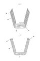
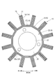
- FIG. 8 is a sectional view taken along line VIII-VIII in FIG. It is explanatory drawing which shows the rotation stop with respect to the frame
- the core 1 is a stator core used for the stator 3 of the generator 2 as a rotating electrical machine, for example, and the generator 2 is mounted on a vehicle, for example, and is driven to rotate by the output of the internal combustion engine. That is, the generator 2 includes a rotor 5 fixed to the crankshaft 4 and rotated by the output of the internal combustion engine, and a stator 3 to which a coil 6 is attached and disposed on the inner peripheral side of the rotor 5 (see FIG. 1). .) The generator 2 generates power by inducing an electromotive force in the coil 6 by the magnetic flux generated by the magnet 7 mounted on the rotor 5.
- the core 1 includes a cylindrical yoke 9 and a plurality of teeth 10 protruding from the yoke 9 to the outer peripheral side and wound with a coil 6.
- the steel plate 11 used as the raw material of the core 1 is provided as what exhibits a substantially U-shaped cross section by bending the material after stamping by the press. That is, the steel plate 11 is bent so as to have a bottom portion 12 and two side portions 13 sandwiching the bottom portion 12. Then, a skeleton 15 of the core 1 is configured by combining a plurality of lamination units 14 formed by laminating a plurality of steel plates 11 (see FIGS. 2 to 5 and the like).
- the lamination unit 14 includes a bottom lamination portion 17 in which the bottom portion 12 is stacked, and two side lamination portions 18 in which the side portions 13 are stacked.
- the skeleton 15 is configured by arranging a plurality of stacked units 14 in a ring shape. At this time, a plurality of bottom laminated portions 17 are combined to form a cylindrical portion 19 on the inner peripheral side, and the side laminated portion 18 protrudes to the outer peripheral side.
- one tooth 10 is constituted by two side laminated portions 18 that are adjacent to each other in the circumferential direction in a combination of two laminated units 14 that are adjacent in the circumferential direction. That is, in the combination of two adjacent lamination units 14, the side lamination part 18 located on the other circumferential side of the two side lamination parts 18 of the lamination unit 14 on the one circumferential side and the lamination on the other circumferential side. Of the two side laminated portions 18 of the unit 14, the side laminated portion 18 located on one side in the circumferential direction abuts in the circumferential direction to form one tooth 10.
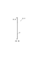
- the edge part 13 is provided with a collar part 20 that extends to both ends in the axial direction when incorporated as the skeleton 15 or the core 1, and the collar part 20 is also stacked similarly to the bottom part 12 and the side part 13.
- the heel laminated portion 21 is configured.
- the eaves layer portion 21 reinforces the delivery of magnetic flux between the core 1 and the magnet 7, and the amount of protrusion in the axial direction is determined according to the axial length of the magnet 7.
- the core 1 includes the following positioning body 22 and first and second engagement pieces 23 and 24 (see FIGS. 4 to 8 and the like).
- the positioning body 22 is disposed on the inner periphery of the cylindrical portion 19 and contacts the inner periphery of the plurality of bottom stacked portions 17 to position the plurality of stacked units 14 in the radial direction.
- the positioning body 22 is formed by laminating substantially annular plate-shaped steel plates 25 in the axial direction, and constitutes the yoke 9 together with the cylindrical portion 19.
- the outer peripheral edge of the steel plate 25 is a regular polygonal shape having the same number of sides as the cylindrical portion 19, and the inner peripheral edge is a concentric circle with the outer peripheral edge.
- circular holes 25a are opened through the steel plate 25 in the axial direction at an angular interval of 120 °, for example.
- the some steel plate 25 is laminated
- the positioning body 22 is disposed on the inner periphery of the cylindrical portion 19 and the outer periphery is brought into contact with the inner periphery of the bottom laminated portion 17, whereby the outer periphery of the positioning body 22 functions as a detent for the skeleton 15.
- the positioning body 22 has a cylindrical surface 27 on the inner periphery, and has three through holes 28 at an angular interval of 120 °.
- the first engaging piece 23 is hooked to the outer periphery of the bottom laminated portion 17 from one axial end side and the outer peripheral side of the bottom laminated portion 17, and the second engaging piece 24 is the shaft of the bottom laminated portion 17. It is caught on the outer periphery of the bottom laminated portion 17 from the other end side in the direction and from the outer peripheral side (see FIG. 1B).
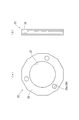
- first and second engaging pieces 23 and 24 are a part of the following first and second restraining bodies 30 and 31. That is, the first and second restraining bodies 30 and 31 are members that are provided in the shape of an annular plate that is substantially the same shape as the steel plate 25 and are arranged coaxially with the cylindrical portion 19, respectively. 23 and 24 extend from the outer peripheral edge of each of the first and second restraining bodies 30 and 31 to the outer peripheral side. Furthermore, circular holes 30a and 31a are opened through the first and second restraining bodies 30 and 31 in the axial direction at an angular interval of 120 ° as in the case of the steel plate 25.
- the first and second restraining bodies 30 and 31 are arranged at one end and the other end of the positioning body 22 in the axial direction, respectively.
- the first and second engaging pieces 23 and 24 are bent in advance and are perpendicular to the annular plate-shaped main bodies 30b and 31b, respectively.
- the 1st, 2nd restraint bodies 30 and 31 are arrange
- the inner circumferences of the first and second restraining bodies 30 and 31 constitute the same cylindrical surface 27 as the inner circumference of the positioning body 22.
- first and second restraining bodies 30 and 31 are arranged so that the positions of the holes 30 a and 31 a coincide with the position of the through hole 28 in the circumferential direction, and the holes 30 a and 31 a form a part of the through hole 28. .
- the skeleton 15, the positioning body 22, and the first and second restraining bodies 30 and 31 are loosened by bringing the tips of the first and second engagement pieces 23 and 24 into contact with the outer periphery of the bottom laminated portion 17 by temporary caulking.
- the core 1 has the three through holes 28 at an angular interval of 120 ° and the cylindrical surface 27 on the inner periphery.
- the stator 3 is fitted into the cover 33 which is a member on the internal combustion engine side and is fastened with screws.
- the cylindrical surface 27 that forms the inner periphery of the core 1 is fitted on the cylinder 24 provided on the cover 33.
- the stator 3 is mounted on the vehicle by screwing the core 1 to the through hole 28 through the shaft portion 36a of the bolt 36 in a state where the core 1 is fitted on the cylinder 24.
- the tips of the first and second engaging pieces 23 and 24 are brought into contact with the outer periphery of the bottom laminated portion 17 by main caulking, and the skeleton 15, the positioning body 22 and the first and second restraining bodies 30, 31 is firmly integrated as a core 1.
- the shaft portion 36 a is screwed into a screw hole 37 provided in the cover 33.
- the steel plate 11 as a raw material is bent so as to have two sides 13 sandwiching the bottom 12 and the bottom 12, and a plurality of lamination units 14 formed by laminating a plurality of steel plates 11,
- the skeleton 15 is configured by combining them. Further, the skeleton 15 is configured by arranging a plurality of laminated units 14 in an annular shape, and a plurality of bottom laminated parts 17 in which the bottoms 12 of the laminated units 14 are stacked together form a cylindrical portion 19 on the inner peripheral side.
- the laminated portion 18 protrudes to the outer peripheral side.
- the cylindrical portion 19 of the skeleton 15 forms part of the yoke 9, and the side laminated portion 18 forms the teeth 10.
- the core 1 includes the following positioning body 22 and first and second engagement pieces 23 and 24.
- the positioning body 22 is disposed on the inner periphery of the cylindrical portion 19 and contacts the inner periphery of the plurality of bottom stacked portions 17 to position the plurality of stacked units 14 in the radial direction.
- the first engagement piece 23 is hooked on the outer periphery of the bottom laminated portion 17 from the one axial end side and the outer peripheral side of the bottom laminated portion 17.
- the second engagement piece 24 is hooked on the outer periphery of the bottom stacked portion 17 from the other axial end side and the outer peripheral side of the bottom stacked portion 17.
- the integrity as the core 1 can be maintained by holding the cylindrical portion 19 present on the inner periphery of the side laminated portion 18. For this reason, even if the number of teeth 10 increases, the integrity as the core 1 can be maintained regardless of the size of the tolerance.
- the positioning body 22 of the embodiment is provided by laminating the steel plates 25 in the axial direction, but the mode of the positioning body 22 is not limited to the embodiment.
- the positioning body 22 may be provided by a material other than the magnetic material.
- the positioning body 22 may be provided by a resin material.
- the positioning body 22 of the Example was functioning as a detent with respect to the frame
- the aspect of a detent is not limited to an Example.
- a small protrusion 40 that fits in a gap 39 formed between the bottom laminated portions 17 adjacent in the circumferential direction is provided on the steel plate 25, and the small protrusion 40 is fitted in the gap 39 to prevent rotation.
- the function may be exhibited.
- the core 1 of the embodiment was loosely integrated by temporary caulking before screwing to the cover 33 and then firmly integrated by main caulking after screw tightening. It may be firmly integrated by caulking.
- the core 1 of the embodiment was used as a stator core of the generator 2, the core 1 may be used for an electric motor such as a synchronous motor, an induction motor, and a reluctance motor, and the core 1 is used as a rotor core. Also good.
Landscapes
- Engineering & Computer Science (AREA)
- Power Engineering (AREA)
- Iron Core Of Rotating Electric Machines (AREA)
Abstract
回転電機のコア(1)は、位置決め体(22)および第1、第2係合片(23、24)を備える。まず、位置決め体(22)は、筒部分(19)の内周に配置され、底積層部(17)の内周に当接して積層単位を径方向に位置決めする。また、第1係合片(23)は、底積層部(17)の軸方向一端側かつ外周側から底積層部(17)の外周に引っ掛かる。さらに、第2係合片(24)は、底積層部(17)の軸方向他端側かつ外周側から底積層部(17)の外周に引っ掛かる。これにより、筒部分(19)を保持することで、コア(1)としての一体性を保つことができる。このため、ティース(10)の数が増えても、公差の大きさにかかわりなく、コア(1)としての一体性を保つことができる。
Description
本発明は、回転電機のコアに関する。
従来から、回転電機のコアでは、いわゆる磁束の短絡を抑制するため、周方向に鋼板を積層することでティースを構成する技術が知られている。また、このようなコアの一例として、リラクタンスモータの回転子において断面が略L字を呈する鋼板を積層してL字の積層単位を構成し、積層単位のL字の両辺により突極(ティース)を構成するものが公知である(例えば、特許文献1参照。)。そして、特許文献1の回転子によれば、コアとしての一体性を保つため、ホルダが用いられている。
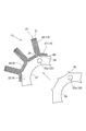
ところで、図10に示すように、回転電機においてティース101の数が増えると、公差が大きくなり、周方向に隣り合う辺102間の隙間103が大きくなりやすい。
しかし、特許文献1のホルダは、2つの爪部104によりティース101を周方向に挟むことでコア100としての一体性を保つものである。このため、ティース101の数が増えると、辺102間の隙間103の増大によりホルダを装着することができない虞が高まる。
しかし、特許文献1のホルダは、2つの爪部104によりティース101を周方向に挟むことでコア100としての一体性を保つものである。このため、ティース101の数が増えると、辺102間の隙間103の増大によりホルダを装着することができない虞が高まる。
本発明は、上記背景に鑑みてなされたものであり、回転電機のコアにおいて、ティースの数が増えても、コアとしての一体性を保つことができる構成を提供することを望んで得られたものである。
本発明に係る回転電機のコアは、その一態様として、筒状のヨーク、および、ヨークから外周側に突出する複数のティースを具備する。また、素材となる鋼板は、底部および底部を挟む2つの辺部を有するように折れ曲がり、鋼板を複数枚積層してなる積層単位を、複数、組み合わせることでコアの骨格が構成される。また、骨格では、積層単位の内の底部が積み重なる底積層部が複数組み合わさって内周側で筒部分を形成するように、かつ、辺部が積み重なる辺積層部が外周側に突出するように、複数の積層単位が環状に配置される。そして、骨格の内、筒部分がヨークの全部または一部をなすとともに、外周側に突出する辺積層部がティースの全部または一部をなす。
さらに、コアは、次の位置決め体および第1、第2係合片を備える。まず、位置決め体は、筒部分の内周に配置され、複数の底積層部の内周に当接して複数の積層単位を径方向に位置決めする。また、第1係合片は、底積層部の軸方向一端側かつ外周側から底積層部の外周に引っ掛かる。さらに、第2係合片は、底積層部の軸方向他端側かつ外周側から底積層部の外周に引っ掛かる。
これにより、辺部よりも内周に存在する筒部分を保持することで、コアとしての一体性を保つことができる。このため、ティースの数が増えても、公差の大きさにかかわりなく、コアとしての一体性を保つことができる。
本発明の回転電機のコアを、実施例を用いて説明する。
〔実施例の構成〕
本発明の実施例のコア1の構成を、図1~図8を用いて説明する。
コア1は、例えば、回転電機としての発電機2のステータ3に用いられるステータコアであり、発電機2は、例えば、車両に搭載されて内燃機関の出力により回転駆動される。
すなわち、発電機2は、クランクシャフト4に固定されて内燃機関の出力により回転するロータ5と、コイル6が装着されてロータ5の内周側に配置されるステータ3とを備える(図1参照。)。そして、発電機2は、ロータ5に装着された磁石7が発生する磁束によりコイル6に起電力を誘導して発電する。
本発明の実施例のコア1の構成を、図1~図8を用いて説明する。
コア1は、例えば、回転電機としての発電機2のステータ3に用いられるステータコアであり、発電機2は、例えば、車両に搭載されて内燃機関の出力により回転駆動される。
すなわち、発電機2は、クランクシャフト4に固定されて内燃機関の出力により回転するロータ5と、コイル6が装着されてロータ5の内周側に配置されるステータ3とを備える(図1参照。)。そして、発電機2は、ロータ5に装着された磁石7が発生する磁束によりコイル6に起電力を誘導して発電する。
コア1は、円筒状のヨーク9、および、ヨーク9から外周側に突出してコイル6が巻かれる複数のティース10を具備する。また、コア1の素材となる鋼板11は、プレスによる打ち抜き後の材料に曲げ加工を施すことで、断面略U字を呈するものとして設けられる。すなわち、鋼板11は、底部12および底部12を挟む2つの辺部13を有するように折れ曲がっている。そして、鋼板11を複数枚積層してなる積層単位14を、複数、組み合わせることでコア1の骨格15が構成される(図2~図5等参照)。
ここで、積層単位14は、底部12が積み重なる底積層部17、辺部13が積み重なる2つの辺積層部18からなる。そして、骨格15は複数の積層単位14が環状に配置されて構成される。このとき、底積層部17は複数組み合わさって内周側で筒部分19を形成し、辺積層部18は外周側に突出する。
そして、骨格15の内、筒部分19がヨーク9の一部をなす。
また、周方向に隣り合う2つの積層単位14の組合せにおいて周方向に隣り合って当接する2つの辺積層部18により1つのティース10が構成される。すなわち、隣り合う2つの積層単位14の組合せにおいて、周方向一方側の積層単位14の2つの辺積層部18の内、周方向他方側に位置する辺積層部18と、周方向他方側の積層単位14の2つの辺積層部18の内、周方向一方側に位置する辺積層部18とが周方向に当接して1つのティース10をなす。
また、周方向に隣り合う2つの積層単位14の組合せにおいて周方向に隣り合って当接する2つの辺積層部18により1つのティース10が構成される。すなわち、隣り合う2つの積層単位14の組合せにおいて、周方向一方側の積層単位14の2つの辺積層部18の内、周方向他方側に位置する辺積層部18と、周方向他方側の積層単位14の2つの辺積層部18の内、周方向一方側に位置する辺積層部18とが周方向に当接して1つのティース10をなす。
なお、辺部13の先端には、骨格15やコア1として組み入れられたときに軸方向両端に伸びる鍔部20が設けられており、鍔部20も底部12や辺部13と同様に積み重なって鍔積層部21を構成する。ここで、鍔積層部21は、コア1と磁石7との磁束の受渡を強化するものであり、磁石7の軸方向長さに応じて軸方向への突出量が決められている。
さらに、コア1は、以下の位置決め体22および第1、第2係合片23、24を備える(図4~図8等参照。)。
まず、位置決め体22は、筒部分19の内周に配置され、複数の底積層部17の内周に当接して複数の積層単位14を径方向に位置決めする。ここで、位置決め体22は、略円環板状の鋼板25を軸方向に積層したものであり、筒部分19とともにヨーク9を構成する。
まず、位置決め体22は、筒部分19の内周に配置され、複数の底積層部17の内周に当接して複数の積層単位14を径方向に位置決めする。ここで、位置決め体22は、略円環板状の鋼板25を軸方向に積層したものであり、筒部分19とともにヨーク9を構成する。
また、鋼板25の外周縁は、筒部分19と同数の辺を有する正多角形状であり、内周縁は、外周縁と同心の円形である。さらに、鋼板25には、例えば、120°の角度間隔で円形の穴25aが軸方向に貫通して開いている。そして、複数の鋼板25は、穴25aの位置が周方向に関して一致するように、かつ、外周が正多角柱の側面となるように積層される。これにより、位置決め体22を筒部分19の内周に配置して外周を底積層部17の内周に当接させることで、位置決め体22の外周は骨格15に対する回り止めとして機能する。また、位置決め体22は、内周が円筒面27になり、120°の角度間隔で3つの貫通穴28を有する。
次に、第1係合片23は、底積層部17の軸方向一端側かつ外周側から底積層部17の外周に引っ掛かるものであり、第2係合片24は、底積層部17の軸方向他端側かつ外周側から底積層部17の外周に引っ掛かるものである(図1(b)参照。)。
また、第1、第2係合片23、24は、次の第1、第2拘束体30、31の一部である。すなわち、第1、第2拘束体30、31は、それぞれ鋼板25と略同形の円環板状に設けられて筒部分19と同軸に配置される部材であり、第1、第2係合片23、24は、第1、第2拘束体30、31それぞれの外周縁から外周側に伸びる。さらに、第1、第2拘束体30、31には、それぞれ鋼板25と同様に120°の角度間隔で円形の穴30a、31aが軸方向に貫通して開いている。
そして、第1、第2拘束体30、31は、それぞれ位置決め体22の軸方向一端、他端に配置される。なお、第1、第2係合片23、24は、予め曲げられており、それぞれ円環板状の本体30b、31bに対し垂直になっている。そして、第1、第2拘束体30、31は、それぞれ第1、第2係合片23、24の先端が底積層部17の外周側で軸方向他端側、一端側を向くように配置される。また、第1、第2拘束体30、31の内周は、位置決め体22の内周と同じ円筒面27を構成する。さらに、第1、第2拘束体30、31は、穴30a、31aの位置が貫通穴28の位置と周方向に関して一致するように配置され、穴30a、31aは貫通穴28の一部をなす。
そして、第1、第2係合片23、24の先端を仮かしめにより底積層部17の外周に接触させることで、骨格15、位置決め体22および第1、第2拘束体30、31を緩やかに一体化し、コア1としての概形を構成する(図5参照。)。
以上により、コア1は、120°の角度間隔で3つの貫通穴28を有するとともに、内周に円筒面27を有するものとなる。
以上により、コア1は、120°の角度間隔で3つの貫通穴28を有するとともに、内周に円筒面27を有するものとなる。
そして、ティース10にコイル6を巻いてステータ3を構成した後、ステータ3を内燃機関側の部材であるカバー33に嵌めてネジ締結する。ここで、コア1の内周をなす円筒面27は、カバー33に設けられた円筒24に外嵌めされる。そして、コア1を円筒24に外嵌めした状態で貫通穴28にボルト36の軸部36aを通してネジ締結することで、ステータ3が車両に搭載される。また、ネジ締結後、第1、第2係合片23、24の先端を本かしめにより底積層部17の外周に当接させ、骨格15、位置決め体22および第1、第2拘束体30、31をコア1として強固に一体化する。なお、軸部36aは、カバー33に設けられたネジ穴37に螺合する。
〔実施例の効果〕
実施例のコア1によれば、素材となる鋼板11は、底部12および底部12を挟む2つの辺部13を有するように折れ曲がり、鋼板11を複数枚積層してなる積層単位14を、複数、組み合わせることで骨格15が構成される。また、骨格15は複数の積層単位14が環状に配置されて構成され、積層単位14の内の底部12が積み重なる底積層部17が複数組み合わさって内周側で筒部分19を形成し、辺積層部18が外周側に突出する。そして、骨格15の内、筒部分19がヨーク9の一部をなすとともに、辺積層部18がティース10をなす。
実施例のコア1によれば、素材となる鋼板11は、底部12および底部12を挟む2つの辺部13を有するように折れ曲がり、鋼板11を複数枚積層してなる積層単位14を、複数、組み合わせることで骨格15が構成される。また、骨格15は複数の積層単位14が環状に配置されて構成され、積層単位14の内の底部12が積み重なる底積層部17が複数組み合わさって内周側で筒部分19を形成し、辺積層部18が外周側に突出する。そして、骨格15の内、筒部分19がヨーク9の一部をなすとともに、辺積層部18がティース10をなす。
さらに、コア1は、次の位置決め体22および第1、第2係合片23、24を備える。まず、位置決め体22は、筒部分19の内周に配置され、複数の底積層部17の内周に当接して複数の積層単位14を径方向に位置決めする。また、第1係合片23は、底積層部17の軸方向一端側かつ外周側から底積層部17の外周に引っ掛かる。さらに、第2係合片24は、底積層部17の軸方向他端側かつ外周側から底積層部17の外周に引っ掛かる。
これにより、辺積層部18よりも内周に存在する筒部分19を保持することで、コア1としての一体性を保つことができる。このため、ティース10の数が増えても、公差の大きさにかかわりなく、コア1としての一体性を保つことができる。
これにより、辺積層部18よりも内周に存在する筒部分19を保持することで、コア1としての一体性を保つことができる。このため、ティース10の数が増えても、公差の大きさにかかわりなく、コア1としての一体性を保つことができる。
〔変形例〕
コア1の構成は、実施例に限定されず、種々の変形例を考えることができる。
例えば、実施例の位置決め体22は、鋼板25を軸方向に積層することで設けられていたが、位置決め体22の態様は実施例に限定されない。例えば、磁性材料以外の材料により位置決め体22を設けてもよく、例えば、樹脂材料により位置決め体22を設けてもよい。
コア1の構成は、実施例に限定されず、種々の変形例を考えることができる。
例えば、実施例の位置決め体22は、鋼板25を軸方向に積層することで設けられていたが、位置決め体22の態様は実施例に限定されない。例えば、磁性材料以外の材料により位置決め体22を設けてもよく、例えば、樹脂材料により位置決め体22を設けてもよい。
また、実施例の位置決め体22は、外周を正多角柱の側面とすることで、骨格15に対する回り止めとして機能させていたが、回り止めの態様は実施例に限定されない。例えば、図9に示すように、周方向に隣り合う底積層部17の間に形成される隙間39に嵌る小突起40を鋼板25に設け、小突起40を隙間39に嵌めることで回り止めの機能を発揮してもよい。
また、実施例のコア1は、カバー33へのネジ締結前に仮かしめにより緩やかに一体化された後、ネジ締結後に本かしめにより強固に一体化されていたが、例えば、ネジ締結前に本かしめにより強固に一体化してもよい。
また、実施例のコア1は、カバー33へのネジ締結前に仮かしめにより緩やかに一体化された後、ネジ締結後に本かしめにより強固に一体化されていたが、例えば、ネジ締結前に本かしめにより強固に一体化してもよい。
さらに、実施例のコア1は、発電機2のステータコアとして利用されていたが、同期モータ、誘導モータおよびリラクタンスモータ等の電動機にコア1を利用してもよく、ロータコアとしてコア1を利用してもよい。
1 コア
2 発電機(回転電機)
9 ヨーク
10 ティース
11 鋼板
12 底部
13 辺部
14 積層単位
15 骨格
17 底積層部
18 辺積層部
19 筒部分
22 位置決め体
23 第1係合片
24 第2係合片
2 発電機(回転電機)
9 ヨーク
10 ティース
11 鋼板
12 底部
13 辺部
14 積層単位
15 骨格
17 底積層部
18 辺積層部
19 筒部分
22 位置決め体
23 第1係合片
24 第2係合片
Claims (3)
- 筒状のヨーク(9)、および、このヨーク(9)から外周側に突出する複数のティース(10)を具備する回転電機(2)のコア(1)において、
素材となる鋼板(11)は、底部(12)およびこの底部(12)を挟む2つの辺部(13)を有するように折れ曲がり、
前記鋼板(11)を複数枚積層してなる積層単位(14)を、複数、組み合わせることで前記コア(1)の骨格(15)が構成され、
この骨格(15)では、前記積層単位(14)の内の前記底部(12)が積み重なる底積層部(17)が複数組み合わさって内周側で筒部分(19)を形成するように、かつ、前記辺部(13)が積み重なる辺積層部(18)が外周側に突出するように、複数の前記積層単位(14)が環状に配置され、
前記骨格(15)の内、前記筒部分(19)が前記ヨーク(9)の全部または一部をなすとともに、外周側に突出する前記辺積層部(18)が前記ティース(10)の全部または一部をなし、
前記筒部分(19)の内周に配置され、複数の前記底積層部(17)の内周に当接して複数の前記積層単位(14)を径方向に位置決めする位置決め体(22)と、
前記底積層部(17)の軸方向一端側かつ外周側から前記底積層部(17)の外周に引っ掛かる第1係合片(23)と、
前記底積層部(17)の軸方向他端側かつ外周側から前記底積層部(17)の外周に引っ掛かる第2係合片(24)とを備えることを特徴とする回転電機(2)のコア(1)。 - 請求項1に記載の回転電機(2)のコア(1)において、
前記第1、第2係合片(23、24)は、それぞれ円環状に設けられて前記筒部分(19)と同軸に配置される第1、第2拘束体(30、31)の一部であり、この第1、第2拘束体(30、31)それぞれの外周縁から外周側に伸びるものであり、
前記第1、第2拘束体(30、31)は、それぞれ前記位置決め体(22)の軸方向一端、他端に配置されることを特徴とする回転電機(2)のコア(1)。 - 請求項1または請求項2の回転電機(2)のコア(1)において、
前記コア(1)はステータコアであり、前記ティース(10)にコイル(6)が巻かれることを特徴とする回転電機(2)のコア(1)。
Applications Claiming Priority (2)
| Application Number | Priority Date | Filing Date | Title |
|---|---|---|---|
| JP2013210689A JP2015076941A (ja) | 2013-10-08 | 2013-10-08 | 回転電機のコア |
| JP2013-210689 | 2013-10-08 |
Publications (1)
| Publication Number | Publication Date |
|---|---|
| WO2015053229A1 true WO2015053229A1 (ja) | 2015-04-16 |
Family
ID=52813045
Family Applications (1)
| Application Number | Title | Priority Date | Filing Date |
|---|---|---|---|
| PCT/JP2014/076718 Ceased WO2015053229A1 (ja) | 2013-10-08 | 2014-10-06 | 回転電機のコア |
Country Status (2)
| Country | Link |
|---|---|
| JP (1) | JP2015076941A (ja) |
| WO (1) | WO2015053229A1 (ja) |
Citations (5)
| Publication number | Priority date | Publication date | Assignee | Title |
|---|---|---|---|---|
| JPS484905U (ja) * | 1971-06-04 | 1973-01-20 | ||
| JPS5359810A (en) * | 1976-10-05 | 1978-05-30 | Bogue Elec Mfg Co | Ac synchronous magnetic reluctance motor |
| JPS567476U (ja) * | 1979-06-28 | 1981-01-22 | ||
| JPH0629359U (ja) * | 1992-09-01 | 1994-04-15 | 株式会社安川電機 | リラクタンスモータの回転子 |
| JPH1080116A (ja) * | 1996-07-08 | 1998-03-24 | Toyota Motor Corp | リラクタンスモータ |
-
2013
- 2013-10-08 JP JP2013210689A patent/JP2015076941A/ja active Pending
-
2014
- 2014-10-06 WO PCT/JP2014/076718 patent/WO2015053229A1/ja not_active Ceased
Patent Citations (5)
| Publication number | Priority date | Publication date | Assignee | Title |
|---|---|---|---|---|
| JPS484905U (ja) * | 1971-06-04 | 1973-01-20 | ||
| JPS5359810A (en) * | 1976-10-05 | 1978-05-30 | Bogue Elec Mfg Co | Ac synchronous magnetic reluctance motor |
| JPS567476U (ja) * | 1979-06-28 | 1981-01-22 | ||
| JPH0629359U (ja) * | 1992-09-01 | 1994-04-15 | 株式会社安川電機 | リラクタンスモータの回転子 |
| JPH1080116A (ja) * | 1996-07-08 | 1998-03-24 | Toyota Motor Corp | リラクタンスモータ |
Also Published As
| Publication number | Publication date |
|---|---|
| JP2015076941A (ja) | 2015-04-20 |
Similar Documents
| Publication | Publication Date | Title |
|---|---|---|
| JP6022077B2 (ja) | 回転電機用ロータ | |
| US7368844B2 (en) | Magnetoelectric generator | |
| WO2015087126A2 (en) | Rotary electric machine rotor | |
| US10833569B2 (en) | Rotor core, rotor, motor, manufacturing method of rotor core, and manufacturing method of rotor | |
| JP2015100227A (ja) | 回転電機ロータ | |
| JP2013233030A (ja) | 始動発電機 | |
| JPWO2018225296A1 (ja) | ロータ及び回転機 | |
| JP6549801B2 (ja) | 内燃機関用回転電機 | |
| JP2012235652A (ja) | 回転子および回転電機 | |
| US11056938B2 (en) | Rotor and motor | |
| JPWO2015151274A1 (ja) | 回転電機の固定子及びその製造方法 | |
| JP6136477B2 (ja) | 回転電機およびその製造方法 | |
| JP5864839B2 (ja) | 電動パワーステアリング装置用左右回転型ブラシレスモータの製造方法 | |
| WO2014024973A1 (ja) | 電機子、および、これを用いた回転電機 | |
| JP2015015873A (ja) | 回転電気機械及び鞍乗型車両 | |
| JP5842665B2 (ja) | レゾルバステータの固定構造 | |
| JP6515322B2 (ja) | 回転電機の固定子 | |
| JP2012016216A (ja) | 回転電機 | |
| JP2015033254A5 (ja) | ステータコアアセンブリ | |
| WO2015053229A1 (ja) | 回転電機のコア | |
| JP5314115B2 (ja) | レゾルバ | |
| JP5749639B2 (ja) | 固定子 | |
| CN105612678B (zh) | 旋转电机的铁芯 | |
| JP5155689B2 (ja) | 回転電機 | |
| JP2016026468A (ja) | 電動パワーステアリング装置用ブラシレスモータ製造方法 |
Legal Events
| Date | Code | Title | Description |
|---|---|---|---|
| 121 | Ep: the epo has been informed by wipo that ep was designated in this application |
Ref document number: 14851902 Country of ref document: EP Kind code of ref document: A1 |
|
| NENP | Non-entry into the national phase |
Ref country code: DE |
|
| 122 | Ep: pct application non-entry in european phase |
Ref document number: 14851902 Country of ref document: EP Kind code of ref document: A1 |