WO2015053221A1 - 回転電機のコア - Google Patents
回転電機のコア Download PDFInfo
- Publication number
- WO2015053221A1 WO2015053221A1 PCT/JP2014/076694 JP2014076694W WO2015053221A1 WO 2015053221 A1 WO2015053221 A1 WO 2015053221A1 JP 2014076694 W JP2014076694 W JP 2014076694W WO 2015053221 A1 WO2015053221 A1 WO 2015053221A1
- Authority
- WO
- WIPO (PCT)
- Prior art keywords
- core
- electrical machine
- rotating electrical
- yoke
- steel plate
- Prior art date
- Legal status (The legal status is an assumption and is not a legal conclusion. Google has not performed a legal analysis and makes no representation as to the accuracy of the status listed.)
- Ceased
Links
Images




Classifications
-
- H—ELECTRICITY
- H02—GENERATION; CONVERSION OR DISTRIBUTION OF ELECTRIC POWER
- H02K—DYNAMO-ELECTRIC MACHINES
- H02K1/00—Details of the magnetic circuit
- H02K1/06—Details of the magnetic circuit characterised by the shape, form or construction
- H02K1/12—Stationary parts of the magnetic circuit
- H02K1/18—Means for mounting or fastening magnetic stationary parts on to, or to, the stator structures
- H02K1/187—Means for mounting or fastening magnetic stationary parts on to, or to, the stator structures to inner stators
-
- H—ELECTRICITY
- H02—GENERATION; CONVERSION OR DISTRIBUTION OF ELECTRIC POWER
- H02K—DYNAMO-ELECTRIC MACHINES
- H02K1/00—Details of the magnetic circuit
- H02K1/06—Details of the magnetic circuit characterised by the shape, form or construction
- H02K1/12—Stationary parts of the magnetic circuit
- H02K1/14—Stator cores with salient poles
- H02K1/146—Stator cores with salient poles consisting of a generally annular yoke with salient poles
- H02K1/148—Sectional cores
Definitions
- the present invention relates to a core of a rotating electric machine.
- a technique for forming teeth by laminating steel plates in the circumferential direction is known in order to suppress a so-called magnetic flux short circuit.
- a reluctance motor rotor is formed by laminating steel sheets having a substantially L-shaped cross section to form an L-shaped laminated unit, and salient poles (teeth) are formed by both sides of the L-shaped laminated unit.
- a substantially L-shaped steel plate is superior in terms of material cost because it has fewer discarded portions than a steel plate provided so as to be laminated in the axial direction.
- a core used for an outer see, for example, Patent Document 2
- the superiority of material cost is more remarkable. become.
- the demand for cost reduction is increasing, and there is a demand for further measures for reducing waste.
- the present invention has been made to solve the above-described problems, and an object of the present invention is to provide a core of a rotating electrical machine that can further reduce a waste portion when a steel plate is provided by punching with a press. .
- the core of the rotating electrical machine of the present application includes a cylindrical yoke and a plurality of teeth protruding from the yoke to the outer peripheral side.
- the steel plate used as a raw material is bent so as to have two sides that sandwich the bottom and the bottom, and a core skeleton is configured by combining a plurality of lamination units formed by laminating a plurality of steel plates.
- a plurality of bottom laminated portions in which the bottom portions of the laminated units are stacked are combined to form a cylindrical portion on the inner peripheral side, and a side laminated portion in which the side portions are stacked protrudes to the outer peripheral side.
- a plurality of stacked units are arranged in a ring shape.
- the cylindrical portion of the skeleton forms all or part of the yoke, and the side laminated portion protruding to the outer peripheral side forms all or part of the teeth.
- Some of the steel plates are deformed steel plates having protruding pieces that can be bent at the bottom and protrude toward the inner peripheral side of the yoke, and a hole penetrates the protruding pieces. Thereby, since a part of discard part can be included in a deformation
- a protrusion piece can be utilized as an attachment piece at the time of attaching a core to another member.
- the core 1 is a stator core used for the stator 3 of the generator 2 as a rotating electrical machine, for example, and the generator 2 is mounted on a vehicle, for example, and is driven to rotate by the output of the internal combustion engine. That is, the generator 2 includes a rotor 5 fixed to the crankshaft 4 and rotated by the output of the internal combustion engine, and a stator 3 to which a coil 6 is attached and disposed on the inner peripheral side of the rotor 5 (see FIG. 1). .) The generator 2 generates power by inducing an electromotive force in the coil 6 by the magnetic flux generated by the magnet 7 mounted on the rotor 5.
- the core 1 includes a cylindrical yoke 9 and a plurality of teeth 10 protruding from the yoke 9 to the outer peripheral side and wound with a coil 6.
- the steel plate 11 used as the raw material of the core 1 is provided as a material having a substantially U-shaped cross section by bending the material 11a after being punched by a press. That is, the steel plate 11 is bent so as to have a bottom portion 12 and two side portions 13 sandwiching the bottom portion 12. Then, a skeleton 15 of the core 1 is configured by combining a plurality of lamination units 14 formed by laminating a plurality of steel plates 11 (see FIGS. 2 to 6 and the like).
- the lamination unit 14 includes a bottom lamination portion 17 in which the bottom portion 12 is stacked, and two side lamination portions 18 in which the side portions 13 are stacked.
- the skeleton 15 is configured by arranging a plurality of stacked units 14 in a ring shape. At this time, a plurality of bottom laminated portions 17 are combined to form a cylindrical portion 19 on the inner peripheral side, and the side laminated portion 18 protrudes to the outer peripheral side.
- one tooth 10 is constituted by two side laminated portions 18 that are adjacent to each other in the circumferential direction in a combination of two laminated units 14 that are adjacent in the circumferential direction. That is, in the combination of two adjacent lamination units 14, the side lamination part 18 located on the other circumferential side of the two side lamination parts 18 of the lamination unit 14 on the one circumferential side and the lamination on the other circumferential side. Of the two side laminated portions 18 of the unit 14, the side laminated portion 18 located on one side in the circumferential direction abuts in the circumferential direction to form one tooth 10.
- the edge part 13 is provided with a collar part 20 that extends to both ends in the axial direction when incorporated as the skeleton 15 or the core 1, and the collar part 20 is also stacked similarly to the bottom part 12 and the side part 13.
- the heel laminated portion 21 is configured.
- the eaves layer portion 21 reinforces the delivery of magnetic flux between the core 1 and the magnet 7, and the amount of protrusion in the axial direction is determined according to the axial length of the magnet 7.
- some of the steel plates 11 are deformed steel plates 24 having protruding pieces 23 that can be bent toward the inner peripheral side of the yoke 9 by bending a part of the bottom 12. Further, a hole 25 passes through the protruding piece 23.
- the protruding piece 23 is a portion that projects in the same plane perpendicular to the longitudinal direction in the material 11 a before bending.
- two protruding pieces 23 are provided, and the two protruding pieces 23 are line-symmetric with respect to the longitudinal axis on both sides in the width direction of the material 11a.
- the deformed steel plate 24 is disposed on the outermost periphery, and the protruding pieces 23 are disposed on the first end side and the second end side in the axial direction of the yoke 9.
- the protruding piece 23 is bent vertically toward the inner peripheral side of the yoke 9 and protrudes toward the inner peripheral side of the yoke 9 on the first end side and the second end side in the axial direction of the yoke 9.
- the laminated units 14A are incorporated at three locations so as to exist at an angular interval of 120 °.
- a collar 27, which is a cylindrical member, is disposed between the two projecting pieces 23, and the inner periphery of the collar 27 constitutes a through hole 28 together with the hole 25 (see FIGS. 1 and 7).
- the stator 3 is fitted into the cover 30 which is a member on the internal combustion engine side and is screwed.
- the inner peripheral end of the protruding piece 23 constitutes the inner peripheral end of the core 1 and is externally fitted to a columnar portion 31 that is an attachment portion provided on the cover 30.
- the stator 3 is mounted in a vehicle by carrying out the screw fastening to the through-hole 28 through the axial part 32a of the volt
- the shaft portion 32 a is screwed into a screw hole 33 provided in the cover 30.
- the steel plate 11 as a raw material is bent so as to have two sides 13 sandwiching the bottom 12 and the bottom 12, and a plurality of lamination units 14 formed by laminating a plurality of steel plates 11,
- the skeleton 15 is configured by combining them. Further, the skeleton 15 is configured by arranging a plurality of laminated units 14 in an annular shape, and a plurality of bottom laminated parts 17 in which the bottoms 12 of the laminated units 14 are stacked together form a cylindrical portion 19 on the inner peripheral side.
- the laminated portion 18 protrudes to the outer peripheral side.
- the cylindrical portion 19 of the skeleton 15 forms the yoke 9, and the side laminated portion 18 forms the teeth 10.
- some of the steel plates 11 are deformed steel plates 24 each having a protruding piece 23 that can be bent toward the inner peripheral side of the yoke 9 by bending a part of the bottom portion 12. is doing. Thereby, a part of the discarded portion generated by punching by the press can be included in the deformed steel sheet 24 as the protruding piece 23, so that the discarded portion can be reduced.
- a collar 27 that is a cylindrical member is disposed between the two protruding pieces 23 after being bent. Thereby, when utilizing the protrusion piece 23 for the screw fastening to another member, it can reinforce with respect to fastening force. Further, the inner peripheral end of the projecting piece 23 is externally fitted to the cylindrical portion 31 on the internal combustion engine side. Thereby, when considering attaching the stator 3 by what is called an inlay, it is not necessary to provide another part for fitting.
- the configuration of the core 1 is not limited to the embodiment, and various modifications can be considered.
- the deformed steel plate 24 has two protruding pieces 23, and the two protruding pieces 23 are bent vertically so that the first end side in the axial direction of the yoke 9, the second Although it protrudes to the inner peripheral side of the yoke 9 on the end side, the form of the deformed steel plate 24 and the protruding piece 23 is not limited to the embodiment.
- the deformed steel plate 24 is provided with only one protruding piece 23, and all the steel plates 11 included in the stacked unit 14 ⁇ / b> A are changed to the deformed steel plate 24 having only one protruding piece 23. It may be arranged on one end side and may protrude toward the inner peripheral side of the yoke 9 on the first axial end side of the yoke 9 (see FIG. 8).
- the inner peripheral end of the protruding piece 23 is externally fitted to the cylindrical portion 31 on the internal combustion engine side, but the inlay aspect between the stator 3 and the member on the internal combustion engine side is as follows.
- the present invention is not limited to the examples.
- an inlay between the stator 3 and a member on the internal combustion engine side may be configured by fitting the outer periphery of the collar 27 to the cylindrical portion 31.
- the core 1 of the embodiment was used as a stator core of the generator 2, the core 1 may be used for an electric motor such as a synchronous motor, an induction motor, and a reluctance motor, and the core 1 is used as a rotor core. Also good.
Landscapes
- Engineering & Computer Science (AREA)
- Power Engineering (AREA)
- Iron Core Of Rotating Electric Machines (AREA)
- Manufacture Of Motors, Generators (AREA)
Abstract
コアの素材となる鋼板11に関し、一部の鋼板11は、底部12の一部を折り曲げてヨークの内周側に突出させることができる突出片23を有する変形鋼板24であり、突出片23には、穴25が貫通している。これにより、プレスによる打ち抜きにより発生する廃棄部分の一部を突出片23として変形鋼板24に含ませることができるので、廃棄部分を低減することができる。
Description
本発明は、回転電機のコアに関する。
従来から、回転電機のコアでは、いわゆる磁束の短絡を抑制するため、周方向に鋼板を積層することでティースを構成する技術が知られている。また、このようなコアの一例として、リラクタンスモータの回転子において断面が略L字を呈する鋼板を積層してL字の積層単位を構成し、積層単位のL字の両辺により突極(ティース)を構成するものが公知である(例えば、特許文献1参照。)。
ここで、鋼板をプレスによる打ち抜きで設ける場合、略L字の鋼板は、軸方向に積層するように設けられた鋼板に比べて、廃棄部分が少なくなり素材コストの点で優位である。特に、アウターに使用されるコアの場合(例えば、特許文献2参照。)、軸方向に積層するには、内周が空いた形状に鋼板を設ける必要があり、素材コストの優位性がより顕著になる。
しかし、コストダウンの要求は高まる一方であり、更なる廃棄部分の低減策が求められている。
しかし、コストダウンの要求は高まる一方であり、更なる廃棄部分の低減策が求められている。
本発明は、上記の問題点を解決するためになされたものであり、その目的は、鋼板をプレスによる打ち抜きで設ける場合に廃棄部分を更に低減することができる回転電機のコアを提供するにある。
本願の回転電機のコアは、筒状のヨーク、および、ヨークから外周側に突出する複数のティースを具備する。また、素材となる鋼板は、底部および底部を挟む2つの辺部を有するように折れ曲がり、鋼板を複数枚積層してなる積層単位を、複数、組み合わせることでコアの骨格が構成される。また、骨格では、積層単位の内の底部が積み重なる底積層部が複数組み合わさって内周側で筒部分を形成するように、かつ、辺部が積み重なる辺積層部が外周側に突出するように、複数の積層単位が環状に配置される。そして、骨格の内、筒部分がヨークの全部または一部をなすとともに、外周側に突出する辺積層部がティースの全部または一部をなす。
また、一部の鋼板は、底部の一部を折り曲げてヨークの内周側に突出させることができる突出片を有する変形鋼板であり、突出片には、穴が貫通している。
これにより、廃棄部分の一部を突出片として変形鋼板に含ませることができるので、廃棄部分を低減することができる。なお、突出片は、コアを他部材に取り付ける際の取付片として利用することができる。
これにより、廃棄部分の一部を突出片として変形鋼板に含ませることができるので、廃棄部分を低減することができる。なお、突出片は、コアを他部材に取り付ける際の取付片として利用することができる。
実施形態の回転電機のコアを、実施例を用いて説明する。
〔実施例の構成〕
実施例のコア1の構成を、図1~図7を用いて説明する。
コア1は、例えば、回転電機としての発電機2のステータ3に用いられるステータコアであり、発電機2は、例えば、車両に搭載されて内燃機関の出力により回転駆動される。
すなわち、発電機2は、クランクシャフト4に固定されて内燃機関の出力により回転するロータ5と、コイル6が装着されてロータ5の内周側に配置されるステータ3とを備える(図1参照。)。そして、発電機2は、ロータ5に装着された磁石7が発生する磁束によりコイル6に起電力を誘導して発電する。
実施例のコア1の構成を、図1~図7を用いて説明する。
コア1は、例えば、回転電機としての発電機2のステータ3に用いられるステータコアであり、発電機2は、例えば、車両に搭載されて内燃機関の出力により回転駆動される。
すなわち、発電機2は、クランクシャフト4に固定されて内燃機関の出力により回転するロータ5と、コイル6が装着されてロータ5の内周側に配置されるステータ3とを備える(図1参照。)。そして、発電機2は、ロータ5に装着された磁石7が発生する磁束によりコイル6に起電力を誘導して発電する。
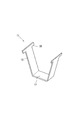
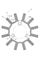
コア1は、円筒状のヨーク9、および、ヨーク9から外周側に突出してコイル6が巻かれる複数のティース10を具備する。また、コア1の素材となる鋼板11は、プレスによる打ち抜き後の材料11aに曲げ加工を施すことで、断面略U字を呈するものとして設けられる。すなわち、鋼板11は、底部12および底部12を挟む2つの辺部13を有するように折れ曲がっている。そして、鋼板11を複数枚積層してなる積層単位14を、複数、組み合わせることでコア1の骨格15が構成される(図2~図6等参照)。
ここで、積層単位14は、底部12が積み重なる底積層部17、辺部13が積み重なる2つの辺積層部18からなる。そして、骨格15は複数の積層単位14が環状に配置されて構成される。このとき、底積層部17は複数組み合わさって内周側で筒部分19を形成し、辺積層部18は外周側に突出する。
そして、骨格15の内、筒部分19がヨーク9の一部をなす。
また、周方向に隣り合う2つの積層単位14の組合せにおいて周方向に隣り合って当接する2つの辺積層部18により1つのティース10が構成される。すなわち、隣り合う2つの積層単位14の組合せにおいて、周方向一方側の積層単位14の2つの辺積層部18の内、周方向他方側に位置する辺積層部18と、周方向他方側の積層単位14の2つの辺積層部18の内、周方向一方側に位置する辺積層部18とが周方向に当接して1つのティース10をなす。
また、周方向に隣り合う2つの積層単位14の組合せにおいて周方向に隣り合って当接する2つの辺積層部18により1つのティース10が構成される。すなわち、隣り合う2つの積層単位14の組合せにおいて、周方向一方側の積層単位14の2つの辺積層部18の内、周方向他方側に位置する辺積層部18と、周方向他方側の積層単位14の2つの辺積層部18の内、周方向一方側に位置する辺積層部18とが周方向に当接して1つのティース10をなす。
なお、辺部13の先端には、骨格15やコア1として組み入れられたときに軸方向両端に伸びる鍔部20が設けられており、鍔部20も底部12や辺部13と同様に積み重なって鍔積層部21を構成する。ここで、鍔積層部21は、コア1と磁石7との磁束の受渡を強化するものであり、磁石7の軸方向長さに応じて軸方向への突出量が決められている。
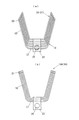
さらに、コア1によれば、一部の鋼板11は、底部12の一部を折り曲げてヨーク9の内周側に突出させることができる突出片23を有する変形鋼板24である。また、突出片23には、穴25が貫通している。ここで、突出片23は、図3に示すように、曲げ加工前の材料11aにおいて、長手方向に対し垂直に同一平面状に張り出す部分である。また、突出片23は2つ設けられており、2つの突出片23は、材料11aの幅方向両側に長手方向軸を対称軸として線対称をなす。
また、変形鋼板24が含まれる積層単位14Aでは最外周に変形鋼板24が配置され、突出片23は、ヨーク9の軸方向第一端側、第二端側に配置される。そして、突出片23は、ヨーク9の内周側に向かって垂直に折り曲げられてヨーク9の軸方向第一端側、第二端側でヨーク9の内周側に突出する。
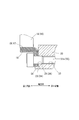
ここで、積層単位14Aは、120°の角度間隔で存在するように3ヶ所に組み入れられる。そして、2つの突出片23の間には円筒部材であるカラー27が配置され、カラー27の内周は穴25とともに貫通穴28を構成する(図1および図7参照。)。
ここで、積層単位14Aは、120°の角度間隔で存在するように3ヶ所に組み入れられる。そして、2つの突出片23の間には円筒部材であるカラー27が配置され、カラー27の内周は穴25とともに貫通穴28を構成する(図1および図7参照。)。
そして、ティース10にコイル6を巻いてステータ3を構成した後、ステータ3を内燃機関側の部材であるカバー30に嵌めてネジ締結する。ここで、突出片23の内周端は、コア1の内周端をなし、カバー30に設けられた取付部である円柱部31に外嵌めされる。そして、コア1を円柱部31に外嵌めした状態で貫通穴28にボルト32の軸部32aを通してネジ締結することで、ステータ3が車両に搭載される。なお、軸部32aは、カバー30に設けられたネジ穴33に螺合する。
〔実施例の効果〕
実施例のコア1によれば、素材となる鋼板11は、底部12および底部12を挟む2つの辺部13を有するように折れ曲がり、鋼板11を複数枚積層してなる積層単位14を、複数、組み合わせることで骨格15が構成される。また、骨格15は複数の積層単位14が環状に配置されて構成され、積層単位14の内の底部12が積み重なる底積層部17が複数組み合わさって内周側で筒部分19を形成し、辺積層部18が外周側に突出する。そして、骨格15の内、筒部分19がヨーク9をなすとともに、辺積層部18がティース10をなす。
実施例のコア1によれば、素材となる鋼板11は、底部12および底部12を挟む2つの辺部13を有するように折れ曲がり、鋼板11を複数枚積層してなる積層単位14を、複数、組み合わせることで骨格15が構成される。また、骨格15は複数の積層単位14が環状に配置されて構成され、積層単位14の内の底部12が積み重なる底積層部17が複数組み合わさって内周側で筒部分19を形成し、辺積層部18が外周側に突出する。そして、骨格15の内、筒部分19がヨーク9をなすとともに、辺積層部18がティース10をなす。
また、一部の鋼板11は、底部12の一部を折り曲げてヨーク9の内周側に突出させることができる突出片23を有する変形鋼板24であり、突出片23には、穴25が貫通している。
これにより、プレスによる打ち抜きにより発生する廃棄部分の一部を突出片23として変形鋼板24に含ませることができるので、廃棄部分を低減することができる。
これにより、プレスによる打ち抜きにより発生する廃棄部分の一部を突出片23として変形鋼板24に含ませることができるので、廃棄部分を低減することができる。
また、折り曲げ後の2つの突出片23の間には円筒部材であるカラー27が配置される。
これにより、突出片23を他部材へのネジ締結に利用する場合に、締結力に対して補強することができる。
さらに、突出片23の内周端は、内燃機関側の円柱部31に対して外嵌めされる。
これにより、ステータ3をいわゆるインローにより組み付けることを考えた場合、嵌合用に別部位を設けなくてもよい。
これにより、突出片23を他部材へのネジ締結に利用する場合に、締結力に対して補強することができる。
さらに、突出片23の内周端は、内燃機関側の円柱部31に対して外嵌めされる。
これにより、ステータ3をいわゆるインローにより組み付けることを考えた場合、嵌合用に別部位を設けなくてもよい。
〔変形例〕
コア1の構成は、実施例に限定されず、種々の変形例を考えることができる。
例えば、実施例のコア1によれば、変形鋼板24は2つの突出片23を有しており、2つの突出片23は、垂直に折り曲げられてヨーク9の軸方向第一端側、第二端側でヨーク9の内周側に突出するものであったが、変形鋼板24や突出片23の態様は実施例に限定されない。
コア1の構成は、実施例に限定されず、種々の変形例を考えることができる。
例えば、実施例のコア1によれば、変形鋼板24は2つの突出片23を有しており、2つの突出片23は、垂直に折り曲げられてヨーク9の軸方向第一端側、第二端側でヨーク9の内周側に突出するものであったが、変形鋼板24や突出片23の態様は実施例に限定されない。
例えば、変形鋼板24に突出片23を1つだけ設け、積層単位14Aに含まれる鋼板11を、全て、突出片23を1つだけ有する変形鋼板24とし、突出片23をヨーク9の軸方向第一端側に配置するとともにヨーク9の軸方向第一端側でヨーク9の内周側に突出させてもよい(図8参照。)。
また、実施例のコア1によれば、突出片23の内周端が内燃機関側の円柱部31に対して外嵌めされていたが、ステータ3と内燃機関側の部材とのインローの態様は実施例に限定されない。
例えば、カラー27の外周を円柱部31に対して外嵌めすることで、ステータ3と内燃機関側の部材とのインローを構成してもよい。
例えば、カラー27の外周を円柱部31に対して外嵌めすることで、ステータ3と内燃機関側の部材とのインローを構成してもよい。
さらに、実施例のコア1は、発電機2のステータコアとして利用されていたが、同期モータ、誘導モータおよびリラクタンスモータ等の電動機にコア1を利用してもよく、ロータコアとしてコア1を利用してもよい。
1 コア
2 発電機(回転電機)
9 ヨーク
10 ティース
11 鋼板
12 底部
13 辺部
14、14A 積層単位
15 骨格
17 底積層部
18 辺積層部
19 筒部分
23 突出片
24 変形鋼板
25 穴
2 発電機(回転電機)
9 ヨーク
10 ティース
11 鋼板
12 底部
13 辺部
14、14A 積層単位
15 骨格
17 底積層部
18 辺積層部
19 筒部分
23 突出片
24 変形鋼板
25 穴
Claims (6)
- 筒状のヨーク(9)、および、このヨーク(9)から外周側に突出する複数のティース(10)を具備する回転電機(2)のコア(1)において、
素材となる鋼板(11)は、底部(12)およびこの底部(12)を挟む2つの辺部(13)を有するように折れ曲がり、
前記鋼板(11)を複数枚積層してなる積層単位(14、14A)を、複数、組み合わせることで前記コア(1)の骨格(15)が構成され、
この骨格(15)では、前記積層単位(14、14A)の内の前記底部(12)が積み重なる底積層部(17)が複数組み合わさって内周側で筒部分(19)を形成するように、かつ、前記辺部(13)が積み重なる辺積層部(18)が外周側に突出するように、複数の前記積層単位(14、14A)が環状に配置され、
前記骨格(15)の内、前記筒部分(19)が前記ヨーク(9)の全部または一部をなすとともに、外周側に突出する前記辺積層部(18)が前記ティース(10)の全部または一部をなし、
一部の前記鋼板(11)は、前記底部(12)の一部を折り曲げて前記ヨーク(9)の内周側に突出させることができる突出片(23)を有する変形鋼板(24)であり、
前記突出片(23)には、穴(25)が貫通していることを特徴とする回転電機(2)のコア(1)。 - 請求項1に記載の回転電機(2)のコア(1)において、
前記変形鋼板(24)が含まれる前記積層単位(14、14A)では、この積層単位(14、14A)最外周に前記変形鋼板(24)が配置されることを特徴とする回転電機(2)のコア(1)。 - 請求項1または請求項2に記載の回転電機(2)のコア(1)において、
1つの前記変形鋼板(24)には、折り曲げ後の前記突出片(23)が前記ヨーク(9)の軸方向第一端側、第二端側の2か所で突出するように2つ設けられていることを特徴とする回転電機(2)のコア(1)。 - 請求項3に記載の回転電機(2)のコア(1)において、
折り曲げ後の2つの前記突出片(23)の間には、円筒部材(27)が配置されることを特徴とする回転電機(2)のコア(1)。 - 請求項1ないし請求項4の内のいずれか1つの回転電機(2)のコア(1)において、
前記コア(1)はステータコアであり、前記ティース(10)にコイル(6)が巻かれることを特徴とする回転電機(2)のコア(1)。 - 請求項5に記載の回転電機(2)のコア(1)において、
前記回転電機(2)は、内燃機関の出力により回転駆動される発電機(2)であり、
前記突出片(23)の内周端は、前記内燃機関側に設けられた取付部(31)に対して外嵌めされることを特徴とする回転電機(2)のコア(1)。
Priority Applications (1)
| Application Number | Priority Date | Filing Date | Title |
|---|---|---|---|
| CN201480055547.XA CN105612678B (zh) | 2013-10-08 | 2014-10-06 | 旋转电机的铁芯 |
Applications Claiming Priority (2)
| Application Number | Priority Date | Filing Date | Title |
|---|---|---|---|
| JP2013210670A JP2015076937A (ja) | 2013-10-08 | 2013-10-08 | 回転電機のコア |
| JP2013-210670 | 2013-10-08 |
Publications (1)
| Publication Number | Publication Date |
|---|---|
| WO2015053221A1 true WO2015053221A1 (ja) | 2015-04-16 |
Family
ID=52813037
Family Applications (1)
| Application Number | Title | Priority Date | Filing Date |
|---|---|---|---|
| PCT/JP2014/076694 Ceased WO2015053221A1 (ja) | 2013-10-08 | 2014-10-06 | 回転電機のコア |
Country Status (3)
| Country | Link |
|---|---|
| JP (1) | JP2015076937A (ja) |
| CN (1) | CN105612678B (ja) |
| WO (1) | WO2015053221A1 (ja) |
Families Citing this family (1)
| Publication number | Priority date | Publication date | Assignee | Title |
|---|---|---|---|---|
| JP7058531B2 (ja) * | 2018-03-26 | 2022-04-22 | 本田技研工業株式会社 | 曲げ装置及び方法 |
Citations (6)
| Publication number | Priority date | Publication date | Assignee | Title |
|---|---|---|---|---|
| JPS6219091Y2 (ja) * | 1979-06-28 | 1987-05-15 | ||
| JPH1080116A (ja) * | 1996-07-08 | 1998-03-24 | Toyota Motor Corp | リラクタンスモータ |
| JP2003244917A (ja) * | 2002-02-19 | 2003-08-29 | Denso Trim Kk | 磁石式発電機 |
| US20050194858A1 (en) * | 2004-03-03 | 2005-09-08 | Lg Electronics Inc. | Helical core and fabricating method thereof |
| JP2006087289A (ja) * | 2004-09-15 | 2006-03-30 | Lg Electronics Inc | モータのステータ及びその製造方法 |
| JP2010017002A (ja) * | 2008-07-04 | 2010-01-21 | Mazda Motor Corp | 回転電機のステータコア |
Family Cites Families (2)
| Publication number | Priority date | Publication date | Assignee | Title |
|---|---|---|---|---|
| JPH0654471A (ja) * | 1992-07-28 | 1994-02-25 | Sankyo Seiki Mfg Co Ltd | 回転電機の電機子 |
| AU4693099A (en) * | 1998-06-18 | 2000-01-05 | Allied-Signal Inc. | Amorphous metal stator for a radial-flux electric motor |
-
2013
- 2013-10-08 JP JP2013210670A patent/JP2015076937A/ja active Pending
-
2014
- 2014-10-06 WO PCT/JP2014/076694 patent/WO2015053221A1/ja not_active Ceased
- 2014-10-06 CN CN201480055547.XA patent/CN105612678B/zh not_active Expired - Fee Related
Patent Citations (6)
| Publication number | Priority date | Publication date | Assignee | Title |
|---|---|---|---|---|
| JPS6219091Y2 (ja) * | 1979-06-28 | 1987-05-15 | ||
| JPH1080116A (ja) * | 1996-07-08 | 1998-03-24 | Toyota Motor Corp | リラクタンスモータ |
| JP2003244917A (ja) * | 2002-02-19 | 2003-08-29 | Denso Trim Kk | 磁石式発電機 |
| US20050194858A1 (en) * | 2004-03-03 | 2005-09-08 | Lg Electronics Inc. | Helical core and fabricating method thereof |
| JP2006087289A (ja) * | 2004-09-15 | 2006-03-30 | Lg Electronics Inc | モータのステータ及びその製造方法 |
| JP2010017002A (ja) * | 2008-07-04 | 2010-01-21 | Mazda Motor Corp | 回転電機のステータコア |
Also Published As
| Publication number | Publication date |
|---|---|
| CN105612678A (zh) | 2016-05-25 |
| CN105612678B (zh) | 2018-03-13 |
| JP2015076937A (ja) | 2015-04-20 |
Similar Documents
| Publication | Publication Date | Title |
|---|---|---|
| JP6022077B2 (ja) | 回転電機用ロータ | |
| US20130285500A1 (en) | Rotor for a motor and a motor | |
| JP5656719B2 (ja) | 永久磁石型回転電機及び永久磁石型回転電機の製造方法 | |
| JP2015116022A (ja) | 回転電機ロータ | |
| US20170040849A1 (en) | A High Efficiency Electric Motor Stator Manufactured with Grain-Oriented Silicon Steel Sheets | |
| JP2010075027A (ja) | ステータコア及びモータ | |
| JP2012235652A (ja) | 回転子および回転電機 | |
| JP6147418B2 (ja) | 回転電機の固定子及びその製造方法 | |
| JP2015061374A (ja) | ステータ | |
| WO2021064883A1 (ja) | 回転電機 | |
| JP6136477B2 (ja) | 回転電機およびその製造方法 | |
| JP2009050116A (ja) | コンデンサ電動機とその製造方法 | |
| WO2015053221A1 (ja) | 回転電機のコア | |
| JP5471653B2 (ja) | 永久磁石式電動モータ | |
| JP2015119516A (ja) | ステータコア、ステータ、及びモータ | |
| JP6091409B2 (ja) | 回転子鉄心及び回転子鉄心の製造方法 | |
| JP6515322B2 (ja) | 回転電機の固定子 | |
| JP2011172335A (ja) | 電動機 | |
| JP5286121B2 (ja) | トロイダル巻線モータ | |
| JP2014204531A (ja) | モータ | |
| WO2015053229A1 (ja) | 回転電機のコア | |
| JP5977182B2 (ja) | モータ | |
| JP6100540B2 (ja) | モータ | |
| JP2015119515A (ja) | ステータコア、ステータ、モータ、及びステータコアの製造方法 | |
| JP2013179765A (ja) | 回転電気機械 |
Legal Events
| Date | Code | Title | Description |
|---|---|---|---|
| 121 | Ep: the epo has been informed by wipo that ep was designated in this application |
Ref document number: 14852116 Country of ref document: EP Kind code of ref document: A1 |
|
| NENP | Non-entry into the national phase |
Ref country code: DE |
|
| 122 | Ep: pct application non-entry in european phase |
Ref document number: 14852116 Country of ref document: EP Kind code of ref document: A1 |