WO2015053003A1 - ガスタービンの燃料噴射装置 - Google Patents
ガスタービンの燃料噴射装置 Download PDFInfo
- Publication number
- WO2015053003A1 WO2015053003A1 PCT/JP2014/072604 JP2014072604W WO2015053003A1 WO 2015053003 A1 WO2015053003 A1 WO 2015053003A1 JP 2014072604 W JP2014072604 W JP 2014072604W WO 2015053003 A1 WO2015053003 A1 WO 2015053003A1
- Authority
- WO
- WIPO (PCT)
- Prior art keywords
- gas
- injection device
- fuel
- fuel injection
- mixing chamber
- Prior art date
- Legal status (The legal status is an assumption and is not a legal conclusion. Google has not performed a legal analysis and makes no representation as to the accuracy of the status listed.)
- Ceased
Links
Images




Classifications
-
- F—MECHANICAL ENGINEERING; LIGHTING; HEATING; WEAPONS; BLASTING
- F23—COMBUSTION APPARATUS; COMBUSTION PROCESSES
- F23R—GENERATING COMBUSTION PRODUCTS OF HIGH PRESSURE OR HIGH VELOCITY, e.g. GAS-TURBINE COMBUSTION CHAMBERS
- F23R3/00—Continuous combustion chambers using liquid or gaseous fuel
- F23R3/28—Continuous combustion chambers using liquid or gaseous fuel characterised by the fuel supply
- F23R3/283—Attaching or cooling of fuel injecting means including supports for fuel injectors, stems, or lances
-
- F—MECHANICAL ENGINEERING; LIGHTING; HEATING; WEAPONS; BLASTING
- F02—COMBUSTION ENGINES; HOT-GAS OR COMBUSTION-PRODUCT ENGINE PLANTS
- F02C—GAS-TURBINE PLANTS; AIR INTAKES FOR JET-PROPULSION PLANTS; CONTROLLING FUEL SUPPLY IN AIR-BREATHING JET-PROPULSION PLANTS
- F02C3/00—Gas-turbine plants characterised by the use of combustion products as the working fluid
- F02C3/20—Gas-turbine plants characterised by the use of combustion products as the working fluid using a special fuel, oxidant, or dilution fluid to generate the combustion products
-
- F—MECHANICAL ENGINEERING; LIGHTING; HEATING; WEAPONS; BLASTING
- F02—COMBUSTION ENGINES; HOT-GAS OR COMBUSTION-PRODUCT ENGINE PLANTS
- F02C—GAS-TURBINE PLANTS; AIR INTAKES FOR JET-PROPULSION PLANTS; CONTROLLING FUEL SUPPLY IN AIR-BREATHING JET-PROPULSION PLANTS
- F02C3/00—Gas-turbine plants characterised by the use of combustion products as the working fluid
- F02C3/20—Gas-turbine plants characterised by the use of combustion products as the working fluid using a special fuel, oxidant, or dilution fluid to generate the combustion products
- F02C3/30—Adding water, steam or other fluids for influencing combustion, e.g. to obtain cleaner exhaust gases
-
- F—MECHANICAL ENGINEERING; LIGHTING; HEATING; WEAPONS; BLASTING
- F02—COMBUSTION ENGINES; HOT-GAS OR COMBUSTION-PRODUCT ENGINE PLANTS
- F02C—GAS-TURBINE PLANTS; AIR INTAKES FOR JET-PROPULSION PLANTS; CONTROLLING FUEL SUPPLY IN AIR-BREATHING JET-PROPULSION PLANTS
- F02C3/00—Gas-turbine plants characterised by the use of combustion products as the working fluid
- F02C3/20—Gas-turbine plants characterised by the use of combustion products as the working fluid using a special fuel, oxidant, or dilution fluid to generate the combustion products
- F02C3/30—Adding water, steam or other fluids for influencing combustion, e.g. to obtain cleaner exhaust gases
- F02C3/305—Increasing the power, speed, torque or efficiency of a gas turbine or the thrust of a turbojet engine by injecting or adding water, steam or other fluids
-
- F—MECHANICAL ENGINEERING; LIGHTING; HEATING; WEAPONS; BLASTING
- F02—COMBUSTION ENGINES; HOT-GAS OR COMBUSTION-PRODUCT ENGINE PLANTS
- F02C—GAS-TURBINE PLANTS; AIR INTAKES FOR JET-PROPULSION PLANTS; CONTROLLING FUEL SUPPLY IN AIR-BREATHING JET-PROPULSION PLANTS
- F02C7/00—Features, components parts, details or accessories, not provided for in, or of interest apart form groups F02C1/00 - F02C6/00; Air intakes for jet-propulsion plants
- F02C7/22—Fuel supply systems
-
- F—MECHANICAL ENGINEERING; LIGHTING; HEATING; WEAPONS; BLASTING
- F23—COMBUSTION APPARATUS; COMBUSTION PROCESSES
- F23C—METHODS OR APPARATUS FOR COMBUSTION USING FLUID FUEL OR SOLID FUEL SUSPENDED IN A CARRIER GAS OR AIR
- F23C1/00—Combustion apparatus specially adapted for combustion of two or more kinds of fuel simultaneously or alternately, at least one kind of fuel being either a fluid fuel or a solid fuel suspended in a carrier gas or air
- F23C1/04—Combustion apparatus specially adapted for combustion of two or more kinds of fuel simultaneously or alternately, at least one kind of fuel being either a fluid fuel or a solid fuel suspended in a carrier gas or air lump and gaseous fuel
-
- F—MECHANICAL ENGINEERING; LIGHTING; HEATING; WEAPONS; BLASTING
- F23—COMBUSTION APPARATUS; COMBUSTION PROCESSES
- F23D—BURNERS
- F23D11/00—Burners using a direct spraying action of liquid droplets or vaporised liquid into the combustion space
- F23D11/10—Burners using a direct spraying action of liquid droplets or vaporised liquid into the combustion space the spraying being induced by a gaseous medium, e.g. water vapour
-
- F—MECHANICAL ENGINEERING; LIGHTING; HEATING; WEAPONS; BLASTING
- F23—COMBUSTION APPARATUS; COMBUSTION PROCESSES
- F23D—BURNERS
- F23D11/00—Burners using a direct spraying action of liquid droplets or vaporised liquid into the combustion space
- F23D11/10—Burners using a direct spraying action of liquid droplets or vaporised liquid into the combustion space the spraying being induced by a gaseous medium, e.g. water vapour
- F23D11/16—Burners using a direct spraying action of liquid droplets or vaporised liquid into the combustion space the spraying being induced by a gaseous medium, e.g. water vapour in which an emulsion of water and fuel is sprayed
-
- F—MECHANICAL ENGINEERING; LIGHTING; HEATING; WEAPONS; BLASTING
- F23—COMBUSTION APPARATUS; COMBUSTION PROCESSES
- F23D—BURNERS
- F23D17/00—Burners for combustion simultaneously or alternately of gaseous or liquid or pulverulent fuel
- F23D17/002—Burners for combustion simultaneously or alternately of gaseous or liquid or pulverulent fuel gaseous or liquid fuel
-
- F—MECHANICAL ENGINEERING; LIGHTING; HEATING; WEAPONS; BLASTING
- F23—COMBUSTION APPARATUS; COMBUSTION PROCESSES
- F23L—SUPPLYING AIR OR NON-COMBUSTIBLE LIQUIDS OR GASES TO COMBUSTION APPARATUS IN GENERAL ; VALVES OR DAMPERS SPECIALLY ADAPTED FOR CONTROLLING AIR SUPPLY OR DRAUGHT IN COMBUSTION APPARATUS; INDUCING DRAUGHT IN COMBUSTION APPARATUS; TOPS FOR CHIMNEYS OR VENTILATING SHAFTS; TERMINALS FOR FLUES
- F23L7/00—Supplying non-combustible liquids or gases, other than air, to the fire, e.g. oxygen, steam
- F23L7/002—Supplying water
- F23L7/005—Evaporated water; Steam
-
- F—MECHANICAL ENGINEERING; LIGHTING; HEATING; WEAPONS; BLASTING
- F23—COMBUSTION APPARATUS; COMBUSTION PROCESSES
- F23R—GENERATING COMBUSTION PRODUCTS OF HIGH PRESSURE OR HIGH VELOCITY, e.g. GAS-TURBINE COMBUSTION CHAMBERS
- F23R3/00—Continuous combustion chambers using liquid or gaseous fuel
- F23R3/28—Continuous combustion chambers using liquid or gaseous fuel characterised by the fuel supply
-
- F—MECHANICAL ENGINEERING; LIGHTING; HEATING; WEAPONS; BLASTING
- F23—COMBUSTION APPARATUS; COMBUSTION PROCESSES
- F23R—GENERATING COMBUSTION PRODUCTS OF HIGH PRESSURE OR HIGH VELOCITY, e.g. GAS-TURBINE COMBUSTION CHAMBERS
- F23R3/00—Continuous combustion chambers using liquid or gaseous fuel
- F23R3/28—Continuous combustion chambers using liquid or gaseous fuel characterised by the fuel supply
- F23R3/36—Supply of different fuels
-
- F—MECHANICAL ENGINEERING; LIGHTING; HEATING; WEAPONS; BLASTING
- F23—COMBUSTION APPARATUS; COMBUSTION PROCESSES
- F23C—METHODS OR APPARATUS FOR COMBUSTION USING FLUID FUEL OR SOLID FUEL SUSPENDED IN A CARRIER GAS OR AIR
- F23C2900/00—Special features of, or arrangements for combustion apparatus using fluid fuels or solid fuels suspended in air; Combustion processes therefor
- F23C2900/9901—Combustion process using hydrogen, hydrogen peroxide water or brown gas as fuel
-
- F—MECHANICAL ENGINEERING; LIGHTING; HEATING; WEAPONS; BLASTING
- F23—COMBUSTION APPARATUS; COMBUSTION PROCESSES
- F23K—FEEDING FUEL TO COMBUSTION APPARATUS
- F23K2400/00—Pretreatment and supply of gaseous fuel
- F23K2400/10—Pretreatment
Definitions
- the present invention can efficiently reduce NOx in exhaust gas by premixing fuel gas such as hydrogen gas and water vapor so as to obtain a uniform concentration distribution before injection into the combustor.
- the present invention relates to a fuel injection device for a gas turbine.
- Patent Documents 1 to 3 In recent gas turbine systems, technologies for injecting fuel and water or water vapor into a combustor have been developed to reduce NOx in exhaust gas and increase the efficiency of the system (for example, Patent Documents 1 to 3).
- JP-A-6-66156 Special table 2010-535303 gazette JP-A-10-196401
- the liquid fuel, water vapor, and gas fuel from the liquid fuel nozzle, the water vapor nozzle, and the gas fuel nozzle are mixed for the first time in the combustion chamber after being injected into the combustor.
- the concentration distribution of fuel and water vapor is uneven, and NOx contained in the exhaust gas after combustion is not sufficiently reduced.
- the purpose is to reduce the flame temperature by injection of hydrogen fuel mixed with fine water droplets, but the specific structure is not disclosed and is included in the exhaust gas after combustion. The effective reduction of NOx is not expected.
- An object of the present invention is to provide a fuel injection device for a gas turbine that can make the concentration distribution of fuel gas and water vapor in a combustion chamber uniform with a simple structure and at low cost, and can effectively reduce NOx. There is to do.
- a fuel injection device for a gas turbine is a fuel injection device including a fuel nozzle that mixes fuel gas and water vapor and injects the gas into a combustion chamber.
- a nozzle housing having a first introduction passage for introducing fuel gas into the mixing chamber from a tangential direction, and a second introduction passage for introducing water vapor into the mixing chamber from a tangential direction. Steam is mixed by swirling around the axis of the mixing chamber.
- the fuel gas and the water vapor are mixed while swirling around the axis of the mixing chamber of the nozzle housing, the fuel gas and the water vapor are mixed in the mixing chamber as compared with the case where both are mixed without swirling.
- the fuel gas and the water vapor are sufficiently premixed as a result of being mixed over a long moving distance and time, and the concentration distribution of the fuel gas and the water vapor can be made uniform. Since the fuel gas and water vapor having a uniform concentration distribution are injected into the combustion chamber and burned, an effective reduction in NOx can be achieved.
- the steam can be effectively injected into the combustion field by premixing and injecting the fuel and the steam, the amount of water vapor used can be reduced, so that the efficiency of the entire gas turbine system is improved.
- an auxiliary facility such as a mixer for premixing is unnecessary, and the fuel injection device has a simple structure, so that it can be manufactured at low cost.
- the fuel injection device of the present invention includes a plurality of the first introduction passages and a plurality of the second introduction passages, and the first introduction passages and the second introduction passages are alternately arranged in the circumferential direction of the mixing chamber. Preferably it is. According to this configuration, the fuel gas from the first introduction passage and the water vapor from the second introduction passage can be uniformly introduced into the mixing chamber from the circumferential direction, and therefore, the concentration distribution of the fuel gas and water vapor in the mixing chamber Can be made more efficient.
- a single first supply path for supplying fuel gas to the plurality of first introduction passages, and a single second supply path for supplying water vapor to the plurality of second introduction passages It is preferable to provide. According to this configuration, since the plurality of first introduction passages and the plurality of second introduction passages are branched from the single first supply passage and the single second supply passage, respectively, the plurality of first introduction passages are provided. While providing the passage and the second introduction passage, the structure of the fuel injection device can be simplified and the cost can be reduced.
- the fuel injection device further includes a central member disposed on an axis of the nozzle housing, and the mixing chamber is formed on an outer periphery of the central member. According to this configuration, the fuel gas and water vapor introduced into the mixing chamber can be smoothly swung around the central member, and uniform mixing is promoted.
- a cooling passage for supplying cooling air to the outer surface of the central member is further provided. According to this configuration, the outer surface of the central member heated by the flame in the combustion chamber is cooled by the cooling air from the cooling passage, whereby thermal damage to the central member can be prevented.
- a gas injection portion is provided at a tip portion of the nozzle housing, and the gas injection portion includes a gas injection hole for injecting a mixed gas from the mixing chamber into a combustion chamber, and the central member. It is preferable to have an air injection hole for injecting air after cooling and a nozzle block for forming a tip gas header chamber upstream of the gas injection hole, and the cooling passage is formed in the nozzle block.
- the gas injection portion provided at the tip portion of the nozzle housing has a gas injection hole, an air injection hole, and a nozzle block, and the nozzle block has a compact structure in which the tip gas header chamber and the cooling passage are formed.
- the space required for installation in the gas turbine system can be reduced.
- the mixed gas is decelerated in the leading gas header chamber, and the mixing is further promoted.
- an intermediate gas header chamber is provided between the mixing chamber and the nozzle block, and a plurality of communication passages that communicate the intermediate gas header chamber and the tip gas header chamber are formed in the nozzle block.
- the mixed gas G is decelerated in the intermediate gas header chamber 44 and again decelerated in the tip gas header chamber 45 through the plurality of communication passages 47, so that mixing is further promoted.
- FIG. 7 is a sectional view taken along line VII-VII in FIG. 3. It is the graph which calculated
- FIG. 1 shows a gas turbine system to which a fuel injection device according to a preferred embodiment of the present invention is applied.
- a gas turbine system GT shown in the figure includes a compressor 1 that compresses air A, a combustor 2, a turbine 3, and a boiler 11.
- the boiler 11 generates water vapor using the exhaust gas EG from the turbine 3 as a heat source.
- a fuel injection device 4 is provided at the head of the combustor 2.
- a single first supply path 7 for supplying a fuel gas such as hydrogen gas H and water vapor from the boiler 11 are provided at the upstream end of the fuel nozzle 5 (FIG. 2) of the fuel injection device 4.
- a single second supply path 8 for supplying W is connected.
- the water vapor W is supplied in order to lower the temperature of the locally high-temperature flame in the combustion chamber 22 of the combustor 2 to reduce NOx.
- the hydrogen gas H supplied from the first supply path 7 and the water vapor W supplied from the second supply path 8 are premixed to generate the mixed gas G.
- hydrogen gas is most preferable as the fuel gas H, but natural gas may be used instead.
- the compressed air A supplied from the compressor 1 and the mixed gas G supplied from the fuel injection device 4 are combusted in the combustion chamber 22, and the high-temperature and high-pressure combustion gas CG generated thereby is supplied to the turbine 3.
- the turbine 3 is driven.
- the compressor 1 is driven by a turbine 3 via a rotating shaft 9, and this turbine 3 drives a load such as a generator PU.
- the upstream end of the second supply path 8 is connected to the boiler 11.
- the boiler 11 is installed in the exhaust passage 12 from the turbine 3, and the exhaust heat recovered from the exhaust gas EG is used to generate steam in the boiler 11. Used as a heat source.
- the exhaust gas EG that has passed through the boiler 11 passes through a silencer (not shown) and is then discharged to the outside.
- the boiler 11 is supplied with water from an external water supply source (not shown).
- the upstream end of the first supply path 7 is connected to the gas compressor 13.
- the gas compression device 13 compresses low-pressure hydrogen gas supplied from a fuel source such as a hydrogen gas cylinder (not shown) to form high-pressure hydrogen gas H, which is supplied to the fuel injection device 4.
- FIG. 2 shows the head of the combustor 2.
- the combustor 2 is a single can type, and a combustion cylinder 29 that forms a combustion chamber 22 is disposed inside a cylindrical housing 28.
- the top of the housing 28 is covered with a cover 17.
- the fuel injection device 4 is disposed concentrically with the combustion cylinder 29 and is attached to the cover 17, and a tip portion on the downstream side of the fuel nozzle 5 passes through the cover 17 and faces the combustion chamber 22.
- the first introduction pipe 25 that forms the first introduction passage 15 that supplies the fuel gas H and the second introduction pipe that forms the second introduction passage 16 that supplies the water vapor W to the base end portion that is upstream of the fuel nozzle 5. 26 is connected.
- An air passage 24 through which compressed air A compressed by the compressor 1 (FIG. 1) is sent into the combustion chamber 22 is formed on the outer periphery of the combustion cylinder 29.
- a part of the compressed air A flowing through the air passage 24 is introduced while swirling into the combustion chamber 22 via a swirler 27 disposed on the outer periphery of the air passage 24 at the top of the combustion cylinder 29 as indicated by an arrow. Is introduced into the combustion chamber 22 through a plurality of air holes 50 provided in the combustion cylinder 29.
- FIG. 3 shows the internal structure of the fuel injection device 4.
- the fuel nozzle 5 has a nozzle housing 31 having an annular mixing chamber 30 therein, and two first introduction passages 15, 15 are formed in a base end portion 31 a of the nozzle housing 31.
- the two second introduction passages 16 and 16 are connected.
- the two first introduction passages 15, 15 formed by the first introduction pipe 25 are arranged around the nozzle housing 31 so as to be separated from each other by 180 °.
- the two second introduction passages 16, 16 formed by the second introduction pipe 26 are also arranged around the nozzle housing 31 so as to be separated from each other by 180 °.
- the first introduction passages 15 and the second introduction passages 16 are alternately arranged in the circumferential direction of the nozzle housing 31.
- the first introduction passages 15 and the second introduction passages 16 introduce the fuel gas H and the water vapor W from the outer periphery of the nozzle housing 31 in the circumferential direction of the mixing chamber 30, that is, from the tangential direction into the mixing chamber 30. To do. As a result, the fuel gas H and the water vapor W are swirled around the axis of the mixing chamber 30 and mixed in the annular mixing chamber 30.
- a flange 33 is attached to the central portion of the nozzle housing 31 in the axial direction.
- the bolt 36 shown in FIG. 2 is inserted into the insertion hole 35 provided in the flange 33 and screwed into the cover 17, whereby the fuel injection device 4. Is supported by the cover 17.
- a round bar-shaped central member 38 is disposed on the axis C of the nozzle housing 31, and the mixing chamber 30 is formed on the outer periphery of the central member 38.
- the gas injection part 40 which injects the mixed gas G from the mixing chamber 30 to the combustion chamber 22 (FIG. 2) is provided in the front-end
- the gas injection unit 40 includes a gas injection hole 41 for injecting the mixed gas G, an air injection hole 42, and a nozzle block 43 that forms intermediate and leading end gas header chambers 44, 45 upstream of the gas injection hole 41. is doing.
- the upstream intermediate gas header chamber 44 stores the mixed gas G mixed in the mixing chamber 30.
- the intermediate gas header chamber 44 and the downstream end gas header chamber 45 are connected by a plurality of communication passages 47, and the gas injection holes 41 are in direct communication with the front end gas header chamber 45. Of the intermediate and tip gas header chambers 44 and 45, the upstream intermediate gas header chamber 44 may be omitted.
- the nozzle block 43 is formed with a cooling passage 48 for supplying cooling air to the outer surface of the central member 38.
- the cooling passage 48 communicates with the air passage 24 shown in FIG. 2, and a part of the compressed air A from the air passage 24 is taken in as cooling air, and after cooling the central member 38 in FIG. It is discharged from the hole 42 into the combustion chamber 22 (FIG. 2).
- a plurality of cooling passages 48 (for example, six) are formed in the nozzle block 43 at equal intervals in the tangential direction on the circumference of the center member 38.
- a plurality of communication passages 47, 47 are provided between 48.
- FIG. 5 shows a perspective view of the fuel injection device 4.
- a single first supply passage 7 is connected to two first introduction passages 15, 15, and fuel gas H is supplied to these first introduction passages 15, 15. Supply.
- a single second supply path 8 is connected to the second introduction passages 16 and 16, and the water vapor W is supplied to the second introduction passages 16 and 16.
- FIG. 6 shows a bottom view of the fuel injection device 4.
- gas injection holes 41 are concentrically provided in a plurality of rows at equal intervals.
- the fuel gas H is compressed by the gas compressor 13 and then introduced from the first supply passage 7 into the mixing chamber 30 via the first introduction passage 15 shown in FIG. Is done.
- the water vapor W generated in the boiler 11 of FIG. 1 is introduced into the mixing chamber 30 from the second supply path 8 through the second introduction path 16 shown in FIG.
- the mixing chamber 30 the fuel gas H and the water vapor W are mixed while swirling around the axis C of the mixing chamber 30.
- the mixing chamber 30 is compared with the case where both are mixed without swirling.
- the fuel gas H and the water vapor W are mixed over a long moving distance and time, so that the fuel gas H and the water vapor W are sufficiently premixed, and the concentration distribution of the fuel gas H and the water vapor W is uniform. Can be achieved.
- this fuel injection device 4 since the steam can be effectively injected into the combustion field by premixing and injecting the fuel and the steam, the amount of water vapor used can be reduced, so that the efficiency of the entire gas turbine system is improved. improves.
- an auxiliary facility such as a mixer for premixing is unnecessary, and the fuel injection device 4 has a simple structure, so that it can be manufactured at low cost.
- the mixed gas G enters the intermediate gas header chamber 44 from the mixing chamber 30, further enters the tip gas header chamber 45 through the plurality of communication passages 47, and passes through the gas injection holes 41 to the combustion chamber 22 of FIG. 2. Is injected into the inside.
- the mixed gas G is made uniform by deceleration in the intermediate and leading gas header chambers 44 and 45.
- the mixed gas G injected from the gas injection hole 41 is mixed with the compressed air A introduced into the combustion chamber 22 from the air passage 24 through the swirler 27 and the air introduction hole 50 of the second introduction passage 16 and combusts.
- the mixed gas G having a uniform concentration distribution burns, the amount of NOx contained in the exhaust gas discharged from the combustion chamber 22 is reduced.
- a plurality of first introduction passages 15 and a plurality of second introduction passages 16 are provided, and the first introduction passages 15 and the second introduction passages 16 are alternately arranged in the circumferential direction of the mixing chamber 30. Therefore, the fuel gas H from the first introduction passage 15 and the water vapor W from the second introduction passage 16 can be evenly introduced into the mixing chamber 30 from the circumferential direction. Therefore, the fuel gas in the mixing chamber 30 The concentration distribution of H and water vapor W can be made more uniform.
- the center member 38 disposed on the axis C of the nozzle housing 31 is provided, and the mixing chamber 30 is formed on the outer periphery of the center member 38, the fuel gas H and the water vapor W introduced into the mixing chamber 30 are supplied. It can be smoothly swung around the central member, and uniform mixing is promoted.
- the cooling passage 48 for supplying cooling air to the outer surface of the central member 38 is provided, the outer surface of the central member 38 heated by the flame in the combustion chamber 22 is the cooling air from the cooling passage 48. By being cooled, thermal damage to the central member 38 can be prevented.
- the gas injection portion 40 provided at the tip portion 31 b of the nozzle housing 31 includes a gas injection hole 41 for injecting the mixed gas G from the mixing chamber 30 into the combustion chamber 22, and a central member 38.
- the air injection hole 42 for injecting air after cooling the air and the nozzle block 43 for forming the tip gas header chamber 45 on the upstream side of the gas injection hole 41 have a cooling passage 48 formed in the nozzle block 43.
- the gas injection part 40 at the tip of the nozzle housing 31 has a gas injection hole 41, an air injection hole 42, and a nozzle block 43, and the nozzle block 43 is formed with a tip gas header chamber 45 and a cooling passage 48. It becomes a structure. Thereby, space saving of the arrangement
- an intermediate gas header chamber 44 is provided between the mixing chamber 30 and the nozzle block 43, and a plurality of communication units communicating the intermediate gas header chamber 44 and the tip gas header chamber 45 with the nozzle block 43 are provided.
- a passage 47 is formed.
- FIG. 8 shows the NOx reduction effect of the fuel injection device 4 of the present invention.
- FIG. 8 is a graph in which the NOx generation amount when the fuel injection device 4 according to the present invention is used and the NOx generation amount when the fuel injection device 4A of the comparative example is used are experimentally measured.
- FIG. 9 shows a longitudinal section of the fuel injection device 4A used in the experiment.
- This fuel injection device 4A corresponds to the device of Patent Document 1, and only the fuel gas H is injected from the fuel injection device 4A into the combustion chamber 22, and the water vapor W passes through the second introduction passage 16 penetrating the cover 17. Then, the gas is supplied from the water vapor nozzle 60 to the combustion chamber 22 through the swirler 27, and the fuel gas H and the water vapor W are mixed in the combustion chamber 22 for the first time.
- ⁇ indicates a case where natural gas and water vapor are burned in a conventional apparatus
- ⁇ indicates a case where hydrogen gas and water vapor are burned in a conventional apparatus
- ⁇ indicates a natural gas and water vapor in the apparatus of the present invention.
- the water / fuel ratio which is the weight ratio of water vapor to fuel gas, tends to increase as compared with the conventional apparatus. It was found that the generation of NOx was suppressed.
Landscapes
- Engineering & Computer Science (AREA)
- Chemical & Material Sciences (AREA)
- Combustion & Propulsion (AREA)
- Mechanical Engineering (AREA)
- General Engineering & Computer Science (AREA)
Abstract
燃焼室内の燃料ガスと水蒸気の濃度分布の均一化を簡単な構造で、かつ低コストで行え、効果的に低NOx化を図ることができるガスタービンの燃料噴射装置を提供する。このガスタービンの燃料噴射装置は、燃料ガス(H)と水蒸気(W)とを混合して燃焼室(22)に噴射する燃料噴射装置(4)であって、内部に混合室(30)を有するノズルハウジング(31)と、ノズルハウジング(31)に、その外周から混合室(30)の周方向に燃料ガス(H)を導入する第1導入通路(15)と、その外周から混合室(30)の周方向に水蒸気(W)を導入する第2導入通路(16)とを備え、混合室(30)内で燃料ガス(H)と水蒸気(W)を混合室(30)の軸心C回りに旋回させて混合する。
Description
本出願は、2013年10月11日出願の特願2013-213490の優先権を主張するものであり、その全体を参照により本願の一部をなすものとして引用する。
本発明は、水素ガスのような燃料ガスと水蒸気とを燃焼器内への噴射前に均一な濃度分布となるように予混合しておくことで排気ガス中のNOxを効率よく低減することができるガスタービンの燃料噴射装置に関する。
近年のガスタービンシステムにおいては、排気ガスの低NOx化およびシステムの高効率化を課題として、燃料と水または水蒸気を燃焼器に噴射する技術が開発されている(例えば特許文献1~3)。
しかしながら、特許文献1の燃料噴射装置の場合、液体燃料ノズル、水蒸気ノズルおよびガス燃料ノズルからの液体燃料、水蒸気およびガス燃料は、燃焼器への噴射後に燃焼室内で初めて混合されるので、燃焼室内における燃料と水蒸気との濃度分布が不均一なり、燃焼後の排気ガス中に含まれるNOxの低減も不十分である。特許文献2の燃料噴射装置の場合、微細な水滴を混入させた水素燃料の噴射による火炎温度の低減を目的としているが、具体的構造が開示されておらず、燃焼後の排気ガス中に含まれるNOxの効果的な低減は期待できない。さらに、特許文献3の燃料噴射装置の場合、液体燃料と水蒸気を予混合したのち、ノズルに供給し、燃料噴射圧の低減、ひいてはNOx排出量の低減を図る技術が示されているが、予混合のためのミキサーのような付帯設備が必要となる上,燃料として液体燃料を用いているので、燃焼室内の液体燃料と水蒸気の濃度分布の均一化が難しく、したがって、NOxの大幅な低減も難しい。
本発明の目的は、燃焼室内の燃料ガスと水蒸気の濃度分布の均一化を簡単な構造で、かつ低コストで行え、効果的に低NOx化を図ることができるガスタービンの燃料噴射装置を提供することにある。
前記目的を達成するために、本発明に係るガスタービンの燃料噴射装置は、燃料ガスと水蒸気とを混合して燃焼室に噴射する燃料ノズルを備えた燃料噴射装置であって、内部に混合室を有するノズルハウジングと、前記混合室内に接線方向から燃料ガスを導入する第1導入通路と、前記混合室内に接線方向から水蒸気を導入する第2導入通路とを備え、前記混合室内で燃料ガスと水蒸気を混合室の軸心回りに旋回させて混合する。
この構成によれば、燃料ガスおよび水蒸気は、ノズルハウジングの混合室の軸心回りに旋回しながら混合されるので、旋回させずに両者を混合する場合に比べ、混合室内で燃料ガスと水蒸気とが長い移動距離と時間をかけて混合される結果、燃料ガスと水蒸気との予混合が十分に行われ、燃料ガスと水蒸気の濃度分布の均一化が図れる。この燃料ガスと水蒸気の濃度分布が均一化されたものが燃焼室内に噴射されて燃焼するので、効果的な低NOx化を達成できる。また、燃料と蒸気を予混合して噴射することで燃焼場に効果的に蒸気を噴射できるから,使用する水蒸気量を低減できるので、ガスタービンシステム全体の効率が向上する。さらに、予混合のためのミキサーのような付帯設備が不要であり,燃料噴射装置も簡単な構造であるので、低コストで製作できる。
本発明の燃料噴射装置において、複数の前記第1導入通路および複数の前記第2導入通路を備え、前記第1導入通路と前記第2導入通路とが前記混合室の周方向に交互に並んでいることが好ましい。この構成によれば、第1導入通路からの燃料ガスと第2導入通路からの水蒸気を混合室に周方向から均等に導入することができ、したがって、混合室内での燃料ガスと水蒸気の濃度分布の均一化を一層効率的に行うことができる。
本発明の燃料噴射装置において、前記複数の第1導入通路に燃料ガスを供給する単一の第1供給路と、前記複数の第2導入通路に水蒸気を供給する単一の第2供給路とを備えていることが好ましい。この構成によれば、複数の第1導入通路および複数の第2導入通路がそれぞれ、単一の第1供給路、単一の第2供給路から分岐した構造となるので、複数の第1導入通路および第2導入通路を設けながらも、燃料噴射装置の構造を簡素化でき、コストも低減できる。
本発明の燃料噴射装置において、さらに、前記ノズルハウジングの軸心上に配置された中心部材を備え、前記中心部材の外周に前記混合室が形成されていることが好ましい。この構成によれば、混合室内に導入される燃料ガスおよび水蒸気を中心部材の回りに円滑に旋回させることができ、均一混合が促進される。
本発明の燃料噴射装置において、さらに、前記中心部材の外表面に冷却用空気を供給する冷却通路を備えていることが好ましい。この構成によれば、燃焼室内の火炎によって加熱される中心部材の外表面が冷却通路からの冷却用空気で冷却されることで、中心部材の熱損傷を防止できる。
本発明の燃料噴射装置において、前記ノズルハウジングの先端部にガス噴射部が設けられ、前記ガス噴射部は、前記混合室からの混合ガスを燃焼室に噴射するガス噴射孔と、前記中心部材を冷却した後の空気を噴射する空気噴射孔と、前記ガス噴射孔の上流側に先端ガスヘッダ室を形成するノズルブロックとを有し、前記ノズルブロックに前記冷却通路が形成されていることが好ましい。
この構成によれば、ノズルハウジングの先端部に設けられるガス噴射部がガス噴射孔と空気噴射孔とノズルブロックを有し、ノズルブロックに先端ガスヘッダ室と冷却通路が形成されたコンパクトな構造となるので、ガスタービンシステムに搭載する際の配置スペースの省スペース化が図られる。また、混合ガスが先端ガスヘッダ室内で減速して混合が一層促進される。
本発明の燃料噴射装置において、前記混合室と前記ノズルブロックとの間に中間ガスヘッダ室を有し、前記ノズルブロックに前記中間ガスヘッダ室と先端ガスヘッダ室とを連通する複数の連通路が形成されていることが好ましい。この構成によれば、混合ガスGが中間ガスヘッダ室44内で減速され、複数の連通路47を通って先端ガスヘッダ室45内で再び減速されるので、混合がより一層促進される。
請求の範囲および/または明細書および/または図面に開示された少なくとも2つの構成のどのような組合せも、本発明に含まれる。特に、請求の範囲の各請求項の2つ以上のどのような組合せも、本発明に含まれる。
本発明は、添付の図面を参考にした以下の好適な実施形態の説明から、より明瞭に理解されるであろう。しかしながら、実施形態および図面は単なる図示および説明のためのものであり、本発明の範囲を定めるために利用されるべきものではない。本発明の範囲は添付の請求の範囲によって定まる。添付図面において、複数の図面における同一の符号は、同一または相当する部分を示す。
本発明の好ましい実施形態にかかる燃料噴射装置を適用したガスタービンシステムを示す概略図である。
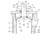
同燃料噴射装置を有する燃焼器の要部を示す縦断面図である。
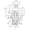
同燃料噴射装置の内部構造を示す縦断面図である。
同燃料噴射装置を示す概略横断面図である。
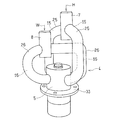
同燃料噴射装置の斜視図である。
同燃料噴射装置の底面図である。
図3のVII-VII線断面図である。
本発明による燃料噴射装置を用いた場合と、従来の燃料噴射装置を用いた場合のNOx発生量を実験により求めたグラフである。
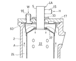
図8に示した実験に用いた比較例の燃料噴射装置を示す縦断面図である。
以下、本発明の好ましい実施形態について図面を参照しながら説明する。図1は本発明の好ましい実施形態にかかる燃料噴射装置を適用したガスタービンシステムを示す。同図に示すガスタービンシステムGTは、空気Aを圧縮する圧縮機1と、燃焼器2と、タービン3と、ボイラ11とを備えている。ボイラ11はタービン3からの排気ガスEGを熱源として水蒸気を発生する。
燃焼器2の頭部には燃料噴射装置4が設けられている。この燃料噴射装置4の燃料ノズル5(図2)の上流側である基端部には、水素ガスHのような燃料ガスを供給する単一の第1供給路7と、ボイラ11からの水蒸気Wを供給する単一の第2供給路8が接続されている。水蒸気Wは、燃焼器2の燃焼室22内の局所的に高温な火炎の温度を下げて低NOx化を図るために供給される。燃料噴射装置4では、第1供給路7から供給された水素ガスHと第2供給路8から供給された水蒸気Wとが予混合されて混合ガスGを生成する。なお、燃料ガスHとして水素ガスが最も好ましいが、これに代えて、天然ガスを用いることもできる。
圧縮機1から供給される圧縮空気Aと、燃料噴射装置4から供給される混合ガスGとを燃焼室22で燃焼させ、これにより発生する高温高圧の燃焼ガスCGをタービン3に供給し、このタービン3を駆動する。圧縮機1は回転軸9を介してタービン3により駆動され、このタービン3は発電機PUのような負荷を駆動する。
第2供給路8は、その上流側端がボイラ11に接続されており、このボイラ11はタービン3からの排気通路12に設置され、排気ガスEGから回収した排熱がボイラ11での蒸気生成の熱源に利用される。ボイラ11を通過した排気ガスEGは、図示しないサイレンサを通ったのち、外部に排出される。ボイラ11には、図示しない外部の給水源から水が供給される。
第1供給路7は、その上流側端がガス圧縮装置13に接続されている。このガス圧縮装置13により、図示しない水素ガスボンベのような燃料源から供給される低圧の水素ガスが圧縮されて高圧の水素ガスHとなって、燃料噴射装置4に供給される。
図2は燃焼器2の頭部を示す。同図に示すように、燃焼器2は単缶型であり、筒状のハウジング28の内側に燃焼室22を形成する燃焼筒29が配置されている。ハウジング28の頂部はカバー17により覆われている。燃料噴射装置4は、燃焼筒29と同心上に配置され、カバー17に取り付けられており、燃料ノズル5の下流側である先端部が、カバー17を貫通して燃焼室22に臨んでいる。燃料ノズル5の上流側である基端部に、燃料ガスHを供給する第1導入通路15を形成する第1導入管25および水蒸気Wを供給する第2導入通路16を形成する第2導入管26が接続されている。
燃焼筒29の外周には圧縮機1(図1)で圧縮された圧縮空気Aを燃焼室22内に送り込む空気通路24が形成されている。空気通路24を流れる圧縮空気Aの一部分は、矢印で示すように、燃焼筒29の頂部における空気通路24の外周に配置されたスワーラ27を経て燃焼室22に旋回しながら導入され、他の部分は、燃焼筒29に設けられた複数の空気孔50を通って燃焼室22に導入される。
図3は燃料噴射装置4の内部構造を示す。同図に示すように、燃料ノズル5は、内部に円環状の混合室30を有するノズルハウジング31を有し、このノズルハウジング31の基端部31aに、2つの第1導入通路15,15と、2つの第2導入通路16,16とが接続されている。図4に示すように、第1導入管25により形成された2つの第1導入通路15,15は、ノズルハウジング31の周りに180°離間して配置されている。第2導入管26により形成された2つの第2導入通路16,16もやはり、ノズルハウジング31の周りに180°離間して配置されている。第1導入通路15と第2導入通路16はノズルハウジング31の周方向に交互に並んでいる。各第1導入通路15および各第2導入通路16は、ノズルハウジング31の外周から前記混合室30の周方向に、つまり前記混合室30内に接線方向から、それぞれ燃料ガスHと水蒸気Wを導入する。これにより、円環状の混合室30内で燃料ガスHと水蒸気Wが混合室30の軸心回りに旋回されて混合される。
ノズルハウジング31の軸方向中央部にはフランジ33が取り付けられており、このフランジ33に設けた挿通孔35に図2に示すボルト36を挿通して、カバー17にねじ込むことにより、燃料噴射装置4がカバー17に支持される。ノズルハウジング31の軸心C上には丸棒状の中心部材38が配置されており、この中心部材38の外周に前記混合室30が形成されている。
ノズルハウジング31の先端部31bには、混合室30からの混合ガスGを燃焼室22(図2)に噴射するガス噴射部40が設けられている。このガス噴射部40は混合ガスGを噴射するガス噴射孔41と、空気噴射孔42と、前記ガス噴射孔41の上流側に中間および先端ガスヘッダ室44,45を形成するノズルブロック43とを有している。上流側の中間ガスヘッダ室44は混合室30で混合された混合ガスGを貯留する。中間ガスヘッダ室44と下流側の先端ガスヘッダ室45とは複数の連通路47で接続され、先端ガスヘッダ室45にはガス噴射孔41が直接、連通している。なお、前記中間および先端ガスヘッダ室44,45のうち、上流側の中間ガスヘッダ室44はなくてもよい。
さらに、ノズルブロック43には中心部材38の外表面に冷却用空気を供給する冷却通路48が形成されている。この冷却通路48は図2に示す空気通路24と連通しており、空気通路24からの圧縮空気Aの一部が冷却用空気として取り込まれ、図3の中心部材38を冷却した後、空気噴射孔42から燃焼室22(図2)に排出される。この冷却通路48は、図7に示すように、ノズルブロック43に、中心部材38の円周上の接線方向に等間隔で複数本(例えば6本)形成されており、隣接する冷却通路48,48の間に複数の連通路47,47が設けられている。
図5は燃料噴射装置4の斜視図を示す。同図に示すように、この燃料噴射装置4では、単一の第1供給路7が2つの第1導入通路15,15に接続されて、これら第1導入通路15,15に燃料ガスHを供給している。同様に単一の第2供給路8が第2導入通路16,16に接続されて、これら第2導入通路16,16に水蒸気Wを供給している。
図6は同燃料噴射装置4の底面図を示す。燃料ノズル5の中心部の空気噴射孔42の周囲に、ガス噴射孔41が同心円状に複数列、等間隔で設けられている。
つぎに、この燃料噴射装置の動作について説明する。ガスタービンの作動時、図1に示すように、燃料ガスHは、ガス圧縮装置13で圧縮されたのち、第1供給路7から図4に示す第1導入通路15を経て混合室30に導入される。一方、図1のボイラ11で生成された水蒸気Wは、第2供給路8から図4に示す第2導入通路16を経て混合室30に導入される。この混合室30において燃料ガスHと水蒸気Wとが混合室30の軸心C回りに旋回しながら混合される。このように、混合室30内で燃料ガスHと水蒸気Wを混合室30の軸心C回りに旋回させて混合するようにしたので、旋回させずに両者を混合する場合に比べ、混合室30内で燃料ガスHと水蒸気Wとが長い移動距離と時間をかけて混合される結果、燃料ガスHと水蒸気Wとの予混合が十分に行われ、燃料ガスHと水蒸気Wの濃度分布の均一化が図れる。
また、この燃料噴射装置4においては、燃料と蒸気を予混合して噴射することで燃焼場に効果的に蒸気を噴射できるから,使用する水蒸気量を低減できるので、ガスタービンシステム全体の効率が向上する。さらに、予混合のためのミキサーのような付帯設備が不要であり,燃料噴射装置4も簡単な構造であるので、低コストで製作できる。
図3に示すように、混合ガスGは、混合室30から中間ガスヘッダ室44に入り、さらに複数の連通路47を通って先端ガスヘッダ室45に入り、ガス噴射孔41から図2の燃焼室22内に噴射される。ここで、混合ガスGは、中間および先端ガスヘッダ室44,45内で減速による均一化が進む。ガス噴射孔41から噴射された混合ガスGは、空気通路24からスワーラ27および第2導入通路16の空気導入孔50から燃焼室22内に導入された圧縮空気Aに混合されて燃焼する。こうして、濃度分布が均一となった混合ガスGが燃焼するので、燃焼室22から排出される排気ガス中に含まれるNOx量が少なくなる。
また、図5に示すように、複数の第1導入通路15および複数の第2導入通路16を備え、第1導入通路15と第2導入通路16とが混合室30の周方向に交互に並んでいるので、第1導入通路15からの燃料ガスHと第2導入通路16からの水蒸気Wを混合室30に周方向から均等に導入することができ、したがって、混合室30内での燃料ガスHと水蒸気Wの濃度分布の均一化を一層効率的に行うことができる。
また、図3に示すように、複数の第1導入通路15に燃料ガスHを供給する単一の第1供給路7と、複数の第2導入通路16に水蒸気Wを供給する単一の第2供給路8とを備えているので、複数の第1導入通路15および複数の第2導入通路16がそれぞれ、単一の第1供給路7、単一の第2供給路8から分岐した構造となり、複数の第1導入通路15、第2導入通路16を設けながらも、燃料噴射装置4の構造を簡素化でき、コストも低減できる。
さらに、ノズルハウジング31の軸心C上に配置された中心部材38を備え、この中心部材38の外周に混合室30が形成したので、混合室30内に導入される燃料ガスHおよび水蒸気Wを中心部材の回りに円滑に旋回させることができ、均一混合が促進される。
さらに、中心部材38の外表面に冷却用空気を供給する冷却通路48を備えているので、燃焼室22内の火炎によって加熱される中心部材38の外表面が冷却通路48からの冷却用空気で冷却されることで、中心部材38の熱損傷を防止できる。
さらに、図3に示すように、ノズルハウジング31の先端部31bに設けられたガス噴射部40は、混合室30からの混合ガスGを燃焼室22に噴射するガス噴射孔41と、中心部材38を冷却した後の空気を噴射する空気噴射孔42と、ガス噴射孔41の上流側に先端ガスヘッダ室45を形成するノズルブロック43とを有し、このノズルブロック43に冷却通路48を形成している。したがって、ノズルハウジング31の先端部のガス噴射部40がガス噴射孔41と空気噴射孔42とノズルブロック43を有し、このノズルブロック43に先端ガスヘッダ室45と冷却通路48が形成されたコンパクトな構造となる。これにより、この燃料噴射装置4をガスタービンシステムに搭載する際の配置スペースの省スペース化が図られる。また、混合ガスGが先端ガスヘッダ室45内で減速して混合が一層促進される。
また、図3に示すように、混合室30とノズルブロック43との間に中間ガスヘッダ室44を有し、前記ノズルブロック43に前記中間ガスヘッダ室44と先端ガスヘッダ室45とを連通する複数の連通路47を形成している。これにより、混合ガスGが中間ガスヘッダ室44内で減速され、複数の連通路47を通って先端ガスヘッダ室45内で再び減速されるので、混合がより一層促進される。
本発明の燃料噴射装置4によるNOx低減効果を図8に示す。図8は本発明による燃料噴射装置4を用いた場合におけるNOx発生量と、比較例の燃料噴射装置4Aを用いた場合におけるNOx発生量を実験的に測定したグラフである。図9は実験に使用した燃料噴射装置4Aの縦断面を示す。この燃料噴射装置4Aは、特許文献1の装置に相当するもので、燃料ガスHのみが燃料噴射装置4Aから燃焼室22に噴射され、水蒸気Wはカバー17を貫通した第2導入通路16を通って水蒸気ノズル60からスワーラ27を経て燃焼室22に供給され、燃焼室22で燃料ガスHと水蒸気Wが初めて混合される。
図8において、▲印は従来の装置で天然ガスと水蒸気を燃焼させた場合、△印は従来の装置で水素ガスと水蒸気を燃焼させた場合、●印は本発明の装置で天然ガスと水蒸気を燃焼させた場合、○印は本発明の装置で水素ガスと水蒸気を燃焼させた場合のNOx発生量をそれぞれ示す。本発明の装置を用いた場合では、水蒸気を加える燃料が水素ガスか天然ガスであるにかかわりなく、傾向として水蒸気と燃料ガスの重量比である水燃比が増加するにともない、従来の装置よりもNOxの発生が抑制されていることが判った。
以上のとおり、図面を参照しながら好適な実施形態を説明したが、当業者であれば、本件明細書を見て、自明な範囲内で種々の変更および修正を容易に想定するであろう。したがって、そのような変更および修正は、請求の範囲から定まる発明の範囲内のものと解釈される。
GT…ガスタービンシステム
2…燃焼器
4…燃料噴射装置
5…燃料ノズル
7…第1供給路
8…第2供給路
15…第1連通路
16…第2連通路
22…燃焼室
25…第1導入管
26…第2導入管
30…混合室
31…ノズルハウジング
38…中心部材
40…ガス噴射部
41…ガス噴射孔
42…空気噴射孔
43…ノズルブロック
44…中間ガスヘッダ室
45…先端ガスヘッダ室
47…連通路
48…冷却通路
A…圧縮空気
C…混合室の軸心
EG…排気ガス
G…混合ガス
H…水素ガス(燃料ガス)
W…水蒸気
2…燃焼器
4…燃料噴射装置
5…燃料ノズル
7…第1供給路
8…第2供給路
15…第1連通路
16…第2連通路
22…燃焼室
25…第1導入管
26…第2導入管
30…混合室
31…ノズルハウジング
38…中心部材
40…ガス噴射部
41…ガス噴射孔
42…空気噴射孔
43…ノズルブロック
44…中間ガスヘッダ室
45…先端ガスヘッダ室
47…連通路
48…冷却通路
A…圧縮空気
C…混合室の軸心
EG…排気ガス
G…混合ガス
H…水素ガス(燃料ガス)
W…水蒸気
Claims (7)
- 燃料ガスと水蒸気とを混合して燃焼室に噴射する燃料噴射装置であって、
内部に混合室を有するノズルハウジングと、
前記混合室内に接線方向から燃料ガスを導入する第1導入通路と、
前記混合室内に接線方向から水蒸気を導入する第2導入通路とを備え、
前記混合室内で燃料ガスと水蒸気を混合室の軸心回りに旋回させて混合するガスタービンの燃料噴射装置。 - 請求項1に記載の燃料噴射装置において、複数の前記第1導入通路および複数の前記第2導入通路を備え、前記第1導入通路と前記第2導入通路とが前記混合室の周方向に交互に並んでいるガスタービンの燃料噴射装置。
- 請求項1に記載の燃料噴射装置において、前記複数の第1導入通路に燃料ガスを供給する単一の第1供給路と、前記複数の第2導入通路に水蒸気を供給する単一の第2供給路とを備えたガスタービンの燃料噴射装置。
- 請求項1ないし3のいずれかに記載の燃料噴射装置において、さらに、前記ノズルハウジングの軸心上に配置された中心部材を備え、前記中心部材の外周に前記混合室が形成されているガスタービンの燃料噴射装置。
- 請求項4に記載の燃料噴射装置において、さらに、前記中心部材の外表面に冷却用空気を供給する冷却通路を備えたガスタービンの燃料噴射装置。
- 請求項5に記載の燃料噴射装置において、前記ノズルハウジングの先端部にガス噴射部が設けられ、
前記ガス噴射部は、前記混合室からの混合ガスを燃焼室に噴射するガス噴射孔と、前記中心部材を冷却した後の空気を噴射する空気噴射孔と、前記ガス噴射孔の上流側に先端ガスヘッダ室を形成するノズルブロックとを有し、
前記ノズルブロックに前記冷却通路が形成されているガスタービンの燃料噴射装置。 - 請求項6に記載の燃料噴射装置において、前記混合室と前記ノズルブロックとの間に中間ガスヘッダ室を有し、前記ノズルブロックに前記中間ガスヘッダ室と先端ガスヘッダ室とを連通する複数の連通路が形成されているガスタービンの燃料噴射装置。
Priority Applications (2)
| Application Number | Priority Date | Filing Date | Title |
|---|---|---|---|
| DE112014004655.8T DE112014004655B4 (de) | 2013-10-11 | 2014-08-28 | Brennstoffeinspritzvorrichtung für eine Gasturbine |
| US15/051,993 US10443853B2 (en) | 2013-10-11 | 2016-02-24 | Fuel injection device for gas turbine |
Applications Claiming Priority (2)
| Application Number | Priority Date | Filing Date | Title |
|---|---|---|---|
| JP2013213490A JP6395363B2 (ja) | 2013-10-11 | 2013-10-11 | ガスタービンの燃料噴射装置 |
| JP2013-213490 | 2013-10-11 |
Related Child Applications (1)
| Application Number | Title | Priority Date | Filing Date |
|---|---|---|---|
| US15/051,993 Continuation US10443853B2 (en) | 2013-10-11 | 2016-02-24 | Fuel injection device for gas turbine |
Publications (1)
| Publication Number | Publication Date |
|---|---|
| WO2015053003A1 true WO2015053003A1 (ja) | 2015-04-16 |
Family
ID=52812823
Family Applications (1)
| Application Number | Title | Priority Date | Filing Date |
|---|---|---|---|
| PCT/JP2014/072604 Ceased WO2015053003A1 (ja) | 2013-10-11 | 2014-08-28 | ガスタービンの燃料噴射装置 |
Country Status (4)
| Country | Link |
|---|---|
| US (1) | US10443853B2 (ja) |
| JP (1) | JP6395363B2 (ja) |
| DE (1) | DE112014004655B4 (ja) |
| WO (1) | WO2015053003A1 (ja) |
Cited By (1)
| Publication number | Priority date | Publication date | Assignee | Title |
|---|---|---|---|---|
| CN107989716A (zh) * | 2018-01-02 | 2018-05-04 | 吉林大学 | 一种进气道内燃气喷射方向可变装置 |
Families Citing this family (5)
| Publication number | Priority date | Publication date | Assignee | Title |
|---|---|---|---|---|
| JP6327826B2 (ja) * | 2013-10-11 | 2018-05-23 | 川崎重工業株式会社 | ガスタービンの燃料噴射装置 |
| JP6602004B2 (ja) * | 2014-09-29 | 2019-11-06 | 川崎重工業株式会社 | 燃料噴射器及びガスタービン |
| SE2250307A1 (en) * | 2022-03-09 | 2023-09-10 | Phoenix Biopower Ip Services Ab | A method for the combustion of a fuel gas |
| DE102023106528A1 (de) * | 2023-03-15 | 2024-09-19 | Gottfried Wilhelm Leibniz Universität Hannover, Körperschaft des öffentlichen Rechts | Mehrstoffinjektor zur Verbrennung von Wasserstoff |
| US20240418127A1 (en) * | 2023-06-16 | 2024-12-19 | Raytheon Technologies Corporation | Gaseous fuel and liquid water injection for turbine engine |
Citations (6)
| Publication number | Priority date | Publication date | Assignee | Title |
|---|---|---|---|---|
| JPS50129708U (ja) * | 1974-04-10 | 1975-10-24 | ||
| JPS63150432A (ja) * | 1986-12-15 | 1988-06-23 | Mitsui Eng & Shipbuild Co Ltd | ガスタ−ビン |
| JP2000002420A (ja) * | 1998-06-16 | 2000-01-07 | Toyota Central Res & Dev Lab Inc | 多流体噴射式燃焼器 |
| JP2001041454A (ja) * | 1999-07-27 | 2001-02-13 | Ishikawajima Harima Heavy Ind Co Ltd | 非発兼用燃料噴射ノズル |
| JP2003279042A (ja) * | 2002-03-22 | 2003-10-02 | Ishikawajima Harima Heavy Ind Co Ltd | ガスタービンのガス混合機構 |
| JP2009287888A (ja) * | 2008-05-30 | 2009-12-10 | Ihi Corp | バーナ |
Family Cites Families (23)
| Publication number | Priority date | Publication date | Assignee | Title |
|---|---|---|---|---|
| US927561A (en) * | 1908-03-13 | 1909-07-13 | Arthur H Light | Oil-burner. |
| US1369688A (en) * | 1919-07-14 | 1921-02-22 | Ronald D Mayer | Oil-burner |
| US1381095A (en) * | 1920-03-27 | 1921-06-07 | Fletcher C Starr | Fuel-oil burner |
| US1591679A (en) * | 1921-01-15 | 1926-07-06 | Peoples Savings & Trust Compan | Process for the combustion of ash-containing fuels |
| US2566040A (en) * | 1947-09-26 | 1951-08-28 | New York Central Railroad Co | Fuel burning method and burner |
| US3758259A (en) * | 1971-11-26 | 1973-09-11 | J Voorheis | Methods for preparing fuels and also for thereafter feeding them into furnaces and burning them therein |
| JPS5146688B2 (ja) * | 1972-08-21 | 1976-12-10 | ||
| CA1159356A (en) * | 1979-10-25 | 1983-12-27 | Kurt Skoog | Method and device for producing microdroplets of fluid |
| JPH0666156B2 (ja) * | 1984-06-09 | 1994-08-24 | 松下電工株式会社 | 放電灯点灯装置 |
| US4614490A (en) * | 1985-04-01 | 1986-09-30 | Exxon Research And Engineering Co. | Method and apparatus for atomizing fuel |
| JP3174634B2 (ja) | 1992-08-11 | 2001-06-11 | 三菱重工業株式会社 | ガスタービンの燃料噴射装置 |
| US5628184A (en) * | 1993-02-03 | 1997-05-13 | Santos; Rolando R. | Apparatus for reducing the production of NOx in a gas turbine |
| US5479781A (en) * | 1993-09-02 | 1996-01-02 | General Electric Company | Low emission combustor having tangential lean direct injection |
| JPH10196401A (ja) * | 1997-01-13 | 1998-07-28 | Hitachi Ltd | コージェネレーションシステム |
| EP0924459A1 (de) * | 1997-12-17 | 1999-06-23 | Asea Brown Boveri AG | Verfahren und Vorrichtung zum Eindüsen eines Brennstoff-Flüssigkeitsgemisches in die Brennkammer eines Brenners |
| US6543231B2 (en) * | 2001-07-13 | 2003-04-08 | Pratt & Whitney Canada Corp | Cyclone combustor |
| US6715295B2 (en) * | 2002-05-22 | 2004-04-06 | Siemens Westinghouse Power Corporation | Gas turbine pilot burner water injection and method of operation |
| US6755359B2 (en) * | 2002-09-12 | 2004-06-29 | The Boeing Company | Fluid mixing injector and method |
| US20050106520A1 (en) * | 2003-09-05 | 2005-05-19 | Michael Cornwell | Device for stabilizing combustion in gas turbine engines |
| JP4509742B2 (ja) * | 2004-11-04 | 2010-07-21 | 株式会社日立製作所 | ガスタービン発電設備 |
| DE102005015152A1 (de) * | 2005-03-31 | 2006-10-05 | Alstom Technology Ltd. | Vormischbrenner für eine Gasturbinenbrennkammer |
| EP1990578A1 (de) | 2007-05-08 | 2008-11-12 | ALSTOM Technology Ltd | Gasturbine mit Wassereinspritzung |
| EP2058590B1 (de) * | 2007-11-09 | 2016-03-23 | Alstom Technology Ltd | Verfahren zum Betrieb eines Brenners |
-
2013
- 2013-10-11 JP JP2013213490A patent/JP6395363B2/ja active Active
-
2014
- 2014-08-28 WO PCT/JP2014/072604 patent/WO2015053003A1/ja not_active Ceased
- 2014-08-28 DE DE112014004655.8T patent/DE112014004655B4/de active Active
-
2016
- 2016-02-24 US US15/051,993 patent/US10443853B2/en active Active
Patent Citations (6)
| Publication number | Priority date | Publication date | Assignee | Title |
|---|---|---|---|---|
| JPS50129708U (ja) * | 1974-04-10 | 1975-10-24 | ||
| JPS63150432A (ja) * | 1986-12-15 | 1988-06-23 | Mitsui Eng & Shipbuild Co Ltd | ガスタ−ビン |
| JP2000002420A (ja) * | 1998-06-16 | 2000-01-07 | Toyota Central Res & Dev Lab Inc | 多流体噴射式燃焼器 |
| JP2001041454A (ja) * | 1999-07-27 | 2001-02-13 | Ishikawajima Harima Heavy Ind Co Ltd | 非発兼用燃料噴射ノズル |
| JP2003279042A (ja) * | 2002-03-22 | 2003-10-02 | Ishikawajima Harima Heavy Ind Co Ltd | ガスタービンのガス混合機構 |
| JP2009287888A (ja) * | 2008-05-30 | 2009-12-10 | Ihi Corp | バーナ |
Cited By (2)
| Publication number | Priority date | Publication date | Assignee | Title |
|---|---|---|---|---|
| CN107989716A (zh) * | 2018-01-02 | 2018-05-04 | 吉林大学 | 一种进气道内燃气喷射方向可变装置 |
| CN107989716B (zh) * | 2018-01-02 | 2023-12-15 | 吉林大学 | 一种进气道内燃气喷射方向可变装置 |
Also Published As
| Publication number | Publication date |
|---|---|
| US20160169523A1 (en) | 2016-06-16 |
| JP6395363B2 (ja) | 2018-09-26 |
| JP2015075313A (ja) | 2015-04-20 |
| DE112014004655B4 (de) | 2020-03-12 |
| DE112014004655T5 (de) | 2016-07-14 |
| US10443853B2 (en) | 2019-10-15 |
Similar Documents
| Publication | Publication Date | Title |
|---|---|---|
| JP6327826B2 (ja) | ガスタービンの燃料噴射装置 | |
| US8689559B2 (en) | Secondary combustion system for reducing the level of emissions generated by a turbomachine | |
| US9212822B2 (en) | Fuel injection assembly for use in turbine engines and method of assembling same | |
| US9599343B2 (en) | Fuel nozzle for use in a turbine engine and method of assembly | |
| US20170298817A1 (en) | Combustor and gas turbine engine | |
| KR102503321B1 (ko) | 연료 분사기, 연소기 및 가스 터빈 | |
| JP6395363B2 (ja) | ガスタービンの燃料噴射装置 | |
| JP6437018B2 (ja) | 排気再循環を伴う軸方向段構造燃焼システム | |
| US20150159875A1 (en) | Fuel injector with premix pilot nozzle | |
| US20140283498A1 (en) | Gas turbine system | |
| US11397006B2 (en) | Gas turbine combustor | |
| CN203907670U (zh) | 延迟贫喷射燃烧器组件及燃气涡轮发动机组件 | |
| CN104373960A (zh) | 具有稀释气体混合器的连续燃烧 | |
| WO2018181002A1 (ja) | 燃焼装置及びガスタービン | |
| US20130227928A1 (en) | Fuel nozzle assembly for use in turbine engines and method of assembling same | |
| JP2015090086A (ja) | ガスタービン燃焼器 | |
| US11015530B2 (en) | Combustor and gas turbine including the same | |
| CN103925617B (zh) | 涡轮机械构件的流套 |
Legal Events
| Date | Code | Title | Description |
|---|---|---|---|
| 121 | Ep: the epo has been informed by wipo that ep was designated in this application |
Ref document number: 14851485 Country of ref document: EP Kind code of ref document: A1 |
|
| WWE | Wipo information: entry into national phase |
Ref document number: 112014004655 Country of ref document: DE Ref document number: 1120140046558 Country of ref document: DE |
|
| 122 | Ep: pct application non-entry in european phase |
Ref document number: 14851485 Country of ref document: EP Kind code of ref document: A1 |