WO2015046239A1 - 照明装置及び表示装置 - Google Patents
照明装置及び表示装置 Download PDFInfo
- Publication number
- WO2015046239A1 WO2015046239A1 PCT/JP2014/075269 JP2014075269W WO2015046239A1 WO 2015046239 A1 WO2015046239 A1 WO 2015046239A1 JP 2014075269 W JP2014075269 W JP 2014075269W WO 2015046239 A1 WO2015046239 A1 WO 2015046239A1
- Authority
- WO
- WIPO (PCT)
- Prior art keywords
- guide plate
- light
- light guide
- light source
- source unit
- Prior art date
- Legal status (The legal status is an assumption and is not a legal conclusion. Google has not performed a legal analysis and makes no representation as to the accuracy of the status listed.)
- Ceased
Links
Images



Classifications
-
- G—PHYSICS
- G02—OPTICS
- G02B—OPTICAL ELEMENTS, SYSTEMS OR APPARATUS
- G02B6/00—Light guides; Structural details of arrangements comprising light guides and other optical elements, e.g. couplings
- G02B6/0001—Light guides; Structural details of arrangements comprising light guides and other optical elements, e.g. couplings specially adapted for lighting devices or systems
- G02B6/0011—Light guides; Structural details of arrangements comprising light guides and other optical elements, e.g. couplings specially adapted for lighting devices or systems the light guides being planar or of plate-like form
- G02B6/0081—Mechanical or electrical aspects of the light guide and light source in the lighting device peculiar to the adaptation to planar light guides, e.g. concerning packaging
- G02B6/0086—Positioning aspects
- G02B6/0088—Positioning aspects of the light guide or other optical sheets in the package
-
- G—PHYSICS
- G02—OPTICS
- G02B—OPTICAL ELEMENTS, SYSTEMS OR APPARATUS
- G02B6/00—Light guides; Structural details of arrangements comprising light guides and other optical elements, e.g. couplings
- G02B6/0001—Light guides; Structural details of arrangements comprising light guides and other optical elements, e.g. couplings specially adapted for lighting devices or systems
- G02B6/0011—Light guides; Structural details of arrangements comprising light guides and other optical elements, e.g. couplings specially adapted for lighting devices or systems the light guides being planar or of plate-like form
- G02B6/0013—Means for improving the coupling-in of light from the light source into the light guide
- G02B6/0015—Means for improving the coupling-in of light from the light source into the light guide provided on the surface of the light guide or in the bulk of it
- G02B6/002—Means for improving the coupling-in of light from the light source into the light guide provided on the surface of the light guide or in the bulk of it by shaping at least a portion of the light guide, e.g. with collimating, focussing or diverging surfaces
-
- G—PHYSICS
- G02—OPTICS
- G02B—OPTICAL ELEMENTS, SYSTEMS OR APPARATUS
- G02B6/00—Light guides; Structural details of arrangements comprising light guides and other optical elements, e.g. couplings
- G02B6/0001—Light guides; Structural details of arrangements comprising light guides and other optical elements, e.g. couplings specially adapted for lighting devices or systems
- G02B6/0011—Light guides; Structural details of arrangements comprising light guides and other optical elements, e.g. couplings specially adapted for lighting devices or systems the light guides being planar or of plate-like form
- G02B6/0066—Light guides; Structural details of arrangements comprising light guides and other optical elements, e.g. couplings specially adapted for lighting devices or systems the light guides being planar or of plate-like form characterised by the light source being coupled to the light guide
- G02B6/0073—Light emitting diode [LED]
-
- G—PHYSICS
- G02—OPTICS
- G02B—OPTICAL ELEMENTS, SYSTEMS OR APPARATUS
- G02B6/00—Light guides; Structural details of arrangements comprising light guides and other optical elements, e.g. couplings
- G02B6/0001—Light guides; Structural details of arrangements comprising light guides and other optical elements, e.g. couplings specially adapted for lighting devices or systems
- G02B6/0011—Light guides; Structural details of arrangements comprising light guides and other optical elements, e.g. couplings specially adapted for lighting devices or systems the light guides being planar or of plate-like form
- G02B6/0081—Mechanical or electrical aspects of the light guide and light source in the lighting device peculiar to the adaptation to planar light guides, e.g. concerning packaging
- G02B6/0085—Means for removing heat created by the light source from the package
-
- G—PHYSICS
- G02—OPTICS
- G02B—OPTICAL ELEMENTS, SYSTEMS OR APPARATUS
- G02B6/00—Light guides; Structural details of arrangements comprising light guides and other optical elements, e.g. couplings
- G02B6/0001—Light guides; Structural details of arrangements comprising light guides and other optical elements, e.g. couplings specially adapted for lighting devices or systems
- G02B6/0011—Light guides; Structural details of arrangements comprising light guides and other optical elements, e.g. couplings specially adapted for lighting devices or systems the light guides being planar or of plate-like form
- G02B6/0081—Mechanical or electrical aspects of the light guide and light source in the lighting device peculiar to the adaptation to planar light guides, e.g. concerning packaging
- G02B6/0086—Positioning aspects
- G02B6/009—Positioning aspects of the light source in the package
Definitions
- the present invention relates to an illumination device and a display device that emit light emitted from a light source unit from one surface of a light guide plate.
- the liquid crystal display device includes a liquid crystal display panel and a backlight unit that illuminates the liquid crystal display panel from the back side of the liquid crystal display panel.
- a backlight unit that illuminates the liquid crystal display panel from the back side of the liquid crystal display panel.
- an edge light type backlight unit has been proposed (see Patent Document 1).
- the edge light type backlight unit includes a rectangular light guide plate disposed on the back side of the liquid crystal display panel via an optical sheet group, and a light source unit disposed opposite the lower end surface of the light guide plate.
- the light source unit is formed by mounting a plurality of LEDs spaced apart in the left-right direction on one surface of the LED substrate.
- the light emitted from the light source unit passes through the lower end surface of the light guide plate and enters the light guide plate.
- the light incident on the inside of the light guide plate is emitted from the front surface of the light guide plate.
- the light emitted from the front surface of the light guide plate is incident on the inside of the liquid crystal display panel after being diffused and condensed by the optical sheet group. If the backlight unit uniformly illuminates the liquid crystal display panel, the display area of the liquid crystal display panel is uniformly brightened.
- the distance between each LED and the light guide plate is made constant by bringing the lower part of the light guide plate into partial contact with the LED substrate.
- Such a display device can suppress variations in the separation distance between each LED and the light guide plate due to the positional deviation of the light guide plate.
- generates thermal expansion by the heat_generation
- the part near the high temperature part of the light source part in the peripheral part of the light guide plate is more likely to cause thermal expansion than the part near the low temperature part of the light source part. Therefore, the separation distance between the LED and the portion near the high temperature portion of the light source section at the peripheral portion of the light guide plate is shorter than the separation distance between the LED and the portion near the low temperature portion of the light source portion at the peripheral portion of the light guide plate.
- Patent Document 1 does not describe technical matters for suppressing variations in the separation distance between each LED and the light guide plate due to thermal expansion of the light guide plate.
- the present invention has been made in view of such circumstances, and a main object thereof is to provide an illuminating device and a display device capable of uniformly illuminating.
- An illuminating device includes: a light guide plate that emits light incident on the inside thereof from one surface; and a light source unit that is disposed so as to oppose the peripheral surface of the light guide plate.
- the separation distance between the light source part and the peripheral surface is the longest separation distance between the central part of the light source plate in the peripheral direction of the light guide plate and the part corresponding to the central part of the peripheral surface.
- the illumination device is characterized in that when the light source part is not emitting light, a part corresponding to the central part in the peripheral part of the light guide plate is concave.
- a separation distance between a central portion in the peripheral direction of the light source unit and a portion corresponding to the central portion in the peripheral surface is a central portion in the peripheral direction.
- the separation distance is longest, and the distance is shortened continuously or stepwise from the central portion toward both sides in the peripheral direction.
- a display device includes the illumination device according to the present invention and a display panel illuminated from the back side by the illumination device.
- the separation distance between the light source unit and the peripheral surface of the light guide plate is not uniform. More specifically, the separation distance between the central part of the light source part and the part corresponding to the central part of the light source part on the peripheral surface of the light guide plate is the longest.
- the central portion / both ends of the light source unit means the central portion / both ends of the light guide plate in the light source plate in the peripheral direction (hereinafter simply referred to as the peripheral direction).
- the light guide plate undergoes thermal expansion due to the heat generated when the light source emits light. Then, the peripheral surface of the light guide plate is closer to the light source unit than when the light guide plate is not thermally expanded.
- the temperature of the light source unit due to the heat generation of the light source unit is higher at the center of the light source unit than at both ends of the light source unit. For this reason, the part corresponding to the center part of the light source part in the surrounding surface of a light-guide plate tends to raise
- the portion that is farthest from the light source unit is when the light guide plate is thermally expanded (that is, when the lighting device is used). Closest to the light source. Therefore, the distance between the light source unit and the peripheral surface of the light guide plate becomes uniform when the lighting device is used. Therefore, the amount of incident light from the light source unit to the inside of the light guide plate is uniform in the peripheral direction. As a result, the illumination by the illumination device becomes uniform in the peripheral direction. In other words, in order to make the amount of light incident on the inside of the light guide plate uniform when using the lighting device, the distance between the light source unit and the light guide plate when the lighting device is not used is intentionally non-uniform in the peripheral direction. Has been.
- the illumination device can make the amount of light incident on the inside of the light guide plate uniform in the peripheral direction with a simple configuration.
- the separation distance between the central portion of the light source portion and the portion corresponding to the central portion of the light source portion on the peripheral surface of the light guide plate is the longest separation distance related to the central portion in the peripheral direction, and the peripheral direction From the central portion to the both sides in the peripheral direction, the length is shortened continuously or stepwise.
- a light guide plate is particularly suitable when the amount of heat generated by the light source unit is symmetrical in the peripheral direction.
- the illumination device and the display device of the present invention when the light source unit is not emitting light, that is, when the light guide plate is not thermally expanded, the separation distance between the light source unit and the light guide plate is nonuniform in the peripheral direction.
- the amount of light incident on the inside can be made uniform in the peripheral direction.
- the illumination by an illuminating device can be made uniform in the peripheral direction.
- the brightness of the display area of the display panel can be made uniform in the peripheral direction. Therefore, the display quality of the display panel can be improved.
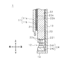
- Embodiment 1. 1 and 2 are longitudinal sectional views schematically showing the configuration of the display device 1 according to Embodiment 1 of the present invention. 1 and 2 show the vicinity of the lower side of a light guide plate 22 described later. 1 shows the left end portion or the right end portion of the light guide plate 22, and FIG. 2 shows the center portion of the light guide plate 22 in the left-right direction.
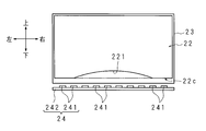
- FIG. 3 is a front view schematically showing the positional relationship between the light guide plate 22 and the light source unit 24 included in the backlight unit 12 as the illumination device according to Embodiment 1 of the present invention.
- the display device 1 is configured as, for example, a television receiver, an electronic signboard, or a monitor for a personal computer. First, the configuration of the display device 1 will be described.
- the display device 1 accommodates the display panel 11, the backlight unit (illumination device) 12, the backlight chassis 13, the heat sink 14, and these with the display area on the front surface 11 a of the display panel 11 exposed.
- a cabinet is provided.
- the display panel 11 is a liquid crystal display panel.
- the display panel 11 has a rectangular shape and is arranged in a vertical posture.
- the display panel 11 has a glass substrate on the front surface 11a side and a glass substrate on the back surface 11b side. Liquid crystal is sealed between the two glass substrates.
- the light transmittance of the display panel 11 changes according to the voltage applied to the liquid crystal of the display panel 11.
- a central portion in the surface direction of the display panel 11 is a rectangular display region, and a peripheral portion of the display panel 11 is a rectangular frame-shaped frame region.
- the backlight chassis 13 is formed in a dish shape that accommodates the backlight unit 12.
- the backlight chassis 13 has a back surface portion corresponding to the bottom surface of the plate and a peripheral surface portion (not shown) corresponding to the peripheral surface of the plate.
- the back surface portion of the backlight chassis 13 has a plate shape arranged in a vertical posture.
- the backlight unit 12 is supported between the display panel 11 and the back surface portion of the backlight chassis 13 by the backlight chassis 13 and a cabinet.
- the backlight unit 12 includes an optical sheet group 21, a light guide plate 22, a reflection sheet 23, and a light source unit 24.
- the optical sheet group 21 is formed by laminating a plurality of rectangular optical sheets.
- the optical sheet group 21 is disposed in close contact with the central portion of the back surface 11 b of the display panel 11.
- the length of the optical sheet group 21 in the vertical and horizontal directions is longer than the vertical and horizontal directions of the display area of the display panel 11.
- the optical sheet group 21 covers the display area on the back surface 11 b of the display panel 11.
- Each optical sheet constituting the optical sheet group 21 has a light diffusing function or a light collecting function.
- the light guide plate 22 has a rectangular plate shape.
- the light guide plate 22 is made of, for example, acrylic resin.
- the length of the light guide plate 22 in the left-right direction (hereinafter referred to as the horizontal length) is larger than the horizontal length of the display panel 11.
- the length of the light guide plate 22 in the vertical direction (hereinafter referred to as the vertical length) is not constant.
- the vertical length of the light guide plate 22 has the shortest vertical length at the center portion in the left-right direction and the longest vertical length at both left and right ends. The shortest vertical length of the light guide plate 22 is longer than the vertical length of the display panel 11.
- the vertical length of the light guide plate 22 is continuously increased from the center portion in the left-right direction toward both left and right sides. That is, the left-right direction center part in the lower side part (peripheral part) of the light-guide plate 22 is made into the upward concave shape.
- the concave portion in the lower side portion of the light guide plate 22 is referred to as a concave portion 221.
- the peripheral shape of the concave portion 221 has a gentle mountain shape.
- the vertical length of the light guide plate 22 at the center in the left-right direction may be configured to increase stepwise from the center in the left-right direction toward the left and right sides.
- the peripheral shape of the recess 221 is not limited to a mountain shape, and may be a rectangular shape, a semi-oval shape, a triangular shape, or the like.
- the light guide plate 22 emits light incident on the inside of the light guide plate 22 from the front surface (one surface) 22a of the light guide plate 22 (that is, emits light).
- a plurality of reflecting portions are provided on the back surface 22 b of the light guide plate 22.
- the reflection portion is provided by silk printing, laser printing, shaping, or the like on the back surface 22b.
- the light incident on the reflecting part is reflected toward the front surface 22a.
- the light incident on the inside of the light guide plate 22 is reflected by the front surface 22a, the back surface 22b, or the reflecting portion of the light guide plate 22, and eventually passes through the front surface 22a and is emitted to the outside of the light guide plate 22.
- part of the light incident on the inside of the light guide plate 22 may pass through the back surface 22b (that is, light leakage occurs).
- the reflection sheet 23 has a rectangular shape whose vertical length and horizontal length are longer than the vertical length and horizontal length of the light guide plate 22.
- the horizontal length of the reflection sheet 23 is approximately the same as the horizontal length of the light source unit 24.
- the reflection sheet 23 is disposed in close contact with the back surface of the light guide plate 22 and completely covers the back surface 22 b of the light guide plate 22. Therefore, the light leakage from the back surface 22 b of the light guide plate 22 is reflected by the reflection sheet 23 and enters the light guide plate 22 again.
- a heat sink 14 is disposed below the light guide plate 22.
- the heat sink 14 is supported by the backlight chassis 13.
- the heat conducted to the heat sink 14 is discharged to the outside of the display device 1.
- a light source unit 24 is disposed on the heat sink 14.
- the light source unit 24 includes a plurality of LEDs 241, 241,.
- the LED board 242 has a rectangular flat plate shape that is long in the left-right direction.
- the LEDs 241, 241,... are equally mounted in a line in the left-right direction on the upper surface of the LED substrate 242.
- the lower end surface (circumferential surface) 22 c of the light guide plate 22 are disposed to face each other with an appropriate distance therebetween.
- the center portion / both end portions in the peripheral direction of the light guide plate 22 in the light source portion 24 are referred to as the center portion / both end portions of the light source portion 24.
- the central portion / both ends of the light source unit 24 are the central portion / left and right end portions of the light source unit 24 in the left-right direction (the longitudinal direction of the light source unit 24).
- LED 241, 241,... Exist on both sides in the left-right direction of the central portion of the light source unit 24. Therefore, the amount of heat generated at the center of the light source unit 24 is greater than the amount of heat generated at the left end (or right end) of the light source 24, and the temperature at the center of the light source 24 is equal to the left end (or right end) of the light source 24. Temperature). In other words, the temperature of the light source unit 24 is not uniform in the left-right direction. Further, the temperature of the light source unit 24 is symmetrical. The heat generated by the LEDs 241, 241,... Is conducted to the heat sink 14 through the LED substrate 242. Further, the heat generated by the LEDs 241, 241,... Is transmitted to the light guide plate 22 by radiation, convection, or conduction.
- the separation distance between the lower end surface 22c of the light guide plate 22 and the light source unit 24 is the center portion in the left-right direction on the lower end surface 22c of the light guide plate 22 (the portion corresponding to the central portion of the light source unit 24 on the peripheral surface of the light guide plate 22). 221) and the distance between the central portion of the light source unit 24 is the longest. More specifically, the separation distance related to the central portion in the left-right direction of the recess 221 is the longest, and the separation distance continuously decreases from the center portion in the left-right direction of the recess 221 toward the left and right sides.
- the light emitted from the light source unit 24 passes through the lower end surface 22 c of the light guide plate 22 and enters the light guide plate 22.
- the light incident on the inside of the light guide plate 22 is emitted from the front surface 22 a of the light guide plate 22.
- the light emitted from the light guide plate 22 passes through the back surface 11 b of the display panel 11 through the diffusion and condensing by the optical sheet group 21 and enters the display panel 11.
- the display panel 11 is illuminated from the back surface 11b side by the backlight unit 12.
- the light incident on the display panel 11 passes through the display panel 11 or is blocked from passing through the display panel 11.
- an image is displayed in the display area of the display panel 11.
- FIG. 4 is a front view schematically showing the positional relationship between the light guide plate 220 and the light source unit 24 included in the conventional backlight unit.
- the conventional backlight unit has substantially the same configuration as the backlight unit 12.
- the conventional backlight unit includes a rectangular light guide plate 220 instead of the light guide plate 22.
- the lateral length of the light guide plate 220 is equal to the lateral length of the light guide plate 22.
- the vertical length of the light guide plate 220 is constant.
- the vertical length of the light guide plate 220 is longer than the shortest length of the light guide plate 22 in the vertical direction and is equal to or shorter than the longest length.
- the luminance of surface light emission of the light guide plate 220 is increased by 10%.
- the distance from the light guide plate 220 to the light source unit 24 is correlated with the high / low brightness of the surface light emission of the light guide plate 220. That is, as the distance from the light source unit 24 to the light guide plate 220 is shorter (or farther), the amount of light incident on the inside of the light guide plate 220 increases (or decreases), and the luminance of surface light emission of the light guide plate 220 increases ( Lower).
- the temperature of the central portion of the light source unit 24 is higher than the temperature of the left end (or right end) of the light source unit 24.
- the temperature of the lower side of the light guide plate 220 rises due to the heat generated when the light source unit 24 emits light.
- the temperature of the central portion in the left-right direction at the lower side portion of the light guide plate 220 is higher than the temperatures of both the left and right end portions at the lower side portion of the light guide plate 220. Therefore, the central portion in the left-right direction at the lower side portion of the light guide plate 220 is more likely to thermally expand than the left and right end portions at the lower side portion of the light guide plate 220.
- the shape of the light guide plate 220 at the time of non-thermal expansion is indicated by a solid line
- the shape of the light guide plate 220 at the time of thermal expansion is indicated by a two-dot chain line.
- the amount of deformation due to thermal expansion at each of the left and right ends of the lower side of the light guide plate 220 is not shown in FIG.
- the lower side of the light guide plate 220 forms a straight line in the left-right direction. Therefore, the separation distance between the lower end surface of the light guide plate 220 and the light source unit 24 is constant.
- the lower side portion of the light guide plate 220 has a downward convex portion at the center in the left-right direction. Therefore, the separation distance between the lower end surface of the light guide plate 220 and the light source unit 24 becomes uneven in the left-right direction.
- the separation distance between the light source plate 24 and the central portion in the left-right direction on the lower end surface of the light guide plate 220 is shorter than the separation distance between the left and right end portions on the lower end surface of the light guide plate 220 and the light source unit 24. Therefore, with respect to the amount of light that enters the light guide plate 220 from the light source unit 24, the incident light amount related to the central portion in the left-right direction of the light guide plate 220 is greater than the incident light amount related to the left end portion (or right end portion) of the light guide plate 220. Many.
- the surface light emission of the light guide plate 220 becomes uneven in the left-right direction.
- the central portion of the light guide plate 220 in the left-right direction is bright and the left and right end portions are dark.
- the illumination by the conventional backlight unit becomes non-uniform in the left-right direction. Therefore, the brightness of the display area of the display panel 11 becomes uneven in the left-right direction.
- the temperature at the center of the light source unit 24 is higher than the temperature at the left end (or right end) of the light source 24. Therefore, the central portion in the left-right direction at the lower side portion of the light guide plate 22 is more likely to thermally expand than the left and right end portions at the lower side portion of the light guide plate 22.
- the shape of the light guide plate 22 at the time of non-thermal expansion / thermal expansion and the light incident from the light source unit 24 to the light guide plate 22 are indicated by solid lines / two-dot chain lines.
- the deformation amount due to the thermal expansion of each of the left and right end portions of the lower side portion of the light guide plate 22 is smaller than the deformation amount due to the thermal expansion of the central portion in the left and right direction at the lower side portion of the light guide plate 22. Absent.
- the lower side portion of the light guide plate 22 When the light guide plate 22 is not thermally expanded, the lower side portion of the light guide plate 22 has a recess 221. Therefore, the separation distance between the lower end surface 22c of the light guide plate 22 and the light source unit 24 is not uniform.
- the lower side portion of the light guide plate 22 forms a straight line in the left and right direction, with the expanded portion at the central portion in the left and right direction at the lower side portion of the light guide plate 22 complementing the concave portion 221. Therefore, the separation distance between the lower end surface 22c of the light guide plate 22 and the light source unit 24 is constant.
- the incident light amount related to the central portion in the left-right direction of the light guide plate 22 and the incident light amount related to the left end portion (or right end portion) of the light guide plate 22 It becomes the same level. In other words, the amount of light entering the light guide plate 22 is uniform in the left-right direction.
- the surface light emission of the light guide plate 22 becomes uniform in the left-right direction. Therefore, the illumination by the backlight unit 12 becomes uneven in the left-right direction. Accordingly, the display area of the display panel 11 is uniformly brightened in the left-right direction.
- the display device 1 including the backlight unit 12 as described above, since the display area of the display panel 11 is uniformly bright in the left-right direction, the image quality of the video displayed in the display area is improved. However, until the display device 1 starts to be used and the light guide plate 22 in the non-thermal expansion state receives heat generated by the light source unit 24 and completely expands, the lower end surface 22c of the light guide plate 22 and the light source unit 24 are used. The separation distance is non-uniform. Further, the thermally expanded light guide plate 22 contracts by natural cooling after the use of the display device 1 is finished. Therefore, the display device 1 is suitable for an application in which the light guide plate 22 is used continuously for a long time, or an application in which the light guide plate 22 is used intermittently at a time interval that does not significantly contract.
- the backlight unit 12 includes the light guide plate 220, instead of the LED substrate 242 of the light source unit 24, the LED substrate whose left-right direction central portion is curved downward, or the left-right direction central portion is both left and right end portions. You may provide the LED board etc. which were provided in the step shape located below rather.
- the left-right direction center part of the light guide plate 220 and the center part of the light source part 24 at the time of non-thermal expansion are relatively separated, and the left and right end parts of the light guide plate 220 and both end parts of the light source part 24 Therefore, the distance between the light guide plate 220 and the light source unit 24 during thermal expansion is constant, and the incident light amount from the light source unit 24 to the inside of the light guide plate 220 is made uniform in the horizontal direction. can do.
- such an LED substrate is not common.
- the arrangement space of the LED substrate increases in the vertical direction. Therefore, it is advantageous to use the light guide plate 22 as in the present embodiment.
- the light guide plate 22 is also bilaterally symmetric. Therefore, if the temperature of the light source unit 24 is asymmetrical, the light guide plate 22 may be asymmetrical.
- the light source unit 24 is disposed to face the lower end surface 22 c of the light guide plate 22.
- the backlight unit 12 is replaced with the lower end surface 22c of the light guide plate 22 or together with the light source unit 24 disposed opposite to the lower end surface 22c of the light guide plate 22, and the light source unit disposed opposite to the upper end surface of the light guide plate 22. 24 may be provided. In this case, what is necessary is just to provide what corresponds to the recessed part 221 in the upper side part of the light-guide plate 22.
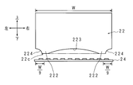
- FIG. FIG. 5 is a front view schematically showing the positional relationship between the light guide plate 22 and the light source unit 24 included in the backlight unit 12 according to Embodiment 2 of the present invention.
- FIG. 5 corresponds to FIG. 3 of the first embodiment.
- the reflection sheet 23 is not shown.
- the backlight unit 12 of the present embodiment has substantially the same configuration as the backlight unit 12 of the first embodiment.
- differences from the first embodiment will be described, and other parts corresponding to those of the first embodiment are denoted by the same reference numerals and description thereof will be omitted.
- the light guide plate 22 of the present embodiment does not have the concave portion 221.
- convex portions 222 and 222 are provided on the lower side of the light guide plate 22 at a distance ⁇ W / 9 ⁇ from both left and right ends.
- a concave portion 223 is provided between the convex portions 222 and 222, and concave portions 224 and 224 are provided on the left side and the right side of the convex portions 222 and 222.
- the horizontal center portion that is, the concave portion 223 of the lower end surface 22c of the light guide plate 22 and the central portion of the light source unit 24 are The separation distance and the separation distance between the left and right end portions (that is, the recesses 224 and 224) and the both end portions of the light source unit 24 on the lower end surface 22 c of the light guide plate 22 are both the longest.
- the surface light emission of the light guide plate 22 is relatively dark in the narrow range at the left and right ends, relatively bright in the wide range in the center in the left and right direction, and uniform in brightness.
- the brightness of the display area of the display panel 11 can be set as desired by the user.
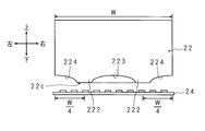
- FIG. FIG. 6 is a front view schematically showing the positional relationship between the light guide plate 22 and the light source unit 24 included in the backlight unit 12 according to Embodiment 3 of the present invention.
- FIG. 6 corresponds to FIG. 5 of the second embodiment.
- the backlight unit 12 of the present embodiment has substantially the same configuration as the backlight unit 12 of the second embodiment.
- differences from the second embodiment will be described, and other parts corresponding to the second embodiment will be denoted by the same reference numerals, and description thereof will be omitted.
- the arrangement positions of the convex portions 222 and 222 are positions at a distance ⁇ W / 9 ⁇ from the left and right end portions of the light guide plate 22, but in the case of the present embodiment, the convex portions 222 and 222 are arranged.
- the arrangement position is a position at a distance ⁇ W / 4 ⁇ from the left and right ends of the light guide plate 22.
- the surface light emission of the light guide plate 22 is relatively dark at the left and right ends, relatively bright at the center in the left and right direction, and uniform in brightness.
- the relatively dark range at the left and right ends is wider than that in the second embodiment, and the range in which the central portion in the left and right direction is relatively bright is narrower than that in the second embodiment.
- the surface light emission of the light guide plate 22 can be made uniform in a necessary range by appropriately designing the shape of the light guide plate 22. Therefore, the backlight unit 12 can uniformly illuminate a necessary range. As a result, the display device 1 can improve the image quality of the video displayed in the display area of the display panel 11 as desired by the user.
- FIG. 7 is a front view schematically showing the positional relationship between the light guide plate 22 and the light source unit 24 included in the backlight unit 12 according to Embodiment 4 of the present invention.
- FIG. 7 corresponds to FIG. 3 of the first embodiment.
- the reflection sheet 23 is not shown.
- the backlight unit 12 of the present embodiment has substantially the same configuration as the backlight unit 12 of the first embodiment.
- differences from the first embodiment will be described, and other parts corresponding to those of the first embodiment are denoted by the same reference numerals and description thereof will be omitted.
- the backlight unit 12 of the first embodiment is an edge light system in which a light source unit 24 is disposed below the light guide plate 22.
- the backlight unit 12 of the present embodiment is a side edge light system in which the light source portions 25, 25 are arranged on the left and right sides of the light guide plate 22.
- the backlight unit 12 is provided with a heat sink (not shown) that performs heat exhaustion related to the light source units 25 and 25 and the light source units 25 and 25 in place of the light source unit 24 and the heat sink 14 of the first embodiment.
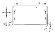
- the light guide plate 22 has recesses 225 and 225 instead of the recesses 221.
- Each of the light source units 25 includes LEDs 251, 251,... And an LED substrate 252 that are substantially similar to the LEDs 241, 241,.
- the LED substrate 252 has a rectangular shape with a vertical posture that is long in the vertical direction.
- the LED substrate 252 is arranged with one surface facing the side end surface (left end surface or right end surface) of the light guide plate 22.
- the LEDs 251, 251,... Are equally mounted in a line in the vertical direction on one surface of the LED substrate 252. ..
- the side end face of the light guide plate 22 are arranged to face each other with a suitable distance therebetween.
- the temperature of the light source unit 25 is not uniform in the vertical direction. Further, the temperature of the light source unit 25 is vertically symmetric.
- the lateral length of the light guide plate 22 during non-thermal expansion is not uniform in the vertical direction. For this reason, the central part in the vertical direction of the left side portion of the light guide plate 22 has a concave shape facing right. Similarly, the vertical central portion of the right side portion of the light guide plate 22 has a leftward concave shape.
- the concave portions 225 and 225 are concave portions on the left and right sides of the light guide plate 22.
- the backlight unit 12 and the display device 1 as described above exhibit the same functions and effects as the backlight unit 12 and the display device 1 of Embodiment 1 in the vertical direction. Due to the thermal expansion of the light guide plate 22 caused by heat generation during light emission of the light source portions 25, 25, the concave portions 225, 225 are lost from the left and right side portions of the light guide plate 22, and both left and right end surfaces of the light source portions 25, 25 and the light guide plate 22 The separation distance is constant. Accordingly, the amount of light entering the light guide plate 22 is uniform in the vertical direction. For this reason, the surface light emission of the light guide plate 22 becomes uniform in the vertical direction. Therefore, the illumination by the backlight unit 12 becomes uniform in the vertical direction. Accordingly, the display area of the display panel 11 is uniformly brightened in the vertical direction.
- the backlight unit 12 may include only the left (or right) light source unit 25. In this case, it is not necessary to provide the concave portion 225 on the right side (or left side) of the light guide plate 22.
- FIG. FIG. 8 is a front view schematically showing the positional relationship between the light guide plate 22 and the light source unit 24 included in the backlight unit 12 according to Embodiment 5 of the present invention.
- FIG. 8 corresponds to FIG. 3 of the first embodiment.
- the backlight unit 12 of the present embodiment has substantially the same configuration as the backlight unit 12 of the first embodiment.
- differences from the first embodiment will be described, and other parts corresponding to those of the first embodiment are denoted by the same reference numerals and description thereof will be omitted.
- the LED 241 does not exist on the left side of the light source unit 24 (or on the right side of the right end).
- LEDs 241, 241,... Exist on both sides in the left-right direction of the central portion of the light source unit 24. Therefore, the brightness at the center of the light source unit 24 is larger than the brightness at the left end (or right end) of the light source unit 24. In other words, the brightness of the light source unit 24 is not uniform in the left-right direction. Further, the brightness of the light source unit 24 is symmetrical.
- the light guide plate 22 of the present embodiment has a recess 221 even during thermal expansion.
- the concave portion 221 at the time of thermal expansion has a shallower shape than the concave portion 221 at the time of non-thermal expansion. That is, in the present embodiment, the light source plate 24 is far from the relatively hot and bright portion of the light source unit 24 to the lower end surface 22c of the light guide plate 22 regardless of whether the light guide plate 22 is thermally expanded or not.
- the relatively low temperature and dark part of the light guide plate 22 is close to the lower end surface 22c. Therefore, the amount of light entering the light guide plate 22 can be made uniform in the left-right direction.
- the illumination device is not limited to the backlight unit 12 incorporated in the display device 1.
- the lighting device may be configured as a backlight unit of a display unit included in a mobile phone or a portable information terminal device.
- the lighting device may be configured as a ceiling light or a wall-mounted lighting fixture.
- the light guide plate may be arranged in a horizontal posture with the front face downward.
- the display device 1 or the backlight unit 12 may include components that are not disclosed in the first to fifth embodiments.
- the constituent elements (technical features) disclosed in each embodiment can be combined with each other, and a new technical feature can be formed by the combination.
Landscapes
- Physics & Mathematics (AREA)
- General Physics & Mathematics (AREA)
- Optics & Photonics (AREA)
- Engineering & Computer Science (AREA)
- Microelectronics & Electronic Packaging (AREA)
- Planar Illumination Modules (AREA)
- Liquid Crystal (AREA)
Abstract
Description
以下では、液晶表示パネルが縦姿勢で配されている場合について説明する。
従来、エッジライト方式のバックライトユニットが提案されている(特許文献1参照)。エッジライト方式のバックライトユニットは、液晶表示パネルの背面側に、光学シート群を介して矩形状の導光板を配置し、導光板の下端面に対向して、光源部を配置してなる。光源部は、左右方向に離隔配置された複数個のLEDがLED基板の一面に実装されてなる。
バックライトユニットが液晶表示パネルを均一に照明すれば、液晶表示パネルの表示領域は均一に明るくなる。
特許文献1には、導光板の熱膨張に起因する各LEDと導光板との離隔距離のバラツキを抑制するための技術事項は記載されていない。
ここで、本明細書では、光源部の中央部/両端部とは、光源部における導光板の周縁方向(以下、単に周縁方向という)の中央部/両端部を意味する。
光源部の発熱に起因する光源部の温度は、光源部の両端部夫々よりも、光源部の中央部の方が高い。このため、導光板の周面における光源部の中央部に対応する部分は熱膨張を起こし易い。故に、導光板の周面における光源部の中央部に対応する部分が熱膨張によって光源部に接近する接近量は最大である。
つまり、照明装置の使用時における導光板の内部への入光量を周縁方向に均一にするために、照明装置の未使用時における光源部と導光板との離隔距離が敢えて周縁方向に不均一にされている。
つまり、導光板の非熱膨張時における導光板の形状を従来のものと異ならせることによって、導光板の内部への入光量を周縁方向に均一にすることができる。
導光板の周縁部の形状を従来のものと異ならせることは、例えば光源部の形状を従来のものと異ならせることによりも簡易である。換言すれば、照明装置は、簡易な構成で、導光板の内部への入光量を周縁方向に均一にすることができる。
図1及び図2は、本発明の実施の形態1に係る表示装置1の構成を模式的に示す縦断面図である。図1及び図2には、後述する導光板22の下辺部近傍が示されている。且つ、図1には導光板22の左端部又は右端部が示されており、図2には導光板22の左右方向中央部が示されている。
図3は、本発明の実施の形態1に係る照明装置としてのバックライトユニット12が備える導光板22及び光源部24の位置関係を模式的に示す正面図である。
まず、表示装置1の構成について説明する。
表示装置1は、表示パネル11、バックライトユニット(照明装置)12、バックライトシャーシ13、及びヒートシンク14、並びに、これらを表示パネル11の正面11aにおける表示領域を露出させた状態で収容する図示しないキャビネット等を備えている。
バックライトシャーシ13は、バックライトユニット12を収容する皿状になしてある。バックライトシャーシ13は、皿の底面に相当する背面部と、皿の周面に相当する図示しない周面部とを有する。バックライトシャーシ13の背面部は、縦姿勢に配された板状をなす。
バックライトユニット12は、光学シート群21、導光板22、反射シート23、及び光源部24を有する。
後述する従来の導光板220とは異なり、導光板22の上下方向の長さ(以下、縦長さという)は一定ではない。具体的には、導光板22の縦長さは、左右方向中心部分における縦長さが最短であり、左右両端部における縦長さが最長である。導光板22の最短の縦長さは、表示パネル11の縦長さ以上の長さである。導光板22の左右方向中央部では、左右方向中心部分から左右両側に向けて、導光板22の縦長さは連続的に長くなる。
つまり、導光板22の下辺部(周縁部)における左右方向中央部は、上向きの凹状になしてある。以下では、導光板22の下辺部における凹状の部分を、凹部221という。凹部221の周縁形状は、なだらかな山状をなす。
また、凹部221の周縁形状は、山状に限定されず、矩形状、半長円状、又は三角形状等でもよい。
反射シート23は、導光板22の背面に密着配置されて、導光板22の背面22bを完全に被覆している。従って、導光板22の背面22bからの漏光は、反射シート23にて反射し、再び導光板22の内部に入射する。
ヒートシンク14の上部には、光源部24が配されている。光源部24は、複数個のLED241,241,…とLED基板242とを備える。
LED基板242は、左右方向に長い横姿勢の矩形平板状になしてある。
以下では、光源部24における導光板22の周縁方向の中央部/両端部を、光源部24の中央部/両端部という。本実施の形態では、光源部24の中央部/両端部は、光源部24の左右方向(光源部24の長手方向)の中央部/左右両端部である。
LED241,241,…が発した熱は、LED基板242を介してヒートシンク14に伝導する。また、LED241,241,…が発した熱は、輻射、対流、又は伝導により、導光板22に伝達される。
光源部24が発した光は、導光板22の下端面22cを透過して導光板22の内部に入射する。
導光板22の内部に入射した光は、導光板22の正面22aから出射する。導光板22から出射した光は、光学シート群21による拡散及び集光等を経て、表示パネル11の背面11bを透過し、表示パネル11の内部に入射する。
図4は、従来のバックライトユニットが備える導光板220及び光源部24の位置関係を模式的に示す正面図である。
従来のバックライトユニットは、バックライトユニット12と略同様の構成である。ただし、従来のバックライトユニットは、導光板22に替えて、矩形状の導光板220を備えている。
導光板220の横長さは、導光板22の横長さに等しい。
導光板220の縦長さは一定である。導光板220の縦長さは、導光板22の上下方向の最短長さよりも長く、最長長さ以下の長さである。
つまり、光源部24から導光板220までの距離が近い(又は遠い)ほど、導光板220の内部へ入射する光の量が多く(又は少なく)なり、導光板220の面発光の輝度が高く(低く)なる。
光源部24の発光時の発熱によって導光板220の下辺部の温度が上昇する。このとき、導光板220の下辺部における左右方向中央部の温度は、導光板220の下辺部における左右両端部夫々の温度よりも高くなる。故に、導光板220の下辺部における左右方向中央部は、導光板220の下辺部における左右両端部夫々よりも熱膨張し易い。
図4には、非熱膨張時の導光板220の形状を実線で示し、熱膨張時の導光板220の形状を二点鎖線で示している。導光板220の下辺部における左右両端部夫々の熱膨張による変形量は、導光板220の下辺部における左右方向中央部の熱膨張による変形量よりも小さいため、図4には示していない。
一方、導光板220の熱膨張時には、導光板220の下辺部は、左右方向中央部にて下向きの凸部を生じる。故に、導光板220の下端面と光源部24との離隔距離は左右方向に不均一になる。具体的には、導光板220の下端面における左右方向中央部と光源部24との離隔距離が、導光板220の下端面における左右両端部夫々と光源部24との離隔距離よりも短くなる。
従って、光源部24から導光板220の内部へ入射する光の量に関し、導光板220の左右方向中央部に係る入光量は、導光板220の左端部(又は右端部)に係る入光量よりも多い。
導光板220の面発光に係る左右方向の不均一さが光学シート群21の拡散機能によって解消されない場合、従来のバックライトユニットによる照明は左右方向に不均一になる。従って、表示パネル11の表示領域の明るさが左右方向に不均一になる。
図1~図3には、非熱膨張時/熱膨張時の導光板22の形状と光源部24から導光板22への入光とを実線/二点鎖線で示している。導光板22の下辺部における左右両端部夫々の熱膨張による変形量は、導光板22の下辺部における左右方向中央部の熱膨張による変形量よりも小さいため、図1~図3には示していない。
一方、導光板22の熱膨張時には、導光板22の下辺部における左右方向中央部の膨張部分が凹部221を補完するかたちで、導光板22の下辺部は左右方向の直線状をなす。故に、導光板22の下端面22cと光源部24との離隔距離は一定になる。
従って、光源部24から導光板22の内部へ入射する光の量に関し、導光板22の左右方向中央部に係る入光量と、導光板22の左端部(又は右端部)に係る入光量とが同程度になる。換言すれば、導光板22の内部への入光量が左右方向に均一になる。
とはいえ、表示装置1が使用開始され、非熱膨張状態の導光板22が光源部24の発熱を受けて完全に膨張し終えるまでの間は、導光板22の下端面22cと光源部24との離隔距離は不均一である。また、熱膨張状態の導光板22は、表示装置1の使用終了後、自然冷却によって収縮する。従って、表示装置1は、長時間連続的に使用される用途、又は、導光板22が大幅に収縮しない程度の時間間隔で断続的に使用される用途等に適している。
しかしながら、このようなLED基板は一般的ではない。しかも、LED基板の配置スペースが上下方向に増大してしまう。従って、本実施の形態のように、導光板22を用いる方が有利である。
また、本実施の形態では、光源部24は、導光板22の下端面22cに対向配置されている。しかしながら、バックライトユニット12は、導光板22の下端面22cに替えて、又は導光板22の下端面22cに対向配置された光源部24と共に、導光板22の上端面に対向配置された光源部24を備えていてもよい。この場合、導光板22の上辺部に、凹部221に相当するものを設ければよい。
図5は、本発明の実施の形態2に係るバックライトユニット12が備える導光板22及び光源部24の位置関係を模式的に示す正面図である。図5は、実施の形態1の図3に対応する。ただし、反射シート23の図示は省略している。
本実施の形態のバックライトユニット12は、実施の形態1のバックライトユニット12と略同様の構成である。以下では、実施の形態1との差異について説明し、その他、実施の形態1に対応する部分には同一符号を付してそれらの説明を省略する。
このために、本実施の形態の導光板22は、実施の形態1の導光板22とは異なり、凹部221を有していない。
従って、非熱膨張時の導光板22の下端面22cと光源部24との離隔距離に関し、導光板22の下端面22cにおける左右方向中央部(即ち凹部223)と光源部24の中央部との離隔距離、及び、導光板22の下端面22cにおける左右両端部(即ち凹部224,224)と光源部24の両端部との離隔距離は、何れも最長である。
図6は、本発明の実施の形態3に係るバックライトユニット12が備える導光板22及び光源部24の位置関係を模式的に示す正面図である。図6は、実施の形態2の図5に対応する。
本実施の形態のバックライトユニット12は、実施の形態2のバックライトユニット12と略同様の構成である。以下では、実施の形態2との差異について説明し、その他、実施の形態2に対応する部分には同一符号を付してそれらの説明を省略する。
実施の形態2の場合、凸部222,222の配置位置は、導光板22の左右両端部から距離{W/9}の位置であるが、本実施の形態の場合、凸部222,222の配置位置は、導光板22の左右両端部から距離{W/4}の位置である。
図7は、本発明の実施の形態4に係るバックライトユニット12が備える導光板22及び光源部24の位置関係を模式的に示す正面図である。図7は、実施の形態1の図3に対応する。ただし、反射シート23の図示は省略している。
本実施の形態のバックライトユニット12は、実施の形態1のバックライトユニット12と略同様の構成である。以下では、実施の形態1との差異について説明し、その他、実施の形態1に対応する部分には同一符号を付してそれらの説明を省略する。
一方、本実施の形態のバックライトユニット12は、導光板22の左右両側方に光源部25,25が配されているサイドエッジライト方式である。
このため、バックライトユニット12は、実施の形態1の光源部24及びヒートシンク14に替えて、光源部25,25及び光源部25,25夫々に係る排熱を担う図示しないヒートシンクを備えている。
また、導光板22は、実施の形態1の導光板22とは異なり、凹部221に替えて、凹部225,225を有している。
LED基板252は、上下方向に長い縦姿勢の矩形状になしてある。LED基板252は、一面を導光板22の側端面(左側端面又は右側端面)に向けて配されている。
LED251,251,…は、LED基板252の一面にて上下方向に一列に等配実装してある。LED251,251,…と導光板22の側端面とは、適長離隔して対向配置されている。
光源部25の温度は上下方向に不均一である。また、光源部25の温度は上下対称である。
光源部25,25が発した光は、導光板22の左右両側端面を透過して導光板22の内部に入射する。
光源部25,25の発光時の発熱に起因する導光板22の熱膨張によって、導光板22の左右両辺部から凹部225,225が失われ、光源部25,25と導光板22の左右両側端面との離隔距離が一定になる。従って、導光板22の内部への入光量が、上下方向に均一になる。
このため、導光板22の面発光が上下方向に均一になる。故に、バックライトユニット12による照明は上下方向に均一になる。従って、表示パネル11の表示領域は上下方向に均一に明るくなる。
なお、バックライトユニット12は、左側(又は右側)の光源部25のみを備えている構成でもよい。この場合、導光板22の右側(又は左側)の凹部225を設ける必要はない。
図8は、本発明の実施の形態5に係るバックライトユニット12が備える導光板22及び光源部24の位置関係を模式的に示す正面図である。図8は、実施の形態1の図3に対応する。
本実施の形態のバックライトユニット12は、実施の形態1のバックライトユニット12と略同様の構成である。以下では、実施の形態1との差異について説明し、その他、実施の形態1に対応する部分には同一符号を付してそれらの説明を省略する。
つまり、本実施の形態においては、導光板22の熱膨張時/非熱膨張時を問わず、光源部24の比較的高温且つ明るい部分から導光板22の下端面22cまでは遠く、光源部24の比較的低温且つ暗い部分から導光板22の下端面22cまでは近い。故に、導光板22の内部への入光量を左右方向に均一にすることができる。
また、本発明の効果がある限りにおいて、表示装置1又はバックライトユニット12に、実施の形態1~5に開示されていない構成要素が含まれていてもよい。
各実施の形態に開示されている構成要件(技術的特徴)はお互いに組み合わせ可能であり、組み合わせによって新しい技術的特徴を形成することができる。
11 表示パネル
12 バックライトユニット(照明装置)
22 導光板
24,25 光源部
Claims (4)
- 内部に入射した光を一面から出射させる導光板と、
該導光板の周面に対向配置されている光源部と
を備える照明装置において、
前記光源部の非発光時には、前記光源部と前記周面との離隔距離は、前記光源部の前記導光板の周縁方向の中央部と前記周面における前記中央部に対応する部分との離隔距離が最長であることを特徴とする照明装置。 - 前記光源部の非発光時には、前記導光板の周縁部における前記中央部に対応する部分は凹状であることを特
徴とする請求項1に記載の照明装置。 - 前記光源部の非発光時には、前記光源部の前記周縁方向の中央部と前記周面における前記中央部に対応する部分との離隔距離は、前記周縁方向の中心部分に係る離隔距離が最長であり、該中心部分から前記周縁方向の両側に向けて連続的に又は段階的に短くなるようにしてあることを特徴とする請求項1又は2に記載の照明装置。
- 請求項1から3の何れかひとつに記載の照明装置と、
該照明装置によって背面側から照明される表示パネルと
を備えることを特徴とする表示装置。
Priority Applications (3)
| Application Number | Priority Date | Filing Date | Title |
|---|---|---|---|
| JP2015539256A JP6343616B2 (ja) | 2013-09-25 | 2014-09-24 | 照明装置及び表示装置 |
| CN201480053010.XA CN105579768B (zh) | 2013-09-25 | 2014-09-24 | 照明装置以及显示装置 |
| US15/023,963 US9874681B2 (en) | 2013-09-25 | 2014-09-24 | Illumination device and display apparatus |
Applications Claiming Priority (2)
| Application Number | Priority Date | Filing Date | Title |
|---|---|---|---|
| JP2013198465 | 2013-09-25 | ||
| JP2013-198465 | 2013-09-25 |
Publications (1)
| Publication Number | Publication Date |
|---|---|
| WO2015046239A1 true WO2015046239A1 (ja) | 2015-04-02 |
Family
ID=52743374
Family Applications (1)
| Application Number | Title | Priority Date | Filing Date |
|---|---|---|---|
| PCT/JP2014/075269 Ceased WO2015046239A1 (ja) | 2013-09-25 | 2014-09-24 | 照明装置及び表示装置 |
Country Status (4)
| Country | Link |
|---|---|
| US (1) | US9874681B2 (ja) |
| JP (1) | JP6343616B2 (ja) |
| CN (1) | CN105579768B (ja) |
| WO (1) | WO2015046239A1 (ja) |
Cited By (1)
| Publication number | Priority date | Publication date | Assignee | Title |
|---|---|---|---|---|
| JP2021060135A (ja) * | 2019-10-03 | 2021-04-15 | フクシマガリレイ株式会社 | 貯蔵庫 |
Families Citing this family (2)
| Publication number | Priority date | Publication date | Assignee | Title |
|---|---|---|---|---|
| US10962701B2 (en) * | 2019-04-04 | 2021-03-30 | S.V.V. Technology Innovations, Inc. | Wide-area solid-state illumination devices and systems |
| CN117055261A (zh) * | 2023-08-30 | 2023-11-14 | 滁州惠科光电科技有限公司 | 背光模组及显示装置 |
Citations (3)
| Publication number | Priority date | Publication date | Assignee | Title |
|---|---|---|---|---|
| JP2009117349A (ja) * | 2007-10-19 | 2009-05-28 | Fujifilm Corp | 面状照明装置 |
| JP2011192490A (ja) * | 2010-03-12 | 2011-09-29 | Omron Corp | 導光板 |
| WO2013136661A1 (ja) * | 2012-03-12 | 2013-09-19 | 日本電気株式会社 | 表示装置及び携帯端末装置 |
Family Cites Families (11)
| Publication number | Priority date | Publication date | Assignee | Title |
|---|---|---|---|---|
| JPH09282921A (ja) * | 1996-04-10 | 1997-10-31 | Canon Inc | バックライト装置及び該バックライト装置を備えた液晶表示装置 |
| JP4266551B2 (ja) * | 2000-12-14 | 2009-05-20 | 三菱レイヨン株式会社 | 面光源システムおよびそれに用いる光偏向素子 |
| TW558015U (en) * | 2002-12-06 | 2003-10-11 | Hon Hai Prec Ind Co Ltd | Backlight module |
| KR100710430B1 (ko) * | 2004-08-24 | 2007-04-24 | 삼성코닝 주식회사 | 면광원 장치 및 이를 갖는 백 라이트 유닛 |
| US20070139575A1 (en) * | 2005-12-16 | 2007-06-21 | Ceramate Technical Co., Ltd. | Display module for LCD |
| TW200727031A (en) * | 2006-01-03 | 2007-07-16 | Daxon Technology Inc | Light-emitting device and back light unit radiates with LEDs |
| KR100989219B1 (ko) * | 2006-06-30 | 2010-10-20 | 엘지디스플레이 주식회사 | 백라이트 어셈블리 및 이를 구비한 액정표시장치. |
| CN101256307A (zh) * | 2008-03-14 | 2008-09-03 | 上海广电光电子有限公司 | 直下式背光模组 |
| CN102112798B (zh) * | 2008-08-05 | 2013-05-01 | 夏普株式会社 | 面光源装置 |
| CN101749572B (zh) * | 2008-12-15 | 2012-10-10 | 鸿富锦精密工业(深圳)有限公司 | 发光模块 |
| JP2012237826A (ja) | 2011-05-10 | 2012-12-06 | Funai Electric Co Ltd | 液晶モジュール |
-
2014
- 2014-09-24 JP JP2015539256A patent/JP6343616B2/ja not_active Expired - Fee Related
- 2014-09-24 CN CN201480053010.XA patent/CN105579768B/zh not_active Expired - Fee Related
- 2014-09-24 WO PCT/JP2014/075269 patent/WO2015046239A1/ja not_active Ceased
- 2014-09-24 US US15/023,963 patent/US9874681B2/en not_active Expired - Fee Related
Patent Citations (3)
| Publication number | Priority date | Publication date | Assignee | Title |
|---|---|---|---|---|
| JP2009117349A (ja) * | 2007-10-19 | 2009-05-28 | Fujifilm Corp | 面状照明装置 |
| JP2011192490A (ja) * | 2010-03-12 | 2011-09-29 | Omron Corp | 導光板 |
| WO2013136661A1 (ja) * | 2012-03-12 | 2013-09-19 | 日本電気株式会社 | 表示装置及び携帯端末装置 |
Cited By (2)
| Publication number | Priority date | Publication date | Assignee | Title |
|---|---|---|---|---|
| JP2021060135A (ja) * | 2019-10-03 | 2021-04-15 | フクシマガリレイ株式会社 | 貯蔵庫 |
| JP7377667B2 (ja) | 2019-10-03 | 2023-11-10 | フクシマガリレイ株式会社 | 貯蔵庫 |
Also Published As
| Publication number | Publication date |
|---|---|
| JP6343616B2 (ja) | 2018-06-13 |
| US9874681B2 (en) | 2018-01-23 |
| CN105579768B (zh) | 2017-10-24 |
| CN105579768A (zh) | 2016-05-11 |
| JPWO2015046239A1 (ja) | 2017-03-09 |
| US20160238782A1 (en) | 2016-08-18 |
Similar Documents
| Publication | Publication Date | Title |
|---|---|---|
| CN103777382B (zh) | 弯曲显示装置 | |
| US8836894B2 (en) | Backlight unit and liquid crystal display device | |
| US10613271B2 (en) | Display device with heat dissipation plate | |
| US20160291397A1 (en) | Display device | |
| KR102089970B1 (ko) | 액정 디스플레이 장치 | |
| JP6343616B2 (ja) | 照明装置及び表示装置 | |
| TWI525370B (zh) | 液晶顯示裝置 | |
| JP2011180287A (ja) | 表示装置 | |
| KR101651888B1 (ko) | 백라이트 장치 | |
| JP5098778B2 (ja) | 照明装置、液晶表示装置及び電子機器 | |
| JP6329955B2 (ja) | 照明装置及び表示装置 | |
| WO2013189116A1 (zh) | 直下式的背光模块及包括其的液晶显示器 | |
| TWI345113B (en) | Backlight module and liquid crystal display device incorporating same | |
| JP6505121B2 (ja) | 光源装置及び表示装置 | |
| JP2013246891A (ja) | バックライトユニット及び液晶表示装置 | |
| CN202581151U (zh) | 分区背板装置及直下式背光扫描装置 | |
| CN104235662A (zh) | 灯条、背光源和显示装置 | |
| JP2015087411A (ja) | 表示装置 | |
| JP2011053270A (ja) | 液晶表示装置 | |
| KR101464655B1 (ko) | 영상디스플레이 구조 | |
| TWM358321U (en) | Edge lighting back light module | |
| JP2015210855A (ja) | 照明装置及び照明装置を備えた液晶表示装置 | |
| JP2015026416A (ja) | バックライト装置および液晶表示装置 | |
| WO2012067023A1 (ja) | バックライトユニットおよび液晶表示装置 | |
| CN103574402A (zh) | 背光装置、液晶模块以及液晶显示装置 |
Legal Events
| Date | Code | Title | Description |
|---|---|---|---|
| WWE | Wipo information: entry into national phase |
Ref document number: 201480053010.X Country of ref document: CN |
|
| 121 | Ep: the epo has been informed by wipo that ep was designated in this application |
Ref document number: 14848886 Country of ref document: EP Kind code of ref document: A1 |
|
| ENP | Entry into the national phase |
Ref document number: 2015539256 Country of ref document: JP Kind code of ref document: A |
|
| WWE | Wipo information: entry into national phase |
Ref document number: 15023963 Country of ref document: US |
|
| NENP | Non-entry into the national phase |
Ref country code: DE |
|
| 122 | Ep: pct application non-entry in european phase |
Ref document number: 14848886 Country of ref document: EP Kind code of ref document: A1 |