WO2015045542A1 - 内燃機関のバルブタイミング制御装置 - Google Patents
内燃機関のバルブタイミング制御装置 Download PDFInfo
- Publication number
- WO2015045542A1 WO2015045542A1 PCT/JP2014/067494 JP2014067494W WO2015045542A1 WO 2015045542 A1 WO2015045542 A1 WO 2015045542A1 JP 2014067494 W JP2014067494 W JP 2014067494W WO 2015045542 A1 WO2015045542 A1 WO 2015045542A1
- Authority
- WO
- WIPO (PCT)
- Prior art keywords
- timing control
- valve timing
- control device
- brush
- internal combustion
- Prior art date
- Legal status (The legal status is an assumption and is not a legal conclusion. Google has not performed a legal analysis and makes no representation as to the accuracy of the status listed.)
- Ceased
Links
Images




Classifications
-
- F—MECHANICAL ENGINEERING; LIGHTING; HEATING; WEAPONS; BLASTING
- F01—MACHINES OR ENGINES IN GENERAL; ENGINE PLANTS IN GENERAL; STEAM ENGINES
- F01L—CYCLICALLY OPERATING VALVES FOR MACHINES OR ENGINES
- F01L9/00—Valve-gear or valve arrangements actuated non-mechanically
- F01L9/20—Valve-gear or valve arrangements actuated non-mechanically by electric means
-
- F—MECHANICAL ENGINEERING; LIGHTING; HEATING; WEAPONS; BLASTING
- F01—MACHINES OR ENGINES IN GENERAL; ENGINE PLANTS IN GENERAL; STEAM ENGINES
- F01L—CYCLICALLY OPERATING VALVES FOR MACHINES OR ENGINES
- F01L1/00—Valve-gear or valve arrangements, e.g. lift-valve gear
- F01L1/34—Valve-gear or valve arrangements, e.g. lift-valve gear characterised by the provision of means for changing the timing of the valves without changing the duration of opening and without affecting the magnitude of the valve lift
- F01L1/344—Valve-gear or valve arrangements, e.g. lift-valve gear characterised by the provision of means for changing the timing of the valves without changing the duration of opening and without affecting the magnitude of the valve lift changing the angular relationship between crankshaft and camshaft, e.g. using helicoidal gear
- F01L1/352—Valve-gear or valve arrangements, e.g. lift-valve gear characterised by the provision of means for changing the timing of the valves without changing the duration of opening and without affecting the magnitude of the valve lift changing the angular relationship between crankshaft and camshaft, e.g. using helicoidal gear using bevel or epicyclic gear
-
- F—MECHANICAL ENGINEERING; LIGHTING; HEATING; WEAPONS; BLASTING
- F01—MACHINES OR ENGINES IN GENERAL; ENGINE PLANTS IN GENERAL; STEAM ENGINES
- F01L—CYCLICALLY OPERATING VALVES FOR MACHINES OR ENGINES
- F01L9/00—Valve-gear or valve arrangements actuated non-mechanically
- F01L9/40—Methods of operation thereof; Control of valve actuation, e.g. duration or lift
-
- H—ELECTRICITY
- H02—GENERATION; CONVERSION OR DISTRIBUTION OF ELECTRIC POWER
- H02K—DYNAMO-ELECTRIC MACHINES
- H02K5/00—Casings; Enclosures; Supports
- H02K5/04—Casings or enclosures characterised by the shape, form or construction thereof
- H02K5/14—Means for supporting or protecting brushes or brush holders
- H02K5/143—Means for supporting or protecting brushes or brush holders for cooperation with commutators
- H02K5/148—Slidably supported brushes
-
- H—ELECTRICITY
- H02—GENERATION; CONVERSION OR DISTRIBUTION OF ELECTRIC POWER
- H02K—DYNAMO-ELECTRIC MACHINES
- H02K5/00—Casings; Enclosures; Supports
- H02K5/04—Casings or enclosures characterised by the shape, form or construction thereof
- H02K5/22—Auxiliary parts of casings not covered by groups H02K5/06-H02K5/20, e.g. shaped to form connection boxes or terminal boxes
- H02K5/225—Terminal boxes or connection arrangements
-
- F—MECHANICAL ENGINEERING; LIGHTING; HEATING; WEAPONS; BLASTING
- F01—MACHINES OR ENGINES IN GENERAL; ENGINE PLANTS IN GENERAL; STEAM ENGINES
- F01L—CYCLICALLY OPERATING VALVES FOR MACHINES OR ENGINES
- F01L2250/00—Camshaft drives characterised by their transmission means
- F01L2250/02—Camshaft drives characterised by their transmission means the camshaft being driven by chains
-
- F—MECHANICAL ENGINEERING; LIGHTING; HEATING; WEAPONS; BLASTING
- F01—MACHINES OR ENGINES IN GENERAL; ENGINE PLANTS IN GENERAL; STEAM ENGINES
- F01L—CYCLICALLY OPERATING VALVES FOR MACHINES OR ENGINES
- F01L2301/00—Using particular materials
-
- F—MECHANICAL ENGINEERING; LIGHTING; HEATING; WEAPONS; BLASTING
- F01—MACHINES OR ENGINES IN GENERAL; ENGINE PLANTS IN GENERAL; STEAM ENGINES
- F01L—CYCLICALLY OPERATING VALVES FOR MACHINES OR ENGINES
- F01L2810/00—Arrangements solving specific problems in relation with valve gears
- F01L2810/04—Reducing noise
-
- F—MECHANICAL ENGINEERING; LIGHTING; HEATING; WEAPONS; BLASTING
- F01—MACHINES OR ENGINES IN GENERAL; ENGINE PLANTS IN GENERAL; STEAM ENGINES
- F01L—CYCLICALLY OPERATING VALVES FOR MACHINES OR ENGINES
- F01L2820/00—Details on specific features characterising valve gear arrangements
- F01L2820/03—Auxiliary actuators
- F01L2820/032—Electric motors
-
- H—ELECTRICITY
- H02—GENERATION; CONVERSION OR DISTRIBUTION OF ELECTRIC POWER
- H02K—DYNAMO-ELECTRIC MACHINES
- H02K7/00—Arrangements for handling mechanical energy structurally associated with dynamo-electric machines, e.g. structural association with mechanical driving motors or auxiliary dynamo-electric machines
- H02K7/14—Structural association with mechanical loads, e.g. with hand-held machine tools or fans
Definitions
- the present invention relates to a valve timing control device for an internal combustion engine that variably controls the opening / closing timing of intake valves and exhaust valves, which are engine valves of the internal combustion engine, using an electric motor.
- a direct current (DC) motor using a brush as a current-carrying switching mechanism of a motor coil is employed as the electric motor applied to the generation of rotational force.
- a direct current (DC) motor a coil is wound around a rotor provided on the outer periphery of the motor shaft, and a permanent magnet is provided on the inner peripheral surface of the motor housing as a stator opposed to the outer periphery of the rotor.
- a brush of a direct current (DC) motor with a brush is referred to as a “first brush”.
- the motor shaft and the rotor are rotatably supported by a bearing such as a ball bearing.
- a mechanism comprising a slip ring and a brush (hereinafter referred to as “second brush”) is used. That is, with this configuration, the camshaft can be rotated relative to the timing sprocket via the speed reduction mechanism by the rotational force of the motor.
- Patent Document 2 and Patent Document 3 disclose a direct current (DC) motor with a brush to which a noise reduction component is connected, although the application target is a fuel pump.
- the valve timing control device described in Patent Document 1 unlike the fuel pump motor, power is supplied to the slip ring and the DC motor as means for supplying power to the brushed DC motor. Since the mechanism composed of the second brush to be supplied is used, the second brush and the conductor constituting the slip ring that moves relative to the second brush have a structure in which they slide in contact with each other. Accordingly, electromagnetic noise associated with discharge is generated between the second brush and the slip ring as well as between the first brush and the commutator of the motor unit. Therefore, in particular, in the valve timing control apparatus according to the present invention, the noise reduction component includes the electromagnetic noise accompanying the discharge generated between the first brush and the commutator of the motor unit. Between the second brush and the slip ring, noise must be effectively reduced against both electromagnetic noise accompanying discharge.
- valve timing control device for an internal combustion engine that variably controls the opening and closing timing of the intake valve and the exhaust valve, which are engine valves of the internal combustion engine, using an electric motor, the problems in the present invention and the prior art described above, It is necessary to prevent electromagnetic noise accompanying discharge between the brush of the motor and the commutator of the motor unit, and further between the second brush and the slip ring, from leaking to the outside of the device.
- valve timing control apparatus for an internal combustion engine it is important to effectively use a limited space in the engine room of the automobile, and it is important not to occupy the space unnecessarily. That is, it is an important issue to keep the volume occupied by the device itself small while effectively suppressing leakage of generated electromagnetic noise.
- valve timing control device is a device directly attached to the engine, countermeasures against vibration of the electromagnetic noise emission suppression means as a noise reduction component, and further, electronic components constituting the electromagnetic noise emission suppression means Therefore, it is important to consider the heat dissipation.
- the present invention has been made to solve the above-described problems in the prior art, and the object thereof is to prevent noise leakage to the outside of the device, particularly in a valve timing control device for an internal combustion engine. It is an object of the present invention to provide a valve timing control device that can be suppressed and can improve the reliability without increasing the volume occupied by the device more than necessary.
- the present invention adopts, for example, the configuration described in the claims. That is, a driving rotating body (timing sprocket 111) to which a rotating force is transmitted from the crankshaft of the internal combustion engine, and a driven rotating body (annular member) that is transmitted to the driving rotating body and fixed to the camshaft.
- an intermediate rotating body (motor shaft 118) which is supported by the driven rotating body by a bearing mechanism including at least a ball bearing and is relatively rotatable with respect to the driving rotating body, and the intermediate rotation A speed reduction mechanism (117) for decelerating the rotation of the intermediate rotator and transmitting it to the driven rotator by rotating the body relative to the drive rotator, and the intermediate rotator with respect to the drive rotator
- an electric motor (103) that is rotationally driven by an external current supply, and is provided integrally with the driving rotating body.
- An internal combustion engine valve timing control device comprising a housing (115) containing the electric motor therein, wherein the electric motor rotates relative to the camshaft and also moves relative to the housing.
- the valve timing control device is further provided in the housing, and further includes an energization switching mechanism (rectifier) including a brush (304a, 304b) for switching energization to the coil of the electric motor.
- the ® emission suppression means, the valve timing control apparatus for an internal combustion engine which is provided on the power supply side of the brush of the power supply mechanism is provided.
- valve timing control device for an internal combustion engine it is possible to effectively suppress the leakage of noise to the outside of the device, and to increase the volume occupied by the device more than necessary.
- the valve timing control device that can improve the reliability of the valve timing control device is provided.
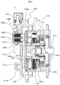
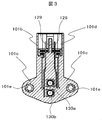
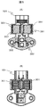
- FIG. 1 is an exploded perspective view illustrating an overall configuration of a valve timing control device for an internal combustion engine according to an embodiment of the present invention and a part (A part) thereof in an enlarged manner. It is sectional drawing of the valve timing control apparatus shown in the said FIG. It is a figure which shows an example of the power supply connector unit in the valve timing control apparatus shown in the said FIG. It is a figure which shows an example of the valve timing control apparatus in the valve timing control apparatus shown in the said FIG.
- FIG. 5 is a cross-sectional view showing cross sections A-A ′ and B-B ′ of the valve timing control device shown in FIG. 4. It is a perspective view which shows the external appearance of said valve timing control apparatus. It is a front general
- FIG. 8 is a sectional view showing an S-S ′ section of the valve timing control device shown in FIG. 7.
- FIG. 1 An outline of a valve timing control apparatus for an internal combustion engine according to an embodiment of the present invention will be described with reference to the attached FIG. 1 (entire development perspective view: FIG. 1 (A), part thereof (part A in the drawing). : FIG. 1 (B)) and FIG. 2 (partial sectional view) show a valve timing control device.
- the valve timing control device is rotatably supported via a timing sprocket 111 that is a drive rotating body that is rotationally driven by a crankshaft of an internal combustion engine, and a bearing on a cylinder head (not shown),
- the camshaft 112 (FIG.
- timing A phase change mechanism 113 (FIG. 2) is provided between the sprocket 111 and the camshaft 112 and changes the relative rotational phase of both the timing sprocket 111 and the camshaft 112 according to the engine operating state. .
- the timing sprocket 111 is integrally provided with an annular member 114 (FIG. 1A) as a driven rotor, and extends in the direction of the electric motor 103 (FIG. 2) of the phase change mechanism 113.
- a plurality of inner teeth are continuously formed at equal intervals in the circumferential direction on the inner periphery.
- a housing 115 (FIG. 1A) of the electric motor 103 and a female screw forming portion 116 (FIG. 1A) are arranged. That is, the sprocket 111 and the annular member 114 are configured as a casing of the speed reduction mechanism 117 (FIG. 2).
- the cover 104 is integrally formed in a cup shape by, for example, an aluminum alloy material, and a bulging portion 104a (FIG. 2) formed at the front end portion thereof is provided so as to cover the front end portion of the housing 115.
- a cylindrical wall 104b (FIG. 2) is integrally formed along the axial direction on the outer peripheral side of the bulging portion 104a.
- the cylindrical wall 104b has a holding hole 104c (FIG. 2) formed therein, and the inner peripheral surface of the holding hole 104c is the power connector unit 101 (FIG. 1A) of the valve timing control device. It is configured as a guide surface.
- the power connector unit 101 of the valve timing control device is also a holding body for the second brushes 303a and 303b (FIGS. 1B and 2) that constitute a power feeding structure for the electric motor 103.
- the cover 104 has four bolt insertion holes 104e formed through a flange portion 104d formed on the outer periphery (FIG. 1A), and the bolts (not shown) inserted through the bolt insertion holes 104e It is fixed to a chain cover (not shown).
- the phase change mechanism 113 reduces the rotational speed of the electric motor 103 which is an actuator disposed on the substantially coaxial front end side of the cam shaft 112 and transmits the rotation speed of the electric motor 103 to the cam shaft 112.
- a speed reduction mechanism 117 reduces the rotational speed of the electric motor 103 which is an actuator disposed on the substantially coaxial front end side of the cam shaft 112 and transmits the rotation speed of the electric motor 103 to the cam shaft 112.
- the electric motor 103 is a DC motor with a two-stage brush as shown in the attached FIG. 3 together with FIGS. 1 (A), (B) and FIG.
- the housing 115 (FIG. 1A), which is a yoke that rotates integrally, and a motor shaft 118 (output shaft), which is an intermediate rotating body that is rotatably provided inside the housing 115 (FIG. 1A, (B)), a semi-arc-shaped permanent magnet 119 which is a stator fixed to the inner peripheral surface of the housing 115 (however, the other permanent magnet to be paired is not shown) (FIG. 2)
- the inner and outer double annular slip rings 121a and 121b (FIG. 2) are fixed to a sealing plate 120 (FIG. 2) for sealing the front end opening of the housing 115, and are embedded and fixed with the outer end surface exposed. Has .
- the motor shaft 113 is formed in a stepped cylindrical shape and functions as an armature, and has a large diameter on the camshaft 112 side via a stepped portion 113c formed at a substantially central position in the axial direction. It is comprised from the part 113a and the small diameter part 113b by the side of the power supply connector unit 101.
- FIG. An iron core rotor 122 is fixed to the outer periphery of the large diameter portion 113a, and an eccentric shaft portion 123 is press-fitted and fixed in the large diameter portion 113a from the axial direction.
- the eccentric shaft portion 123 is positioned in the axial direction by the inner surface.
- a commutator 124 is press-fitted and fixed to the outer periphery of the small-diameter portion 113b from the axial direction, and is positioned in the axial direction by the outer surface of the step portion 113c.
- the iron core rotor 122 is formed of a magnetic material having a plurality of magnetic poles, and an electromagnetic coil 125 is wound around a slot formed on the outer periphery thereof.
- the electromagnetic coil 125 is disposed close to the axial direction such that the coil portion 125a on the camshaft 112 side is accommodated in the recess 115e on the front end surface of the bottom 115b of the housing 115.
- the electromagnetic coil 125 is electrically connected to each segment divided into the same number of poles of the iron core rotor 122 as the commutator 124.
- the permanent magnet 119 is formed in a cylindrical shape and has a plurality of magnetic poles in the circumferential direction, and its axial position is offset forward from the fixed position of the iron core rotor 122. Has been placed.
- the front end portion of the permanent magnet 119 is connected to the commutator (commutator) 124 and the slip rings 121a and 121b via the pigtail 129 and the pigtail harness 127 in the radial direction.
- the motor brush (first brush) 304a (304b not shown) and the like connected to each other are arranged so as to overlap.
- the slip rings 121a and 121b mainly include a disk-shaped resin plate 126 integrally provided on the inner peripheral side of the sealing plate 120 and a pair of brush holders 128a provided on the inner side of the resin plate 126. , 128b (FIG. 1B) and the brush holders 128a, 128b are slidably accommodated in the radial direction, and the respective front end surfaces thereof are commutators (commutators) by the spring force of the springs.
- First brushes 304a and 304b (not shown) that are so-called switching brushes that elastically contact the outer peripheral surface of 124 from the radial direction and front end surfaces of the brush holders 128a and 128b (FIG.
- Inner and outer double annular slip rings 121a and 121b which are embedded and fixed with their end faces exposed, and the first brushes 304a and 304. (Not shown) and the slip rings 121a, and a pigtail harness 127 Metropolitan for electrically connecting 121b.
- the slip rings 121a and 121b constitute a part of the power feeding mechanism, the first brushes 304a and 304b (not shown), the commutator 124, and the pigtail harness 127. These constitute so-called energization switching means.
- the power connector unit 101 is a power feeding mechanism integrally molded with a synthetic resin material in the bulging portion 104a (FIGS. 1A and 1B) of the cover 104. Is fixed.
- the power connector unit 101 is also a holding body for the second brushes 303a and 303b. As shown in the above-described figure, the power connector unit 101 is formed in a substantially “L” shape in a side view and is inserted into the holding hole 104c.
- the substantially cylindrical brush holding portion 101a (FIG. 2), and as shown in FIG. 3, the connector portion 101b formed mainly at the upper end of the brush holding portion 101a, and the brush holding portion 101a And a pair of bracket portions 101c fixed to the bulging portion 104a, and a pair of terminal pieces 129 that are mostly embedded in the power connector unit 101. .
- the pair of terminal pieces 129 are formed in a parallel and crank shape along the vertical direction, and each terminal on one side (lower end side) is exposed on the bottom side of the brush holding portion 101a. It is arranged. On the other hand, each terminal on the other side (upper end side) protrudes into the female fitting groove 101d of the connector portion 101b.
- the other terminal is electrically connected to a control unit and a battery power source, which are external devices, via a male terminal (not shown).
- the brush holding portion 101a extends in a substantially horizontal direction (axial direction) and slides like a sleeve in a cylindrical through-hole formed at an internal vertical position.
- the parts 130a and 130b (FIG. 3) are fixed, and the second brushes in which the front end surfaces are in contact with the slip rings 121a and 121b from the axial direction inside the sliding parts 130a and 130b, respectively.
- 303a and 303b are slidably held in the axial direction.
- Each of these second brushes 303a and 303b is an urging member that is formed in a substantially rectangular shape and is elastically mounted between the one side terminal facing the bottom side of each through hole.
- the springs 309a and 309b are biased toward the slip rings 121a and 121b, respectively.
- a pair of flexible pigtail harnesses are welded and fixed between the rear ends of the second brushes 303a and 303b and the one-side terminals to electrically connect the two.
- the length of the pigtail harness is such that the second brushes 303a and 303b do not fall off the sliding portions 130a and 130b (FIG. 3) even when the second brushes 303a and 303b are advanced to the maximum by the springs 309a and 309b.
- the length is set to regulate the maximum sliding position.
- the connector 101b has a male terminal (not shown) inserted into the upper end thereof, and the other terminal facing the fitting groove 101d is connected to a control unit (not shown) and a battery power source via the male terminal. Electrically connected.
- the bracket portion 101c is formed in a substantially triangular shape, and bolt insertion holes 101e are formed through both sides thereof (FIG. 3). Each bolt insertion hole 101e is inserted with each bolt 131 that is screwed into a pair of female screw holes (not shown) formed in the bulging portion 104a of the cover 104, and via each bracket portion 101c.
- the power connector unit 101 is fixed to the bulging portion 104 a of the cover 104.
- the inventor of the present application particularly drives and drives the power source connector unit 101 by electrically connecting a battery power source via a male terminal and an electronic control unit (not shown) in the electric valve timing control device having the above-described configuration.
- an electronic control unit not shown
- the causes of electromagnetic noise emissions during the driving were investigated. The results will be described below.
- electromagnetic noise emissions occur from the following locations: (1) Between the first brushes 304a and 304b (not shown) and a commutator 124, and (2) Outer end surfaces of the second brushes 303a and 303b constituting the power feeding structure for the electric motor 103 and the disc-shaped resin plate 126 integrally provided on the inner peripheral side of the sealing plate 120. Between the inner and outer double annular slip rings 121a, 121b embedded and fixed in an exposed state, and It has been found that these are the majority of the electromagnetic noise emissions generated by the electric valve timing control device.
- electromagnetic noise emission suppression means for suppressing the electromagnetic noise emission generated from the two locations described above is provided on the power supply side of the second brush 303a, 303b.
- electromagnetic noise emission suppression means as shown in FIGS. 4 and 5, the inductive element (coil) 301 and the capacitive element (capacitor) 302 are respectively connected.
- the inductive element (coil) 301 and the capacitive element (capacitor) 302 are respectively connected.
- a simple configuration in which only one unit is used, that is, a pair is adopted.
- the present invention is not limited to this.
- the number of each element may be two or more, or another element may be used.
- the inductive element (coil) 301 includes a magnetic core 307 at the center.
- the present invention is not limited to the above-described electromagnetic noise emission suppression effect.
- the characteristics of the valve timing control device for an internal combustion engine according to the present invention are considered, that is, the space in the limited engine room of the automobile is effectively used.
- the electromagnetic noise emission sources of (1) and (2) described above are brought close to each other so that the electromagnetic noise generated from both electromagnetic noise emission sources can be reduced to the minimum one-stage electromagnetic noise. It has been found that it is preferable to suppress it by means of emission suppression.
- the coil energization switching mechanism is made using a brush, and the current from the outside is
- the brush to be supplied (second brush) and the brush (first brush) of the energization switching mechanism of the coil were arranged so as to be substantially the same distance from the rotation axis of the device (camshaft).
- electrodes, inductive elements are directed outward.
- (Coil) 301 and connector terminals are arranged in this order, and both electrode terminals embedded in the power supply connector unit 101 are connected to a brush between two wires connecting the connector terminals, and a capacitive element (capacitor) 302 Can be integrated into the power connector unit 101 by arranging them in the circumferential direction on both sides of the electrode.
- the inductive element (coil) 301 is arranged in series with the electrode, and the capacitive element (capacitor) 302 is arranged in parallel with the electrode in the power connector unit. It was arranged between 306 mounting screw holes.
- a terminal on the opposite side to the terminal connected to the electrode of the capacitive raw element 302 is connected between the mounting screw holes of the power connector unit 306, and a flange portion formed on the outer periphery via the cover 104.
- Four bolt insertion holes 104e are formed through 104d, and are fixed to the chain cover (not shown) by bolts (not shown) inserted through the bolt insertion holes 104e, so that they are electrically connected to the engine ground (body ground). Will be connected.
- FIG. 6 attached herewith shows an overview of the electric valve timing control device provided with the electromagnetic noise emission suppression means described above. That is, compared with the conventional electric valve timing control device, the central portion of the power connector unit 101 and the portion where the inductive element (coil) 301 is installed are substantially equivalent to one inductive element (coil) 301. It can be seen that the electromagnetic noise emission suppressing means can be provided while maintaining the compactness of the entire apparatus, although the volume of the apparatus is increased.
- the power connector unit 101 is electrically connected to a battery power source via a male terminal and an electronic control unit (not shown), and an international organization Based on the standards issued by IEC and CISPR, the electromagnetic noise emission during driving was measured in the same manner as described above.
- the electromagnetic noise emission was 13 dB ( ⁇ V / m) at maximum compared to the electromagnetic noise emission suppression means. It was found that the suppression could be realized.
- the electromagnetic noise emission is effectively suppressed by bringing a plurality of electromagnetic noise emission generation sources close to each other and installing the electromagnetic noise emission suppressing means at a high density, Furthermore, the reliability of the valve timing control device for the internal combustion engine can be improved at a low cost by fixing the elements constituting the electromagnetic noise emission suppressing means. Furthermore, by integrating the electromagnetic noise emission suppression means into an electronic control unit, the valve timing control device for an internal combustion engine can be designed in a modular manner while maintaining the overall compactness of the device. It becomes possible to facilitate the work and further to facilitate the product management.
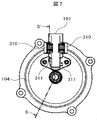
- FIG. 7 is a schematic front view of the cover 104 including the power connector unit 101.
- FIG. 8 is a cross-sectional view taken along the line S-S ′ of FIG.
- the valve timing control device is a device that is directly attached (directly mounted) to the engine. Therefore, the electromagnetic noise emission suppression means includes a response to vibration from the engine, and further, the valve timing control device. Since it is arranged in the engine room, which is a limited vehicle space, it is important to consider the heat dissipation of the electronic components constituting the electromagnetic noise emission suppressing means.
- the power connector unit 101 is configured such that the entire inductive element (coil) 301 and the capacitive raw element (capacitor) 302 are covered with resin.
- the inductive element (coil) 301 is arranged in series with the electrode, a current having a large current value flows similarly to the current flowing through the motor, and thus the amount of heat generated by Joule heat is also large.
- the element is covered with resin, heat is likely to be generated in the element, and there is a concern about deterioration of element characteristics due to heat.
- a window is provided in the resin of the element portion. More specifically, as shown in FIGS. 7 and 8, a window 310 is attached to the inductive element portion, and a similar window 311 is attached to the capacitive element portion.
- the shape of the window described above an example in which the shape is rectangular is shown, as in the case of the outer shape of the element.
- the shape is not limited to a rectangle.
- the window can be divided into a mesh shape or a slit shape.
- electromagnetic noise emission is effectively suppressed by bringing a plurality of electromagnetic noise emission generation sources close to each other and installing the electromagnetic noise emission suppression means at a high density.
- electromagnetic noise emission suppression means In addition to fixing the elements constituting the noise emission suppressing means, it is possible to improve the heat dissipation of the elements, thereby improving the reliability of the valve timing control device for the internal combustion engine at low cost.
- electromagnetic noise emission suppression means into an electronic control unit, modular design is possible while maintaining the overall compactness of the device, facilitating manufacturing and assembly operations, and product Management can be facilitated.
- the permanent magnet 119 was used as the said stator, other than this It is also possible to use other stators.
- the DC motor may be a brushless using a semiconductor, but the cost is higher than that with the brush shown in the configuration of the embodiment, and in the case of the brushless, the switching control by the semiconductor is performed. The power usage efficiency is lower than that of the system.
- valve timing control apparatus for an internal combustion engine according to the present invention described above, leakage of noise to the outside of the valve timing control apparatus for the internal combustion engine can be suppressed, and the influence on other apparatuses can be suppressed.
- a total of two electromagnetic noise emission suppression means must be arranged for each of the motor coil energization switching mechanism and the brush constituting the external power supply means.
- the switching mechanism and the electromagnetic noise emission suppression means are arranged in the vicinity of each other, in particular, the brush and coil energization switching mechanism for supplying an electric current from the outside is arranged in the vicinity of each other, and further, arranged at substantially the same distance from the rotating shaft.
- the problem due to vibration can be solved by molding and fixing the electromagnetic noise emission suppression means with resin. Furthermore, it is possible to enhance the heat dissipation effect by partially molding the electronic components constituting the electromagnetic noise emission suppressing means with resin. That is, the reliability of the valve timing control device for the internal combustion engine can be improved.
Landscapes
- Engineering & Computer Science (AREA)
- Mechanical Engineering (AREA)
- General Engineering & Computer Science (AREA)
- Power Engineering (AREA)
- Valve Device For Special Equipments (AREA)
Abstract
Description
(1)前記第1のブラシ304a、304b(図示せず)と整流子(コミューテータ)124との間、並びに、
(2)電動モータ103に対する給電構造を構成する第2のブラシ303a、303bと、前記封止プレート120の内周側に一体的に設けられた円板状の樹脂プレート126各に対して外端面を露出した状態で埋設固定された内外二重の円環状のスリップリング121a、121bとの間、そして、
それらが、電動式バルブタイミング制御装置の発生する電磁ノイズエミッションの大部分であることが判った。
Claims (8)
- 内燃機関のクランクシャフトからの回転力が伝達される駆動回転体と、
前記駆動回転体から回転力が伝達されると共に、カムシャフトに固定された従動回転体と、
少なくともボールベアリングを備えた軸受機構によって前記従動回転体に軸受されると共に、前記駆動回転体に対して相対回転可能に設けられた中間回転体と、
前記中間回転体を前記駆動回転体に対して相対回転させることによって、前記中間回転体の回転を減速して前記従動回転体に伝達する減速機構と、
前記中間回転体を前記駆動回転体に対して相対回転するように設けられ、外部からの電流の供給によって回転駆動する電動モータと、
前記駆動回転体に一体に設けられ、内部に前記電動モータを収容したハウジングとを備えた内燃機関のバルブタイミング制御装置において、
前記電動モータは、前記カムシャフトに対して相対的に回転運動すると共に、前記ハウジングに対しても、相対的に回転運動し、当該バルブタイミング制御装置は、更に、
前記ハウジングの内部に設けられ、前記電動モータのコイルへの通電を切り換えるためのブラシを含む通電切換機構と、
前記ハウジングと外部機器との間に設けられ、当該外部機器からの電流を前記通電切換機構に給電するためのブラシを含む給電機構と
を備えており、かつ、
誘導性素子と容量生素子とからなる電磁ノイズエミッション抑制手段を、前記給電機構のブラシの電源側に設けたことを特徴とする内燃機関のバルブタイミング制御装置。 - 請求項1に記載のバルブタイミング制御装置おいて、前記通電切換機構と前記電磁ノイズエミッション抑制手段とは、互いに近傍に配置されていることを特徴とする内燃機関のバルブタイミング制御装置。
- 請求項1に記載のバルブタイミング制御装置おいて、前記通電切換機構のブラシと前記給電機構のブラシを、前記カムシャフトの回転軸に対して略同じ距離になるように配置したことを特徴とする内燃機関のバルブタイミング制御装置。
- 請求項2または3に記載のバルブタイミング制御装置おいて、前記電磁ノイズエミッション抑制手段を構成する誘導性素子は、電源ラインに直列に接続され、かつ、前記容量性素子は、前記電源ラインと筐体グランドとの間に接続されていることを特徴とする内燃機関のバルブタイミング制御装置。
- 請求項4に記載のバルブタイミング制御装置おいて、前記誘導性素子と前記容量性素子の全体もしくは一部が金属筐体の外部に存在することを特徴とする内燃機関のバルブタイミング制御装置。
- 請求項4に記載のバルブタイミング制御装置おいて、前記誘導性素子と前記容量性素子とが樹脂でモールドされていることを特徴とする内燃機関のバルブタイミング制御装置。
- 請求項4に記載のバルブタイミング制御装置おいて、前記誘導性素子の一部が樹脂でモールドされていることを特徴とする内燃機関のバルブタイミング制御装置。
- 請求項4に記載のバルブタイミング制御装置おいて、前記容量性素子の一部が樹脂でモールドされていることを特徴とする内燃機関のバルブタイミング制御装置。
Priority Applications (3)
| Application Number | Priority Date | Filing Date | Title |
|---|---|---|---|
| CN201480014016.6A CN105189947B (zh) | 2013-09-26 | 2014-07-01 | 内燃机的配气正时控制装置 |
| US14/774,463 US9784146B2 (en) | 2013-09-26 | 2014-07-01 | Valve timing control device for internal combustion engine |
| JP2015538964A JP6121553B2 (ja) | 2013-09-26 | 2014-07-01 | 内燃機関のバルブタイミング制御装置 |
Applications Claiming Priority (2)
| Application Number | Priority Date | Filing Date | Title |
|---|---|---|---|
| JP2013200001 | 2013-09-26 | ||
| JP2013-200001 | 2013-09-26 |
Publications (1)
| Publication Number | Publication Date |
|---|---|
| WO2015045542A1 true WO2015045542A1 (ja) | 2015-04-02 |
Family
ID=52742700
Family Applications (1)
| Application Number | Title | Priority Date | Filing Date |
|---|---|---|---|
| PCT/JP2014/067494 Ceased WO2015045542A1 (ja) | 2013-09-26 | 2014-07-01 | 内燃機関のバルブタイミング制御装置 |
Country Status (4)
| Country | Link |
|---|---|
| US (1) | US9784146B2 (ja) |
| JP (1) | JP6121553B2 (ja) |
| CN (1) | CN105189947B (ja) |
| WO (1) | WO2015045542A1 (ja) |
Cited By (5)
| Publication number | Priority date | Publication date | Assignee | Title |
|---|---|---|---|---|
| WO2016158158A1 (ja) * | 2015-03-30 | 2016-10-06 | 日立オートモティブシステムズ株式会社 | 内燃機関のバルブタイミング制御装置 |
| JP2016205136A (ja) * | 2015-04-15 | 2016-12-08 | 日立オートモティブシステムズ株式会社 | 内燃機関のバルブタイミング制御装置 |
| WO2017208626A1 (ja) * | 2016-05-31 | 2017-12-07 | 日立オートモティブシステムズ株式会社 | バルブタイミング制御装置 |
| WO2018016133A1 (ja) * | 2016-07-19 | 2018-01-25 | 日立オートモティブシステムズ株式会社 | 内燃機関のバルブタイミング制御装置 |
| JP2022515921A (ja) * | 2019-01-17 | 2022-02-22 | ジョンソン エレクトリック インターナショナル アクチェンゲゼルシャフト | Dcモータのためのemiフィルタ |
Families Citing this family (2)
| Publication number | Priority date | Publication date | Assignee | Title |
|---|---|---|---|---|
| JP6354560B2 (ja) * | 2014-12-12 | 2018-07-11 | 株式会社デンソー | 電磁アクチュエータ |
| US10739726B2 (en) | 2018-10-03 | 2020-08-11 | International Business Machines Corporation | Audio management for holographic objects |
Citations (4)
| Publication number | Priority date | Publication date | Assignee | Title |
|---|---|---|---|---|
| JP2002165413A (ja) * | 2000-09-13 | 2002-06-07 | Asmo Co Ltd | モータ |
| JP2004056894A (ja) * | 2002-07-18 | 2004-02-19 | Mitsuba Corp | 電動モータ |
| JP2011226372A (ja) * | 2010-04-20 | 2011-11-10 | Hitachi Automotive Systems Ltd | 内燃機関のバルブタイミング制御装置 |
| JP2013100832A (ja) * | 2013-03-07 | 2013-05-23 | Hitachi Automotive Systems Ltd | 内燃機関のバルブタイミング制御装置 |
Family Cites Families (4)
| Publication number | Priority date | Publication date | Assignee | Title |
|---|---|---|---|---|
| US4818960A (en) * | 1987-04-06 | 1989-04-04 | Tdk Corporation | Composite part and method of manufacturing same |
| JP3545172B2 (ja) | 1997-07-29 | 2004-07-21 | 株式会社日立ユニシアオートモティブ | 燃料ポンプおよび該ポンプ用吐出カバーへの電気部品実装方法 |
| JP2008215121A (ja) | 2007-03-01 | 2008-09-18 | Denso Corp | 燃料ポンプ |
| JP4987031B2 (ja) | 2009-04-27 | 2012-07-25 | 日立オートモティブシステムズ株式会社 | 内燃機関のバルブタイミング制御装置 |
-
2014
- 2014-07-01 JP JP2015538964A patent/JP6121553B2/ja not_active Expired - Fee Related
- 2014-07-01 CN CN201480014016.6A patent/CN105189947B/zh not_active Expired - Fee Related
- 2014-07-01 US US14/774,463 patent/US9784146B2/en not_active Expired - Fee Related
- 2014-07-01 WO PCT/JP2014/067494 patent/WO2015045542A1/ja not_active Ceased
Patent Citations (4)
| Publication number | Priority date | Publication date | Assignee | Title |
|---|---|---|---|---|
| JP2002165413A (ja) * | 2000-09-13 | 2002-06-07 | Asmo Co Ltd | モータ |
| JP2004056894A (ja) * | 2002-07-18 | 2004-02-19 | Mitsuba Corp | 電動モータ |
| JP2011226372A (ja) * | 2010-04-20 | 2011-11-10 | Hitachi Automotive Systems Ltd | 内燃機関のバルブタイミング制御装置 |
| JP2013100832A (ja) * | 2013-03-07 | 2013-05-23 | Hitachi Automotive Systems Ltd | 内燃機関のバルブタイミング制御装置 |
Cited By (8)
| Publication number | Priority date | Publication date | Assignee | Title |
|---|---|---|---|---|
| WO2016158158A1 (ja) * | 2015-03-30 | 2016-10-06 | 日立オートモティブシステムズ株式会社 | 内燃機関のバルブタイミング制御装置 |
| JPWO2016158158A1 (ja) * | 2015-03-30 | 2017-12-21 | 日立オートモティブシステムズ株式会社 | 内燃機関のバルブタイミング制御装置 |
| JP2016205136A (ja) * | 2015-04-15 | 2016-12-08 | 日立オートモティブシステムズ株式会社 | 内燃機関のバルブタイミング制御装置 |
| WO2017208626A1 (ja) * | 2016-05-31 | 2017-12-07 | 日立オートモティブシステムズ株式会社 | バルブタイミング制御装置 |
| WO2018016133A1 (ja) * | 2016-07-19 | 2018-01-25 | 日立オートモティブシステムズ株式会社 | 内燃機関のバルブタイミング制御装置 |
| JPWO2018016133A1 (ja) * | 2016-07-19 | 2019-05-16 | 日立オートモティブシステムズ株式会社 | 内燃機関のバルブタイミング制御装置 |
| JP2022515921A (ja) * | 2019-01-17 | 2022-02-22 | ジョンソン エレクトリック インターナショナル アクチェンゲゼルシャフト | Dcモータのためのemiフィルタ |
| JP7130880B2 (ja) | 2019-01-17 | 2022-09-05 | ジョンソン エレクトリック インターナショナル アクチェンゲゼルシャフト | Dcモータのためのemiフィルタ |
Also Published As
| Publication number | Publication date |
|---|---|
| US20160032795A1 (en) | 2016-02-04 |
| JP6121553B2 (ja) | 2017-04-26 |
| JPWO2015045542A1 (ja) | 2017-03-09 |
| CN105189947A (zh) | 2015-12-23 |
| CN105189947B (zh) | 2017-10-24 |
| US9784146B2 (en) | 2017-10-10 |
Similar Documents
| Publication | Publication Date | Title |
|---|---|---|
| JP6121553B2 (ja) | 内燃機関のバルブタイミング制御装置 | |
| JP4410159B2 (ja) | 交流回転電機 | |
| CN112771770A (zh) | 电动致动器 | |
| JP2014150724A (ja) | 電動モータ、および減速機付モータ | |
| JP6139785B2 (ja) | 内燃機関の弁ユニットを駆動するアクチュエータ | |
| JP6848474B2 (ja) | シールド構造を備えたモータ装置 | |
| US20160301291A1 (en) | Coreless motor for throttle controlling device, method for manufacturing coreless motor for throttle controlling device, and throttle controlling device | |
| US20180304826A1 (en) | Noise filter of vehicle-mounted device and vehicle-mounted device | |
| JP2021052493A (ja) | モータおよびモータの組立方法 | |
| JP2008206310A (ja) | 電動モータ | |
| CN103312073B (zh) | 电机以及制造电机的方法 | |
| CN103312076A (zh) | 电机以及用于电机的方法 | |
| JP6536249B2 (ja) | 回転電機 | |
| CN104701086B (zh) | 往复电磁铁、电机以及用于制造往复电磁铁的方法 | |
| CN105026748B (zh) | 发动机起动装置 | |
| US11183806B2 (en) | DC motor brush holder assembly | |
| CN224083346U (zh) | 带制动器的马达 | |
| JP5976529B2 (ja) | 内燃機関のバルブタイミング制御装置及び該バルブタイミング制御装置に用いられるカバー部材 | |
| JP2019044603A (ja) | 内燃機関のバルブタイミング制御装置と該バルブタイミング制御装置に用いられる固定部材 | |
| CN104377893A (zh) | 电机和用于制造和/或驱动电机的方法 | |
| JP2016205136A (ja) | 内燃機関のバルブタイミング制御装置 | |
| KR20190142598A (ko) | 전자파 적합성을 향상할 수 있는 직류 전동기 | |
| JP2023104510A (ja) | 電制スロットル装置 | |
| KR20180095323A (ko) | 쿨링팬 모터 조립체 | |
| WO2024084845A1 (ja) | 電動機 |
Legal Events
| Date | Code | Title | Description |
|---|---|---|---|
| WWE | Wipo information: entry into national phase |
Ref document number: 201480014016.6 Country of ref document: CN |
|
| 121 | Ep: the epo has been informed by wipo that ep was designated in this application |
Ref document number: 14848128 Country of ref document: EP Kind code of ref document: A1 |
|
| WWE | Wipo information: entry into national phase |
Ref document number: 14774463 Country of ref document: US |
|
| ENP | Entry into the national phase |
Ref document number: 2015538964 Country of ref document: JP Kind code of ref document: A |
|
| NENP | Non-entry into the national phase |
Ref country code: DE |
|
| 122 | Ep: pct application non-entry in european phase |
Ref document number: 14848128 Country of ref document: EP Kind code of ref document: A1 |