WO2015041101A1 - 共振周波数算出装置、撮像装置、共振周波数算出プログラムおよび共振周波数算出方法 - Google Patents
共振周波数算出装置、撮像装置、共振周波数算出プログラムおよび共振周波数算出方法 Download PDFInfo
- Publication number
- WO2015041101A1 WO2015041101A1 PCT/JP2014/073809 JP2014073809W WO2015041101A1 WO 2015041101 A1 WO2015041101 A1 WO 2015041101A1 JP 2014073809 W JP2014073809 W JP 2014073809W WO 2015041101 A1 WO2015041101 A1 WO 2015041101A1
- Authority
- WO
- WIPO (PCT)
- Prior art keywords
- resonance frequency
- actuator
- lens
- drive
- frequency calculation
- Prior art date
- Legal status (The legal status is an assumption and is not a legal conclusion. Google has not performed a legal analysis and makes no representation as to the accuracy of the status listed.)
- Ceased
Links
Images






Classifications
-
- G—PHYSICS
- G02—OPTICS
- G02B—OPTICAL ELEMENTS, SYSTEMS OR APPARATUS
- G02B7/00—Mountings, adjusting means, or light-tight connections, for optical elements
- G02B7/28—Systems for automatic generation of focusing signals
- G02B7/36—Systems for automatic generation of focusing signals using image sharpness techniques, e.g. image processing techniques for generating autofocus signals
-
- G—PHYSICS
- G02—OPTICS
- G02B—OPTICAL ELEMENTS, SYSTEMS OR APPARATUS
- G02B7/00—Mountings, adjusting means, or light-tight connections, for optical elements
- G02B7/02—Mountings, adjusting means, or light-tight connections, for optical elements for lenses
- G02B7/04—Mountings, adjusting means, or light-tight connections, for optical elements for lenses with mechanism for focusing or varying magnification
- G02B7/08—Mountings, adjusting means, or light-tight connections, for optical elements for lenses with mechanism for focusing or varying magnification adapted to co-operate with a remote control mechanism
Definitions
- the present invention relates to a resonance frequency calculation device, an imaging device, a resonance frequency calculation program, and a resonance frequency calculation method.
- VCM voice coil motor
- AF autofocus
- the resonance vibration of the actuator by appropriately setting the signal for driving the actuator. If the resonance frequency of the actuator of each camera can be calculated at the adjustment stage of the production line or the like, the resonance vibration of each actuator can be suppressed. However, for that purpose, it is necessary to accurately grasp the individual variation of the resonance frequency of the actuator.
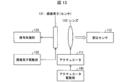
- the actuator 111 moves the lens 110 to a target position according to an instruction from the actuator driving unit 140.
- the image sensor 131 captures an image transmitted through the lens 110 in response to an instruction from the image sensor driver 132, and the signal processor 133 processes the captured image.
- a displacement sensor 112 is provided in the camera module of Patent Document 1.
- the resonance vibration of the actuator 111 generated when the lens 110 is moved to a target position is observed by the displacement sensor 112, and the resonance frequency of the actuator 111 is calculated from the observed resonance vibration.
- the resonance frequency of the actuator is calculated based on a signal from the displacement sensor 112.
- it in order to measure the resonance frequency with the displacement sensor attached, it has high accuracy.
- it is expensive to introduce a displacement sensor in a production line.
- the present invention has been made to solve the above-described problems, and an object thereof is to calculate the resonance frequency of the actuator without requiring high accuracy and high cost.
- a resonance frequency calculation apparatus calculates a resonance frequency of vibration generated in an actuator when a lens moved by the actuator is stopped at a predetermined position.
- a frequency calculation device wherein a driving signal for driving the actuator is output to the actuator a plurality of times at different driving frequencies, and a first position different from the in-focus position by the driving signal of the different driving frequencies.
- a captured image acquisition unit that acquires a plurality of captured images of the subject image obtained by moving the lens a plurality of times from the position to the second position that is the in-focus position, and each contrast value of the plurality of captured images
- a contrast value calculation unit for calculating the image and a captured image with the highest contrast value among the plurality of captured images
- a and a resonant frequency calculation unit for calculating a resonant frequency that is used to calculate the drive frequency of the drive signal of driving the actuator.
- a resonance frequency calculation method includes a resonance frequency calculation for calculating a resonance frequency of vibration generated in the actuator when a lens moved by the actuator is stopped at a predetermined position.
- a method for calculating a frequency wherein a driving signal for driving the actuator is output to the actuator a plurality of times at different driving frequencies, and the lens is made different from the in-focus position by the driving signal having the different driving frequency. Moving a plurality of times from the first position to the second position, which is the in-focus position, obtaining a plurality of captured images of the subject image, calculating a contrast value of each of the plurality of captured images, In order to obtain a captured image with the highest contrast value among the captured images of And a step of calculating a resonant frequency that is used to calculate the drive frequency of the drive signal.
- FIG. 3 is a diagram illustrating a processing flow of the imaging apparatus according to the first embodiment. It is a figure showing the image for focus adjustment. It is a figure showing the structure of the imaging device which concerns on Embodiment 2 of this invention. It is a figure showing the resonance of the lens of Embodiment 2, and an exposure period.
- FIG. 6 is a diagram illustrating a processing flow of the imaging apparatus according to the second embodiment.
- FIG. 10 is a diagram illustrating a state of lens vibration in the imaging device according to the third embodiment.
- FIG. 10 is a diagram illustrating a processing flow of the imaging apparatus according to the third embodiment. It is a figure showing the mode of the resonant vibration of a lens. It is a figure showing the structure of the conventional imaging device.
- FIG. 1 is a diagram illustrating a configuration of an imaging apparatus 1 according to the first embodiment.
- the imaging device 1 includes a resonance frequency calculation device 5, a lens 10, an actuator 11, a diaphragm mechanism 12, a storage unit 17, and an imaging unit 30.
- the resonance frequency calculation device 5 includes an aperture mechanism control unit 13, a contrast value calculation unit (contrast value storage unit) 14, a resonance frequency calculation unit 15, and an actuator drive unit (exposure start instruction unit) 40.
- the imaging unit 30 includes an imaging element 31, an imaging element drive control unit 32, and a captured image acquisition unit 33.
- the diaphragm mechanism 12 and the diaphragm mechanism control unit 13 may be omitted, and a mechanism for adjusting the exposure amount from the lens 10 to the image sensor 31 may be provided.
- the actuator 11 holds the lens 10 and moves the lens 10 based on the drive signal from the actuator drive unit 40 to move the relative position between the lens 10 and the image sensor 31.
- the actuator 11 includes a drive unit as a power source that moves the lens 10 and a biasing member that moves the lens 10 by biasing the power from the drive unit and transmitting the power to the lens 10.
- the actuator 11 has resonance force when the lens 10 is moved to a target position at high speed due to the provision of the biasing member.
- An example of the drive unit of the actuator 11 is a VCM, and an example of the biasing member is a spring.
- the aperture mechanism 12 has an aperture that opens and closes according to an instruction from the aperture mechanism control unit 13 in order to adjust the amount of light incident from the lens 10 to the image sensor 31.
- the aperture mechanism 12 is disposed, for example, between the lens 10 and the image sensor 31.
- the image sensor 31 receives the transmitted light from the lens 10 from the light receiving surface, photoelectrically converts it, and outputs it as an electrical signal.
- the imaging element 31 is a light receiving element such as a CCD or a CMOS.
- the image sensor drive control unit 32 controls driving of the image sensor 31.
- the captured image acquisition unit 33 acquires a captured image from the electrical signal output from the image sensor 31.
- the resonance frequency calculation device 5 calculates the resonance frequency of vibration generated in the actuator 11 when the lens 10 moved by the actuator 11 is stopped at a predetermined position.
- the contrast value calculation unit 14 calculates the contrast value of the captured image acquired by the captured image acquisition unit 33. Then, the contrast value calculation unit 14 stores the resonance frequency used for calculating the drive frequency of the drive signal for driving the actuator 11 to obtain the captured image and the calculated contrast value in association with each other. 17 stored.
- the resonance frequency calculation unit 15 compares the magnitudes of a plurality of contrast values stored in the storage unit 17, specifies the highest contrast value, and stores it in association with the specified highest contrast value. By specifying the resonance frequency that is present, the resonance frequency specific to the actuator 11 is calculated.
- the resonance frequency stored in the storage unit 17 in association with the highest contrast value identified by the resonance frequency calculation unit 15 is a drive that drives the actuator 11 to obtain a captured image that has obtained the contrast value. This is the resonance frequency used for the drive frequency calculation unit 41 to calculate the drive frequency of the signal.
- the actuator driving unit 40 includes a driving frequency calculating unit 41.
- the drive frequency calculation unit 41 may be provided outside the actuator drive unit 40, and may be further provided outside the resonance frequency calculation device 5.
- the actuator drive unit 40 controls the drive of the actuator 11.
- the drive frequency calculator 41 calculates the drive frequency by multiplying the resonance frequency by a predetermined integer.
- the actuator drive unit 40 generates a drive signal having the drive frequency calculated by the drive frequency calculation unit 41, and drives the actuator 11 by outputting the generated drive signal to the actuator 11.
- the actuator driving unit 40 controls driving of the actuator 11 by outputting a driving signal for driving the actuator 11 to the actuator 11 a plurality of times at different driving frequencies.
- the actuator driving unit 40 stores the number of repetitions i for outputting a driving signal having different driving frequencies to the actuator 11 a plurality of times.
- the drive frequency of the drive signal of the actuator 11 is generally determined by the spring constant when a spring is used for the actuator 11. If this drive frequency is determined, the resonance frequency of the actuator 11 is also determined. However, the inherent resonance frequency of the actuator 11 currently in use varies depending on the actuator 11 and the position of the lens 10.
- the actuator drive unit 40 outputs drive signals at equal intervals from the upper limit drive frequency calculated from the upper limit of the variation in the resonance frequency of the actuator 11 to the drive frequency calculated from the lower limit of the variation in the resonance frequency of the actuator 11. Then, the actuator 11 is driven by each drive signal. In addition, the actuator driving unit 40 stores the resonance frequency used for calculating the driving frequency of the driving signal that has driven the actuator 11 in the storage unit 17.
- the storage unit 17 calculates the resonance frequency used to calculate the drive frequency of the drive signal used to drive the actuator 11 to obtain the captured image acquired by the captured image acquisition unit 33 and the contrast value from the captured image.
- the contrast value calculated by the unit 14 is stored in association with it.
- FIG. 5 is a diagram illustrating an example of a focus adjustment image. As shown in FIG. 5, it is preferable to use an image in which the edge of white and black is clear and the contrast of the edge portion is high as the focus adjustment image 9. As an example, the focus adjustment image 9 in FIG. 5 uses a Siemens Star chart in which white areas and black areas are radially arranged. The focus adjustment image 9 is not limited to the Siemens Star chart, and may be any image as long as the shape of the focus area is symmetrical and the contrast is high.
- FIG. 2 is a diagram showing the resonance of the lens of the imaging device 1 and the exposure period.
- the vertical axis in FIG. 2 represents the position of the lens 10 in the imaging apparatus 1, and the horizontal axis represents time.
- the position x0 is a movement start position (initial position) of the lens 10 in the imaging apparatus 1, and is not a focus position.
- the position x1 is a focus position of the lens 10 with respect to the focus adjustment image 9. That is, the position x1 is a position where the lens 10 is in focus with respect to the focus adjustment image 9.
- An example of a method for calculating the position x1 is autofocus.
- the actuator driving unit 40 moves the lens 10 through the actuator 11 from the initial position x0 to the target focus position x1
- the actuator 11 resonates at the position x1, so that the lens 10 is also centered on the position x1. Will resonate.
- the image is more blurred as the position of the lens 10 is farther from the position x1.
- the actuator drive unit 40 In order for the actuator drive unit 40 to move the lens 10 from the position x0 to the position x1 through the actuator 11, the closer the drive frequency of the drive signal output to the actuator 11 is to the inherent resonance frequency of the actuator 11, the closer the lens
- the resonance of the actuator 11 that occurs at the position x1 when the position 10 is moved to the target position x1 can be suppressed. As a result, the resonance of the lens 10 at the position x1 can be suppressed.
- the vibration y1 represents the vibration of the lens 10 at the position x1 when the actuator 11 is driven by a drive signal having a drive frequency calculated from a vibration frequency close to the inherent resonance frequency of the actuator 11.
- the vibration y1 is small with respect to the position x1, and the time for the vibration to converge is short.
- the vibration y2 represents the vibration of the lens 10 at the position x1 when the drive frequency of the drive signal of the actuator 11 is calculated from the inherent resonance frequency of the actuator 11 and the far vibration frequency.
- the vibration y2 has a larger vibration than the vibration y1. As shown in regions A and B, the farther the position of the lens 10 is from the position x1, the more seriously the image is out of focus. The vibration y2 takes a longer time for the vibration to converge than the vibration y1.
- the lens 10 is moved from the time t0 to the position x1 that is the in-focus position, and a predetermined period has elapsed. Until the time tt, the aperture of the aperture mechanism 12 is opened and exposed to obtain a captured image of the focus adjustment image 9.
- the vibration frequency used to calculate the drive frequency of the drive signal that has driven the actuator 11 is close to the inherent resonance frequency of the actuator 11.
- the vibration frequency used to calculate the drive frequency of the drive signal that has driven the actuator 11 is significantly different from the inherent resonance frequency of the actuator 11.
- the high-frequency component of the captured image is extracted by performing a filtering process such as a high-pass filter on the luminance signal of the captured image, and the integral value of the extracted high-frequency component is generated to obtain the contrast value of the captured image. Obtainable.
- FIG. 3 is a diagram showing the relationship between the contrast value obtained from the captured image and the vibration frequency of the actuator.
- the drive frequency of the actuator drive signal is obtained from the vibration frequency of the actuator.
- the drive frequency of the drive signal of the actuator 11 is determined by the spring constant of the spring.
- the drive frequency of the drive signal of the actuator 11 is, for example, the lower limit vibration obtained from the lower limit from the upper limit vibration frequency obtained from the upper limit of the variation in resonance vibration between the individual actuators 11 and the position. Shake up to the frequency every measurement step a at approximately equal intervals.
- the resonance frequency of the actuator is about 60 Hz, and the variation is about ⁇ 15 Hz.
- the contrast values of the captured images obtained when the actuator 11 is driven at the vibration frequency obtained from each of the measurement steps a are compared.
- the vibration frequency at which the drive frequency N of the actuator 11 used to capture the captured image from which the contrast value is obtained is the current value. It can be estimated that the resonance frequency is unique to the actuator 11 being used.
- the drive frequency of the drive signal of the actuator 11 is obtained by multiplying the resonance frequency of the actuator 11 thus obtained by an integer.
- the resonance frequency of the actuator 11 is 60 Hz
- the drive frequency of the drive signal of the actuator 11 is about 120 Hz, which is twice the resonance frequency.
- the drive frequency of the drive signal of the actuator 11 may be an integer multiple of the resonance frequency.
- the magnification may be determined in advance.
- FIG. 4 is a flowchart showing the flow of processing of the imaging apparatus 1.
- the imaging device 1 acquires a position x1 at which the lens 10 is in focus with respect to the focus adjustment image 9.
- autofocus can be mentioned.
- various methods such as contrast AF and phase difference AF can be used.
- the drive frequency calculation unit 41 calculates the drive frequency by multiplying the resonance frequency f by an integer.
- the actuator drive unit 40 stores the resonance frequency f in the storage unit 17 together with information specifying the resonance frequency f, generates a drive signal at the calculated drive frequency, and uses the generated drive signal as an actuator. 11 is output.
- the actuator 11 moves the lens 10 from the initial position x0 to the in-focus position x1 by the drive signal (S13).
- the aperture mechanism control unit 13 opens the aperture of the aperture mechanism 12.
- the image sensor 31 converts the light received from the lens 10 into an electrical signal, and outputs the converted electrical signal to the captured image acquisition unit 33.
- the captured image acquisition unit 33 acquires a captured image from the electrical signal and outputs the captured image to the contrast value calculation unit 14.
- the contrast value calculation unit 14 acquires the contrast value of the captured image (S15), and stores the calculated contrast value in the storage unit 17 in association with the resonance frequency f specified by the information to be specified. Thereby, the contrast value calculation unit 14 stores the contrast value in the storage unit 17 in association with the resonance frequency f obtained from the drive frequency of the drive signal of the actuator driven to obtain the contrast value.
- the contrast value calculation unit 14 outputs information indicating that the contrast value is stored in the storage unit 17 to the actuator driving unit 40.
- the actuator drive unit 40 acquires information indicating that the contrast value is stored in the storage unit 17 from the contrast value calculation unit 14, the actuator drive unit 40 outputs a drive signal for returning the lens position to the actuator 11. Thereby, the actuator 11 moves the lens 10 from the position x1 to the original initial position x0 (S16).
- the actuator drive unit 40 determines in step S17 that i is the predetermined number of times (YES in step S17), it outputs information indicating that i is the predetermined number of times to the resonance frequency calculation unit 15.
- the resonance frequency calculation unit 15 acquires information indicating that i is a predetermined number of times
- the resonance frequency calculation unit 15 refers to the storage unit 17 and stores it in association with the highest contrast value among the contrast values stored in the storage unit 17.
- the resonance frequency f is calculated as a unique resonance frequency of the actuator 11 (S18). Then, the resonance frequency calculation unit 15 outputs the resonance frequency f to the actuator driving unit 40.
- the drive frequency calculation unit 41 calculates the drive frequency by multiplying the resonance frequency f by a predetermined integer, and the actuator drive unit 40 generates a drive signal having the drive frequency, and the actuator 11 is driven by the drive signal. To drive.
- the resonance frequency calculating device 5 outputs the driving signal for driving the actuator 11 a plurality of times at different driving frequencies to the actuator 11 and the driving signal having the different driving frequency.
- the captured image acquisition unit 33 that acquires a plurality of captured images of the focus adjustment image 9 obtained by moving the actuator 11 a plurality of times from the position x0 that is the initial position to the position x1 that is the in-focus position;
- a contrast value calculation unit 14 that calculates the contrast value of each captured image, and used to calculate the drive frequency of a drive signal that drives the actuator 11 to obtain a captured image having the highest contrast value among the plurality of captured images.
- a resonance frequency calculation unit 15 for calculating the resonance frequency.
- the resonance frequency of the actuator 11 that has moved the lens 10 can be obtained from the contrast value calculated by the contrast value calculation unit 14. For this reason, for example, in the production line of the imaging device 1 equipped with the resonance frequency calculation device 5, the vibration of the lens 10 is measured by a displacement sensor or the like, or the current or voltage of the VCM winding of the actuator 11 is observed. No increase in production costs can be prevented. Further, by mounting the resonance frequency calculation device 5 on the imaging device 1 or the like which is a product, it is possible to correct a focus shift due to a secular change or the like.
- the contrast value calculation unit 14 captures the resonance frequency f used to calculate the drive frequency of the drive signal used for the actuator 11 in order to obtain the captured image captured by the image sensor 31 and acquired by the captured image acquisition unit 33.
- the contrast value calculated by the contrast value calculation unit 14 from the captured image is stored in the storage unit 17 in association with it. According to this, the specific resonance frequency of the actuator 11 can be specified by specifying the highest contrast value among the plurality of contrast values stored in the storage unit 17.
- the resonance frequency calculation device 5 adjusts the amount of light incident from the lens 10 to the image sensor 31 to adjust the exposure time of the image sensor 31 so that the actuator 11 moves from the position x0 of the lens 10.
- An aperture mechanism control unit 13 is provided to start exposure when the movement to the second position is started.
- the diaphragm mechanism 12 that has received an instruction from the diaphragm mechanism control unit 13 starts exposure at the same time that the lens 10 starts moving from the position x0, so that control for starting exposure is facilitated.
- the diaphragm mechanism 12 and the diaphragm mechanism control unit 13 are not essential components.
- the amount of light incident on the image sensor 31 used in a mobile phone terminal with a camera function is adjusted. It may have a function.
- the imaging device 1 also includes a resonance frequency calculation device 5 and a drive frequency calculation unit 41 that calculates the drive frequency of the drive signal of the actuator 11 by multiplying the resonance frequency calculated by the resonance frequency calculation unit 15 by an integer. Therefore, it is possible to calculate the specific resonance frequency of the actuator 11 without requiring high accuracy and high cost.
- the drive frequency calculation unit 41 may be provided either inside or outside the resonance frequency calculation device 5.
- the resonance frequency calculation device 5 can be applied to various electronic devices with a thin and small camera function such as a digital camera, a mobile phone with a camera function, a tablet with a camera function, a notebook personal computer, etc. It is.
- FIG. 6 is a diagram illustrating the configuration of the imaging apparatus 2 according to the second embodiment.
- FIG. 7 is a diagram illustrating a state in which exposure is started after lens resonance and lens movement in the imaging apparatus 2.
- the imaging device 2 has a configuration in which the imaging device 1 includes a timer 18. As shown in FIG. 7, in the imaging apparatus 2, exposure is started after the lens 10 has been moved to the target position x1.
- the time t1 when the movement of the lens 10 is completed is a time calculated by adding the lens movement start time t0 from the position x0 to the lens movement period T1 required for the lens 10 to move from the position x0 to the position x1.
- the aperture mechanism 12 exposes the imaging element to obtain a captured image only during an exposure period T2 from time t0 to time tt when the lens movement period T1 has elapsed from time t0.
- FIG. 8 is a flowchart showing the processing flow of the imaging apparatus 2.
- the flowchart of the imaging apparatus 2 shown in FIG. 8 is obtained by replacing S14 in the flowchart of the imaging apparatus 1 described with reference to FIG. 4 with S24.
- the actuator 11 After the processing of S10 to S12, in S13, the actuator 11 starts moving the lens 10 from the initial position x0 to the in-focus position x1 by the drive signal.
- the aperture mechanism control unit 13 refers to the timer 18, and when the lens movement period T ⁇ b> 1 elapses after the actuator drive unit 40 outputs the drive signal to the actuator 11, the aperture mechanism 12. Open the aperture.
- the lens movement period T1 elapses from the start of the movement of the lens 10
- light enters the imaging element 31 from the lens 10 and exposure is started (S24). Thereafter, the processing after S15 is performed.
- the diaphragm mechanism control unit 13 controls the actuator 11 with respect to the diaphragm mechanism 12 that adjusts the exposure time of the image sensor 31 by adjusting the amount of incident light from the lens 10 to the image sensor 31.
- the exposure is started. For this reason, it is possible to reduce the influence of the contrast value fluctuation during the movement of the lens 10 and accurately calculate the resonance frequency specific to the actuator 11.
- FIG. 9 is a diagram illustrating a configuration of the imaging apparatus 3 according to the third embodiment.
- the imaging device 3 has a configuration in which, from the imaging device 1, the resonance frequency calculation device 5 is changed to the resonance frequency calculation device 7, and the storage unit 17 is changed to the storage unit 17b.
- the resonance frequency calculation device 7 has a configuration in which the resonance frequency calculation unit 15 is changed from the resonance frequency calculation device 5 to the resonance frequency calculation unit 15b, and the actuator driving unit 40 is changed to the actuator driving unit 40b.
- the actuator drive unit 40b includes a drive frequency calculation unit 41, an offset control unit 42, and a repeat count management unit 43.
- the offset control unit 42 stores an offset value offset.
- the repetition count management unit 43 has storage areas for the repetition counts i ⁇ k.
- the repetition count management unit 43 stores a predetermined number of repetitions for each of the repetition counts i and k.
- FIG. 10 is a diagram illustrating the resonance of the lens of the imaging device 3 and the exposure period.
- the resonance frequency due to the spring element of the actuator 11 varies depending on the position of the lens 10 as well as the solid variation of the spring.
- the lens movement start position is set to the offset value offset + position x0 (first position, third position), and the focus position is set to the offset value offset + position x1 (second position). , 4th position). If the time when the lens 10 is moved from the offset value offset + position x0 that is the movement start position of the lens 10 is time t0, the lens 10 is moved from this time t0 to the offset value offset + position x1 that is the focus position.
- the aperture of the aperture mechanism 12 is opened only during the exposure period T0 until the time tt after the predetermined period has elapsed, and a captured image of the focus adjustment image 9 is obtained by performing exposure.
- the lens position of the lens 10 is sequentially changed by sequentially changing the offset value offset, and the resonance frequency for each lens position is calculated. Thereby, even if a lens position changes, the resonance frequency in each position can be calculated.
- FIG. 11 is a flowchart showing a process flow of the imaging apparatus 3 according to the third embodiment.
- the imaging device 3 acquires a position x1 + offset value offset at which the lens 10 is in focus with respect to the focus adjustment image 9.
- An example of a method for obtaining the in-focus position x1 + offset value offset is autofocus.
- the autofocus method various methods such as contrast AF and phase difference AF can be used.
- b is a measurement step.
- the offset control unit 42 calculates the offset value offset + position x0 that is the movement start position of the lens 10 and the offset value offset + position x1 that is the focus position (S33).
- the drive frequency calculation unit 41 calculates the drive frequency by multiplying the resonance frequency f by an integer.
- the actuator driving unit 40b stores the resonance frequency (first resonance frequency, second resonance frequency) f in the storage unit 17b together with information specifying the resonance frequency f, and further calculates the calculated driving frequency and A drive signal including information on the offset value offset is generated, and the generated drive signal is output to the actuator 11.
- the actuator 11 moves the lens 10 from the position x0 + offset value offset to the position x1 + offset value offset by the drive signal (S34).
- the aperture mechanism control unit 13 opens the aperture of the aperture mechanism 12 to start exposure from the lens 10 to the image sensor 31 (S 14).
- the contrast value calculation unit 14 performs imaging.
- the contrast value of the captured image captured by the element 31 is acquired (S15), and the calculated contrast value is stored in the storage unit 17b in association with the resonance frequency f specified by the information to be specified.
- the actuator driving unit 40 b When the contrast value calculation unit 14 outputs information indicating that the contrast value is stored in the storage unit 17 b to the actuator driving unit 40 b, the actuator driving unit 40 b outputs a driving signal for returning the lens position to the actuator 11. Thereby, the actuator 11 moves the lens 10 from the position x1 + offset value offset to the original position x0 + offset value offset (S35).
- the resonance frequency calculation unit 15b refers to the storage unit 17b and stores the data.
- the resonance frequency f stored in association with the highest contrast value among the contrast values stored in the unit 17b is calculated as a unique resonance frequency of the actuator 11 (S36).
- the resonance frequency calculation unit 15 stores the resonance frequency f in the storage unit 17b in association with the position x1 + the offset value offset currently stored in the offset control unit 42 (S37).
- the actuator drive unit 40b refers to the repetition count management unit 43 to determine whether or not the repetition count k is a predetermined number (S38).
- the lens position (position x1 + offset value offset) stored in the storage unit 17b in S37 is the largest movement position of the lens 10 that has received the movement instruction.
- the resonance frequency f stored in association with the near lens position is selected, the selected resonance frequency f is acquired, and the drive frequency calculation unit 41 obtains the drive frequency by multiplying the resonance frequency f by an integer.
- the actuator driver 40b generates a drive signal having the calculated drive frequency, and drives the actuator 11 with the drive signal.
- the resonance frequency calculating device 7 has the position x0 + offset value offset (third position) and the position x1 after the offset value offset is changed from the position x0 + offset value offset and the position x1 + offset value offset.
- An offset control unit 42 for obtaining an offset value offset (fourth position) is further provided.
- the resonance frequency calculator 15 calculates the resonance frequency f (first resonance frequency)
- the actuator driver 40 outputs the drive signal to the actuator 11 a plurality of times at the different drive frequencies again.
- the captured image acquisition unit 33 then includes a plurality of subjects obtained by the actuator driving unit 40 moving the lens 10 from the position x0 + offset value offset to the position x1 + offset value offset a plurality of times in response to the driving signals having the different driving frequencies.
- a captured image of the image (second captured image group) is acquired.
- the contrast value calculation unit 14 calculates the contrast values (second contrast value group) of the captured images of the captured images of the plurality of subject images and stores them in the storage unit 17b.
- the resonance frequency calculation unit 15 drives the actuator 11 to drive the actuator 11 in order to obtain a captured image having the highest contrast value among the captured images of the plurality of subject images stored in the storage unit 17b. It is calculated by specifying the resonance frequency (second resonance frequency) used for the calculation from the storage unit 17b. Thereby, the resonance frequency of the actuator 11 that matches the position of the lens 10 can be obtained, and the resonance frequency of the actuator can be calculated more accurately.
- the first position and the third position are the mth position (m is a positive odd number)
- the second position and the fourth position are the m + 1th position
- the first resonance is the nth resonance frequency (n is an integer of 1 or more)
- the second captured image group is the pth captured image group (p is an integer of 2 or more)
- the second The contrast value group may be expressed as a p-th contrast value group.
- control blocks (particularly the contrast value calculation unit 14, the resonance frequency calculation unit 15, and the actuator drive unit 40) of the resonance frequency calculation device 5 are realized by a logic circuit (hardware) formed in an integrated circuit (IC chip) or the like. Alternatively, it may be realized by software using a CPU (Central Processing Unit).
- the resonance frequency calculation device 5 includes a CPU that executes instructions of a program that is software that realizes each function, and a ROM (Read Only Memory) in which the program and various data are recorded so as to be readable by the computer (or CPU) ) Or a storage device (these are referred to as “recording media”), a RAM (Random Access Memory) that expands the program, and the like.
- the objective of this invention is achieved when a computer (or CPU) reads the said program from the said recording medium and runs it.
- a “non-temporary tangible medium” such as a tape, a disk, a card, a semiconductor memory, a programmable logic circuit, or the like can be used.
- the program may be supplied to the computer via an arbitrary transmission medium (such as a communication network or a broadcast wave) that can transmit the program.
- a transmission medium such as a communication network or a broadcast wave
- the present invention can also be realized in the form of a data signal embedded in a carrier wave in which the program is embodied by electronic transmission.
- a resonance frequency calculation apparatus is a resonance frequency calculation apparatus that calculates a resonance frequency of vibration generated in the actuator when a lens moved by the actuator is stopped at a predetermined position.
- the actuator drive unit that outputs the drive signal for driving the actuator to the actuator a plurality of times at different drive frequencies, and the first position that is different from the in-focus position by the drive signal of the different drive frequency is the focus position from the first position.
- a captured image acquisition unit that acquires a plurality of captured images of a subject image obtained by moving the lens a plurality of times to position 2, a contrast value calculation unit that calculates a contrast value of each of the captured images, Drive the actuator to obtain the captured image with the highest contrast value among the captured images Characterized in that it comprises a resonant frequency calculation unit for calculating a resonant frequency that is used to calculate the drive frequency of the drive signal obtained.
- the resonance frequency of the actuator can be calculated without requiring high accuracy and high cost.
- the resonance frequency calculation apparatus starts exposure when the actuator starts to move the lens from the first position to the second position, or the actuator starts to move the lens.
- An exposure start instructing unit that starts exposure when the movement from the first position to the second position is completed may be provided.
- the lens since the lens starts to move from the first position at the same time as instructed by the exposure start instruction unit, the exposure is started at the same time, so that the control for starting the exposure becomes easy.
- the actuator starts exposure when the movement of the lens from the first position to the second position is completed, thereby reducing the influence of contrast value fluctuation during lens movement and resonating with high accuracy.
- the frequency can be calculated.
- the resonance frequency calculation apparatus is the above-described aspect 1 or 2, in which the offset for obtaining the third position and the fourth position shifted by a predetermined distance from the first position and the second position, respectively.
- the actuator drive unit again sends the drive signal to the actuator multiple times at the different drive frequencies.
- the captured image acquisition unit outputs a plurality of captured images of the subject image by moving the lens a plurality of times from the third position to the fourth position in response to the drive signals having the different drive frequencies. 2 captured image groups, and the contrast value calculation unit is configured to obtain a second contrast value group that is a contrast value of each captured image of the second captured image group.
- the resonance frequency calculation unit calculates the resonance used for calculating the drive frequency of the drive signal that drives the actuator to obtain a captured image having the highest contrast value in the second captured image group.
- a second resonance frequency which is a frequency, is calculated. According to the above configuration, since the resonance frequency of the actuator that matches the lens position can be obtained, the resonance frequency can be calculated more accurately.
- An imaging apparatus is configured to multiply the resonance frequency calculated by the resonance frequency calculation apparatus according to aspects 1 to 3 and the resonance frequency calculation unit by multiplying the drive frequency of the drive signal of the actuator by an integer. You may provide the drive frequency calculation part to calculate. According to the above configuration, an imaging apparatus that can calculate the resonance frequency of the actuator without requiring high accuracy and high cost can be obtained.
- the resonance frequency calculation apparatus is the resonance frequency calculation apparatus according to aspects 1 to 3 described above, wherein the resonance frequency used for calculating the drive frequency of the drive signal used for the actuator to obtain the captured image is calculated from the captured image.
- the resonance frequency specific to the actuator can be obtained by specifying the highest contrast value stored in the storage unit.
- a resonance frequency calculation method is a resonance frequency calculation method for calculating a resonance frequency of vibration generated in the actuator when the lens moved by the actuator is stopped at a predetermined position.
- a plurality of times of moving to a second position to obtain a plurality of captured images of the subject image; a step of calculating a contrast value of each of the plurality of captured images; and the contrast value of the plurality of captured images
- the drive frequency of the drive signal that drives the actuator to obtain the highest captured image is calculated. Characterized by a step of calculating a resonant frequency used for. Thereby, there exists an effect similar to the aspect 1.
- the resonance frequency calculation device may be realized by a computer.
- the resonance frequency calculation device is operated by the computer as each unit included in the resonance frequency calculation device.
- the resonance frequency calculation program of the resonance frequency calculation device realized by the above and a computer-readable recording medium on which the resonance frequency calculation program is recorded also fall within the scope of the present invention.
- the present invention can be used for a resonance frequency calculation device, an imaging device, a resonance frequency calculation program, and a resonance frequency calculation method for calculating the resonance frequency of an actuator.
Landscapes
- Physics & Mathematics (AREA)
- General Physics & Mathematics (AREA)
- Optics & Photonics (AREA)
- Engineering & Computer Science (AREA)
- Computer Vision & Pattern Recognition (AREA)
- Automatic Focus Adjustment (AREA)
- Studio Devices (AREA)
Abstract
共振周波数算出装置(5)は、異なる駆動周波数でアクチュエータ(11)を駆動させることで複数回レンズ(10)を移動させ、得られる複数の撮像画像それぞれのコントラスト値を算出し、コントラスト値が最も高い撮像画像を得たときの駆動周波数を算出した共振周波数を算出する。これにより、高い精度や高コスト化を要求されず、アクチュエータの共振周波数を算出する。
Description
本発明は共振周波数算出装置、撮像装置、共振周波数算出プログラムおよび共振周波数算出方法に関する。
一般的に、カメラのAF(オートフォーカス)等のためにレンズを移動させるアクチュエータとして、コイルに電流を流して変位量を制御するVCM(ボイスコイルモータ)とバネとが使用される。
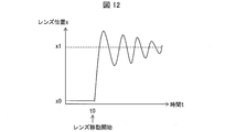
図12に示すように、レンズを高速で初期の位置x0から目的の位置x1へ移動させた場合、バネに起因する共振振動が発生することが知られている。この目的の位置x1で発生するアクチュエータの振動が許容レベル以下に減衰するまでに時間がかかり、実質上は高速駆動することができない。
ここで、アクチュエータを駆動する信号を適切に設定することで、アクチュエータの共振振動を抑えることは可能である。生産ライン等の調整段階で各カメラのアクチュエータの共振周波数を算出できれば、各アクチュエータの共振振動を抑えることが可能となる。しかし、そのためには、アクチュエータの共振周波数の個体ばらつきを正確に把握する必要がある。
特許文献1のカメラモジュールでは、図13に示すように、アクチュエータ111は、アクチュエータ駆動部140からの指示によりレンズ110を目的の位置に移動する。撮像素子131は撮像素子駆動部132からの指示により、レンズ110が透過した像を撮像し、信号処理部133は上記撮像された画像を処理する。そして、特許文献1のカメラモジュールでは変位センサ112を設けておく。特許文献1のカメラモジュールでは、レンズ110を目的の位置まで移動させたときに生じるアクチュエータ111の共振振動を変位センサ112によって観測し、当該観測した共振振動から、アクチュエータ111の共振周波数を算出する。
特許文献1では、変位センサ112からの信号に基づいてアクチュエータの共振周波数を算出している。しかし、変位センサを取り付けて共振周波数を測定するには、高い精度を有する。また変位センサを生産ラインで導入するにはコストがかかる。
本発明は、上記課題を解決するためになされたもので、その目的は、高い精度や高コスト化を要求されず、アクチュエータの共振周波数を算出することである。
上記の課題を解決するために、本発明の一態様に係る共振周波数算出装置は、アクチュエータにより移動させたレンズを所定の位置で停止させたとき、上記アクチュエータに生じる振動の共振周波数を算出する共振周波数算出装置であって、上記アクチュエータを駆動させる駆動信号を、異なる駆動周波数で複数回、上記アクチュエータに出力するアクチュエータ駆動部と、上記異なる駆動周波数の駆動信号により、合焦位置とは異なる第1の位置から合焦位置である第2の位置へ複数回、上記レンズを移動して得られた被写体像の撮像画像を複数取得する撮像画像取得部と、上記複数の撮像画像のそれぞれのコントラスト値を算出するコントラスト値算出部と、上記複数の撮像画像のうち、上記コントラスト値が最も高い撮像画像を得るために上記アクチュエータを駆動させた上記駆動信号の駆動周波数の算出に使用した共振周波数を算出する共振周波数算出部とを備える。
上記の課題を解決するために、本発明の一態様に係る共振周波数算出方法は、アクチュエータにより移動させたレンズを所定の位置で停止させたとき、上記アクチュエータに生じる振動の共振周波数を算出する共振周波数算出方法であって、上記アクチュエータを駆動させる駆動信号を、異なる駆動周波数で複数回、上記アクチュエータに出力するステップと、上記異なる駆動周波数の駆動信号により、上記レンズを、合焦位置とは異なる第1の位置から合焦位置である第2の位置へ複数回移動させ、被写体像の撮像画像を複数取得するステップと、上記複数の撮像画像のそれぞれのコントラスト値を算出するステップと、上記複数の撮像画像のうち、上記コントラスト値が最も高い撮像画像を得るために上記アクチュエータを駆動させた上記駆動信号の駆動周波数の算出に使用した共振周波数を算出するステップとを有する。
上記の課題を解決するために、本発明の一態様に係る共振周波数算出方法は、アクチュエータにより移動させたレンズを所定の位置で停止させたとき、上記アクチュエータに生じる振動の共振周波数を算出する共振周波数算出方法であって、上記アクチュエータを駆動させる駆動信号を、異なる駆動周波数で複数回、上記アクチュエータに出力するステップと、上記異なる駆動周波数の駆動信号により、上記レンズを、合焦位置とは異なる第1の位置から合焦位置である第2の位置へ複数回移動させ、被写体像の撮像画像を複数取得するステップと、上記複数の撮像画像のそれぞれのコントラスト値を算出するステップと、上記複数の撮像画像のうち、上記コントラスト値が最も高い撮像画像を得るために上記アクチュエータを駆動させた上記駆動信号の駆動周波数の算出に使用した共振周波数を算出するステップとを有する。
本発明の一態様によれば、高い精度や高コスト化を要求されず、アクチュエータの共振周波数を算出するという効果を奏する。
〔実施形態1〕
(撮像装置1の構成)
図1は実施の形態1に係る撮像装置1の構成を表す図である。図1に示すように、撮像装置1は、共振周波数算出装置5と、レンズ10と、アクチュエータ11と、絞り機構12と、記憶部17と、撮像部30とを備えている。共振周波数算出装置5は、絞り機構制御部13と、コントラスト値算出部(コントラスト値記憶部)14と、共振周波数算出部15と、アクチュエータ駆動部(露光開始指示部)40とを備える。撮像部30は、撮像素子31と、撮像素子駆動制御部32と、撮像画像取得部33とを備えている。なお、絞り機構12及び絞り機構制御部13を省略し、他にレンズ10から撮像素子31への露光量を調整する機構を備えていてもよい。
(撮像装置1の構成)
図1は実施の形態1に係る撮像装置1の構成を表す図である。図1に示すように、撮像装置1は、共振周波数算出装置5と、レンズ10と、アクチュエータ11と、絞り機構12と、記憶部17と、撮像部30とを備えている。共振周波数算出装置5は、絞り機構制御部13と、コントラスト値算出部(コントラスト値記憶部)14と、共振周波数算出部15と、アクチュエータ駆動部(露光開始指示部)40とを備える。撮像部30は、撮像素子31と、撮像素子駆動制御部32と、撮像画像取得部33とを備えている。なお、絞り機構12及び絞り機構制御部13を省略し、他にレンズ10から撮像素子31への露光量を調整する機構を備えていてもよい。
アクチュエータ11は、レンズ10を保持し、アクチュエータ駆動部40からの駆動信号に基づきレンズ10を移動させることでレンズ10と撮像素子31との相対位置を移動させる。アクチュエータ11はレンズ10を移動させる動力源としての駆動部と、当該駆動部からの動力を付勢しレンズ10に伝達することでレンズ10を移動させる付勢部材とを備える。アクチュエータ11は、当該付勢部材を備えることに起因し、レンズ10を目的の位置まで高速で移動させたとき共振振動を生じる。アクチュエータ11の上記駆動部の一例はVCMであり、上記付勢部材の一例はバネである。
絞り機構12は、レンズ10から撮像素子31へ入射する光量を調整するために、絞り機構制御部13からの指示により開閉する絞りを有する。絞り機構12は、例えば、レンズ10と、撮像素子31との間に配されている。
撮像素子31は、レンズ10からの透過光を受光面から入射し、光電変換し電気信号として出力する。一例として撮像素子31はCCD又はCMOS等の受光素子である。撮像素子駆動制御部32は撮像素子31の駆動を制御する。撮像画像取得部33は撮像素子31から出力された電気信号から撮像画像を取得する。
共振周波数算出装置5は、アクチュエータ11により移動させたレンズ10を所定の位置で停止させたとき、アクチュエータ11に生じる振動の共振周波数を算出する。
コントラスト値算出部14は、撮像画像取得部33が取得した撮像画像のコントラスト値を算出する。そして、コントラスト値算出部14は、当該撮像画像を得るためにアクチュエータ11を駆動させた駆動信号の駆動周波数を算出するために使用した共振周波数と、上記算出したコントラスト値とを対応づけて記憶部17に記憶する。
共振周波数算出部15は、記憶部17に記憶されている複数のコントラスト値の大小を比較し、最も値が高いコントラスト値を特定し、当該特定した最も値が高いコントラスト値と対応づけて記憶されている共振周波数を特定することで、アクチュエータ11の固有の共振周波数を算出する。共振周波数算出部15が上記特定した最も値が高いコントラスト値と対応づけて記憶部17に記憶されている共振周波数は、当該コントラスト値を得た撮像画像を得るためにアクチュエータ11を駆動させた駆動信号の駆動周波数を、駆動周波数算出部41が算出するために使用した共振周波数である。
アクチュエータ駆動部40は駆動周波数算出部41を備える。なお、駆動周波数算出部41はアクチュエータ駆動部40の外部に設けられていてもよく、さらに、共振周波数算出装置5の外部に設けられていてもよい。アクチュエータ駆動部40は、アクチュエータ11の駆動を制御するものである。駆動周波数算出部41は、アクチュエータ駆動部40が共振周波数算出部15から共振周波数を取得すると、当該共振周波数を予め定められた整数倍し駆動周波数を算出する。アクチュエータ駆動部40は、駆動周波数算出部41が算出した駆動周波数を有する駆動信号を生成し、当該生成した駆動信号をアクチュエータ11へ出力することでアクチュエータ11を駆動する。アクチュエータ駆動部40は、アクチュエータ11を駆動させる駆動信号を、異なる駆動周波数で複数回、アクチュエータ11に出力することでアクチュエータ11の駆動を制御する。アクチュエータ駆動部40には、複数回、駆動周波数が異なる駆動信号をアクチュエータ11に出力する繰り返し回数iが記憶される。
アクチュエータ11の駆動信号の駆動周波数は概ね、アクチュエータ11にバネが使用されている場合、そのバネ定数によって決まる。この駆動周波数が決まればアクチュエータ11の共振周波数も決まる。しかし、現在使用中のアクチュエータ11の固有の共振周波数は、アクチュエータ11の個体間やレンズ10の位置等によりバラつきがある。
そこで、アクチュエータ駆動部40は、アクチュエータ11の共振周波数のバラつきの上限から算出される上限の駆動周波数から、アクチュエータ11の共振周波数のバラつきの下限から算出される駆動周波数まで、等間隔で駆動信号を生成し、それぞれの駆動信号によってアクチュエータ11を駆動する。また、アクチュエータ駆動部40は、アクチュエータ11を駆動した駆動信号の駆動周波数を算出するために使用した共振周波数を記憶部17に記憶する。
記憶部17には、撮像画像取得部33が取得した撮像画像を得るためにアクチュエータ11の駆動に用いた駆動信号の駆動周波数を算出するために使用した共振周波数と、上記撮像画像からコントラスト値算出部14が算出したコントラスト値とが対応付けて記憶される。
撮像装置1では、レンズ10の位置調整のためにフォーカス調整用画像を用いる。図5はフォーカス調整用画像の一例を示す図である。図5に示すように、フォーカス調整用画像9は、白と黒とのエッジが明確であり、そのエッジ部分のコントラストが高い画像を用いることが好ましい。図5のフォーカス調整用画像9は、一例として、白領域と黒領域とが放射状に配されたジーメンススターチャートを用いている。なお、フォーカス調整用画像9はジーメンススターチャートに限らず、フォーカスエリアの図形が左右対称でありコントラストが高い画像であればよい。
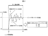
図2は、撮像装置1のレンズの共振と露光期間とを表す図である。図2の縦軸は撮像装置1におけるレンズ10の位置を表し、横軸は時間を表している。
位置x0は撮像装置1におけるレンズ10の移動開始位置(初期の位置)であり、合焦位置ではない。一方、位置x1はフォーカス調整用画像9に対するレンズ10の合焦位置である。すなわち、位置x1はフォーカス調整用画像9に対しレンズ10のピントが合っている位置である。この位置x1の算出方法の一例としてはオートフォーカスを挙げることができる。
アクチュエータ駆動部40が、アクチュエータ11を通じてレンズ10を、初期の位置x0から目的の合焦位置である位置x1へ移動させると、位置x1においてアクチュエータ11が共振することにより、レンズ10も位置x1を中心に共振することになる。図2の領域Aや領域Bに示すように、レンズ10の位置が位置x1から遠くなるほど画像が酷くボケている状態となる。
このアクチュエータ駆動部40が、アクチュエータ11を通じてレンズ10を、位置x0から位置x1へ移動させるために、アクチュエータ11に出力する駆動信号の駆動周波数が、アクチュエータ11の固有の共振周波数に近ければ近いほどレンズ10を目的の位置x1へ移動させたときに位置x1において生じるアクチュエータ11の共振を抑えることができ、その結果、位置x1におけるレンズ10の共振を抑えることができる。
図2において、振動y1は、アクチュエータ11の固有の共振周波数と近い振動周波数から算出された駆動周波数の駆動信号でアクチュエータ11を駆動させたときの位置x1におけるレンズ10の振動を表している。振動y1は位置x1を中心とする振動が小さく、振動が収束する時間が短くて済む。
振動y2は、アクチュエータ11の駆動信号の駆動周波数が、アクチュエータ11の固有の共振周波数と遠い振動周波数から算出された場合の位置x1におけるレンズ10の振動を表している。振動y2は、振動y1と比べて振動が大きい。領域A・Bに示すように、レンズ10の位置が、位置x1から離れている程、画像のピントが酷くボケている状態である。振動y2は振動y1と比べて振動が収束するまでの時間が長い。
そこで、レンズ10の移動開始位置である位置x0からレンズ10を移動させるときの時間を時間t0とすると、この時間t0から、合焦位置である位置x1へレンズ10を移動させて所定期間経過後の時間ttまで絞り機構12の絞りを開き、露光することでフォーカス調整用画像9の撮像画像を得る。
この得られた撮像画像のコントラスト値を取得し、コントラスト値が高い場合は、露光時間中に画像がボケている状態の期間が少ないと判断できる。この結果、アクチュエータ11を駆動した駆動信号の駆動周波数を算出するために使用した振動周波数がアクチュエータ11の固有の共振周波数に近いと推定することができる。逆に、露光期間T0(時間t0~時間ttまでの期間)中に得られた撮像画像のコントラスト値が低い場合は、露光期間T0中に画像がボケている状態の期間が多いと判断できる。この結果、アクチュエータ11を駆動した駆動信号の駆動周波数を算出するために使用した振動周波数がアクチュエータ11の固有の共振周波数から大きく異なると推定することができる。
コントラスト値を得る方法は種々の方法を挙げることができる。一例として、上記撮像画像の輝度信号にハイパスフィルタ等のフィルタ処理をすることで上記撮像画像の高周波成分を抽出し、当該抽出した高周波成分の積分データを生成することで上記撮像画像のコントラスト値を得ることができる。
図3は、撮像画像から得られたコントラスト値と、アクチュエータの振動周波数との関係を表す図である。このアクチュエータの振動周波数からアクチュエータの駆動信号の駆動周波数が得られる。アクチュエータ11の駆動信号の駆動周波数はアクチュエータ11にバネが使用されている場合、当該バネのバネ定数によって決まる。
図3に示すように、アクチュエータ11の駆動信号の駆動周波数を、例えば、アクチュエータ11の個体間及び位置による共振振動のバラつきの、上限から得られる上限の振動周波数から、下限から得られる下限の振動周波数まで、約等間隔の測定ステップaごとに振っていく。一例として、アクチュエータの共振周波数は60Hz程度であり、バラつきは±15Hz程度である。
そして、その測定ステップa毎のそれぞれから得られた振動周波数でアクチュエータ11を駆動させたときに得られるそれぞれの撮像画像のコントラスト値を比較していく。そして、そのそれぞれの撮像画像のコントラスト値が最も高い値Chとなったときに、そのコントラスト値を得た撮像画像を撮像するために使用したアクチュエータ11の駆動周波数Nを得た振動周波数が、現在使用しているアクチュエータ11固有の共振周波数であるものと推定することができる。
このように得られたアクチュエータ11の共振周波数を整数倍することで、アクチュエータ11の駆動信号の駆動周波数を得る。一例として、アクチュエータ11の共振周波数は60Hzであり、アクチュエータ11の駆動信号の駆動周波数は、共振周波数の2倍の120Hz程度である。なお、アクチュエータ11の駆動信号の駆動周波数は、共振周波数の整数倍であればよい。倍率は予め決めておけばよい。
(撮像装置1の処理の流れ)
図4は撮像装置1の処理の流れを表すフローチャートである。まず、撮像装置1で、フォーカス調整用画像9に対しレンズ10が合焦する位置x1を取得しておく。この合焦する位置x1を得る方法は、一例としてオートフォーカスを挙げることができる。このオートフォーカスの方法は、コントラストAFや位相差AF等、種々の方法を取りえる。
図4は撮像装置1の処理の流れを表すフローチャートである。まず、撮像装置1で、フォーカス調整用画像9に対しレンズ10が合焦する位置x1を取得しておく。この合焦する位置x1を得る方法は、一例としてオートフォーカスを挙げることができる。このオートフォーカスの方法は、コントラストAFや位相差AF等、種々の方法を取りえる。
そして、共振周波数の測定を開始すると(S10)、アクチュエータ駆動部40は、繰り返し回数i=0にセットし(S11)、共振周波数f=j+a*iにセットする(S12)。jは初期値、aは測定ステップである。駆動周波数算出部41は共振周波数fを整数倍することで駆動周波数を算出する。そして、アクチュエータ駆動部40は共振周波数fを、当該共振周波数fを特定する情報と共に記憶部17に記憶し、さらに、上記算出された駆動周波数で駆動信号を生成し、当該生成した駆動信号をアクチュエータ11に出力する。
そして、アクチュエータ11は当該駆動信号によりレンズ10を初期の位置x0から合焦する位置x1へ移動させる(S13)。また、アクチュエータ駆動部40がアクチュエータ11へ駆動信号を出力すると、絞り機構制御部13は絞り機構12の絞りを開く。これにより、レンズ10の移動開始と同時にレンズ10から撮像素子31へ光が入射し露光が開始される(S14)。そして、撮像素子31は、レンズ10から受光した光を電気信号へ変換し、当該変換した電気信号を撮像画像取得部33へ出力する。撮像画像取得部33は当該電気信号から撮像画像を取得し、当該撮像画像をコントラスト値算出部14へ出力する。コントラスト値算出部14は上記撮像画像のコントラスト値を取得し(S15)、当該算出したコントラスト値を、上記特定する情報によって特定されている共振周波数fと対応付けて記憶部17に記憶する。これにより、コントラスト値算出部14は、上記コントラスト値と、当該コントラスト値を得るために駆動させたアクチュエータの駆動信号の駆動周波数を得た共振周波数fとを対応付けて記憶部17に記憶する。
そして、コントラスト値算出部14はコントラスト値を記憶部17に記憶した旨の情報をアクチュエータ駆動部40に出力する。アクチュエータ駆動部40は、コントラスト値算出部14からコントラスト値を記憶部17に記憶した旨の情報を取得すると、アクチュエータ11にレンズ位置を戻すための駆動信号を出力する。これにより、アクチュエータ11はレンズ10を位置x1から元の初期の位置x0へ移動させる(S16)。
次に、アクチュエータ駆動部40は、iが所定回数か否かを判定し(S17)、S17にて、アクチュエータ駆動部40は、iが所定回数で無いと判定すると(S17のNo)、i=i+1にセットする(S19)。そして、S12に戻り、アクチュエータ駆動部40は、共振周波数f=j+a*iにセットする。そしてS13以降の処理を順に行う。
一方、S17にて、アクチュエータ駆動部40は、iが所定回数であると判定すると(S17のYES)、iが所定回数である旨の情報を共振周波数算出部15へ出力する。共振周波数算出部15は、iが所定回数である旨の情報を取得すると、記憶部17を参照し、記憶部17に記憶されたコントラスト値のうち最も高いコントラスト値と対応付けて記憶されている共振周波数fをアクチュエータ11の固有の共振周波数として算出する(S18)。そして、共振周波数算出部15は、当該共振周波数fをアクチュエータ駆動部40へ出力する。駆動周波数算出部41は、上記共振周波数fを予め決められた整数倍することで駆動周波数を算出し、アクチュエータ駆動部40は上記駆動周波数を有する駆動信号を生成し、当該駆動信号でアクチュエータ11を駆動する。
以上のように、共振周波数算出装置5は、アクチュエータ11を駆動させる駆動信号を、異なる駆動周波数で複数回、アクチュエータ11に出力するアクチュエータ駆動部40と、異なる駆動周波数の駆動信号により、レンズ10を、アクチュエータ11が初期位置である位置x0から合焦位置である位置x1へ複数回移動させることで得られたフォーカス調整用画像9の撮像画像を複数取得する撮像画像取得部33と、上記複数の撮像画像のそれぞれのコントラスト値を算出するコントラスト値算出部14と、上記複数の撮像画像のうちコントラスト値が最も高い撮像画像を得るためにアクチュエータ11を駆動させた駆動信号の駆動周波数の算出に使用した共振周波数を算出する共振周波数算出部15とを備える。
これにより、コントラスト値算出部14が算出したコントラスト値から、レンズ10を移動させたアクチュエータ11の共振周波数を得ることができる。このため、例えば、共振周波数算出装置5を搭載した撮像装置1の生産ラインにて、変位センサ等によりレンズ10の振動を測定したり、アクチュエータ11のVCMの巻線の電流もしくは電圧を観測するセンサを使用したりする必要がなく、生産コスト増加を防止することができる。また、製品である撮像装置1等に共振周波数算出装置5を搭載することにより、経年変化等によるピントのズレを修正する事が可能となる。
また、コントラスト値算出部14は、撮像素子31が撮像し撮像画像取得部33が取得する上記撮像画像を得るためにアクチュエータ11に用いた駆動信号の駆動周波数の算出に使用した共振周波数fと、上記撮像画像からコントラスト値算出部14が算出したコントラスト値とを対応付けて記憶部17に記憶させる。これによると、記憶部17に記憶されている複数のコントラスト値のうち最も値が高いコントラスト値を特定することで、アクチュエータ11の固有の共振周波数を特定することができる。
また、共振周波数算出装置5は、レンズ10から撮像素子31への入射光量を調整することで、撮像素子31の露光時間を調整する絞り機構12に対して、アクチュエータ11がレンズ10の位置x0から上記第2の位置への移動を開始したとき露光を開始させる絞り機構制御部13を備えている。このように、絞り機構制御部13からの指示を受けた絞り機構12はレンズ10が位置x0から移動を開始したと同時に露光を開始するため、露光を開始するための制御が容易になる。なお、撮像装置1では、絞り機構12及び絞り機構制御部13は必須の構成ではなく、他に、例えばカメラ機能付き携帯電話端末に用いられているような撮像素子31への入射光量を調整する機能を有していてもよい。
また、撮像装置1は、共振周波数算出装置5と、共振周波数算出部15が算出した共振周波数を整数倍することでアクチュエータ11の駆動信号の駆動周波数を算出する駆動周波数算出部41とを備えているため、高い精度や高コスト化を要求されず、アクチュエータ11の固有の共振周波数を算出することができる。なお、駆動周波数算出部41は、共振周波数算出装置5の内部又は外部の何れに設けられていてもよい。共振周波数算出装置5は、例えば、撮像装置1として、デジタルカメラ、カメラ機能付き携帯電話、カメラ機能付きのタブレット、ノート型パーソナルコンピュータ等、薄型及び小型のカメラ機能付きの種々の電子機器に適用可能である。
〔実施形態2〕
説明の便宜上、実施形態1にて説明した部材と同じ機能を有する部材については、同じ符号を付記し、その説明を省略する。図6は実施形態2の撮像装置2の構成を表す図である。図7は撮像装置2においてレンズの共振とレンズ移動後に露光を開始している様子を表す図である。
説明の便宜上、実施形態1にて説明した部材と同じ機能を有する部材については、同じ符号を付記し、その説明を省略する。図6は実施形態2の撮像装置2の構成を表す図である。図7は撮像装置2においてレンズの共振とレンズ移動後に露光を開始している様子を表す図である。
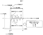
図6に示すように撮像装置2は、撮像装置1にタイマー18を備えた構成である。図7に示すように、撮像装置2では、レンズ10が目的の位置x1へ移動完了してから露光を開始する。
これにより、レンズ10移動中の撮像画像のコントラスト値の影響を少なくし、精度良く共振周波数を求めることが可能となる。ここでのレンズ10の移動完了時の時間t1は、位置x0からのレンズ移動開始時間t0に、レンズ10が位置x0から位置x1へ至るまでに要するレンズ移動期間T1を加えて算出される時間とする。撮像装置2では、絞り機構12は、時間t0からレンズ移動期間T1経過時の時間t1から時間ttまでの露光期間T2だけ撮像画像を得るために撮像素子を露光する。
レンズ移動期間T1の算出方法の一例としては、アクチュエータ11の駆動に使用した駆動周波数から算出される共振周波数と、レンズ10の移動距離とから算出することが可能である。
図8は撮像装置2の処理の流れを表すフローチャートである。図8に示す撮像装置2のフローチャートは、図4を用いて説明した撮像装置1のフローチャートにおけるS14をS24に置き換えたものである。
S10~S12の処理後、S13にて、アクチュエータ11は当該駆動信号によりレンズ10を初期の位置x0から合焦する位置x1へ移動を開始させる。アクチュエータ駆動部40がアクチュエータ11へ駆動信号を出力すると、絞り機構制御部13はタイマー18を参照し、アクチュエータ駆動部40がアクチュエータ11へ駆動信号を出力してからレンズ移動期間T1経過時に絞り機構12の絞りを開く。これにより、レンズ10の移動開始からレンズ移動期間T1経過時、レンズ10から撮像素子31へ光が入射し露光が開始される(S24)。この後、S15以降の処理を行う。
このように共振周波数算出装置5では、絞り機構制御部13は、レンズ10から撮像素子31への入射光量を調整することで撮像素子31の露光時間を調整する絞り機構12に対して、アクチュエータ11がレンズ10の位置x0から位置x1への移動が完了したとき露光を開始させる。このため、レンズ10移動中のコントラスト値変動の影響を少なくし、精度よくアクチュエータ11固有の共振周波数を算出することが可能となる。
〔実施形態3〕
図9は実施形態3に係る撮像装置3の構成を表す図である。撮像装置3は、撮像装置1から、共振周波数算出装置5を共振周波数算出装置7へ変更し、記憶部17を記憶部17bへ変更した構成である。共振周波数算出装置7は、共振周波数算出装置5から共振周波数算出部15を共振周波数算出部15bへ変更し、アクチュエータ駆動部40をアクチュエータ駆動部40bへ変更した構成である。アクチュエータ駆動部40bは駆動周波数算出部41と、オフセット制御部42と、繰り返し回数管理部43とを備える。
図9は実施形態3に係る撮像装置3の構成を表す図である。撮像装置3は、撮像装置1から、共振周波数算出装置5を共振周波数算出装置7へ変更し、記憶部17を記憶部17bへ変更した構成である。共振周波数算出装置7は、共振周波数算出装置5から共振周波数算出部15を共振周波数算出部15bへ変更し、アクチュエータ駆動部40をアクチュエータ駆動部40bへ変更した構成である。アクチュエータ駆動部40bは駆動周波数算出部41と、オフセット制御部42と、繰り返し回数管理部43とを備える。
オフセット制御部42には、オフセット値offsetが記憶されている。繰り返し回数管理部43は、繰り返し回数i・kそれぞれの記憶領域を有する。繰り返し回数管理部43は、繰り返し回数i・kそれぞれの繰り返すべき所定回数が記憶されている。
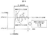
図10は、撮像装置3のレンズの共振と露光期間とを表す図である。アクチュエータ11のバネ要素による共振周波数は、バネの固体バラつきだけでなく、レンズ10位置によって変わる。なお、下記では、繰り返し回数kを用いオフセット値をoffset=b*kと定義しているが、本実施の形態では、繰り返し回数kが1のときについて説明する。
図10に示すように共振周波数算出装置7では、レンズ移動開始位置をオフセット値offset+位置x0(第1の位置、第3の位置)とし、合焦位置をオフセット値offset+位置x1(第2の位置、第4の位置)とする。レンズ10の移動開始位置であるオフセット値offset+位置x0からレンズ10を移動させるときの時間を時間t0とすると、この時間t0から、合焦位置であるオフセット値offset+位置x1へレンズ10を移動させて所定期間経過後の時間ttまでの露光期間T0だけ絞り機構12の絞りを開き、露光することでフォーカス調整用画像9の撮像画像を得る。
共振周波数算出装置7では、このオフセット値offsetを順次変更することで、レンズ10のレンズ位置を順次変更し、それぞれのレンズ位置に対する共振周波数を算出する。これにより、レンズ位置が変わってもそれぞれの位置での共振周波数の算出が可能となる。
図11は、実施形態3の撮像装置3の処理の流れを表すフローチャートである。
まず、撮像装置3で、フォーカス調整用画像9に対しレンズ10が合焦する位置x1+オフセット値offsetを取得しておく。この合焦する位置x1+オフセット値offsetを得る方法は、一例としてオートフォーカスを挙げることができる。このオートフォーカスの方法は、コントラストAFや位相差AF等、種々の方法を取りえる。
撮像装置3は、共振周波数の測定を開始すると(S10)、アクチュエータ駆動部40bは、繰り返し回数管理部43に記憶されている繰り返し回数kをk=0とセットする(S31)。次に、S11で、アクチュエータ駆動部40bは、繰り返し回数管理部43に記憶されている繰り返し回数iをi=0とセットする。そして、S12を経て、アクチュエータ駆動部40bはオフセット制御部42に記憶されているオフセット値offset=b*kと変更する(S32)。bは測定stepである。これにより、オフセット制御部42は、レンズ10の移動開始位置であるオフセット値offset+位置x0及び合焦位置であるオフセット値offset+位置x1を算出する(S33)。
さらに、駆動周波数算出部41は共振周波数fを整数倍することで駆動周波数を算出する。そして、アクチュエータ駆動部40bは共振周波数(第1の共振周波数、第2の共振周波数)fを、当該共振周波数fを特定する情報と共に記憶部17bに記憶し、さらに、上記算出された駆動周波数及び上記オフセット値offsetの情報を含む駆動信号を生成し、当該生成した駆動信号をアクチュエータ11に出力する。
そして、アクチュエータ11は当該駆動信号によりレンズ10を位置x0+オフセット値offsetから位置x1+オフセット値offsetへ移動させる(S34)。また、レンズ10の移動開始と同時に絞り機構制御部13が絞り機構12の絞りを開くことでレンズ10から撮像素子31への露光を開始し(S14)、次に、コントラスト値算出部14は撮像素子31が撮像した撮像画像のコントラスト値を取得し(S15)、当該算出したコントラスト値を、上記特定する情報によって特定されている共振周波数fと対応付けて記憶部17bに記憶する。そして、コントラスト値算出部14がコントラスト値を記憶部17bに記憶した旨の情報をアクチュエータ駆動部40bに出力すると、アクチュエータ駆動部40bはアクチュエータ11にレンズ位置を戻すための駆動信号を出力する。これにより、アクチュエータ11はレンズ10を位置x1+オフセット値offsetから、元の位置x0+オフセット値offsetへ移動させる(S35)。次に、アクチュエータ駆動部40bは、繰り返し回数管理部43を参照し繰り返し回数iが所定回数か否かを判定し(S17)、iが所定回数で無い場合(S17のNo)、i=i+1にセットする(S19)。そして、S12に戻り、アクチュエータ駆動部40bは、共振周波数f=j+a*iにセットする。そしてS32以降の処理を順に行う。
一方、S17にて、アクチュエータ駆動部40bは、繰り返し回数管理部43の繰り返し回数iが所定回数であると判定すると(S17のYES)、共振周波数算出部15bは、記憶部17bを参照し、記憶部17bに記憶されたコントラスト値のうち最も高いコントラスト値と対応付けて記憶されている共振周波数fをアクチュエータ11の固有の共振周波数として算出する(S36)。そして共振周波数算出部15は、当該共振周波数fを、現在オフセット制御部42に記憶されている位置x1+オフセット値offsetの位置と対応付けて記憶部17bに記憶する(S37)。次に、アクチュエータ駆動部40bは、繰り返し回数管理部43を参照し、繰り返し回数kが所定回数か否かを判定し(S38)、kが所定回数で無い場合(S38のNo)、k=k+1にセットする(S39)。そして、S11に戻り、繰り返し回数管理部43の繰り返し回数i=0にセットし、S12以降の処理を進める。一方、S37で、kが所定回数である場合(S37のYES)、共振周波数の算出動作を終了する。
この後、レンズ10の移動指示をアクチュエータ駆動部40bが取得すると、S37で記憶部17bに記憶したレンズ位置(位置x1+オフセット値offset)のうち、移動指示を受けたレンズ10の移動位置と最も近いレンズ位置と対応付けて記憶されている共振周波数fを選択し、当該選択した共振周波数fを取得し、駆動周波数算出部41は当該共振周波数fを整数倍することで駆動周波数を得る。そして、アクチュエータ駆動部40bは算出した駆動周波数を有する駆動信号を生成し、当該駆動信号でアクチュエータ11を駆動する。
以上のように、共振周波数算出装置7は、位置x0+オフセット値offset及び位置x1+オフセット値offsetそれぞれからオフセット値offsetを変更した後の位置x0+オフセット値offset(第3の位置)及び位置x1+オフセット値offset(第4の位置)を得るオフセット制御部42をさらに備える。そして、共振周波数算出部15が、共振周波数f(第1共振周波数)を算出すると、アクチュエータ駆動部40は、再度、上記駆動信号を、上記異なる駆動周波数で複数回、アクチュエータ11に出力する。そして、撮像画像取得部33は、アクチュエータ駆動部40が上記異なる駆動周波数の駆動信号によりレンズ10を位置x0+オフセット値offsetから位置x1+オフセット値offsetへ複数回移動させて得られた複数の被写体像の撮像画像(第2の撮像画像群)を取得する。そして、コントラスト値算出部14は、上記複数の被写体像の撮像画像のそれぞれの撮像画像のコントラスト値(第2のコントラスト値群)を算出し記憶部17bに記憶する。次に、共振周波数算出部15は、記憶部17bに記憶された上記複数の被写体像の撮像画像のうち、コントラスト値が最も高い撮像画像を得るためにアクチュエータ11を駆動させた駆動信号の駆動周波数の算出に使用した共振周波数(第2の共振周波数)を記憶部17bから特定することで算出する。これにより、レンズ10の位置に合ったアクチュエータ11の共振周波数を得ることができ、より正確にアクチュエータの共振周波数を算出することができる。
なお、上記では、繰り返し回数kが1のときについて説明したが、kが1以上の整数の場合は、以下のように表現することもできる。すなわち、上記第1の位置及び上記第3の位置は第mの位置(mは正の奇数)、上記第2の位置及び上記第4の位置は第m+1の位置、上記第1の共振周波数及び上記第2の共振周波数は第nの共振周波数(nは1以上の整数)、上記第2の撮像画像群は第pの撮像画像群(pは2以上の整数)、上記第2のコントラスト値群は第pのコントラスト値群と、それぞれ表現してもよい。
〔ソフトウェアによる実現例〕
共振周波数算出装置5の制御ブロック(特にコントラスト値算出部14、共振周波数算出部15およびアクチュエータ駆動部40)は、集積回路(ICチップ)等に形成された論理回路(ハードウェア)によって実現してもよいし、CPU(Central Processing Unit)を用いてソフトウェアによって実現してもよい。
共振周波数算出装置5の制御ブロック(特にコントラスト値算出部14、共振周波数算出部15およびアクチュエータ駆動部40)は、集積回路(ICチップ)等に形成された論理回路(ハードウェア)によって実現してもよいし、CPU(Central Processing Unit)を用いてソフトウェアによって実現してもよい。
後者の場合、共振周波数算出装置5は、各機能を実現するソフトウェアであるプログラムの命令を実行するCPU、上記プログラムおよび各種データがコンピュータ(またはCPU)で読み取り可能に記録されたROM(Read Only Memory)または記憶装置(これらを「記録媒体」と称する)、上記プログラムを展開するRAM(Random Access Memory)などを備えている。そして、コンピュータ(またはCPU)が上記プログラムを上記記録媒体から読み取って実行することにより、本発明の目的が達成される。上記記録媒体としては、「一時的でない有形の媒体」、例えば、テープ、ディスク、カード、半導体メモリ、プログラマブルな論理回路などを用いることができる。また、上記プログラムは、該プログラムを伝送可能な任意の伝送媒体(通信ネットワークや放送波等)を介して上記コンピュータに供給されてもよい。なお、本発明は、上記プログラムが電子的な伝送によって具現化された、搬送波に埋め込まれたデータ信号の形態でも実現され得る。
〔まとめ〕
本発明の態様1に係る共振周波数算出装置は、アクチュエータにより移動させたレンズを所定の位置で停止させたとき、上記アクチュエータに生じる振動の共振周波数を算出する共振周波数算出装置であって、上記アクチュエータを駆動させる駆動信号を、異なる駆動周波数で複数回、上記アクチュエータに出力するアクチュエータ駆動部と、上記異なる駆動周波数の駆動信号により、合焦位置とは異なる第1の位置から合焦位置である第2の位置へ複数回、上記レンズを移動して得られた被写体像の撮像画像を複数取得する撮像画像取得部と、上記複数の撮像画像のそれぞれのコントラスト値を算出するコントラスト値算出部と、上記複数の撮像画像のうち、上記コントラスト値が最も高い撮像画像を得るために上記アクチュエータを駆動させた上記駆動信号の駆動周波数の算出に使用した共振周波数を算出する共振周波数算出部とを備えることを特徴とする。
本発明の態様1に係る共振周波数算出装置は、アクチュエータにより移動させたレンズを所定の位置で停止させたとき、上記アクチュエータに生じる振動の共振周波数を算出する共振周波数算出装置であって、上記アクチュエータを駆動させる駆動信号を、異なる駆動周波数で複数回、上記アクチュエータに出力するアクチュエータ駆動部と、上記異なる駆動周波数の駆動信号により、合焦位置とは異なる第1の位置から合焦位置である第2の位置へ複数回、上記レンズを移動して得られた被写体像の撮像画像を複数取得する撮像画像取得部と、上記複数の撮像画像のそれぞれのコントラスト値を算出するコントラスト値算出部と、上記複数の撮像画像のうち、上記コントラスト値が最も高い撮像画像を得るために上記アクチュエータを駆動させた上記駆動信号の駆動周波数の算出に使用した共振周波数を算出する共振周波数算出部とを備えることを特徴とする。
上記構成により、高い精度や高コスト化を要求されず、アクチュエータの共振周波数を算出することができる。
本発明の態様2に係る共振周波数算出装置は、上記アクチュエータが上記レンズの上記第1の位置から上記第2の位置への移動を開始したときに露光を開始させる、又は、上記アクチュエータが上記レンズの上記第1の位置から上記第2の位置への移動が完了したときに露光を開始させる露光開始指示部を備えていてもよい。
上記構成によると、上記露光開始指示部の指示によりレンズが第1の位置から移動を開始すると同時に露光を開始するため、露光を開始するための制御が容易になる。
また、上記アクチュエータが上記レンズの上記第1の位置から上記第2の位置への移動が完了したときに露光を開始させることで、レンズ移動中のコントラスト値変動の影響を少なくし、精度よく共振周波数を算出することが可能となる。
本発明の態様3に係る共振周波数算出装置は、上記態様1又は2において、上記第1の位置及び上記第2の位置それぞれから所定の距離ずらした第3の位置及び第4の位置を得るオフセット制御部をさらに備え、上記共振周波数算出部が、上記共振周波数である第1共振周波数を算出すると、上記アクチュエータ駆動部は、再度、上記駆動信号を、上記異なる駆動周波数で複数回、上記アクチュエータに出力し、上記撮像画像取得部は、上記異なる駆動周波数の駆動信号により、上記レンズを、上記第3の位置から上記第4の位置へ複数回移動させ、被写体像の撮像画像が複数からなる第2の撮像画像群を取得し、上記コントラスト値算出部は、上記第2の撮像画像群のそれぞれの撮像画像のコントラスト値である第2のコントラスト値群を算出し、上記共振周波数算出部は、上記第2の撮像画像群のうち、上記コントラスト値が最も高い撮像画像を得るために上記アクチュエータを駆動させた上記駆動信号の駆動周波数の算出に使用した共振周波数である第2の共振周波数を算出する。上記構成によると、レンズ位置に合ったアクチュエータの共振周波数を得ることができるため、より正確に共振周波数を算出することができる。
本発明の態様4に係る撮像装置は、上記態様1~3に記載の共振周波数算出装置と、上記共振周波数算出部が算出した共振周波数を整数倍することで上記アクチュエータの駆動信号の駆動周波数を算出する駆動周波数算出部を備えていてもよい。上記構成によると、高い精度や高コスト化を要求されず、アクチュエータの共振周波数を算出することができる撮像装置を得ることができる。
本発明の態様5に係る共振周波数算出装置は、上記態様1~3において、上記撮像画像を得るために上記アクチュエータに用いた駆動信号の駆動周波数の算出に使用した共振周波数と、上記撮像画像から上記コントラスト値算出部が算出したコントラスト値と、を対応付けて記憶部に記憶させるコントラスト値記憶部を備えていてもよい。
上記構成により、記憶部に記憶された最も値が高いコントラスト値を特定することで、アクチュエータの固有の共振周波数を得ることができる。
本発明の態様6に係る共振周波数算出方法は、アクチュエータにより移動させたレンズを所定の位置で停止させたとき、上記アクチュエータに生じる振動の共振周波数を算出する共振周波数算出方法であって、上記アクチュエータを駆動させる駆動信号を、異なる駆動周波数で複数回、上記アクチュエータに出力するステップと、上記異なる駆動周波数の駆動信号により、上記レンズを、合焦位置とは異なる第1の位置から合焦位置である第2の位置へ複数回移動させ、被写体像の撮像画像を複数取得するステップと、上記複数の撮像画像のそれぞれのコントラスト値を算出するステップと、上記複数の撮像画像のうち、上記コントラスト値が最も高い撮像画像を得るために上記アクチュエータを駆動させた上記駆動信号の駆動周波数の算出に使用した共振周波数を算出するステップとを有することを特徴とする。これにより、態様1と同様の効果を奏する。
本発明の各態様に係る共振周波数算出装置は、コンピュータによって実現してもよく、この場合には、コンピュータを上記共振周波数算出装置が備える各手段として動作させることにより上記共振周波数算出装置をコンピュータにて実現させる共振周波数算出装置の共振周波数算出プログラム、およびそれを記録したコンピュータ読み取り可能な記録媒体も、本発明の範疇に入る。
本発明は上述した各実施形態に限定されるものではなく、請求項に示した範囲で種々の変更が可能であり、異なる実施形態にそれぞれ開示された技術的手段を適宜組み合わせて得られる実施形態についても本発明の技術的範囲に含まれる。さらに、各実施形態にそれぞれ開示された技術的手段を組み合わせることにより、新しい技術的特徴を形成することができる。
本発明は、アクチュエータの共振周波数を算出する共振周波数算出装置、撮像装置、共振周波数算出プログラムおよび共振周波数算出方法に利用することができる。
1・2・3 撮像装置
5・7 共振周波数算出装置
9 フォーカス調整用画像
10 レンズ
11 アクチュエータ
12 絞り機構
13 絞り機構制御部
14 コントラスト値算出部
15・15b 共振周波数算出部(コントラスト値記憶部)
17・17b 記憶部
31 撮像素子
32 撮像素子駆動制御部
33 撮像画像取得部
40・40b アクチュエータ駆動部
41 駆動周波数算出部
42 オフセット制御部
5・7 共振周波数算出装置
9 フォーカス調整用画像
10 レンズ
11 アクチュエータ
12 絞り機構
13 絞り機構制御部
14 コントラスト値算出部
15・15b 共振周波数算出部(コントラスト値記憶部)
17・17b 記憶部
31 撮像素子
32 撮像素子駆動制御部
33 撮像画像取得部
40・40b アクチュエータ駆動部
41 駆動周波数算出部
42 オフセット制御部
Claims (6)
- アクチュエータにより移動させたレンズを所定の位置で停止させたとき、上記アクチュエータに生じる振動の共振周波数を算出する共振周波数算出装置であって、
上記アクチュエータを駆動させる駆動信号を、異なる駆動周波数で複数回、上記アクチュエータに出力するアクチュエータ駆動部と、
上記異なる駆動周波数の駆動信号により、合焦位置とは異なる第1の位置から合焦位置である第2の位置へ複数回、上記レンズを移動して得られた被写体像の撮像画像を複数取得する撮像画像取得部と、
上記複数の撮像画像のそれぞれのコントラスト値を算出するコントラスト値算出部と、
上記複数の撮像画像のうち、上記コントラスト値が最も高い撮像画像を得るために上記アクチュエータを駆動させた上記駆動信号の駆動周波数の算出に使用した共振周波数を算出する共振周波数算出部とを備えることを特徴とする共振周波数算出装置。 - 上記アクチュエータが上記レンズの上記第1の位置から上記第2の位置への移動を開始したときに露光を開始させる、又は、上記アクチュエータが上記レンズの上記第1の位置から上記第2の位置への移動が完了したときに露光を開始させる露光開始指示部を備えていることを特徴とする請求項1に記載の共振周波数算出装置。
- 上記第1の位置及び上記第2の位置それぞれから所定の距離ずらした第3の位置及び第4の位置を得るオフセット制御部をさらに備え、
上記共振周波数算出部が、上記共振周波数である第1共振周波数を算出すると、
上記アクチュエータ駆動部は、再度、上記駆動信号を、上記異なる駆動周波数で複数回、上記アクチュエータに出力し、
上記撮像画像取得部は、上記異なる駆動周波数の駆動信号により、上記レンズを、上記第3の位置から上記第4の位置へ複数回移動させ、被写体像の撮像画像が複数からなる第2の撮像画像群を取得し、
上記コントラスト値算出部は、上記第2の撮像画像群のそれぞれの撮像画像のコントラスト値である第2のコントラスト値群を算出し、
上記共振周波数算出部は、上記第2の撮像画像群のうち、上記コントラスト値が最も高い撮像画像を得るために上記アクチュエータを駆動させた上記駆動信号の駆動周波数の算出に使用した共振周波数である第2の共振周波数を算出することを特徴とする請求項1又は2に記載の共振周波数算出装置。 - 請求項1~3の何れか1項に記載の共振周波数算出装置と、
上記共振周波数算出部が算出した共振周波数を整数倍することで上記アクチュエータの駆動信号の駆動周波数を算出する駆動周波数算出部とを備えていることを特徴とする撮像装置。 - 請求項1~3のいずれか1項に記載の共振周波数算出装置としてコンピュータを機能させるための共振周波数算出プログラムであって、コンピュータを上記各部として機能させるための共振周波数算出プログラム。
- アクチュエータにより移動させたレンズを所定の位置で停止させたとき、上記アクチュエータに生じる振動の共振周波数を算出する共振周波数算出方法であって、
上記アクチュエータを駆動させる駆動信号を、異なる駆動周波数で複数回、上記アクチュエータに出力するステップと、
上記異なる駆動周波数の駆動信号により、上記レンズを、合焦位置とは異なる第1の位置から合焦位置である第2の位置へ複数回移動させ、被写体像の撮像画像を複数取得するステップと、
上記複数の撮像画像のそれぞれのコントラスト値を算出するステップと、
上記複数の撮像画像のうち、上記コントラスト値が最も高い撮像画像を得るために上記アクチュエータを駆動させた上記駆動信号の駆動周波数の算出に使用した共振周波数を算出するステップとを有することを特徴とする共振周波数算出方法。
Applications Claiming Priority (2)
| Application Number | Priority Date | Filing Date | Title |
|---|---|---|---|
| JP2013-191915 | 2013-09-17 | ||
| JP2013191915 | 2013-09-17 |
Publications (1)
| Publication Number | Publication Date |
|---|---|
| WO2015041101A1 true WO2015041101A1 (ja) | 2015-03-26 |
Family
ID=52688752
Family Applications (1)
| Application Number | Title | Priority Date | Filing Date |
|---|---|---|---|
| PCT/JP2014/073809 Ceased WO2015041101A1 (ja) | 2013-09-17 | 2014-09-09 | 共振周波数算出装置、撮像装置、共振周波数算出プログラムおよび共振周波数算出方法 |
Country Status (1)
| Country | Link |
|---|---|
| WO (1) | WO2015041101A1 (ja) |
Citations (3)
| Publication number | Priority date | Publication date | Assignee | Title |
|---|---|---|---|---|
| JP2000162096A (ja) * | 1998-11-30 | 2000-06-16 | Kurimoto Ltd | 土木建築構造物の振動測定方法 |
| JP2003161889A (ja) * | 2001-11-27 | 2003-06-06 | Nikon Corp | 格子照明顕微鏡 |
| JP2006162523A (ja) * | 2004-12-09 | 2006-06-22 | Ricoh Co Ltd | 周期可動物の速度測定装置及び変位測定装置 |
-
2014
- 2014-09-09 WO PCT/JP2014/073809 patent/WO2015041101A1/ja not_active Ceased
Patent Citations (3)
| Publication number | Priority date | Publication date | Assignee | Title |
|---|---|---|---|---|
| JP2000162096A (ja) * | 1998-11-30 | 2000-06-16 | Kurimoto Ltd | 土木建築構造物の振動測定方法 |
| JP2003161889A (ja) * | 2001-11-27 | 2003-06-06 | Nikon Corp | 格子照明顕微鏡 |
| JP2006162523A (ja) * | 2004-12-09 | 2006-06-22 | Ricoh Co Ltd | 周期可動物の速度測定装置及び変位測定装置 |
Similar Documents
| Publication | Publication Date | Title |
|---|---|---|
| US20240056681A1 (en) | Camera body for receiving first and second image plane transfer coefficients | |
| JP5406830B2 (ja) | カメラシステム | |
| JP5535080B2 (ja) | カメラシステム | |
| JP6341691B2 (ja) | 像振れ補正装置およびその制御方法、光学機器、撮像装置 | |
| US7697831B1 (en) | Auto-focus with lens vibration | |
| US8412036B2 (en) | Imaging apparatus and method of controlling the apparatus | |
| US20110110656A1 (en) | Camera system and image forming apparatus | |
| US20110164868A1 (en) | Method and apparatus for applying multi-autofocusing (af) using contrast af | |
| JP2012137739A (ja) | 撮像装置及びレンズユニット | |
| US20180176454A1 (en) | Focus adjustment apparatus, imaging apparatus, focus adjustment method, and recording medium storing a focus adjustment program thereon | |
| WO2018173902A1 (ja) | 交換レンズ及びその制御方法、撮像装置、並びに、カメラシステム | |
| JP5645486B2 (ja) | カメラシステム及びこれに用いられるレンズユニット、カメラユニット | |
| US20200259992A1 (en) | Imaging apparatus, lens apparatus, camera system, and control method of imaging apparatus | |
| JP2014017713A (ja) | レンズユニットおよび撮像装置 | |
| US20110164867A1 (en) | Digital photographing apparatus and method that apply high-speed multi-autofocusing (af) | |
| WO2015041101A1 (ja) | 共振周波数算出装置、撮像装置、共振周波数算出プログラムおよび共振周波数算出方法 | |
| JP5984883B2 (ja) | レンズユニット、撮像装置、及びそれらの制御方法 | |
| JP2012255824A (ja) | レンズ鏡筒、光学機器 | |
| JP2016071150A (ja) | 交換レンズ装置、撮像装置および制御プログラム | |
| JP2011022404A (ja) | 撮像装置及びその制御方法 | |
| JP5602774B2 (ja) | 撮像装置およびその制御方法、レンズユニットおよびその制御方法 | |
| JP6924089B2 (ja) | 撮像装置およびその制御方法 | |
| JP2016090982A (ja) | 自動焦点調整装置 | |
| JP2012123051A (ja) | 撮像装置及びレンズユニット | |
| JP2013125159A (ja) | レンズ装置および撮像装置 |
Legal Events
| Date | Code | Title | Description |
|---|---|---|---|
| 121 | Ep: the epo has been informed by wipo that ep was designated in this application |
Ref document number: 14846262 Country of ref document: EP Kind code of ref document: A1 |
|
| NENP | Non-entry into the national phase |
Ref country code: DE |
|
| 122 | Ep: pct application non-entry in european phase |
Ref document number: 14846262 Country of ref document: EP Kind code of ref document: A1 |
|
| NENP | Non-entry into the national phase |
Ref country code: JP |