WO2015037644A1 - 充填装置および飲料の製造方法 - Google Patents
充填装置および飲料の製造方法 Download PDFInfo
- Publication number
- WO2015037644A1 WO2015037644A1 PCT/JP2014/074019 JP2014074019W WO2015037644A1 WO 2015037644 A1 WO2015037644 A1 WO 2015037644A1 JP 2014074019 W JP2014074019 W JP 2014074019W WO 2015037644 A1 WO2015037644 A1 WO 2015037644A1
- Authority
- WO
- WIPO (PCT)
- Prior art keywords
- filling
- liquid
- solid
- container
- nozzle
- Prior art date
- Legal status (The legal status is an assumption and is not a legal conclusion. Google has not performed a legal analysis and makes no representation as to the accuracy of the status listed.)
- Ceased
Links
Images


Classifications
-
- B—PERFORMING OPERATIONS; TRANSPORTING
- B65—CONVEYING; PACKING; STORING; HANDLING THIN OR FILAMENTARY MATERIAL
- B65B—MACHINES, APPARATUS OR DEVICES FOR, OR METHODS OF, PACKAGING ARTICLES OR MATERIALS; UNPACKING
- B65B43/00—Forming, feeding, opening or setting-up containers or receptacles in association with packaging
- B65B43/42—Feeding or positioning bags, boxes, or cartons in the distended, opened, or set-up state; Feeding preformed rigid containers, e.g. tins, capsules, glass tubes, glasses, to the packaging position; Locating containers or receptacles at the filling position; Supporting containers or receptacles during the filling operation
- B65B43/54—Means for supporting containers or receptacles during the filling operation
-
- B—PERFORMING OPERATIONS; TRANSPORTING
- B65—CONVEYING; PACKING; STORING; HANDLING THIN OR FILAMENTARY MATERIAL
- B65B—MACHINES, APPARATUS OR DEVICES FOR, OR METHODS OF, PACKAGING ARTICLES OR MATERIALS; UNPACKING
- B65B1/00—Packaging fluent solid material, e.g. powders, granular or loose fibrous material, loose masses of small articles, in individual containers or receptacles, e.g. bags, sacks, boxes, cartons, cans, or jars
- B65B1/04—Methods of, or means for, filling the material into the containers or receptacles
-
- B—PERFORMING OPERATIONS; TRANSPORTING
- B65—CONVEYING; PACKING; STORING; HANDLING THIN OR FILAMENTARY MATERIAL
- B65B—MACHINES, APPARATUS OR DEVICES FOR, OR METHODS OF, PACKAGING ARTICLES OR MATERIALS; UNPACKING
- B65B3/00—Packaging plastic material, semiliquids, liquids or mixed solids and liquids, in individual containers or receptacles, e.g. bags, sacks, boxes, cartons, cans, or jars
- B65B3/04—Methods of, or means for, filling the material into the containers or receptacles
-
- B—PERFORMING OPERATIONS; TRANSPORTING
- B65—CONVEYING; PACKING; STORING; HANDLING THIN OR FILAMENTARY MATERIAL
- B65B—MACHINES, APPARATUS OR DEVICES FOR, OR METHODS OF, PACKAGING ARTICLES OR MATERIALS; UNPACKING
- B65B65/00—Details peculiar to packaging machines and not otherwise provided for; Arrangements of such details
- B65B65/003—Packaging lines, e.g. general layout
-
- B—PERFORMING OPERATIONS; TRANSPORTING
- B65—CONVEYING; PACKING; STORING; HANDLING THIN OR FILAMENTARY MATERIAL
- B65B—MACHINES, APPARATUS OR DEVICES FOR, OR METHODS OF, PACKAGING ARTICLES OR MATERIALS; UNPACKING
- B65B2220/00—Specific aspects of the packaging operation
- B65B2220/14—Adding more than one type of material or article to the same package
-
- B—PERFORMING OPERATIONS; TRANSPORTING
- B65—CONVEYING; PACKING; STORING; HANDLING THIN OR FILAMENTARY MATERIAL
- B65B—MACHINES, APPARATUS OR DEVICES FOR, OR METHODS OF, PACKAGING ARTICLES OR MATERIALS; UNPACKING
- B65B39/00—Nozzles, funnels or guides for introducing articles or materials into containers or wrappers
- B65B39/14—Nozzles, funnels or guides for introducing articles or materials into containers or wrappers movable with a moving container or wrapper during filling or depositing
- B65B39/145—Nozzles, funnels or guides for introducing articles or materials into containers or wrappers movable with a moving container or wrapper during filling or depositing in an endless path
-
- B—PERFORMING OPERATIONS; TRANSPORTING
- B65—CONVEYING; PACKING; STORING; HANDLING THIN OR FILAMENTARY MATERIAL
- B65B—MACHINES, APPARATUS OR DEVICES FOR, OR METHODS OF, PACKAGING ARTICLES OR MATERIALS; UNPACKING
- B65B43/00—Forming, feeding, opening or setting-up containers or receptacles in association with packaging
- B65B43/42—Feeding or positioning bags, boxes, or cartons in the distended, opened, or set-up state; Feeding preformed rigid containers, e.g. tins, capsules, glass tubes, glasses, to the packaging position; Locating containers or receptacles at the filling position; Supporting containers or receptacles during the filling operation
- B65B43/54—Means for supporting containers or receptacles during the filling operation
- B65B43/60—Means for supporting containers or receptacles during the filling operation rotatable
Definitions
- the present invention relates to a filling device and a beverage production method, and more particularly to a filling device for filling a container with liquid and solid, and a beverage production method for filling a container with liquid and solid. is there.
- Patent Document 1 Japanese Patent Laid-Open No. 6-8996
- Patent Document 1 discloses filling a container with a beverage containing pulp yarn (pulp).
- This filling machine has a problem that it takes a long time to fill a beverage containing pulp.
- the present invention has been made to solve the above-described problems, and an object thereof is to provide a filling device and a beverage manufacturing method capable of filling a container with a liquid and a solid in a short time. Is.
- the filling device is a filling device that fills a container with liquid and solid in separate steps while the container is being transported, and the transport path has a linear path through which the container moves in a substantially straight line. A solid filling takes place in a linear path.
- the filling speed can be improved as compared with the case of filling them after mixing them. Furthermore, since the solid filling is performed in the linear path, it is possible to fill in a large amount at a high speed as compared with the case of filling the solid in the curved path. As a result, the container can be filled with liquid and solid in a short time.
- a curved path is provided in the transport path, and the liquid is filled in the curved path.
- the solid is filled after the liquid is filled.
- the method for producing a beverage according to the present invention is a method for producing a beverage in which a liquid and a solid are filled in separate processes while the container is being transported, and the container moves in a substantially straight line along the transport path. A straight path is provided, and solid filling is performed in the straight path.
- the container is filled with the liquid and the solid in separate steps, so that the filling speed can be improved as compared with the case of filling them after mixing them. Furthermore, since the solid filling is performed in the linear path, it is possible to fill in a large amount at a high speed as compared with the case of filling the solid in the curved path. As a result, the container can be filled with liquid and solid in a short time. Furthermore, since the solid is filled in the linear path, it is possible to prevent the centrifugal force from being applied to the solid during the filling of the solid. Thereby, it can prevent that solid adheres to the side wall of a filling path
- a beverage production method is a beverage production method comprising a step of filling a container with a liquid using a liquid filling nozzle and a step of filling a container with a solid using a solid filling nozzle.
- the liquid filling nozzle is driven so as to return from the predetermined position to the predetermined position along the conveyance path including the curved portion and the straight portion, and the step of filling the liquid includes the step of filling the liquid with the liquid filling nozzle.
- Filling the container with at least a part of the liquid to be filled from the liquid filling nozzle while moving the part, and the step of filling the solid is performed by the liquid filling nozzle being a straight portion in the transport path And filling the container with solids from the solid nozzle.
- FIG. 6 is a plan view showing a container flow in the filling device according to the first embodiment.
- FIG. 10 is a plan view showing a flow of containers in a filling device according to a second embodiment.
- FIG. 1 is a diagram for explaining each step in the method for producing a beverage according to the first embodiment.
- a container is first arrange
- Liquid is supplied to the container (step S10). Any liquid can be used as long as it is drinkable. Further, for example, a carbonated beverage in which a gas is dissolved in the liquid may be used. Further, the viscosity of the liquid is not particularly limited as long as the viscosity can be filled in the filling apparatus.
- the solid is supplied after the liquid is supplied.
- the present invention is not limited to this, and the liquid may be supplied after the solid is supplied.
- the solid may be of a size that can be drunk and can be supplied by a nozzle.
- the solid is not limited to those that remain in the liquid without being dissolved in the liquid, and may be those that are soluble in the liquid. Further, the solid may be a semi-liquid, such as a sol or gel.
- the container is removed from the filling device.
- the atmosphere in the step of filling the liquid and the solid may be in the air or in an inert gas.
- FIG. 2 is a plan view showing the flow of the container in the filling device according to the first embodiment.
- the filling device 1 has an elliptical table 2. Then, the container 5 moves along the transport path 100 around the periphery of the table 2.
- the conveyance path 100 includes curved paths 11 and 12 and linear paths 13 and 14.
- the filling device 1 includes a liquid filling unit 4 that fills a container 5 with a liquid and a solid filling unit 3 that fills the container 5 with a solid.
- the liquid filling unit 4 has a circular shape and is provided in the curved paths 11 and 12 of the table 2.
- the solid filling unit 3 is provided in the linear paths 13 and 14 of the table 2.
- a nozzle that can move in the circumferential direction fills the container 5 with liquid while moving on the curved paths 11 and 12 together with the container 5.
- the curved paths 11 and 12 need only be curved and do not necessarily have a circular shape. It is also possible to adopt a distorted shape with respect to the circular shape.
- the liquid filling unit 4 is provided in the curved paths 11 and 12, but the liquid filling unit 4 is not necessarily provided in the curved paths 11 and 12, and the linear conveyance path is not provided.
- a liquid filling unit 4 may be provided.
- the nozzle that can move in the linear direction fills the container 5 with the solid while moving on the linear paths 13 and 14 together with the container 5. Since the container 5 is filled with the solid while the nozzle moves on the linear paths 13 and 14, the centrifugal force is not applied to the nozzle and the solid passing through the nozzle is not clogged.
- two solid filling parts 3 are provided in one table 2, but the present invention is not limited to this, and one or more solid filling parts 3 may be provided in one table 2. Good.
- a step of sterilizing the container 5 may be provided prior to liquid filling and solid filling. Furthermore, a step of sterilizing after the liquid filling and the solid filling may be provided.
- the filling device 1 is a filling device 1 that fills the container 5 with liquid and solid in separate steps while the container is being transported, and the linear route 13 through which the container moves in a substantially straight line, 14 is provided, and solid filling is performed in a linear path.
- Various containers such as glass bottles, cans, PET bottles, and paper packs can be used as the containers 5 for filling liquids and solids.
- the container 5 In filling the container 5 with liquid and solid, the container 5 is supplied to the table 2 as indicated by the arrow 5a. The container 5 moves along the curved paths 11 and 12. At this time, the liquid filling unit 4 fills the container 5 with the liquid. The nozzle is inserted into the container 5 without stopping the container 5, and the liquid is supplied from the nozzle to the container 5.
- the container 5 filled with the liquid is sent to the straight paths 13 and 14.
- the solid is filled from the solid filling unit 3 into the container 5.
- the nozzle is inserted into the container 5 without stopping the container 5, and the solid is supplied from the nozzle to the container 5. If the solid is supplied, the container 5 is taken out from the table 2 as shown by the arrow 5b and sent to the subsequent process.
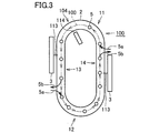
- FIG. 3 is a plan view showing the flow of the container in the filling device according to the second embodiment.
- filling device 110 has an elliptical table 2. Then, the container 5 moves along the transport path 100 around the periphery of the table 2.
- the conveyance path 100 includes curved paths 11 and 12 and linear paths 13 and 14.
- the filling device 110 includes a liquid filling nozzle 114 that fills the container 5 with liquid and a solid filling nozzle 113 that fills the container 5 with solid. Although only one liquid filling nozzle 114 is shown in FIG. 3, the filling device 110 includes a plurality of liquid filling nozzles along the transport path 100. A plurality of solid filling nozzles 113 are also arranged.
- Each liquid filling nozzle 114 is provided in the liquid filling unit 104 and connected to a liquid supply tank (not shown). Each liquid filling nozzle 114 moves on the upper side in the vertical direction of the table 2 along the transport path along the periphery of the table 2. The moving speed is adjusted to synchronize with the container 5 placed on the table 2.
- the liquid supply nozzle 114 descends to the container 5 in the curved paths 11 and 12 and approaches the opening of the container 5 and moves along the curved paths 11 and 12 together with the container 5 while maintaining this state. 5 is filled with liquid.
- the liquid filling may be continued not only in the curved paths 11 and 12 but also in the linear paths 13 and 14.
- the liquid filling nozzle 114 rises when the liquid supply is completed, and moves along the linear paths 13 and 14 while maintaining a distance from the container 5.
- the solid filling nozzle 113 is provided in the solid filling unit 3. After the liquid supply nozzle 114 rises, the solid filling nozzle 113 approaches the container 5, and moves along the linear paths 13 and 14 together with the container 5. Fill. Since the solid filling nozzle 113 is moved on the straight paths 13 and 14 and the container 5 is filled with the solid, the solid filling nozzle 113 is not subjected to centrifugal force and the solid passing through the solid filling nozzle 113 is not clogged. .
- two solid filling parts 3 are provided in one table 2, but the present invention is not limited to this, and one or more solid filling parts 3 may be provided in one table 2. Good.
- a step of sterilizing the container 5 may be provided prior to liquid filling and solid filling. Furthermore, a step of sterilizing after the liquid filling and the solid filling may be provided.
- the filling device 1 is a filling device 1 that fills the container 5 with liquid and solid in separate steps while the container is being transported, and the linear route 13 through which the container moves in a substantially straight line, 14 is provided, and solid filling is performed in a linear path.
- Various containers such as glass bottles, cans, PET bottles, and paper packs can be used as the containers 5 for filling liquids and solids.
- the container 5 In filling the container 5 with liquid and solid, the container 5 is supplied to the table 2 as indicated by the arrow 5a. The container 5 moves along the curved paths 11 and 12. At this time, the container 5 is filled with liquid from the liquid filling nozzle 114. The liquid filling nozzle 114 is inserted into the container 5 without being stopped, and the liquid is supplied from the liquid filling nozzle 114 to the container 5.
- the container 5 filled with the liquid is sent to the straight paths 13 and 14.
- the solid is filled from the solid filling unit 3 into the container 5.
- the solid filling nozzle 113 is inserted into the container 5 without being stopped, and the solid is supplied from the solid filling nozzle 113 to the container 5. If the solid is supplied, the container 5 is taken out from the table 2 as shown by the arrow 5b and sent to the subsequent process.
- the uniformity of the filled beverage is increased compared to the method of filling the liquid with the solid in the same step. That is, in the step of filling after mixing the liquid and the solid, since the solid is not necessarily uniformly dispersed in the mixed solution, the density, viscosity, and the like of the mixed solution are likely to be non-uniform. When such a mixed liquid is filled in the container 5, the density and viscosity of drinking filled in the container 5 tend to be uneven. Therefore, a uniform beverage can be produced by filling the liquid and the solid in separate steps. Furthermore, the filling speed can be improved by filling only the liquid and only the solid as compared with the method of filling the mixed liquid. Furthermore, although it is difficult to fill a container with a liquid and solid mixed fluid in a strictly constant amount, it is possible to fill a strictly constant amount by separately filling a solid and a liquid. .
- the step of filling the liquid is not necessarily performed in the curved paths 11 and 12, but by filling the liquid in the arc-shaped curved paths 11 and 12, the container 5 can be used at high speed using a general-purpose liquid filling machine. Can be filled with liquid.
- the present invention can be used in the fields of beverage filling devices and beverage production methods.
- 1,110 filling device 1,110 filling device, 2 table, 3 solid filling section, 4,104 liquid filling section, 5 container, 11,12 curved path, 13,14 linear path, 100 transport path.
Landscapes
- Engineering & Computer Science (AREA)
- Mechanical Engineering (AREA)
- Basic Packing Technique (AREA)
Abstract
短時間で容器に液体と固体とを充填することが可能な充填装置および飲料の製造方法を提供することを目的とする。容器(5)が搬送される間に容器に液体と固体とを別工程で充填する充填装置(1)であって、搬送経路(100)に、容器(5)がほぼ直線状に移動する直線状経路(13,14)が設けられ、直線状経路(13,14)において、固体の充填が行われる。
Description
この発明は、充填装置および飲料の製造方法に関して、より特定的には、容器に液体と固体とを充填する充填装置、および、容器に液体と固体とが充填された飲料の製造方法に関するものである。
従来、充填装置は、たとえば特開平6-8996号公報(特許文献1)に開示されている。
特許文献1では、果肉糸(パルプ)入りの飲料を容器に充填することが開示されている。
この充填機では、果肉入りの飲料を充填するために長時間が必要であるという問題があった。
そこで、この発明は上記の問題を解決するためになされたものであり、短時間で容器に液体と固体とを充填することが可能な充填装置および飲料の製造方法を提供することを目的とするものである。
この発明に従った充填装置は、容器が搬送される間に容器に液体と固体とを別工程で充填する充填装置であって、搬送経路に、容器がほぼ直線状に移動する直線状経路が設けられ、直線状経路において、固体の充填が行われる。
このように構成された充填装置においては、容器に液体と固体とを別工程で充填するため、これらを混合した後に充填する場合と比べて充填のスピードを向上させることができる。さらに、直線状経路において固体の充填が行われるため、曲線状経路において固体を充填する場合と比較して、大量に高速で充填することができる。その結果、短時間で容器に液体と固体とを充填することが可能となる。
好ましくは、搬送経路に曲線状経路が設けられ、曲線状経路において液体の充填が行われる。
好ましくは、液体を充填した後に固体の充填が行われる。
この発明に従った飲料の製造方法は、容器が搬送される間に容器に液体と固体とを別工程で充填する飲料の製造方法であって、搬送経路に、容器がほぼ直線状に移動する直線状経路が設けられ、直線状経路において固体の充填が行われる。
この発明に従った飲料の製造方法は、容器が搬送される間に容器に液体と固体とを別工程で充填する飲料の製造方法であって、搬送経路に、容器がほぼ直線状に移動する直線状経路が設けられ、直線状経路において固体の充填が行われる。
このように構成された飲料の製造方法では、容器に液体と固体とを別工程で充填するため、これらを混合した後に充填する場合と比べて充填のスピードを向上させることができる。さらに、直線状経路において固体の充填が行われるため、曲線状経路において固体を充填する場合と比較して、大量に高速で充填することができる。その結果、短時間で容器に液体と固体とを充填することが可能となる。さらに、直線状経路において固体の充填が行われるため、固体の充填時に固体に遠心力が加わることを防止できる。これにより、固体が充填経路の側壁に付着することを防止できる。その結果、定量の固体を1つの容器に確実に充填することが可能となる。
この発明に従った飲料の製造方法は、液体充填ノズルを用いて容器内に液体を充填する工程と、固体充填ノズルを用いて容器内に固体を充填する工程とを備えた飲料の製造方法であって、前記液体充填ノズルは、曲線部と直線部を含む搬送経路を辿って、所定位置から該所定位置へと戻るよう駆動され、前記液体を充填する工程は、前記液体充填ノズルが前記曲線部を移動中に、充填すべき液体の少なくとも一部を前記液体充填ノズルから前記容器内に充填することを含み、前記固体を充填する工程は、前記液体充填ノズルが前記搬送経路中の直線部を移動中に、前記固体ノズルから前記容器内に固体を充填することを含む。
以下、実施の形態に従った充填装置、およびそれを用いた飲料の製造方法について説明する。
<実施形態1>
(構成の説明)
図1は、実施の形態1に従った飲料の製造方法における各工程を説明するための図である。図1を参照して、飲料の製造方法では、まず、充填装置に容器が配置される。容器に液体を供給する(ステップS10)。液体としては飲用可能なものであればどのようなものであってもよい。さらに液体中に気体が溶解した、たとえば炭酸飲料であってもよい。さらに液体の粘度に関しては特に制限されるものではなく、充填装置において充填可能な粘度であればよい。
(構成の説明)
図1は、実施の形態1に従った飲料の製造方法における各工程を説明するための図である。図1を参照して、飲料の製造方法では、まず、充填装置に容器が配置される。容器に液体を供給する(ステップS10)。液体としては飲用可能なものであればどのようなものであってもよい。さらに液体中に気体が溶解した、たとえば炭酸飲料であってもよい。さらに液体の粘度に関しては特に制限されるものではなく、充填装置において充填可能な粘度であればよい。
容器に固体を供給する(ステップS20)。この例では液体を供給した後に固体を供給しているが、これに限られず固体を供給した後に液体を供給してもよい。固体としては、飲用可能で、かつ、ノズルにより供給できる程度の大きさのものであればよい。固体は液体に対して溶けずに液体中に残存するものに限られず、液体に溶けるものであってもよい。さらに、固体は、ゾル状またはゲル状などの、半液体であってもよい。
固体と液体との充填が終われば、容器が充填装置から取出される。液体と固体とを充填する工程の雰囲気は、大気中であってもよく、不活性ガス中であってもよい。
図2は、実施の形態1に従った充填装置における容器の流れを示す平面図である。図2を参照して、充填装置1は、楕円形状のテーブル2を有する。そして、テーブル2の周辺部を容器5が搬送経路100に沿って移動する。搬送経路100は曲線状経路11,12と直線状経路13,14を有する。
充填装置1は、容器5に液体を充填する液体充填部4と、容器5に固体を充填する固体充填部3とを有する。
液体充填部4は円形状であり、テーブル2の曲線状経路11,12に設けられる。これに対して、固体充填部3はテーブル2の直線状経路13,14に設けられる。
液体充填部4では円周方向に移動可能なノズルが容器5と共に曲線状経路11,12上を移動しながら容器5に液体を充填する。曲線状経路11,12は曲線であればよく、必ずしも円形状である必要は無い。円形状に対して歪んだ形状を採用することも可能である。なお、この実施の形態では液体充填部4は曲線状経路11,12に設けられているが、必ずしも曲線状経路11,12に液体充填部4が設けられる必要はなく、直線状の搬送経路に液体充填部4が設けられていてもよい。
固体充填部3では直線方向に移動可能なノズルが容器5と共に直線状経路13,14上を移動しながら容器5に固体を充填する。直線状経路13,14上をノズルが移動しながら容器5に固体を充填するため、ノズルに遠心力が加わらず、ノズル内を通過する固体が詰まることがない。
この実施の形態では1つのテーブル2に2つの固体充填部3が設けられているが、これに限られず1つ、または3つ以上の固体充填部3が1つのテーブル2に設けられていてもよい。
液体の充填および固体の充填に先だって、容器5を殺菌する工程が設けられていてもよい。さらに、液体の充填および固体の充填が終わった後に殺菌する工程が設けられていてもよい。充填装置1は、容器が搬送される間に容器5に液体と固体とを別工程で充填する充填装置1であって、搬送経路100に、容器がほぼ直線状に移動する直線状経路13,14が設けられ、直線状経路において、固体の充填が行われる。
液体および固体を充填するための容器5としては、ガラス瓶、缶、ペットボトル、紙パックなどの様々なものを採用することが可能である。
(充填工程の説明)
容器5への液体および固体の充填においては、矢印5aで示すように、テーブル2に容器5が供給される。容器5は曲線状経路11,12に沿って移動する。この時、液体充填部4が容器5に液体を充填する。容器5を停止されることなく容器5へノズルを差し込み、ノズルから容器5に液体を供給する。
容器5への液体および固体の充填においては、矢印5aで示すように、テーブル2に容器5が供給される。容器5は曲線状経路11,12に沿って移動する。この時、液体充填部4が容器5に液体を充填する。容器5を停止されることなく容器5へノズルを差し込み、ノズルから容器5に液体を供給する。
液体が充填された容器5は直線経路13,14へ送られる。直線状経路13,14において、固体充填部3から容器5へ固体が充填される。この工程においても、容器5を停止されることなく容器5へノズルを差し込み、ノズルから容器5に固体を供給する。固体が供給されれば、容器5は矢印5bで示すようにテーブル2から取出されて後の工程へ送られる。
<実施形態2>
図3は、実施の形態2に従った充填装置における容器の流れを示す平面図である。図3を参照して、充填装置110は、楕円形状のテーブル2を有する。そして、テーブル2の周辺部を容器5が搬送経路100に沿って移動する。搬送経路100は曲線状経路11,12と直線状経路13,14を有する。
図3は、実施の形態2に従った充填装置における容器の流れを示す平面図である。図3を参照して、充填装置110は、楕円形状のテーブル2を有する。そして、テーブル2の周辺部を容器5が搬送経路100に沿って移動する。搬送経路100は曲線状経路11,12と直線状経路13,14を有する。
充填装置110は、容器5に液体を充填する液体充填ノズル114と、容器5に固体を充填する固体充填ノズル113とを有する。図3では液体充填ノズル114を1つのみ記載しているが、充填装置110は液体充填ノズルを搬送経路100に沿って複数備えている。また、固体充填ノズル113も複数配置されている。
各液体充填ノズル114は液体充填部104に設けられ、液体供給タンク(図示せず)に接続されている。各液体充填ノズル114は、テーブル2の鉛直方向上側をテーブル2の周辺部に沿った搬送経路を移動する。移動スピードはテーブル2上に載置された容器5と同期するように調整されている。
液体供給ノズル114は曲線状経路11,12において容器5へと下降して容器5の開口部に接近し、この状態を保ったまま容器5とともに曲線状経路11,12に沿って移動し、容器5内に液体を充填する。液体の充填は曲線状経路11,12だけでなく直線状経路13,14においても引き続き行ってもよい。
液体充填ノズル114は液体の供給が終了すると上昇し、容器5と距離を保ったまま直線状経路13,14を移動する。
固体充填ノズル113は固体充填部3に設けられており、液体供給ノズル114が上昇した後、容器5へと接近して、容器5と共に直線状経路13,14上を移動しながら容器5に固体を充填する。直線状経路13,14上を固体充填ノズル113が移動しながら容器5に固体を充填するため、固体充填ノズル113に遠心力が加わらず、固体充填ノズル113内を通過する固体が詰まることがない。
この実施の形態では1つのテーブル2に2つの固体充填部3が設けられているが、これに限られず1つ、または3つ以上の固体充填部3が1つのテーブル2に設けられていてもよい。
液体の充填および固体の充填に先だって、容器5を殺菌する工程が設けられていてもよい。さらに、液体の充填および固体の充填が終わった後に殺菌する工程が設けられていてもよい。充填装置1は、容器が搬送される間に容器5に液体と固体とを別工程で充填する充填装置1であって、搬送経路100に、容器がほぼ直線状に移動する直線状経路13,14が設けられ、直線状経路において、固体の充填が行われる。
液体および固体を充填するための容器5としては、ガラス瓶、缶、ペットボトル、紙パックなどの様々なものを採用することが可能である。
(充填工程の説明)
容器5への液体および固体の充填においては、矢印5aで示すように、テーブル2に容器5が供給される。容器5は曲線状経路11,12に沿って移動する。この時、液体充填ノズル114から容器5に液体を充填する。容器5を停止されることなく容器5へ液体充填ノズル114を差し込み、液体充填ノズル114から容器5に液体を供給する。
容器5への液体および固体の充填においては、矢印5aで示すように、テーブル2に容器5が供給される。容器5は曲線状経路11,12に沿って移動する。この時、液体充填ノズル114から容器5に液体を充填する。容器5を停止されることなく容器5へ液体充填ノズル114を差し込み、液体充填ノズル114から容器5に液体を供給する。
液体が充填された容器5は直線経路13,14へ送られる。直線状経路13,14において、固体充填部3から容器5へ固体が充填される。この工程においても、容器5を停止されることなく容器5へ固体充填ノズル113を差し込み、固体充填ノズル113から容器5に固体を供給する。固体が供給されれば、容器5は矢印5bで示すようにテーブル2から取出されて後の工程へ送られる。
(作用・効果)
上記のように構成された充填装置、およびそれを用いた飲料の製造方法では、以下のような効果がある。
上記のように構成された充填装置、およびそれを用いた飲料の製造方法では、以下のような効果がある。
容器5に液体と固体とを別工程で充填しているため、同一工程で液体を固体とを充填するする方法と比較して、充填された飲料の均一性が高まる。すなわち、液体と固体とを混合した後に充填する工程では、混合液中には必ずしも固体が均一に分散していないため、混合液の密度、粘度などが不均一になりやすい。このような混合液を容器5に充填した場合には、容器5に充填された飲用の密度および粘度も不均一になりやすい。そのため、液体と固体とを別工程で充填することで、均一な飲料を製造することができる。さらに、混合液を充填する方法と比較して、液体のみ、および固体のみを充填することで、充填のスピードを向上させることができる。さらに、液体と固体との混合流体は厳密に一定量を容器に充填することが困難であるが、固体と液体とを別々に充填することで、厳密に一定量を充填することが可能となる。
固体を直線状経路13,14で充填しているため、充填経路において固体に遠心力が加わることを防止できる。固体の流れに遠心力が加わると、固体はノズルの壁面に当接し、固体の流れが著しく阻害される。この実施の形態では、固体の流れに遠心力が加わらないように直線状経路13,14で充填しているため、一定量の固体を確実に容器5に充填することが可能となる。その結果、飲料の品質を向上させることができる。
液体を充填する工程は必ずしも曲線状経路11,12で行う必要はないが、円弧形状の曲線状経路11,12において液体の充填を行うことで、汎用の液体充填機を用いて高速で容器5に液体を充填することが可能となる。
必ずしも先に液体を充填する必要はないが、先に容器5に液体を充填し、その後容器5に固体を充填することで、容器5内で固体が均一に分散しやすくなる。
今回開示された実施の形態はすべての点で例示であって制限的なものではないと考えられるべきである。本発明の範囲は上記した説明ではなくて請求の範囲によって示され、請求の範囲と均等の意味および範囲内でのすべての変更が含まれることが意図される。
この発明は、飲料の充填装置および飲料の製造方法の分野において用いることが可能である。
1,110 充填装置、2 テーブル、3 固体充填部、4,104 液体充填部、5 容器、11,12 曲線状経路、13,14 直線状経路、100 搬送経路。
Claims (9)
- 容器が搬送される間に容器に液体と固体とを別工程で充填する充填装置であって、
搬送経路を備え、
前記搬送経路に、容器がほぼ直線状に移動する直線状経路が設けられ、前記直線状経路において、固体の充填が行われる、充填装置。 - 前記搬送経路に曲線状経路が設けられ、前記曲線状経路において液体の充填が行われる、請求項1に記載の充填装置。
- 容器内に固体と液体を充填する充填装置であって、
液体を充填する液体充填ノズルと、
固体を充填する固体充填ノズルと、を備え、
前記液体充填ノズルは、曲線部と直線部を含む搬送経路を辿って、所定位置から該所定位置へと戻るよう駆動され、前記曲線部を移動中に、充填すべき液体の少なくとも一部を前記容器内に供給し、
前記固体充填ノズルは、前記液体充填ノズルが前記搬送経路中の直線部を移動中に、前記容器内に固体を充填する充填装置。 - 前記液体充填ノズルは、前記搬送経路を辿りながら、液体の充填時には前記容器に接近し、固体の充填時には前記容器から離れるよう駆動される請求項3に記載の充填装置。
- 液体を充填した後に固体の充填が行われる、請求項1から請求項4のいずれか1項に記載の充填装置。
- 容器が搬送される間に容器に液体を充填する工程と、
容器が搬送される間に容器に固体を充填する工程とを備えた飲料の製造方法であって、
搬送経路に、容器がほぼ直線状に移動する直線状経路が設けられ、前記固体を充填する工程では、前記直線状経路において固体の充填が行われる、飲料の製造方法。 - 前記搬送経路に曲線状経路が設けられ、前記液体を充填する工程では、前記曲線状経路において液体の充填が行われる、請求項6に記載の飲料の製造方法。
- 液体充填ノズルを用いて容器内に液体を充填する工程と、
固体充填ノズルを用いて容器内に固体を充填する工程とを備えた飲料の製造方法であって、
前記液体充填ノズルは、曲線部と直線部を含む搬送経路を辿って、所定位置から該所定位置へと戻るよう駆動され、
前記液体を充填する工程は、前記液体充填ノズルが前記曲線部を移動中に、充填すべき液体の少なくとも一部を前記液体充填ノズルから前記容器内に充填することを含み、
前記固体を充填する工程は、前記液体充填ノズルが前記搬送経路中の直線部を移動中に、前記固体ノズルから前記容器内に固体を充填することを含む、飲料の製造方法。 - 液体を充填した後に固体の充填が行われる、請求項6から請求項8のいずれか1項に記載の飲料の製造方法。
Applications Claiming Priority (2)
| Application Number | Priority Date | Filing Date | Title |
|---|---|---|---|
| JP2013188024 | 2013-09-11 | ||
| JP2013-188024 | 2013-09-11 |
Publications (2)
| Publication Number | Publication Date |
|---|---|
| WO2015037644A1 true WO2015037644A1 (ja) | 2015-03-19 |
| WO2015037644A9 WO2015037644A9 (ja) | 2015-05-07 |
Family
ID=52665744
Family Applications (1)
| Application Number | Title | Priority Date | Filing Date |
|---|---|---|---|
| PCT/JP2014/074019 Ceased WO2015037644A1 (ja) | 2013-09-11 | 2014-09-11 | 充填装置および飲料の製造方法 |
Country Status (2)
| Country | Link |
|---|---|
| TW (1) | TW201522200A (ja) |
| WO (1) | WO2015037644A1 (ja) |
Citations (9)
| Publication number | Priority date | Publication date | Assignee | Title |
|---|---|---|---|---|
| JPS5315431B2 (ja) * | 1974-02-28 | 1978-05-24 | ||
| JPH01139302A (ja) * | 1987-11-16 | 1989-05-31 | Sumitomo Bakelite Co Ltd | 液体充填方法 |
| DE3740942A1 (de) * | 1987-12-03 | 1989-06-15 | Quetsch Karl Heinz | Reihenlauf flaschenfuell- und verschliesskombination |
| JPH0995311A (ja) * | 1994-06-30 | 1997-04-08 | Ishii Shokuhin Kk | 袋詰包装機の包装袋の脱気方法 |
| JPH11127828A (ja) * | 1997-10-27 | 1999-05-18 | House Foods Corp | 容器入り低温殺菌食品の製造方法 |
| JPH11192077A (ja) * | 1998-01-05 | 1999-07-21 | House Foods Corp | 殺菌済み固液混合食品の製造方法 |
| JP2000344214A (ja) * | 1999-06-08 | 2000-12-12 | Nec Environment Eng Ltd | 流体包装装置 |
| JP4190692B2 (ja) * | 1999-03-11 | 2008-12-03 | 東洋自動機株式会社 | 物品の搬送装置 |
| JP2013511445A (ja) * | 2009-11-23 | 2013-04-04 | リドー マシーナリー インコーポレイテッド | 可溶性袋体の連続回転成形の改良 |
-
2014
- 2014-09-11 TW TW103131358A patent/TW201522200A/zh unknown
- 2014-09-11 WO PCT/JP2014/074019 patent/WO2015037644A1/ja not_active Ceased
Patent Citations (9)
| Publication number | Priority date | Publication date | Assignee | Title |
|---|---|---|---|---|
| JPS5315431B2 (ja) * | 1974-02-28 | 1978-05-24 | ||
| JPH01139302A (ja) * | 1987-11-16 | 1989-05-31 | Sumitomo Bakelite Co Ltd | 液体充填方法 |
| DE3740942A1 (de) * | 1987-12-03 | 1989-06-15 | Quetsch Karl Heinz | Reihenlauf flaschenfuell- und verschliesskombination |
| JPH0995311A (ja) * | 1994-06-30 | 1997-04-08 | Ishii Shokuhin Kk | 袋詰包装機の包装袋の脱気方法 |
| JPH11127828A (ja) * | 1997-10-27 | 1999-05-18 | House Foods Corp | 容器入り低温殺菌食品の製造方法 |
| JPH11192077A (ja) * | 1998-01-05 | 1999-07-21 | House Foods Corp | 殺菌済み固液混合食品の製造方法 |
| JP4190692B2 (ja) * | 1999-03-11 | 2008-12-03 | 東洋自動機株式会社 | 物品の搬送装置 |
| JP2000344214A (ja) * | 1999-06-08 | 2000-12-12 | Nec Environment Eng Ltd | 流体包装装置 |
| JP2013511445A (ja) * | 2009-11-23 | 2013-04-04 | リドー マシーナリー インコーポレイテッド | 可溶性袋体の連続回転成形の改良 |
Also Published As
| Publication number | Publication date |
|---|---|
| WO2015037644A9 (ja) | 2015-05-07 |
| TW201522200A (zh) | 2015-06-16 |
Similar Documents
| Publication | Publication Date | Title |
|---|---|---|
| EP2749501B1 (en) | A machine and a method for filling and labelling containers | |
| CN101723293B (zh) | 用于输送容器的设备 | |
| US9604252B2 (en) | Process for coating containers | |
| US10017370B2 (en) | Machine and method for filling containers | |
| EP3178781B1 (en) | Device, system, and bottling machine for introducing an additive fluid into a container | |
| WO2013094587A1 (ja) | 飲料充填方法及び装置 | |
| US11420779B2 (en) | Packaging method used in bag-feeding and packaging apparatus, and the bag-feeding and packaging apparatus | |
| JP6448913B2 (ja) | 発泡性液体を容器に充填するための方法および装置 | |
| CN108799821A (zh) | 持续的供气装置 | |
| WO2015037644A1 (ja) | 充填装置および飲料の製造方法 | |
| US20180273369A1 (en) | Beverage filling machine for filling cans having a heat exchange unit secured internally thereof with a liquid beverage | |
| JP6911532B2 (ja) | バッグインボックスのバッグ充填収納装置および方法 | |
| EP1838465B1 (en) | Unit for washing containers | |
| US12595163B2 (en) | Free-jet filling for a container with a multi-component filling product | |
| US20100199605A1 (en) | Method of forming and filling containers | |
| CN101717000B (zh) | 已灌装和密封的瓶装液态产品的防窜货包装工艺及系统 | |
| JP6617079B2 (ja) | エアコンベア | |
| US10273135B2 (en) | Machine for filling containers | |
| EP3026007A1 (en) | A filling head for filling containers | |
| CN207375726U (zh) | 一种玻璃瓶灌装机 | |
| CN206187378U (zh) | 新型颗粒定量灌装机 | |
| JP2016097998A (ja) | 液体用紙容器充填部キャリア | |
| JP2016141463A (ja) | 液体容器ホルダー | |
| ITPR20080045A1 (it) | Riempitrice rotativa e metodo per riempire contenitori con fluido | |
| JP2018012310A (ja) | 液体ブロー成形による容器製造方法 |
Legal Events
| Date | Code | Title | Description |
|---|---|---|---|
| 121 | Ep: the epo has been informed by wipo that ep was designated in this application |
Ref document number: 14844088 Country of ref document: EP Kind code of ref document: A1 |
|
| NENP | Non-entry into the national phase |
Ref country code: DE |
|
| 122 | Ep: pct application non-entry in european phase |
Ref document number: 14844088 Country of ref document: EP Kind code of ref document: A1 |
|
| NENP | Non-entry into the national phase |
Ref country code: JP |