WO2015037401A1 - 携帯端末 - Google Patents
携帯端末 Download PDFInfo
- Publication number
- WO2015037401A1 WO2015037401A1 PCT/JP2014/071708 JP2014071708W WO2015037401A1 WO 2015037401 A1 WO2015037401 A1 WO 2015037401A1 JP 2014071708 W JP2014071708 W JP 2014071708W WO 2015037401 A1 WO2015037401 A1 WO 2015037401A1
- Authority
- WO
- WIPO (PCT)
- Prior art keywords
- mobile terminal
- antenna
- user
- sensor
- antennas
- Prior art date
- Legal status (The legal status is an assumption and is not a legal conclusion. Google has not performed a legal analysis and makes no representation as to the accuracy of the status listed.)
- Ceased
Links
Images











Classifications
-
- H—ELECTRICITY
- H04—ELECTRIC COMMUNICATION TECHNIQUE
- H04B—TRANSMISSION
- H04B1/00—Details of transmission systems, not covered by a single one of groups H04B3/00 - H04B13/00; Details of transmission systems not characterised by the medium used for transmission
- H04B1/38—Transceivers, i.e. devices in which transmitter and receiver form a structural unit and in which at least one part is used for functions of transmitting and receiving
- H04B1/3827—Portable transceivers
- H04B1/3833—Hand-held transceivers
- H04B1/3838—Arrangements for reducing RF exposure to the user, e.g. by changing the shape of the transceiver while in use
-
- H—ELECTRICITY
- H04—ELECTRIC COMMUNICATION TECHNIQUE
- H04B—TRANSMISSION
- H04B7/00—Radio transmission systems, i.e. using radiation field
- H04B7/02—Diversity systems; Multi-antenna system, i.e. transmission or reception using multiple antennas
- H04B7/04—Diversity systems; Multi-antenna system, i.e. transmission or reception using multiple antennas using two or more spaced independent antennas
- H04B7/06—Diversity systems; Multi-antenna system, i.e. transmission or reception using multiple antennas using two or more spaced independent antennas at the transmitting station
- H04B7/0602—Diversity systems; Multi-antenna system, i.e. transmission or reception using multiple antennas using two or more spaced independent antennas at the transmitting station using antenna switching
-
- H—ELECTRICITY
- H04—ELECTRIC COMMUNICATION TECHNIQUE
- H04B—TRANSMISSION
- H04B7/00—Radio transmission systems, i.e. using radiation field
- H04B7/02—Diversity systems; Multi-antenna system, i.e. transmission or reception using multiple antennas
- H04B7/04—Diversity systems; Multi-antenna system, i.e. transmission or reception using multiple antennas using two or more spaced independent antennas
- H04B7/08—Diversity systems; Multi-antenna system, i.e. transmission or reception using multiple antennas using two or more spaced independent antennas at the receiving station
- H04B7/0802—Diversity systems; Multi-antenna system, i.e. transmission or reception using multiple antennas using two or more spaced independent antennas at the receiving station using antenna selection
- H04B7/0834—Diversity systems; Multi-antenna system, i.e. transmission or reception using multiple antennas using two or more spaced independent antennas at the receiving station using antenna selection based on external parameters, e.g. subscriber speed or location
Definitions
- the present invention relates to a portable terminal that includes a plurality of antennas and performs wireless communication, and relates to a technique for switching antennas used for wireless communication.
- Mobile terminals that wirelessly communicate with other devices using a plurality of antennas are widely used. In such a portable terminal, if the user covers the surface close to the antenna with a hand, the communication performance deteriorates. These portable terminals switch antennas to be used from among a plurality of antennas.
- Patent Document 1 discloses a technique for optimizing the diversity effect and reducing the adverse effect of the human body on the antenna characteristics and the SAR (Synthetic Aperture Radar) value in a portable wireless terminal.
- SAR Synthetic Aperture Radar
- Patent Document 1 states that “whether the terminal is in an open state (open state) or in a folded state (closed state) (open / closed state); The first, second, and third antennas 21, 22, depending on whether they are in a so-called talk position state or in a use hold state held in the user's hand, for example, during data communication. Two of the three antennas are selected and determined, and one of them is determined as a transmission / reception antenna, and the other is determined as a reception-only antenna ”(paragraph 0019 of Patent Document 1). However, when the user is holding the portable wireless terminal, there is a possibility that the periphery of the feeding point of the antenna is covered by the user's hand.
- An object of the present invention is to provide a technique for appropriately selecting an antenna to be used for wireless communication when a mobile terminal includes a plurality of antennas.
- a mobile terminal that wirelessly communicates with a communication device.
- the mobile terminal is provided with a plurality of antennas, a speaker for calling, a sensor provided in the vicinity of the speaker, which outputs a signal according to the distance between the speaker and the user's head, and an antenna switching operation for wireless communication.
- a communication interface for wirelessly communicating with a communication device using an antenna switched by the control of the control means.
- the control unit is configured to detect a gripping state of the mobile terminal by the user based on a contact position between the mobile terminal and the user, and a predetermined distance between the speaker and the user's head according to a signal output from the sensor.
- a plurality of antennas based on the detected gripping state when the determination unit determines whether or not the speaker is close to the following and the determination unit determines that the speaker and the user's head are not close to each other.
- the distance from the user's head among the plurality of antennas is large.
- a selection unit that selects at least one antenna based on the length.
- the mobile terminal it is possible to select an antenna with good communication performance from among a plurality of antennas and reduce the amount of radio waves emitted to the human body.
- FIG. 4 is a diagram for explaining a region of a main surface of the mobile terminal 1.
- FIG. It is a figure which shows the state in which the portable terminal 1 was hold
- 2 is a diagram illustrating a hardware configuration of a mobile terminal 1.
- FIG. 3 is a diagram for describing a functional configuration of a mobile terminal 1.
- FIG. 4 is a flowchart for explaining a flow of processing in the mobile terminal 1.
- 10 is a flowchart for explaining details of a process in step S4 in FIG. 9. It is a figure for demonstrating the movable area
- FIG. 1 is a diagram for explaining a schematic configuration of a mobile terminal 1 according to an embodiment of the present invention.
- FIG. 1A is a front view of the mobile terminal 1.
- FIG. 1B is a rear view of the mobile terminal 1.
- FIG. 1C is a side view of the mobile terminal 1.
- FIG. 1D is a cross-sectional view taken along the line II in FIG.
- the mobile terminal 1 includes a touch screen 108 and operation keys 105 on the main surface.
- the touch screen 108 includes a display and a touch panel.
- the portable terminal 1 is provided with side touch sensors 110a, 110b, 110c, and 110d on each side.
- the mobile terminal 1 includes the side surface touch sensors 110 a, 110 b, 110 c, and 110 d on the surface of the housing 10.
- Each of the side surface touch sensors 110a, 110b, 110c, and 110d can be configured by a capacitive sensor, for example.
- the touch panel may be adapted for hover. If the mobile terminal 1 is a narrow bezel terminal, the electric field also circulates to the side surface of the housing. Therefore, the mobile terminal 1 is provided with a hover-compatible touch panel so that the finger or hand contact position on the side surface of the housing Can be detected.
- the side touch sensor 110 may include four side touch sensors 110a, 110b, 110c, and 110d.
- the mobile terminal 1 includes a camera 107 and a back touch sensor 109 on the back. Similar to the side touch sensor 110, the back surface touch sensor 109 can be constituted by, for example, a capacitive sensor.
- the mobile terminal 1 includes a plurality of antennas 121 and 122 and a plurality of electronic circuits 131, 132, 133, and 134 in the housing 10.
- the electronic circuits 131 to 134 are arranged on a substrate (not shown).
- the antenna 121 is fed by a feed line (not shown).
- the feeding point P ⁇ b> 1 is a connection point between the feeding line and the antenna 121.
- the antenna 122 is fed by a feed line (not shown).
- the feeding point P ⁇ b> 2 is a connection point between the feeding line and the antenna 122.
- the mobile terminal 1 selects one antenna from the antenna 121 and the antenna 122, and performs wireless communication with a communication device (other communication terminal, base station, etc.) not shown.
- the portable terminal 1 switches the antenna used for wireless communication between the antenna 121 and the antenna 122. A specific antenna selection method will be described later.
- the posture of the mobile terminal 1 changes from a landscape orientation (landscape) to a portrait orientation (portrait), or when the orientation changes from a portrait orientation to a landscape orientation, It has a screen rotation function for rotating the display screen of the display 90 degrees.
- the mobile terminal 1 includes a distance measurement sensor or the like, and detects whether the user is holding the mobile terminal 1 and making a call or the like close to the head, particularly the ear.
- the mobile terminal 1 is provided with a VSWR (Voltage Standing Wave Ratio) sensor in the vicinity of the call speaker 119 as a distance measurement sensor.
- the VSWR sensor is configured by a detection circuit or the like, and transmits the detection voltage values of the traveling wave and the reflected wave to the processor of the mobile terminal 1.
- the CPU calculates a reflection coefficient based on the ratio of the detection voltage of the traveling wave and the reflected wave, and measures the VSWR value based on the reflection coefficient.
- This VSWR value is a value corresponding to a change in impedance of the antenna (antenna 121) close to the telephone speaker 119.
- the distance measuring sensor is not limited to the VSWR sensor, and other sensors such as a proximity sensor and an illuminance sensor that are often mounted on a mobile terminal may be used. Thereby, the portable terminal 1 can perform the operation
- the mobile terminal 1 stores a predetermined specified value.
- the mobile terminal 1 compares the VSWR value with the specified value, so that the user is in a state of talking while holding the mobile terminal 1 and close to the ear, or the mobile terminal 1 is located from the position of the user's ear. Determine if you are away. That is, when the VSWR value is larger than the specified value, the mobile terminal 1 determines that the user is in a state of talking while holding the mobile terminal 1 and is close to the ear, and the VSWR value is smaller than the specified value. In this case, it is determined that the mobile terminal 1 is away from the position of the user's ear.
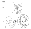
- FIG. 2 is a diagram illustrating a situation in which the user is using the mobile terminal 1 and an antenna selected by the mobile terminal 1.
- FIG. 2A shows a state where the user is talking with the mobile terminal 1 close to the ear. In this case, the mobile terminal 1 detects that the user is holding the mobile terminal 1 and is approaching the ear, and selects the antenna 122 far from the position of the ear to perform wireless communication.
- FIG. 2B is a diagram illustrating a state in which the user holds the mobile terminal 1 in a state of being separated from the ear. In this case, the mobile terminal 1 detects the state in which the user is holding the mobile terminal 1 using the side touch sensor 110 or the like. The portable terminal 1 estimates the operation area of the user's finger and selects an antenna whose feeding point is not covered by the user's hand based on the estimated result.
- FIG. 3 is a diagram for explaining the area of the main surface of the mobile terminal 1.
- FIG. 3A is a front view of the mobile terminal 1.
- FIG. 3B is a side view of the mobile terminal 1.
- the mobile terminal 1 divides the main surface into a plurality of areas.
- the region of the main surface is divided (classified) into a plurality of regions ⁇ , ⁇ , ⁇ as an example.
- Each of the regions ⁇ , ⁇ , and ⁇ is located in this order from the upper end side to the lower end side (operation key 105 side).
- the normal line from the feeding point P1 to the main surface intersects in the region ⁇ . That is, the feeding point P1 is located immediately below the region ⁇ in the plurality of regions ⁇ to ⁇ . Further, the normal line from the feeding point P2 to the main surface intersects in the region ⁇ . That is, the feeding point P2 is located immediately below the region ⁇ in the plurality of regions ⁇ , ⁇ , ⁇ .
- the movable range on the main surface of the thumb of the hand that the user is holding the mobile terminal 1 using the regions ⁇ , ⁇ , and ⁇ will be described later.
- the main surface is divided into three regions.
- the main surface is not limited to three.
- FIG. 4 is a diagram illustrating a state where the mobile terminal 1 is held sideways by the user.
- state A is a diagram showing a state where the user grips the right end side of mobile terminal 1 in the horizontal orientation (in the case of state A in FIG. 2, operation key 105 side) with the right hand.
- state B is a diagram showing a state in which the user grips the left end side of the mobile terminal 1 in the landscape orientation with the left hand.
- the surface (main surface, back surface, and side surface) of the mobile terminal 1 in the vicinity of the feeding point P2 of the antenna 122 is covered with hands.
- An antenna 121 that is not covered with a hand is selected as an antenna to be used for communication, and wireless communication is performed with a communication device using the antenna 121.
- the “surface in the vicinity of the feeding point” typically means the intersection of the principal surface normal passing through the feeding point and the principal surface, the intersection of the back normal passing through the feeding point and the back surface, And the intersection of the normal with the side surface passing through the feed point (typically, the side surface closest to the feed point) and the side surface.
- the “surface in the vicinity of the feeding point” can be a region in a predetermined range including the intersections (for example, a circular region having a radius of 5 mm or a rectangular region having a side of 5 mm).
- the mobile terminal 1 transitions from the state A to the state B, the surface of the antenna 121 near the feeding point P1 is covered with a hand. Therefore, the mobile terminal 1 selects the antenna 122 whose surface near the feeding point is not covered with a hand, and performs wireless communication with the communication device using the antenna 122.
- FIG. 5 is a diagram illustrating a state in which the user holds the mobile terminal 1 vertically.
- the state A is a view showing a state where the user holds the lower end side of the portable terminal 1 in the vertical orientation (the operation key 105 side in the case of the state A in FIG. 3) with the right hand. is there.
- State B is a diagram illustrating a state in which the user grips the upper end side of the mobile terminal 1 in the portrait orientation with the right hand.
- the mobile terminal 1 since the surface of the antenna 122 in the vicinity of the feeding point P ⁇ b> 2 is covered with a hand, the mobile terminal 1 performs wireless communication with the communication device using the antenna 121. That is, the mobile terminal 1 selects the antenna 121 whose surface near the feeding point is not covered with the hand.
- the mobile terminal 1 transitions from the state A to the state B, the surface of the antenna 121 near the feeding point P1 is covered with hands, so the mobile terminal 1 performs wireless communication with the communication device using the antenna 122. .
- the portable terminal 1 selects the antenna 122 whose casing surface near the feeding point is not covered with hands.
- the mobile terminal 1 selects at least one antenna used for communication with the communication device from the antennas 121 and 122 based on the grip state. Specifically, the mobile terminal 1 uses an antenna whose surface in the vicinity of the feeding point is not covered with a hand out of the two antennas 121 and 122 regardless of the attitude of the mobile terminal 1 (horizontal or vertical orientation). Use to communicate with communication equipment.
- the mobile terminal 1 can communicate with the communication device using the antenna having the better communication performance (communication quality).
- the mobile terminal 1 for realizing the antenna selection as described above will be described.
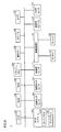
- FIG. 6 is a diagram illustrating a hardware configuration of the mobile terminal 1.
- the mobile terminal 1 includes a CPU 101 that executes a program, a ROM (Read Only Memory) 102, a RAM (Random Access Memory) 103, a flash memory 104, an operation key 105, a speaker 106, and the like.
- the touch screen 108 includes the display 1081 and the touch panel 1082 as described above.
- the components 101 to 112, 118, and 119 are connected to each other by a data bus.
- the antennas 121 and 122 are connected to the wireless communication IF 112.
- the antennas 121 and 122 and the wireless communication IF 112 are used, for example, for wireless communication with other mobile terminals, fixed telephones, and PCs (Personal Computers) via a base station.
- the ROM 102 is a nonvolatile semiconductor memory.
- the ROM 102 stores a boot program for the mobile terminal 1 in advance.
- the flash memory 104 is a nonvolatile semiconductor memory.
- the flash memory 104 may be configured as a NAND type as an example.
- the flash memory 104 stores various data such as an operating system of the mobile terminal 1, various programs for controlling the mobile terminal 1, data generated by the mobile terminal 1, and data acquired from an external device of the mobile terminal 1. To do.
- the processing in the portable terminal 1 is realized by each hardware and the CPU 101 executing each software and performing an operation in cooperation with each hardware.
- Such software may be stored in the flash memory 104 in advance.
- the software may be stored in a memory card or other storage medium (not shown) and distributed as a program product.
- the software may be provided as a program product that can be downloaded by an information provider connected to the so-called Internet.
- Such software is downloaded via the antennas 121 and 122 and the wireless communication IF 112 and then temporarily stored in the flash memory 104.
- the software is read from the flash memory 104 by the CPU 101 and further stored in the flash memory 104 in the form of an executable program.
- the CPU 101 executes the program.
- the VSWR sensor 118 is constituted by a detection circuit or the like, and transmits values of detection voltages of traveling waves and reflected waves to the CPU 101.
- the VSWR sensor 118 is for measuring the impedance change of the antenna 121 in the vicinity of the telephone speaker 119.
- Each component constituting the mobile terminal 1 shown in the figure is general. Therefore, it can be said that an essential part of the present invention is software stored in the flash memory 104 or other storage medium, or software that can be downloaded via a network.
- the recording medium is not limited to DVD (Digital Versatile Disc) -ROM, CD (Compact Disc) -ROM, FD (Floppy Disk), and hard disk, but also magnetic tape, cassette tape, optical disk, optical card, mask ROM, EPROM. (Erasable Programmable Read Only Memory), EEPROM (Electrically Erasable Programmable Read-Only Memory), a medium such as a semiconductor memory, such as a flash ROM, may be a medium that carries a fixed program.
- the recording medium is a non-temporary medium that can be read by the computer.
- the program here includes not only a program directly executable by the CPU but also a program in a source program format, a compressed program, an encrypted program, and the like.
- FIG. 7 is a diagram for explaining a functional configuration of the mobile terminal 1.
- the mobile terminal 1 includes a touch screen 108, a back touch sensor 109, a side touch sensor 110, an acceleration sensor 111, a VSWR sensor 118, a wireless communication IF 112, an antenna 121, and an antenna 122. And a control unit 200 and a storage unit 300.
- the wireless communication IF 112 includes an antenna switching processing unit 400.
- the control unit 200 includes a state detection unit 210, a movable region estimation unit 220, a communication control unit 230, and a display control unit 240.
- the state detection unit 210 includes a handle determination unit 211.
- the communication control unit 230 includes a selection unit 231.
- the storage unit 300 stores a data table D7.
- FIG. 8 is a diagram showing a schematic configuration of the data table D7.
- the posture (vertical, horizontal) of the mobile terminal 1, the handle of the user's mobile terminal 1 (the hand that is gripping), and the contact area (thumb) on the main surface ) are associated with each other.
- the movable range of the thumb on the main surface that is, the region on the main surface where the thumb can move in the gripping state
- the antenna to be selected are associated with each other.
- the contact area on the main surface is one of a plurality of areas ⁇ , ⁇ , ⁇ for convenience of explanation.
- the movable range of the thumb is one of a plurality of regions ⁇ , ⁇ , ⁇ , or a combination of two or more of these regions ⁇ , ⁇ , ⁇ .
- any one of the antenna 121, the antenna 122, and the currently used antenna is defined.
- the back touch sensor 109 detects the contact position of the hand on the back surface of the mobile terminal 1.
- the back touch sensor 109 sends the detected coordinate information of the contact position to the state detection unit 210 of the control unit 200.
- the side touch sensor 110 detects the contact position of the hand on the side surface of the mobile terminal 1.
- the side touch sensor 110 sends the coordinate information of the detected contact position to the state detection unit 210. Note that the coordinate information from each of the side surface touch sensors 110a to 110d is sent to the state detection unit 210 in a state of being distinguished for each side surface touch sensor.
- the acceleration sensor 111 detects the current orientation (portrait or landscape) of the mobile terminal 1 by gravity and detects the acceleration of the mobile terminal 1 by the user's action.
- the acceleration sensor 111 sends the measured acceleration information to the control unit 200. More specifically, the acceleration sensor 111 sends the measured acceleration information to the state detection unit 210 and the display control unit 240.
- the display control unit 240 has a screen rotation function and is detected based on the output from the acceleration sensor 111 that the posture of the mobile terminal 1 has changed from the first posture (for example, vertical) to the second posture (for example, horizontal).
- the display screen of the display 1081 is rotated 90 degrees.
- the state detection unit 210 detects the gripping state of the mobile terminal 1 by the user.
- the handle determination unit 211 of the state detection unit 210 determines whether the hand in contact with the mobile terminal 1 is the left hand or the right hand based on the contact position detected by the touch sensor.
- the state detection unit 210 detects a gripping state based on coordinate information from the touch panel 1082, coordinate information from the back touch sensor 109, coordinate information from the side touch sensor 110, and acceleration information from the acceleration sensor 111. . More specifically, the state detection unit 210 includes information on the detected contact position, posture information (portrait orientation or landscape orientation) of the mobile terminal 1, and whether the hand in contact is a left hand or a right hand. The gripping state is detected based on the hand information.
- the state detection unit 210 receives the output value of the VSWR sensor 118, calculates the VSWR value of the antenna 121, and is in a call state where the user holds the mobile terminal 1 and is close to the ear, or It is determined whether the portable terminal 1 is away from the position of the user's ear.
- the state detection unit 210 sends the detected gripping state to the movable region estimation unit 220. Specifically, the state detection unit 210 sends hand contact position information, posture information of the mobile terminal 1, and handle information as information indicating the gripping state to the movable region estimation unit 220.
- the movable area estimation unit 220 estimates the movable area on the surface of the thumb of the touching hand based on the information on the hand contact position, the posture information, and the handle information. Specifically, the movable region estimation unit 220 refers to the data table D7 and estimates the movable region on the main surface of the thumb. Specifically, the movable region estimation unit 220 estimates at least one region from among the regions ⁇ , ⁇ , ⁇ (see FIG. 8) as the movable region. In addition, the movable region estimation unit 220 sends hand contact position information, posture information, handle information, and information representing the estimated movable region to the communication control unit 230.
- the communication control unit 230 performs various processes necessary for wireless communication and controls communication using the wireless communication IF 112.
- the selection unit 231 of the communication control unit 230 selects at least one antenna used for communication with the communication device from the plurality of antennas 121 and 122 based on the detected gripping state.
- the selection unit 231 selects an antenna (antenna 122) that is far from the ear when the user is in a call-in state where the user holds the mobile terminal 1 and is close to the ear. Further, when the mobile terminal 1 is away from the position of the user's ear, the selection unit 231 has a hand on the surface of the mobile terminal 1 in the vicinity of the feeding point of the antenna among the plurality of antennas 121 and 122. Select an antenna that is not covered by. More specifically, the selection unit 231 has an antenna in which the surface in the vicinity of the feeding point of the antenna is not covered with a hand, and the estimated movable region is not in the vicinity of the feeding point among the plurality of antennas 121 and 122. Select. More specifically, the selection unit 231 selects an antenna to be used for communication with reference to the data table D7.
- the selection unit 231 refers to the data table D7, the posture is “vertical”, the handle is “left hand”, the contact area on the main surface is “ ⁇ ”, and the thumb movable area is “ ⁇ , ⁇ ”. Is selected (ie, antenna 122). The selection unit 231 notifies the antenna switching processing unit 400 of the selected antenna.
- the wireless communication IF 112 performs wireless communication with a communication device using the selected antenna. Specifically, the antenna switching processing unit 400 of the wireless communication IF 112 switches the antenna as necessary so that communication can be performed using the selected antenna. For example, when the antenna switching process unit 400 is notified that the antenna 122 has been selected from the selection unit 231 in a situation where the antenna 121 is being used, the antenna switching processing unit 400 performs a process of switching the antenna to be used from the antenna 121 to the antenna 122. .
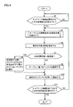
- FIG. 9 is a flowchart for explaining the flow of processing in the mobile terminal 1.
- CPU 101 of portable terminal 1 determines whether a processing request for starting connection to the network has been accepted in accordance with the execution of the program. If CPU 101 determines that a processing request has been accepted (YES in step S2), it performs the process of step S4. If not (NO in step S2), CPU 101 returns the process to step S2.
- step S4 the CPU 101 detects the gripping state of the mobile terminal 1 by the user.
- step S ⁇ b> 6 the CPU 101 uses the movable area estimation unit 220 to estimate the movable area on the main surface of the thumb.
- step S7 the CPU 101 measures the VSWR value, compares the VSWR value with the specified value, and determines whether or not the VSWR value is larger than the specified value.
- the CPU 101 determines that the user is in a call state holding the mobile terminal 1 and close to the ear, and performs the process of step S9. . Otherwise (NO in step S7), CPU 101 performs the process in step S8.
- step S8 the CPU 101 selects an antenna to be used for wireless communication from the antennas 121 and 122 based on the data table D7.
- step S9 the CPU 101 uses an antenna that is used for wireless communication as an antenna having a large distance from the call speaker 119, and the surface of the portable terminal 1 near the antenna feeding point is not covered by the user's hand. Select.
- the CPU 101 preferentially selects an antenna to be used for wireless communication with an antenna far from the call speaker 119.
- CPU 101 selects antenna 122 as an antenna used for wireless communication.
- step S10 the wireless communication IF 112 communicates with the communication device using the selected antenna.
- step S12 the CPU 101 determines whether or not a processing request for terminating the connection to the network has been received.
- CPU 101 determines that a processing request has been received (YES in step S12)
- the series of processing ends. Otherwise (NO in step S12), CPU 101 returns the process to step S4.
- FIG. 10 is a flowchart for explaining details of the process in step S4 in FIG. Referring to FIG. 10, in step S ⁇ b> 402, CPU 101 determines the attitude of portable terminal 1 based on the output from acceleration sensor 111.
- step S404 the CPU 101 acquires coordinate information representing the contact position of the hand from the back touch sensor 109 and the side touch sensor 110.
- step S406 the CPU 101 determines whether the handle holding the mobile terminal 1 is the left hand or the right hand.
- the portable terminal 1 is a portable portable terminal that wirelessly communicates with a communication device. Based on the output value of the VSWR sensor 118, the portable terminal 1 determines whether or not the speaker for call 119 and the user are approaching a certain distance or less. When the call speaker 119 and the user are close to each other within a certain distance (when the user is bringing the portable terminal 1 close to the ear), the portable terminal 1 gives priority to the antenna far from the ear, and the antenna for wireless communication Choose as. In addition, the mobile terminal 1 communicates with the plurality of antennas 121 and 122, the state detection unit 210 that detects the gripping state of the mobile terminal 1, and the plurality of antennas 121 and 122 based on the detected gripping state.
- a selection unit 231 that selects an antenna to be used for communication with a device, and a wireless communication IF 112 that wirelessly communicates with a communication device using the selected antenna. Therefore, the mobile terminal 1 responds to the gripping state by the user when the call speaker 119 and the user are not close to a certain distance or less (when the user holds the mobile terminal 1 at a position away from the ear). Thus, it is possible to select an antenna with good communication performance from among a plurality of antennas.
- Each of the plurality of antennas 121 and 122 is built in the mobile terminal 1.
- the selection unit 231 is based on the gripping state and is in the vicinity of the feeding point of the antenna among the plurality of antennas 121 and 122. An antenna whose surface is not covered with a hand is selected.
- the mobile terminal 1 selects an antenna whose surface near the feeding point is not covered with a hand, it is possible to select an antenna with good communication performance.
- the mobile terminal 1 further includes a touch screen 108 having a display surface on the main surface side, and touch sensors (109, 110) for detecting a contact position of a hand on the back and side surfaces of the mobile terminal 1.
- the state detection unit 210 detects a grip state based on the detected contact position. Thereby, the portable terminal 1 can detect a user's holding state.
- a display control unit 240 that rotates the display screen of the display 1081 of the touch screen 108 by 90 degrees. Since the state detection unit 210 detects the grip state based on the posture information representing either the first posture or the second posture, the mobile terminal 1 can detect the grip state in consideration of the posture information.
- the state detection unit 210 includes a handle determination unit 211 that determines whether the hand in contact with the portable terminal 1 is the left hand or the right hand based on the contact position.
- the mobile terminal 1 determines the movable region on the main surface of the thumb of the touching hand based on the contact position, the posture information, and the handle information indicating whether the touching hand is the left hand or the right hand.
- a movable region estimation unit 220 for estimation is further provided.
- the selection unit 231 selects an antenna whose estimated movable region is not near the feeding point from the plurality of antennas 121 and 122. Therefore, even if the user moves the thumb, the portable terminal 1 can select an antenna whose surface near the feeding point is not covered with a hand.
- the main surface of the mobile terminal 1 is divided into a plurality of regions ⁇ , ⁇ , ⁇ .
- the feeding point P1 of the antenna 121 among the plurality of antennas 121 and 122 is located immediately below the region ⁇ in the plurality of regions ⁇ , ⁇ , and ⁇ .
- the feeding point P2 of the antenna 122 of the plurality of antennas 121 and 122 is located immediately below the region ⁇ in the plurality of regions ⁇ , ⁇ , and ⁇ .
- the movable region estimation unit 220 estimates one or more regions of the plurality of regions ⁇ , ⁇ , and ⁇ as movable regions. Thereby, the portable terminal 1 can estimate the movable region of the thumb from a plurality of predetermined regions ⁇ , ⁇ , ⁇ .
- a storage unit 300 is further provided that stores a data table D7 representing the correspondence between the attitude of the mobile terminal 1, the handle, the regions ⁇ , ⁇ , ⁇ , and the antenna.
- the selection unit 231 selects at least one antenna used for communication with the communication device from the plurality of antennas 121 and 122 based on the data table D7. Thereby, the portable terminal 1 can select an antenna whose surface near the feeding point is not covered with a hand by storing the data table D7 in advance.
- the communication control method in the mobile terminal 1 is used for communication with a communication device from the plurality of antennas 121 and 122 based on the step of detecting the gripping state of the mobile terminal 1 and the detected gripping state. Selecting an antenna and wirelessly communicating with the communication device using the selected antenna. Thereby, the portable terminal 1 can select an antenna with good communication performance from among a plurality of antennas according to the gripping state by the user.
- a program for controlling the mobile terminal 1 is used for communication with a communication device from among the plurality of antennas 121 and 122 based on the step of detecting the gripping state of the mobile terminal 1 and the detected gripping state.
- the CPU 101 of the portable terminal 1 is caused to execute a step of selecting an antenna and a step of wirelessly communicating with a communication device using the selected antenna. Therefore, the mobile terminal 1 can select an antenna with good communication performance from among a plurality of antennas according to the gripping state by the user.
- the mobile terminal 1 includes the VSWR sensor 118, and the VSWR value based on the output of the VSWR sensor 118 and the output of the VSWR sensor 118 in a state where the telephone speaker 119 and the user are close to each other within a certain distance. It is determined whether or not the telephone speaker 119 and the user are approaching each other by comparing with a specified value based on. Thereby, a different antenna selection method can be realized depending on whether or not the user is close to the mobile terminal 1.
- FIG. 11 is a diagram for explaining the movable region of the thumb.
- the movable region of the thumb is divided into three regions ⁇ , ⁇ , and ⁇ , but the present invention is not limited to this.
- the movable area estimation unit 220 may be configured to estimate a more accurate movable area (for example, the area Q) according to the gripping state by the user.
- the movable region estimation unit 220 for example, a combination pattern of a plurality of coordinate information (coordinate values) representing a posture, a handle, and a contact position, a movable region of the thumb,
- the movable region may be estimated using a data table in which antennas are associated with each other.
- the movable region of the thumb may be estimated by calculation using a mathematical formula. Furthermore, it is good also as a structure which judges whether it belongs to any one of several patterns by calculation instead of matching previously the combination pattern of a coordinate in a data table.
- the portable terminal 1A selects an antenna whose surface near the feeding point is not covered with a hand from among antennas (antenna 122 and antenna 123) far from the speaker for call 119 as an antenna used for wireless communication.
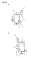
- FIG. 12 is a diagram showing antennas selected by the mobile terminal 1A when there are three antennas.
- state A in FIG. 12 when the user is making a call or the like with the mobile terminal 1 ⁇ / b> A close to the ear, the user holds the lower end side (the operation key 105 side) of the mobile terminal 1 ⁇ / b> A with the right hand.
- the portable terminal 1A is held vertically.
- the portable terminal 1A selects an antenna 123 that is an antenna far from the speaker for call 119 and whose surface near the feeding point is not covered with a hand, and communicates with a communication device using the antenna 123. I do.
- the mobile terminal 1A selects an antenna 122 that is an antenna far from the speaker for call 119 and whose surface in the vicinity of the feeding point is not covered with a hand, and communicates with a communication device using the antenna 122. I do.
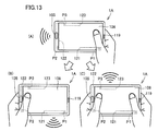
- FIG. 13 is a diagram illustrating a state where the user holds the mobile terminal 1A sideways.
- mobile terminal 1 ⁇ / b> A includes antennas 121, 122, and 123.
- the antenna 123 is fed by a feed line (not shown).
- the feeding point P3 is a connection point between the feeding line and the antenna 123. In the following description, it is assumed that the antenna performance decreases in the order of the antenna 122, the antenna 121, and the antenna 123.
- State A is a diagram showing a state in which the user grips the right end side of the mobile terminal 1A in the landscape orientation (the side on which the call speaker 119 is arranged in the case of State A in FIG. 13) with the right hand.
- State B is a diagram showing a state in which the user holds the left end side of the mobile terminal 1A in the landscape orientation with the left hand.
- State C is a diagram showing a state in which the user holds the left end side and the right end side of the mobile terminal 1A in the landscape orientation with the left hand and the right hand, respectively.
- the surface (main surface, back surface, and side surface) of the mobile terminal 1A in the vicinity of the feeding point P1 of the antenna 121 is covered with a hand.
- the antenna 122 has better performance than the antenna 123. Therefore, the mobile terminal 1 ⁇ / b> A performs wireless communication with the communication device using the antenna 122. That is, 1 A of portable terminals select the antenna 122 with the better performance among the antennas 122 and 123 whose surfaces near the feeding point are not covered with hands.
- the mobile terminal 1A selects the antenna 121 with the better performance among the antennas 121 and 123 whose surfaces near the feeding point are not covered with hands, and performs wireless communication with the communication device using the antenna 121. .
- the portable terminal 1A selects the remaining antenna 123 as an antenna whose surface near the feeding point is not covered with a hand, and performs wireless communication with the communication device using the antenna 123.
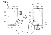
- FIG. 14 is a diagram illustrating a state in which the user holds the mobile terminal 1A vertically.
- state A represents a state in which the user grips the lower end side of portable terminal 1A in the vertical orientation (the operation key 105 side in the case of state A in FIG. 14) with the right hand.
- state B is a diagram showing a state in which the user grips the lower end side of portable terminal 1A in the vertically oriented posture with the left hand.
- the mobile terminal 1A selects the antenna 121 with the better performance among the antennas 121 and 123 whose surfaces near the feeding point are not covered with hands, and performs wireless communication with the communication device using the antenna 121. .
- the mobile terminal 1A selects the antenna 122 having the better performance from the antennas 121 and 122 whose casing surface near the feeding point is not covered with hands, and uses the antenna 122 to perform wireless communication with the communication device. To do.
- the mobile terminal 1A determines the antenna 121, based on the gripping state of the mobile terminal 1A by the user. At least one antenna used for communication with the communication device is selected from 122 and 123. Specifically, in the mobile terminal 1A, the surface of the three antennas 121, 122, and 123 in the vicinity of the feeding point is not covered with a hand regardless of the attitude of the mobile terminal 1 (horizontal orientation or vertical orientation). An antenna having the highest performance is used to communicate with a communication device.
- the above antenna selection process can be applied to a mobile terminal such as a smartphone that supports MIMO (multiple-input and multiple-output). That is, by combining two or more antennas from among a plurality of antennas, the bandwidth used for data transmission / reception can be expanded to apply the above antenna selection process to wireless communication.
- the selection unit selects at least two or more antennas used for communication with the communication device from the plurality of antennas.
- the movable region estimation unit 220 may estimate the movable areas of the index finger, the middle finger, the ring finger, and the little finger based on coordinate information, posture information, and the like from each sensor.
- the selection unit 231 may be configured to select an antenna in consideration of the movable region of the thumb and the movable region of fingers other than the thumb.
- a predetermined parallel movable distance is set from the current finger position, and the distance is set. It is good also as a movable area
- Embodiment 2 In the first embodiment, the configuration of the mobile terminal including the back touch sensor 109 and the side touch sensor 110 has been described. In Embodiment 2, a mobile terminal including a grip sensor instead of these sensors 109 and 110 will be described.
- the grip sensor is a sensor (tactile sensor) for detecting that the mobile terminal is gripped by the user.
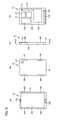
- FIG. 15 is a diagram for explaining a schematic configuration of the mobile terminal 1C according to the embodiment of the present invention.
- FIG. 15A is a front view of the mobile terminal 1C.
- FIG. 15B is a rear view of the mobile terminal 1C.
- FIG. 15C is a side view of the mobile terminal 1C.
- FIG. 15D is a cross-sectional view taken along line II-II in FIG.
- mobile terminal 1C includes a touch screen 108 and operation keys 105 on the main surface.
- the portable terminal 1C includes a camera 107 on the back surface.
- the mobile terminal 1C includes grip sensors 191 to 194 on the periphery (two side portions) of the housing. Specifically, two grip sensors are disposed on each of two side surfaces facing each other among the four side surfaces of the mobile terminal 1C. The two side surfaces are side surfaces in the longitudinal direction of the mobile terminal 1C.
- Each grip sensor 191 to 194 generates a predetermined signal upon detecting a hand contact.
- the signal is sent to the CPU 101.
- the user grips the portable terminal 1C with the right hand for example, when one finger is placed on one grip sensor 191, only one grip sensor 191 among the four grip sensors 191 to 194 generates the signal.
- the portable terminal 1C includes a plurality of antennas 121 and 122 and a plurality of electronic circuits 131 to 134 in the housing 10 as in the portable terminal 1.
- the portable terminal 1C selects one antenna from the antenna 121 and the antenna 122, and performs wireless communication with a communication device (other communication terminal, base station, etc.) not shown.
- the portable terminal 1C switches the antenna used for wireless communication between the antenna 121 and the antenna 122. A specific antenna selection method will be described later.
- the portable terminal 1C displays a display when the posture of the portable terminal 1C changes from a horizontal posture to a vertical posture, or when the posture changes from a vertical posture to a horizontal posture. It has a screen rotation function that rotates the screen by 90 degrees.
- the portable terminal 1C includes a sensor or the like. Based on the output result of the sensor, the user holds the portable terminal 1 and makes a call or the like close to the ear. Detect if you are going.
- the portable terminal 1C detects that the user holds the portable terminal 1C and is approaching the ear, the portable terminal 1C selects the antenna 122 far from the position of the ear and performs wireless communication.
- the mobile terminal 1C does not detect that the user's ear and the mobile terminal 1C are below a certain distance, the mobile terminal 1C performs wireless communication from among a plurality of antennas according to the state in which the user holds the mobile terminal 1C. Select the antenna to use.
- the mobile terminal 1 ⁇ / b> C has the same hardware configuration as the mobile terminal 1. Therefore, description of the hardware configuration of the mobile terminal 1C will not be repeated. However, in the following description, it is assumed that the antenna 122 has better performance than the antenna 121.
- FIG. 16 is a diagram illustrating a state where the user holds the mobile terminal 1C sideways.
- state A represents a state in which the user grips the right end side of portable terminal 1 ⁇ / b> C in the landscape orientation (the side opposite to operation key 105 in the case of state A in FIG. 16) with the right hand.
- FIG. State B is a diagram showing a state in which the user grips the left end side of the mobile terminal 1C in the landscape orientation with the left hand.
- the hand (specifically, the base of the thumb) contacts the grip sensor 193.
- the other grip sensors 191, 192, 194 are not touched by the hand. Therefore, only the grip sensor 193 generates a signal, and the remaining three grip sensors 191, 192, 194 do not generate a signal.
- the mobile terminal 1C since the mobile terminal 1C is in the horizontal position, the surface (main surface, back surface, and side surface) of the mobile terminal 1C in the vicinity of the feeding point P1 of the antenna 121 may be covered with a hand. Further, since the portable terminal 1C is in the horizontal position and only the grip sensor 193 generates a signal, the portable terminal 1C can determine that the user is holding the portable terminal 1C with the right hand. For this reason, the mobile terminal 1 ⁇ / b> C performs wireless communication with the communication device using the antenna 122. That is, 1 C of portable terminals select the antenna 122 which can judge that the surface of the vicinity of a feeding point is not covered with the hand. In other words, the mobile terminal 1 ⁇ / b> C selects the antenna 122 located farther from the grip sensor 193 among the antennas 121 and 122.
- the hand (specifically, the base of the thumb) contacts the grip sensor 194.
- the other grip sensors 191, 192 and 193 do not touch the hand. Therefore, only the grip sensor 194 generates a signal, and the remaining three grip sensors 191, 192, 193 do not generate a signal.
- the mobile terminal 1C since the mobile terminal 1C is in the horizontal position, the surface (main surface, back surface, and side surface) of the mobile terminal 1C in the vicinity of the feeding point P2 of the antenna 122 may be covered with hands. Further, since the mobile terminal 1C is in the horizontal position and only the grip sensor 194 generates a signal, the mobile terminal 1C can determine that the user is holding the mobile terminal 1C with the left hand. For this reason, the mobile terminal 1 ⁇ / b> C performs wireless communication with the communication device using the antenna 121. That is, 1 C of portable terminals select the antenna 121 which can be judged that the surface of the vicinity of a feeding point is not covered with the hand. In other words, the mobile terminal 1 ⁇ / b> C selects the antenna 121 located farther from the grip sensor 194 among the antennas 121 and 122.
- FIG. 17 is a diagram illustrating a state in which the user holds the mobile terminal 1C vertically.
- state A is a diagram showing a state in which the user grips the right end side of portable terminal 1 ⁇ / b> C in a vertically oriented posture with the right hand.
- state B is a diagram showing a state in which the user holds the left end side of the portable terminal 1C in the vertical orientation with the left hand.
- the hand (specifically, the base of the thumb) contacts the grip sensor 194.
- the other grip sensors 191, 192 and 193 do not touch the hand. Therefore, only the grip sensor 194 generates a signal, and the remaining three grip sensors 191, 192, 193 do not generate a signal.
- the mobile terminal 1C since the mobile terminal 1C is in the vertical position, the surface (main surface, back surface, and side surface) of the mobile terminal 1C in the vicinity of the feeding point P2 of the antenna 122 may be covered with hands. Further, since the mobile terminal 1C is in the vertical position and only the grip sensor 194 generates a signal, the mobile terminal 1C can determine that the user is holding the mobile terminal 1C with the right hand. For this reason, the mobile terminal 1 ⁇ / b> C performs wireless communication with the communication device using the antenna 121. That is, 1 C of portable terminals select the antenna 121 which can be judged that the surface of the vicinity of a feeding point is not covered with the hand. In other words, the mobile terminal 1 ⁇ / b> C selects the antenna 121 located farther from the grip sensor 194 among the antennas 121 and 122.
- the hand (specifically, the base of the thumb) contacts the grip sensor 192.
- the other grip sensors 191, 193, 194 are not touched by the hand. Therefore, only the grip sensor 192 generates a signal, and the remaining three grip sensors 191, 193, 194 do not generate a signal.
- the portable terminal 1C since the portable terminal 1C is in the vertical position and only the grip sensor 192 generates a signal, the portable terminal 1C can determine that the user is holding the portable terminal 1C with the left hand. Further, since the portable terminal 1C is in the vertical position, the portable terminal 1C can determine that the surface of the antenna 121 near the feeding point P1 and the surface of the antenna 122 near the feeding point P2 are not covered with hands. Furthermore, as described above, the performance of the antenna 122 is better than that of the antenna 121.
- the mobile terminal 1 ⁇ / b> C performs wireless communication with the communication device using the antenna 122. That is, 1 C of portable terminals select the antenna 122 with good antenna performance from the antennas 121 and 122 which can be judged that the surface in the vicinity of the feeding point is not covered with the hand.
- the mobile terminal 1C selects at least one antenna used for communication with the communication device from the antennas 121 and 122 based on the gripping state. Specifically, in the same manner as the mobile terminal 1, the mobile terminal 1 ⁇ / b> C has a surface near the feeding point of the two antennas 121 and 122, regardless of the orientation of the mobile terminal 1 ⁇ / b> C (lateral orientation or vertical orientation). Communicate with a communication device using an uncovered antenna.
- the mobile terminal 1C can communicate with the communication device using the antenna having the better communication performance (communication quality).
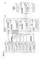
- FIG. 18 is a diagram for explaining the functional configuration of the mobile terminal 1C.
- the mobile terminal 1C includes a touch screen 108, an acceleration sensor 111, a wireless communication IF 112, a VSWR sensor 118, an antenna 121, an antenna 122, grip sensors 191 to 194, and a control unit 200A. And a storage unit 300.
- the portable terminal 1 according to the first embodiment is different from the portable terminal 1 of the first embodiment in that grip sensors 191 to 194 are provided instead of the back touch sensor 109 and the side touch sensor 110 and a control unit 200A is provided instead of the control unit 200. Is different.
- Control unit 200A includes a state detection unit 210A, a communication control unit 230, and a display control unit 240.
- 200 A of control parts differ from the portable terminal 1 of Embodiment 1 in the point which does not include the movable region estimation part 220, and the point provided with the state detection part 210A instead of the state detection part 210.
- FIG. 1 A of control parts differ from the portable terminal 1 of Embodiment 1 in the point which does not include the movable region estimation part 220, and the point provided with the state detection part 210A instead of the state detection part 210.
- the state detection unit 210A detects the gripping state of the mobile terminal 1C by the user based on the output signals from the grip sensors 191 to 194.
- FIG. 19 is a flowchart for explaining the flow of processing in the mobile terminal 1C.
- portable terminal 1 ⁇ / b> C (specifically CPU 101) detects a gripping state of portable terminal 1 ⁇ / b> C by the user in step S ⁇ b> 4 ⁇ / b> A after a positive determination is made in step S ⁇ b> 2.
- the portable terminal 1C advances the process to step S7 after step S4A. Since each process in steps S2, 7, 8, 9, 10, and 12 has been described based on FIG. 9, it will not be repeated here.
- FIG. 20 is a flowchart for explaining details of the process of step S4A in FIG.
- CPU 101 determines the attitude of portable terminal 1 ⁇ / b> C based on the output from acceleration sensor 111.
- step S404A the CPU 101 determines one or more grip sensors with which the user's hand is in contact based on output signals from the grip sensors 191 to 194.
- step S406 the CPU 101 determines whether the hand holding the mobile terminal 1 is the left hand or the right hand based on the attitude of the mobile terminal 1C and information on the grip sensor with which the user is in contact. .
Landscapes
- Engineering & Computer Science (AREA)
- Computer Networks & Wireless Communication (AREA)
- Signal Processing (AREA)
- Telephone Function (AREA)
Abstract
複数のアンテナを備える携帯端末において、無線通信に適したアンテナを選択するための技術を提供する。携帯端末(1)は、複数のアンテナ(121,122)と、通話用スピーカ(119)とを備える。携帯端末(1)は、通話用スピーカ(119)の近傍に設けられ、通話用スピーカ(119)とユーザの頭部との距離に応じた信号を出力するセンサを備える。携帯端末(1)は、センサから出力される信号に応じて携帯端末(1)とユーザの頭部とが一定距離以内にあることを検出した場合に、複数のアンテナ(121,122)のうち、通話用スピーカ(119)から遠い位置にあるアンテナで給電点の近傍の携帯端末の表面がユーザの手で覆われていないアンテナ(122)を、無線通信に使用するアンテナとして選択する。携帯端末(1)は、携帯端末(1)とユーザの頭部とが一定距離以内にないと検出した場合に、ユーザによる携帯端末(1)の把持状態に応じて、無線通信に使用するアンテナを選択する。
Description
本発明は、複数のアンテナを備えて無線通信を行う携帯端末に関し、無線通信に使用するアンテナを切り替えるための技術に関する。
複数のアンテナを用いて他の装置と無線通信する携帯端末が広く普及している。このような携帯端末においては、ユーザがアンテナに近い表面を手で覆ってしまうと、通信性能が劣化してしまう。これら携帯端末は、複数のアンテナのうちから使用するアンテナを切り替えている。
複数のアンテナを備える携帯端末に関する技術は様々なものがある。例えば、特許文献1は、携帯無線端末において、ダイバーシティ効果を最適化し、人体によるアンテナ特性への悪影響とSAR(Synthetic Aperture Radar)値とを低減する技術を開示している。
アンテナの給電点の周囲が、ユーザの手などによって覆われている場合、アンテナの特性が悪化する。特許文献1は、「端末が開かれた状態(開状態)か、或いは折り重ねられた状態(閉状態)の何れの使用状態(開閉状態)であるのか、また、携帯電話端末が通話中のいわゆるトークポジション状態か、或いは例えばデータ通信中のように利用者の手に持たれているハンドホールド状態の何れの使用状態であるのか等により、第1,第2,第3アンテナ21,22,23の三つのアンテナのうちの二つのアンテナを選択して決定し、さらにその一方を送受信アンテナ、他方を受信専用アンテナに決定する。」(特許文献1の段落0019)ことを記載している。しかし、ユーザが携帯無線端末を把持している場合に、アンテナの給電点の周囲がユーザの手によって覆われている可能性もある。
本発明は、携帯端末が複数のアンテナを備える場合に、これら無線通信に使用するアンテナを適切に選択するための技術を提供することを目的とする。
一実施の形態に従うと、通信機器と無線通信する携帯端末が提供される。携帯端末は、複数のアンテナと、通話用のスピーカと、スピーカの近傍に設けられ、スピーカとユーザの頭部との距離に応じた信号を出力するセンサと、無線通信に使用するアンテナの切り替え動作を制御する制御手段と、制御手段の制御によって切り替えられたアンテナを用いて、通信機器と無線通信する通信インターフェイスとを備える。制御手段は、携帯端末とユーザとの接触位置に基づいて、ユーザによる携帯端末の把持状態を検出する検出部と、センサから出力される信号に応じて、スピーカとユーザの頭部とが一定距離以下に接近しているか否かを判定する判定部と、判定部により、スピーカとユーザの頭部とが接近していないと判定される場合に、検出された把持状態に基づいて、複数のアンテナのうち少なくとも1つのアンテナを選択し、かつ、判定部により、スピーカとユーザの頭部とが接近していると判定される場合に、複数のアンテナのうち、ユーザの頭部からの距離の大きさに基づき少なくとも1つのアンテナを選択する選択部とを含む。
一実施の形態に従う携帯端末によれば、複数のアンテナのうちから通信性能の良いアンテナを選択し、また、人体に対する電波の放射量を低減することが可能となる。
以下、図面を参照しつつ、本発明の各実施の形態に係る携帯端末について説明する。以下の説明では、同一の部品には同一の符号を付してある。それらの名称および機能も同じである。したがって、それらについての詳細な説明は繰り返さない。なお、無線通信が可能な携帯端末としては、たとえば、スマートフォン、タブレット端末が挙げられるが、特にこれらに限定されるものではない。
<実施の形態1>
<A.携帯端末1の概略構成>
図1は、本発明の実施の形態に係る携帯端末1の概略構成を説明するための図である。図1(A)は、携帯端末1の正面図である。図1(B)は、携帯端末1の背面図である。図1(C)は、携帯端末1の側面図である。図1(D)は、図1(C)におけるI-I線矢視断面図である。
<A.携帯端末1の概略構成>
図1は、本発明の実施の形態に係る携帯端末1の概略構成を説明するための図である。図1(A)は、携帯端末1の正面図である。図1(B)は、携帯端末1の背面図である。図1(C)は、携帯端末1の側面図である。図1(D)は、図1(C)におけるI-I線矢視断面図である。
図1(A),(C)を参照して、携帯端末1は、主面に、タッチスクリーン108と、操作キー105とを備えている。タッチスクリーン108は、ディスプレイとタッチパネルとを含む。また、携帯端末1は、各側面に、側面タッチセンサ110a,110b,110c,110dを備えている。携帯端末1は、各側面タッチセンサ110a,110b,110c,110dを、筐体10の表面に備える。各側面タッチセンサ110a,110b,110c,110dは、たとえば、静電容量方式のセンサで構成することができる。また、静電容量方式のタッチセンサを筐体10の側面に設ける代わりに、タッチパネルを、ホバー対応のものとすることもできる。携帯端末1が狭ベゼルの端末であれば、筐体の側面にも電界が回り込んでくるため、携帯端末1は、ホバー対応のタッチパネルを設けることにより、筐体側面の指や手の接触位置を検出することができる。
以下では、4つの側面タッチセンサ110a,110b,110c,110dを、「側面タッチセンサ110」と総称することもある。側面タッチセンサ110は、4つの側面タッチセンサ110a,110b,110c,110dを含み得る。
図1(B)を参照して、携帯端末1は、背面に、カメラ107と、背面タッチセンサ109とを備えている。背面タッチセンサ109は、側面タッチセンサ110と同様、たとえば、静電容量方式のセンサで構成することができる。
図1(D)を参照して、携帯端末1は、筐体10内に、複数のアンテナ121,122と、複数の電子回路131,132,133,134とを備える。各電子回路131~134は、図示しない基板上に配置される。
アンテナ121は、図示しない給電線により給電される。給電点P1は、当該給電線とアンテナ121との接続点である。また、アンテナ122は、図示しない給電線により給電される。給電点P2は、当該給電線とアンテナ122との接続点である。
携帯端末1は、アンテナ121およびアンテナ122から1つのアンテナを選択し、図示しない通信機器(他の通信端末、基地局等)との間で無線通信を行なう。携帯端末1は、無線通信に利用するアンテナをアンテナ121とアンテナ122との間で切り替える。アンテナの具体的な選択の手法については、後述する。
また、携帯端末1は、携帯端末1の姿勢が横向き(横長)の姿勢から縦向き(縦長)の姿勢に変化した場合、または、当該姿勢が縦向きの姿勢から横向きの姿勢に変化した場合、ディスプレイの表示画面を90度回転させる画面回転機能を有する。
また、携帯端末1は、距離測定用のセンサ等を備えて、ユーザが携帯端末1を保持して頭部、特に耳に近づけて通話等を行っているか否かを検出する。本実施形態では、携帯端末1は、距離測定用のセンサとして、VSWR(Voltage Standing Wave Ratio)センサを、通話用スピーカ119の近傍に配置している。VSWRセンサは、検波回路等により構成され、進行波と反射波の検波電圧の値を、携帯端末1のプロセッサへ送信する。CPUは、進行波と反射波の検波電圧の比に基づいて反射係数を算出し、この反射係数に基づいてVSWR値を測定する。このVSWR値は、通話用スピーカ119に近いアンテナ(アンテナ121)のインピーダンス変化に相当する値である。なお、距離測定用のセンサとしては、上記VSWRセンサには限定されず、携帯端末に実装されることが多い近接センサや照度センサ等の他のセンサを用いてもよい。これにより、携帯端末1は、新たなセンサを追加することなく、従来より搭載されている構成物を用いて、以下の各実施形態に示す動作を行うことができる。
携帯端末1は、予め定められている規定値を記憶している。携帯端末1は、VSWR値と規定値とを比較することで、ユーザが携帯端末1を保持して耳に近づけている通話中の状態であるか、または携帯端末1がユーザの耳の位置から離れているかを判断する。すなわち、携帯端末1は、VSWR値が規定値よりも大きい場合に、ユーザが携帯端末1を保持して耳に近づけている通話中の状態であると判定し、VSWR値が規定値よりも小さい場合に、携帯端末1がユーザの耳の位置から離れている状態であると判定する。
図2は、ユーザが携帯端末1を使用している状況、および、携帯端末1によって選択されるアンテナを示す図である。図2(A)は、ユーザが携帯端末1を耳に近づけて通話している状態を示す。この場合、携帯端末1は、ユーザが携帯端末1を保持して耳に近づけていることを検出し、耳の位置から遠いアンテナ122を選択して無線通信を行う。図2(B)は、ユーザが携帯端末1を耳から離れた状態で保持している状態を示す図である。この場合、携帯端末1は、ユーザが携帯端末1を把持している状態を、側面タッチセンサ110等によって検出する。携帯端末1は、ユーザの指の操作領域を推定し、推定された結果に基づいて、給電点がユーザの手によって覆われていないアンテナを選択する。
図3は、携帯端末1の主面の領域を説明するための図である。図3(A)は、携帯端末1の正面図である。図3(B)は、携帯端末1の側面図である。
ユーザの指の操作領域を推定するため、携帯端末1は、主面を複数の領域に分けている。図3を参照して、主面の領域は、一例として、複数の領域α,β,γに分割(分類)される。領域α,β,γの各々は、この順に、上端側から下端側(操作キー105側)に位置している。
給電点P1から主面への法線は、領域αで交わる。つまり、給電点P1は、複数の領域α~δにおける領域αの直下に位置する。また、給電点P2から主面への法線は、領域γで交わる。つまり、給電点P2は、複数の領域α、β、γにおける領域γの直下に位置する。
領域α,β,γを用いた、ユーザが携帯端末1を把持している手の親指の、主面における可動範囲については後述する。なお、上記においては、主面を3つの領域に分けているが、複数であればよく、3つに限定されるものではない。
<B.アンテナの選択(切替)の概要>
図4は、携帯端末1がユーザによって横向きに把持された状態を示す図である。図4を参照して、状態Aは、横向きの姿勢の携帯端末1の右端側(図2の状態Aの場合には操作キー105側)を、ユーザが右手で把持した状態を示す図である。状態Bは、横向きの姿勢の携帯端末1の左端側を、ユーザが左手で把持した状態を示す図である。
図4は、携帯端末1がユーザによって横向きに把持された状態を示す図である。図4を参照して、状態Aは、横向きの姿勢の携帯端末1の右端側(図2の状態Aの場合には操作キー105側)を、ユーザが右手で把持した状態を示す図である。状態Bは、横向きの姿勢の携帯端末1の左端側を、ユーザが左手で把持した状態を示す図である。
状態Aにおいては、アンテナ122の給電点P2の近傍の携帯端末1の表面(主面,背面,および側面)が手で覆わることになるため、携帯端末1は、給電点の近傍の表面が手で覆われていないアンテナ121を、通信に使用するアンテナとして選択し、アンテナ121を用いて通信機器と無線通信を行なう。
なお、「給電点の近傍の表面」とは、典型的には、給電点を通る主面の法線と当該主面との交点、給電点を通る背面の法線と当該背面との交点、および給電点を通る側面(典型的には、給電点に最も近い側面)の法線と当該側面との交点である。あるいは、「給電点の近傍の表面」は、上記各交点を含む予め定められた範囲の領域(たとえば、半径5mmの円領域、あるいは一辺が5mmの矩形領域)とすることができる。
携帯端末1が状態Aから状態Bに遷移すると、アンテナ121の給電点P1の近傍の表面が手で覆われることになる。そのため、携帯端末1は、給電点の近傍の表面が手で覆われていないアンテナ122を選択し、アンテナ122を用いて通信機器と無線通信を行なう。
図5は、ユーザが携帯端末1を縦向きに把持した状態を示す図である。図5を参照して、状態Aは、縦向きの姿勢の携帯端末1の下端側(図3の状態Aの場合には操作キー105側)を、ユーザが右手で把持した状態を示す図である。状態Bは、縦向きの姿勢の携帯端末1の上端側を、ユーザが右手で把持した状態を示す図である。
図5の状態Aにおいては、アンテナ122の給電点P2の近傍の表面が手で覆われることになるため、携帯端末1は、アンテナ121を用いて通信機器と無線通信を行なう。つまり、携帯端末1は、給電点の近傍の表面が手で覆われていないアンテナ121を選択する。
携帯端末1が状態Aから状態Bに遷移すると、アンテナ121の給電点P1の近傍の表面が手で覆われることになるため、携帯端末1は、アンテナ122を用いて通信機器と無線通信を行なう。携帯端末1は、給電点の近傍の筐体表面が手で覆われていないアンテナ122を選択する。
以上のように、携帯端末1は、把持状態に基づいて、アンテナ121,122のうちから、通信機器との通信に用いる少なくとも1つのアンテナを選択する。具体的には、携帯端末1は、携帯端末1の姿勢(横向きまたは縦向きの姿勢)にかかわらず、2つのアンテナ121,122のうち給電点の近傍の表面が手で覆われていないアンテナを用いて、通信機器と通信する。
これにより、携帯端末1は、通信性能(通信品質)のよい方のアンテナを用いて、通信機器と通信することが可能となる。以下、上記のようなアンテナの選択を実現するための携帯端末1の具体的な構成について説明する。
<C.ハードウェア構成>
図6は、携帯端末1のハードウェア構成を表した図である。図6を参照して、携帯端末1は、プログラムを実行するCPU101と、ROM(Read Only Memory)102と、RAM(Random Access Memory)103と、フラッシュメモリ104と、操作キー105と、スピーカ106と、カメラ107と、タッチスクリーン108と、背面タッチセンサ109と、側面タッチセンサ110と、加速度センサ111と、無線通信IF(Interface)112と、VSWRセンサ118と、通話用スピーカ119と、アンテナ121と、アンテナ122とを少なくとも含んで構成されている。タッチスクリーン108は、上述したように、ディスプレイ1081と、タッチパネル1082とを含む。各構成要素101~112、118、119は、相互にデータバスによって接続されている。
図6は、携帯端末1のハードウェア構成を表した図である。図6を参照して、携帯端末1は、プログラムを実行するCPU101と、ROM(Read Only Memory)102と、RAM(Random Access Memory)103と、フラッシュメモリ104と、操作キー105と、スピーカ106と、カメラ107と、タッチスクリーン108と、背面タッチセンサ109と、側面タッチセンサ110と、加速度センサ111と、無線通信IF(Interface)112と、VSWRセンサ118と、通話用スピーカ119と、アンテナ121と、アンテナ122とを少なくとも含んで構成されている。タッチスクリーン108は、上述したように、ディスプレイ1081と、タッチパネル1082とを含む。各構成要素101~112、118、119は、相互にデータバスによって接続されている。
アンテナ121,122は、無線通信IF112に接続されている。アンテナ121,122、および無線通信IF112は、たとえば、基地局を介した、他の移動体端末、固定電話、およびPC(Personal Computer)との間における無線通信に用いられる。
ROM102は、不揮発性の半導体メモリである。ROM102は、携帯端末1のブートプログラムを予め格納している。
フラッシュメモリ104は、不揮発性の半導体メモリである。フラッシュメモリ104は、一例としてNAND型で構成してもよい。フラッシュメモリ104は、携帯端末1のオペレーティングシステム、携帯端末1を制御するための各種のプログラム、並びに、携帯端末1が生成したデータ、携帯端末1の外部装置から取得したデータ等の各種データを格納する。
携帯端末1における処理は、各ハードウェアおよびCPU101が各ソフトウェアを実行し、各ハードウェアと協働した動作を行うことによって実現される。このようなソフトウェアは、フラッシュメモリ104に予め記憶されている場合がある。また、ソフトウェアは、図示しないメモリカードその他の記憶媒体に格納されて、プログラムプロダクトとして流通している場合もある。あるいは、ソフトウェアは、いわゆるインターネットに接続されている情報提供事業者によってダウンロード可能なプログラムプロダクトとして提供される場合もある。このようなソフトウェアは、アンテナ121,122、および無線通信IF112を介してダウンロードされた後、フラッシュメモリ104に一旦格納される。そのソフトウェアは、CPU101によってフラッシュメモリ104から読み出され、さらにフラッシュメモリ104に実行可能なプログラムの形式で格納される。CPU101は、そのプログラムを実行する。
VSWRセンサ118は、検波回路等によって構成され、進行波と反射波の検波電圧の値をCPU101へ送信する。実施の形態1では、VSWRセンサ118は、通話用スピーカ119の近傍にあるアンテナ121のインピーダンス変化を計測するためのものである。
同図に示される携帯端末1を構成する各構成要素は、一般的なものである。したがって、本発明の本質的な部分は、フラッシュメモリ104その他の記憶媒体に格納されたソフトウェア、あるいはネットワークを介してダウンロード可能なソフトウェアであるともいえる。
なお、記録媒体としては、DVD(Digital Versatile Disc)-ROM、CD(Compact Disc)-ROM、FD(Floppy Disk)、ハードディスクに限られず、磁気テープ、カセットテープ、光ディスク、光カード、マスクROM、EPROM(Erasable Programmable Read Only Memory)、EEPROM(Electrically Erasable Programmable Read-Only Memory)、フラッシュROMなどの半導体メモリ等の固定的にプログラムを担持する媒体でもよい。また、記録媒体は、当該プログラム等をコンピュータが読取可能な一時的でない媒体である。また、ここでいうプログラムとは、CPUにより直接実行可能なプログラムだけでなく、ソースプログラム形式のプログラム、圧縮処理されたプログラム、暗号化されたプログラム等を含む。
<D.機能的構成およびデータ>
図7は、携帯端末1の機能的構成を説明するための図である。図7を参照して、携帯端末1は、タッチスクリーン108と、背面タッチセンサ109と、側面タッチセンサ110と、加速度センサ111と、VSWRセンサ118と、無線通信IF112と、アンテナ121と、アンテナ122と、制御部200と、記憶部300とを備えている。
図7は、携帯端末1の機能的構成を説明するための図である。図7を参照して、携帯端末1は、タッチスクリーン108と、背面タッチセンサ109と、側面タッチセンサ110と、加速度センサ111と、VSWRセンサ118と、無線通信IF112と、アンテナ121と、アンテナ122と、制御部200と、記憶部300とを備えている。
無線通信IF112は、アンテナ切替処理部400を含んでいる。制御部200は、状態検出部210と、可動領域推定部220と、通信制御部230と、表示制御部240とを含む。状態検出部210は、持手判断部211を有する。通信制御部230は、選択部231を有する。記憶部300は、データテーブルD7を格納している。
制御部200に含まれる各機能ブロックおよび無線通信IFに含まれる機能ブロック等の説明を行なう前に、データテーブルD7の概要について説明する。
図8は、データテーブルD7の概略構成を表した図である。図8を参照して、データテーブルD7では、携帯端末1の姿勢(縦,横)と、ユーザの携帯端末1の持ち手(把持している方の手)と、主面における接触領域(親指の接触領域)と、主面における親指の可動範囲(つまり、把持状態で親指が動くことが可能な主面上の領域)と、選択するアンテナとが対応付けられている。
主面における接触領域は、説明の便宜上、複数の領域α,β,γのいずれかとする。また、親指の可動範囲は、複数の領域α,β,γのいずれか、またはこれら領域α,β,γのうちの2つ以上の組み合わせとする。選択するアンテナとしては、アンテナ121、アンテナ122、現在利用しているアンテナ(アンテナ121またはアンテナ122)の3つのうちのいずれかが規定されている。
再び、図7を参照して、携帯端末1における処理を説明する。背面タッチセンサ109は、携帯端末1の背面における手の接触位置を検知する。背面タッチセンサ109は、検知した接触位置の座標情報を制御部200の状態検出部210に送る。
側面タッチセンサ110は、携帯端末1の側面における手の接触位置を検知する。側面タッチセンサ110は、検知した接触位置の座標情報を状態検出部210に送る。なお、各側面タッチセンサ110a~110dからの座標情報は、側面タッチセンサ毎に区別された状態で状態検出部210に送られる。
加速度センサ111は、携帯端末1の現在の向き(縦向きか横向きか)を重力により検知するとともに、ユーザの動作による携帯端末1の加速度を検出する。加速度センサ111は、測定した加速度の情報を制御部200に送る。より詳しくは、加速度センサ111は、測定した加速度の情報を、状態検出部210と表示制御部240とに送る。
表示制御部240は、画面回転機能を有し、加速度センサ111からの出力に基づき携帯端末1の姿勢が第1の姿勢(たとえば縦)から第2の姿勢(たとえば横)に変化したと検知された場合に、ディスプレイ1081の表示画面を90度回転させる。
状態検出部210は、ユーザによる携帯端末1の把持状態を検出する。状態検出部210の持手判断部211は、タッチセンサが検知する接触位置に基づき、携帯端末1に接触している手が左手および右手のいずれであるかを判断する。
ユーザによる携帯端末1の把持状態の検出について、詳しく説明すれば、以下のとおりである。状態検出部210は、タッチパネル1082からの座標情報と、背面タッチセンサ109からの座標情報と、側面タッチセンサ110からの座標情報と、加速度センサ111からの加速度情報とに基づき、把持状態を検出する。より詳しくは、状態検出部210は、検知された接触位置の情報と、携帯端末1の姿勢情報(縦向きまたは横向き)と、接触している手が左手および右手のいずれであるかを表す持手情報とに基づき、把持状態を検出する。また、状態検出部210は、VSWRセンサ118の出力値を受け付けて、アンテナ121のVSWR値を算出し、ユーザが携帯端末1を保持して耳に近づけている通話中の状態であるか、または携帯端末1がユーザの耳の位置から離れているかを判断する。
状態検出部210は、検出した把持状態を、可動領域推定部220に送る。具体的には、状態検出部210は、把持状態を表す情報として、手の接触位置の情報と、携帯端末1の姿勢情報と、持手情報とを、可動領域推定部220に送る。
可動領域推定部220は、手の接触位置の情報と、姿勢情報と、持手情報とに基づき、接触している手の親指の表面における可動領域を推定する。具体的には、可動領域推定部220は、データテーブルD7を参照して、親指の主面における可動領域を推定する。具体的には、可動領域推定部220は、可動領域として、領域α,β,γ(図8参照)のうちから少なくとも1つの領域を推定する。また、可動領域推定部220は、手の接触位置の情報と、姿勢情報と、持手情報と、推定した可動領域を表す情報とを、通信制御部230に送る。
通信制御部230は、無線通信に必要な各種の処理を行ない、無線通信IF112を用いた通信を制御する。
通信制御部230の選択部231は、上記検出された把持状態に基づいて、複数のアンテナ121,122のうちから、通信機器との通信に用いる少なくとも1つのアンテナを選択する。
具体的には、選択部231は、ユーザが携帯端末1を保持して耳に近づけている通話中の状態である場合は、耳から離れているアンテナ(アンテナ122)を選択する。また、選択部231は、携帯端末1がユーザの耳の位置から離れている状態である場合は、複数のアンテナ121,122のうちから、アンテナの給電点の近傍の携帯端末1の表面が手で覆われていないアンテナを選択する。より詳しくは、選択部231は、複数のアンテナ121,122のうちから、アンテナの給電点の近傍の表面が手で覆われておらず、かつ推定された可動領域が給電点の近傍とならないアンテナを選択する。さらに詳しくは、選択部231は、データテーブルD7を参照して、通信に利用するアンテナを選択する。
選択部231における選択処理の一例を挙げて説明すれば、以下のとおりである。携帯端末1の姿勢が縦向き、持ち手が左、主面における接触領域がβとなるように、ユーザが携帯端末1を把持していたとする。また、当該把持状態に基づき推定される親指の可動領域が、領域α,βであったとする。この場合、選択部231は、データテーブルD7を参照して、姿勢が「縦」,持ち手が「左手」、主面における接触領域が「β」,および親指の可動領域が「α,β」に対応付けられたアンテナ(つまり、アンテナ122)を選択する。選択部231は、選択したアンテナをアンテナ切替処理部400に通知する。
無線通信IF112は、選択されたアンテナを用いて、通信機器と無線通信する。詳しくは、無線通信IF112のアンテナ切替処理部400が、選択されたアンテナを用いて通信が行えるように、必要に応じてアンテナを切り替える。たとえば、アンテナ切替処理部400は、アンテナ121が使用されている状況において、選択部231からアンテナ122が選択されたことを通知されると、利用するアンテナをアンテナ121からアンテナ122に切り換える処理を行なう。
<E.制御構造>
図9は、携帯端末1における処理の流れを説明するためのフローチャートである。図9を参照して、ステップS2において、携帯端末1のCPU101は、プログラムの実行に応じて、ネットワークへの接続を開始するための処理要求を受付けたか否かを判断する。CPU101は、処理要求を受付けたと判断した場合(ステップS2においてYES)、ステップS4の処理を行い、そうでない場合(ステップS2においてNO)は、処理をステップS2に戻す。
図9は、携帯端末1における処理の流れを説明するためのフローチャートである。図9を参照して、ステップS2において、携帯端末1のCPU101は、プログラムの実行に応じて、ネットワークへの接続を開始するための処理要求を受付けたか否かを判断する。CPU101は、処理要求を受付けたと判断した場合(ステップS2においてYES)、ステップS4の処理を行い、そうでない場合(ステップS2においてNO)は、処理をステップS2に戻す。
ステップS4において、CPU101は、ユーザによる携帯端末1の把持状態を検出する。ステップS6において、CPU101は、可動領域推定部220により、親指の主面における可動領域を推定する。ステップS7において、CPU101は、VSWR値を測定し、VSWR値と規定値とを比較して、VSWR値が規定値よりも大きいか否かを判断する。VSWR値が規定値よりも大きい場合(ステップS7においてYES)に、CPU101は、ユーザが携帯端末1を保持して耳に近づけている通話中の状態であると判断し、ステップS9の処理を行う。そうでない場合(ステップS7においてNO)、CPU101は、ステップS8の処理を行う。
ステップS8において、CPU101は、無線通信に利用するアンテナを、データテーブルD7に基づいて、アンテナ121,122のうちから選択する。
ステップS9において、CPU101は、無線通信に利用するアンテナを、通話用スピーカ119から距離の大きいアンテナであって、アンテナの給電点の近傍の携帯端末1の表面がユーザの手で覆われていないアンテナを選択する。CPU101は、無線通信に利用するアンテナを、通話用スピーカ119から遠いアンテナを優先して選択する。実施の形態1では、CPU101は、無線通信に利用するアンテナとして、アンテナ122を選択する。
ステップS10において、無線通信IF112は、選択されたアンテナを用いて、通信機器と通信する。
ステップS12において、CPU101は、ネットワークへの接続を終了させるための処理要求を受付けたか否かを判断する。CPU101は、処理要求を受付けたと判断した場合(ステップS12においてYES)、一連の処理を終了する。そうでない場合(ステップS12においてNO)、CPU101は、処理をステップS4に戻す。
図10は、図9におけるステップS4の処理の詳細を説明するためのフローチャートである。図10を参照して、ステップS402において、CPU101は、加速度センサ111からの出力に基づき、携帯端末1の姿勢を判断する。
ステップS404において、CPU101は、背面タッチセンサ109および側面タッチセンサ110から、手の接触位置を表す座標情報を取得する。
ステップS406において、CPU101は、携帯端末1を把持している持ち手が、左手であるか右手であるかを判断する。
<F.まとめ>
(1)携帯端末1は、通信機器と無線通信する携帯型の携帯端末である。携帯端末1は、VSWRセンサ118の出力値に基づき、通話用スピーカ119とユーザとが一定距離以下に接近しているか否かを判定する。通話用スピーカ119とユーザとが一定距離以下に接近している場合(ユーザが携帯端末1を耳に近づけている場合)、携帯端末1は、耳から遠いアンテナを優先して無線通信用のアンテナとして選択する。また、携帯端末1は、複数のアンテナ121,122と、携帯端末1の把持状態を検出する状態検出部210と、検出された把持状態に基づいて、複数のアンテナ121,122のうちから、通信機器との通信に用いるアンテナを選択する選択部231と、選択されたアンテナを用いて、通信機器と無線通信する無線通信IF112とを備える。したがって、携帯端末1は、通話用スピーカ119とユーザとが一定距離以下に接近していない場合(ユーザが携帯端末1を耳から離れた位置に保持している場合)、ユーザによる把持状態に応じて、複数のアンテナのうちから通信性能の良いアンテナを選択することが可能となる。
(1)携帯端末1は、通信機器と無線通信する携帯型の携帯端末である。携帯端末1は、VSWRセンサ118の出力値に基づき、通話用スピーカ119とユーザとが一定距離以下に接近しているか否かを判定する。通話用スピーカ119とユーザとが一定距離以下に接近している場合(ユーザが携帯端末1を耳に近づけている場合)、携帯端末1は、耳から遠いアンテナを優先して無線通信用のアンテナとして選択する。また、携帯端末1は、複数のアンテナ121,122と、携帯端末1の把持状態を検出する状態検出部210と、検出された把持状態に基づいて、複数のアンテナ121,122のうちから、通信機器との通信に用いるアンテナを選択する選択部231と、選択されたアンテナを用いて、通信機器と無線通信する無線通信IF112とを備える。したがって、携帯端末1は、通話用スピーカ119とユーザとが一定距離以下に接近していない場合(ユーザが携帯端末1を耳から離れた位置に保持している場合)、ユーザによる把持状態に応じて、複数のアンテナのうちから通信性能の良いアンテナを選択することが可能となる。
(2)複数のアンテナ121,122の各々は、携帯端末1に内蔵されている。選択部231は、通話用スピーカ119とユーザとが一定距離以下に接近していないと判定される場合に、把持状態に基づいて、複数のアンテナ121,122のうちから、アンテナの給電点の近傍の携帯端末1の表面が手で覆われていないアンテナを選択する。
したがって、携帯端末1は、給電点の近傍の表面が手で覆われていないアンテナを選択するため、通信性能の良いアンテナを選択することが可能となる。
(3)携帯端末1は、主面側に表示面を有するタッチスクリーン108と、携帯端末1の背面および側面における手の接触位置を検知するタッチセンサ(109,110)とをさらに備える。状態検出部210は、検知された接触位置に基づき、把持状態を検出する。これにより、携帯端末1は、ユーザの把持状態を検出できる。
(4)携帯端末1は、加速度を検知する加速度センサ111と、加速度センサ111からの出力に基づき携帯端末1の姿勢が第1の姿勢から第2の姿勢に変化したと検知された場合に、タッチスクリーン108のディスプレイ1081の表示画面を90度回転させる表示制御部240とを備える。状態検出部210は、第1の姿勢および第2の姿勢のいずれかを表した姿勢情報に基づき、把持状態を検出するため、携帯端末1は、姿勢情報を考慮した把持状態を検出できる。
(5)状態検出部210は、接触位置に基づき、携帯端末1に接触している手が左手および右手のいずれであるかを判断する持手判断部211を含む。携帯端末1は、接触位置と、姿勢情報と、接触している手が左手および右手のいずれであるかを表す持手情報とに基づき、接触している手の親指の主面における可動領域を推定する可動領域推定部220をさらに備える。選択部231は、複数のアンテナ121,122のうちから、推定された可動領域が給電点の近傍とならないアンテナを選択する。したがって、携帯端末1は、ユーザがたとえ親指を動かした場合であっても、給電点の近傍の表面が手で覆われることがないアンテナを選択することが可能となる。
(6)携帯端末1の主面は、複数の領域α,β,γに分割されている。複数のアンテナ121,122のうちのアンテナ121の給電点P1は、複数の領域α、β、γにおける領域αの直下に位置する。複数のアンテナ121,122のうちのアンテナ122の給電点P2は、複数の領域α、β、γにおける領域γの直下に位置する。可動領域推定部220は、複数の領域α、β、γの1つ以上の領域を可動領域として推定する。これにより、携帯端末1は、予め定められた複数の領域α、β、γのうちから、親指の可動領域を推定できる。
(7)携帯端末1の姿勢と、持ち手と、領域α、β、γと、アンテナとの対応関係を表したデータテーブルD7を記憶した記憶部300をさらに備える。選択部231は、データテーブルD7に基づいて、複数のアンテナ121,122のうちから、通信機器との通信に用いる少なくとも1つのアンテナを選択する。これにより、携帯端末1は、データテーブルD7を予め格納しておくことにより、給電点の近傍の表面が手で覆われていないアンテナを選択することができる。
(8)携帯端末1における通信制御方法は、携帯端末1の把持状態を検出するステップと、検出された把持状態に基づいて、複数のアンテナ121,122のうちから、通信機器との通信に用いるアンテナを選択するステップと、選択されたアンテナを用いて、通信機器と無線通信するステップとを備える。これにより、携帯端末1は、ユーザによる把持状態に応じて、複数のアンテナのうちから通信性能の良いアンテナを選択することが可能となる。
(9)携帯端末1を制御するプログラムは、携帯端末1の把持状態を検出するステップと、検出された把持状態に基づいて、複数のアンテナ121,122のうちから、通信機器との通信に用いるアンテナを選択するステップと、選択されたアンテナを用いて、通信機器と無線通信するステップとを、携帯端末1のCPU101に実行させる。したがって、携帯端末1は、ユーザによる把持状態に応じて、複数のアンテナのうちから通信性能の良いアンテナを選択することが可能となる。
(10)携帯端末1は、VSWRセンサ118を備えており、VSWRセンサ118の出力に基づくVSWR値と、通話用スピーカ119とユーザとが一定距離以下に接近している状態におけるVSWRセンサ118の出力に基づく規定値とを比較することで、通話用スピーカ119とユーザとが接近しているか否かを判定する。これにより、ユーザが携帯端末1に耳を近づけているか否かに応じて、異なるアンテナ選択方法を実現することができる。
<G.変形例>
(g1.親指の可動領域)
図11は、親指の可動領域を説明するための図である。上記においては、親指の可動領域を3つの領域α,β,γに区分したが、これに限定されるのではない。たとえば、図11に示すように、携帯端末1において、ユーザによる把持状態に応じて、より正確な可動領域(たとえば領域Q)を推定するように可動領域推定部220を構成してもよい。
(g1.親指の可動領域)
図11は、親指の可動領域を説明するための図である。上記においては、親指の可動領域を3つの領域α,β,γに区分したが、これに限定されるのではない。たとえば、図11に示すように、携帯端末1において、ユーザによる把持状態に応じて、より正確な可動領域(たとえば領域Q)を推定するように可動領域推定部220を構成してもよい。
この場合には、可動領域推定部220は、データテーブルD7の代わりに、たとえば、姿勢と、持ち手と、接触位置を表す複数の座標情報(座標値)の組み合わせのパターン、親指の可動領域と、アンテナとを対応付けたデータテーブルを利用して可動領域を推定すればよい。
また、この場合、親指の可動領域は、数式を用いた演算により推定してもよい。さらに、データテーブルにおいて座標の組み合わせパターンを予め対応づけておくのではなく、演算により複数のパターンのいずれかに属するのかを判断する構成としてもよい。
(g2.アンテナの数が3本の構成)
上記においては、アンテナを2本内蔵した構成の携帯端末1について説明した。以下では、図12から図14を参照して、アンテナを3本内蔵した携帯端末1Aにおけるアンテナの選択について説明する。アンテナを3本内蔵した携帯端末1Aにおいて、VSWRセンサ118などの距離測定用のセンサの出力値に基づいて、ユーザの耳と携帯端末1Aとが一定距離以下に接近していると判定される場合、携帯端末1Aは、通話用スピーカ119から遠いアンテナ(アンテナ122とアンテナ123)のうちから、給電点の近傍の表面が手で覆われていないアンテナを、無線通信に使用するアンテナとして選択する。
上記においては、アンテナを2本内蔵した構成の携帯端末1について説明した。以下では、図12から図14を参照して、アンテナを3本内蔵した携帯端末1Aにおけるアンテナの選択について説明する。アンテナを3本内蔵した携帯端末1Aにおいて、VSWRセンサ118などの距離測定用のセンサの出力値に基づいて、ユーザの耳と携帯端末1Aとが一定距離以下に接近していると判定される場合、携帯端末1Aは、通話用スピーカ119から遠いアンテナ(アンテナ122とアンテナ123)のうちから、給電点の近傍の表面が手で覆われていないアンテナを、無線通信に使用するアンテナとして選択する。
図12は、アンテナが3本の場合に、携帯端末1Aによって選択されるアンテナを示す図である。図12の状態Aに示すように、ユーザが携帯端末1Aを耳に近づけて通話等をしている場合に、ユーザが、携帯端末1Aの下端側(操作キー105の側)を右手で把持し、携帯端末1Aを縦向きに把持しているとする。この場合、携帯端末1Aは、通話用スピーカ119から遠いアンテナであって、給電点の近傍の表面が手で覆われていないアンテナであるアンテナ123を選択し、アンテナ123を用いて通信機器と通信を行う。
図12の状態Bに示すように、ユーザが携帯端末1Aを耳に近づけて通話等をしている場合に、ユーザが、携帯端末1Aの下端側(操作キー105の側)を左手で把持し、携帯端末1Aを縦向きに把持しているとする。この場合、携帯端末1Aは、通話用スピーカ119から遠いアンテナであって、給電点の近傍の表面が手で覆われていないアンテナであるアンテナ122を選択し、アンテナ122を用いて通信機器と通信を行う。
図13を参照して、携帯端末1Aは、VSWRセンサ118の出力値に基づいて、ユーザの耳と携帯端末1Aとが一定距離以上離れていると判定される場合、ユーザが携帯端末1Aを把持している状態に応じてアンテナを選択する。
図13は、ユーザが携帯端末1Aを横向きに把持した状態を示す図である。図13を参照して、携帯端末1Aは、アンテナ121,122,123を備える。アンテナ123は、図示しない給電線により給電される。給電点P3は、当該給電線とアンテナ123との接続点である。また、以下の説明では、アンテナ122、アンテナ121、アンテナ123の順に、アンテナの性能が低下するものとする。
状態Aは、横向きの姿勢の携帯端末1Aの右端側(図13の状態Aの場合には通話用スピーカ119が配置される側)を、ユーザが右手で把持した状態を表した図である。状態Bは、横向きの姿勢の携帯端末1Aの左端側を、ユーザが左手で把持した状態を表した図である。状態Cは、横向きの姿勢の携帯端末1Aの左端側と右端側とを、ユーザが各々左手と右手とで把持した状態を表した図である。
状態Aにおいては、アンテナ121の給電点P1の近傍の携帯端末1Aの表面(主面,背面,および側面)が手で覆わることになる。また、上述したとおり、アンテナ122の方がアンテナ123よりも性能がよい。したがって、携帯端末1Aは、アンテナ122を用いて通信機器と無線通信を行なう。つまり、携帯端末1Aは、給電点の近傍の表面が手で覆われていないアンテナ122,123のうち、性能が良い方のアンテナ122を選択する。
状態Aから状態Bに遷移すると、アンテナ122の給電点P2の近傍の表面が手で覆われることになる。また、アンテナ121の方がアンテナ123よりも性能がよい。したがって、携帯端末1Aは、給電点の近傍の表面が手で覆われていないアンテナ121,123のうち、性能が良い方のアンテナ121を選択し、アンテナ121を用いて通信機器と無線通信を行なう。
携帯端末1Aが状態A(または状態B)から状態Cに遷移すると、アンテナ122の給電点P2およびアンテナ121の給電点P1の近傍の各表面が手で覆われることになる。したがって、携帯端末1Aは、給電点の近傍の表面が手で覆われていないアンテナとして残ったアンテナ123を選択し、アンテナ123を用いて通信機器と無線通信を行なう。
図14は、ユーザが携帯端末1Aを縦向きに把持した状態を表した図である。図14を参照して、状態Aは、縦向きの姿勢の携帯端末1Aの下端側(図14の状態Aの場合には操作キー105側)を、ユーザが右手で把持した状態を表した図である。状態Bは、縦向きの姿勢の携帯端末1Aの下端側を、ユーザが左手で把持した状態を表した図である。
状態Aにおいては、アンテナ122の給電点P2の近傍の表面が手で覆われることになる。また、アンテナ121の方がアンテナ123よりも性能がよい。したがって、携帯端末1Aは、給電点の近傍の表面が手で覆われていないアンテナ121,123のうち、性能が良い方のアンテナ121を選択し、アンテナ121を用いて通信機器と無線通信を行なう。
状態Aから状態Bに遷移すると、アンテナ123の給電点P3の近傍の表面が手で覆われることになる。また、アンテナ122の方がアンテナ121よりも性能がよい。したがって、携帯端末1Aは、給電点の近傍の筐体表面が手で覆われていないアンテナ121,122のうち、性能が良い方のアンテナ122を選択し、アンテナ122を用いて通信機器と無線通信を行なう。
以上のように、携帯端末1Aは、ユーザと携帯端末1Aの通話用スピーカ119とが一定距離以上離れていると判定される場合は、ユーザによる携帯端末1Aの把持状態に基づいて、アンテナ121,122,123のうちから、通信機器との通信に用いる少なくとも1つのアンテナを選択する。具体的には、携帯端末1Aは、携帯端末1の姿勢(横向きまたは縦向きの姿勢)にかかわらず、3つのアンテナ121,122,123のうち給電点の近傍の表面が手で覆われていないアンテナであって、性能が最も高いアンテナを用いて、通信機器と通信する。
(g3.MIMO)
上記においては、複数のアンテナのうちから1つのアンテナを選択する構成を例に挙げて説明したが、これに限定されるものではない。
上記においては、複数のアンテナのうちから1つのアンテナを選択する構成を例に挙げて説明したが、これに限定されるものではない。
たとえば、上記のアンテナの選択処理を、MIMO(multiple-input and multiple-output)をサポートするスマートフォン等の携帯端末にも適用できる。つまり、複数のアンテナのうちから2つ以上のアンテナを組み合わせることによりデータ送受信に利用する帯域幅を広げて無線通信に対して、上記のアンテナの選択処理を適用できる。なお、この場合、選択部は、複数のアンテナのうちから、通信機器との通信に用いる少なくとも2つ以上のアンテナを選択することになる。
(g4.親指以外の可動領域)
上記においては、可動領域推定部220が親指の可動領域のみを推定する構成を例に挙げて説明したが、これに限られない。可動領域推定部220が、各センサからの座標情報、姿勢情報等に基づいて、人差指、中指、薬指、および小指の可動領域を推定してもよい。この場合には、親指の可動領域と、親指以外の指の可動領域とを考慮して、アンテナを選択するように、選択部231を構成してもよい。なお、親指以外の指の可動領域を求める一例として、これらの指は、親指のようには自由に移動できないので、例えば、現在の指位置から所定の平行移動可能距離を設定して、その距離離れた位置までを可動領域としてもよい。
上記においては、可動領域推定部220が親指の可動領域のみを推定する構成を例に挙げて説明したが、これに限られない。可動領域推定部220が、各センサからの座標情報、姿勢情報等に基づいて、人差指、中指、薬指、および小指の可動領域を推定してもよい。この場合には、親指の可動領域と、親指以外の指の可動領域とを考慮して、アンテナを選択するように、選択部231を構成してもよい。なお、親指以外の指の可動領域を求める一例として、これらの指は、親指のようには自由に移動できないので、例えば、現在の指位置から所定の平行移動可能距離を設定して、その距離離れた位置までを可動領域としてもよい。
<実施の形態2>
実施の形態1においては、背面タッチセンサ109と側面タッチセンサ110とを備える携帯端末の構成を説明した。実施の形態2では、これらのセンサ109,110の代わりに、グリップセンサを備える携帯端末について説明する。なお、グリップセンサとは、携帯端末がユーザによって握られたことを検知するためのセンサ(触覚センサ)である。
実施の形態1においては、背面タッチセンサ109と側面タッチセンサ110とを備える携帯端末の構成を説明した。実施の形態2では、これらのセンサ109,110の代わりに、グリップセンサを備える携帯端末について説明する。なお、グリップセンサとは、携帯端末がユーザによって握られたことを検知するためのセンサ(触覚センサ)である。
図15は、本発明の実施の形態に係る携帯端末1Cの概略構成を説明するための図である。図15(A)は、携帯端末1Cの正面図である。図15(B)は、携帯端末1Cの背面図である。図15(C)は、携帯端末1Cの側面図である。図15(D)は、図15(C)におけるII-II線矢視断面図である。
図15(A),(B),(C)を参照して、携帯端末1Cは、主面に、タッチスクリーン108と、操作キー105とを備えている。また、携帯端末1Cは、背面に、カメラ107を備えている。また、携帯端末1Cは、筐体の周辺部(2つの側面部)に、グリップセンサ191~194を備えている。詳しくは、携帯端末1Cの4つの側面部のうち、互いに対向する2つ側面部の各々に、2つのグリップセンサが配置されている。なお、2つの側面部は、携帯端末1Cの長手方向の側面部である。
各グリップセンサ191~194は、手の接触を検出すると、予め定められた信号を発生する。当該信号は、CPU101に送られる。ユーザが携帯端末1Cを右手で把持した場合、たとえば、1つのグリップセンサ191に指が掛っていると、4つのグリップセンサ191~194のうち1つのグリップセンサ191だけが上記信号を発生する。
図15(D)を参照して、携帯端末1Cは、携帯端末1と同様、筐体10内に、複数のアンテナ121,122と、複数の電子回路131~134とを備える。
携帯端末1Cは、携帯端末1と同様、アンテナ121およびアンテナ122から1つのアンテナを選択し、図示しない通信機器(他の通信端末、基地局等)との間で無線通信を行なう。携帯端末1Cは、無線通信に利用するアンテナをアンテナ121とアンテナ122との間で切り替える。アンテナの具体的な選択の手法については、後述する。
また、携帯端末1Cは、携帯端末1Cと同様、携帯端末1Cの姿勢が横向きの姿勢から縦向きの姿勢に変化、または当該姿勢が縦向きの姿勢から横向きの姿勢に変化した場合、ディスプレイの表示画面を90度回転させる画面回転機能を有する。
また、携帯端末1Cは、実施の形態1の携帯端末1と同様に、センサ等を備えており、センサの出力結果に基づいて、ユーザが携帯端末1を保持して耳に近づけて通話等を行っているか否かを検出する。携帯端末1Cは、ユーザが携帯端末1Cを保持して耳に近づけていることを検出した場合、耳の位置から遠いアンテナ122を選択して無線通信を行う。また、携帯端末1Cは、ユーザの耳と携帯端末1Cとが一定距離以下にあることを検出しない場合、ユーザが携帯端末1Cを保持している状態に応じて、複数のアンテナのうちから無線通信に使用するアンテナを選択する。
携帯端末1Cは、携帯端末1と同様のハードウェア構成を有する。したがって、携帯端末1Cのハードウェア構成については説明を繰り返さない。だたし、以下では、アンテナ122の方がアンテナ121よりも性能が良いものとして説明する。
図16は、ユーザが携帯端末1Cを横向きに把持した状態を表した図である。図16を参照して、状態Aは、横向きの姿勢の携帯端末1Cの右端側(図16の状態Aの場合には操作キー105とは反対側)を、ユーザが右手で把持した状態を表した図である。状態Bは、横向きの姿勢の携帯端末1Cの左端側を、ユーザが左手で把持した状態を表した図である。
状態Aにおいては、グリップセンサ193に手(詳しくは親指の付け根)が接触する。他のグリップセンサ191,192,194には手は接触しない。したがって、グリップセンサ193のみが信号を発生し、残りの3つのグリップセンサ191,192,194は信号を発生しない。
この場合、携帯端末1Cが横位置であるため、アンテナ121の給電点P1の近傍の携帯端末1Cの表面(主面,背面,および側面)が手で覆われている可能性がある。また、携帯端末1Cが横位置であり、かつグリップセンサ193のみが信号を発生していることから、携帯端末1Cは、ユーザが右手で携帯端末1Cを把持していると判断できる。このため、携帯端末1Cは、アンテナ122を用いて通信機器と無線通信を行なう。つまり、携帯端末1Cは、給電点の近傍の表面が手で覆われていないと判断し得るアンテナ122を選択する。換言すれば、携帯端末1Cは、アンテナ121,122のうち、グリップセンサ193から遠い方に位置するアンテナ122を選択する。
携帯端末1Cが状態Aから状態Bに遷移すると、グリップセンサ194に手(詳しくは親指の付け根)が接触する。他のグリップセンサ191,192,193には手は接触しない。したがって、グリップセンサ194のみが信号を発生し、残りの3つのグリップセンサ191,192,193は信号を発生しない。
この場合、携帯端末1Cが横位置であるため、アンテナ122の給電点P2の近傍の携帯端末1Cの表面(主面,背面,および側面)が手で覆われている可能性がある。また、携帯端末1Cが横位置であり、かつグリップセンサ194のみが信号を発生していることから、携帯端末1Cは、ユーザが左手で携帯端末1Cを把持していると判断できる。このため、携帯端末1Cは、アンテナ121を用いて通信機器と無線通信を行なう。つまり、携帯端末1Cは、給電点の近傍の表面が手で覆われていないと判断し得るアンテナ121を選択する。換言すれば、携帯端末1Cは、アンテナ121,122のうち、グリップセンサ194から遠い方に位置するアンテナ121を選択する。
図17は、ユーザが携帯端末1Cを縦向きに把持した状態を表した図である。図17を参照して、状態Aは、縦向きの姿勢の携帯端末1Cの右端側を、ユーザが右手で把持した状態を表した図である。状態Bは、縦向きの姿勢の携帯端末1Cの左端側を、ユーザが左手で把持した状態を表した図である。
状態Aにおいては、グリップセンサ194に手(詳しくは親指の付け根)が接触する。他のグリップセンサ191,192,193には手は接触しない。したがって、グリップセンサ194のみが信号を発生し、残りの3つのグリップセンサ191,192,193は信号を発生しない。
この場合、携帯端末1Cが縦位置であるため、アンテナ122の給電点P2の近傍の携帯端末1Cの表面(主面,背面,および側面)が手で覆われている可能性がある。また、携帯端末1Cが縦位置であり、かつグリップセンサ194のみが信号を発生していることから、携帯端末1Cは、ユーザが右手で携帯端末1Cを把持していると判断できる。このため、携帯端末1Cは、アンテナ121を用いて通信機器と無線通信を行なう。つまり、携帯端末1Cは、給電点の近傍の表面が手で覆われていないと判断し得るアンテナ121を選択する。換言すれば、携帯端末1Cは、アンテナ121,122のうち、グリップセンサ194から遠い方に位置するアンテナ121を選択する。
状態Aから状態Bに遷移すると、グリップセンサ192に手(詳しくは親指の付け根)が接触する。他のグリップセンサ191,193,194には手は接触しない。したがって、グリップセンサ192のみが信号を発生し、残りの3つのグリップセンサ191,193,194は信号を発生しない。
この場合、携帯端末1Cが縦位置であり、かつグリップセンサ192のみが信号を発生していることから、携帯端末1Cは、ユーザが左手で携帯端末1Cを把持していると判断できる。また、携帯端末1Cが縦位置であるため、携帯端末1Cは、アンテナ121の給電点P1の近傍の表面とアンテナ122の給電点P2の近傍の表面とは手で覆われていないと判断できる。さらに、上述したとおり、アンテナ122の方がアンテナ121よりも性能がよい。
このため、携帯端末1Cは、アンテナ122を用いて通信機器と無線通信を行なう。つまり、携帯端末1Cは、給電点の近傍の表面が手で覆われていないと判断し得るアンテナ121,122のうちから、アンテナ性能の良いアンテナ122を選択する。
以上のように、携帯端末1Cは、把持状態に基づいて、アンテナ121,122のうちから、通信機器との通信に用いる少なくとも1つのアンテナを選択する。具体的には、携帯端末1Cは、携帯端末1と同様、携帯端末1Cの姿勢(横向きまたは縦向きの姿勢)にかかわらず、2つのアンテナ121,122のうち給電点の近傍の表面が手で覆われていないアンテナを用いて、通信機器と通信する。
これにより、携帯端末1Cは、通信性能(通信品質)のよい方のアンテナを用いて、通信機器と通信することが可能となる。
図18は、携帯端末1Cの機能的構成を説明するための図である。図18を参照して、携帯端末1Cは、タッチスクリーン108と、加速度センサ111と、無線通信IF112と、VSWRセンサ118と、アンテナ121と、アンテナ122と、グリップセンサ191~194と、制御部200Aと、記憶部300とを備えている。背面タッチセンサ109および側面タッチセンサ110の代わりにグリップセンサ191~194を備えている点と、制御部200の代わりに制御部200Aを備えている点とにおいて、実施の形態1の携帯端末1とは異なる。
制御部200Aは、状態検出部210Aと、通信制御部230と、表示制御部240とを含む。制御部200Aは、可動領域推定部220を含まない点と、状態検出部210の代わりに状態検出部210Aを備えている点とにおいて、実施の形態1の携帯端末1とは異なる。
状態検出部210Aは、グリップセンサ191~194からの出力信号に基づき、ユーザによる携帯端末1Cの把持状態を検出する。
図19は、携帯端末1Cにおける処理の流れを説明するためのフローチャートである。以下では、図9に示したフローチャートと異なる点を主として説明する。図19を参照して、携帯端末1C(詳しくはCPU101)は、ステップS2において肯定的な判断がなされた後、ステップS4Aにおいて、ユーザによる携帯端末1Cの把持状態を検出する。携帯端末1Cは、ステップS4Aの後、処理をステップS7に進める。なお、ステップS2,7,8,9,10,12における各処理は、図9に基づいて説明したため、ここでは繰り返さない。
図20は、図19におけるステップS4Aの処理の詳細を説明するためのフローチャートである。図20を参照して、ステップS402において、CPU101は、加速度センサ111からの出力に基づき、携帯端末1Cの姿勢を判断する。ステップS404Aにおいて、CPU101は、グリップセンサ191~194からの出力信号に基づき、ユーザの手が接触している1つ以上のグリップセンサを判断する。ステップS406において、CPU101は、携帯端末1Cの姿勢およびユーザが接触しているグリップセンサの情報に基づいて、携帯端末1を把持している持ち手が、左手であるか右手であるかを判断する。
今回開示された実施の形態は例示であって、上記内容のみに制限されるものではない。本発明の範囲は請求の範囲によって示され、請求の範囲と均等の意味および範囲内でのすべての変更が含まれることが意図される。
1,1A,1B,1C 携帯端末、10 筐体、101 CPU、104 フラッシュメモリ、105 操作キー、107 カメラ、108 タッチスクリーン、109 背面タッチセンサ、110,110a,110b,110c,110d 側面タッチセンサ、111 加速度センサ、112 無線通信IF、118 VSWRセンサ、119 通話用スピーカ、121,122,123 アンテナ、131,132,133,134 電子回路、191,192,193,194 グリップセンサ、200,200A 制御部、210,210A 状態検出部、211 持手判断部、220 可動領域推定部、230 通信制御部、231 選択部、240 表示制御部、300 記憶部、400 アンテナ切替処理部、1081 ディスプレイ、1082 タッチパネル、D7 データテーブル、P1,P2,P3 給電点、Q 領域。
Claims (5)
- 通信機器と無線通信する携帯端末であって、
複数のアンテナと、
通話用のスピーカと、
前記スピーカの近傍に設けられ、前記スピーカとユーザの頭部との距離に応じた信号を出力するセンサと、
前記無線通信に使用するアンテナの切り替え動作を制御する制御手段と、
前記制御手段の制御によって切り替えられたアンテナを用いて、前記通信機器と無線通信する通信インターフェイスとを備え、
前記制御手段は、
前記携帯端末と前記ユーザとの接触位置に基づいて、前記ユーザによる前記携帯端末の把持状態を検出する検出部と、
前記センサから出力される信号に応じて、前記スピーカと前記ユーザの頭部とが一定距離以下に接近しているか否かを判定する判定部と、
前記判定部により、前記スピーカと前記ユーザの頭部とが接近していないと判定される場合に、前記検出された前記把持状態に基づいて、前記複数のアンテナのうち少なくとも1つのアンテナを選択し、かつ、前記判定部により、前記スピーカと前記ユーザの頭部とが接近していると判定される場合に、前記複数のアンテナのうち、前記ユーザの頭部からの距離の大きさに基づき少なくとも1つのアンテナを選択する選択部とを含む、携帯端末。 - 前記複数のアンテナのそれぞれは、前記携帯端末に内蔵されており、
前記選択部は、
前記判定部により前記スピーカと前記ユーザの頭部とが接近していないと判定される場合に、前記把持状態に基づいて、前記複数のアンテナのうち、前記アンテナの給電点の近傍の前記携帯端末の表面が前記ユーザの手で覆われていないアンテナを選択し、かつ、前記判定部により前記スピーカと前記ユーザの頭部とが接近していると判定される場合に、前記把持状態に基づいて、前記複数のアンテナのうち、前記アンテナの給電点の近傍の前記携帯端末の表面が前記ユーザの手で覆われていないアンテナで、前記ユーザの頭部からの距離が大きいアンテナを選択する、請求項1に記載の携帯端末。 - 前記携帯端末は、
前記携帯端末の背面および側面における前記ユーザの手の接触位置を検知する接触センサとをさらに備え、
前記検出部は、前記接触センサにより検知された接触位置に基づき、前記把持状態を検出する、請求項2に記載の携帯端末。 - 前記携帯端末は、
加速度を出力する加速度センサをさらに備え、
前記制御手段は、前記加速度センサからの出力に基づき前記携帯端末の姿勢が第1の姿勢から第2の姿勢に変化したことを検知し、
前記検出部は、前記第1の姿勢および前記第2の姿勢のいずれかを表した姿勢情報に基づき、前記把持状態を検出する、請求項3に記載の携帯端末。 - 前記センサは、前記複数のアンテナのうち、前記スピーカの近傍に配置される1のアンテナにおける受信信号の品質を計測するためのVSWR(Voltage Standing Wave Ratio)センサであり、
前記判定部は、前記VSWRセンサの出力に基づくVSWR値と、前記スピーカと前記ユーザの頭部とが一定距離以下に接近している状態における前記VSWRセンサの出力に基づく規定値とを比較することで、前記接近しているか否かを判定する、請求項1に記載の携帯端末。
Applications Claiming Priority (2)
| Application Number | Priority Date | Filing Date | Title |
|---|---|---|---|
| JP2013190558 | 2013-09-13 | ||
| JP2013-190558 | 2013-09-13 |
Publications (1)
| Publication Number | Publication Date |
|---|---|
| WO2015037401A1 true WO2015037401A1 (ja) | 2015-03-19 |
Family
ID=52665519
Family Applications (1)
| Application Number | Title | Priority Date | Filing Date |
|---|---|---|---|
| PCT/JP2014/071708 Ceased WO2015037401A1 (ja) | 2013-09-13 | 2014-08-20 | 携帯端末 |
Country Status (1)
| Country | Link |
|---|---|
| WO (1) | WO2015037401A1 (ja) |
Cited By (5)
| Publication number | Priority date | Publication date | Assignee | Title |
|---|---|---|---|---|
| WO2016171037A1 (ja) * | 2015-04-24 | 2016-10-27 | ソニー株式会社 | 通信装置、受電装置、およびアンテナ切替方法 |
| JP2017135503A (ja) * | 2016-01-26 | 2017-08-03 | ソフトバンク株式会社 | 無線通信端末及び無線通信プログラム |
| CN107394350A (zh) * | 2017-07-04 | 2017-11-24 | 深圳市志凌伟业技术股份有限公司 | 一种手机 |
| CN115149977A (zh) * | 2022-06-30 | 2022-10-04 | 东莞华贝电子科技有限公司 | 一种电子设备 |
| WO2023045579A1 (zh) * | 2021-09-24 | 2023-03-30 | 惠州Tcl移动通信有限公司 | 天线匹配方法、装置和移动终端 |
Citations (6)
| Publication number | Priority date | Publication date | Assignee | Title |
|---|---|---|---|---|
| JP2003283393A (ja) * | 2002-03-22 | 2003-10-03 | Matsushita Electric Ind Co Ltd | アンテナ装置及び携帯無線装置 |
| JP2006245868A (ja) * | 2005-03-02 | 2006-09-14 | Sony Ericsson Mobilecommunications Japan Inc | アンテナ装置、及び無線装置 |
| JP2008042802A (ja) * | 2006-08-10 | 2008-02-21 | Matsushita Electric Ind Co Ltd | アダプティブアンテナ装置及びそれを備えた無線通信装置 |
| JP2012027581A (ja) * | 2010-07-21 | 2012-02-09 | Kddi Corp | 携帯端末およびキー表示方法 |
| JP2012156662A (ja) * | 2011-01-25 | 2012-08-16 | Nec Infrontia Corp | 携帯電話端末、プログラム及び携帯電話端末の着信応答方法 |
| JP2013038649A (ja) * | 2011-08-09 | 2013-02-21 | Nikon Corp | 電子機器及びアンテナ切り替え方法 |
-
2014
- 2014-08-20 WO PCT/JP2014/071708 patent/WO2015037401A1/ja not_active Ceased
Patent Citations (6)
| Publication number | Priority date | Publication date | Assignee | Title |
|---|---|---|---|---|
| JP2003283393A (ja) * | 2002-03-22 | 2003-10-03 | Matsushita Electric Ind Co Ltd | アンテナ装置及び携帯無線装置 |
| JP2006245868A (ja) * | 2005-03-02 | 2006-09-14 | Sony Ericsson Mobilecommunications Japan Inc | アンテナ装置、及び無線装置 |
| JP2008042802A (ja) * | 2006-08-10 | 2008-02-21 | Matsushita Electric Ind Co Ltd | アダプティブアンテナ装置及びそれを備えた無線通信装置 |
| JP2012027581A (ja) * | 2010-07-21 | 2012-02-09 | Kddi Corp | 携帯端末およびキー表示方法 |
| JP2012156662A (ja) * | 2011-01-25 | 2012-08-16 | Nec Infrontia Corp | 携帯電話端末、プログラム及び携帯電話端末の着信応答方法 |
| JP2013038649A (ja) * | 2011-08-09 | 2013-02-21 | Nikon Corp | 電子機器及びアンテナ切り替え方法 |
Cited By (7)
| Publication number | Priority date | Publication date | Assignee | Title |
|---|---|---|---|---|
| WO2016171037A1 (ja) * | 2015-04-24 | 2016-10-27 | ソニー株式会社 | 通信装置、受電装置、およびアンテナ切替方法 |
| US10193598B2 (en) | 2015-04-24 | 2019-01-29 | Sony Corporation | Communication apparatus, power receiving apparatus, and antenna switching method |
| JP2017135503A (ja) * | 2016-01-26 | 2017-08-03 | ソフトバンク株式会社 | 無線通信端末及び無線通信プログラム |
| CN107394350A (zh) * | 2017-07-04 | 2017-11-24 | 深圳市志凌伟业技术股份有限公司 | 一种手机 |
| WO2023045579A1 (zh) * | 2021-09-24 | 2023-03-30 | 惠州Tcl移动通信有限公司 | 天线匹配方法、装置和移动终端 |
| CN115149977A (zh) * | 2022-06-30 | 2022-10-04 | 东莞华贝电子科技有限公司 | 一种电子设备 |
| CN115149977B (zh) * | 2022-06-30 | 2023-11-03 | 东莞华贝电子科技有限公司 | 一种电子设备 |
Similar Documents
| Publication | Publication Date | Title |
|---|---|---|
| US10809863B2 (en) | Coordinate measuring apparatus for measuring input position of coordinate indicating apparatus, and method of controlling the same | |
| JP6312461B2 (ja) | 携帯端末装置 | |
| CN102232211B (zh) | 手持式终端设备用户界面自动切换方法及手持式终端设备 | |
| CN108521499B (zh) | 天线切换方法、存储介质及电子设备 | |
| KR20200046399A (ko) | 안테나 및 이를 포함하는 전자 장치 | |
| CN104750400B (zh) | 终端界面的优化操作方法和装置 | |
| KR20210031309A (ko) | 안테나를 포함하는 폴더블 전자 장치 | |
| US20150003551A1 (en) | Electronic device including antenna and method of controlling the same | |
| WO2015037401A1 (ja) | 携帯端末 | |
| AU2014307237A1 (en) | Method and apparatus for recognizing grip state in electronic device | |
| US9933910B2 (en) | Input device and electronic equipment | |
| CN102511109A (zh) | 对移动设备的天线进行驱动的方法 | |
| CN108810260A (zh) | 天线切换控制方法及相关产品 | |
| CN108769377A (zh) | 天线控制方法及相关产品 | |
| KR20220117342A (ko) | 전자 장치 및 제어 방법 | |
| EP4198700A1 (en) | Electronic device providing user interface, and method therefor | |
| CN114697857A (zh) | 一种定位方法和相关设备 | |
| CN108418969A (zh) | 天线馈点的切换方法、装置、存储介质和电子设备 | |
| US11159185B2 (en) | Antenna of mobile terminal and switching method thereof and the mobile terminal | |
| WO2015019894A1 (ja) | 電子機器 | |
| CN107566161A (zh) | 参数配置方法及相关产品 | |
| KR20220000198A (ko) | 위치 판단 방법 및 이를 지원하는 전자 장치 | |
| CN106953986A (zh) | 一种通话切换方法及移动终端 | |
| CN108886548A (zh) | 一种确定电子设备的器件功耗的方法、电子设备以及存储介质 | |
| KR102408872B1 (ko) | 공진 주파수를 조정하는 회로 및 이를 포함하는 전자 장치 |
Legal Events
| Date | Code | Title | Description |
|---|---|---|---|
| 121 | Ep: the epo has been informed by wipo that ep was designated in this application |
Ref document number: 14844919 Country of ref document: EP Kind code of ref document: A1 |
|
| NENP | Non-entry into the national phase |
Ref country code: DE |
|
| 122 | Ep: pct application non-entry in european phase |
Ref document number: 14844919 Country of ref document: EP Kind code of ref document: A1 |
|
| NENP | Non-entry into the national phase |
Ref country code: JP |