WO2015037319A1 - Camion benne - Google Patents
Camion benne Download PDFInfo
- Publication number
- WO2015037319A1 WO2015037319A1 PCT/JP2014/068284 JP2014068284W WO2015037319A1 WO 2015037319 A1 WO2015037319 A1 WO 2015037319A1 JP 2014068284 W JP2014068284 W JP 2014068284W WO 2015037319 A1 WO2015037319 A1 WO 2015037319A1
- Authority
- WO
- WIPO (PCT)
- Prior art keywords
- dump truck
- reference point
- points
- calculated
- point
- Prior art date
Links
Images


Classifications
-
- G—PHYSICS
- G01—MEASURING; TESTING
- G01C—MEASURING DISTANCES, LEVELS OR BEARINGS; SURVEYING; NAVIGATION; GYROSCOPIC INSTRUMENTS; PHOTOGRAMMETRY OR VIDEOGRAMMETRY
- G01C9/00—Measuring inclination, e.g. by clinometers, by levels
- G01C9/02—Details
-
- B—PERFORMING OPERATIONS; TRANSPORTING
- B60—VEHICLES IN GENERAL
- B60P—VEHICLES ADAPTED FOR LOAD TRANSPORTATION OR TO TRANSPORT, TO CARRY, OR TO COMPRISE SPECIAL LOADS OR OBJECTS
- B60P1/00—Vehicles predominantly for transporting loads and modified to facilitate loading, consolidating the load, or unloading
- B60P1/04—Vehicles predominantly for transporting loads and modified to facilitate loading, consolidating the load, or unloading with a tipping movement of load-transporting element
- B60P1/045—Levelling or stabilising systems for tippers
-
- G—PHYSICS
- G01—MEASURING; TESTING
- G01C—MEASURING DISTANCES, LEVELS OR BEARINGS; SURVEYING; NAVIGATION; GYROSCOPIC INSTRUMENTS; PHOTOGRAMMETRY OR VIDEOGRAMMETRY
- G01C15/00—Surveying instruments or accessories not provided for in groups G01C1/00 - G01C13/00
-
- G—PHYSICS
- G01—MEASURING; TESTING
- G01C—MEASURING DISTANCES, LEVELS OR BEARINGS; SURVEYING; NAVIGATION; GYROSCOPIC INSTRUMENTS; PHOTOGRAMMETRY OR VIDEOGRAMMETRY
- G01C5/00—Measuring height; Measuring distances transverse to line of sight; Levelling between separated points; Surveyors' levels
-
- G—PHYSICS
- G01—MEASURING; TESTING
- G01S—RADIO DIRECTION-FINDING; RADIO NAVIGATION; DETERMINING DISTANCE OR VELOCITY BY USE OF RADIO WAVES; LOCATING OR PRESENCE-DETECTING BY USE OF THE REFLECTION OR RERADIATION OF RADIO WAVES; ANALOGOUS ARRANGEMENTS USING OTHER WAVES
- G01S19/00—Satellite radio beacon positioning systems; Determining position, velocity or attitude using signals transmitted by such systems
- G01S19/38—Determining a navigation solution using signals transmitted by a satellite radio beacon positioning system
- G01S19/39—Determining a navigation solution using signals transmitted by a satellite radio beacon positioning system the satellite radio beacon positioning system transmitting time-stamped messages, e.g. GPS [Global Positioning System], GLONASS [Global Orbiting Navigation Satellite System] or GALILEO
- G01S19/53—Determining attitude
-
- G—PHYSICS
- G01—MEASURING; TESTING
- G01S—RADIO DIRECTION-FINDING; RADIO NAVIGATION; DETERMINING DISTANCE OR VELOCITY BY USE OF RADIO WAVES; LOCATING OR PRESENCE-DETECTING BY USE OF THE REFLECTION OR RERADIATION OF RADIO WAVES; ANALOGOUS ARRANGEMENTS USING OTHER WAVES
- G01S5/00—Position-fixing by co-ordinating two or more direction or position line determinations; Position-fixing by co-ordinating two or more distance determinations
- G01S5/01—Determining conditions which influence positioning, e.g. radio environment, state of motion or energy consumption
- G01S5/017—Detecting state or type of motion
Definitions
- the present invention relates to a dump truck that moves at a mine or construction site.
- the dump truck used at mines and construction sites is represented by roll angle, pitch angle, and yaw angle. If the plane perpendicular to the gravitational direction is defined as a horizontal plane, the angle that the front and rear axes rotate around the left and right axis (side axis) perpendicular to the front and rear axes of the dump truck is the pitch angle, and the front and rear An angle formed by the left and right axes rotating around the axis and the horizontal plane is a roll angle.
- the yaw angle that is the rotation angle of the vertical axis perpendicular to both the front and rear axes and the left and right axes of the dump truck is an azimuth angle.
- two position estimation devices such as GPS are disclosed as described in Japanese Patent Application Laid-Open No. 2012-233353.
- the azimuth (yaw angle) of a construction machine is measured, and the roll angle and pitch angle of the construction machine are estimated using an inertial measurement device combined with a gyro sensor and an acceleration sensor.
- Japanese Patent Application Laid-Open No. 2010-190806 discloses a method for estimating the posture by attaching three position estimating devices to a general moving body.
- the inertial measurement device estimates the posture by integrating the angular velocity during the operation of the construction machine. Therefore, the scale factor and bias error of the gyro sensor and the acceleration sensor are estimated. As a result, a large error occurs in the estimated values of the roll angle and the pitch angle. In order to correct this error, the operation of the construction machine is stopped once, or the posture is estimated and corrected by other means.
- the dump truck operates in a harsh environment as compared with a general moving body. This leads to an increase in opportunities. That is, the increase in the sensor results in an increase in not only the introduction cost but also the maintenance cost. Therefore, assuming the use in a dump truck, a method capable of always estimating the attitude with high accuracy without increasing the number of sensors is desired. However, if the posture of the dump truck is simply estimated using only two position estimation devices, the rotation angle around the line segment connecting the two position estimation devices cannot be calculated, so the posture cannot be determined uniquely.
- An object of the present invention is to provide a dump truck that can accurately estimate a posture by using two position estimation devices without stopping operation.
- the dump truck's posture is defined by the roll angle, pitch angle, and yaw angle around the vehicle body axis with the center of gravity as the origin. Assuming that the road surface does not have a cant angle, the two position estimation means are not parallel to the vehicle body axis, and the contact point that minimizes the rotation error value of the dump truck is the only one of the two position estimation means. Install so that it is within the line segment.
- a gradient calculation unit for calculating the gradient of the road surface is provided, the gradient of the road surface is calculated, and the position of the contact point is calculated. The posture is calculated from the position of the contact point and the position calculated from the two position estimation means.
- the posture of the dump truck can be estimated with high accuracy by the two position estimation devices.
- FIG. 1 is a schematic configuration diagram of a dump truck according to a first embodiment of the present invention.
- the top view which showed typically the structure of the dump truck shown in FIG. 1 is a schematic configuration diagram of a computer 110.
- FIG. The data structure of the topological map database which concerns on the memory
- FIG. 10 is a flowchart of dump truck attitude calculation processing executed by the computer 110;
- FIG. 2 is a model diagram of the dump truck shown in FIG. 1.
- a loading platform attached to the frame in a undulating manner and a plurality of rear wheels rotatably attached to the frame
- two position estimation devices for example, GPS receivers
- a point arbitrarily selected from the portion is set as a reference point D, and the 2 points so that a perpendicular to the reference point D can be drawn from a line segment PQ connecting the two points P and Q whose positions are calculated by the two position estimation devices.
- the inventors have not changed that the center of gravity of the dump truck is located in the vicinity of the axle of the rear wheel that moves slightly back and forth depending on the loading weight of the loading platform.
- a reference point D is set at the contact portion (contact surface) between the rear wheel and the ground, and the perpendicular (from the reference point D to the line segment PQ) is set with the reference point D as a fixed end.
- the perpendicular line can also be rotated around its central axis.
- the distance from the reference point D to the two points P and Q (the scalars of the vectors PD and QD) is constant even if the posture of the dump truck changes.
- the position of the reference point D can be calculated from the positions P and Q of the two points obtained via. Thereby, in addition to the positions of the two points P and Q, the position of the reference point D is determined. If the positions of these three points P, Q, and D are known, the posture of the dump truck can be specified, so the posture of the dump truck can be estimated with high accuracy by using two position estimation devices.
- a sensor for example, a suspension length
- a leveling sensor that detects a change in the load and a pressure sensor that detects a suspension pressure used to calculate a load change in the loading platform, and a distance ⁇ z from either one of the two points P and Q to the ground. Is calculated based on the detection value of the sensor, and the attitude of the dump truck is calculated by a computing device such as a computer based on the calculated distance ⁇ z and the positions of the two points P and Q and the reference point D.
- a point T advanced from the reference point D by a distance ⁇ z in the normal direction of the ground can be set.
- the line segment connecting the point (point P or point Q) and the point T as the reference of the distance ⁇ z is parallel to the ground.
- the normal vector U of the plane passing through the three points P, Q, T can be calculated by taking the outer product of the vectors TQ, TP from the point T toward the two points P, Q. Then, the roll angle ⁇ , pitch angle ⁇ , and yaw angle ⁇ of the dump truck can be calculated by inputting the vector U and the positions of the two points P and Q and the reference point D into an expression described later.
- the roll angle ⁇ , the pitch angle ⁇ , and the yaw angle ⁇ are three axes that are orthogonal to each other with respect to a predetermined origin set on the dump truck (for example, the center of the dump truck). And the vertical axis), the rotation angle around each axis in the coordinate system is defined. Further, when the two position estimation devices are shifted from each other in the vehicle front-rear direction as described above, the line segment PQ is not parallel to any of the three axes. Therefore, the posture of the dump truck can be defined by the roll angle ⁇ , the pitch angle ⁇ , and the yaw angle ⁇ .
- the apparatus further includes a storage device in which gradient information of a road on which the dump truck travels is stored.
- the storage device further includes gradient information, and the positions of the two points P and Q and the reference point D. It is preferable to calculate the attitude of the dump truck based on the above. This makes it possible to calculate a posture in consideration of the road gradient.
- the computing device further calculates a gradient at the traveling point of the dump truck based on past position data of the dump truck, and the gradient information, the two points, and the reference point It is preferable to calculate the attitude of the dump truck based on the position. Thereby, even when the gradient information of the road on which the dump truck is traveling is not stored in the storage device, the posture in consideration of the gradient of the road can be calculated.
- the reference point D is preferably set at a position closest to the center of gravity of the dump truck. Since the attitude of the dump truck changes around the center of gravity, setting the reference point in this way can reduce errors that occur when calculating the attitude of the dump truck, and improves the accuracy of the calculated attitude of the dump truck.
- the reference point D is extracted from the ground contact surface of the rear wheel located farthest from the line segment PQ connecting the two points P and Q.
- the length of the perpendicular line from the reference point D to the line segment PQ is maximized, and an error occurring when calculating the dump truck attitude can be reduced, so that the accuracy of the calculated dump truck attitude is improved.
- the two points P and Q and the reference point D are set so that the triangle having the points P, Q and D as vertices becomes a regular triangle. In this way, errors generated when calculating the attitude of the dump truck can be evenly distributed to the roll angle ⁇ and the pitch angle ⁇ , so that the accuracy of the calculated attitude of the dump truck is improved overall.
- the two position estimation devices are installed at the same height in the vehicle coordinate system. This makes it easier to calculate the posture of the dump truck as compared to the case where the two position estimation devices are installed at different heights.
- the attitude of the dump truck is obtained while referring to the road gradient information stored in the storage device (topological map database) 106 together with the map data indicating the traveling path of the dump truck.
- the road surface on which the dump truck travels in this embodiment has a vertical gradient, but does not have a cross gradient (the cant angle is zero).
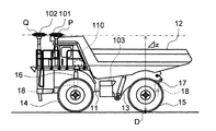
- FIG. 1 shows a schematic configuration of the dump truck according to the first embodiment of the present invention.
- the dump truck shown in this figure includes a frame 11, a cargo bed (body) 12 attached to the frame so as to be raised and lowered, and two trucks installed at predetermined intervals in the width direction of the vehicle for raising and lowering the cargo bed 12.
- FIG. 2 is a top view schematically showing the structure of the dump truck shown in FIG.
- an orthogonal coordinate system B having an origin in the dump truck and having three axes of the longitudinal axis y, the lateral axis x, and the vertical axis z is set (in FIG. The origin is set at the center of the dump truck.)
- this coordinate system may be referred to as a vehicle coordinate system B.
- the angle formed by the front and rear axes y and the horizontal plane when the dump truck rotates about the left and right axis x is defined as the pitch angle ⁇ , and when the dump truck rotates about the front and rear axes y, the left and right axis x forms the horizontal plane.
- the angle is the roll angle ⁇ .
- the yaw angle ⁇ which is the rotation angle of the vertical axis z is an azimuth angle.
- two GPS receivers 101 and 102 are arranged at an interval of ⁇ x in the vehicle left-right direction (x-axis direction), and are further shifted from each other by ⁇ y in the vehicle front-rear direction (y-axis direction).
- ⁇ x may be set larger than the vehicle width.
- the points whose positions are detected by the two GPS receivers 101 and 102 are points P and Q, respectively.
- the line segment PQ connecting the two points P and Q is parallel to any of the three axes x, y, and z related to the vehicle coordinate system B. Therefore, by acquiring the positions of points P and Q and a reference point D to be described later, the roll angle ⁇ , pitch angle ⁇ , and yaw angle ⁇ of the dump truck can be specified.
- Navigation signals from GPS satellites received by the GPS receivers 101 and 102 are periodically output to the computer 110, and the computer 110 receives points P and P based on the navigation signals input from the GPS receivers 101 and 102.
- a process for estimating the position of Q is performed.
- the fixing method is not particularly limited as long as the GPS receivers 101 and 102 can be fixed relative to the frame 11 so as not to move relative to each other.
- the GPS receivers 101 and 102 may be installed substantially vertically on a beam-like member that protrudes substantially horizontally from the outer wall of the dump truck.
- ground plane a portion (ground plane) where the four rear wheels 15 are in contact with the ground
- the ground plane C is represented by a region surrounded by a rectangular broken line.
- the dump truck according to the present embodiment includes four rear wheels 15, there are four ground contact surfaces C, and a point arbitrarily selected from the four ground contact surfaces C is a reference point (ground contact point) D.
- the reference point D is set on a straight line obtained by projecting the axle of the rear wheel on the ground contact surface C of the rear wheel 15d located at the right end of the vehicle.
- each ground plane C is indicated by a rectangle, but this is merely a schematic illustration of the ground plane C and is not intended to limit the outline of the ground plane C.
- the reference point D may be arbitrarily selected from the actual contact surface between the tire and the ground.
- the two GPS receivers 101 and 102 are arranged with their positions adjusted so that only one perpendicular line can be lowered from the reference point D to the line segment PQ. ing. From the viewpoint of reducing the accuracy of the roll angle or the pitch angle with respect to the calculation of the posture of the dump truck, it is possible to adjust the position of the reference point D so that the perpendicular foot from the reference point D to the line segment PQ is positioned on the line segment PQ. preferable.
- the angle formed by the vector PQ from the point P to the point Q with the longitudinal axis y is denoted by ⁇ .
- the two GPS receivers 101 and 102 are installed so that the points P and Q are located at the same height.
- the posture calculation of the dump truck which will be described later, becomes easier as compared with the case where the two GPS receivers are installed at different heights.
- the dump truck includes two front wheels, that is, a left front wheel 14a and a right front wheel 14b, and the front suspension 16a related to the left front wheel 14a and the right front wheel 14b.
- a front suspension 16b is provided.
- a total of four wheels 15a, 15b, 15c, 15d are provided as rear wheels, of which two rear wheels 15a, 15b are arranged on the left side of the vehicle, and the remaining two rear wheels 15c, 15d are vehicles.
- the rear suspension 17a is related to the left rear wheel groups 15a and 15b
- the rear suspension 17b is related to the right rear wheel groups 15c and 15d.
- the symbol G shown in FIG. 2 indicates the center of gravity of the dump truck.
- the center of gravity G may move slightly in the vertical direction in FIG. 2 along the y-axis depending on the loading amount of the loading platform 12, but the rear wheel 15 rather than the front wheel 14 even if the loading amount of the loading platform 12 changes. Always present in close position. That is, the rear wheel 15 is always present near the center of gravity G.
- FIG. 3 is a configuration diagram of the computer 110.
- a computer 110 includes an arithmetic processing unit (for example, CPU) 104 as arithmetic means for executing various programs, and a storage device as storage means for storing various data including the programs.
- arithmetic processing unit for example, CPU
- a storage device as storage means for storing various data including the programs.
- semiconductor memory such as ROM, RAM and flash memory, and magnetic storage devices such as hard disk drives
- An input / output interface 111 for performing output control is provided.
- a display device for example, a liquid crystal monitor or the like
- the processing result of the arithmetic processing device 104 for example, the calculation result of the attitude of the dump truck
- the computer 110 is connected to the GPS receivers 101 and 102, the leveling sensor 18 for detecting the displacement of the rear suspension 17b related to the right rear wheels 15c and 15d, and the inertial measurement device 103 via the input / output interface 111.
- the output values from the devices 101, 102, 18, 103 are input to the computer 110.
- a map indicating the shape and gradient of the traveling path of the dump truck is stored as data (map data).
- the shape of the travel path is represented by points (hereinafter referred to as nodes) and lines (hereinafter referred to as links), and a topological map database is configured in the storage device 106.
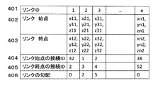
- FIG. 4 shows the data structure of the topological map database related to the storage device 106.
- the storage device 106 is individually given to all the links constituting the map (the total number of links is n), and a link ID 401 uniquely representing each link and a corresponding link ID are provided.
- a link start point 402 indicating the coordinates of the start point (node) of the link having, a link end point 403 indicating the coordinates of the end point (node) of the link having the corresponding link ID, and other links to which the start point of the link having the corresponding link ID is connected
- a connection ID 404 indicating a link ID
- a connection ID 405 indicating an ID of another link to which an end point of the link having the corresponding link ID is connected
- a gradient 406 is stored.
- the coordinates of the nodes related to the link start point 402 and the link end point 403 are indicated by three-dimensional coordinates in the ground coordinate system O (see FIGS. 6 and 7) set on the ground (earth) such as the world geodetic system.
- the link gradient (road gradient) in this embodiment is defined by the angle between the link and the horizontal plane, but instead is defined by the height of two nodes located at both ends of the link. Also good.
- FIG. 5 is a flowchart of the dump truck attitude calculation process executed by the computer 110.
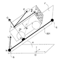
- FIG. 6 is a diagram (model diagram) in which the dump truck shown in FIG. 1 is modeled.
- the attitude calculation process of FIG. 5 will be described with reference to FIG.
- the coordinate system O is a three-dimensional coordinate system (ground coordinate system) set on the ground
- the dump truck is traveling on the traveling surface J including the link 601.
- the link 601 forms part of the traveling path of the dump truck, and has an individual link ID, a start point S, and an end point E.
- an inclination angle of the link 601 with respect to the horizontal plane is ⁇ .
- ⁇ z indicates the distance from the points P and Q to the running surface J, and in the example of FIG. 6, the reference point (contact point) D is set as the ground side reference.
- ⁇ z can be calculated by detecting a change in vehicle height at the position of the rear wheel 15d where the reference point is set.
- the length of the suspension 17b associated with the rear wheel 15d is detected by the leveling sensor 18, and the height distance from the upper end of the suspension 17b to the points P and Q (the distance is a constant value) is detected.
- ⁇ z is calculated.
- the distance from one of the two points P and Q to the traveling surface may be set to ⁇ z.
- the loading amount of the loading platform 12 may be detected by detecting the suspension pressure with a pressure sensor, and ⁇ z may be calculated from the change in the loading amount.
- point T is a point advanced from reference point D by ⁇ z in the normal direction of running surface J.
- the plane including the two points P and Q and the point T is parallel to the traveling plane J, and the normal vector U of the plane is the outer product of the vectors TQ and TP from the point T toward the two points P and Q.
- the computer 110 first calculates the positions (vectors OP and OQ) of the points P and Q in the ground coordinate system O based on the input values from the GPS receivers 101 and 102. (Step 100).
- the computer 110 identifies the link 601 related to the travel path on which the dump truck is currently traveling from the positions of the points P and Q, and acquires the start point, the end point, and the gradient ⁇ of the link from the storage device 106.
- the position of the point P or the point Q is regarded as the own vehicle position
- the link start point or link end point existing within a predetermined range from the own vehicle position is searched in the storage device 106, and the link start point or link end point is searched. All the link IDs associated with are acquired.
- a perpendicular line is drawn from the own vehicle position for all the links having the acquired ID, and the link having the shortest perpendicular length is selected as the link indicating the currently running surface.
- the start point, end point, and gradient ⁇ of the selected link are acquired from the storage device 106 (step 110).
- the computer 110 calculates the position of the reference point D based on the positions of the points P and Q acquired in step 100.
- the position of the reference point D can be obtained as follows.
- a vector SE is defined from the start point S and the end point E of the link 601, and a normal direction vector orthogonal to the vector SE on the traveling plane J is defined as a vector NL. Since the vector OD indicating the position of the reference point D in the ground coordinate system O exists on a plane (running plane J) spanned by the vector SE and the vector NL, the following equation (2) is used by using unknown variables s and t. ).
- the distance from the point P to the reference point D is a scalar of the difference between the vector OD and the vector OP and can be expressed as the following formula (3) using the above formula (2). it can.
- the distance from the point Q to the reference point D is a scalar of the difference between the vector OD and the vector OQ, and is expressed by the following equation (4) using the above equation (2). be able to.
- the inventors have determined that the center of gravity G (see FIG. 2) of the dump truck moves slightly along the longitudinal axis y according to the load weight of the loading platform 12, and the axle of the rear wheel 15 Focusing on the fact that the rear wheel 15 is always in contact with the ground even if the position and load weight of the dump truck change, there is no change in the position in the vicinity.
- a reference point D is set at the contact portion (ground contact surface C) between the rear wheel 15 and the ground, and the reference point D is set as a fixed end and lowered from the reference point D to the line segment PQ. We thought that the perpendicular could swing.
- the vertical leg drawn from the reference point D to the line segment PQ is K, as shown in FIG. 7, even if the posture of the dump truck changes, the length of the line segment DK around the reference point D is It can be assumed that the point K is always located on the surface of the sphere 610 having a radius.
- the line segment DK can rotate around its long axis, and the line segment PQ can have an angle with respect to the horizontal plane.
- the distance from the reference point D to the two points P and Q (the scalars of the vectors PD and QD) is constant even when the dump truck posture changes, and these distances can be calculated in advance. It is.
- the scalar of the vector PD and the scalar of the vector QD are known values, and the vector OP and the vector OQ have already been acquired in step 100, so that two sets of s from the above-described equations (2) and (3). , T can be determined (step 120). Furthermore, assuming that the dump truck does not roll over, the solution that satisfies the following equation among the two sets of s and t is the solution. In the following formula, sgn indicates a sign.
- OD is calculated from s and t obtained from the above two formulas (3) and (4) and formula (1) (step 130).
- the positions of the three points P, Q, and D are determined. Therefore, when the traveling road has a gradient, the posture of the dump truck can be obtained by appropriately considering ⁇ .
- the computer 110 detects the length of the suspension 17b associated with the rear wheel 15d by the leveling sensor 18, calculates the ⁇ z by adding the height distance from the upper end of the suspension 17b to the points P and Q, T is determined (step 140).
- the computer 110 calculates the normal vector U by taking the outer product of the two vectors TQ and TP from the point T determined in step 140 to the two points P and Q as shown in the above equation (1). (Step 150). After calculating the vector U, the computer 110 obtains the roll angle ⁇ , the pitch angle ⁇ , and the yaw angle ⁇ by using the following equations (step 160).
- the yaw angle ⁇ can be calculated from the vector PQ
- the pitch angle ⁇ can be calculated from the yaw angle ⁇ and the normal vector U
- the roll angle ⁇ can be calculated from the yaw angle ⁇ and the normal vector U.
- step 100 may be controlled by a timer so that the timing at which the new posture calculation process is started after returning from step 160 to step 100 is a constant interval. Further, in the respective arithmetic processes shown in FIG. 5, as long as the same arithmetic result is obtained, the order of the respective processes may be changed, or a plurality of processes may be simultaneously processed (parallel processing).
- the posture of the dump truck can be accurately estimated by using only two position estimation devices (GPS receivers 101 and 102).
- the time series information of the positions of the points P and Q obtained via the GPS receivers 101 and 102 is stored in the storage device 106, and the position is determined based on the time series information.
- a feature is that a movement vector of data is calculated, and a gradient ⁇ of a road on which the dump truck travels is calculated based on the movement vector.
- the present embodiment and the first embodiment are different in the data structure of the storage device 106 and the point that the gradient ⁇ is calculated by the computer 110, the other configurations are the first including the attitude calculation process. Since this is the same as the embodiment, the description is omitted.
- FIG. 8 is a diagram showing a portion related to the time series information of the positions of the points P and Q in the data structure of the storage device 106 according to the second embodiment of the present invention.
- the time sequence 701 in which the times at which the positions of the points P and Q are detected is recorded in time series, and the times at which the time sequence 701 is associated.
- a position column 702 in which the position of the point P is recorded and a position column 703 in which the position of the point Q at each time according to the time column 710 is recorded are stored.
- There are times when there is no output value from the GPS receivers 101 and 102, and in this case, a character string FF indicating that the position of the point P or the point Q could not be calculated is input at that time.
- a gradient calculation process executed by the computer 110 according to this embodiment instead of step 110 shown in FIG. 5 will be described.
- the computer 110 When calculating the gradient, the computer 110 outputs both the positions of the two points P and Q at the current time and the positions of the two points P and Q that are a predetermined number of samples before the current time and outputs the two points P and Q. Although there are both, a total of four positions are extracted from the storage device 106. For example, when the positions of the four points are shown in the example of FIG. 8, positions 704, 705, 706, and 707 correspond to this.
- the computer 110 draws the first and second line segments by connecting the two points P and Q related to the same time at the four extracted points, and further, among the first line segments.
- a third line segment (movement vector of position data) is drawn by connecting the point and the midpoint of the second line segment, and an inclination angle with respect to the horizontal plane of the third line segment is calculated as a road gradient. Note that the gradient calculation processing according to the present embodiment is based on the assumption that there is no cant angle.
- FIG. 9 is a model diagram of the position estimation results of the points P and Q.
- FIG. 9 shows four points P (0), Q (0), P (3), and Q (3).
- P (0) and Q (0) are points P and Q at the current time.
- P (3) and Q (3) indicate the positions of points P and Q three samples before.
- the midpoint of the line segment PQ obtained from the two points P (0) and Q (0) at the current time is R0, and the line segment PQ obtained from the two points P (0) and Q (0) three samples before is obtained.
- Let the midpoint be R1.
- the points R0 and R1 and the gradient ⁇ [rad] at this time can be obtained by the following equation.
- the computer 110 can calculate the gradient ⁇ at the traveling point of the dump truck based on the current and past position data of the points P and Q. Therefore, the gradient ⁇ and the three points P, The attitude of the dump truck can be calculated based on the current positions of Q and D. As a result, even when the slope information of the traveling path of the dump truck is not included in the map data (for example, when the slope is not measured at the time of creating the map data), the posture of the dump truck in consideration of the road slope is maintained. It can be calculated.
- the leveling sensor 18 for detecting the length of the rear suspension 17b is used.
- the pressure sensor 18 for detecting the pressure of the fluid (hydraulic pressure) in the suspension 17b by the pressure sensor.
- the loading weight of the loading platform 12 may be estimated, and ⁇ z may be estimated based on the loading weight.
- the GPS receivers 101 and 102 are used to estimate the position of the dump truck.
- a receiver that receives navigation signals from other satellites is installed in the dump truck in the same manner, and positioning is performed based on the navigation signals.
- the position of the dump truck may be estimated by configuring another satellite positioning system that performs the above.
- the reference point D when detecting a minute posture change, it is preferable to make the length of the perpendicular line from the point D to the line segment PQ as long as possible. Therefore, it is preferable to set the reference point D at a position farthest from the line segment PQ. That is, in the example of FIG. 2, it is preferable to set the reference point at the lower right vertex in the figure on the ground contact surface C of the rear wheel 15d.
- the reference point D is set on the ground contact surface C of the rightmost rear wheel 15d. From the viewpoint of reducing as much as possible the error that occurs when calculating the attitude of the dump truck, the center of gravity of the dump truck is more than that of the other rear wheels. It is preferable to set the reference point D at a position closest to the center of gravity G on the ground contact surface C of the two wheels 15b and 15c that are close to G (see FIG. 2). When the reference point D is set in this way, the reference point D can be brought close to the center of gravity G that is the swing center of the dump truck, and the calculation can be performed in a state close to the actual operation of the dump truck, so that the error can be reduced.
- the two points P and Q and the reference point D are set so that the triangle having the points P, Q and D as vertices becomes a regular triangle. That is, it is preferable to set each point so that the lengths of the line segments PQ, QD, and DP are equal. In this way, errors generated when calculating the attitude of the dump truck can be evenly distributed to the roll angle ⁇ and the pitch angle ⁇ , so that the accuracy of the calculated attitude of the dump truck is improved overall.
- the attitude of the dump truck is calculated by the computer 110 mounted on the dump truck.
- the computer performs traveling control of a plurality of dump trucks that autonomously travel.
- the positions of the points P and Q may be input from the dump truck via a wireless communication device or the like, and the attitude may be calculated by the computer.
- the present invention is not limited to the above-described embodiment, and includes various modifications within the scope not departing from the gist thereof.
- the present invention is not limited to the one having all the configurations described in the above embodiment, and includes a configuration in which a part of the configuration is deleted.
- part of the configuration according to one embodiment can be added to or replaced with the configuration according to another embodiment.
- each configuration relating to the above-described computer, functions and execution processing of each configuration, and the like are realized by hardware (for example, logic for executing each function is designed by an integrated circuit). Also good.
- the configuration related to the computer may be a program (software) that realizes each function related to the configuration of the control device by being read and executed by an arithmetic processing device (for example, a CPU).
- Information related to the program can be stored in, for example, a semiconductor memory (flash memory, SSD, etc.), a magnetic storage device (hard disk drive, etc.), a recording medium (magnetic disk, optical disc, etc.), and the like.
- control line and the information line are shown to be understood as necessary for the description of the embodiment, but all the control lines and information lines related to the product are not necessarily included. It does not always indicate. In practice, it can be considered that almost all the components are connected to each other.
Landscapes
- Engineering & Computer Science (AREA)
- Radar, Positioning & Navigation (AREA)
- Remote Sensing (AREA)
- Physics & Mathematics (AREA)
- General Physics & Mathematics (AREA)
- Transportation (AREA)
- Mechanical Engineering (AREA)
- Computer Networks & Wireless Communication (AREA)
- Navigation (AREA)
- Position Fixing By Use Of Radio Waves (AREA)
- Control Of Position, Course, Altitude, Or Attitude Of Moving Bodies (AREA)
Abstract
Priority Applications (3)
| Application Number | Priority Date | Filing Date | Title |
|---|---|---|---|
| CN201480010452.6A CN105074382B (zh) | 2013-09-13 | 2014-07-09 | 自卸卡车 |
| EP14843761.9A EP3045862B1 (fr) | 2013-09-13 | 2014-07-09 | Camion benne |
| US14/772,909 US9605959B2 (en) | 2013-09-13 | 2014-07-09 | Dump truck |
Applications Claiming Priority (2)
| Application Number | Priority Date | Filing Date | Title |
|---|---|---|---|
| JP2013-190676 | 2013-09-13 | ||
| JP2013190676A JP6095065B2 (ja) | 2013-09-13 | 2013-09-13 | ダンプトラック |
Publications (1)
| Publication Number | Publication Date |
|---|---|
| WO2015037319A1 true WO2015037319A1 (fr) | 2015-03-19 |
Family
ID=52665442
Family Applications (1)
| Application Number | Title | Priority Date | Filing Date |
|---|---|---|---|
| PCT/JP2014/068284 WO2015037319A1 (fr) | 2013-09-13 | 2014-07-09 | Camion benne |
Country Status (5)
| Country | Link |
|---|---|
| US (1) | US9605959B2 (fr) |
| EP (1) | EP3045862B1 (fr) |
| JP (1) | JP6095065B2 (fr) |
| CN (1) | CN105074382B (fr) |
| WO (1) | WO2015037319A1 (fr) |
Cited By (2)
| Publication number | Priority date | Publication date | Assignee | Title |
|---|---|---|---|---|
| US9952115B2 (en) | 2016-02-01 | 2018-04-24 | Caterpillar Inc. | Angle of repose detector for hauling machines |
| CN108137091A (zh) * | 2015-11-11 | 2018-06-08 | 日立建机株式会社 | 车轮的偏滑角推定装置及其方法 |
Families Citing this family (6)
| Publication number | Priority date | Publication date | Assignee | Title |
|---|---|---|---|---|
| WO2017200748A1 (fr) * | 2016-05-18 | 2017-11-23 | Graco Minnesota Inc. | Système de distribution de plusieurs composants à distributeurs multiples |
| JP6752168B2 (ja) * | 2017-02-27 | 2020-09-09 | 日立建機株式会社 | ダンプトラック及び後退支援装置 |
| EP3415390B1 (fr) | 2017-06-12 | 2024-03-27 | Hexagon Geosystems Services AG | Système d'assistance à la conduite pour faire reculer un véhicule de convoyage d'exploitation minière |
| WO2019017159A1 (fr) * | 2017-07-18 | 2019-01-24 | 株式会社小松製作所 | Dispositif d'identification de paramètre, dispositif de simulation et procédé d'identification de paramètre |
| DE102019129205A1 (de) * | 2019-10-29 | 2021-04-29 | Horsch Leeb Application Systems Gmbh | Landmaschine mit System zur Berechnung eines Geländerelief und Verfahren zum Betreiben einer Landmaschine |
| JPWO2021112078A1 (fr) * | 2019-12-02 | 2021-06-10 |
Citations (7)
| Publication number | Priority date | Publication date | Assignee | Title |
|---|---|---|---|---|
| JPH07244150A (ja) * | 1994-02-28 | 1995-09-19 | Fujita Corp | 重機の姿勢計測装置 |
| JP2002286829A (ja) * | 2001-03-27 | 2002-10-03 | Mitsubishi Motors Corp | 絶対位置推定装置 |
| US6671587B2 (en) * | 2002-02-05 | 2003-12-30 | Ford Motor Company | Vehicle dynamics measuring apparatus and method using multiple GPS antennas |
| US7400956B1 (en) * | 2003-03-20 | 2008-07-15 | Hemisphere Gps Inc. | Satellite position and heading sensor for vehicle steering control |
| JP2008216062A (ja) * | 2007-03-05 | 2008-09-18 | Japan Radio Co Ltd | 移動体姿勢計測装置 |
| JP2010190806A (ja) | 2009-02-20 | 2010-09-02 | Mitsubishi Electric Corp | 方位算出装置、方位算出装置の方位算出方法および方位算出プログラム |
| JP2012233353A (ja) | 2011-05-02 | 2012-11-29 | Komatsu Ltd | 油圧ショベルの較正システム及び油圧ショベルの較正方法 |
Family Cites Families (3)
| Publication number | Priority date | Publication date | Assignee | Title |
|---|---|---|---|---|
| US6191733B1 (en) * | 1999-06-01 | 2001-02-20 | Modular Mining Systems, Inc. | Two-antenna positioning system for surface-mine equipment |
| US7139651B2 (en) * | 2004-03-05 | 2006-11-21 | Modular Mining Systems, Inc. | Multi-source positioning system for work machines |
| DE102009046389A1 (de) * | 2009-11-04 | 2011-05-05 | Robert Bosch Gmbh | Verfahren zur Bestimmung einer Fahrzeugzustands- oder Kenngröße in einem Fahrzeug |
-
2013
- 2013-09-13 JP JP2013190676A patent/JP6095065B2/ja active Active
-
2014
- 2014-07-09 US US14/772,909 patent/US9605959B2/en active Active
- 2014-07-09 CN CN201480010452.6A patent/CN105074382B/zh active Active
- 2014-07-09 EP EP14843761.9A patent/EP3045862B1/fr active Active
- 2014-07-09 WO PCT/JP2014/068284 patent/WO2015037319A1/fr active Application Filing
Patent Citations (7)
| Publication number | Priority date | Publication date | Assignee | Title |
|---|---|---|---|---|
| JPH07244150A (ja) * | 1994-02-28 | 1995-09-19 | Fujita Corp | 重機の姿勢計測装置 |
| JP2002286829A (ja) * | 2001-03-27 | 2002-10-03 | Mitsubishi Motors Corp | 絶対位置推定装置 |
| US6671587B2 (en) * | 2002-02-05 | 2003-12-30 | Ford Motor Company | Vehicle dynamics measuring apparatus and method using multiple GPS antennas |
| US7400956B1 (en) * | 2003-03-20 | 2008-07-15 | Hemisphere Gps Inc. | Satellite position and heading sensor for vehicle steering control |
| JP2008216062A (ja) * | 2007-03-05 | 2008-09-18 | Japan Radio Co Ltd | 移動体姿勢計測装置 |
| JP2010190806A (ja) | 2009-02-20 | 2010-09-02 | Mitsubishi Electric Corp | 方位算出装置、方位算出装置の方位算出方法および方位算出プログラム |
| JP2012233353A (ja) | 2011-05-02 | 2012-11-29 | Komatsu Ltd | 油圧ショベルの較正システム及び油圧ショベルの較正方法 |
Non-Patent Citations (1)
| Title |
|---|
| See also references of EP3045862A4 |
Cited By (3)
| Publication number | Priority date | Publication date | Assignee | Title |
|---|---|---|---|---|
| CN108137091A (zh) * | 2015-11-11 | 2018-06-08 | 日立建机株式会社 | 车轮的偏滑角推定装置及其方法 |
| EP3375694A4 (fr) * | 2015-11-11 | 2019-07-17 | Hitachi Construction Machinery Co., Ltd. | Dispositif et procédé pour estimer l'angle de glissement d'une roue de véhicule |
| US9952115B2 (en) | 2016-02-01 | 2018-04-24 | Caterpillar Inc. | Angle of repose detector for hauling machines |
Also Published As
| Publication number | Publication date |
|---|---|
| US9605959B2 (en) | 2017-03-28 |
| JP6095065B2 (ja) | 2017-03-15 |
| JP2015055603A (ja) | 2015-03-23 |
| EP3045862A1 (fr) | 2016-07-20 |
| EP3045862B1 (fr) | 2020-03-18 |
| CN105074382B (zh) | 2017-08-04 |
| EP3045862A4 (fr) | 2017-07-12 |
| US20160010988A1 (en) | 2016-01-14 |
| CN105074382A (zh) | 2015-11-18 |
Similar Documents
| Publication | Publication Date | Title |
|---|---|---|
| JP6095065B2 (ja) | ダンプトラック | |
| JP6866424B2 (ja) | 装置の配向を計算するためのシステムおよび方法 | |
| US9026263B2 (en) | Automotive navigation system and method to utilize internal geometry of sensor position with respect to rear wheel axis | |
| CN103017763B (zh) | 状态估计设备和偏移更新方法 | |
| CN104198765B (zh) | 车辆运动加速度检测的坐标系转换方法 | |
| US9885575B2 (en) | Vehicle positioning | |
| AU2015200793B2 (en) | Compensating for acceleration induced inclination errors | |
| JP6976412B2 (ja) | 単一の位置センサを用いる回転プラットフォームのヨーおよび回転中心の決定方法 | |
| JP7060440B2 (ja) | 無人化施工システムおよびブルドーザ | |
| AU2015305864B9 (en) | Earthmoving machine comprising weighted state estimator | |
| US9580104B2 (en) | Terrain-based machine comprising implement state estimator | |
| Maeder et al. | Attitude estimation for vehicles with partial inertial measurement | |
| CN106370178A (zh) | 移动终端设备的姿态测量方法及装置 | |
| US10371522B2 (en) | Iterative estimation of centripetal accelerations of inertial measurement units in kinematic chains | |
| CN108718533A (zh) | 具有高程数据输入的无线惯性车辆导航 | |
| US9052391B2 (en) | Backup velocity estimation utilizing traction device speed | |
| CN109827572A (zh) | 一种检测车位置预测的方法及装置 | |
| US20230349699A1 (en) | Absolute heading estimation with constrained motion | |
| CN108088463A (zh) | 一种高度传感器辅助伪卫星定位的惯导初始对准方法 | |
| CN104864868A (zh) | 一种基于近距离地标测距的组合导航方法 | |
| CN111002991B (zh) | 一种车载导航信息处理的方法、装置及计算机存储介质 | |
| JP2023012798A (ja) | 作業機械 | |
| Brown et al. | Road bank estimation on uneven terrain for unmanned ground vehicles | |
| JP2024063671A (ja) | 車いす動作推定装置、車いす動作推定システム、車いす動作推定方法、及び車いす動作推定プログラム | |
| CN113900126A (zh) | 双天线位置确定方法及装置 |
Legal Events
| Date | Code | Title | Description |
|---|---|---|---|
| WWE | Wipo information: entry into national phase |
Ref document number: 201480010452.6 Country of ref document: CN |
|
| 121 | Ep: the epo has been informed by wipo that ep was designated in this application |
Ref document number: 14843761 Country of ref document: EP Kind code of ref document: A1 |
|
| REEP | Request for entry into the european phase |
Ref document number: 2014843761 Country of ref document: EP |
|
| WWE | Wipo information: entry into national phase |
Ref document number: 2014843761 Country of ref document: EP |
|
| WWE | Wipo information: entry into national phase |
Ref document number: 14772909 Country of ref document: US |
|
| NENP | Non-entry into the national phase |
Ref country code: DE |