WO2015037271A1 - Cap-equipped connector for medical use - Google Patents
Cap-equipped connector for medical use Download PDFInfo
- Publication number
- WO2015037271A1 WO2015037271A1 PCT/JP2014/062265 JP2014062265W WO2015037271A1 WO 2015037271 A1 WO2015037271 A1 WO 2015037271A1 JP 2014062265 W JP2014062265 W JP 2014062265W WO 2015037271 A1 WO2015037271 A1 WO 2015037271A1
- Authority
- WO
- WIPO (PCT)
- Prior art keywords
- female connector
- cap
- connector
- female
- boss
- Prior art date
Links
Images


Classifications
-
- A—HUMAN NECESSITIES
- A61—MEDICAL OR VETERINARY SCIENCE; HYGIENE
- A61M—DEVICES FOR INTRODUCING MEDIA INTO, OR ONTO, THE BODY; DEVICES FOR TRANSDUCING BODY MEDIA OR FOR TAKING MEDIA FROM THE BODY; DEVICES FOR PRODUCING OR ENDING SLEEP OR STUPOR
- A61M39/00—Tubes, tube connectors, tube couplings, valves, access sites or the like, specially adapted for medical use
- A61M39/20—Closure caps or plugs for connectors or open ends of tubes
Definitions
- the present invention relates to a connector with a medical cap that includes a female connector attached to an open end of a medical fluid line and a cap that covers the opening of the female connector.
- a medical fluid circuit such as an extracorporeal circulation circuit for blood purification is provided with a fluid line through which a medical fluid (for example, blood or the like) flows. Since other fluid lines may be connected to such a fluid line, a connector that can be connected to the open ends of other fluid lines is usually provided at the open ends of the fluid lines.
- a connector When the connector is a cylindrical female connector into which an open end of another medical fluid line is inserted, a cap may be attached to the female connector to prevent contamination.
- Patent Document 1 discloses a cap attached to such a female connector.
- the cap in Patent Document 1 has a cylindrical main body and a mounting portion protruding inside the main body, and the mounting portion has an outer shape in order from the base end side (the side far from the female connector).
- a certain flat part and a taper part which tapers toward the front end side (side near the female connector) are arranged in the flat part through the step part.
- a female screw that can be screwed with a male screw formed on the outer peripheral surface of the female connector is formed on the inner peripheral surface of the cap body.
- the inner surface of the female connector and the outer surface (flat portion) of the mounting portion are brought into close contact with each other by inserting the cap mounting portion to the back side of the female connector. It is possible to improve air tightness and liquid tightness.
- such a connector with a medical cap is subjected to heat treatment for sterilization with the cap attached to the female connector.
- the shape of the female connector may change depending on the material of the female connector.
- a material of the female connector for example, a soft material such as polyvinyl chloride (PVC) may be used.
- PVC polyvinyl chloride
- such a material is excellent in chemical resistance, but has a property of being easily heat-shrinkable.
- Patent Document 1 In order to avoid such a problem, heat treatment should be performed in a state in which only a part of the mounting portion enters the female connector without inserting the cap mounting portion to the back of the female connector.
- a female screw for attaching the cap to the female connector is formed continuously from the distal end to the proximal end of the cap body. Therefore, in the cap of Patent Document 1, it is difficult to pay attention to the insertion amount of the mounting portion when the cap is attached to the female connector, and the mounting portion may be inserted to the back side of the female connector.
- Patent Document 2 also discloses a cap that is attached to the female connector, but this cap is not considered to restrict the amount of insertion of the cap into the female connector.
- an object of the present invention is to provide a connector with a medical cap that has improved air tightness and liquid tightness when connected to other fluid lines.
- the connector with a cap of the present invention is a connector with a medical cap comprising a female connector attached to an open end of a medical fluid line, and a cap that covers the opening of the female connector.
- An entry portion that enters from the outside of the female connector to the first entry position inside the female connector by the operation of, and enters from the first entry position inside the female connector to the second entry position by the second operation,
- the first entry position includes an entry portion that forms a gap with the inner surface of the female connector.
- the cap is configured such that when the boss projecting from the cap reaches the first entry position, the cap is brought into contact with a part of the female connector, whereby the boss is formed by a first operation.
- a first restricting part that restricts further entry of the vehicle.
- the first operation is the axial direction of the cap with respect to the female connector (in this specification, “axis” refers to a center line of rotational movement when the outer cylinder rotates, “Axial direction” refers to an operation of moving the center line in the length direction), and the second operation rotates the cap around the axis relative to the female connector at the first entry position. Including the operation to be performed.
- the entry portion has an outer shape that decreases in diameter as it approaches the tip
- the female connector has an inner shape that decreases in diameter as it advances toward the back side.
- the cap has a disconnection preventing portion that restricts complete detachment of the boss portion from the inside of the female connector by contacting a part of the female connector.
- Another connector with a cap is a connector with a medical cap provided with a female connector attached to an open end of a medical fluid line, and a cap covering the opening of the female connector,
- An outer cylinder that covers the outer periphery of the female connector; a top that covers one end of the outer cylinder; and a boss that protrudes in the axial direction in the outer cylinder and enters the female connector;
- a boss having a gap with the inner surface of the female connector when entering the first entry position, and a portion of the female connector abutting when the boss enters the first entry position.
- a first restricting portion for restricting further entry of the boss portion and a female screw formed on the inner surface of the outer cylinder and screwed with a male screw formed on the outer peripheral surface of the female connector, When the part reaches the first entry position, it starts to be screwed with the female screw formed on the outer peripheral surface of the female connector, and the cap is rotated so that the boss part is located behind the first entry position. And a female screw guided to the side.
- the operation type when entering the first entry position is different from the operation type when entering from the first entry position to the second entry position.
- the amount of connection to the female connector can be clearly recognized, and when using a connector with a cap, it has the effect of improving air tightness and liquid tightness when connected to other fluid lines. .
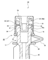
- FIG. 1 to 3 are cross-sectional views of a connector 10 with a medical cap according to an embodiment of the present invention.
- FIG. 1 is a sectional view before assembling the cap
- FIG. 2 is a sectional view after assembling the cap (first entry position)
- FIG. 3 is a sectional view in a usable state (second entry position).
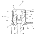
- FIG. 4 is a perspective view of the cap 20.
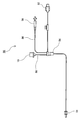
- FIG. 5 is a block diagram of the blood circuit 50 to which the connector with cap 10 is attached.
- the connector 10 with a cap is a female connector used in a medical fluid circuit such as an extracorporeal circulation circuit for blood purification connected to a dialysis apparatus for performing dialysis treatment.
- a medical fluid circuit such as an extracorporeal circulation circuit for blood purification connected to a dialysis apparatus for performing dialysis treatment.
- the female connector used for the venous blood circuit among the extracorporeal circulation circuits for blood purification will be described as an example.
- an extracorporeal circuit for blood purification is a dialyzer that purifies blood flowing through a blood circuit interposed between the arterial blood circuit and the venous blood circuit, and the arterial blood circuit and the venous blood circuit. It is configured.
- a shunt connector to which a puncture needle is connected is disposed at the distal end of the arterial blood circuit, and an iron-type blood pump and an air trap chamber for defoaming are respectively disposed in the middle. Connected to the inlet.
- FIG. 5 is a diagram showing a venous blood circuit 50 which is an example of a medical fluid circuit.
- a shunt connector 51 to which a puncture needle is connected is provided at the distal end of the venous blood circuit 50, an air trap chamber 54 for removing bubbles is provided in the middle, and a blood outlet port of the dialyzer is provided at the proximal end.
- a dialyzer lock connector 52 for connection is provided.
- a monitor line 56 is connected to the air trap chamber 54, and a connector 58 for connection with a venous pressure sensor is connected to the tip of the monitor line 56.
- the connector 10 with a cap is connected to the air trap chamber 54 via the female connector body 60.
- Another fluid line such as a syringe is connected to the female connector of the connector 10 with cap, and the chemical solution is introduced.
- the female connector can be closed with a cap to prevent contamination.
- the cap-attached connector 10 is roughly divided into a female connector 12 that can be connected to other fluid lines and a cap 20 that can close the female connector 12.
- the female connector 12 is made of a material having excellent chemical resistance, such as polyvinyl chloride (PVC).
- PVC polyvinyl chloride
- the female connector 12 has a substantially cylindrical shape, and its inner diameter is reduced as it advances toward the back side (depth direction). Therefore, the inner surface of the female connector 12 is a tapered surface.
- a male screw 16 is formed on the outer periphery of the female connector 12 so as to be screwed into the cap 20.
- the cap 20 is made of a hard material having excellent heat resistance, and examples thereof include polypropylene (PP) and polycarbonate (PC).
- the cap 20 has a substantially cylindrical shape enough to cover the female connector 12.
- the cap 20 covers the outer periphery of the female connector 12, the top 24 covers one end of the outer tube 22, and the shaft within the outer tube 22. It is roughly divided into a boss portion 26 protruding in the direction.
- the cap 20 is provided with a connection ring 28 that is inserted through the female connector body 60 and a connection plate 30 that connects the connection ring 28 and the main body of the cap 20.
- the cap 20 is attached to the female connector body 60 by inserting the female connector body 60 through the connection ring 28, and the female connector 12 is disposed at the open end of the female connector body 60. Thereafter, the cap 20 is connected to the female connector 12 so as to cover the opening of the female connector 12.
- the cap 20 and the female connector 12 connected to each other are subjected to heat treatment for sterilization in order to be used as the venous blood circuit 50.
- the state before the cap 20 and the female connector 12 are attached to the female connector body 60 while the cap 20 is connected to the female connector 12 that is, the state shown in FIG. 1) is referred to as “before assembly”.
- the state in which the cap 20 is connected to the female connector 12 for sterilization ie, the state shown in FIG. 2 is referred to as “after assembly”
- the venous blood circuit 50 is ready for use (ie, FIG. 3). Is referred to as “usable state”.
- the connection state of the cap and the female connector was the same before and after the heat treatment, that is, after assembly and in the usable state.
- the connector in the prior art allows the cap to be screwed into the female connector until the top of the cap hits the front end surface of the female connector, so that the boss portion has entered the inner wall of the female connector.
- heat treatment for sterilization was performed.
- the female connector obtained after the heat treatment has problems such as failure to ensure liquid tightness and air tightness with a male connector attached to another fluid line.
- connection amount of the cap 20 at the time of assembly can be clearly recognized, and as a result, the female connector 12 can be prevented from being unintentionally deformed. This will be described below.
- the cap 20 of this embodiment is roughly divided into the outer cylinder 22, the top 24, and the boss 26.
- An insertion port convex portion 32 that protrudes inward and extends around the entire circumference is provided at the tip of the outer cylinder 22.
- the insertion port convex portion 32 functions as a removal preventing portion that prevents the cap 20 from being removed (completely detached) from the female connector 12, and the inner diameter thereof is the maximum diameter of the female connector 12 (that is, the male screw 16).
- the outer diameter is slightly smaller.
- a female screw 36 that engages with the male screw 16 formed in the female connector 12 is located in the range from the tip side (side near the female connector 12) to the intermediate height. Is formed.
- the inner surface of the outer cylinder 22 is roughly divided into a female screw forming portion 37 in which the female screw 36 is formed and a smooth portion 38 in which the female screw 36 and the like are not formed.
- a central convex portion 34 that protrudes inward and extends all around is provided.
- the central convex portion 34 functions as a first restricting portion that restricts the amount of entry of the boss portion 26, and has an inner diameter that is slightly smaller than the maximum diameter of the female connector 12.
- the inner diameter of the smooth portion 38 is slightly larger than the maximum diameter of the female connector 12.
- the boss part 26 is a part that functions as an entry part that enters the inner surface of the female connector 12.
- the boss portion 26 has a stepped truncated cone shape that decreases in diameter as it approaches the tip and changes in a step shape in the middle.
- the step of the boss portion 26 is formed at substantially the same height as the central convex portion 34 of the outer cylinder 22, and the boss portion 26 is located on the tip side (side closer to the female connector 12) with the step as a boundary.
- the small-diameter portion 26a and the large-diameter portion 26b located on the base end side (the side far from the female connector 12).
- the step portion functions as a first restricting portion that restricts the entry of the boss portion 26, and the outer diameter of the boss portion 26 in the step portion is formed to be slightly smaller than the inner diameter of the tip of the female connector 12.
- the outer peripheral surface of the small diameter portion 26a and the inner surface of the female connector 12 The value is set such that a sufficient gap is formed between the two.
- the sufficient gap is not less than the amount of change in the inner diameter of the female connector 12 due to thermal contraction.
- the outer diameter of the large-diameter portion 26b is such that when the boss portion 26 enters the inner surface of the female connector 12 to the farthest side (base end side) (state of FIG. 3), The value is set such that the inner surfaces of the female connector 12 are in close contact with each other while being elastically deformed.
- the outer diameter of the cap 20 is larger than the inner diameter of the insertion port convex portion 32, so that the female connector 12 does not enter the outer cylinder 22.
- the male screw 16 is elastically deformed, the male screw 16 gets over the insertion port convex portion 32, and the female connector 12 enters the outer cylinder 22.
- the female connector 12 that has entered the outer tube 22 is positioned in a smooth portion 38 where the female screw 36 is not formed.
- the smooth portion 38 is larger than the maximum diameter of the male screw 16 of the female connector 12.
- the female connector 12 can move freely in the axial direction without any particular force. Further, when the female connector 12 enters the outer cylinder 22, the boss portion 26 enters the inner surface of the female connector 12. On the other hand, the female connector 12 that has once entered the outer cylinder 22 is prevented from being detached from the outer cylinder 22 by the insertion port convex portion 32.
- the boss portion 26 is in a state after assembling (state of FIG. 2) that remains at a position where a gap is formed between the boss portion 26 and the inner surface of the female connector 12.
- the entry position of the boss portion 26 at the time of assembly with respect to the inner wall surface of the female connector 12 is hereinafter referred to as a “first entry position”.
- the cap 20 and the female connector 12 are subjected to heat treatment for sterilization in that state.
- the female connector 12 made of PVC is thermally contracted by the heat treatment, the amount of connection of the cap 20 to the female connector 12 can be clearly recognized, so that the cap 20 and the female connector 12 are independent of the shape of the boss portion 26. It is possible to improve the airtightness or liquid tightness at the time of connection.
- a user rotates the cap 20 around the axis with respect to the female connector 12, and the male screw 16 of the female connector 12 and the female screw 36 of the outer cylinder 22 are screwed (screwed). To proceed.
- the steps of the female connector 12, the central convex portion 34, and the boss portion 26 are elastically deformed, and the female connector 12 gets over the central convex portion 34 and the boss portion 26 to Proceeding to the back side (the base end side of the cap 20), the boss portion 26 also enters the back side of the inner surface of the female connector 12 from the first entry position.
- the entry position of the boss portion 26 in the usable state with respect to the inner surface of the female connector 12 is hereinafter referred to as a “second entry position”.
- the cap 20 when the cap 20 is assembled to the female connector 12, the cap 20 is pushed into the female connector 12 in the axial direction so that the cap 20 can be used. At this time, an operation of rotating the cap 20 in the axial direction with respect to the female connector 12 is performed.
- the operation type performed for causing the boss portion 26 to enter the first entry position is different from the operation type performed for causing the boss portion 26 to enter the second entry position. Therefore, the assembler can clearly connect the cap 20 to the female connector 12 with a clear awareness of the amount of the cap 20 entering the female connector 12, and accidentally completely connects the cap 20 to the female connector 12 before heat treatment. Can be effectively prevented. As a result, unintended shape deformation of the female connector 12 can be prevented.
- the central projection 34 is provided on the outer cylinder 22 in order to prevent the cap 20 from coming off.
- the cap 20 is configured such that a part of the cap 20 abuts a part of the female connector 12. If the disconnection is prevented, the central convex portion 34 may be provided on another portion, for example, the outer peripheral surface of the female connector 12 or the like. Similarly, the position and shape of the convex portion for temporarily stopping the boss portion 26 at the first entry position may be changed as appropriate.
- the boss portion 26 and the inner surface of the female connector 12 are brought into close contact with each other at the second approach position, but liquid tightness and air tightness are not required as a function of the connector 10 with a cap.
- the boss portion 26 and the inner surface of the female connector need not be in close contact at the second entry position.
- the cap-equipped connector 10 used in the extracorporeal circulation circuit for blood purification has been described as an example.
- the technique of the present embodiment is a medical-cap-equipped connector 10 that requires heat treatment in advance. If so, it may be applied to another connector 10 with a cap.
- connection connector 10 connector with cap, 12 female connector, 16 male thread, 20 cap, 22 outer cylinder, 24 top, 26 boss, 28 connection ring, 30 connection plate, 32 insertion slot convex part, 34 central convex part, 36 female thread , 40 tip outer peripheral edge, 41 tip inner peripheral edge, 50 vein side blood circuit, 51 shunt connector, 52 dialyzer lock connector, 54 air trap chamber, 56 monitor line, 58 connection connector, 60 female connector body.
Abstract
This cap-equipped connector (10) is provided with a female connector (12) for attachment an open end of a medical fluid line, and a cap (20) for covering the opening of the female connector (12). The cap (20) has a boss part (26), between which part and the inside surface of the female connector (12) a gap is formed at a first position of advance, the boss part (26) being advanced by a first operation from the outside of the female connector (12) to the first position of advance situated inside the female connector (12), and being advanced by a second operation from the first position of advance to a second position of advance situated inside the female connector (12).
Description
本発明は、医療用流体ラインの開口端に取り付けられるメスコネクタと、前記メスコネクタの開口を覆うキャップとを備えた医療用キャップ付コネクタに関する。
The present invention relates to a connector with a medical cap that includes a female connector attached to an open end of a medical fluid line and a cap that covers the opening of the female connector.
血液浄化用体外循環回路等の医療用流体回路には、医療用流体(例えば血液等)が流れる流体ラインが設けられている。かかる流体ラインには、他の流体ラインが接続されることがあるため、通常、流体ラインの開口端には、他の流体ラインの開口端が接続可能なコネクタが設けられている。前記コネクタが、他の医療用流体ラインの開口端が挿し込まれる筒状のメスコネクタである場合、当該メスコネクタには、汚染防止のために、キャップが取り付けられることがある。
A medical fluid circuit such as an extracorporeal circulation circuit for blood purification is provided with a fluid line through which a medical fluid (for example, blood or the like) flows. Since other fluid lines may be connected to such a fluid line, a connector that can be connected to the open ends of other fluid lines is usually provided at the open ends of the fluid lines. When the connector is a cylindrical female connector into which an open end of another medical fluid line is inserted, a cap may be attached to the female connector to prevent contamination.
特許文献1には、かかるメスコネクタに装着されるキャップが開示されている。特許文献1におけるキャップは、筒状の本体と、当該本体の内部に突設された装着部を有しており、装着部は、基端側(メスコネクタから遠い側)から順に、外形がほぼ一定の平坦部と、平坦部に段部を介して先端側(メスコネクタに近い側)に向けて先細りのテーパ部が並ぶ形状となっている。また、キャップ本体の内周面には、メスコネクタの外周面に形成された雄ネジと螺合可能な雌ネジが形成されている。かかるキャップによれば、メスコネクタがルアーテーパ-を有する場合でも、キャップの装着部をメスコネクタの奥側まで挿入すれば、メスコネクタの内表面と装着部の外表面(平坦部)とを密着させることができ、気密性や液密性を向上させることができる。
Patent Document 1 discloses a cap attached to such a female connector. The cap in Patent Document 1 has a cylindrical main body and a mounting portion protruding inside the main body, and the mounting portion has an outer shape in order from the base end side (the side far from the female connector). A certain flat part and a taper part which tapers toward the front end side (side near the female connector) are arranged in the flat part through the step part. Further, a female screw that can be screwed with a male screw formed on the outer peripheral surface of the female connector is formed on the inner peripheral surface of the cap body. According to such a cap, even when the female connector has a luer taper, the inner surface of the female connector and the outer surface (flat portion) of the mounting portion are brought into close contact with each other by inserting the cap mounting portion to the back side of the female connector. It is possible to improve air tightness and liquid tightness.
ところで、こうした医療用キャップ付コネクタは、キャップをメスコネクタに取り付けた状態で、滅菌のための熱処理が施される。この熱処理の際に、メスコネクタの材質によっては、その形状が変化することがあった。メスコネクタの材質として、例えば、ポリ塩化ビニル(PVC)等の軟質材料を使用することがあるが、かかる材料は、耐薬性に優れる一方で、熱収縮しやすいという性質を有している。
By the way, such a connector with a medical cap is subjected to heat treatment for sterilization with the cap attached to the female connector. During this heat treatment, the shape of the female connector may change depending on the material of the female connector. As a material of the female connector, for example, a soft material such as polyvinyl chloride (PVC) may be used. However, such a material is excellent in chemical resistance, but has a property of being easily heat-shrinkable.
しかし、軟質材料からなるメスコネクタに、特許文献1に記載されているようなキャップを取り付けたまま熱処理を施した場合は、メスコネクタが熱収縮する過程で、当該メスコネクタの内表面が装着部の外表面に当たり、当該装着部の外表面に沿った形状に変形してしまうことになる。このように変形したメスコネクタは、他の流体ラインへの接続時に、気密性や液密性が不十分な可能性を有している。
However, when heat treatment is performed on a female connector made of a soft material with a cap as described in Patent Document 1, the inner surface of the female connector is attached to the mounting portion in the process of thermal contraction. Will be deformed into a shape along the outer surface of the mounting portion. The female connector thus deformed may have insufficient airtightness or liquid tightness when connected to another fluid line.
かかる問題を避けるためには、キャップの装着部をメスコネクタの奥側まで挿入せず、装着部の一部のみがメスコネクタ内部に入り込んだ状態で、熱処理を施せばよい。しかし、特許文献1のキャップは、当該キャップをメスコネクタに装着するための雌ネジが、キャップ本体の先端から基端まで連続して形成されている。そのため、特許文献1のキャップにおいては、キャップをメスコネクタに取り付ける際に、装着部の挿入量に留意することが難しく、装着部をメスコネクタの奥側まで挿入してしまう可能性があった。また、特許文献2にもメスコネクタに装着されるキャップが開示されているが、このキャップも、キャップのメスコネクタに対する挿入量を規制することは考慮されていない。
In order to avoid such a problem, heat treatment should be performed in a state in which only a part of the mounting portion enters the female connector without inserting the cap mounting portion to the back of the female connector. However, in the cap of Patent Document 1, a female screw for attaching the cap to the female connector is formed continuously from the distal end to the proximal end of the cap body. Therefore, in the cap of Patent Document 1, it is difficult to pay attention to the insertion amount of the mounting portion when the cap is attached to the female connector, and the mounting portion may be inserted to the back side of the female connector. Patent Document 2 also discloses a cap that is attached to the female connector, but this cap is not considered to restrict the amount of insertion of the cap into the female connector.
そこで、本発明では、他の流体ラインとの接続時に、気密性や液密性を向上させた医療用キャップ付コネクタを提供することを課題とする。
Therefore, an object of the present invention is to provide a connector with a medical cap that has improved air tightness and liquid tightness when connected to other fluid lines.
本発明のキャップ付コネクタは、医療用流体ラインの開口端に取り付けられるメスコネクタと、前記メスコネクタの開口を覆うキャップと、を備えた医療用キャップ付コネクタであって、前記キャップは、第一の操作により前記メスコネクタ外部から前記メスコネクタ内部の第一進入位置まで進入し、第二の操作により前記メスコネクタ内部の前記第一進入位置から第二進入位置まで進入する進入部であって、前記第一進入位置において、前記メスコネクタの内面との間に間隙を形成する進入部を有する、ことを特徴とする。
The connector with a cap of the present invention is a connector with a medical cap comprising a female connector attached to an open end of a medical fluid line, and a cap that covers the opening of the female connector. An entry portion that enters from the outside of the female connector to the first entry position inside the female connector by the operation of, and enters from the first entry position inside the female connector to the second entry position by the second operation, The first entry position includes an entry portion that forms a gap with the inner surface of the female connector.
好適な態様では、前記キャップは、当該キャップに突設されたボス部が前記第一進入位置に到達した際に、前記メスコネクタの一部と当接することにより、第一の操作による前記ボス部の更なる進入を規制する第一規制部を有する。他の好適な態様では、前記第一の操作は、前記キャップを前記メスコネクタに対して軸方向(本明細書において「軸」とは外筒が回転する際に回転運動の中心線をいい、「軸方向」とは前記中心線の長さ方向をいう)に移動させる操作であり、前記第二の操作は、前記第一進入位置において、前記キャップを前記メスコネクタに対して軸周りに回転させる操作を含む。さらに他の好適な態様では、前記進入部は、先端に近づくにつれて縮径する外形を有し、前記メスコネクタは、奥側に進むにつれて縮径する内形を有する。また、さらに他の好適な態様では、前記キャップは、前記メスコネクタの一部と当接することにより、前記ボス部の前記メスコネクタ内部から完全離脱を規制する抜け防止部を有する。
In a preferred aspect, the cap is configured such that when the boss projecting from the cap reaches the first entry position, the cap is brought into contact with a part of the female connector, whereby the boss is formed by a first operation. A first restricting part that restricts further entry of the vehicle. In another preferred aspect, the first operation is the axial direction of the cap with respect to the female connector (in this specification, “axis” refers to a center line of rotational movement when the outer cylinder rotates, "Axial direction" refers to an operation of moving the center line in the length direction), and the second operation rotates the cap around the axis relative to the female connector at the first entry position. Including the operation to be performed. In still another preferred aspect, the entry portion has an outer shape that decreases in diameter as it approaches the tip, and the female connector has an inner shape that decreases in diameter as it advances toward the back side. In still another preferred aspect, the cap has a disconnection preventing portion that restricts complete detachment of the boss portion from the inside of the female connector by contacting a part of the female connector.
他の本発明であるキャップ付コネクタは、医療用流体ラインの開口端に取り付けられるメスコネクタと、前記メスコネクタの開口を覆うキャップと、を備えた医療用キャップ付コネクタであって、前記キャップは、前記メスコネクタの外周を覆う外筒と、外筒の一端を覆う天部と、前記外筒内において軸方向に突出し、前記メスコネクタの内部に進入するボス部であって、前記メスコネクタ内部の第一進入位置まで進入した際に前記メスコネクタ内面との間に間隙を有するボス部と、前記ボス部が前記第一進入位置まで進入した際に、前記メスコネクタの一部と当接することで前記ボス部の更なる進入を規制する第一規制部と、前記外筒の内面に形成され、前記メスコネクタの外周面に形成された雄ネジと螺合する雌ネジであって、前記ボス部が前記第一進入位置まで到達した際に、前記メスコネクタの外周面に形成された雌ネジと螺合開始し、前記キャップを回転させることにより、前記ボス部を前記第一進入位置より奥側に案内する雌ネジと、を有することを特徴とする。
Another connector with a cap according to the present invention is a connector with a medical cap provided with a female connector attached to an open end of a medical fluid line, and a cap covering the opening of the female connector, An outer cylinder that covers the outer periphery of the female connector; a top that covers one end of the outer cylinder; and a boss that protrudes in the axial direction in the outer cylinder and enters the female connector; A boss having a gap with the inner surface of the female connector when entering the first entry position, and a portion of the female connector abutting when the boss enters the first entry position. A first restricting portion for restricting further entry of the boss portion, and a female screw formed on the inner surface of the outer cylinder and screwed with a male screw formed on the outer peripheral surface of the female connector, When the part reaches the first entry position, it starts to be screwed with the female screw formed on the outer peripheral surface of the female connector, and the cap is rotated so that the boss part is located behind the first entry position. And a female screw guided to the side.
本発明によれば、第一進入位置まで進入する際の操作種類と、第一進入位置から第二進入位置まで進入する際の操作種類とが異なっているため、キャップ付コネクタの組立時にはキャップのメスコネクタへの接続量を明確に意識することができ、また、キャップ付コネクタの使用時には他の流体ラインとの接続時に気密性や液密性を向上させることができるという効果を有するものである。
According to the present invention, the operation type when entering the first entry position is different from the operation type when entering from the first entry position to the second entry position. The amount of connection to the female connector can be clearly recognized, and when using a connector with a cap, it has the effect of improving air tightness and liquid tightness when connected to other fluid lines. .
以下、本発明の実施形態について図面を参照して説明する。図1~図3は、本発明の実施形態である医療用キャップ付コネクタ10の断面図である。このうち、図1はキャップ組付前における断面図、図2はキャップ組付後(第一進入位置)における断面図、図3は使用可能状態(第二進入位置)における断面図である。また、図4はキャップ20の斜視図である。さらに、図5はキャップ付コネクタ10が取り付けられた血液回路50の構成図である。
Hereinafter, embodiments of the present invention will be described with reference to the drawings. 1 to 3 are cross-sectional views of a connector 10 with a medical cap according to an embodiment of the present invention. Among these, FIG. 1 is a sectional view before assembling the cap, FIG. 2 is a sectional view after assembling the cap (first entry position), and FIG. 3 is a sectional view in a usable state (second entry position). FIG. 4 is a perspective view of the cap 20. Furthermore, FIG. 5 is a block diagram of the blood circuit 50 to which the connector with cap 10 is attached.
このキャップ付コネクタ10は、透析治療を行うための透析装置に接続される血液浄化用体外循環回路等の医療用流体回路で用いられるメスコネクタである。以下では、血液浄化用体外循環回路のうち、静脈側血液回路に用いられるメスコネクタを例に挙げて説明する。
The connector 10 with a cap is a female connector used in a medical fluid circuit such as an extracorporeal circulation circuit for blood purification connected to a dialysis apparatus for performing dialysis treatment. Below, the female connector used for the venous blood circuit among the extracorporeal circulation circuits for blood purification will be described as an example.
周知の通り、血液浄化用体外循環回路は、動脈側血液回路および静脈側血液回路と、前記動脈側血液回路および静脈側血液回路の間に介装されて血液回路を流れる血液を浄化するダイアライザで構成されている。動脈側血液回路の先端には、穿刺針が接続されるシャントコネクタが、途中には、しごき型の血液ポンプおよび除泡のためのエアトラップチャンバがそれぞれ配設され、基端は、ダイアライザの血液導入口に接続される。
As is well known, an extracorporeal circuit for blood purification is a dialyzer that purifies blood flowing through a blood circuit interposed between the arterial blood circuit and the venous blood circuit, and the arterial blood circuit and the venous blood circuit. It is configured. A shunt connector to which a puncture needle is connected is disposed at the distal end of the arterial blood circuit, and an iron-type blood pump and an air trap chamber for defoaming are respectively disposed in the middle. Connected to the inlet.
図5は、医療用流体回路の一例である静脈側血液回路50を示す図である。この静脈側血液回路50の先端には、穿刺針が接続されるシャントコネクタ51が、その途中には、除泡のためのエアトラップチャンバ54が、その基端には、ダイアライザの血液導出口に接続されるためのダイアライザロックコネクタ52が、それぞれ配設されている。さらに、エアトラップチャンバ54には、モニタライン56が接続されており、当該モニタライン56の先端には、静脈圧センサとの接続用コネクタ58が接続されている。また、エアトラップチャンバ54には、メスコネクタ胴体60を介して、キャップ付コネクタ10が接続されている。静脈側血液回路50を流れる血液に薬液を投入する場合は、当該キャップ付コネクタ10のメスコネクタに、シリンジ等の他の流体ラインを接続し、薬液の投入を行う。メスコネクタは、汚染防止等のためにキャップで閉鎖可能となっている。
FIG. 5 is a diagram showing a venous blood circuit 50 which is an example of a medical fluid circuit. A shunt connector 51 to which a puncture needle is connected is provided at the distal end of the venous blood circuit 50, an air trap chamber 54 for removing bubbles is provided in the middle, and a blood outlet port of the dialyzer is provided at the proximal end. A dialyzer lock connector 52 for connection is provided. Further, a monitor line 56 is connected to the air trap chamber 54, and a connector 58 for connection with a venous pressure sensor is connected to the tip of the monitor line 56. Further, the connector 10 with a cap is connected to the air trap chamber 54 via the female connector body 60. When the chemical solution is introduced into the blood flowing through the venous blood circuit 50, another fluid line such as a syringe is connected to the female connector of the connector 10 with cap, and the chemical solution is introduced. The female connector can be closed with a cap to prevent contamination.
次に、このキャップ付コネクタ10の構成について詳説する。キャップ付コネクタ10は、他の流体ラインと接続可能なメスコネクタ12と、当該メスコネクタ12を閉鎖可能なキャップ20とに大別される。メスコネクタ12は、耐薬性に優れた材料、例えば、ポリ塩化ビニル(PVC)等からなる。メスコネクタ12は、略円筒形となっており、その内径は、奥側(深さ方向)に進むにつれ縮径している。したがって、メスコネクタ12の内表面は、テーパ面となっている。また、メスコネクタ12の外周には、キャップ20と螺合接続するための雄ネジ16が形成されている。
Next, the configuration of the connector with cap 10 will be described in detail. The cap-attached connector 10 is roughly divided into a female connector 12 that can be connected to other fluid lines and a cap 20 that can close the female connector 12. The female connector 12 is made of a material having excellent chemical resistance, such as polyvinyl chloride (PVC). The female connector 12 has a substantially cylindrical shape, and its inner diameter is reduced as it advances toward the back side (depth direction). Therefore, the inner surface of the female connector 12 is a tapered surface. A male screw 16 is formed on the outer periphery of the female connector 12 so as to be screwed into the cap 20.
キャップ20は、耐熱性に優れた硬質性の材料からなり、例えば、ポリプロピレン(PP)やポリカーボネート(PC)等を挙げることができる。キャップ20は、メスコネクタ12を覆える程度の略円筒形となっており、メスコネクタ12の外周を覆う外筒22と、外筒22の一端を覆う天部24と、外筒22内において軸方向に突出するボス部26とに大別される。また、キャップ20には、メスコネクタ胴体60に挿通される接続リング28と、当該接続リング28とキャップ20本体とを接続する接続板30とが設けられている。
The cap 20 is made of a hard material having excellent heat resistance, and examples thereof include polypropylene (PP) and polycarbonate (PC). The cap 20 has a substantially cylindrical shape enough to cover the female connector 12. The cap 20 covers the outer periphery of the female connector 12, the top 24 covers one end of the outer tube 22, and the shaft within the outer tube 22. It is roughly divided into a boss portion 26 protruding in the direction. The cap 20 is provided with a connection ring 28 that is inserted through the female connector body 60 and a connection plate 30 that connects the connection ring 28 and the main body of the cap 20.
キャップ20は、メスコネクタ胴体60を接続リング28に挿通することで当該メスコネクタ胴体60に取り付けられ、メスコネクタ12は、メスコネクタ胴体60の開口端に配設される。その後、キャップ20は、メスコネクタ12の開口を覆うように、当該メスコネクタ12に接続される。互いに接続されたキャップ20およびメスコネクタ12は、静脈側血液回路50として使用されるために、滅菌のための熱処理が施される。以下では、キャップ20およびメスコネクタ12がメスコネクタ胴体60に取り付けられる一方で、キャップ20をメスコネクタ12に接続する前の状態(すなわち図1の状態)を、「組付前」と呼ぶ。また、滅菌処理のために、キャップ20をメスコネクタ12に接続した状態(すなわち図2の状態)を「組付後」と呼び、静脈側血液回路50が使用可能になった状態(すなわち図3の状態)を「使用可能状態」と呼ぶ。
The cap 20 is attached to the female connector body 60 by inserting the female connector body 60 through the connection ring 28, and the female connector 12 is disposed at the open end of the female connector body 60. Thereafter, the cap 20 is connected to the female connector 12 so as to cover the opening of the female connector 12. The cap 20 and the female connector 12 connected to each other are subjected to heat treatment for sterilization in order to be used as the venous blood circuit 50. Hereinafter, the state before the cap 20 and the female connector 12 are attached to the female connector body 60 while the cap 20 is connected to the female connector 12 (that is, the state shown in FIG. 1) is referred to as “before assembly”. Further, the state in which the cap 20 is connected to the female connector 12 for sterilization (ie, the state shown in FIG. 2) is referred to as “after assembly”, and the venous blood circuit 50 is ready for use (ie, FIG. 3). Is referred to as “usable state”.
ここで、従来技術におけるキャップ付コネクタでは、キャップとメスコネクタの接続状態が、熱処理の前後、すなわち、組付後と使用可能状態とで同じであった。つまり、従来技術におけるコネクタは、キャップの天部がメスコネクタの先端面に当たるまで、キャップをメスコネクタに螺合させることが可能なため、ボス部をメスコネクタの内壁面の奥側まで進入させた状態で滅菌のための熱処理を行うことがあった。
Here, in the connector with cap in the prior art, the connection state of the cap and the female connector was the same before and after the heat treatment, that is, after assembly and in the usable state. In other words, the connector in the prior art allows the cap to be screwed into the female connector until the top of the cap hits the front end surface of the female connector, so that the boss portion has entered the inner wall of the female connector. In some cases, heat treatment for sterilization was performed.
しかし、ボス部をメスコネクタの内壁面の奥側(深さ方向)まで進入させた状態で熱処理を行った場合、最終的に、メスコネクタの内表面がボス部に沿った形状に変形してしまう。この場合、熱処理後に得られるメスコネクタは、他の流体ラインに取り付けられたオスコネクタとの液密性や気密性を確保できない等の問題が生じる。
However, if heat treatment is performed with the boss part inserted into the inner wall of the female connector (depth direction), the inner surface of the female connector will eventually deform into a shape along the boss part. End up. In this case, the female connector obtained after the heat treatment has problems such as failure to ensure liquid tightness and air tightness with a male connector attached to another fluid line.
これに対して、本発明に係る実施形態では、組付時におけるキャップ20の接続量を明確に意識することができ、その結果、メスコネクタ12の意図しない変形を防止できる構造としている。以下、これについて説明する。
On the other hand, in the embodiment according to the present invention, the connection amount of the cap 20 at the time of assembly can be clearly recognized, and as a result, the female connector 12 can be prevented from being unintentionally deformed. This will be described below.
既述した通り、本実施形態のキャップ20は、外筒22、天部24およびボス部26に大別される。外筒22の先端には、内側に突出し、全周に延びる挿入口凸部32が設けられている。この挿入口凸部32は、メスコネクタ12からキャップ20が抜けること(完全離脱すること)を防止する抜け防止部として機能するもので、その内径は、メスコネクタ12の最大径(すなわち雄ネジ16の外径)よりも僅かに小さく形成されている。また、また、外筒22の内表面のうち、先端側(メスコネクタ12に近い側)から中間高さまでの範囲には、メスコネクタ12に形成された雄ネジ16と螺合する雌ネジ36が形成されている。つまり、外筒22の内表面は、雌ネジ36が形成された雌ネジ形成部37と、雌ネジ36等が形成されていない円滑部38とに大別される。この雌ネジ形成部37と円滑部38との境界には、内側に突出し、全周に延びる中央凸部34が設けられている。この中央凸部34は、ボス部26の進入量を規制する第一規制部として機能するもので、その内径は、メスコネクタ12の最大径よりも僅かに小さく形成されている。また、円滑部38の内径は、メスコネクタ12の最大径よりも僅かに大きく形成されている。
As described above, the cap 20 of this embodiment is roughly divided into the outer cylinder 22, the top 24, and the boss 26. An insertion port convex portion 32 that protrudes inward and extends around the entire circumference is provided at the tip of the outer cylinder 22. The insertion port convex portion 32 functions as a removal preventing portion that prevents the cap 20 from being removed (completely detached) from the female connector 12, and the inner diameter thereof is the maximum diameter of the female connector 12 (that is, the male screw 16). The outer diameter is slightly smaller. Further, in the inner surface of the outer cylinder 22, a female screw 36 that engages with the male screw 16 formed in the female connector 12 is located in the range from the tip side (side near the female connector 12) to the intermediate height. Is formed. That is, the inner surface of the outer cylinder 22 is roughly divided into a female screw forming portion 37 in which the female screw 36 is formed and a smooth portion 38 in which the female screw 36 and the like are not formed. At the boundary between the female screw forming portion 37 and the smooth portion 38, a central convex portion 34 that protrudes inward and extends all around is provided. The central convex portion 34 functions as a first restricting portion that restricts the amount of entry of the boss portion 26, and has an inner diameter that is slightly smaller than the maximum diameter of the female connector 12. Further, the inner diameter of the smooth portion 38 is slightly larger than the maximum diameter of the female connector 12.
ボス部26は、メスコネクタ12の内表面に進入する進入部として機能する部位である。ボス部26は、先端に近づくにつれて縮径し、かつ、途中で径がステップ状に変化する段付円錐台形となっている。ボス部26の段差は、外筒22の中央凸部34とほぼ同じ高さ位置に形成されており、当該段差を境界として、ボス部26は、先端側(メスコネクタ12に近い側)に位置する小径部26aと、基端側(メスコネクタ12から遠い側)に位置する大径部26bとに大別される。段差部分は、ボス部26の進入を規制する第一規制部として機能するもので、当該段差部分におけるボス部26の外径は、メスコネクタ12の先端の内径より僅かに小さく形成されている。
The boss part 26 is a part that functions as an entry part that enters the inner surface of the female connector 12. The boss portion 26 has a stepped truncated cone shape that decreases in diameter as it approaches the tip and changes in a step shape in the middle. The step of the boss portion 26 is formed at substantially the same height as the central convex portion 34 of the outer cylinder 22, and the boss portion 26 is located on the tip side (side closer to the female connector 12) with the step as a boundary. The small-diameter portion 26a and the large-diameter portion 26b located on the base end side (the side far from the female connector 12). The step portion functions as a first restricting portion that restricts the entry of the boss portion 26, and the outer diameter of the boss portion 26 in the step portion is formed to be slightly smaller than the inner diameter of the tip of the female connector 12.
ボス部26の段差部分をメスコネクタ12の先端部位に当接するまで、メスコネクタ12の内表面に進入させた際(図2の状態)、小径部26aの外周面とメスコネクタ12の内表面との間に十分な間隙が形成されるような値に設定されている。ここで、十分な間隙とは、熱収縮によるメスコネクタ12の内径変化量以上である。また、大径部26bの外径は、ボス部26を最も奥側(基端側)までメスコネクタ12の内表面に進入させた際(図3の状態)、大径部26bの外周面およびメスコネクタ12の内表面が弾性変形しながら、互いに密着するような値に設定されている。
When the stepped portion of the boss portion 26 is made to enter the inner surface of the female connector 12 until it contacts the tip portion of the female connector 12 (state of FIG. 2), the outer peripheral surface of the small diameter portion 26a and the inner surface of the female connector 12 The value is set such that a sufficient gap is formed between the two. Here, the sufficient gap is not less than the amount of change in the inner diameter of the female connector 12 due to thermal contraction. The outer diameter of the large-diameter portion 26b is such that when the boss portion 26 enters the inner surface of the female connector 12 to the farthest side (base end side) (state of FIG. 3), The value is set such that the inner surfaces of the female connector 12 are in close contact with each other while being elastically deformed.
以上のような構成のキャップ20を、メスコネクタ12に組み付ける際の流れについて、簡単に説明する。キャップ20をメスコネクタ12に組み付ける際に、キャップ20の外径は、挿入口凸部32の内径より大きいため、メスコネクタ12は外筒22内に入り込まない。この状態で、キャップ20に軸方向の力を加えると、雄ネジ16が弾性変形し、雄ネジ16が挿入口凸部32を乗り越え、メスコネクタ12が外筒22内に進入する。外筒22内に進入したメスコネクタ12は、雌ネジ36が形成されていない円滑部38に位置することになるが、この円滑部38は、メスコネクタ12の雄ネジ16の最大径よりも大きいため、メスコネクタ12は、特に力を入れなくても軸方向に自由に進むことができる。また、メスコネクタ12が外筒22内に入り込むことにより、ボス部26は、メスコネクタ12の内表面に入り込む。一方で、一度、外筒22に入り込んだメスコネクタ12は、挿入口凸部32により、外筒22からの離脱が防止される。
The flow when assembling the cap 20 configured as described above to the female connector 12 will be briefly described. When the cap 20 is assembled to the female connector 12, the outer diameter of the cap 20 is larger than the inner diameter of the insertion port convex portion 32, so that the female connector 12 does not enter the outer cylinder 22. In this state, when an axial force is applied to the cap 20, the male screw 16 is elastically deformed, the male screw 16 gets over the insertion port convex portion 32, and the female connector 12 enters the outer cylinder 22. The female connector 12 that has entered the outer tube 22 is positioned in a smooth portion 38 where the female screw 36 is not formed. The smooth portion 38 is larger than the maximum diameter of the male screw 16 of the female connector 12. Therefore, the female connector 12 can move freely in the axial direction without any particular force. Further, when the female connector 12 enters the outer cylinder 22, the boss portion 26 enters the inner surface of the female connector 12. On the other hand, the female connector 12 that has once entered the outer cylinder 22 is prevented from being detached from the outer cylinder 22 by the insertion port convex portion 32.
この状態で、キャップ20に、更に軸方向の力を加えると、メスコネクタ12の先端外周縁40は中央凸部34に、メスコネクタ12の先端内周縁41はボス部26の段差面に、それぞれ当接する。この当接関係により、メスコネクタ12の更なる進入、ボス部26の更なる進入が一時的に防止される。そして、結果として、ボス部26は、メスコネクタ12の内表面との間に間隙が形成される位置に留まる組付後の状態(図2の状態)になる。この組付時におけるボス部26の、メスコネクタ12の内壁面に対する進入位置を、以下では「第一進入位置」と呼ぶ。
When an axial force is further applied to the cap 20 in this state, the outer peripheral edge 40 of the female connector 12 is on the central convex portion 34 and the inner peripheral edge 41 of the female connector 12 is on the step surface of the boss 26. Abut. Due to this contact relationship, further entry of the female connector 12 and further entry of the boss portion 26 are temporarily prevented. As a result, the boss portion 26 is in a state after assembling (state of FIG. 2) that remains at a position where a gap is formed between the boss portion 26 and the inner surface of the female connector 12. The entry position of the boss portion 26 at the time of assembly with respect to the inner wall surface of the female connector 12 is hereinafter referred to as a “first entry position”.
キャップ20の組付が完了すれば、その状態で、キャップ20およびメスコネクタ12に滅菌のための熱処理が施される。熱処理により、PVCからなるメスコネクタ12は、熱収縮するが、キャップ20のメスコネクタ12への接続量を明確に意識することができるため、ボス部26の形状に関わらずキャップ20とメスコネクタ12の接続時に気密性ないし液密性を向上させることができる。
When the assembly of the cap 20 is completed, the cap 20 and the female connector 12 are subjected to heat treatment for sterilization in that state. Although the female connector 12 made of PVC is thermally contracted by the heat treatment, the amount of connection of the cap 20 to the female connector 12 can be clearly recognized, so that the cap 20 and the female connector 12 are independent of the shape of the boss portion 26. It is possible to improve the airtightness or liquid tightness at the time of connection.
使用者(例えば、医療従事者)は、キャップ20をメスコネクタ12に対して軸周りに回転させ、メスコネクタ12の雄ネジ16と、外筒22の雌ネジ36との螺合(ネジ回し)を進める。このときの螺合の力を受けて、メスコネクタ12、中央凸部34、ボス部26の段差は弾性変形し、メスコネクタ12は、中央凸部34、ボス部26を乗り越えて外筒22の奥側(キャップ20の基端側)へと進み、ボス部26も、第一進入位置より更にメスコネクタ12の内表面の奥側へと進入する。そして、更に螺合(ネジ回し)を進めれば、最終的には、メスコネクタ12の先端外周縁40および先端内周縁41が、天部24に当接する位置まで、メスコネクタ12が進んだ使用可能状態(図3の状態)になる。この使用可能状態におけるボス部26の、メスコネクタ12の内表面に対する進入位置を、以下では「第二進入位置」と呼ぶ。
A user (for example, a medical worker) rotates the cap 20 around the axis with respect to the female connector 12, and the male screw 16 of the female connector 12 and the female screw 36 of the outer cylinder 22 are screwed (screwed). To proceed. In response to the screwing force at this time, the steps of the female connector 12, the central convex portion 34, and the boss portion 26 are elastically deformed, and the female connector 12 gets over the central convex portion 34 and the boss portion 26 to Proceeding to the back side (the base end side of the cap 20), the boss portion 26 also enters the back side of the inner surface of the female connector 12 from the first entry position. If the screwing (screwing) is further advanced, the female connector 12 is finally advanced to a position where the outer peripheral edge 40 and the inner peripheral edge 41 of the female connector 12 come into contact with the top 24. The state becomes possible (the state shown in FIG. 3). The entry position of the boss portion 26 in the usable state with respect to the inner surface of the female connector 12 is hereinafter referred to as a “second entry position”.
以上の説明から明らかな通り、本実施形態では、キャップ20をメスコネクタ12に組み付ける際には、キャップ20をメスコネクタ12に対して軸方向に押し込むという操作を行っており、使用可能状態にする際には、キャップ20をメスコネクタ12に対して軸方向に回転させるという操作を行っている。換言すれば、本実施形態では、ボス部26を第一進入位置まで進入させるために行う操作種類と、ボス部26を第二進入位置まで進入させるために行う操作種類とが異なっている。そのため、組立者は、キャップ20のメスコネクタ12内への進入量を明確に意識してキャップ20をメスコネクタ12に接続することができ、熱処理前に誤ってキャップ20をメスコネクタ12に完全接続することを効果的に防止できる。そして、結果として、メスコネクタ12の意図しない形状変形を防止できる。
As is apparent from the above description, in the present embodiment, when the cap 20 is assembled to the female connector 12, the cap 20 is pushed into the female connector 12 in the axial direction so that the cap 20 can be used. At this time, an operation of rotating the cap 20 in the axial direction with respect to the female connector 12 is performed. In other words, in the present embodiment, the operation type performed for causing the boss portion 26 to enter the first entry position is different from the operation type performed for causing the boss portion 26 to enter the second entry position. Therefore, the assembler can clearly connect the cap 20 to the female connector 12 with a clear awareness of the amount of the cap 20 entering the female connector 12, and accidentally completely connects the cap 20 to the female connector 12 before heat treatment. Can be effectively prevented. As a result, unintended shape deformation of the female connector 12 can be prevented.
また、本実施形態では、キャップ20の抜けを防止するために、外筒22に中央凸部34を設けているが、キャップ20の一部がメスコネクタ12の一部に当接することでキャップ20の抜けが防止されるのであれば、中央凸部34は、他の部位、例えば、メスコネクタ12の外周面等に設けてもよい。また、同様に、第一進入位置でボス部26を一時停止させるための凸部の位置や、形状も、適宜変更してもよい。
In the present embodiment, the central projection 34 is provided on the outer cylinder 22 in order to prevent the cap 20 from coming off. However, the cap 20 is configured such that a part of the cap 20 abuts a part of the female connector 12. If the disconnection is prevented, the central convex portion 34 may be provided on another portion, for example, the outer peripheral surface of the female connector 12 or the like. Similarly, the position and shape of the convex portion for temporarily stopping the boss portion 26 at the first entry position may be changed as appropriate.
またさらに、本実施形態では、第二進入位置において、ボス部26とメスコネクタ12の内表面とを密着させているが、キャップ付コネクタ10の機能として液密性や気密性が求められない場合は、第二進入位置においてボス部26とメスコネクタの内表面を密着させなくてもよい。また、これまでの説明では、血液浄化用体外循環回路に用いるキャップ付コネクタ10を例に挙げて説明したが、本実施形態の技術は、事前に熱処理が必要となる医療用のキャップ付コネクタ10であれば、他のキャップ付コネクタ10に適用してもよい。
Furthermore, in the present embodiment, the boss portion 26 and the inner surface of the female connector 12 are brought into close contact with each other at the second approach position, but liquid tightness and air tightness are not required as a function of the connector 10 with a cap. The boss portion 26 and the inner surface of the female connector need not be in close contact at the second entry position. In the above description, the cap-equipped connector 10 used in the extracorporeal circulation circuit for blood purification has been described as an example. However, the technique of the present embodiment is a medical-cap-equipped connector 10 that requires heat treatment in advance. If so, it may be applied to another connector 10 with a cap.
10 キャップ付コネクタ、12 メスコネクタ、16 雄ネジ、20 キャップ、22 外筒、24 天部、26 ボス部、28 接続リング、30 接続板、32 挿入口凸部、34 中央凸部、36 雌ネジ、40 先端外周縁、41 先端内周縁、50 静脈側血液回路、51 シャントコネクタ、52 ダイアライザロックコネクタ、54 エアトラップチャンバ、56 モニタライン、58 接続用コネクタ、60 メスコネクタ胴体。
10 connector with cap, 12 female connector, 16 male thread, 20 cap, 22 outer cylinder, 24 top, 26 boss, 28 connection ring, 30 connection plate, 32 insertion slot convex part, 34 central convex part, 36 female thread , 40 tip outer peripheral edge, 41 tip inner peripheral edge, 50 vein side blood circuit, 51 shunt connector, 52 dialyzer lock connector, 54 air trap chamber, 56 monitor line, 58 connection connector, 60 female connector body.
Claims (6)
- 医療用流体ラインの開口端に取り付けられるメスコネクタと、
前記メスコネクタの開口を覆うキャップと、
を備えた医療用キャップ付コネクタであって、
前記キャップは、第一の操作により前記メスコネクタ外部から前記メスコネクタ内部の第一進入位置まで進入し、第二の操作により前記メスコネクタ内部の前記第一進入位置から第二進入位置まで進入する進入部であって、前記第一進入位置において、前記メスコネクタの内面との間に間隙を形成する進入部を有する、
ことを特徴とする医療用キャップ付コネクタ。 A female connector attached to the open end of the medical fluid line;
A cap covering the opening of the female connector;
A connector with a medical cap comprising:
The cap enters from the outside of the female connector to the first entry position inside the female connector by a first operation, and enters from the first entry position to the second entry position inside the female connector by a second operation. An entry portion that has an entry portion that forms a gap with the inner surface of the female connector at the first entry position;
A connector with a medical cap. - 請求項1に記載の医療用キャップ付コネクタであって、
前記キャップは、
当該キャップに突設されたボス部が前記第一進入位置に到達した際に、前記メスコネクタの一部と当接することにより、第一の操作による前記ボス部の更なる進入を規制する第一規制部を有する、
ことを特徴とする医療用キャップ付コネクタ。 The connector with a medical cap according to claim 1,
The cap is
When the boss projecting from the cap reaches the first entry position, the first boss regulates further entry of the boss by a first operation by contacting a part of the female connector. Having a regulation part,
A connector with a medical cap. - 請求項2に記載の医療用キャップ付コネクタであって、
前記第一の操作は、前記キャップを前記メスコネクタに対して軸方向に移動させる操作であり、
前記第二の操作は、前記第一進入位置において、前記キャップを前記メスコネクタに対して軸周りに回転させる操作を含む、
ことを特徴とする医療用キャップ付コネクタ。 A connector with a medical cap according to claim 2,
The first operation is an operation of moving the cap in the axial direction with respect to the female connector;
The second operation includes an operation of rotating the cap around the axis with respect to the female connector at the first entry position.
A connector with a medical cap. - 請求項1に記載の医療用キャップ付コネクタであって、
前記進入部は、先端に近づくにつれて縮径する外形を有し、
前記メスコネクタは、奥側に進むにつれて縮径する内形を有する、
ことを特徴とする医療用キャップ付コネクタ。 The connector with a medical cap according to claim 1,
The entry portion has an outer shape that decreases in diameter as it approaches the tip,
The female connector has an inner shape that decreases in diameter as it advances to the back side.
A connector with a medical cap. - 請求項1に記載の医療用キャップ付コネクタであって、
前記キャップは、前記メスコネクタの一部と当接することにより、前記ボス部の前記メスコネクタ内部から完全離脱を規制する抜け防止部を有する、
ことを特徴とする医療用キャップ付コネクタ。 The connector with a medical cap according to claim 1,
The cap has a disconnection preventing part that regulates complete detachment of the boss part from the inside of the female connector by contacting a part of the female connector
A connector with a medical cap. - 医療用流体ラインの開口端に取り付けられるメスコネクタと、
前記メスコネクタの開口を覆うキャップと、
を備えた医療用キャップ付コネクタであって、
前記キャップは、
前記メスコネクタの外周を覆う外筒と、
外筒の一端を覆う天部と、
前記外筒内において軸方向に突出し、前記メスコネクタの内部に進入するボス部であって、前記メスコネクタ内部の第一進入位置まで進入した際に前記メスコネクタ内面との間に間隙を有するボス部と、
前記ボス部が前記第一進入位置まで進入した際に、前記メスコネクタの一部と当接することで前記ボス部の更なる進入を規制する第一規制部と、
前記外筒の内面に形成され、前記メスコネクタの外周面に形成された雄ネジと螺合する雌ネジであって、前記ボス部が前記第一進入位置まで到達した際に、前記メスコネクタの外周面に形成された雌ネジと螺合開始し、前記キャップを軸周りに回転させることにより、前記ボス部を前記第一進入位置より奥側に案内する雌ネジと、
を有することを特徴とする医療用キャップ付コネクタ。 A female connector attached to the open end of the medical fluid line;
A cap covering the opening of the female connector;
A connector with a medical cap comprising:
The cap is
An outer cylinder covering the outer periphery of the female connector;
A top that covers one end of the outer cylinder,
A boss that protrudes in the axial direction in the outer cylinder and enters the female connector, and has a gap with the inner surface of the female connector when entering the first entry position inside the female connector. And
When the boss part enters the first entry position, a first restriction part that restricts further entry of the boss part by contacting a part of the female connector;
A female screw formed on the inner surface of the outer cylinder and screwed with a male screw formed on the outer peripheral surface of the female connector, and when the boss part reaches the first entry position, A female screw that starts screwing with a female screw formed on the outer peripheral surface and guides the boss portion from the first entry position to the back by rotating the cap around an axis; and
The connector with a medical cap characterized by having.
Applications Claiming Priority (2)
| Application Number | Priority Date | Filing Date | Title |
|---|---|---|---|
| JP2013-189787 | 2013-09-12 | ||
| JP2013189787A JP6151614B2 (en) | 2013-09-12 | 2013-09-12 | Connector with medical cap |
Publications (1)
| Publication Number | Publication Date |
|---|---|
| WO2015037271A1 true WO2015037271A1 (en) | 2015-03-19 |
Family
ID=52665396
Family Applications (1)
| Application Number | Title | Priority Date | Filing Date |
|---|---|---|---|
| PCT/JP2014/062265 WO2015037271A1 (en) | 2013-09-12 | 2014-05-07 | Cap-equipped connector for medical use |
Country Status (2)
| Country | Link |
|---|---|
| JP (1) | JP6151614B2 (en) |
| WO (1) | WO2015037271A1 (en) |
Cited By (1)
| Publication number | Priority date | Publication date | Assignee | Title |
|---|---|---|---|---|
| JP2018157919A (en) * | 2017-03-22 | 2018-10-11 | ニプロ株式会社 | cap |
Families Citing this family (2)
| Publication number | Priority date | Publication date | Assignee | Title |
|---|---|---|---|---|
| JP7077016B2 (en) * | 2015-03-30 | 2022-05-30 | 株式会社ジェイ・エム・エス | cap |
| JP6908040B2 (en) * | 2016-06-29 | 2021-07-21 | 株式会社ジェイ・エム・エス | Connector cap and connector with cap |
Citations (1)
| Publication number | Priority date | Publication date | Assignee | Title |
|---|---|---|---|---|
| DE3515665C1 (en) * | 1985-05-02 | 1986-05-15 | Gerhard 6393 Wehrheim Pfetzing | Closure plug |
Family Cites Families (4)
| Publication number | Priority date | Publication date | Assignee | Title |
|---|---|---|---|---|
| US7998134B2 (en) * | 2007-05-16 | 2011-08-16 | Icu Medical, Inc. | Medical connector |
| US9737692B2 (en) * | 2007-05-18 | 2017-08-22 | Zoll Circulation, Inc. | System and method for effecting non-standard fluid line connections |
| JP3151344U (en) * | 2009-04-08 | 2009-06-18 | 株式会社トップ | Medical connector |
| US9381337B2 (en) * | 2010-07-19 | 2016-07-05 | Becton, Dickinson And Company | Luer connector |
-
2013
- 2013-09-12 JP JP2013189787A patent/JP6151614B2/en active Active
-
2014
- 2014-05-07 WO PCT/JP2014/062265 patent/WO2015037271A1/en active Application Filing
Patent Citations (1)
| Publication number | Priority date | Publication date | Assignee | Title |
|---|---|---|---|---|
| DE3515665C1 (en) * | 1985-05-02 | 1986-05-15 | Gerhard 6393 Wehrheim Pfetzing | Closure plug |
Cited By (1)
| Publication number | Priority date | Publication date | Assignee | Title |
|---|---|---|---|---|
| JP2018157919A (en) * | 2017-03-22 | 2018-10-11 | ニプロ株式会社 | cap |
Also Published As
| Publication number | Publication date |
|---|---|
| JP6151614B2 (en) | 2017-06-21 |
| JP2015054137A (en) | 2015-03-23 |
Similar Documents
| Publication | Publication Date | Title |
|---|---|---|
| US11724082B2 (en) | Fluid line connectors | |
| JP4971728B2 (en) | Connector connection structure | |
| JP6396410B2 (en) | Foldable valve with internal recess | |
| JP6059338B2 (en) | connector | |
| CA3006727C (en) | Flexible cap for conical connectors | |
| BR112017018181B1 (en) | MEDICAL PLUG CONNECTOR, SET, BLOOD TREATMENT APPARATUS, TUBES LINE AND BLOOD TREATMENT MACHINE | |
| US11116957B2 (en) | Medical connector | |
| JP6151614B2 (en) | Connector with medical cap | |
| JP3203662U (en) | connector | |
| JP2008017987A (en) | Structure of tube connection and transfusion set | |
| KR20170045609A (en) | Connector of medical infusion set | |
| JP2016067455A (en) | Extracorporeal circulation indwelling needle | |
| JP5449934B2 (en) | Shunt cap and extracorporeal circuit | |
| JP6706893B2 (en) | Lockable connection | |
| JP4646666B2 (en) | Medical device fittings | |
| JP6246306B2 (en) | connector | |
| JP7286495B2 (en) | medical connector | |
| CN214512266U (en) | Adapter for intravenous catheter device | |
| JP2005304582A (en) | Connector for infusion fluid | |
| TWI576132B (en) | Safe infusion connection | |
| JP3120496U (en) | Coupler connector and medical device | |
| TWI565489B (en) | New needleless access connector and method of use | |
| JP2007215570A (en) | Detachable liquid chemical injector | |
| JP2005124825A (en) | Connecting device for medical fluid circuit | |
| JP2015054226A (en) | Medical connector and medical tube kit |
Legal Events
| Date | Code | Title | Description |
|---|---|---|---|
| 121 | Ep: the epo has been informed by wipo that ep was designated in this application |
Ref document number: 14844789 Country of ref document: EP Kind code of ref document: A1 |
|
| NENP | Non-entry into the national phase |
Ref country code: DE |
|
| 122 | Ep: pct application non-entry in european phase |
Ref document number: 14844789 Country of ref document: EP Kind code of ref document: A1 |