WO2015029898A1 - コンバインド動力装置およびこれを搭載した船舶 - Google Patents
コンバインド動力装置およびこれを搭載した船舶 Download PDFInfo
- Publication number
- WO2015029898A1 WO2015029898A1 PCT/JP2014/072000 JP2014072000W WO2015029898A1 WO 2015029898 A1 WO2015029898 A1 WO 2015029898A1 JP 2014072000 W JP2014072000 W JP 2014072000W WO 2015029898 A1 WO2015029898 A1 WO 2015029898A1
- Authority
- WO
- WIPO (PCT)
- Prior art keywords
- thermal expansion
- axial direction
- turbine
- combined power
- steam turbine
- Prior art date
- Legal status (The legal status is an assumption and is not a legal conclusion. Google has not performed a legal analysis and makes no representation as to the accuracy of the status listed.)
- Ceased
Links
Images


Classifications
-
- B—PERFORMING OPERATIONS; TRANSPORTING
- B63—SHIPS OR OTHER WATERBORNE VESSELS; RELATED EQUIPMENT
- B63H—MARINE PROPULSION OR STEERING
- B63H21/00—Use of propulsion power plant or units on vessels
- B63H21/02—Use of propulsion power plant or units on vessels the vessels being steam-driven
- B63H21/06—Use of propulsion power plant or units on vessels the vessels being steam-driven relating to steam turbines
-
- F—MECHANICAL ENGINEERING; LIGHTING; HEATING; WEAPONS; BLASTING
- F01—MACHINES OR ENGINES IN GENERAL; ENGINE PLANTS IN GENERAL; STEAM ENGINES
- F01D—NON-POSITIVE DISPLACEMENT MACHINES OR ENGINES, e.g. STEAM TURBINES
- F01D25/00—Component parts, details, or accessories, not provided for in, or of interest apart from, other groups
- F01D25/28—Supporting or mounting arrangements, e.g. for turbine casing
-
- F—MECHANICAL ENGINEERING; LIGHTING; HEATING; WEAPONS; BLASTING
- F01—MACHINES OR ENGINES IN GENERAL; ENGINE PLANTS IN GENERAL; STEAM ENGINES
- F01K—STEAM ENGINE PLANTS; STEAM ACCUMULATORS; ENGINE PLANTS NOT OTHERWISE PROVIDED FOR; ENGINES USING SPECIAL WORKING FLUIDS OR CYCLES
- F01K23/00—Plants characterised by more than one engine delivering power external to the plant, the engines being driven by different fluids
- F01K23/02—Plants characterised by more than one engine delivering power external to the plant, the engines being driven by different fluids the engine cycles being thermally coupled
- F01K23/06—Plants characterised by more than one engine delivering power external to the plant, the engines being driven by different fluids the engine cycles being thermally coupled combustion heat from one cycle heating the fluid in another cycle
- F01K23/065—Plants characterised by more than one engine delivering power external to the plant, the engines being driven by different fluids the engine cycles being thermally coupled combustion heat from one cycle heating the fluid in another cycle the combustion taking place in an internal combustion piston engine, e.g. a diesel engine
-
- F—MECHANICAL ENGINEERING; LIGHTING; HEATING; WEAPONS; BLASTING
- F02—COMBUSTION ENGINES; HOT-GAS OR COMBUSTION-PRODUCT ENGINE PLANTS
- F02C—GAS-TURBINE PLANTS; AIR INTAKES FOR JET-PROPULSION PLANTS; CONTROLLING FUEL SUPPLY IN AIR-BREATHING JET-PROPULSION PLANTS
- F02C3/00—Gas-turbine plants characterised by the use of combustion products as the working fluid
- F02C3/04—Gas-turbine plants characterised by the use of combustion products as the working fluid having a turbine driving a compressor
- F02C3/10—Gas-turbine plants characterised by the use of combustion products as the working fluid having a turbine driving a compressor with another turbine driving an output shaft but not driving the compressor
-
- F—MECHANICAL ENGINEERING; LIGHTING; HEATING; WEAPONS; BLASTING
- F02—COMBUSTION ENGINES; HOT-GAS OR COMBUSTION-PRODUCT ENGINE PLANTS
- F02C—GAS-TURBINE PLANTS; AIR INTAKES FOR JET-PROPULSION PLANTS; CONTROLLING FUEL SUPPLY IN AIR-BREATHING JET-PROPULSION PLANTS
- F02C6/00—Plural gas-turbine plants; Combinations of gas-turbine plants with other apparatus; Adaptations of gas-turbine plants for special use
- F02C6/04—Gas-turbine plants providing heated or pressurised working fluid for other apparatus, e.g. without mechanical power output
- F02C6/10—Gas-turbine plants providing heated or pressurised working fluid for other apparatus, e.g. without mechanical power output supplying working fluid to a user, e.g. a chemical process, which returns working fluid to a turbine of the plant
- F02C6/12—Turbochargers, i.e. plants for augmenting mechanical power output of internal-combustion piston engines by increase of charge pressure
-
- F—MECHANICAL ENGINEERING; LIGHTING; HEATING; WEAPONS; BLASTING
- F02—COMBUSTION ENGINES; HOT-GAS OR COMBUSTION-PRODUCT ENGINE PLANTS
- F02C—GAS-TURBINE PLANTS; AIR INTAKES FOR JET-PROPULSION PLANTS; CONTROLLING FUEL SUPPLY IN AIR-BREATHING JET-PROPULSION PLANTS
- F02C6/00—Plural gas-turbine plants; Combinations of gas-turbine plants with other apparatus; Adaptations of gas-turbine plants for special use
- F02C6/18—Plural gas-turbine plants; Combinations of gas-turbine plants with other apparatus; Adaptations of gas-turbine plants for special use using the waste heat of gas-turbine plants outside the plants themselves, e.g. gas-turbine power heat plants
-
- B—PERFORMING OPERATIONS; TRANSPORTING
- B63—SHIPS OR OTHER WATERBORNE VESSELS; RELATED EQUIPMENT
- B63J—AUXILIARIES ON VESSELS
- B63J3/00—Driving of auxiliaries
- B63J3/02—Driving of auxiliaries from propulsion power plant
-
- F—MECHANICAL ENGINEERING; LIGHTING; HEATING; WEAPONS; BLASTING
- F01—MACHINES OR ENGINES IN GENERAL; ENGINE PLANTS IN GENERAL; STEAM ENGINES
- F01D—NON-POSITIVE DISPLACEMENT MACHINES OR ENGINES, e.g. STEAM TURBINES
- F01D15/00—Adaptations of machines or engines for special use; Combinations of engines with devices driven thereby
- F01D15/02—Adaptations for driving vehicles, e.g. locomotives
- F01D15/04—Adaptations for driving vehicles, e.g. locomotives the vehicles being waterborne vessels
-
- F—MECHANICAL ENGINEERING; LIGHTING; HEATING; WEAPONS; BLASTING
- F01—MACHINES OR ENGINES IN GENERAL; ENGINE PLANTS IN GENERAL; STEAM ENGINES
- F01D—NON-POSITIVE DISPLACEMENT MACHINES OR ENGINES, e.g. STEAM TURBINES
- F01D15/00—Adaptations of machines or engines for special use; Combinations of engines with devices driven thereby
- F01D15/12—Combinations with mechanical gearing
-
- F—MECHANICAL ENGINEERING; LIGHTING; HEATING; WEAPONS; BLASTING
- F05—INDEXING SCHEMES RELATING TO ENGINES OR PUMPS IN VARIOUS SUBCLASSES OF CLASSES F01-F04
- F05D—INDEXING SCHEME FOR ASPECTS RELATING TO NON-POSITIVE-DISPLACEMENT MACHINES OR ENGINES, GAS-TURBINES OR JET-PROPULSION PLANTS
- F05D2220/00—Application
- F05D2220/40—Application in turbochargers
-
- F—MECHANICAL ENGINEERING; LIGHTING; HEATING; WEAPONS; BLASTING
- F05—INDEXING SCHEMES RELATING TO ENGINES OR PUMPS IN VARIOUS SUBCLASSES OF CLASSES F01-F04
- F05D—INDEXING SCHEME FOR ASPECTS RELATING TO NON-POSITIVE-DISPLACEMENT MACHINES OR ENGINES, GAS-TURBINES OR JET-PROPULSION PLANTS
- F05D2260/00—Function
- F05D2260/40—Transmission of power
- F05D2260/403—Transmission of power through the shape of the drive components
- F05D2260/4031—Transmission of power through the shape of the drive components as in toothed gearing
-
- Y—GENERAL TAGGING OF NEW TECHNOLOGICAL DEVELOPMENTS; GENERAL TAGGING OF CROSS-SECTIONAL TECHNOLOGIES SPANNING OVER SEVERAL SECTIONS OF THE IPC; TECHNICAL SUBJECTS COVERED BY FORMER USPC CROSS-REFERENCE ART COLLECTIONS [XRACs] AND DIGESTS
- Y02—TECHNOLOGIES OR APPLICATIONS FOR MITIGATION OR ADAPTATION AGAINST CLIMATE CHANGE
- Y02T—CLIMATE CHANGE MITIGATION TECHNOLOGIES RELATED TO TRANSPORTATION
- Y02T70/00—Maritime or waterways transport
- Y02T70/50—Measures to reduce greenhouse gas emissions related to the propulsion system
Definitions
- Patent Document 1 in a combined power generation apparatus in which a power turbine and a steam turbine are arranged coaxially and configured to drive a generator by the rotational output of each of these turbines, By fixing one of the power turbines to the foundation and fixing the other to the foundation so as to be able to bend in the axial direction, the expansion in the axial direction due to the thermal expansion of the steam turbine and power turbine is absorbed. It has been known.
- both the power turbine 2 and the steam turbine 3 are fixed to the upper surface of the base 1, and the output shafts 4 and 5 extending from the power turbine 2 and the steam turbine 3 are fixed.
- the output shaft 6 extending from the power turbine 2 is connected by a clutch device 7, and the output shaft 4 and the output shaft 6 are respectively provided with flexible joints 8 and 9 that allow expansion and contraction in the axial direction L.
- an automatic engagement / disengagement clutch called an SSS clutch (Synchron-Self-Shifting Clutch) is generally used.
- this automatic engagement / disengagement clutch has a small thermal expansion absorption capacity in the axial direction L.
- a diaphragm coupling having a large thermal expansion absorption capacity is suitable as the flexible joints 8 and 9.
- a speed reduction device 10 is provided between the output shafts 4 and 5 extending from the power turbine 2 to make the rotational speed of the power turbine 2 coincide with the rotational speed of the steam turbine 3.
- the one with an arrow at the tip thereof supports the load while allowing the shaft to rotate and move in the axial direction, and there is no arrow at the tip of the support portion. Supports the load without allowing movement in the axial direction.
- a circle in the vicinity of the base portion 1 of the support portion such as the bearing support portion 12 means a fixed portion with respect to the base portion 1.
- the clutch device 7 is automatically activated.
- the generator 14 is driven by the rotational outputs of the power turbine 2 and the steam turbine 3 to generate power.
- the present invention has been made in view of such circumstances, and reduces the number of flexible joints so that stress due to thermal expansion of the turbine does not reach the clutch device, thereby reducing the size and construction cost, and alignment.
- a combined power device capable of improving accuracy and a ship equipped with the same.
- the combined power unit of the present invention employs the following means.
- a first aspect of the present invention is a combined power device in which output shafts of a power turbine and a steam turbine installed on an upper surface of a base portion can be connected via a clutch device, the power turbine and the steam turbine One of the turbines having a large thermal expansion amount is fixed to the upper surface of the base portion as a thermal expansion starting point, and the other end in the axial direction is fixed to the upper surface of the base portion as a thermal expansion movement point.
- it is a combined power device that is arranged so as to be movable in the axial direction and is provided with a relative movement structure that prevents stress due to movement of the thermal expansion movement point from reaching the clutch device.
- the thermal expansion start point of the turbine does not move relative to the base portion, and the thermal expansion transfer point is Move axially relative to the foundation.
- the relative movement structure prevents the stress due to the movement of the thermal expansion movement point from reaching the clutch device.
- the thermal expansion movement point is fixed on a movable pedestal installed so as to be movable in the axial direction with respect to the upper surface of the base portion. Also good.
- the movable base is movable between the axial direction by a key groove formed between the upper surface of the base portion and along the axial direction, and a key fitted in the key groove,
- the key is provided with a rotation center whose length in the axial direction is shorter than a dimension along the axial direction of the movable pedestal and capable of turning at a minute angle inside the key groove, and in the axial direction.
- a configuration may be adopted in which a plurality are arranged apart from each other.
- the relative movement structure includes the thermal expansion movement point and the clutch on a movable pedestal installed so as to be movable in the axial direction with respect to the upper surface of the base portion.
- the structure with which the apparatus was installed may be sufficient.
- the thermal expansion movement point in the relative movement structure is connected to an upper surface of the base portion via a flexible support portion, and the flexible support portion is
- the configuration may be such that the thermal expansion movement point is allowed to move in the axial direction by bending in the axial direction while connecting the thermal expansion movement point to the upper surface of the base portion.
- the flexible support portion bends along the axial direction, so that the thermal expansion movement point of the turbine moves the upper surface of the base portion in the axial direction. , And move to the opposite side of the clutch device to absorb thermal expansion. Since the flexible support portion can be formed very simply by a flexible plate or the like, it is possible to reduce the construction cost of the combined power unit and to obtain high reliability. Moreover, since the flexible support portion bends in the axial direction of the turbine, there is no possibility that an error occurs in the alignment in the axial direction of the turbine due to the flexure of the flexible support portion, and the alignment accuracy can be improved. .
- the second aspect of the present invention is a ship equipped with any of the above combined power devices.
- the flexible joint provided between the turbine and the clutch device is reduced, and the combined cycle power generation device
- the axial dimensions of the hull can be shortened to improve the layout of the hull and the degree of design freedom, and the hull price can be reduced.
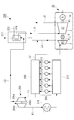
- each cylinder part 213 is connected to the air supply manifold 217, and the air supply manifold 217 is connected to the compressor part 205b of the exhaust turbo supercharger 205 via the air supply pipe K1.
- An air cooler (intercooler) 219 is installed in the air supply pipe K1.
- the power turbine 2 is rotationally driven by the exhaust gas extracted from the exhaust manifold 215 via the second exhaust pipe L2, and the steam turbine 3 is supplied with steam generated by the exhaust gas economizer 211. And is driven to rotate.
- the steam thus generated by the exhaust gas economizer 211 is introduced into the steam turbine 3 through the first steam pipe J1, and the steam that has finished work in the steam turbine 3 is discharged by the second steam pipe J2. It is led to a condenser (condenser) (not shown).
- the power turbine 2 and the steam turbine 3 are coupled in series, and the generator 14 is driven via the shaft 13.
- the output shaft 4 of the power turbine 2 is connected to the output shaft 6 of the steam turbine 9 through a clutch device 7 (SSS clutch).
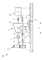
- FIG. 2 is a side view of the combined power generation apparatus 30 showing the first embodiment of the present invention
- FIG. 3 is a plan view of the same.
- the combined power generation apparatus 30 includes output shafts 4 and 5 to which rotation is transmitted from the power turbine 2 installed on the upper surface of the base portion 1 via the reduction gear 10.
- the output shaft 6 extending from the steam turbine 3 installed on the upper surface of the base portion 1 is connected by a clutch device 7 so that the generator 14 is driven by the combined output of the two types of turbines 2 and 3. It is configured.
- a coupling that can absorb expansion and contraction in the axial direction L is interposed on the shaft 13 that connects the steam turbine 3 and the generator 14.
- the rotational speed of the power turbine 2 is about 15000 to 25000 rpm, while the rotational speed of the steam turbine 3 is about 6000 to 12000 rpm, and there is a difference in the rotational speed between the turbines 2 and 3.
- the rotational speed of the output shaft 4 is decelerated, and the rotational speeds of the turbines 2 and 3 are made coincident (synchronized).
- the thermal expansion amount is larger in the steam turbine 3, and the thermal expansion amount along the axial direction L is several millimeters or more. It has been found that the amount of thermal expansion along the axial direction L of the power turbine 2 is relatively small, 1/2 to 1/5 or less of that of the steam turbine 3, and therefore the amount of thermal expansion of the output shaft 6 of the steam turbine 3 is absorbed. is important.
- the steam turbine 3 has one end in the axial direction L fixed to the upper surface of the base portion 1 as a thermal expansion starting point 11. As this thermal expansion starting point 11, a bearing support part on the clutch device 7 side of the steam turbine 3 can be exemplified.
- thermal expansion movement point 15 is a bearing support portion on the side opposite to the clutch device 7 of the steam turbine 3.
- This relative movement structure A has a structure in which the thermal expansion starting point 11 faces the clutch device 7 side of the steam turbine 3 and the thermal expansion movement point 15 faces the opposite side of the clutch device 7 of the steam turbine 3.
- the thermal expansion moving point 15 is fixed on the moving pedestal 17 via the support portion 16.
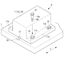
- the movable pedestal 17 is installed so as to be movable in the axial direction L with respect to the upper surface of the base portion 1. As shown in FIG. 4, the movable pedestal 17 has both side portions 17 a fastened to the upper surface of the base portion 1 by a plurality of stepped bolts 18, and is prevented from lifting from the upper surface of the base portion 1.
- the stepped bolt 18 is provided with a stepped portion 18a following the head.
- the outer diameter of the step portion 18a is larger than the outer diameter of the screw portion 18b, and the length of the step portion 18a is slightly longer than the thickness of both side portions 17a. For this reason, even if the stepped bolt 18 is fastened to the base portion 1, the fastening force is not applied to both side portions 17a.
- the bolt holes 17b drilled in both sides 17a are elongated holes along the axial direction L, and have an inner width through which the step 18a of the stepped bolt 18 can be inserted.
- the movable pedestal 17 can slide the upper surface of the base portion 1 in the axial direction L as much as the stepped portion 18a of the bolt 18 can be relatively moved in the bolt hole 17b.
- the expansion movement point 15 can be moved in the axial direction L.
- a bolt provided with a cylindrical spacer having the same length as the stepped portion 18a may be used.
- the movable pedestal 17 can be moved in the axial direction L by a key groove 20 formed between the upper surface of the base portion 1 and extending along the axial direction L, and a key 21 fitted in the key groove 20. Guided to be.
- the key 21 may have a length close to the entire length of the moving base 17 in the L direction, or may be divided into a plurality of parts.
- the combined power generation device 30 configured as described above has the thermal expansion starting point 11 of the steam turbine 3 directed toward the clutch device 7 and fixed to the upper surface of the base portion 1, and the thermal expansion of the steam turbine 3.
- the moving point 15 is directed to the opposite side of the clutch device 7 and has a relative moving structure A fixed on a moving pedestal 17 installed so as to be movable only in the axial direction L with respect to the upper surface of the base portion 1. .
- the axial length between the steam turbine 3 and the clutch device 7 can be shortened, thereby causing misalignment. Therefore, the alignment accuracy of the combined power generation apparatus 30 can be significantly improved.
- the thermal expansion moving point 15 of the steam turbine 3 is fixed on the moving pedestal 17, while the generator 14 is fixed to the upper surface of the base portion 1.
- a coupling that can absorb the expansion and contraction in the axial direction L is interposed in the shaft 13 that connects to the power supply 14.
- the movable pedestal 17 is extended to the generator 14, and the generator 14 is moved to the movable pedestal 17. It is also possible to make a change such as omitting the expansion / contraction structure of the shaft 13 in a configuration in which the shaft 13 is placed thereon.
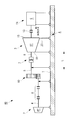
- FIG. 5 is a side view of a combined power generation apparatus showing a second embodiment of the present invention.
- this combined power generation device 40 the same components as those in the combined power generation device 30 of the first embodiment shown in FIG.
- the combined power generation device 40 of the second embodiment includes a relative movement structure A similar to that of the first embodiment. That is, the thermal expansion starting point 11 of the steam turbine 3 is directed to the clutch device 7 side, and the thermal expansion movement point 15 is directed to the opposite side of the clutch device 7.
- the thermal expansion moving point 15 of the steam turbine 3 is fixed on the moving pedestal 17 via the support portion 16, and moves along the axial direction L on the upper surface of the base portion 1.
- the thermal expansion movement point 15 of the steam turbine 3 is connected to the upper surface of the base portion 1 via the flexible support portion 23.
- the moving pedestal 17 is not provided.
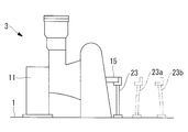
- the flexible support portion 23 allows the thermal expansion movement point 15 to move in the axial direction L by bending only in the axial direction L while connecting the thermal expansion movement point 15 to the upper surface of the base portion 1. It is. Specifically, as shown in FIGS. 6 and 7, the flexible support portion 23 is a plate-like member that is formed of, for example, a high-strength steel material and extends along a plane orthogonal to the axial direction L, and its lower end. The upper part is connected to the vicinity of the thermal expansion transfer point 15 of the steam turbine 3.
- the flexible support portion 23 supports the thermal expansion movement point 15 in a vertical posture as shown by a solid line in FIG. Further, when the steam turbine 3 thermally expands and the thermal expansion moving point 15 moves to the side opposite to the clutch device 7 along the axial direction L, the flexible support portion 23 is axially moved as indicated by reference numeral 23a in FIG. It bends along L and absorbs the movement of the thermal expansion movement point 15.
- the flexible support portion 23 can be formed very simply by a flexible plate material or the like, the construction cost of the combined power generation apparatus 40 can be further reduced and high reliability can be obtained.
- the flexible support portion 23 bends only in the axial direction L, there is no possibility that an error occurs in the alignment in the axial direction L due to the flexible support portion 23 being bent, and the alignment accuracy can be improved. it can.
- the shape of the flexible support portion 23 is bent toward the steam turbine 3 as indicated by reference numeral 23b in FIG. 6, and the steam turbine 3 is thermally expanded.
- the thermal expansion moving point 15 moves to the side opposite to the clutch device 7 along the axial direction L, the flexible support portion 23 may be deformed into a vertical posture.
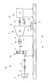
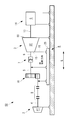
- FIG. 8 is a side view of a combined power generation apparatus showing a third embodiment of the present invention.
- This combined power generation device 50 includes a relative movement structure B different from the combined power generation devices 30 and 40 of the first and second embodiments.
- the positional relationship between the thermal expansion start point 11 and the thermal expansion movement point 15 of the steam turbine 3 along the axial direction L is the relative movement structure of the combined power generation devices 30 and 40 of the first and second embodiments. It is the opposite of A. That is, the thermal expansion moving point 15 is directed to the clutch device 7 side.
- a moving pedestal 25 is installed on the upper surface of the base portion 1 so as to be movable in the axial direction L.
- the moving pedestal 25 is longer in the axial direction L than the moving pedestal 17 (see FIG. 2) in the first embodiment, but is configured to be installed on the upper surface of the base portion 1 with stepped bolts 18. (Refer FIG. 4), the structure etc. which can be moved along the axial direction L using the keyway 20 and the key 21 with respect to the base part 1 are the same as that of 1st Embodiment.
- the thermal expansion starting point 11 of the steam turbine 3 is stationary with respect to the base portion 1, while the thermal expansion moving point. 15, the clutch device 7, the speed reduction device 10, and the like move together with the moving base 25 in the direction away from the steam turbine 3 along the axial direction L.
- This movement is absorbed by the flexible joint 8. For this reason, relative movement does not occur between the thermal expansion movement point 15 and the clutch device 7, and stress due to thermal expansion does not reach the clutch device 7.
- the combined power generation device 50 can be shortened in the axial direction, miniaturizing and improving alignment accuracy. And the construction cost can be reduced. Moreover, since the thermal expansion of the steam turbine 3 does not reach the shaft 13 connecting the steam turbine 3 and the generator 14, the extendable coupling as shown in FIG. 2 can be omitted.
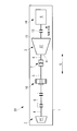
- FIG. 9 is a side view of a combined power generation apparatus showing a fourth embodiment of the present invention.
- the combined power generation device 60 has a longer dimension along the axial direction L of the moving base 26 than the moving base 25 of the third embodiment.
- the thermal expansion moving point 15 of the steam turbine 3, the clutch device 7, the power turbine 2 speed reducer 10, and the like are installed on the moving base 25, but in this fourth embodiment, the power turbine 2 and the flexible joint 8 are also installed on the upper surface of the movable base 26.
- Other configurations are the same as those of the third embodiment.
- the third embodiment there is no need to provide a flexible joint between the steam turbine 3 and the clutch device 7, and the combined power generation device 60 is shortened in the axial direction as compared with the conventional one, downsizing and improvement in alignment accuracy. And the construction cost can be reduced.
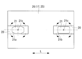
- the movable pedestal 26 may not slide smoothly on the foundation 1.
- the length of the key 21 is remarkably shorter than the dimension along the axial direction L of the movable pedestal 17, and the key 21 is rotated by a small angle inside the key groove 20.
- a rotation center 21c is provided, and a plurality of rotation centers 21c are arranged apart from each other in the axial direction L.
- each key 21 has chamfers 21 a or R chamfers 21 b at its four corners in plan view, and can be slightly rotated around the rotation center 21 c inside the key groove 20. it can.
- a plurality of such keys 21 are arranged along the axial direction L in the keyway 20. It is preferable to enclose a highly viscous liquid such as grease between the keyway 20 and the key 21.
- the key groove 20 may be formed over the entire length of the movable pedestal 17. However, as shown in FIG. 11, the short key groove 20 that can fit the key 21 is dispersed along the axial direction L. It may be formed.
- the base portion 1 can be smoothly slid. Further, even if the moving pedestal 26, the key groove 20, the key 21 and the like are thermally expanded due to the heat of the steam turbine 3, each key 21 rotates by a minute angle inside the key groove 20. The thermal deformation is absorbed. Therefore, the alignment accuracy of the combined cycle power generation device 60 can be improved with a simple structure.
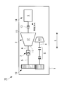
- FIG. 12 is a side view of a combined power generation apparatus showing a fifth embodiment of the present invention
- FIG. 13 is a plan view of the same.
- This combined power generator 70 is a modification of the combined power generator 30 of the first embodiment shown in FIG. That is, in the combined power generation device 30 of the first embodiment, the power turbine 2 and the steam turbine 3 are arranged in series. However, in this combined power generation device 70, the power turbine 2 and the steam turbine 3 are arranged in parallel. Is arranged. Since the other configuration is the same as that of the combined power generation apparatus 30 of the first embodiment, the same reference numerals are given to the respective parts and the description thereof is omitted.
- the thermal expansion in the axial direction L due to the thermal expansion of the steam turbine 3 is absorbed by the movement of the movable pedestal 17 similarly to the combined power generation apparatus 30 of the first embodiment. Therefore, it is not necessary to provide a flexible joint between the steam turbine 3 and the clutch device 7, thereby shortening the axial length between the steam turbine 3 and the clutch device 7. And combined with the power turbine 2 and the steam turbine 3 being arranged in parallel, the dimension along the axial direction L of the combined power generation apparatus 70 can be greatly reduced, and the alignment accuracy can be improved.
- the number of flexible joints is reduced by preventing the stress due to the thermal expansion of the turbine from reaching the clutch device, and the size and construction in the axial direction are mainly reduced. Cost reduction and improved alignment accuracy can be realized.
- the axial dimension of the combined power unit is shortened by mounting the combined power unit according to the present invention on the ship, the space occupancy rate inside the hull is small. As a result, the layout within the hull is improved, and the degree of freedom in designing each part can be increased.
Landscapes
- Engineering & Computer Science (AREA)
- Chemical & Material Sciences (AREA)
- Combustion & Propulsion (AREA)
- Mechanical Engineering (AREA)
- General Engineering & Computer Science (AREA)
- Ocean & Marine Engineering (AREA)
- Chemical Kinetics & Catalysis (AREA)
- General Chemical & Material Sciences (AREA)
- Engine Equipment That Uses Special Cycles (AREA)
Priority Applications (3)
| Application Number | Priority Date | Filing Date | Title |
|---|---|---|---|
| EP14839737.5A EP2921660A4 (en) | 2013-08-28 | 2014-08-22 | COMBINED POWER FORCE GENERATION APPARATUS AND SHIP COMPRISING THE SAME |
| KR1020157010691A KR101547451B1 (ko) | 2013-08-28 | 2014-08-22 | 콤바인드 동력 장치 및 이것을 탑재한 선박 |
| CN201480002748.3A CN105518259A (zh) | 2013-08-28 | 2014-08-22 | 混合动力装置及搭载它的船舶 |
Applications Claiming Priority (2)
| Application Number | Priority Date | Filing Date | Title |
|---|---|---|---|
| JP2013176580A JP2015045262A (ja) | 2013-08-28 | 2013-08-28 | コンバインド動力装置およびこれを搭載した船舶 |
| JP2013-176580 | 2013-08-28 |
Publications (1)
| Publication Number | Publication Date |
|---|---|
| WO2015029898A1 true WO2015029898A1 (ja) | 2015-03-05 |
Family
ID=52586457
Family Applications (1)
| Application Number | Title | Priority Date | Filing Date |
|---|---|---|---|
| PCT/JP2014/072000 Ceased WO2015029898A1 (ja) | 2013-08-28 | 2014-08-22 | コンバインド動力装置およびこれを搭載した船舶 |
Country Status (5)
| Country | Link |
|---|---|
| EP (1) | EP2921660A4 (enExample) |
| JP (1) | JP2015045262A (enExample) |
| KR (1) | KR101547451B1 (enExample) |
| CN (1) | CN105518259A (enExample) |
| WO (1) | WO2015029898A1 (enExample) |
Cited By (3)
| Publication number | Priority date | Publication date | Assignee | Title |
|---|---|---|---|---|
| WO2016184678A1 (en) * | 2015-05-15 | 2016-11-24 | General Electric Technology Gmbh | Steam turbine foundation |
| CN109204761A (zh) * | 2018-09-26 | 2019-01-15 | 中国船舶重工集团公司第七0三研究所 | 一种具有蒸汽排放功能的船用主机组模块化集成机架 |
| CN114607475A (zh) * | 2022-04-08 | 2022-06-10 | 哈尔滨汽轮机厂有限责任公司 | 一种5mw一体化布置汽轮发电机组 |
Families Citing this family (2)
| Publication number | Priority date | Publication date | Assignee | Title |
|---|---|---|---|---|
| CN109878675A (zh) * | 2019-02-28 | 2019-06-14 | 哈尔滨工程大学 | 一种双电机同轴式气电混合船舶动力系统 |
| US11460037B2 (en) | 2019-03-29 | 2022-10-04 | Pratt & Whitney Canada Corp. | Bearing housing |
Citations (3)
| Publication number | Priority date | Publication date | Assignee | Title |
|---|---|---|---|---|
| JPH06257411A (ja) | 1992-12-09 | 1994-09-13 | General Electric Co <Ge> | 発電システム |
| JP2004332722A (ja) * | 2003-05-10 | 2004-11-25 | Atlas Copco Energas Gmbh | ターボ機械 |
| JP2010133284A (ja) * | 2008-12-02 | 2010-06-17 | Mitsubishi Heavy Ind Ltd | 発電システム |
Family Cites Families (11)
| Publication number | Priority date | Publication date | Assignee | Title |
|---|---|---|---|---|
| JPS60178311U (ja) * | 1984-05-04 | 1985-11-27 | 株式会社日立製作所 | コンバインドプラント |
| JP2672649B2 (ja) * | 1989-06-05 | 1997-11-05 | 株式会社東芝 | 一軸型コンバインドサイクルにおける蒸気タービン |
| US4961310A (en) * | 1989-07-03 | 1990-10-09 | General Electric Company | Single shaft combined cycle turbine |
| FR2702243B1 (fr) * | 1993-03-03 | 1995-04-14 | Gec Alsthom Electromec | Centrale de production d'énergie à turbine à gaz et turbine à vapeur. |
| FR2719627B1 (fr) * | 1994-05-03 | 1996-06-14 | Gec Alsthom Electromec | Unité de production d'énergie électrique à cycle combiné comportant une turbine à gaz et une turbine à vapeur à plusieurs modules. |
| JP2002349289A (ja) * | 2001-05-21 | 2002-12-04 | Toshiba Corp | タービン用ソールプレートおよびそれを用いた発電プラント機器 |
| US7267319B2 (en) * | 2004-11-09 | 2007-09-11 | General Electric Company | Low-friction slide-plates for rotary machines |
| EP1764485A1 (de) * | 2005-09-15 | 2007-03-21 | Siemens Aktiengesellschaft | Vorrichtung zur Lagerung der Rotationsmaschinen einer stationären Turbogruppe |
| JP5047130B2 (ja) * | 2008-11-18 | 2012-10-10 | 三菱重工業株式会社 | タービンケーシングの支持構造 |
| JP5079102B2 (ja) * | 2008-12-26 | 2012-11-21 | 三菱重工業株式会社 | 排熱回収システムの制御装置 |
| CN102926873A (zh) * | 2012-11-28 | 2013-02-13 | 北京华清燃气轮机与煤气化联合循环工程技术有限公司 | 一种燃气轮机支撑系统 |
-
2013
- 2013-08-28 JP JP2013176580A patent/JP2015045262A/ja active Pending
-
2014
- 2014-08-22 KR KR1020157010691A patent/KR101547451B1/ko not_active Expired - Fee Related
- 2014-08-22 WO PCT/JP2014/072000 patent/WO2015029898A1/ja not_active Ceased
- 2014-08-22 EP EP14839737.5A patent/EP2921660A4/en not_active Withdrawn
- 2014-08-22 CN CN201480002748.3A patent/CN105518259A/zh active Pending
Patent Citations (3)
| Publication number | Priority date | Publication date | Assignee | Title |
|---|---|---|---|---|
| JPH06257411A (ja) | 1992-12-09 | 1994-09-13 | General Electric Co <Ge> | 発電システム |
| JP2004332722A (ja) * | 2003-05-10 | 2004-11-25 | Atlas Copco Energas Gmbh | ターボ機械 |
| JP2010133284A (ja) * | 2008-12-02 | 2010-06-17 | Mitsubishi Heavy Ind Ltd | 発電システム |
Non-Patent Citations (1)
| Title |
|---|
| See also references of EP2921660A4 * |
Cited By (3)
| Publication number | Priority date | Publication date | Assignee | Title |
|---|---|---|---|---|
| WO2016184678A1 (en) * | 2015-05-15 | 2016-11-24 | General Electric Technology Gmbh | Steam turbine foundation |
| CN109204761A (zh) * | 2018-09-26 | 2019-01-15 | 中国船舶重工集团公司第七0三研究所 | 一种具有蒸汽排放功能的船用主机组模块化集成机架 |
| CN114607475A (zh) * | 2022-04-08 | 2022-06-10 | 哈尔滨汽轮机厂有限责任公司 | 一种5mw一体化布置汽轮发电机组 |
Also Published As
| Publication number | Publication date |
|---|---|
| KR20150059650A (ko) | 2015-06-01 |
| KR101547451B1 (ko) | 2015-08-25 |
| JP2015045262A (ja) | 2015-03-12 |
| CN105518259A (zh) | 2016-04-20 |
| EP2921660A1 (en) | 2015-09-23 |
| EP2921660A4 (en) | 2015-12-23 |
Similar Documents
| Publication | Publication Date | Title |
|---|---|---|
| WO2015029898A1 (ja) | コンバインド動力装置およびこれを搭載した船舶 | |
| JP5631660B2 (ja) | タービンシステム | |
| EP3002433B1 (en) | Geared architecture for a gas turbine | |
| JP5596109B2 (ja) | ガスタービンエンジン | |
| EP2935840B1 (en) | Mount with an axial upstream linkage for connecting a gearbox to a turbine engine case | |
| US10982713B2 (en) | Closed cycle heat engine | |
| US20190316846A1 (en) | Waste heat recovery and conversion system and related methods | |
| CN114076036B (zh) | 空气涡轮启动器 | |
| EP3080405B1 (en) | Gas turbine offshore installations | |
| CN102869853A (zh) | 制造微型燃气轮机的方法 | |
| US10364038B2 (en) | Propulsion unit for an aircraft | |
| JP2015052345A (ja) | フォイル軸受ユニット | |
| JP6000077B2 (ja) | 排気タービンの支持構造 | |
| US9657596B2 (en) | Turbine housing assembly for a turbocharger | |
| CN106414945B (zh) | 涡轮复合单元 | |
| CN205674866U (zh) | 汽车辅助动力系统及新能源汽车 | |
| CN116399596A (zh) | 一种双向输出燃气轮机试验台 | |
| JP5667115B2 (ja) | ガスタービン及びガスタービン発電設備 | |
| JP2011080453A (ja) | 締結部材及び過給機 | |
| US10871084B2 (en) | Mount assembly | |
| JP2011208622A (ja) | 内燃機関の余剰排気エネルギ回収装置 | |
| Brun et al. | A novel centrifugal flow gas turbine design | |
| US11603890B2 (en) | Driveline engagement system | |
| JPH0574518B2 (enExample) | ||
| WO2018150770A1 (ja) | 吸気冷却システムおよび圧力伝達装置 |
Legal Events
| Date | Code | Title | Description |
|---|---|---|---|
| 121 | Ep: the epo has been informed by wipo that ep was designated in this application |
Ref document number: 14839737 Country of ref document: EP Kind code of ref document: A1 |
|
| ENP | Entry into the national phase |
Ref document number: 20157010691 Country of ref document: KR Kind code of ref document: A |
|
| REEP | Request for entry into the european phase |
Ref document number: 2014839737 Country of ref document: EP |
|
| WWE | Wipo information: entry into national phase |
Ref document number: 2014839737 Country of ref document: EP |
|
| NENP | Non-entry into the national phase |
Ref country code: DE |