WO2015029691A1 - Biochip support member, method for manufacturing biochip support member, biochip package, screening device, and screening method - Google Patents

Biochip support member, method for manufacturing biochip support member, biochip package, screening device, and screening method Download PDF

Info

Publication number
WO2015029691A1
WO2015029691A1 PCT/JP2014/070230 JP2014070230W WO2015029691A1 WO 2015029691 A1 WO2015029691 A1 WO 2015029691A1 JP 2014070230 W JP2014070230 W JP 2014070230W WO 2015029691 A1 WO2015029691 A1 WO 2015029691A1
Authority
WO
WIPO (PCT)
Prior art keywords
biochip
columnar
base material
support member
columnar member
Prior art date
Application number
PCT/JP2014/070230
Other languages
French (fr)
Japanese (ja)
Inventor
忠夫 伊佐見
林 豊
上田 武彦
Original Assignee
株式会社ニコン
Priority date (The priority date is an assumption and is not a legal conclusion. Google has not performed a legal analysis and makes no representation as to the accuracy of the date listed.)
Filing date
Publication date
Application filed by 株式会社ニコン filed Critical 株式会社ニコン
Priority to EP14840291.0A priority Critical patent/EP3040723A4/en
Priority to JP2015534105A priority patent/JPWO2015029691A1/en
Publication of WO2015029691A1 publication Critical patent/WO2015029691A1/en
Priority to US15/053,587 priority patent/US20160193608A1/en

Links

Images

Classifications

    • BPERFORMING OPERATIONS; TRANSPORTING
    • B01PHYSICAL OR CHEMICAL PROCESSES OR APPARATUS IN GENERAL
    • B01LCHEMICAL OR PHYSICAL LABORATORY APPARATUS FOR GENERAL USE
    • B01L9/00Supporting devices; Holding devices
    • B01L9/52Supports specially adapted for flat sample carriers, e.g. for plates, slides, chips
    • BPERFORMING OPERATIONS; TRANSPORTING
    • B01PHYSICAL OR CHEMICAL PROCESSES OR APPARATUS IN GENERAL
    • B01LCHEMICAL OR PHYSICAL LABORATORY APPARATUS FOR GENERAL USE
    • B01L3/00Containers or dishes for laboratory use, e.g. laboratory glassware; Droppers
    • B01L3/50Containers for the purpose of retaining a material to be analysed, e.g. test tubes
    • B01L3/508Containers for the purpose of retaining a material to be analysed, e.g. test tubes rigid containers not provided for above
    • B01L3/5085Containers for the purpose of retaining a material to be analysed, e.g. test tubes rigid containers not provided for above for multiple samples, e.g. microtitration plates
    • B01L3/50853Containers for the purpose of retaining a material to be analysed, e.g. test tubes rigid containers not provided for above for multiple samples, e.g. microtitration plates with covers or lids
    • BPERFORMING OPERATIONS; TRANSPORTING
    • B23MACHINE TOOLS; METAL-WORKING NOT OTHERWISE PROVIDED FOR
    • B23KSOLDERING OR UNSOLDERING; WELDING; CLADDING OR PLATING BY SOLDERING OR WELDING; CUTTING BY APPLYING HEAT LOCALLY, e.g. FLAME CUTTING; WORKING BY LASER BEAM
    • B23K20/00Non-electric welding by applying impact or other pressure, with or without the application of heat, e.g. cladding or plating
    • B23K20/10Non-electric welding by applying impact or other pressure, with or without the application of heat, e.g. cladding or plating making use of vibrations, e.g. ultrasonic welding
    • BPERFORMING OPERATIONS; TRANSPORTING
    • B29WORKING OF PLASTICS; WORKING OF SUBSTANCES IN A PLASTIC STATE IN GENERAL
    • B29CSHAPING OR JOINING OF PLASTICS; SHAPING OF MATERIAL IN A PLASTIC STATE, NOT OTHERWISE PROVIDED FOR; AFTER-TREATMENT OF THE SHAPED PRODUCTS, e.g. REPAIRING
    • B29C65/00Joining or sealing of preformed parts, e.g. welding of plastics materials; Apparatus therefor
    • B29C65/02Joining or sealing of preformed parts, e.g. welding of plastics materials; Apparatus therefor by heating, with or without pressure
    • B29C65/08Joining or sealing of preformed parts, e.g. welding of plastics materials; Apparatus therefor by heating, with or without pressure using ultrasonic vibrations
    • BPERFORMING OPERATIONS; TRANSPORTING
    • B29WORKING OF PLASTICS; WORKING OF SUBSTANCES IN A PLASTIC STATE IN GENERAL
    • B29CSHAPING OR JOINING OF PLASTICS; SHAPING OF MATERIAL IN A PLASTIC STATE, NOT OTHERWISE PROVIDED FOR; AFTER-TREATMENT OF THE SHAPED PRODUCTS, e.g. REPAIRING
    • B29C66/00General aspects of processes or apparatus for joining preformed parts
    • B29C66/01General aspects dealing with the joint area or with the area to be joined
    • B29C66/05Particular design of joint configurations
    • B29C66/10Particular design of joint configurations particular design of the joint cross-sections
    • B29C66/11Joint cross-sections comprising a single joint-segment, i.e. one of the parts to be joined comprising a single joint-segment in the joint cross-section
    • B29C66/112Single lapped joints
    • BPERFORMING OPERATIONS; TRANSPORTING
    • B29WORKING OF PLASTICS; WORKING OF SUBSTANCES IN A PLASTIC STATE IN GENERAL
    • B29CSHAPING OR JOINING OF PLASTICS; SHAPING OF MATERIAL IN A PLASTIC STATE, NOT OTHERWISE PROVIDED FOR; AFTER-TREATMENT OF THE SHAPED PRODUCTS, e.g. REPAIRING
    • B29C66/00General aspects of processes or apparatus for joining preformed parts
    • B29C66/01General aspects dealing with the joint area or with the area to be joined
    • B29C66/05Particular design of joint configurations
    • B29C66/10Particular design of joint configurations particular design of the joint cross-sections
    • B29C66/11Joint cross-sections comprising a single joint-segment, i.e. one of the parts to be joined comprising a single joint-segment in the joint cross-section
    • B29C66/114Single butt joints
    • BPERFORMING OPERATIONS; TRANSPORTING
    • B29WORKING OF PLASTICS; WORKING OF SUBSTANCES IN A PLASTIC STATE IN GENERAL
    • B29CSHAPING OR JOINING OF PLASTICS; SHAPING OF MATERIAL IN A PLASTIC STATE, NOT OTHERWISE PROVIDED FOR; AFTER-TREATMENT OF THE SHAPED PRODUCTS, e.g. REPAIRING
    • B29C66/00General aspects of processes or apparatus for joining preformed parts
    • B29C66/01General aspects dealing with the joint area or with the area to be joined
    • B29C66/05Particular design of joint configurations
    • B29C66/20Particular design of joint configurations particular design of the joint lines, e.g. of the weld lines
    • B29C66/24Particular design of joint configurations particular design of the joint lines, e.g. of the weld lines said joint lines being closed or non-straight
    • B29C66/242Particular design of joint configurations particular design of the joint lines, e.g. of the weld lines said joint lines being closed or non-straight said joint lines being closed, i.e. forming closed contours
    • B29C66/2422Particular design of joint configurations particular design of the joint lines, e.g. of the weld lines said joint lines being closed or non-straight said joint lines being closed, i.e. forming closed contours being circular, oval or elliptical
    • B29C66/24221Particular design of joint configurations particular design of the joint lines, e.g. of the weld lines said joint lines being closed or non-straight said joint lines being closed, i.e. forming closed contours being circular, oval or elliptical being circular
    • BPERFORMING OPERATIONS; TRANSPORTING
    • B29WORKING OF PLASTICS; WORKING OF SUBSTANCES IN A PLASTIC STATE IN GENERAL
    • B29CSHAPING OR JOINING OF PLASTICS; SHAPING OF MATERIAL IN A PLASTIC STATE, NOT OTHERWISE PROVIDED FOR; AFTER-TREATMENT OF THE SHAPED PRODUCTS, e.g. REPAIRING
    • B29C66/00General aspects of processes or apparatus for joining preformed parts
    • B29C66/01General aspects dealing with the joint area or with the area to be joined
    • B29C66/05Particular design of joint configurations
    • B29C66/302Particular design of joint configurations the area to be joined comprising melt initiators
    • B29C66/3022Particular design of joint configurations the area to be joined comprising melt initiators said melt initiators being integral with at least one of the parts to be joined
    • B29C66/30223Particular design of joint configurations the area to be joined comprising melt initiators said melt initiators being integral with at least one of the parts to be joined said melt initiators being rib-like
    • BPERFORMING OPERATIONS; TRANSPORTING
    • B29WORKING OF PLASTICS; WORKING OF SUBSTANCES IN A PLASTIC STATE IN GENERAL
    • B29CSHAPING OR JOINING OF PLASTICS; SHAPING OF MATERIAL IN A PLASTIC STATE, NOT OTHERWISE PROVIDED FOR; AFTER-TREATMENT OF THE SHAPED PRODUCTS, e.g. REPAIRING
    • B29C66/00General aspects of processes or apparatus for joining preformed parts
    • B29C66/40General aspects of joining substantially flat articles, e.g. plates, sheets or web-like materials; Making flat seams in tubular or hollow articles; Joining single elements to substantially flat surfaces
    • B29C66/47Joining single elements to sheets, plates or other substantially flat surfaces
    • B29C66/474Joining single elements to sheets, plates or other substantially flat surfaces said single elements being substantially non-flat
    • BPERFORMING OPERATIONS; TRANSPORTING
    • B29WORKING OF PLASTICS; WORKING OF SUBSTANCES IN A PLASTIC STATE IN GENERAL
    • B29CSHAPING OR JOINING OF PLASTICS; SHAPING OF MATERIAL IN A PLASTIC STATE, NOT OTHERWISE PROVIDED FOR; AFTER-TREATMENT OF THE SHAPED PRODUCTS, e.g. REPAIRING
    • B29C66/00General aspects of processes or apparatus for joining preformed parts
    • B29C66/50General aspects of joining tubular articles; General aspects of joining long products, i.e. bars or profiled elements; General aspects of joining single elements to tubular articles, hollow articles or bars; General aspects of joining several hollow-preforms to form hollow or tubular articles
    • B29C66/51Joining tubular articles, profiled elements or bars; Joining single elements to tubular articles, hollow articles or bars; Joining several hollow-preforms to form hollow or tubular articles
    • B29C66/53Joining single elements to tubular articles, hollow articles or bars
    • B29C66/534Joining single elements to open ends of tubular or hollow articles or to the ends of bars
    • B29C66/5346Joining single elements to open ends of tubular or hollow articles or to the ends of bars said single elements being substantially flat
    • BPERFORMING OPERATIONS; TRANSPORTING
    • B29WORKING OF PLASTICS; WORKING OF SUBSTANCES IN A PLASTIC STATE IN GENERAL
    • B29CSHAPING OR JOINING OF PLASTICS; SHAPING OF MATERIAL IN A PLASTIC STATE, NOT OTHERWISE PROVIDED FOR; AFTER-TREATMENT OF THE SHAPED PRODUCTS, e.g. REPAIRING
    • B29C66/00General aspects of processes or apparatus for joining preformed parts
    • B29C66/80General aspects of machine operations or constructions and parts thereof
    • B29C66/83General aspects of machine operations or constructions and parts thereof characterised by the movement of the joining or pressing tools
    • B29C66/832Reciprocating joining or pressing tools
    • B29C66/8322Joining or pressing tools reciprocating along one axis
    • BPERFORMING OPERATIONS; TRANSPORTING
    • B29WORKING OF PLASTICS; WORKING OF SUBSTANCES IN A PLASTIC STATE IN GENERAL
    • B29CSHAPING OR JOINING OF PLASTICS; SHAPING OF MATERIAL IN A PLASTIC STATE, NOT OTHERWISE PROVIDED FOR; AFTER-TREATMENT OF THE SHAPED PRODUCTS, e.g. REPAIRING
    • B29C66/00General aspects of processes or apparatus for joining preformed parts
    • B29C66/80General aspects of machine operations or constructions and parts thereof
    • B29C66/84Specific machine types or machines suitable for specific applications
    • B29C66/843Machines for making separate joints at the same time in different planes; Machines for making separate joints at the same time mounted in parallel or in series
    • B29C66/8432Machines for making separate joints at the same time mounted in parallel or in series
    • BPERFORMING OPERATIONS; TRANSPORTING
    • B81MICROSTRUCTURAL TECHNOLOGY
    • B81CPROCESSES OR APPARATUS SPECIALLY ADAPTED FOR THE MANUFACTURE OR TREATMENT OF MICROSTRUCTURAL DEVICES OR SYSTEMS
    • B81C3/00Assembling of devices or systems from individually processed components
    • B81C3/001Bonding of two components
    • GPHYSICS
    • G01MEASURING; TESTING
    • G01NINVESTIGATING OR ANALYSING MATERIALS BY DETERMINING THEIR CHEMICAL OR PHYSICAL PROPERTIES
    • G01N33/00Investigating or analysing materials by specific methods not covered by groups G01N1/00 - G01N31/00
    • G01N33/48Biological material, e.g. blood, urine; Haemocytometers
    • G01N33/50Chemical analysis of biological material, e.g. blood, urine; Testing involving biospecific ligand binding methods; Immunological testing
    • G01N33/53Immunoassay; Biospecific binding assay; Materials therefor
    • G01N33/543Immunoassay; Biospecific binding assay; Materials therefor with an insoluble carrier for immobilising immunochemicals
    • G01N33/54366Apparatus specially adapted for solid-phase testing
    • BPERFORMING OPERATIONS; TRANSPORTING
    • B01PHYSICAL OR CHEMICAL PROCESSES OR APPARATUS IN GENERAL
    • B01JCHEMICAL OR PHYSICAL PROCESSES, e.g. CATALYSIS OR COLLOID CHEMISTRY; THEIR RELEVANT APPARATUS
    • B01J2219/00Chemical, physical or physico-chemical processes in general; Their relevant apparatus
    • B01J2219/00274Sequential or parallel reactions; Apparatus and devices for combinatorial chemistry or for making arrays; Chemical library technology
    • B01J2219/00277Apparatus
    • B01J2219/00497Features relating to the solid phase supports
    • B01J2219/00504Pins
    • B01J2219/00509Microcolumns
    • BPERFORMING OPERATIONS; TRANSPORTING
    • B01PHYSICAL OR CHEMICAL PROCESSES OR APPARATUS IN GENERAL
    • B01JCHEMICAL OR PHYSICAL PROCESSES, e.g. CATALYSIS OR COLLOID CHEMISTRY; THEIR RELEVANT APPARATUS
    • B01J2219/00Chemical, physical or physico-chemical processes in general; Their relevant apparatus
    • B01J2219/00274Sequential or parallel reactions; Apparatus and devices for combinatorial chemistry or for making arrays; Chemical library technology
    • B01J2219/00277Apparatus
    • B01J2219/00497Features relating to the solid phase supports
    • B01J2219/00527Sheets
    • B01J2219/00529DNA chips
    • BPERFORMING OPERATIONS; TRANSPORTING
    • B01PHYSICAL OR CHEMICAL PROCESSES OR APPARATUS IN GENERAL
    • B01JCHEMICAL OR PHYSICAL PROCESSES, e.g. CATALYSIS OR COLLOID CHEMISTRY; THEIR RELEVANT APPARATUS
    • B01J2219/00Chemical, physical or physico-chemical processes in general; Their relevant apparatus
    • B01J2219/00274Sequential or parallel reactions; Apparatus and devices for combinatorial chemistry or for making arrays; Chemical library technology
    • B01J2219/00583Features relative to the processes being carried out
    • B01J2219/00603Making arrays on substantially continuous surfaces
    • B01J2219/00605Making arrays on substantially continuous surfaces the compounds being directly bound or immobilised to solid supports
    • B01J2219/00614Delimitation of the attachment areas
    • B01J2219/00621Delimitation of the attachment areas by physical means, e.g. trenches, raised areas
    • BPERFORMING OPERATIONS; TRANSPORTING
    • B01PHYSICAL OR CHEMICAL PROCESSES OR APPARATUS IN GENERAL
    • B01JCHEMICAL OR PHYSICAL PROCESSES, e.g. CATALYSIS OR COLLOID CHEMISTRY; THEIR RELEVANT APPARATUS
    • B01J2219/00Chemical, physical or physico-chemical processes in general; Their relevant apparatus
    • B01J2219/00274Sequential or parallel reactions; Apparatus and devices for combinatorial chemistry or for making arrays; Chemical library technology
    • B01J2219/00583Features relative to the processes being carried out
    • B01J2219/00603Making arrays on substantially continuous surfaces
    • B01J2219/00659Two-dimensional arrays
    • B01J2219/00662Two-dimensional arrays within two-dimensional arrays
    • BPERFORMING OPERATIONS; TRANSPORTING
    • B01PHYSICAL OR CHEMICAL PROCESSES OR APPARATUS IN GENERAL
    • B01LCHEMICAL OR PHYSICAL LABORATORY APPARATUS FOR GENERAL USE
    • B01L2200/00Solutions for specific problems relating to chemical or physical laboratory apparatus
    • B01L2200/02Adapting objects or devices to another
    • B01L2200/025Align devices or objects to ensure defined positions relative to each other
    • BPERFORMING OPERATIONS; TRANSPORTING
    • B01PHYSICAL OR CHEMICAL PROCESSES OR APPARATUS IN GENERAL
    • B01LCHEMICAL OR PHYSICAL LABORATORY APPARATUS FOR GENERAL USE
    • B01L2200/00Solutions for specific problems relating to chemical or physical laboratory apparatus
    • B01L2200/12Specific details about manufacturing devices
    • BPERFORMING OPERATIONS; TRANSPORTING
    • B01PHYSICAL OR CHEMICAL PROCESSES OR APPARATUS IN GENERAL
    • B01LCHEMICAL OR PHYSICAL LABORATORY APPARATUS FOR GENERAL USE
    • B01L2300/00Additional constructional details
    • B01L2300/06Auxiliary integrated devices, integrated components
    • B01L2300/0609Holders integrated in container to position an object
    • BPERFORMING OPERATIONS; TRANSPORTING
    • B01PHYSICAL OR CHEMICAL PROCESSES OR APPARATUS IN GENERAL
    • B01LCHEMICAL OR PHYSICAL LABORATORY APPARATUS FOR GENERAL USE
    • B01L2300/00Additional constructional details
    • B01L2300/06Auxiliary integrated devices, integrated components
    • B01L2300/0627Sensor or part of a sensor is integrated
    • B01L2300/0636Integrated biosensor, microarrays
    • BPERFORMING OPERATIONS; TRANSPORTING
    • B01PHYSICAL OR CHEMICAL PROCESSES OR APPARATUS IN GENERAL
    • B01LCHEMICAL OR PHYSICAL LABORATORY APPARATUS FOR GENERAL USE
    • B01L2300/00Additional constructional details
    • B01L2300/06Auxiliary integrated devices, integrated components
    • B01L2300/0627Sensor or part of a sensor is integrated
    • B01L2300/0654Lenses; Optical fibres
    • BPERFORMING OPERATIONS; TRANSPORTING
    • B01PHYSICAL OR CHEMICAL PROCESSES OR APPARATUS IN GENERAL
    • B01LCHEMICAL OR PHYSICAL LABORATORY APPARATUS FOR GENERAL USE
    • B01L2300/00Additional constructional details
    • B01L2300/08Geometry, shape and general structure
    • B01L2300/0809Geometry, shape and general structure rectangular shaped
    • B01L2300/0819Microarrays; Biochips
    • BPERFORMING OPERATIONS; TRANSPORTING
    • B01PHYSICAL OR CHEMICAL PROCESSES OR APPARATUS IN GENERAL
    • B01LCHEMICAL OR PHYSICAL LABORATORY APPARATUS FOR GENERAL USE
    • B01L2300/00Additional constructional details
    • B01L2300/08Geometry, shape and general structure
    • B01L2300/0848Specific forms of parts of containers
    • BPERFORMING OPERATIONS; TRANSPORTING
    • B29WORKING OF PLASTICS; WORKING OF SUBSTANCES IN A PLASTIC STATE IN GENERAL
    • B29CSHAPING OR JOINING OF PLASTICS; SHAPING OF MATERIAL IN A PLASTIC STATE, NOT OTHERWISE PROVIDED FOR; AFTER-TREATMENT OF THE SHAPED PRODUCTS, e.g. REPAIRING
    • B29C66/00General aspects of processes or apparatus for joining preformed parts
    • B29C66/70General aspects of processes or apparatus for joining preformed parts characterised by the composition, physical properties or the structure of the material of the parts to be joined; Joining with non-plastics material
    • B29C66/71General aspects of processes or apparatus for joining preformed parts characterised by the composition, physical properties or the structure of the material of the parts to be joined; Joining with non-plastics material characterised by the composition of the plastics material of the parts to be joined
    • BPERFORMING OPERATIONS; TRANSPORTING
    • B29WORKING OF PLASTICS; WORKING OF SUBSTANCES IN A PLASTIC STATE IN GENERAL
    • B29CSHAPING OR JOINING OF PLASTICS; SHAPING OF MATERIAL IN A PLASTIC STATE, NOT OTHERWISE PROVIDED FOR; AFTER-TREATMENT OF THE SHAPED PRODUCTS, e.g. REPAIRING
    • B29C66/00General aspects of processes or apparatus for joining preformed parts
    • B29C66/70General aspects of processes or apparatus for joining preformed parts characterised by the composition, physical properties or the structure of the material of the parts to be joined; Joining with non-plastics material
    • B29C66/73General aspects of processes or apparatus for joining preformed parts characterised by the composition, physical properties or the structure of the material of the parts to be joined; Joining with non-plastics material characterised by the intensive physical properties of the material of the parts to be joined, by the optical properties of the material of the parts to be joined, by the extensive physical properties of the parts to be joined, by the state of the material of the parts to be joined or by the material of the parts to be joined being a thermoplastic or a thermoset
    • B29C66/733General aspects of processes or apparatus for joining preformed parts characterised by the composition, physical properties or the structure of the material of the parts to be joined; Joining with non-plastics material characterised by the intensive physical properties of the material of the parts to be joined, by the optical properties of the material of the parts to be joined, by the extensive physical properties of the parts to be joined, by the state of the material of the parts to be joined or by the material of the parts to be joined being a thermoplastic or a thermoset characterised by the optical properties of the material of the parts to be joined, e.g. fluorescence, phosphorescence
    • B29C66/7336General aspects of processes or apparatus for joining preformed parts characterised by the composition, physical properties or the structure of the material of the parts to be joined; Joining with non-plastics material characterised by the intensive physical properties of the material of the parts to be joined, by the optical properties of the material of the parts to be joined, by the extensive physical properties of the parts to be joined, by the state of the material of the parts to be joined or by the material of the parts to be joined being a thermoplastic or a thermoset characterised by the optical properties of the material of the parts to be joined, e.g. fluorescence, phosphorescence at least one of the parts to be joined being opaque, transparent or translucent to visible light
    • B29C66/73365General aspects of processes or apparatus for joining preformed parts characterised by the composition, physical properties or the structure of the material of the parts to be joined; Joining with non-plastics material characterised by the intensive physical properties of the material of the parts to be joined, by the optical properties of the material of the parts to be joined, by the extensive physical properties of the parts to be joined, by the state of the material of the parts to be joined or by the material of the parts to be joined being a thermoplastic or a thermoset characterised by the optical properties of the material of the parts to be joined, e.g. fluorescence, phosphorescence at least one of the parts to be joined being opaque, transparent or translucent to visible light at least one of the parts to be joined being transparent or translucent to visible light
    • B29C66/73366General aspects of processes or apparatus for joining preformed parts characterised by the composition, physical properties or the structure of the material of the parts to be joined; Joining with non-plastics material characterised by the intensive physical properties of the material of the parts to be joined, by the optical properties of the material of the parts to be joined, by the extensive physical properties of the parts to be joined, by the state of the material of the parts to be joined or by the material of the parts to be joined being a thermoplastic or a thermoset characterised by the optical properties of the material of the parts to be joined, e.g. fluorescence, phosphorescence at least one of the parts to be joined being opaque, transparent or translucent to visible light at least one of the parts to be joined being transparent or translucent to visible light both parts to be joined being transparent or translucent to visible light
    • BPERFORMING OPERATIONS; TRANSPORTING
    • B29WORKING OF PLASTICS; WORKING OF SUBSTANCES IN A PLASTIC STATE IN GENERAL
    • B29CSHAPING OR JOINING OF PLASTICS; SHAPING OF MATERIAL IN A PLASTIC STATE, NOT OTHERWISE PROVIDED FOR; AFTER-TREATMENT OF THE SHAPED PRODUCTS, e.g. REPAIRING
    • B29C66/00General aspects of processes or apparatus for joining preformed parts
    • B29C66/70General aspects of processes or apparatus for joining preformed parts characterised by the composition, physical properties or the structure of the material of the parts to be joined; Joining with non-plastics material
    • B29C66/73General aspects of processes or apparatus for joining preformed parts characterised by the composition, physical properties or the structure of the material of the parts to be joined; Joining with non-plastics material characterised by the intensive physical properties of the material of the parts to be joined, by the optical properties of the material of the parts to be joined, by the extensive physical properties of the parts to be joined, by the state of the material of the parts to be joined or by the material of the parts to be joined being a thermoplastic or a thermoset
    • B29C66/739General aspects of processes or apparatus for joining preformed parts characterised by the composition, physical properties or the structure of the material of the parts to be joined; Joining with non-plastics material characterised by the intensive physical properties of the material of the parts to be joined, by the optical properties of the material of the parts to be joined, by the extensive physical properties of the parts to be joined, by the state of the material of the parts to be joined or by the material of the parts to be joined being a thermoplastic or a thermoset characterised by the material of the parts to be joined being a thermoplastic or a thermoset
    • B29C66/7392General aspects of processes or apparatus for joining preformed parts characterised by the composition, physical properties or the structure of the material of the parts to be joined; Joining with non-plastics material characterised by the intensive physical properties of the material of the parts to be joined, by the optical properties of the material of the parts to be joined, by the extensive physical properties of the parts to be joined, by the state of the material of the parts to be joined or by the material of the parts to be joined being a thermoplastic or a thermoset characterised by the material of the parts to be joined being a thermoplastic or a thermoset characterised by the material of at least one of the parts being a thermoplastic
    • B29C66/73921General aspects of processes or apparatus for joining preformed parts characterised by the composition, physical properties or the structure of the material of the parts to be joined; Joining with non-plastics material characterised by the intensive physical properties of the material of the parts to be joined, by the optical properties of the material of the parts to be joined, by the extensive physical properties of the parts to be joined, by the state of the material of the parts to be joined or by the material of the parts to be joined being a thermoplastic or a thermoset characterised by the material of the parts to be joined being a thermoplastic or a thermoset characterised by the material of at least one of the parts being a thermoplastic characterised by the materials of both parts being thermoplastics
    • BPERFORMING OPERATIONS; TRANSPORTING
    • B29WORKING OF PLASTICS; WORKING OF SUBSTANCES IN A PLASTIC STATE IN GENERAL
    • B29LINDEXING SCHEME ASSOCIATED WITH SUBCLASS B29C, RELATING TO PARTICULAR ARTICLES
    • B29L2031/00Other particular articles
    • B29L2031/756Microarticles, nanoarticles
    • BPERFORMING OPERATIONS; TRANSPORTING
    • B81MICROSTRUCTURAL TECHNOLOGY
    • B81BMICROSTRUCTURAL DEVICES OR SYSTEMS, e.g. MICROMECHANICAL DEVICES
    • B81B2201/00Specific applications of microelectromechanical systems
    • B81B2201/02Sensors
    • B81B2201/0214Biosensors; Chemical sensors
    • BPERFORMING OPERATIONS; TRANSPORTING
    • B81MICROSTRUCTURAL TECHNOLOGY
    • B81CPROCESSES OR APPARATUS SPECIALLY ADAPTED FOR THE MANUFACTURE OR TREATMENT OF MICROSTRUCTURAL DEVICES OR SYSTEMS
    • B81C2203/00Forming microstructural systems
    • B81C2203/03Bonding two components
    • B81C2203/033Thermal bonding
    • B81C2203/037Thermal bonding techniques not provided for in B81C2203/035 - B81C2203/036

Landscapes

  • Engineering & Computer Science (AREA)
  • Mechanical Engineering (AREA)
  • Health & Medical Sciences (AREA)
  • Chemical & Material Sciences (AREA)
  • Hematology (AREA)
  • Chemical Kinetics & Catalysis (AREA)
  • Clinical Laboratory Science (AREA)
  • General Health & Medical Sciences (AREA)
  • Analytical Chemistry (AREA)
  • Immunology (AREA)
  • Life Sciences & Earth Sciences (AREA)
  • Molecular Biology (AREA)
  • Biomedical Technology (AREA)
  • Urology & Nephrology (AREA)
  • Microelectronics & Electronic Packaging (AREA)
  • Cell Biology (AREA)
  • Microbiology (AREA)
  • Biotechnology (AREA)
  • Food Science & Technology (AREA)
  • Medicinal Chemistry (AREA)
  • Physics & Mathematics (AREA)
  • Biochemistry (AREA)
  • General Physics & Mathematics (AREA)
  • Pathology (AREA)
  • Apparatus Associated With Microorganisms And Enzymes (AREA)
  • Automatic Analysis And Handling Materials Therefor (AREA)
  • Pressure Welding/Diffusion-Bonding (AREA)
  • Measuring Or Testing Involving Enzymes Or Micro-Organisms (AREA)

Abstract

The present invention comprises: a substrate; and columnar members which are separate members from the substrate. At one end the columnar members comprise support regions that are capable of supporting biochips on which biomolecules are formed, and at the other end the columnar members are attached to the substrate with attachment sections therebetween.

Description

バイオチップ用支持部材、バイオチップ用支持部材の製造方法、バイオチップ用パッケージ、スクリーニング装置及びスクリーニング方法Biochip support member, biochip support member manufacturing method, biochip package, screening apparatus, and screening method
 本発明は、バイオチップ用支持部材、バイオチップ用支持部材の製造方法、バイオチップ用パッケージ、スクリーニング装置及びスクリーニング方法に関するものである。 The present invention relates to a biochip support member, a biochip support member manufacturing method, a biochip package, a screening apparatus, and a screening method.
 近年、新薬開発プロセス、医療診断等などの分野において、基体に生体分子(プローブ)が固定されたマイクロアレイ(バイオチップ)を用い、検体(ターゲット物質)が結合したときに生じる特異的な反応を検出して分子診断等を行う技術が進められている。特許文献1には、マイクロアレイを備えるプレートと、ウェルを形成するプレートとを接着剤等により接合するアレイプレートが開示されている。 In recent years, in the fields of new drug development process, medical diagnosis, etc., using a microarray (biochip) with a biomolecule (probe) immobilized on a substrate, a specific reaction that occurs when a specimen (target substance) binds is detected. Thus, techniques for performing molecular diagnosis and the like are being advanced. Patent Document 1 discloses an array plate in which a plate provided with a microarray and a plate forming a well are joined with an adhesive or the like.
特表2005-513457号公報JP 2005-513457 A
 しかしながら、上述したような従来技術には、以下のような問題が存在する。 However, the following problems exist in the conventional technology as described above.
 微小のバイオチップを高精度に蛍光検出する場合、検出装置とバイオチップとを可能な限り接近させることが好ましいが、バイオチップがウェル部の底部に配されることから検出装置と試料とを接近させることには限界がある。 When detecting a minute biochip with high accuracy, it is preferable to bring the detection device and the biochip as close as possible. However, since the biochip is placed at the bottom of the well, the detection device and the sample are close together. There is a limit to doing it.
 本発明は、バイオチップを簡便に測定可能とするバイオチップ用支持部材、バイオチップ用支持部材の製造方法、バイオチップ用パッケージ、スクリーニング装置及びスクリーニング方法を提供することを目的とする。 An object of the present invention is to provide a biochip support member, a biochip support member manufacturing method, a biochip package, a screening apparatus, and a screening method that can easily measure a biochip.
 本発明の第1の態様に従えば、基材と、基材とは別の部材であって、生体分子が形成されたバイオチップを支持可能な支持領域を一端側に備えるとともに他端側で取付部を介して基材に取り付けられた柱状部材と、を備えるバイオチップ用支持部材が提供される。 According to the first aspect of the present invention, a base material and a member different from the base material are provided on one end side with a support region capable of supporting a biochip on which a biomolecule is formed, and on the other end side. There is provided a biochip support member comprising a columnar member attached to a base material via an attachment portion.
 本発明の第2の態様に従えば、基材と、基材とは別の部材であって、生体分子が形成されたバイオチップを支持可能な支持領域を一端側に備える柱状部材と、基材と柱状部材の他端側との間に介装された溶着部と、を備えるバイオチップ用支持部材が提供される。 According to the second aspect of the present invention, a base member and a columnar member that is a member different from the base material and includes a support region on one end side that can support a biochip on which a biomolecule is formed; There is provided a biochip support member comprising a welded portion interposed between the material and the other end of the columnar member.
 本発明の第3の態様に従えば、本発明の第1の態様または第2の態様のバイオチップ用支持部材と、生体分子と特異的に反応可能な標的を含む検体を保持可能な保持部を備える保持部材と、を備えるバイオチップ用パッケージが提供される。 According to the third aspect of the present invention, the biochip support member according to the first aspect or the second aspect of the present invention and a holding unit capable of holding a specimen containing a target that can specifically react with a biomolecule. A biochip package comprising a holding member comprising:
 本発明の第4の態様に従えば、本発明の第3の態様のバイオチップ用パッケージにおける保持部に検体を分注する分注装置と、検体に含まれる標的と生体分子との親和性を検出する検出装置と、を備えるスクリーニング装置が提供される。 According to the fourth aspect of the present invention, the dispensing device that dispenses the specimen to the holding part in the biochip package of the third aspect of the present invention, and the affinity between the target and the biomolecule contained in the specimen. There is provided a screening device comprising a detection device for detection.
 本発明の第5の態様に従えば、基材を準備する第1工程と、基材とは別の部材であって、生体分子が形成されたバイオチップを支持可能な支持領域を一端側に備える柱状部材を準備する第2工程と、柱状部材の他端側を基材に取付部を介して取り付ける第3工程と、を含むバイオチップ用支持部材の製造方法が提供される。 According to the fifth aspect of the present invention, the first step of preparing the base material and a support region that is a member different from the base material and can support the biochip on which the biomolecules are formed on one end side. There is provided a method for manufacturing a biochip support member, comprising: a second step of preparing a columnar member provided; and a third step of attaching the other end of the columnar member to a substrate via an attachment portion.
 本発明の第6の態様に従えば、本発明の第5の態様のバイオチップ用支持部材の製造方法で製造されたバイオチップ用支持部材を準備することと、生体分子と特異的に反応可能な標的を含む検体を保持可能な保持部を備える保持部材を準備することと、柱状部材の支持領域にバイオチップを配置して固定することと、バイオチップが検体で浸るように保持部に検体を分注することと、標的と生体分子とを検体の分注された保持部内で反応させることと、反応後に、バイオチップ用支持部材と保持部材とを分離することと、分離したバイオチップ用支持部材において、標的と生体分子との親和性を検出すること、を含むスクリーニング方法が提供される。 According to the sixth aspect of the present invention, a biochip support member manufactured by the method for manufacturing a biochip support member according to the fifth aspect of the present invention is prepared, and can specifically react with a biomolecule. Preparing a holding member having a holding part capable of holding a specimen containing a target, arranging and fixing the biochip in the support region of the columnar member, and holding the specimen in the holding part so that the biochip is immersed in the specimen , Reacting the target and the biomolecule in the holding portion where the specimen is dispensed, separating the support member for the biochip and the holding member after the reaction, and for the separated biochip There is provided a screening method comprising detecting affinity between a target and a biomolecule in a support member.
 本発明では、バイオチップを簡便に測定可能とする。 In the present invention, the biochip can be easily measured.
実施形態に係るバイオチップ用支持部材CPの外観斜視図。The external appearance perspective view of support member CP for biochip which concerns on embodiment. 実施形態に係るバイオチップ用支持部材CPの(a)は平面図であり、柱状部材10側から見た図、(b)は(a)におけるAーA線視断面図、(c)は(a)におけるBーB線視断面図、(d)は平面図であり、基材BP側から見た図。(A) of support member CP for biochip which concerns on embodiment is a top view, The figure seen from the columnar member 10 side, (b) is AA sectional view taken on the line in (a), (c) is ( BB line sectional drawing in a), (d) is a top view, the figure seen from the base-material BP side. 実施形態に係る超音波溶着を説明する図。The figure explaining the ultrasonic welding which concerns on embodiment. 実施形態に係る超音波溶着を説明する図。The figure explaining the ultrasonic welding which concerns on embodiment. 第1実施形態に係るバイオチップ用支持部材の製造方法を示すフローチャート。The flowchart which shows the manufacturing method of the supporting member for biochips which concerns on 1st Embodiment. 第2実施形態に係るバイオチップ用支持部材の製造方法の手順を示す図。The figure which shows the procedure of the manufacturing method of the supporting member for biochips concerning 2nd Embodiment. 第2実施形態に係るバイオチップ用支持部材の製造方法の手順を示す図。The figure which shows the procedure of the manufacturing method of the supporting member for biochips concerning 2nd Embodiment. 第3実施形態に係るバイオチップ用支持部材の製造方法の手順を示す図。The figure which shows the procedure of the manufacturing method of the supporting member for biochips concerning 3rd Embodiment. 第3実施形態に係るバイオチップ用支持部材の製造方法の手順を示す図。The figure which shows the procedure of the manufacturing method of the supporting member for biochips concerning 3rd Embodiment. バイオチップが固着された実施形態に係るバイオチップ用支持部材の外観斜視図。The external appearance perspective view of the support member for biochips which concerns on embodiment to which the biochip was fixed. 実施形態に係るウェルプレートの平面図。The top view of the well plate which concerns on embodiment. 実施形態に係るバイオチップ用パッケージの断面図。Sectional drawing of the package for biochips which concerns on embodiment. 実施形態に係るスクリーニング装置SCの模式図。The schematic diagram of the screening apparatus SC which concerns on embodiment. 実施形態に係る測定装置の概略構成図。The schematic block diagram of the measuring apparatus which concerns on embodiment. 実施形態に係るスクリーニング方法の手順を示すフローチャート。The flowchart which shows the procedure of the screening method which concerns on embodiment. 別形態のバイオチップ用支持部材を示す平面図。The top view which shows the supporting member for biochips of another form. 別形態の柱状部材10、保持部25を示す平面図。The top view which shows the columnar member 10 and the holding | maintenance part 25 of another form.
 以下、本発明のバイオチップ用支持部材、バイオチップ用支持部材の製造方法、バイオチップ用パッケージ、スクリーニング装置及びスクリーニング方法の実施の形態を、図1ないし図17を参照して説明する。 Hereinafter, embodiments of a biochip support member, a biochip support member manufacturing method, a biochip package, a screening apparatus, and a screening method according to the present invention will be described with reference to FIGS.
 なお、以下の説明では、鉛直方向をZ軸方向とし、水平方向でバイオチップ用支持部材
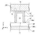
BPの長手方向(柱状部材10が6列に配列される方向)をY軸方向とし、Z軸方向及びY軸方向と直交する方向をX軸方向として説明する。X軸、Y軸及びZ軸は、直交座標系である。
In the following description, the vertical direction is the Z-axis direction, and the longitudinal direction of the biochip support member BP in the horizontal direction (the direction in which the columnar members 10 are arranged in six rows) is the Y-axis direction. The direction orthogonal to the Y-axis direction will be described as the X-axis direction. The X axis, the Y axis, and the Z axis are orthogonal coordinate systems.
 [バイオチップ用支持部材]
 まず、バイオチップ用支持部材について、図1乃至図4を参照して説明する。
[Support member for biochip]
First, the biochip support member will be described with reference to FIGS.
 図1は、バイオチップ用支持部材CPの外観斜視図である。図2(a)は、バイオチップ用支持部材CPの平面図であり、柱状部材10側から見た図である。図2(b)は、図2(a)におけるA-A線視断面図である。図2(c)は、図2(a)におけるB-B線視断面図である。図2(d)は、バイオチップ用支持部材CPの平面図であり、基材BP側から見た図である。 FIG. 1 is an external perspective view of the biochip support member CP. FIG. 2A is a plan view of the biochip support member CP, as viewed from the columnar member 10 side. FIG. 2B is a cross-sectional view taken along line AA in FIG. FIG. 2C is a cross-sectional view taken along line BB in FIG. FIG. 2D is a plan view of the biochip support member CP, as viewed from the base material BP side.
 バイオチップ用支持部材CPは、基材BPと、柱状部材10と、取付部JTとを備えている。基材BPは、例えば、平面視矩形の板状部材である。基材BPは、例えば樹脂で構成されている。一例として、基材BPは、熱可塑性の樹脂で構成されている。基材BPは、例えばキャスト製法により製造される。基材BPは、例えば透光性を有する部材である。一例として、基材BPは、透明な部材である。基材BPに用いる樹脂として、ポリメタクリル酸メチル樹脂(poly methyl methacrylate)等のアクリル樹脂(acrylic resin)、ポリカーボネート(polycarbonate(PC))、環状オレフィンコポリマー(cycloolefin copolymer(COC))、ポリスチレン(polystyrene(PS))等を例示することができる。 The biochip support member CP includes a base material BP, a columnar member 10, and a mounting portion JT. The base material BP is, for example, a plate member having a rectangular shape in plan view. The base material BP is made of, for example, a resin. As an example, the base material BP is made of a thermoplastic resin. The base material BP is manufactured by, for example, a cast manufacturing method. The base material BP is a member having translucency, for example. As an example, the base material BP is a transparent member. As a resin used for the base material BP, acrylic resin such as polymethyl methacrylate resin (acrylic resin), polycarbonate (polycarbonate (PC)), cyclic olefin copolymer (cycloolefin copolymer (COC)), polystyrene (polystyrene). PS)) and the like.
 基材BPの表面(第1面)BPaには、複数の柱状部材10がマトリクス状に配列されている。一例として、基材BPの表面(第1面)BPaには、複数の柱状部材10がX方向及びY方向に沿ってマトリクス状に配列されている。基板BPの表面BPaには、24個の柱状部材10が、基材BPの長手方向に6列、短手方向に4列で配列されている。基板BPの表面BPa及び裏面(第2面)BPbは、ラップ加工(鏡面加工)が施されている。 A plurality of columnar members 10 are arranged in a matrix on the surface (first surface) BPa of the base material BP. As an example, a plurality of columnar members 10 are arranged in a matrix along the X and Y directions on the surface (first surface) BPa of the base material BP. On the surface BPa of the substrate BP, 24 columnar members 10 are arranged in 6 rows in the longitudinal direction of the base material BP and 4 rows in the lateral direction. The front surface BPa and the back surface (second surface) BPb of the substrate BP are subjected to lapping (mirror surface processing).
 基材BPのY方向の両側には、ステージ上における当該基材BPのX、Y方向やθZ方向を位置合わせするための第1孔部(穴)AL1、第2孔部(長穴)AL2が位置合わせ部として形成されている。第1孔部AL1、第2孔部AL2は、互いに異なる形状であって、複数の柱状部材10と所定の相対位置関係を有するように形成されている。第1孔部AL1は、平面視円形の貫通孔で形成されている。第2孔部AL2は、例えば、第1孔部AL1とは異なる形状であって、Y方向(又はX方向)に延在する平面視長円(例、楕円)の貫通孔で形成されている。第1孔部AL1の中心と第2孔部AL2の中心とをとおる直線はY方向と平行となっている。第2孔部AL2の長円の短径側における幅は、第1孔部AL1の直径と同一に形成されている。 On both sides in the Y direction of the base material BP, a first hole (hole) AL1 and a second hole (long hole) AL2 for aligning the X, Y direction and θZ direction of the base material BP on the stage. Are formed as alignment portions. The first hole portion AL1 and the second hole portion AL2 have different shapes and are formed so as to have a predetermined relative positional relationship with the plurality of columnar members 10. The first hole AL1 is formed as a through hole having a circular shape in plan view. The second hole AL2 has a shape different from that of the first hole AL1, for example, and is formed by a through hole having an ellipse in a plan view (eg, an ellipse) extending in the Y direction (or X direction). . A straight line passing through the center of the first hole AL1 and the center of the second hole AL2 is parallel to the Y direction. The width of the ellipse of the second hole AL2 on the minor axis side is the same as the diameter of the first hole AL1.
 基材BPは、表面BPaの外縁と裏面BPbの外縁とに沿って形成された長手側の側面(第3面)BPcのそれぞれに把持部20を備えている。把持部20は、図2(c)に示すように、底部が断面V字状に形成されY方向に延在する複数の溝部21を備えている。溝部21はZ方向に沿って複数設けられている。把持部20は、各側面BPcにおけるY方向の中心から対称となる範囲に設けられている。把持部20の長さは、例えば、側面BPcの長さの1/2以上に設定される。 The base material BP includes a grip portion 20 on each of the side surfaces (third surface) BPc on the long side formed along the outer edge of the front surface BPa and the outer edge of the back surface BPb. As shown in FIG. 2 (c), the grip 20 includes a plurality of grooves 21 having a bottom formed in a V-shaped cross section and extending in the Y direction. A plurality of groove portions 21 are provided along the Z direction. The grip portion 20 is provided in a range that is symmetrical from the center in the Y direction on each side surface BPc. The length of the grip part 20 is set to, for example, ½ or more of the length of the side surface BPc.
 柱状部材10は、取付部JTを介して基材BPに取り付けられている。取付部JTは、柱状部材10の一部に形成されている。柱状部材10は、溶着により取付部JTを溶融させることにより、基材BPに取り付けられている。基材BPが透光性を有する部材で構成されている場合、図2(d)に示すように、溶着により取付部JTが溶融されることで生じた溶着部(溶着層)を、基材BPの裏面BPb側から観察することができる。溶着部(溶着層)の形状は、溶着により溶融される前の取付部JT(例えば後述する突起部13)の形状に応じた形状で現れる。 The columnar member 10 is attached to the base material BP via the attachment portion JT. The attachment portion JT is formed on a part of the columnar member 10. The columnar member 10 is attached to the base material BP by melting the attachment portion JT by welding. When the base material BP is composed of a light-transmitting member, as shown in FIG. 2 (d), the welding portion (welding layer) generated by melting the attachment portion JT by welding is used as the base material. It can be observed from the back side BPb side of the BP. The shape of the welded portion (welded layer) appears in a shape corresponding to the shape of the attachment portion JT (for example, a protrusion 13 described later) before being melted by welding.
 図3は、柱状部材10と、基材BPと、保持工具JG1と、超音波ホーンJG2とを示す。なお、図3は、溶着により基材BPに取り付けられる前(溶着前)の柱状部材10を示している。溶着前の柱状部材10は、円筒部11と、円筒部11の一端側(図2(b)及び図3では+Z側)に設けられた天板部12と、円筒部11の他端側(図3では-Z側)に設けられた突起部13とを備えている。 FIG. 3 shows the columnar member 10, the base material BP, the holding tool JG1, and the ultrasonic horn JG2. FIG. 3 shows the columnar member 10 before being attached to the base material BP by welding (before welding). The columnar member 10 before welding includes a cylindrical portion 11, a top plate portion 12 provided on one end side of the cylindrical portion 11 (+ Z side in FIGS. 2B and 3), and the other end side of the cylindrical portion 11 ( 3 is provided with a protrusion 13 provided on the −Z side in FIG.
 円筒部11は、一端側から他端側へ向かうにつれて漸次拡径する外周面と、一端側から
他端側へ向かうにつれて漸次拡径する内周面とを備えている。
The cylindrical portion 11 includes an outer peripheral surface that gradually increases in diameter from one end side to the other end side, and an inner peripheral surface that gradually increases in diameter from one end side to the other end side.
 天板部12は、バイオチップCPを支持可能な支持領域15を有している。図2(b)に示すように、天板部12は、一端側の表面にバイオチップBCを支持可能な支持領域15を備えている。 The top plate 12 has a support region 15 that can support the biochip CP. As shown in FIG. 2B, the top plate 12 includes a support region 15 that can support the biochip BC on the surface on one end side.
 柱状部材10は、マークFMを有している。マークFMは、基材BPにおける柱状部材10の位置を示す指標である。マークFMは、支持領域15に設けられている。一例として、マークFMは、支持領域15のうち、バイオチップBCが固着される領域以外の領域に設けられている。マークFMは、柱状部材10の中心を通りY方向に平行な直線上に設けられている。マークFMは、柱状部材10の中心より-Y側に設けられている。図2(a)では、マークFMは、複数の柱状部材10のうち、最も+Y側の列で最も+X側に位置する柱状部材10と、最も-Y側の列で最も+X側に位置する柱状部材10とに設けられている。すなわち、バイオチップ用支持部材CPは、マークFMを2つ有している。一例として、バイオチップ用支持部材CPにおいて、2つのマークFMは、最も+Y側の列で最も+X側に位置する柱状部材10(支持領域15)の中心と、最も-Y側の列で最も+X側に位置する柱状部材10(支持領域15)の中心とを通り、且つ、Y方向に平行な直線上に設けられている。なお、マークFMの数は、これに限るものではない。なお、複数のマークFMは、複数の柱状部材10それぞれの中心を通る直線状ではなく、複数の柱状部材10それぞれの中心を通る直線と平行な直線上に設けるようにしてもよい。マークFMは、例えば、円形、矩形、L字形、十字形等の形状を適宜選択可能である。マークFMは、例えば支持領域15に加工を施すことで設けられている。 The columnar member 10 has a mark FM. The mark FM is an index indicating the position of the columnar member 10 on the base material BP. The mark FM is provided in the support area 15. As an example, the mark FM is provided in a region other than the region to which the biochip BC is fixed in the support region 15. The mark FM is provided on a straight line passing through the center of the columnar member 10 and parallel to the Y direction. The mark FM is provided on the −Y side from the center of the columnar member 10. In FIG. 2A, the mark FM is a columnar member 10 that is positioned on the most + X side in the most + Y side row and a columnar position that is located on the most + X side in the most -Y side row among the plurality of columnar members 10. It is provided with the member 10. That is, the biochip support member CP has two marks FM. As an example, in the biochip support member CP, the two marks FM are the center of the columnar member 10 (support region 15) located on the most + X side in the most + Y side row and the most + X on the most -Y side row. It is provided on a straight line passing through the center of the columnar member 10 (support region 15) located on the side and parallel to the Y direction. The number of marks FM is not limited to this. The plurality of marks FM may be provided on a straight line parallel to a straight line passing through the centers of the plurality of columnar members 10 instead of a straight line passing through the centers of the plurality of columnar members 10. For the mark FM, for example, a circular shape, a rectangular shape, an L shape, a cross shape, or the like can be selected as appropriate. The mark FM is provided, for example, by processing the support region 15.
 天板部12は、窪み部16を有している。窪み部16は、支持領域15から窪んでいる。窪み部16は、凹部形状を有している。窪み部16の表面は、例えば球面である。天板部12の表面における窪み部16の外径は、バイオチップBCの外径よりも小さく設定されている。すなわち、窪み部16は、支持領域15にバイオチップBCを固着させた際にバイオチップBCによって遮蔽されて露出しない大きさに設けられている。 The top plate portion 12 has a hollow portion 16. The recessed portion 16 is recessed from the support region 15. The hollow portion 16 has a concave shape. The surface of the recess 16 is, for example, a spherical surface. The outer diameter of the hollow portion 16 on the surface of the top plate portion 12 is set to be smaller than the outer diameter of the biochip BC. That is, the recess 16 is provided in a size that is not exposed by being blocked by the biochip BC when the biochip BC is fixed to the support region 15.
 図3に戻り、突起部13は、円筒部11の端面に突設されている。突起部13は、先端がエッジ形状となる断面V字形状を有し、円筒部11の端面にリング状(円環状)に設けられている。そのため、突起部13を基材BPの表面BPaに当接させた状態で圧力及び超音波振動を加える等の溶着処理を行うことにより(詳細は後述)、突起部13は、溶融し、図4に示すように、柱状部材10と基材BPとを固着させる取付部(溶着部)JTとなる。 Referring back to FIG. 3, the protruding portion 13 protrudes from the end surface of the cylindrical portion 11. The protrusion 13 has a V-shaped cross-section with an edge at the tip, and is provided on the end surface of the cylindrical portion 11 in a ring shape (annular shape). Therefore, by performing a welding process such as applying pressure and ultrasonic vibration while the protrusion 13 is in contact with the surface BPa of the base material BP (details will be described later), the protrusion 13 is melted. As shown in FIG. 4, the columnar member 10 and the base material BP are attached to each other (attachment portion (welded portion) JT).
 柱状部材10は、一端側が天板部12によって閉塞され、基材BPに取り付けられる他端側に開口部17を有している。柱状部材10は、円筒部11と天板部12とに囲まれ他端側が開口した凹部を有している。柱状部材10は、キャップ状に形成されている。柱状部材10は、円筒部11と天板部12とに囲まれ他端側が開口した凹部によって形成された内部空間14を有している。 The columnar member 10 has one end side closed by the top plate portion 12 and an opening 17 on the other end side attached to the base material BP. The columnar member 10 has a recess surrounded by the cylindrical portion 11 and the top plate portion 12 and having the other end opened. The columnar member 10 is formed in a cap shape. The columnar member 10 has an internal space 14 formed by a recess surrounded by the cylindrical portion 11 and the top plate portion 12 and having the other end opened.
 柱状部材10は、例えば樹脂で構成されている。一例として、柱状部材10は、熱可塑性の樹脂で構成されている。柱状部材10は、例えば射出成形により製造される。柱状部材10は、例えば透光性を有する部材である。一例として、柱状部材10は、透明な部材である。柱状部材10に用いる樹脂として、ポリメタクリル酸メチル樹脂(poly methyl methacrylate)等のアクリル樹脂(acrylic resin)、ポリカーボネート(polycarbonate(PC))、環状オレフィンコポリマー(cycloolefin copolymer(COC))、ポリスチレン(polystyrene(PS))等を例示することができる。 The columnar member 10 is made of, for example, resin. As an example, the columnar member 10 is made of a thermoplastic resin. The columnar member 10 is manufactured by, for example, injection molding. The columnar member 10 is a member having translucency, for example. As an example, the columnar member 10 is a transparent member. As a resin used for the columnar member 10, acrylic resin such as polymethyl methacrylate resin (acrylic resin), polycarbonate (polycarbonate (PC)), cyclic olefin copolymer (cycloolefin copolymer (COC)), polystyrene (polystyrene). PS)) and the like.
 柱状部材10を溶着によって基材BPに取り付ける(接合する)場合には、柱状部材10に用いる材料の融点と基材BPに用いる材料の融点とは同じであることが望ましく、この観点から柱状部材10と基材BPとは同じ材料で形成されることが好ましい。また、柱状部材10及び基材BPに異種の材料を用いる場合でも、柱状部材10に用いる材料の融点と基材BPに用いる材料の融点とは近いことが好ましい。このような場合の例としては、柱状部材10と基材BPとの一方にポリメタクリル酸メチル樹脂(poly methyl methacrylate)を用い、柱状部材10と基材BPとの他方にポリカーボネート(polycarbonate(PC))を用いる例が挙げられる。 When the columnar member 10 is attached (joined) to the base material BP by welding, it is desirable that the melting point of the material used for the columnar member 10 and the melting point of the material used for the base material BP be the same. 10 and the substrate BP are preferably formed of the same material. Even when different materials are used for the columnar member 10 and the base material BP, the melting point of the material used for the columnar member 10 is preferably close to the melting point of the material used for the base material BP. As an example of such a case, a polymethyl methacrylate resin (polymethyl methacrylate) is used for one of the columnar member 10 and the base material BP, and a polycarbonate (polycarbonate (PC)) is used for the other of the columnar member 10 and the base material BP. ) Is used.
 [バイオチップ用支持部材の製造方法(第1実施形態)]
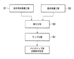
 次に、上述したバイオチップ用支持部材CPの製造方法の第1実施形態について、図5に示すフローチャートを参照して説明する。
[Method for Producing Biochip Support Member (First Embodiment)]
Next, a first embodiment of the method for manufacturing the biochip support member CP described above will be described with reference to the flowchart shown in FIG.
 図5に示すように、バイオチップ用支持部材CPの製造方法は、柱状部材準備工程(第2工程)S1、基材準備工程(第1工程)S2、取付工程(第3工程)S3、ラップ工程(第4工程)S4を含む。 As shown in FIG. 5, the manufacturing method of the biochip support member CP includes a columnar member preparation step (second step) S1, a substrate preparation step (first step) S2, an attachment step (third step) S3, and a wrap. Process (4th process) S4 is included.
 柱状部材準備工程S1においては、図3に示した溶着前の柱状部材10を準備する。例えば、金型を用いた射出成形によって柱状部材10を製造する場合には、円筒部11の他端側の端面位置をパーティングライン(型開閉位置)とし、円筒部11の外周面、支持領域15、及び窪み部16を含めた天板部12を固定型で形成し、円筒部11の他端側の端面、内部空間14及び突起部13を可動型で形成する。この場合、固定型においては、窪み部16にゲート(溶融樹脂注入口)を設けることにより、ゲート切断跡の突部が柱状部材10に残っても当該突部が支持領域15よりも突出することを防止できる。 In the columnar member preparation step S1, the columnar member 10 before welding shown in FIG. 3 is prepared. For example, when the columnar member 10 is manufactured by injection molding using a mold, the end surface position on the other end side of the cylindrical portion 11 is a parting line (die opening / closing position), and the outer peripheral surface of the cylindrical portion 11 and the support region 15 and the top plate part 12 including the hollow part 16 are formed by a fixed mold, and the end face on the other end side of the cylindrical part 11, the internal space 14 and the protrusion 13 are formed by a movable mold. In this case, in the fixed mold, by providing a gate (molten resin injection port) in the recess 16, the protrusion protrudes beyond the support region 15 even if the protrusion of the gate cut trace remains in the columnar member 10. Can be prevented.
 また、マークFMを備える柱状部材10については、例えば、マーク形状に対応する突部を金型に形成し、上記射出成形によりマークFMを形成することが好ましい。 Further, for the columnar member 10 provided with the mark FM, for example, it is preferable that a protrusion corresponding to the mark shape is formed on the mold and the mark FM is formed by the injection molding.
 基材準備工程S2においては、例えば、キャスト製法等によって製造された基材BPを準備する。基材準備工程S2では、把持部20、第1孔部AL1及び第2孔部AL2を基材BPに形成する。また、基材準備工程S2においては、基材BPの裏面BPbをラップ加工(例えば、ダイヤモンドラップ)を施す。 In the base material preparation step S2, for example, a base material BP manufactured by a casting method or the like is prepared. In the base material preparation step S2, the grip portion 20, the first hole portion AL1, and the second hole portion AL2 are formed on the base material BP. In the base material preparation step S2, the back surface BPb of the base material BP is lapped (for example, diamond wrap).
 基材BPと、基材BPとは別部材(別体)で形成された柱状部材10の準備がそれぞれ完了したら、柱状部材10と基材BPとを取り付ける取付工程S3を実施する。 When the preparation of the columnar member 10 formed of a separate member (separate member) from the substrate BP and the substrate BP is completed, an attachment step S3 for attaching the columnar member 10 and the substrate BP is performed.
 取付工程S3においては、図3に示すように、保持工具JG1及び超音波ホーン(振動子)JG2とを用いて溶着処理を実施する。保持工具JG1は、基材BPの裏面BPbを支持するものである。超音波ホーンJG2は、溶着対象物に対して超音波振動及び圧力を付与するものである。 In the attachment step S3, as shown in FIG. 3, a welding process is performed using a holding tool JG1 and an ultrasonic horn (vibrator) JG2. The holding tool JG1 supports the back surface BPb of the base material BP. The ultrasonic horn JG2 applies ultrasonic vibration and pressure to the object to be welded.
 まず、裏面BPbが当接するように基材BPを保持工具JG1上に載置する。次に、基材BPの表面BPa上の所定位置に柱状部材10を載置する。柱状部材10の載置は、例えば、負圧吸着保持が可能な搬送装置(不図示)等により柱状部材10の支持領域15を吸着保持して基材BPの所定位置に搬送する。柱状部材10に対して溶着処理を個々に実施する場合は引き続いて超音波ホーンJG2を支持領域15に当接させる。複数(ここでは24個)の柱状部材10に対して溶着処理を一括的に実施する場合は、全ての柱状部材10を基材BP上に載置した後に超音波ホーンJG2を支持領域15に当接させる。 First, the base material BP is placed on the holding tool JG1 so that the back surface BPb contacts. Next, the columnar member 10 is placed at a predetermined position on the surface BPa of the base material BP. The columnar member 10 is placed, for example, by sucking and holding the support region 15 of the columnar member 10 by a transporting device (not shown) capable of sucking and holding negative pressure and transporting it to a predetermined position of the substrate BP. When the welding process is individually performed on the columnar member 10, the ultrasonic horn JG 2 is subsequently brought into contact with the support region 15. When performing the welding process collectively on a plurality (24 in this case) of the columnar members 10, after placing all the columnar members 10 on the substrate BP, the ultrasonic horn JG 2 is applied to the support region 15. Make contact.
 なお、柱状部材10を基材BP上に搬送する方法についても、一個ずつ搬送する方法、複数個を一括的に搬送する方法を適宜採用可能である。柱状部材10の射出成形と連続して溶着処理を実施する場合には、例えば、金型におけるキャビティの配置を基材BPにおける柱状部材10の配置と同一とし、金型から離型した柱状部材10の全てを搬送装置が一括的に受け取って吸着保持し、保持した全ての柱状部材10を一括的に基材BP上に載置することも可能である。 In addition, also about the method of conveying the columnar member 10 on the base material BP, the method of conveying one by one and the method of conveying several collectively can be employ | adopted suitably. When the welding process is performed continuously with the injection molding of the columnar member 10, for example, the arrangement of the cavities in the mold is the same as the arrangement of the columnar members 10 in the base material BP, and the columnar member 10 released from the mold is used. It is also possible for the transfer device to receive all of the above in a collective manner and hold them by suction, and to place all the held columnar members 10 on the base material BP in a collective manner.
 基材BP上に柱状部材10が載置されると、柱状部材10の上部に超音波ホーンJG2を載置した後に、超音波ホーンJG2によって柱状部材10に超音波振動及び圧力を付与する。これにより、柱状部材10の突起部13と基材BPとの間に摩擦熱が発生し、主として応力が集中しやすい突起部13は溶融した後に固化(硬化)し、図4に示すように、取付部(溶着部、溶着層)JTとして柱状部材10と基材BPとを固着(結合)させる。このとき、柱状部材10は、内部空間14の開口部17が基材BPで閉塞されるため、内部に閉空間を形成することになる。開口部17と溶着部と基材BPとによって柱状部材10の内部に閉空間が形成される。 When the columnar member 10 is placed on the base material BP, the ultrasonic horn JG2 is placed on the columnar member 10, and then ultrasonic vibration and pressure are applied to the columnar member 10 by the ultrasonic horn JG2. As a result, frictional heat is generated between the protrusions 13 of the columnar member 10 and the base material BP, and the protrusions 13 on which stress is likely to concentrate are solidified (cured) after melting, as shown in FIG. The columnar member 10 and the base material BP are fixed (bonded) as the attachment portion (welded portion, welded layer) JT. At this time, since the opening 17 of the internal space 14 is closed by the base material BP, the columnar member 10 forms a closed space inside. A closed space is formed inside the columnar member 10 by the opening 17, the welded portion, and the base material BP.
 柱状部材10が取付部JTを介して基材BPに取り付けられると、ラップ工程S4に移行する。ラップ工程S4においては、ラップ加工された基材BPの裏面BPbを基準面として、柱状部材10の支持領域15をラップ加工(例えば、ダイヤモンドラップ)を施す。これにより、後工程の測定時に支持面となる裏面PBbを基準面としてバイオチップBCの支持面となる支持領域15が平坦化及び平滑化される。複数の柱状部材10が基材BPに取り付けられている場合には、全ての柱状部材10に対してラップ加工が行われる。このようにして、柱状部材10が取付部JTを介して基材BPに取り付けられ、支持面となる裏面BPb及び支持領域15が平坦化及び平滑化されたバイオチップ用支持部材CPが完成する。 When the columnar member 10 is attached to the base material BP via the attachment portion JT, the process proceeds to the lapping step S4. In the lapping step S4, lapping (for example, diamond lapping) is performed on the support region 15 of the columnar member 10 using the back surface BPb of the lapped base material BP as a reference surface. As a result, the support region 15 that becomes the support surface of the biochip BC is flattened and smoothed using the back surface PBb that becomes the support surface at the time of the measurement in the subsequent process as a reference surface. When the plurality of columnar members 10 are attached to the base material BP, lapping is performed on all the columnar members 10. In this way, the columnar member 10 is attached to the base material BP via the attachment portion JT, and the biochip support member CP in which the back surface BPb serving as the support surface and the support region 15 are flattened and smoothed is completed.
 以上説明したように、本実施形態では、バイオチップを簡便に測定可能とする。柱状部材10の先端に支持領域15を設けたので、支持領域15に固着されたバイオチップBCの周辺(バイオチップBCにおける生体分子形成側(支持領域15に固着する側の裏側))にはバイオチップ用支持部材CPを構成する部材が存在しない。そのため、測定装置はバイオチップBCに可能な限り接近した状態での測定が可能となり、バイオチップBCを高精度に測定することができる。また、本実施形態では、基材BPと柱状部材10を取付部JTを介して取り付けるため、基材BP及び柱状部材10を一体成形した場合に生じる虞がある反り等の変形に起因する悪影響を抑制することができる。例えば、基材BP及び柱状部材10を一体成形した場合には、温度分布や離型抵抗等によって基材BPに反り等の変形が生じる虞がある。この場合、複数の柱状部材10における支持領域15が同一高さ(同一のZ位置)とならないため、各柱状部材10に固着されたバイオチップBCを測定装置が測定する際に、バイオチップBC毎に焦点合わせが必要となりスループットが低下する虞がある。これに対して、本実施形態では、基材BPと柱状部材10を取付部JTを介して取り付ける構成を採ることにより、一体成形に起因して生じる支持領域15の高さのばらつきを抑えることが可能になる。そのため、支持領域15に固着されたバイオチップBCを測定する際の焦点合わせに要する時間を抑えることができ、スループットの低下を抑制できる。複数回焦点合わせを行った場合に生じる焦点合わせ誤差の影響を排除できる。高スループットで高精度にバイオチップBCを測定することができる。また、本実施形態では、基材BPの裏面BPbと支持領域15とをラップ加工して平坦化及び平滑化させるため、溶着時に取付部JTの厚さが均一とならなかった場合でも、より高精度に支持領域15の高さ(Z位置)を一定とすることができる。 As described above, in this embodiment, the biochip can be easily measured. Since the support region 15 is provided at the tip of the columnar member 10, there is no bio on the periphery of the biochip BC fixed to the support region 15 (the biomolecule formation side of the biochip BC (the back side of the side fixed to the support region 15)). There is no member constituting the chip support member CP. Therefore, the measurement apparatus can perform measurement in a state as close to the biochip BC as possible, and can measure the biochip BC with high accuracy. Moreover, in this embodiment, since base material BP and the columnar member 10 are attached via the attachment part JT, the bad influence resulting from deformation | transformation of the curvature etc. which may arise when the base material BP and the columnar member 10 are integrally molded. Can be suppressed. For example, when the base material BP and the columnar member 10 are integrally formed, the base material BP may be deformed due to temperature distribution, release resistance, or the like. In this case, since the support regions 15 in the plurality of columnar members 10 do not have the same height (the same Z position), each biochip BC is measured when the measurement device measures the biochip BC fixed to each columnar member 10. Focusing is required and throughput may be reduced. On the other hand, in this embodiment, by adopting a configuration in which the base material BP and the columnar member 10 are attached via the attachment portion JT, it is possible to suppress variations in the height of the support region 15 caused by the integral molding. It becomes possible. Therefore, the time required for focusing when measuring the biochip BC fixed to the support region 15 can be suppressed, and a decrease in throughput can be suppressed. It is possible to eliminate the influence of focusing error that occurs when focusing is performed a plurality of times. Biochip BC can be measured with high throughput and high accuracy. Further, in the present embodiment, the back surface BPb of the base material BP and the support region 15 are lapped to be flattened and smoothed. Therefore, even when the thickness of the attachment portion JT is not uniform at the time of welding, it is higher. The height (Z position) of the support region 15 can be made constant with high accuracy.
 また、本実施形態では、第1孔部AL1及び第2孔部AL2が基材BPに設けられているため、第1孔部AL1、第2孔部AL2のそれぞれに軸部材を挿入することにより、例えば、ステージ等に容易に基材BP及び柱状部材10を位置決めすることができる。また、本実施形態では、第2孔部AL2がY方向に延びる長穴となっているため、軸部材の軸間距離が所定値よりもずれている場合でも、軸部材の一方を長円に嵌合させることで、基材BPを位置決めすることが可能である。 In the present embodiment, since the first hole AL1 and the second hole AL2 are provided in the base material BP, the shaft member is inserted into each of the first hole AL1 and the second hole AL2. For example, the base material BP and the columnar member 10 can be easily positioned on a stage or the like. In the present embodiment, since the second hole portion AL2 is a long hole extending in the Y direction, one of the shaft members is formed into an ellipse even when the distance between the shaft members is deviated from a predetermined value. The base material BP can be positioned by fitting.
 また、本実施形態では、柱状部材10に当該柱状部材10の位置の指標となるマークFMが形成されているため、マークFMを測定することにより、容易に柱状部材10の位置を認識することが可能となる。特に、本実施形態では、2つのマークFMをY方向と平行に配置しているため、マークFMの一方を測定した後にステージ等を介して基材BPをY方向にのみ移動させることによりマークFMの他方を測定することが可能となり、マークFMの測定に要する時間を短縮することができる。 In the present embodiment, since the mark FM serving as an index of the position of the columnar member 10 is formed on the columnar member 10, the position of the columnar member 10 can be easily recognized by measuring the mark FM. It becomes possible. In particular, in the present embodiment, since the two marks FM are arranged in parallel with the Y direction, the mark FM can be obtained by moving the base material BP only in the Y direction via a stage or the like after measuring one of the marks FM. It is possible to measure the other of the two, and the time required for measuring the mark FM can be shortened.
 なお、上述した基材BPの裏面BPbのラップ加工は、基材準備工程S2に行う以外に、ラップ工程S4に実施してもよい。 In addition, you may implement the lapping process of the back surface BPb of the base material BP mentioned above to the lapping process S4 besides performing to the base material preparation process S2.
 また、基材BPについては、裏面BPbの他に、表面BPaをラップ加工してもよい。 Also, for the base material BP, the front surface BPa may be lapped in addition to the back surface BPb.
 これにより、柱状部材10を載置する面を平坦化及び平滑化することが可能となり、表面BPaの面精度に起因して生じる支持領域15のラップ加工量の増加を抑えることが可能となる。 This makes it possible to flatten and smooth the surface on which the columnar member 10 is placed, and to suppress an increase in the amount of lapping of the support region 15 caused by the surface accuracy of the surface BPa.
 [バイオチップ用支持部材の製造方法(第2実施形態)]
 次に、バイオチップ用支持部材CPの製造方法の第2実施形態について、図6及び図7を参照して説明する。
[Production Method for Biochip Support Member (Second Embodiment)]
Next, 2nd Embodiment of the manufacturing method of support member CP for biochips is described with reference to FIG.6 and FIG.7.
 上記第1実施形態では、柱状部材10を吸着保持する搬送装置を用いて基材BP上に載置する構成を例示して説明したが、第2実施形態では複数の柱状部材10を整列させる治具を用いる場合について説明する。図6及び図7は、断面図である。なお、図6及び図7においては、説明の便宜上、柱状部材10の突起部13(図3参照)の図示を省略している。 In the said 1st Embodiment, although the structure which mounts on the base material BP using the conveyance apparatus which adsorbs and hold | maintains the columnar member 10 was illustrated and demonstrated, in 2nd Embodiment, the process which aligns the several columnar member 10 is arranged. The case where a tool is used will be described. 6 and 7 are cross-sectional views. 6 and 7, the illustration of the protrusion 13 (see FIG. 3) of the columnar member 10 is omitted for convenience of explanation.
 図6(a)に示す治具(第1治具)JG11は、基材BPに柱状部材10を配置すべき位置に対応して、柱状部材10の円筒部11を外周側から保持する保持壁部(位置合わせ部)40と、保持壁部40に保持された柱状部材10の内部空間14に挿入される軸部41とを備えている。保持壁部40は、柱状部材10を保持するための保持空間43を形成する。保持壁部40の先端部には、柱状部材10を保持壁部40に案内するための傾斜面42が設けられている。また、治具11には、位置決めピンAP1が嵌合する有底の孔部AH1が、基材BPの第1孔部AL1に対応する位置に設けられ、位置決めピンAP2が嵌合する有底の孔部AH2が、第2孔部AL2に対応する位置に設けられている(図6では、位置決めピンAP2、孔部AH2のみ図示)。位置決めピンAP1は、位置決めピンAP1が孔部AH1に嵌合した状態において、後述する治具JG12及び治具JG13と嵌合可能な長さを有している。すなわち、位置決めピンAP1の長さは、位置決めピンAP1が孔部AH1に嵌合した状態における治具JG11からの突出量が治具JG12の厚さよりも長くなるように設定されている。位置決めピンAP2は、位置決めピンAP2が孔部AH2に嵌合した状態において、後述する治具JG12及び治具JG13と嵌合可能な長さを有している。すなわち、位置決めピンAP2の長さは、位置決めピンAP2が孔部AH2に嵌合した状態における治具JG11からの突出量が治具JG12の厚さよりも長くなるように設定されている。また、位置決めピンAP1の径及び位置決めピンAP2の径はそれぞれ、治具JG11、治具JG12、治具JG13及び基材BPとの位置合わせが可能で、且つ、取り付け・取り外しが可能な大きさに形成されている。 A jig (first jig) JG11 shown in FIG. 6A is a holding wall that holds the cylindrical portion 11 of the columnar member 10 from the outer peripheral side corresponding to the position where the columnar member 10 is to be disposed on the base material BP. A portion (positioning portion) 40 and a shaft portion 41 inserted into the internal space 14 of the columnar member 10 held by the holding wall portion 40 are provided. The holding wall portion 40 forms a holding space 43 for holding the columnar member 10. An inclined surface 42 for guiding the columnar member 10 to the holding wall 40 is provided at the tip of the holding wall 40. The jig 11 is provided with a bottomed hole AH1 into which the positioning pin AP1 is fitted at a position corresponding to the first hole AL1 of the base material BP, and the bottomed hole AH1 into which the positioning pin AP2 is fitted. The hole AH2 is provided at a position corresponding to the second hole AL2 (in FIG. 6, only the positioning pin AP2 and the hole AH2 are shown). The positioning pin AP1 has a length that can be fitted to a jig JG12 and a jig JG13, which will be described later, in a state where the positioning pin AP1 is fitted in the hole AH1. That is, the length of the positioning pin AP1 is set so that the protruding amount from the jig JG11 when the positioning pin AP1 is fitted in the hole AH1 is longer than the thickness of the jig JG12. The positioning pin AP2 has a length that can be fitted to a jig JG12 and a jig JG13, which will be described later, in a state where the positioning pin AP2 is fitted into the hole AH2. That is, the length of the positioning pin AP2 is set so that the protruding amount from the jig JG11 when the positioning pin AP2 is fitted in the hole AH2 is longer than the thickness of the jig JG12. Further, the diameter of the positioning pin AP1 and the diameter of the positioning pin AP2 are such that the jig JG11, the jig JG12, the jig JG13, and the base material BP can be aligned with each other, and can be attached and detached. Is formed.
 図6(b)に示す治具JG12は、位置決めピンAP1及び位置決めピンAP2と嵌合して治具JG11と重ねられたときに、保持空間43と対向する位置に、円筒部11の外周面を保持する保持面50に囲まれた貫通孔51が形成されている。保持面50(貫通孔51)の大きさは、柱状部材10(円筒部11の外周面)を下方から保持したときに、天板部12が貫通孔51から突出する大きさに設定されている。 The jig JG12 shown in FIG. 6B fits the positioning pin AP1 and the positioning pin AP2 and overlaps the jig JG11 so that the outer peripheral surface of the cylindrical portion 11 is located at a position facing the holding space 43. A through hole 51 surrounded by the holding surface 50 to be held is formed. The size of the holding surface 50 (through hole 51) is set such that the top plate 12 protrudes from the through hole 51 when the columnar member 10 (outer peripheral surface of the cylindrical portion 11) is held from below. .
 図6(c)に示す治具JG13は、位置決めピンAP1及び位置決めピンAP2と嵌合して治具JG12における貫通孔51の小径側に重ねられたときに、治具JG12から突出する天板部12を下方から支持する支持面52を備えている。 The jig JG13 shown in FIG. 6C is fitted to the positioning pin AP1 and the positioning pin AP2 and is superposed on the small diameter side of the through hole 51 in the jig JG12, so that the top plate portion protrudes from the jig JG12. The support surface 52 which supports 12 from below is provided.
 治具JG11、治具JG12及び治具JG13を用いて複数の柱状部材10を整列させ、複数の柱状部材10を基材BPに取り付ける手順について説明する。 A procedure for aligning the plurality of columnar members 10 using the jig JG11, the jig JG12, and the jig JG13 and attaching the plurality of columnar members 10 to the base material BP will be described.
 まず、図6(a)に示すように、柱状部材10を保持空間43に投入する。このとき、柱状部材10は、円筒部11の他端側が傾斜面42に案内されるとともに、内部空間14に軸部41が挿入されて案内されることにより円滑に保持空間43に投入されて保持部材40により保持される。 First, as shown in FIG. 6A, the columnar member 10 is put into the holding space 43. At this time, the columnar member 10 is smoothly inserted into the holding space 43 and held by being guided by the other end side of the cylindrical portion 11 being guided by the inclined surface 42 and the shaft portion 41 being inserted into the internal space 14. It is held by the member 40.
 複数の柱状部材10が治具JG11の保持空間43に保持された後、図6(b)に示すように、治具JG12を位置決めピンAP1、AP2で位置合わせしつつ治具JG11に重ねる。次に、図6(c)に示すように、治具JG13を位置決めピンAP1、AP2で位置合わせしつつ治具JG12に重ねる。 After the plurality of columnar members 10 are held in the holding space 43 of the jig JG11, as shown in FIG. 6B, the jig JG12 is overlaid on the jig JG11 while being aligned with the positioning pins AP1 and AP2. Next, as shown in FIG. 6C, the jig JG13 is overlaid on the jig JG12 while being aligned with the positioning pins AP1 and AP2.
 柱状部材10を保持する治具JG11上に治具JG12、JG13を順次重ねた後、これらの治具JG11~JG13を上下反転させて、治具JG13の支持面52で複数の柱状部材10の天板部12を一括的に支持する。そして、治具JG11を外した後に、図7(a)に示すように、基材BPの第1孔部AL1、第2孔部AL2に位置決めピンAP1、AP2を嵌合させて位置合わせしつつ、表面BPaを柱状部材10の他端側に当接させる。このとき、複数の柱状部材10は、外周面が治具JG12の保持面50に保持されることにより位置合わせされて基材BPに当接する。 After the jigs JG12 and JG13 are sequentially stacked on the jig JG11 that holds the columnar member 10, the jigs JG11 to JG13 are turned upside down so that the top surfaces of the plurality of columnar members 10 are supported by the support surface 52 of the jig JG13. The plate part 12 is supported collectively. Then, after removing the jig JG11, as shown in FIG. 7A, the positioning pins AP1 and AP2 are fitted and aligned with the first hole AL1 and the second hole AL2 of the base material BP. The surface BPa is brought into contact with the other end side of the columnar member 10. At this time, the plurality of columnar members 10 are aligned by the outer peripheral surfaces being held by the holding surface 50 of the jig JG12 and abut against the base material BP.
 基材BP、治具JG12、JG13を上下反転させた後に、図7(b)に示すように、基材BPの裏面BPbを保持工具JG14に載置する。保持工具JG14は、基材BPの裏面BPbを下方から支持する底壁部81と、底壁部81の縁部から突設した側壁部82とを備えている。底壁部81は、開口部83を有している。開口部83は、例えば矩形の形状を有している。開口部83は、例えば基材BPにおいて複数の柱状部材10が形成される領域の大きさを少なくとも有している。底壁部81は、基材BPの裏面BPbの端縁部を下方から支持する。底壁部81は、基材BPの裏面BPbの外縁(基材BPの裏面BPbの4辺)を含む領域を支持する。底壁部81は、基材BPを支持した場合、基材BPの裏面BPbの端縁部以外の領域(例えば基材BPの裏面BPbの中心を含む中心部の領域)とは接触しない。底壁部81が開口部83を有しているため、基材BPと保持工具JG14の接触面積が少なくなり、超音波ホーンから生じた超音波振動が吸収されてしまうことを抑制することができる。底壁部81が開口部83を有しているため、超音波ホーンを用いて柱状部材10と基材BPを超音波溶着する場合、基材BPと保持工具JG14が超音波溶着されてしまうことを抑制することができる。側壁部82は、底壁部81の縁部から超音波ホーンJG2側に向けて突設されている。側壁部82は、底壁部81側で基材BPの側面BPdと対向する第1側面82aを有している。第1側面82aは、底壁部81に支持された基材BPの側面BPdを保持して基材BPをXY平面内で位置決めする。 After the base material BP and the jigs JG12 and JG13 are turned upside down, the back surface BPb of the base material BP is placed on the holding tool JG14 as shown in FIG. The holding tool JG14 includes a bottom wall portion 81 that supports the back surface BPb of the base material BP from below, and a side wall portion 82 that protrudes from the edge of the bottom wall portion 81. The bottom wall portion 81 has an opening 83. The opening 83 has, for example, a rectangular shape. The opening 83 has at least the size of the region where the plurality of columnar members 10 are formed in the base material BP, for example. The bottom wall portion 81 supports the edge portion of the back surface BPb of the base material BP from below. The bottom wall portion 81 supports a region including the outer edge of the back surface BPb of the base material BP (four sides of the back surface BPb of the base material BP). When the base wall BP is supported, the bottom wall portion 81 does not come into contact with a region other than the edge portion of the back surface BPb of the base material BP (for example, a central region including the center of the back surface BPb of the base material BP). Since the bottom wall part 81 has the opening part 83, the contact area of the base material BP and the holding tool JG14 is reduced, and the ultrasonic vibration generated from the ultrasonic horn can be suppressed from being absorbed. . Since the bottom wall portion 81 has the opening 83, when the columnar member 10 and the base material BP are ultrasonically welded using an ultrasonic horn, the base material BP and the holding tool JG14 are ultrasonically welded. Can be suppressed. The side wall 82 projects from the edge of the bottom wall 81 toward the ultrasonic horn JG2. The side wall portion 82 has a first side surface 82a facing the side surface BPd of the base material BP on the bottom wall portion 81 side. The first side surface 82a holds the side surface BPd of the base material BP supported by the bottom wall portion 81 and positions the base material BP in the XY plane.
 そして、治具JG13を外し、超音波ホーンJG2を支持領域15に当接させた後に、上述したように、超音波ホーンJG2によって複数の柱状部材10に超音波振動及び圧力を付与して柱状部材10を基材BPに溶着して固着させる。複数の柱状部材10を基材BPに固着させたら、保持工具JG1及び超音波ホーンJG2を取り外すことによりバイオチップ用支持部材CPが完成する。 Then, after removing the jig JG13 and bringing the ultrasonic horn JG2 into contact with the support region 15, as described above, the ultrasonic horn JG2 applies ultrasonic vibration and pressure to the plurality of columnar members 10 to provide the columnar members. 10 is welded and fixed to the substrate BP. When the plurality of columnar members 10 are fixed to the base material BP, the supporting tool CP for biochip is completed by removing the holding tool JG1 and the ultrasonic horn JG2.
 この後のラップ工程は上記第1実施形態と同様である。 The subsequent lapping process is the same as that in the first embodiment.
 このように、本実施形態では、上記第1実施形態と同様の作用・効果が得られることに加えて、治具JG11~JG14を用いた簡単な作業で複数の柱状部材10を基材BPの所定位置に容易に整列させることが可能となる。 Thus, in this embodiment, in addition to obtaining the same operation and effect as the first embodiment, a plurality of columnar members 10 can be attached to the base material BP by a simple operation using the jigs JG11 to JG14. It is possible to easily align at a predetermined position.
 [バイオチップ用支持部材の製造方法(第3実施形態)]
 次に、バイオチップ用支持部材CPの製造方法の第3実施形態について、図8及び図9を参照して説明する。
[Method for Producing Biochip Support Member (Third Embodiment)]
Next, a third embodiment of the method for manufacturing the biochip support member CP will be described with reference to FIGS.
 これらの図において、図1乃至図5に示す第1実施形態の構成要素と同一の要素については同一符号を付し、その説明を省略する。図8及び図9は、断面図である。 In these drawings, the same components as those of the first embodiment shown in FIGS. 1 to 5 are denoted by the same reference numerals, and the description thereof is omitted. 8 and 9 are cross-sectional views.
 上記第1、第2実施形態では、例えば、ピンポイントゲート方式の射出成形により柱状部材10を製造する方法を例示したが、この方法では複数の柱状部材10が互いに分離された状態で離型するため、後工程で複数の柱状部材10を基材BP上に整列させる必要がある。そのため、本実施形態では、サイドゲート方式を採り、金型のキャビティに溶融樹脂を注入するためのランナーを連結部として用い、複数の柱状部材10を一体的に連結する場合について説明する。 In the first and second embodiments, for example, a method of manufacturing the columnar member 10 by pinpoint gate type injection molding has been exemplified. However, in this method, the plurality of columnar members 10 are separated from each other in a separated state. Therefore, it is necessary to align the plurality of columnar members 10 on the base material BP in a subsequent process. Therefore, in the present embodiment, a case where a plurality of columnar members 10 are integrally connected by using a side gate method and using a runner for injecting molten resin into a mold cavity as a connecting portion will be described.
 通常、サイドゲート方式のランナーはパーティングラインに臨んで設けられるため、上記第1、第2実施形態で示した柱状部材10のように、円筒部11の端面をパーティングラインとすると、柱状部材10の溶着部とランナーとが接近して配置されるため、ランナーも溶着してしまう可能性がある。そのため、本実施形態では、パーティングラインを円筒部11の端面から柱状部材10の軸線方向で離間した位置に設定し、この位置に複数の柱状部材10を連結する連結部を配置する。 Usually, since the side gate type runner is provided facing the parting line, the columnar member is formed by using the end surface of the cylindrical portion 11 as the parting line as in the columnar member 10 shown in the first and second embodiments. Since the ten welded portions and the runner are arranged close to each other, the runner may also be welded. Therefore, in the present embodiment, the parting line is set at a position separated from the end face of the cylindrical portion 11 in the axial direction of the columnar member 10, and a connecting portion that connects the plurality of columnar members 10 is disposed at this position.
 図8に示すように、柱状部材10は、軸線方向で天板部12に近い側にパーティングラインPLが設定されている。円筒部11は、パーティングラインPLの位置で最大径となり、パーティングラインPLから離間するのに従って縮径するように外周面はテーパ形状となっている。柱状部材10における他の形状は、上記第1実施形態と同様である。 As shown in FIG. 8, the columnar member 10 has a parting line PL on the side close to the top plate 12 in the axial direction. The cylindrical portion 11 has a maximum diameter at the position of the parting line PL, and the outer peripheral surface has a tapered shape so that the diameter decreases as the distance from the parting line PL increases. Other shapes in the columnar member 10 are the same as those in the first embodiment.
 複数の柱状部材10は、基材BPに配置される位置関係となるように、ランナーによって形成される連結部30で連結される。これら複数の柱状部材10と連結部30とは、柱状部材準備工程S1において一回の射出成形で一体的に成形される。 The plurality of columnar members 10 are connected by a connecting portion 30 formed by a runner so as to be in a positional relationship arranged on the base material BP. The plurality of columnar members 10 and the connecting portion 30 are integrally formed by one injection molding in the columnar member preparation step S1.
 次に、上記の柱状部材10を基材BPに溶着する際に用いられる保持工具JG21及び超音波ホーンJG2について説明する。 Next, the holding tool JG21 and the ultrasonic horn JG2 used when the columnar member 10 is welded to the base material BP will be described.
 保持工具JG21は、基材BPの裏面BPbを下方から支持する底壁部61と、底壁部61の縁部から突設した側壁部62とを備えている。底壁部61は、開口部63を有している。開口部63は、例えば矩形の形状を有している。開口部63は、例えば基材BPにおいて複数の柱状部材10が形成される領域の大きさを少なくとも有している。底壁部61は、基材BPの裏面BPbの端縁部を下方から支持する。底壁部61は、基材BPの裏面BPbの外縁(基材BPの裏面BPbの4辺)を含む領域を支持する。底壁部61は、基材BPを支持した場合、基材BPの裏面BPbの端縁部以外の領域(例えば基材BPの裏面BPbの中心を含む中心部の領域)とは接触しない。底壁部61が開口部63を有しているため、基材BPと保持工具JG21の接触面積が少なくなり、超音波ホーンJG2から生じた超音波振動が吸収されてしまうことを抑制することができる。底壁部61が開口部63を有しているため、超音波ホーンJG2を用いて柱状部材10と基材BPを超音波溶着する場合、基材BPと保持工具JG21が超音波溶着されてしまうことを抑制することができる。側壁部62は、底壁部61の縁部から超音波ホーンJG2に向けて突設されている。側壁部62は、底壁部61側で基材BPの側面BPdと対向する第1側面62aと、第1側面62aよりも超音波ホーンJG2側で、且つ、外側に設けられた第2側面62bと、第1側面62aと第2側面62bとの間に設けられた段部62cとを備えている。第1側面62aは、底壁部61に支持された基材BPの側面BPdを保持して当該基材BPをXY平面内で位置決めする。 The holding tool JG21 includes a bottom wall portion 61 that supports the back surface BPb of the base material BP from below, and a side wall portion 62 that protrudes from the edge of the bottom wall portion 61. The bottom wall portion 61 has an opening 63. The opening 63 has, for example, a rectangular shape. For example, the opening 63 has at least the size of a region where the plurality of columnar members 10 are formed in the base material BP. The bottom wall part 61 supports the edge part of the back surface BPb of the base material BP from below. The bottom wall portion 61 supports a region including the outer edge of the back surface BPb of the base material BP (four sides of the back surface BPb of the base material BP). When the base wall BP is supported, the bottom wall portion 61 does not come into contact with a region other than the edge portion of the back surface BPb of the base material BP (for example, a central region including the center of the back surface BPb of the base material BP). Since the bottom wall 61 has the opening 63, the contact area between the base material BP and the holding tool JG21 is reduced, and it is possible to suppress absorption of ultrasonic vibration generated from the ultrasonic horn JG2. it can. Since the bottom wall 61 has the opening 63, when the columnar member 10 and the base material BP are ultrasonically welded using the ultrasonic horn JG2, the base material BP and the holding tool JG21 are ultrasonically welded. This can be suppressed. The side wall 62 projects from the edge of the bottom wall 61 toward the ultrasonic horn JG2. The side wall portion 62 includes a first side surface 62a facing the side surface BPd of the base material BP on the bottom wall portion 61 side, and a second side surface 62b provided on the outer side of the ultrasonic horn JG2 than the first side surface 62a. And a stepped portion 62c provided between the first side surface 62a and the second side surface 62b. The first side surface 62a holds the side surface BPd of the base material BP supported by the bottom wall portion 61 and positions the base material BP in the XY plane.
 超音波ホーンJG2は、複数の柱状部材10のそれぞれに対応した位置に当該柱状部材10を位置決めする分離部31を備える。超音波ホーンJG2は、係合壁部64を備えている。係合壁部64は、基材BPの端縁と対向する位置に、基材BPに向けて突出している。分離部31は、各柱状部材10の外周面を保持する保持空間32を形成する。分離部31の突出量は、例えば、軸線方向(図8中、上下方向)に関して支持領域15から連結部30までの距離と連結部30の厚さとの合計に余裕分(例えば0.5mm程度)を加えた量に設定される。 The ultrasonic horn JG2 includes a separation unit 31 that positions the columnar member 10 at a position corresponding to each of the plurality of columnar members 10. The ultrasonic horn JG2 includes an engagement wall portion 64. The engagement wall portion 64 protrudes toward the base material BP at a position facing the end edge of the base material BP. The separation part 31 forms a holding space 32 that holds the outer peripheral surface of each columnar member 10. The protruding amount of the separation part 31 is, for example, a margin (for example, about 0.5 mm) in the sum of the distance from the support region 15 to the connection part 30 and the thickness of the connection part 30 in the axial direction (vertical direction in FIG. 8). Is set to the amount added.
 係合壁部64は、側壁部62の段部62cと対向する係合面64aと、第2側面62bによってXY平面内で位置決めされた状態で保持される保持面64bとを備えている。係合面64aの高さ位置(Z位置)は、係合面64aが側壁部62の段部62cに係合したときに、超音波ホーンJG2と基材BPの表面BPaとの距離が柱状部材10の高さとなるように設定されている。 The engaging wall portion 64 includes an engaging surface 64a that faces the stepped portion 62c of the side wall portion 62, and a holding surface 64b that is held in a state of being positioned in the XY plane by the second side surface 62b. The height position (Z position) of the engagement surface 64a is such that the distance between the ultrasonic horn JG2 and the surface BPa of the base material BP when the engagement surface 64a is engaged with the stepped portion 62c of the side wall portion 62 is a columnar member. It is set to be 10 heights.
 保持工具JG21及び超音波ホーンJG22を用いて複数の柱状部材10を基材BPに取り付ける手順について説明する。 The procedure for attaching the plurality of columnar members 10 to the base material BP using the holding tool JG21 and the ultrasonic horn JG22 will be described.
 まず、保持工具JG21の底壁部61上に基材BPを載置し側面BPdを側壁部62の第1側面62aに保持させて、基材BPをXY平面において位置決めする。 First, the base material BP is placed on the bottom wall portion 61 of the holding tool JG21, the side surface BPd is held on the first side surface 62a of the side wall portion 62, and the base material BP is positioned on the XY plane.
 次に、連結部30によって連結された複数の柱状部材10を、基材BPの表面BPa上に載置する。このとき、複数の柱状部材10は連結部30によって所定位置となるように連結されているため、複数の柱状部材10の相対位置関係が確保された状態で基材BP上に載置される。また、後工程で分離部31を用いて複数の柱状部材10を位置決めするため、基材BPの表面BPa上に複数の柱状部材10を載置する際には、高精度に位置合わせを行う必要はない。 Next, the plurality of columnar members 10 connected by the connecting portion 30 are placed on the surface BPa of the base material BP. At this time, since the plurality of columnar members 10 are connected by the connecting portion 30 so as to be in a predetermined position, the plurality of columnar members 10 are placed on the base material BP in a state where the relative positional relationship between the plurality of columnar members 10 is ensured. In addition, since the plurality of columnar members 10 are positioned by using the separation unit 31 in a subsequent process, it is necessary to perform alignment with high accuracy when the plurality of columnar members 10 are placed on the surface BPa of the base material BP. There is no.
 連結部30で連結された複数の柱状部材10が基材BP上に載置されると、分離部31が連結部30と対向し、各分離部31の保持空間32が各柱状部材10と対向するように、超音波ホーンJG22を柱状部材10の上方にセットする。この後、超音波ホーンJG22を下降(柱状部材10に接近)させる。ここで、係合壁部64の保持面64bが側壁部62の第2側面62bに保持される前に、複数の柱状部材10の上部のみを複数の分離部31の保持空間32によって保持させる。そして、複数の柱状部材10の上部のみを複数の分離部31の保持空間32によって保持させつつ、係合壁部64の保持面64bを側壁部62の第2側面62bに保持させるように、超音波ホーンJG22を下方に移動させる。これにより、超音波ホーンJG22のXY平面内の位置決めがなされ、保持空間32に保持された複数の柱状部材10のXY平面内の位置決めがなされる。この後、超音波ホーンJG22を複数の柱状部材10の天板部12に当接させるべく、超音波ホーンJG22を下降(柱状部材10に接近)させる。ここで、分離部31が上述した突出量で超音波ホーンJG22より突出しているため、超音波ホーンJG22が複数の柱状部材10に接近する方向に移動したときに、図8に示すように、超音波ホーンJG22が複数の柱状部材10の天板部12に接触する前に分離部31が連結部30に当接して押し込むことになる。その結果、連結部30にはせん断力が作用し、図9に示すように、連結部30が複数の柱状部材10から切断・分離される。 When the plurality of columnar members 10 connected by the connecting portion 30 are placed on the base material BP, the separating portion 31 faces the connecting portion 30, and the holding space 32 of each separating portion 31 faces each columnar member 10. Thus, the ultrasonic horn JG22 is set above the columnar member 10. Thereafter, the ultrasonic horn JG22 is lowered (approached to the columnar member 10). Here, before the holding surface 64 b of the engagement wall portion 64 is held by the second side surface 62 b of the side wall portion 62, only the upper portions of the plurality of columnar members 10 are held by the holding spaces 32 of the plurality of separation portions 31. Then, the holding surface 64b of the engagement wall portion 64 is held on the second side surface 62b of the side wall portion 62 while holding only the upper portions of the plurality of columnar members 10 by the holding spaces 32 of the plurality of separation portions 31. The sonic horn JG22 is moved downward. Accordingly, the ultrasonic horn JG22 is positioned in the XY plane, and the plurality of columnar members 10 held in the holding space 32 are positioned in the XY plane. Thereafter, the ultrasonic horn JG22 is lowered (approached to the columnar member 10) in order to bring the ultrasonic horn JG22 into contact with the top plate portion 12 of the plurality of columnar members 10. Here, since the separating portion 31 protrudes from the ultrasonic horn JG22 with the above-described protrusion amount, when the ultrasonic horn JG22 moves in a direction approaching the plurality of columnar members 10, as shown in FIG. Before the sonic horn JG 22 contacts the top plate portion 12 of the plurality of columnar members 10, the separating portion 31 comes into contact with and pushes into the connecting portion 30. As a result, a shearing force acts on the connecting portion 30, and the connecting portion 30 is cut and separated from the plurality of columnar members 10 as shown in FIG. 9.
 分離部31が連結部30を分離した後、超音波ホーンJG22が複数の柱状部材10の天板部12に当接すると、上記第1実施形態と同様に、超音波ホーンJG22によって複数の柱状部材10に超音波振動及び圧力を付与して複数の柱状部材10を基材BPに溶着して固着させる。なお、複数の柱状部材10に超音波振動及び圧力を付与した際には、突起部13のみならず、円筒部11の端面が溶融して溶着部(溶着層)を形成することにより、柱状部材10の高さが変動する可能性がある。本実施形態では、係合壁部64の係合面64aが側壁部62の段部62cと係合し、超音波ホーンJG22の下方への移動が規制されることから、柱状部材10の高さを一定とすることができる。 When the ultrasonic horn JG22 comes into contact with the top plate portion 12 of the plurality of columnar members 10 after the separation unit 31 separates the connecting portion 30, the plurality of columnar members are formed by the ultrasonic horn JG22 as in the first embodiment. Ultrasonic vibration and pressure are applied to 10 to weld and fix the plurality of columnar members 10 to the base material BP. When ultrasonic vibration and pressure are applied to the plurality of columnar members 10, not only the protrusion 13 but also the end surface of the cylindrical portion 11 is melted to form a welded portion (welded layer), thereby forming the columnar member. The height of 10 can vary. In the present embodiment, the engaging surface 64a of the engaging wall 64 is engaged with the step 62c of the side wall 62, and the downward movement of the ultrasonic horn JG22 is restricted. Can be made constant.
 柱状部材10を基材BPに固着させたら、保持工具JG21及び超音波ホーンJG22を取り外すことによりバイオチップ用支持部材CPが完成する。 When the columnar member 10 is fixed to the base material BP, the support tool CP for biochip is completed by removing the holding tool JG21 and the ultrasonic horn JG22.
 この後のラップ工程は上記第1実施形態と同様である。 The subsequent lapping process is the same as that in the first embodiment.
 このように、本実施形態では、上記第1実施形態と同様の作用・効果が得られることに加えて、連結部30によって複数の柱状部材10を所定の位置関係で連結して一体化しているため、複数の柱状部材10を基材BP上の所定位置に容易に整列させることができ、生産効率の向上を図ることができる。また、本実施形態では、超音波ホーンJG22を柱状部材10に当接させるための移動時に連結部30を分離するため、連結部30を分離するための工程を別途設ける必要がなくなり、さらなる生産効率の向上を図ることができる。 As described above, in this embodiment, in addition to obtaining the same operations and effects as those of the first embodiment, a plurality of columnar members 10 are connected and integrated by a connecting portion 30 in a predetermined positional relationship. Therefore, the plurality of columnar members 10 can be easily aligned at predetermined positions on the base material BP, and the production efficiency can be improved. Moreover, in this embodiment, since the connection part 30 is separated at the time of the movement for bringing the ultrasonic horn JG22 into contact with the columnar member 10, it is not necessary to separately provide a process for separating the connection part 30, thereby further increasing the production efficiency. Can be improved.
 [バイオチップ用パッケージ]
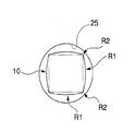
 次に、上述したバイオチップ用支持部材CPを備えるバイオチップ用パッケージ(検査用パッケージ)について、図10乃至図12を参照して説明する。
[Packaging for biochips]
Next, a biochip package (inspection package) including the biochip support member CP described above will be described with reference to FIGS.
 これらの図において、図1乃至図5に示す構成要素と同一の要素については同一符号を付し、その説明を省略する。 In these drawings, the same components as those shown in FIGS. 1 to 5 are designated by the same reference numerals, and the description thereof is omitted.
 図10は、バイオチップBCが支持領域15に固着されたバイオチップ用支持部材CPの外観斜視図である。図11は、バイオチップ用支持部材CPとともに、バイオチップ用パッケージPGを構成するウェルプレート(保持部材)WPの平面図である。図12は、バイオチップ用パッケージPGの断面図である。 FIG. 10 is an external perspective view of the biochip support member CP in which the biochip BC is fixed to the support region 15. FIG. 11 is a plan view of a well plate (holding member) WP constituting the biochip package PG together with the biochip support member CP. FIG. 12 is a cross-sectional view of the biochip package PG.
 バイオチップBCは、基板と生体分子を有している。基板は、例えば板状の部材である。基板は、第1面と、第1面とは反対側の第2面とを有している。生体分子は、基板の第1面側に形成されている。図10に示すように、上述したバイオチップ用支持部材CPの支持領域15には、後述するバイオチップ実装工程S12においてバイオチップBCが固着されて実装される。バイオチップBCは、基板の第2面側でバイオチップ用支持部材CPの支持領域15に固着される。 The biochip BC has a substrate and a biomolecule. The substrate is a plate-like member, for example. The substrate has a first surface and a second surface opposite to the first surface. The biomolecule is formed on the first surface side of the substrate. As shown in FIG. 10, the biochip BC is fixedly mounted on the support region 15 of the biochip support member CP described above in the biochip mounting step S12 described later. The biochip BC is fixed to the support region 15 of the biochip support member CP on the second surface side of the substrate.
 図11に示すように、ウェルプレートWPは、バイオチップ用支持部材CPにおける複数の柱状部材10と対応するそれぞれの位置に保持部25を備えている。保持部25は、図12に示すように、バイオチップBCの生体分子と特異的に反応可能な標的を含む検体Kを保持する保持空間26を備えている。保持空間26の深さは、ウェルプレートWPにバイオチップ用支持部材CPが組み合わされ、柱状部材10が保持空間26に挿入された際にも柱状部材10の支持領域15に支持されたバイオチップBCが底部に接触しない値に設定されている。ウェルプレートWPを形成する材料としては、特に制限はないが、バイオチップ用支持部材CPと一体化させた際の熱膨張量に差が生じないように、バイオチップ用支持部材CPと同じ材料で形成することが好ましい。 As shown in FIG. 11, the well plate WP includes holding portions 25 at respective positions corresponding to the plurality of columnar members 10 in the biochip support member CP. As shown in FIG. 12, the holding unit 25 includes a holding space 26 that holds a specimen K including a target that can specifically react with the biomolecule of the biochip BC. The depth of the holding space 26 is such that the biochip support member CP is combined with the well plate WP, and the biochip BC supported by the support region 15 of the columnar member 10 even when the columnar member 10 is inserted into the holding space 26. Is set to a value that does not touch the bottom. The material for forming the well plate WP is not particularly limited, but is made of the same material as the biochip support member CP so as not to cause a difference in thermal expansion when integrated with the biochip support member CP. It is preferable to form.
 バイオチップ用パッケージPGは、このウェルプレートWP及び上述したバイオチップ用支持部材CPを備えた構成となる。 The biochip package PG includes the well plate WP and the biochip support member CP described above.
 [スクリーニング装置及びスクリーニング方法]
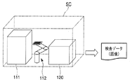
 次に、上記のバイオチップ用パッケージPGを用いてスクリーニングを行う装置及び方法について、図13乃至図15を参照して説明する。
[Screening apparatus and screening method]
Next, an apparatus and method for performing screening using the biochip package PG will be described with reference to FIGS.
 図13は、スクリーニング装置SCの模式図である。スクリーニング装置SCは、分注装置111、測定装置120、及び搬送装置112を備えている。本実施形態におけるスクリーニング装置SCは、上述したバイオチップ用パッケージPGにおけるウェルプレートWPの保持部25に検体Kを分注する分注装置111と、検体Kに含まれる標的と生体分子との親和性を検出する測定装置120と、バイオチップ(生体分子アレイ)BCを分注装置111から測定装置120へ搬送する搬送装置112と、を備える。例えば、分注装置111は、ウェルプレートWPにおける保持部25に、標的を含む検体Kを分注する分注処理が行われるものである。また、分注装置111においては、後述する反応工程、洗浄・乾燥工程、パッケージ一体化工程・パッケージ分離工程等も行われる。 FIG. 13 is a schematic diagram of the screening apparatus SC. The screening device SC includes a dispensing device 111, a measuring device 120, and a transport device 112. The screening apparatus SC in the present embodiment includes a dispensing apparatus 111 that dispenses the specimen K into the holding unit 25 of the well plate WP in the above-described biochip package PG, and the affinity between the target and the biomolecule contained in the specimen K. And a transport device 112 that transports a biochip (biomolecule array) BC from the dispensing device 111 to the measurement device 120. For example, the dispensing apparatus 111 performs a dispensing process for dispensing the sample K containing the target to the holding unit 25 in the well plate WP. In the dispensing apparatus 111, a reaction process, a cleaning / drying process, a package integration process / package separation process, and the like, which will be described later, are also performed.
 図14は、測定装置120の概略構成図である。 FIG. 14 is a schematic configuration diagram of the measuring apparatus 120.
 測定装置120は、バイオチップ用支持部材CP(バイオチップBCに形成されたスポット)を観察する測定装置本体121と、測定装置本体121の動作を制御する制御装置122と、制御装置122に接続された表示装置123とを備えている。制御装置122は、コンピュータシステムを含む。表示装置123は、例えば液晶ディスプレイのようなフラットパネルディスプレイを含む。 The measurement device 120 is connected to the measurement device main body 121 for observing the biochip support member CP (spot formed on the biochip BC), the control device 122 for controlling the operation of the measurement device main body 121, and the control device 122. Display device 123. The control device 122 includes a computer system. The display device 123 includes a flat panel display such as a liquid crystal display.
 測定装置本体121は、光源装置131と、対物レンズ132等を含む光学システム125と、バイオチップ用支持部材CPを支持しながら移動可能なステージ(測定ステージ)126と、接眼部127と、物体を介した光を受光可能なセンサ128を含む観察カメラ129とを備えている。センサ128は、PMT(photomultiplier tube)などの光検出器、CCD(charge coupled device)、CMOSなどの撮像素子が挙げられる(なお、本実施形態において、センサ128は一例として撮像素子を用いている)。測定装置本体121は、ボディ124を備えており、光源装置131、光学システム125、ステージ126、接眼部127及び観察カメラ129のそれぞれは、ボディ124に支持される。 The measurement apparatus main body 121 includes a light source device 131, an optical system 125 including an objective lens 132, a stage (measurement stage) 126 movable while supporting a biochip support member CP, an eyepiece 127, an object And an observation camera 129 including a sensor 128 capable of receiving light via the. Examples of the sensor 128 include a photodetector such as a PMT (photomultiplier tube), an image sensor such as a CCD (charge coupled device), and a CMOS (in this embodiment, the sensor 128 uses an image sensor as an example). . The measurement apparatus main body 121 includes a body 124, and each of the light source device 131, the optical system 125, the stage 126, the eyepiece 127, and the observation camera 129 is supported by the body 124.
 光学システム125は、光源装置131から射出された光を用いてバイオチップ用支持部材CPを照明する照明光学系136と、照明光学系136で照明されたバイオチップ用支持部材CPの像を、センサ128、及び接眼部127の近傍に形成する結像光学系133とを備えている。センサ128及び接眼部127は、結像光学系133の像面側に配置されている。 The optical system 125 uses an illumination optical system 136 that illuminates the biochip support member CP using light emitted from the light source device 131, and an image of the biochip support member CP illuminated by the illumination optical system 136, as a sensor. 128 and an imaging optical system 133 formed in the vicinity of the eyepiece 127. The sensor 128 and the eyepiece 127 are disposed on the image plane side of the imaging optical system 133.
 対物レンズ132は、無限系の対物レンズであり、ステージ126に支持されているバイオチップ用支持部材CPと対向可能である。本実施形態においては、対物レンズ132は、バイオチップ用支持部材の+Z側(上方)に配置されている。 The objective lens 132 is an infinite objective lens and can be opposed to the biochip support member CP supported by the stage 126. In the present embodiment, the objective lens 132 is disposed on the + Z side (above) of the biochip support member.
 光源装置131は、バイオチップBCから蛍光を発生させる所定波長帯域の励起光と、バイオチップBCを観察する所定波長帯域の照明光とを射出可能である。 The light source device 131 can emit excitation light of a predetermined wavelength band that generates fluorescence from the biochip BC and illumination light of a predetermined wavelength band that observes the biochip BC.
 照明光学系136は、光源装置131から射出された光を用いて、励起光または照明光でバイオチップBCを照明する。照明光学系136は、対物レンズ132、及び励起光および照明光と蛍光とを分離可能な光学ユニット137を含む。対物レンズ132は、バイオチップBCを照明するための励起光、及び照明光を射出する。照明光学系136は、ステージ126に支持されているバイオチップBCを、所定の上方(Z方向)から励起光、及び照明光で照明する。また、照明光学系136は、バイオチップBCで生じた蛍光を透過させて結像光学系133へと導く。 The illumination optical system 136 uses the light emitted from the light source device 131 to illuminate the biochip BC with excitation light or illumination light. The illumination optical system 136 includes an objective lens 132 and an optical unit 137 that can separate excitation light, illumination light, and fluorescence. The objective lens 132 emits excitation light and illumination light for illuminating the biochip BC. The illumination optical system 136 illuminates the biochip BC supported by the stage 126 with excitation light and illumination light from a predetermined upper side (Z direction). The illumination optical system 136 transmits the fluorescence generated in the biochip BC and guides it to the imaging optical system 133.
 結像光学系133は、対物レンズ132からの光を分離する光学素子147と、反射ミラー145とを含み、バイオチップBCの像を、センサ128、及び接眼部127の近傍に形成する。光学素子147は、ハーフミラーを含み、入射した光の一部を透過し、一部を反射する。なお、光学素子147は、ダイクロイックミラーであってもよい。また、光学素子147は、光路を切り替える機能を有する全反射ミラー(例、クイックリターンミラー)であってもよい。 The imaging optical system 133 includes an optical element 147 that separates light from the objective lens 132 and a reflection mirror 145, and forms an image of the biochip BC in the vicinity of the sensor 128 and the eyepiece 127. The optical element 147 includes a half mirror, transmits a part of incident light, and reflects a part thereof. The optical element 147 may be a dichroic mirror. Further, the optical element 147 may be a total reflection mirror (for example, a quick return mirror) having a function of switching an optical path.
 ステージ126は、結像光学系133の物体面側で、バイオチップ用支持部材CPを支持する。バイオチップ用支持部材CPは、支持領域15に支持されるバイオチップBCの表面が対物レンズ132と対向するように、ステージ126に支持される。 The stage 126 supports the biochip support member CP on the object plane side of the imaging optical system 133. The biochip support member CP is supported by the stage 126 so that the surface of the biochip BC supported by the support region 15 faces the objective lens 132.
 バイオチップBCから対物レンズ132を介して光学素子147に入射した光の一部は、光学素子147を透過して、接眼レンズ143に導かれ、接眼部127より射出される。バイオチップBC(例、スポット)の像は、結像光学系133により、接眼部127の近傍に形成される。これにより、観察者は、接眼部127を介して、スポットの像を確認できる。 Part of the light incident on the optical element 147 from the biochip BC via the objective lens 132 is transmitted through the optical element 147, guided to the eyepiece lens 143, and emitted from the eyepiece 127. An image of the biochip BC (eg, spot) is formed in the vicinity of the eyepiece 127 by the imaging optical system 133. Thereby, the observer can confirm the image of the spot via the eyepiece 127.
 また、バイオチップBCから対物レンズ132及び対物レンズ146を介して光学素子147に入射した光の一部は、光学素子147及び反射ミラー145で順に反射されて、観察カメラ129のセンサ128に入射する。バイオチップBC(例、スポット)の像は、結像光学系133により、センサ128に形成される。これにより、観察カメラ129のセンサ128は、バイオチップBC(例、スポット)の像情報を取得可能である。 Further, part of the light incident on the optical element 147 from the biochip BC via the objective lens 132 and the objective lens 146 is sequentially reflected by the optical element 147 and the reflection mirror 145 and enters the sensor 128 of the observation camera 129. . An image of the biochip BC (eg, spot) is formed on the sensor 128 by the imaging optical system 133. Thereby, the sensor 128 of the observation camera 129 can acquire image information of the biochip BC (eg, spot).
 図14に示したように、観察カメラ129のセンサ128と制御装置122とは、ケーブル148を介して接続されており、センサ128で取得したバイオチップBC(スポット)の像情報(例、画像信号)は、ケーブル148を介して、制御装置122に出力される。制御装置122は、センサ128からの像情報を、表示装置123を用いて表示する。表示装置123は、センサ128で取得したバイオチップBC(例、スポット)の像情報を拡大して表示することができる。 As shown in FIG. 14, the sensor 128 of the observation camera 129 and the control device 122 are connected via a cable 148, and image information (eg, image signal) of the biochip BC (spot) acquired by the sensor 128. ) Is output to the control device 122 via the cable 148. The control device 122 displays the image information from the sensor 128 using the display device 123. The display device 123 can enlarge and display the image information of the biochip BC (eg, spot) acquired by the sensor 128.
 また、本実施形態においては、ステージ126は、バイオチップ用支持部材CPを支持するステージ定盤150と、ベース部材151上でステージ定盤150を移動する駆動装置152とを備えている。ステージ定盤150は、ベース部材151上において、XY平面内及びZ方向に移動可能である。ステージ126(駆動装置152)と制御装置122とはケーブル149で接続されており、制御装置122は、駆動装置152を用いて、バイオチップ用支持部材CPを支持するステージ定盤150をXY平面内及びZ方向に移動可能である。 In this embodiment, the stage 126 includes a stage surface plate 150 that supports the biochip support member CP, and a drive device 152 that moves the stage surface plate 150 on the base member 151. The stage surface plate 150 is movable on the base member 151 in the XY plane and in the Z direction. The stage 126 (drive device 152) and the control device 122 are connected by a cable 149. The control device 122 uses the drive device 152 to place the stage surface plate 150 that supports the biochip support member CP in the XY plane. And moveable in the Z direction.
 次に、上記バイオチップ用パッケージPGを用いてバイオチップBC(生体分子アレイ)をスクリーニングする方法について、図15に示すフローチャートを用いて説明する。 Next, a method for screening a biochip BC (biomolecule array) using the biochip package PG will be described with reference to the flowchart shown in FIG.
 本実施形態におけるスクリーニング方法は、バイオチップ用支持部材準備工程S11、バイオチップ実装工程S12、ウェルプレート準備工程S13、分注工程S14、パッケージ一体化工程S15、反応工程S16、パッケージ分離工程S17、洗浄・乾燥工程S18、測定(検出)工程S19を含む。 The screening method in the present embodiment includes biochip support member preparation step S11, biochip mounting step S12, well plate preparation step S13, dispensing step S14, package integration step S15, reaction step S16, package separation step S17, and washing. A drying step S18 and a measurement (detection) step S19 are included.
 バイオチップ用支持部材準備工程S11は、上述した柱状部材準備工程S1、基材準備工程S2、取付工程S3、ラップ工程S4を含む。バイオチップ実装工程S12は、上記の準備工程S11で準備されたバイオチップ用支持部材CPの支持領域15にバイオチップBCを実装する。バイオチップBCの支持領域15への固定方法としては、例えば、接着剤を用いることができる。接着剤としては、熱硬化性接着剤や光硬化性接着剤等を用いることができるが、生体分子への熱の影響を考慮すると光硬化性接着剤を用いることが好ましい。接着剤は、バイオチップBCの生体分子が設けられる側と逆側の面に塗布する構成や、柱状部材10の支持領域15に塗布する構成、上記逆側の面と支持領域15の双方に塗布する構成を選択できる。支持領域15には、窪み部16が設けられているため、バイオチップBCの実装時に余分な接着剤は窪み部16に貯溜される。そのため、余分な接着剤がバイオチップBCからはみ出したり、支持領域15からはみ出すことを抑制できる。 The biochip support member preparation step S11 includes the columnar member preparation step S1, the base material preparation step S2, the attachment step S3, and the lapping step S4. In the biochip mounting step S12, the biochip BC is mounted on the support region 15 of the biochip support member CP prepared in the preparation step S11. As a method for fixing the biochip BC to the support region 15, for example, an adhesive can be used. As the adhesive, a thermosetting adhesive, a photocurable adhesive, or the like can be used, but it is preferable to use a photocurable adhesive in consideration of the influence of heat on the biomolecule. The adhesive is applied to the surface of the biochip BC opposite to the side on which the biomolecules are provided, the structure applied to the support region 15 of the columnar member 10, and applied to both the opposite surface and the support region 15. You can select the configuration to do. Since the recess 16 is provided in the support region 15, excess adhesive is stored in the recess 16 when the biochip BC is mounted. Therefore, it is possible to suppress excess adhesive from protruding from the biochip BC or from the support region 15.
 バイオチップBCを支持領域15に実装する際には、まず、バイオチップ用支持部材CPを第1孔部AL1、第2孔部AL2に軸部材を嵌合させて位置合わせした後に、柱状部材10に設けられたマークFMを測定する。これにより、マークFMが形成された柱状部材10の位置(中心位置)が認識される。当該柱状部材10の位置及びこの位置を基準とした他の柱状部材10の位置は既知であるため、測定された柱状部材10の位置を基準として、他の柱状部材10の位置も求められ、求められた位置に応じてバイオチップBCを実装する。 When mounting the biochip BC in the support region 15, first, after aligning the biochip support member CP by fitting the shaft member into the first hole portion AL <b> 1 and the second hole portion AL <b> 2, the columnar member 10. The mark FM provided on is measured. Thereby, the position (center position) of the columnar member 10 on which the mark FM is formed is recognized. Since the position of the columnar member 10 and the position of the other columnar member 10 based on this position are already known, the position of the other columnar member 10 is also obtained and obtained on the basis of the measured position of the columnar member 10. The biochip BC is mounted according to the determined position.
 マークFMは二つの柱状部材10に設けられているため、2つのマークFMを測定した結果と、マークFMの設計位置とに基づいてスケール誤差を求め、スケール誤差を用いて、他の柱状部材10の位置を補正してもよい。ここで、2つのマークFMは、X位置が同一であるため、バイオチップ用支持部材CPを支持するテーブルをY方向に移動させることにより両マークFMを測定することが可能になり測定効率の向上を図ることができる。 Since the mark FM is provided on the two columnar members 10, the scale error is obtained based on the measurement result of the two marks FM and the design position of the mark FM, and the other columnar members 10 are obtained using the scale error. May be corrected. Here, since the two marks FM have the same X position, it is possible to measure both marks FM by moving the table supporting the biochip support member CP in the Y direction, thereby improving the measurement efficiency. Can be achieved.
 上記実施形態では、マークFMを2つの柱状部材10に設ける構成としたが、全ての柱状部材10に設けてもよい。この場合には、柱状部材10毎に位置を検出するため、バイオチップBCの実装精度を高めることができる。この場合についても、柱状部材10が配列されている方向と平行な直線上にマークFMを配置することによって、各マークFMを測定する際に、テーブルを一方向に移動させることにより、複数のマークFMを簡便に測定することが可能となる。 In the above embodiment, the mark FM is provided on the two columnar members 10, but may be provided on all the columnar members 10. In this case, since the position is detected for each columnar member 10, the mounting accuracy of the biochip BC can be increased. Also in this case, by arranging the mark FM on a straight line parallel to the direction in which the columnar members 10 are arranged, when measuring each mark FM, a plurality of marks are moved by moving the table in one direction. It becomes possible to measure FM simply.
 ウェルプレート準備工程S13においては、上述したウェルプレートWPを、例えば、射出成形により製造して準備する。準備されたウェルプレートWPに対しては、分注工程S14において、分注装置111で各保持部25にバイオチップBCに設けられた生体分子と特異的に反応可能な標的を含む検体Kが分注される。検体Kの分注量は、保持部25に柱状部材10が挿入された際に、バイオチップBCが浸る量に設定される。 In the well plate preparation step S13, the well plate WP described above is prepared by, for example, injection molding. For the prepared well plate WP, in the dispensing step S14, a sample K containing a target that can specifically react with a biomolecule provided on the biochip BC in each holding unit 25 is dispensed by the dispensing device 111. Noted. The dispensing amount of the specimen K is set to an amount that the biochip BC is immersed when the columnar member 10 is inserted into the holding unit 25.
 検体Kの分注は、例えば分注ノズルを用いて行う。分注ノズルは、単体で複数の保持部25に順次検体を分注する手順や、複数の分注ノズルをウェルプレートWPに対して一体的に相対移動させる手順、複数の分注ノズルをウェルプレートWPに対してそれぞれ独立して相対移動させる手順等を採用できる。 The sample K is dispensed using, for example, a dispensing nozzle. As for the dispensing nozzle, a procedure for sequentially dispensing a sample to a plurality of holding units 25 alone, a procedure for integrally moving a plurality of dispensing nozzles relative to a well plate WP, and a plurality of dispensing nozzles for a well plate A procedure for moving the WP independently relative to the WP can be adopted.
 保持部25に検体Kが分注された後、パッケージ一体化工程S15において、図12に示すように、バイオチップBCが検体Kに浸るように、柱状部材10が保持部25(保持空間26)に挿入され、ウェルプレートWPとバイオチップ用支持部材CPとが、バイオチップ用パッケージPGとして一体化される。 After the sample K is dispensed into the holding unit 25, the columnar member 10 is held by the holding unit 25 (holding space 26) so that the biochip BC is immersed in the sample K in the package integration step S15 as shown in FIG. The well plate WP and the biochip support member CP are integrated as a biochip package PG.
 反応工程S16においては、バイオチップBC(生体分子)が当該検体Kに浸漬され生体分子と検体Kに含まれる標的との反応処理が所定時間行われる。この反応処理においては、反応を促進させるために、例えば、バイオチップ用パッケージPGに振動や揺動を与えて検体Kを攪拌することが好ましい。 In the reaction step S16, the biochip BC (biomolecule) is immersed in the sample K, and the reaction process between the biomolecule and the target contained in the sample K is performed for a predetermined time. In this reaction process, in order to promote the reaction, for example, it is preferable to stir the specimen K by applying vibration or rocking to the biochip package PG.
 所定時間の反応工程が行われた後、パッケージ分離工程S17でウェルプレートWPとバイオチップ用支持部材CPとを分離する。パッケージ分離工程S17でウェルプレートWPが分離されたバイオチップ用支持部材CPのバイオチップBCに対しては、洗浄・乾燥工程S18において洗浄処理及び乾燥処理が行われる。洗浄処理では、例えば、バイオチップ用支持部材CPに洗浄液が供給されバイオチップBCが洗浄される。バイオチップBCに対する洗浄処理が完了すると乾燥処理が行われる。乾燥処理では、バイオチップBCに付着した洗浄液がブロワ等を用いて乾燥処理される。 After the reaction process for a predetermined time, the well plate WP and the biochip support member CP are separated in the package separation process S17. The biochip BC of the biochip support member CP from which the well plate WP has been separated in the package separation process S17 is subjected to a cleaning process and a drying process in a cleaning / drying process S18. In the cleaning process, for example, the cleaning liquid is supplied to the biochip support member CP to clean the biochip BC. When the cleaning process for the biochip BC is completed, the drying process is performed. In the drying process, the cleaning liquid adhering to the biochip BC is dried using a blower or the like.
 洗浄・乾燥工程S18が完了した後、測定(検出)工程S19に移行する。ウェルプレートWPが取り外されたバイオチップ用支持部材CPは、搬送装置112によって搬送され、測定装置120のステージ126に載置されて測定処理が実施される。 After the washing / drying step S18 is completed, the process proceeds to the measurement (detection) step S19. The biochip support member CP from which the well plate WP has been removed is transported by the transport device 112 and placed on the stage 126 of the measurement device 120 to perform measurement processing.
 バイオチップ用支持部材CPの搬送時には、搬送装置112は、例えば、把持部20を挟持して把持するが、把持部20に断面V字状に形成されY方向に延在する溝部21が設けられているため、搬送時にバイオチップ用支持部材CPが傾く等の不具合を起こすことなく安定した状態で搬送することができる。 When transporting the biochip support member CP, for example, the transport device 112 sandwiches and grips the grip portion 20, but the grip portion 20 is provided with a groove portion 21 that is formed in a V-shaped cross section and extends in the Y direction. Therefore, the biochip support member CP can be transported in a stable state without causing problems such as tilting during transport.
 測定(検出)工程S19においては、上記の測定装置120によって、バイオチップBCに形成されたスポット(例、生体分子)において、バイオチップBCの生体分子と検体Kに含まれる標的との親和性が検出される。例えば、該標的が蛍光色素で蛍光標識されている場合、測定装置120は、励起光によって発生する蛍光色素の蛍光の強度から親和性を検出する。 In the measurement (detection) step S <b> 19, the affinity between the biomolecule on the biochip BC and the target contained in the specimen K is the spot (for example, biomolecule) formed on the biochip BC by the measurement device 120. Detected. For example, when the target is fluorescently labeled with a fluorescent dye, the measuring device 120 detects affinity from the fluorescence intensity of the fluorescent dye generated by the excitation light.
 例えば、測定装置120は、所定のバイオチップBCの表面をZ方向の所定位置に位置決めした後、当該バイオチップBCにおける所定(所定数)のスポットが測定可能となる第1の撮像領域に、バイオチップ用支持部材CPをステージ126によってXY平面内で移動させ、観察用の照明光を用いてスポットの像を撮像する。 For example, the measurement apparatus 120 positions the surface of a predetermined biochip BC at a predetermined position in the Z direction, and then, in a first imaging region where a predetermined (predetermined number) of spots on the biochip BC can be measured. The chip support member CP is moved in the XY plane by the stage 126, and an image of the spot is taken using observation illumination light.
 次に、測定装置120は、光源装置131から照明光を選択して射出させ、バイオチップBCの表面を照明する。光源装置131から射出された照明光は、光学ユニット137で反射光と透過光とに分離されて、部分反射及び部分透過し、部分反射した照明光が対物レンズ132を透過した後に、バイオチップBCの表面を照明する。バイオチップBCの表面で反射した照明光は、対物レンズ132、光学ユニット137を透過して光学素子147に入射する。 Next, the measurement device 120 selects and emits illumination light from the light source device 131 to illuminate the surface of the biochip BC. The illumination light emitted from the light source device 131 is separated into reflected light and transmitted light by the optical unit 137 and partially reflected and partially transmitted. After the partially reflected illumination light passes through the objective lens 132, the biochip BC Illuminate the surface. The illumination light reflected on the surface of the biochip BC passes through the objective lens 132 and the optical unit 137 and enters the optical element 147.
 そして、光学素子147に入射した照明光の一部は、光学素子147を透過して、接眼レンズ127に導かれ、接眼部127より射出される。これにより、バイオチップBCのスポットの像が、接眼部127の近傍に形成される。また、光学素子147に入射した照明光の一部は、光学素子147および反射ミラー145で順次反射されて、観察カメラ129のセンサ128に入射する。 Then, part of the illumination light incident on the optical element 147 passes through the optical element 147, is guided to the eyepiece lens 127, and is emitted from the eyepiece portion 127. Thereby, an image of a spot on the biochip BC is formed in the vicinity of the eyepiece 127. Further, part of the illumination light incident on the optical element 147 is sequentially reflected by the optical element 147 and the reflection mirror 145 and then enters the sensor 128 of the observation camera 129.
 これらにより、センサ128の撮像特性及び所定の倍率に応じた大きさの視野内に複数のスポットの像がセンサ128に形成される。センサ128は、スポットの像情報(スポットの受光情報)及びバイオチップBCに設けられた不図示のアライメントマークの像情報(位置情報)を取得する。制御装置122は、スポットの像情報を記憶するとともに、アライメントマークの位置情報から視野におけるスポット群の配置(X、Y、θZ)を求めて記憶する。 Thus, images of a plurality of spots are formed on the sensor 128 in the field of view having a size corresponding to the imaging characteristics of the sensor 128 and a predetermined magnification. The sensor 128 acquires spot image information (spot light reception information) and image information (position information) of an alignment mark (not shown) provided on the biochip BC. The control device 122 stores the image information of the spot, and obtains and stores the arrangement (X, Y, θZ) of the spot group in the visual field from the position information of the alignment mark.
 この後、測定装置120は、蛍光測定を行うために、光源装置131から射出される光を、例えば所定波長帯域の励起光に切り替える。光源装置131から射出された励起光は、光学ユニット137で反射(全反射)し、対物レンズ132を透過した後に、バイオチップBCの表面(例、スポット)を照明する。励起光で照明された複数のスポットのうち検体Kに含まれるターゲット(標的)と生体分子との特異的な反応により結合したスポットから蛍光が発生する。発生した蛍光は、対物レンズ132、および光学ユニット137を透過して光学素子147に入射する。例えば、特異的な反応によって結合したスポットの親和性は、親和性が高い場合、検出される蛍光強度が高い。 Thereafter, the measurement device 120 switches the light emitted from the light source device 131 to, for example, excitation light in a predetermined wavelength band in order to perform fluorescence measurement. The excitation light emitted from the light source device 131 is reflected (totally reflected) by the optical unit 137, passes through the objective lens 132, and then illuminates the surface (eg, spot) of the biochip BC. Fluorescence is generated from a spot that is bound by a specific reaction between a target (target) contained in the specimen K and a biomolecule among a plurality of spots illuminated with excitation light. The generated fluorescence passes through the objective lens 132 and the optical unit 137 and enters the optical element 147. For example, when the affinity of a spot bound by a specific reaction is high, the detected fluorescence intensity is high.
 そして、照明光によるスポットの測定と同様に、蛍光を発生したスポットの像は、接眼部127の近傍に形成されるとともに、センサ128の視野内に形成される。センサ128は、蛍光を発生したスポットの像情報(スポットの受光情報)を取得する。 Then, similarly to the spot measurement with illumination light, an image of a spot where fluorescence is generated is formed in the vicinity of the eyepiece 127 and also in the field of view of the sensor 128. The sensor 128 acquires image information (spot light reception information) of the spot that generates fluorescence.
 これら照明光によるスポット測定、及び励起光によるスポット測定において、対物レンズ132の光軸方向または光軸と平行な方向で、バイオチップBCがバイオチップ用支持部材CPにおける最も高い(すなわち、対物レンズ132に最も近い)位置となる。測定装置120は、バイオチップBCにおける第1の撮像領域の測定が完了した後、第1の撮像領域と隣り合う第2の撮像領域にバイオチップBCが位置するようにバイオチップ用支持部材CPを移動させる。第2の撮像領域は、第1の撮像領域で撮像したアライメントマークの一部がセンサ128の視野で撮像される位置に設定される。そして、測定装置120は、上記第1の撮像領域に対する撮像処理と同様に、照明光を用いたスポット及びアライメントマークの測定及び蛍光を用いたスポットの測定を実施する。 In the spot measurement using the illumination light and the spot measurement using the excitation light, the biochip BC is the highest in the biochip support member CP in the optical axis direction of the objective lens 132 or in a direction parallel to the optical axis (that is, the objective lens 132). Closest position). After the measurement of the first imaging region in the biochip BC is completed, the measuring device 120 sets the biochip support member CP so that the biochip BC is positioned in the second imaging region adjacent to the first imaging region. Move. The second imaging area is set to a position where a part of the alignment mark imaged in the first imaging area is imaged in the field of view of the sensor 128. And the measuring apparatus 120 performs the measurement of the spot using illumination light, and the measurement of the spot using fluorescence similarly to the imaging process with respect to the said 1st imaging area.
 そして、全てのスポットの測定が完了するまで複数の撮像領域の測定処理を実施した後、制御装置122は、各撮像領域におけるアライメントマークの測定結果から照明光によるスポットの測定結果を画面合成するとともに、蛍光によるスポットの測定結果を画面合成する。画面合成された測定結果を比較することにより、検体Kのターゲットと生体分子72とが特異的な反応により結合したスポットのバイオチップBCにおけるアドレスを測定することができる。 Then, after performing measurement processing of a plurality of imaging areas until measurement of all the spots is completed, the control device 122 combines the measurement results of the spots by the illumination light from the measurement results of the alignment marks in each imaging area, and Then, the spot measurement result by fluorescence is synthesized on the screen. By comparing the measurement results synthesized on the screen, the address on the biochip BC of the spot where the target of the specimen K and the biomolecule 72 are bound by a specific reaction can be measured.
 本実施形態では、バイオチップを簡便に測定可能とする。バイオチップ用支持部材CPは反り等の変形が抑制されており、また、ステージに支持される面である、バイオチップ用支持部材CPにおける基材BPの裏面BPbとバイオチップBCが支持される、複数の柱状部材10が備える支持領域15とが平坦化及び平滑化されているため、各支持領域15に支持されたバイオチップBCを測定する際の焦点合わせを最小限に抑えることができる。そのため、バイオチップBCを測定する際のスループット低下を抑えることが可能となる。 In this embodiment, the biochip can be easily measured. The biochip support member CP is suppressed from deformation such as warpage, and the back surface BPb of the base material BP and the biochip BC in the biochip support member CP, which are surfaces supported by the stage, are supported. Since the support regions 15 included in the plurality of columnar members 10 are flattened and smoothed, focusing when measuring the biochip BC supported by each support region 15 can be minimized. Therefore, it is possible to suppress a decrease in throughput when measuring the biochip BC.
 以上、添付図面を参照しながら本発明に係る好適な実施形態について説明したが、本発明は係る例に限定されないことは言うまでもない。上述した例において示した各構成部材の諸形状や組み合わせ等は一例であって、本発明の主旨から逸脱しない範囲において設計要求等に基づき種々変更可能である。 As described above, the preferred embodiments according to the present invention have been described with reference to the accompanying drawings, but it goes without saying that the present invention is not limited to such examples. Various shapes, combinations, and the like of the constituent members shown in the above-described examples are examples, and various modifications can be made based on design requirements and the like without departing from the gist of the present invention.
 例えば、上記実施形態では、バイオチップ用支持部材CPの柱状部材10及びウェルプレートWPの保持部25の双方が平面視円形であり、柱状部材10と保持部25との間の隙間量が一定になる構成を例示したが、これに限定されるものではなく、隙間量が異なる領域を設ける構成であってもよい。例えば、図16及び図17に示すように、柱状部材10は、四角柱に対して、角にR面取り加工を施し、且つ、4つの側面を曲面で形成した形状であってもよい。一例として、柱状部材10は、4つの側面部が曲面(第1領域)R1で形成されるとともに、これらの曲面R1が交叉する角の部分は曲面R1よりも曲率の大きな曲面(第2領域)R2の丸み(所謂、丸み面取り)が付与されるような形状であってもよい。この構成を採ることにより、曲面R1と保持部25との間の隙間量と、曲面R2と保持部25との間の隙間量とを異ならせることができる。 For example, in the above embodiment, both the columnar member 10 of the biochip support member CP and the holding portion 25 of the well plate WP are circular in plan view, and the gap amount between the columnar member 10 and the holding portion 25 is constant. Although the structure which becomes is illustrated, it is not limited to this, The structure which provides the area | region from which the gap | interval amount differs may be sufficient. For example, as shown in FIGS. 16 and 17, the columnar member 10 may have a shape in which an R-chamfering process is performed on a corner of a quadrangular column and four side surfaces are formed as curved surfaces. As an example, the columnar member 10 has four side surfaces formed by a curved surface (first region) R1, and the corner portion where these curved surfaces R1 intersect has a curved surface (second region) having a larger curvature than the curved surface R1. The shape may be such that roundness of R2 (so-called round chamfering) is imparted. By adopting this configuration, the gap amount between the curved surface R1 and the holding portion 25 and the gap amount between the curved surface R2 and the holding portion 25 can be made different.
 柱状部材10と保持部25との間の隙間量が一定で、当該隙間に検体Kが入り込んだ場合には、保持部25から柱状部材10を抜くときに保持空間26が負圧となってしまい柱状部材10が抜きづらくなり、パッケージ分離に支障を来す虞がある。そのため、図16及び図17に示すように、柱状部材10と保持部25との間の隙間量を異ならせることにより、隙間量が大きい領域から空気が入り込みやすくなるため、上記のパッケージ分離が容易になる。 When the amount of the gap between the columnar member 10 and the holding unit 25 is constant and the sample K enters the gap, the holding space 26 becomes negative pressure when the columnar member 10 is pulled out of the holding unit 25. There is a possibility that the columnar member 10 is difficult to be pulled out and hinders package separation. Therefore, as shown in FIGS. 16 and 17, by making the gap amount between the columnar member 10 and the holding portion 25 different, air can easily enter from an area where the gap amount is large. become.
 また、上記実施形態では、柱状部材10を基材BPに対して取り付ける取付部JTが溶着部とする構成を例示したが、これに限られず、例えば、接着剤を用いて柱状部材10を基材BPに取り付ける構成であってもよい。この場合に用いる接着剤としては、熱硬化性接着剤であっても光硬化性接着剤のいずれであってもよいが、基材BPに与える熱の影響を考慮すると光硬化性接着剤を用いることが好ましい。 Moreover, in the said embodiment, although the attachment part JT which attaches the columnar member 10 with respect to the base material BP illustrated the structure made into a welding part, it is not restricted to this, For example, the columnar member 10 is used as a base material using an adhesive agent. The structure attached to BP may be sufficient. The adhesive used in this case may be either a thermosetting adhesive or a photocurable adhesive, but a photocurable adhesive is used in consideration of the influence of heat on the base material BP. It is preferable.
 また、上記実施形態では、内部空間14を有する柱状部材10を用いたが、これに限るものではなく、中実の柱状部材を用いてもよいし、棒状部材を用いてもよい。なお、柱状部材10の形状として、円柱形状でもよいし、四角柱形状でもよいし、凸形状でもよい。凸形状の柱状部材は、一例として、底面及び天面が円形状であり且つ天面の面積が底面の面積よりも小さい凸形状でもよいし、底面及び天面が矩形状であり且つ天面の面積が底面の面積よりも小さい凸形状でもよい。また、柱状部材10を樹脂材で形成する場合も、射出成形に限られず、押出成形等の他の製法を用いてもよい。また、柱状部材10及び基材BPの材料は、上述した樹脂材に限定されない。例えば、柱状部材を溶融石英棒で形成し、基材BPを硼酸珪酸ガラスで形成する構成とし、これらを接着剤を介して取り付ける構成としてもよい。 In the above embodiment, the columnar member 10 having the internal space 14 is used. However, the present invention is not limited to this, and a solid columnar member or a rod-shaped member may be used. Note that the columnar member 10 may have a columnar shape, a quadrangular columnar shape, or a convex shape. As an example, the convex columnar member may have a convex shape in which the bottom surface and the top surface are circular and the area of the top surface is smaller than the area of the bottom surface, or the bottom surface and the top surface are rectangular and the top surface is A convex shape having an area smaller than the area of the bottom surface may be used. Moreover, when forming the columnar member 10 with a resin material, it is not restricted to injection molding, You may use other manufacturing methods, such as extrusion molding. Moreover, the material of the columnar member 10 and the base material BP is not limited to the resin material mentioned above. For example, the columnar member may be formed of a fused quartz rod, the base material BP may be formed of borosilicate glass, and these may be attached via an adhesive.
 なお、基材BPは、溶着によって柱状部材10を取り付ける領域の位置合わせするマーク部を第1面BPaに有していてもよい。該マーク部は、基材BPの第1面BPaに溶着によって柱状部材10を取り付ける場合に柱状部材10が取り付けられる位置を示している。該マーク部は、例えば、線状マークや、柱状部材10が挿入される溝部などがある。 Note that the base material BP may have a mark portion on the first surface BPa for aligning a region where the columnar member 10 is attached by welding. This mark part has shown the position where the columnar member 10 is attached when attaching the columnar member 10 to the 1st surface BPa of the base material BP by welding. Examples of the mark portion include a linear mark and a groove portion into which the columnar member 10 is inserted.
 また、上記実施形態では、基材BPに柱状部材10を6×4の24個配列する構成を例示したが、これは一例であり、単数の柱状部材10を基材BPに取り付ける構成や、他の個数(例えば12×8の96個)で配列する構成であってもよいことは言うまでもない。 Moreover, in the said embodiment, although the structure which arrange | positions the columnar member 10 24 24 of 6x4 on the base material BP was illustrated, this is an example, the structure which attaches the single columnar member 10 to the base material BP, etc. Needless to say, it may be arranged in a number (for example, 96 of 12 × 8).
 10…柱状部材、 11…円筒部、 12…天板部、 13…突起部、 14…内部空間、 15…支持領域、 16…窪み部、 17…開口部、 20…取付部、 25…保持部、 30…連結部、 31…分離部、 40…保持壁部(位置合わせ部)、 111…分注装置、 120…測定装置(検出装置)、 BC…バイオチップ、 BP…基材、
 BPa…表面(第1面)、 BPb…裏面(第2面)、 BPc…側面(第3面)、 CP…バイオチップ用支持部材、 FM…マーク、 JG2…超音波ホーン(振動子)、
 JG11…治具(第1治具)、  JG12…治具(第2治具)、 JT…取付部(溶着部)、 K…検体、 PG…バイオチップ用パッケージ、 SC…スクリーニング装置、 WP…ウェルプレート(保持部材)
DESCRIPTION OF SYMBOLS 10 ... Columnar member, 11 ... Cylindrical part, 12 ... Top plate part, 13 ... Projection part, 14 ... Internal space, 15 ... Support area, 16 ... Depression part, 17 ... Opening part, 20 ... Mounting part, 25 ... Holding part , 30 ... connecting part, 31 ... separating part, 40 ... holding wall part (alignment part), 111 ... dispensing device, 120 ... measuring device (detecting device), BC ... biochip, BP ... base material,
BPa ... Front surface (first surface), BPb ... Back surface (second surface), BPc ... Side surface (third surface), CP ... Biochip support member, FM ... Mark, JG2 ... Ultrasonic horn (vibrator),
JG11 ... Jig (first jig), JG12 ... Jig (second jig), JT ... Mounting part (welding part), K ... Sample, PG ... Biochip package, SC ... Screening device, WP ... Well Plate (holding member)

Claims (31)

  1.  基材と、
     前記基材とは別の部材であって、生体分子が形成されたバイオチップを支持可能な支持領域を一端側に備えるとともに他端側で取付部を介して前記基材に取り付けられた柱状部材と、
     を備えるバイオチップ用支持部材。
    A substrate;
    A columnar member that is a member different from the base material and includes a support region on one end side that can support a biochip on which a biomolecule is formed, and is attached to the base material on the other end side via an attachment portion. When,
    A biochip support member comprising:
  2.  前記取付部は、前記基材と前記柱状部材との少なくとも一方に形成されており、
     前記柱状部材は、溶着により前記取付部を溶融させて前記基板に取り付けられている
     請求項1に記載のバイオチップ用支持部材。
    The mounting portion is formed on at least one of the base material and the columnar member,
    The biochip support member according to claim 1, wherein the columnar member is attached to the substrate by melting the attachment portion by welding.
  3.  前記柱状部材は、前記他端側に開口部を有し、前記基材と閉空間を形成している
     請求項1または2に記載のバイオチップ用支持部材。
    The biochip support member according to claim 1, wherein the columnar member has an opening on the other end side to form a closed space with the base material.
  4.  前記柱状部材は、前記支持領域に形成された窪み部を備える請求項1から3のいずれか一項に記載のバイオチップ用支持部材。 4. The biochip support member according to claim 1, wherein the columnar member includes a recess formed in the support region. 5.
  5.  前記柱状部材は、該柱状部材の位置の指標となるマークを備える請求項1から4のいずれか一項に記載のバイオチップ用支持部材。 The biochip support member according to any one of claims 1 to 4, wherein the columnar member includes a mark serving as an index of a position of the columnar member.
  6.  前記マークは、前記支持領域に設けられている
     請求項5に記載のバイオチップ用支持部材。
    The biochip support member according to claim 5, wherein the mark is provided in the support region.
  7.  前記柱状部材は、前記基材に複数取り付けられており、
     前記マークは、複数の前記柱状部材それぞれの前記支持領域に設けられている
     請求項6に記載のバイオチップ用支持部材。
    A plurality of the columnar members are attached to the base material,
    The biochip support member according to claim 6, wherein the mark is provided in the support region of each of the plurality of columnar members.
  8.  複数の前記柱状部材のうち、少なくとも一部は、前記支持領域の中心が所定方向に沿って配列され、
     前記マークは、前記所定方向と平行な直線上に設けられている
     請求項7に記載のバイオチップ用支持部材。
    At least a part of the plurality of columnar members is arranged such that the center of the support region is along a predetermined direction,
    The biochip support member according to claim 7, wherein the mark is provided on a straight line parallel to the predetermined direction.
  9.  前記マークは、複数の前記柱状部材それぞれの前記支持領域の中心をとおる直線上に設けられている
     請求項8に記載のバイオチップ用支持部材。
    The biochip support member according to claim 8, wherein the mark is provided on a straight line passing through the center of the support region of each of the plurality of columnar members.
  10.  前記基材は、前記取付部を介して前記柱状部材が取り付けられる第1面と、前記第1面とは反対側の第2面とを含み、前記第1面から前記第2面までを貫通した穴と、前記第1面から前記第2面までを貫通した長穴とを備える
     請求項7から9のいずれか一項に記載のバイオチップ用支持部材。
    The base material includes a first surface to which the columnar member is attached via the attachment portion, and a second surface opposite to the first surface, and penetrates from the first surface to the second surface. The biochip support member according to any one of claims 7 to 9, further comprising: a hole that has been formed and an elongated hole that extends from the first surface to the second surface.
  11.  前記穴及び前記長穴は、前記穴の中心と前記長穴の中心とをとおる直線が、複数の前記柱状部材それぞれの前記支持領域の中心をとおる直線と平行になるように、前記基材に設けられている
     請求項10に記載のバイオチップ用支持部材。
    The hole and the long hole are formed on the base material so that a straight line passing through the center of the hole and the center of the long hole is parallel to a straight line passing through the center of the support region of each of the plurality of columnar members. The biochip support member according to claim 10, wherein the biochip support member is provided.
  12.  前記基材は、前記第1面の外縁と前記第2面の外縁とに沿って形成された第3面を含み、前記第3面に設けられた溝を備える
     請求項10又は11に記載のバイオチップ用支持部材。
    The said base material is provided with the groove | channel provided in the said 3rd surface including the 3rd surface formed along the outer edge of the said 1st surface, and the outer edge of the said 2nd surface. Biochip support member.
  13.  基材と、
     前記基材とは別の部材であって、生体分子が形成されたバイオチップを支持可能な支持領域を一端側に備える柱状部材と、
     前記基材と前記柱状部材の他端側との間に介装された溶着部と、
     を備えるバイオチップ用支持部材。
    A substrate;
    A columnar member that is a member different from the base material and includes a support region on one end side that can support a biochip on which a biomolecule is formed,
    A welded portion interposed between the base material and the other end of the columnar member;
    A biochip support member comprising:
  14.  前記溶着部は、前記基材と前記柱状部材との少なくとも一方の一部が溶融した後に硬化して形成される
     請求項13に記載のバイオチップ用支持部材。
    The biochip support member according to claim 13, wherein the welded portion is formed by curing after at least a part of at least one of the base material and the columnar member is melted.
  15.  請求項1から14のいずれか一項に記載のバイオチップ用支持部材と、
     前記生体分子と特異的に反応可能な標的を含む検体を保持可能な保持部を備える保持部材と、
     を備えるバイオチップ用パッケージ。
    The biochip support member according to any one of claims 1 to 14,
    A holding member comprising a holding part capable of holding a specimen containing a target capable of specifically reacting with the biomolecule;
    A biochip package comprising:
  16.  前記保持部と前記柱状部材とは、前記保持部に前記柱状部材が挿入されたときに、第1の隙間量の第1領域と、第2の隙間量の第2領域とを形成する
     請求項15に記載のバイオチップ用パッケージ。
    The holding portion and the columnar member form a first region having a first gap amount and a second region having a second gap amount when the columnar member is inserted into the holding portion. 15. The biochip package according to 15.
  17.  請求項15又は16に記載のバイオチップ用パッケージにおける前記保持部に前記検体を分注する分注装置と、
    前記検体に含まれる前記標的と前記生体分子との親和性を検出する検出装置と、
    を備えるスクリーニング装置。
    Dispensing device for dispensing the specimen into the holding part in the biochip package according to claim 15 or 16,
    A detection device for detecting the affinity between the target and the biomolecule contained in the specimen;
    A screening apparatus comprising:
  18.  基材を準備する第1工程と、
     前記基材とは別の部材であって、生体分子が形成されたバイオチップを支持可能な支持領域を一端側に備える柱状部材を準備する第2工程と、
     前記柱状部材の他端側を前記基材に取付部を介して取り付ける第3工程と、
     を含むバイオチップ用支持部材の製造方法。
    A first step of preparing a substrate;
    A second step of preparing a columnar member which is a member different from the base material and includes a support region on one end side capable of supporting a biochip on which a biomolecule is formed;
    A third step of attaching the other end of the columnar member to the base material via an attachment portion;
    The manufacturing method of the supporting member for biochips containing this.
  19.  前記第3工程は、前記基材と前記柱状部材との少なくとも一方の一部を前記取付部として溶融する工程と、
     溶融した前記取付部を介して、前記柱状部材の他端側を前記基材に溶着する工程と、
     を含む請求項18に記載のバイオチップ用支持部材の製造方法。
    The third step is a step of melting at least one part of the base member and the columnar member as the attachment portion;
    A step of welding the other end of the columnar member to the base material via the melted attachment portion;
    The manufacturing method of the supporting member for biochips of Claim 18 containing this.
  20.  前記第3工程は、前記基材と前記柱状部材との少なくとも一方に超音波振動及び圧力を加える工程を含む
     請求項18又は19に記載のバイオチップ用支持部材の製造方法。
    The method for manufacturing a biochip support member according to claim 18, wherein the third step includes a step of applying ultrasonic vibration and pressure to at least one of the base material and the columnar member.
  21.  前記支持領域をラップ加工する第4工程を含む
     請求項18から20のいずれか一項に記載のバイオチップ用支持部材の製造方法。
    The manufacturing method of the supporting member for biochips as described in any one of Claims 18-20 including the 4th process of lapping the said support area | region.
  22.  前記ラップ加工を、前記第3工程の後に行う
     請求項21に記載のバイオチップ用支持部材の製造方法。
    The method for manufacturing a biochip support member according to claim 21, wherein the lapping is performed after the third step.
  23.  前記基材は、前記柱状部材の他端側が取り付けられる第1面と、該第1面と逆側の第2面とを備え、
     前記第4工程前に前記基材の前記第2面をラップ加工する工程を含む
     請求項21又は22に記載のバイオチップ用支持部材の製造方法。
    The base material includes a first surface to which the other end side of the columnar member is attached, and a second surface opposite to the first surface,
    The manufacturing method of the supporting member for biochips of Claim 21 or 22 including the process of lapping the said 2nd surface of the said base material before a said 4th process.
  24.  前記第3工程前に前記基材の前記第1面をラップ加工する工程を含む
     請求項23に記載のバイオチップ用支持部材の製造方法。
    The manufacturing method of the support member for biochips of Claim 23 including the process of lapping the said 1st surface of the said base material before a said 3rd process.
  25.  前記第2工程は、複数の前記柱状部材と、該複数の柱状部材を前記基材にそれぞれ取り付けられる配置で連結する連結部とを一体的に成形する工程とを含む
     請求項18から24のいずれか一項に記載のバイオチップ用支持部材の製造方法。
    The said 2nd process includes the process of shape | molding integrally the some said columnar member and the connection part which connects these columnar members by the arrangement | positioning attached to the said base material, respectively. A method for producing a biochip support member according to claim 1.
  26.  前記連結部は、前記柱状部材の軸線方向で前記他端側の端部から離間した位置で前記柱状部材を連結する
     請求項25に記載のバイオチップ用支持部材の製造方法。
    The method for manufacturing a support member for a biochip according to claim 25, wherein the connecting portion connects the columnar member at a position separated from the end on the other end side in the axial direction of the columnar member.
  27.  前記第3工程の前に、前記連結部で連結された前記複数の柱状部材を前記基材に載置することと、
     前記基材に載置された前記複数の柱状部材に、前記基材と前記柱状部材との少なくとも一方の一部を溶融するための振動子を当接させるために、前記柱状部材と前記振動子とを柱状部材の軸線方向に相対移動させることと、
     前記柱状部材と前記振動子との相対移動時に、前記振動子に設けた分離部によって前記柱状部材と前記連結部とを分離することと、
     を含む請求項25又は26に記載のバイオチップ用支持部材の製造方法。
    Before the third step, placing the plurality of columnar members connected by the connecting portion on the base material;
    In order to bring a vibrator for melting at least a part of at least one of the base material and the columnar member into contact with the plurality of columnar members placed on the base material, the columnar member and the vibrator Relative movement in the axial direction of the columnar member,
    Separating the columnar member and the connecting portion by a separation portion provided in the vibrator at the time of relative movement between the columnar member and the vibrator;
    The manufacturing method of the supporting member for biochips of Claim 25 or 26 containing this.
  28.  前記第3工程の前に、前記複数の柱状部材を前記基材にそれぞれ取り付けられる配置に位置合わせする位置合わせ部を有する治具に前記複数の柱状部材をセットして位置あわせすることと、
     前記治具によって位置合わせされた前記複数の柱状部材に前記基材を当接させることと、
     を含む請求項18から24のいずれか一項に記載のバイオチップ用支持部材の製造方法。
    Prior to the third step, setting and aligning the plurality of columnar members on a jig having an alignment section that aligns the plurality of columnar members with the arrangement attached to the base material,
    Bringing the base material into contact with the plurality of columnar members aligned by the jig;
    The manufacturing method of the supporting member for biochips as described in any one of Claims 18-24 containing this.
  29.  前記複数の柱状部材の他端側を下方から支持して前記位置合わせをする第1治具を用い、前記複数の柱状部材を位置合わせすることと、
     前記複数の柱状部材の一端側を下方から支持して前記位置合わせをする第2治具を、前記複数の柱状部材を下方から支持する第1治具に位置決めして取り付けることと、
     位置決めされた前記第1治具及び第2治具を上下反転し、前記第2治具によって前記複数の柱状部材の一端側を下方から支持して前記位置合わせをすることと、
     前記第2治具から前記第1治具を取り外すことと、
     一端側が下方から支持された前記複数の柱状部材の他端側に前記基材を当接させることと、
     を含む請求項28に記載のバイオチップ用支持部材の製造方法。
    Using the first jig that supports the other end side of the plurality of columnar members from below and aligns the plurality of columnar members, and aligning the plurality of columnar members;
    Positioning and attaching a second jig that supports the one end side of the plurality of columnar members from below and positions the second jig to support the plurality of columnar members from below;
    The first jig and the second jig that are positioned are turned upside down, the one end side of the plurality of columnar members is supported from below by the second jig, and the alignment is performed;
    Removing the first jig from the second jig;
    Bringing the base material into contact with the other end side of the plurality of columnar members whose one end side is supported from below;
    The manufacturing method of the supporting member for biochips of Claim 28 containing this.
  30.  請求項18から29のいずれか一項に記載の製造方法で製造されたバイオチップ用支持部材を準備することと、
     前記生体分子と特異的に反応可能な標的を含む検体を保持可能な保持部を備える保持部材を準備することと、
     前記柱状部材の前記支持領域に前記バイオチップを配置して固定することと、
     前記バイオチップが前記検体で浸るように前記保持部に前記検体を分注することと、
     前記標的と前記生体分子とを前記検体の分注された前記保持部内で反応させることと、
     前記反応後に、前記バイオチップ用支持部材と前記保持部材とを分離することと、
     分離した前記バイオチップ用支持部材において、前記標的と前記生体分子との親和性を検出すること、
     を含むスクリーニング方法。
    Preparing a biochip support member produced by the production method according to any one of claims 18 to 29;
    Preparing a holding member comprising a holding part capable of holding a specimen containing a target capable of specifically reacting with the biomolecule;
    Placing and fixing the biochip in the support region of the columnar member;
    Dispensing the sample to the holding portion so that the biochip is immersed in the sample;
    Reacting the target and the biomolecule in the holding portion into which the specimen is dispensed;
    After the reaction, separating the biochip support member and the holding member;
    In the separated support member for biochip, detecting the affinity between the target and the biomolecule;
    A screening method comprising:
  31.  前記バイオチップを前記支持領域に配置する前に、前記柱状部材に備えられた前記柱状部材の位置の指標となるマークを検出すること、
     を含む請求項30記載のスクリーニング方法。
    Before placing the biochip in the support region, detecting a mark serving as an index of the position of the columnar member provided in the columnar member;
    The screening method according to claim 30 comprising:
PCT/JP2014/070230 2013-08-30 2014-07-31 Biochip support member, method for manufacturing biochip support member, biochip package, screening device, and screening method WO2015029691A1 (en)

Priority Applications (3)

Application Number Priority Date Filing Date Title
EP14840291.0A EP3040723A4 (en) 2013-08-30 2014-07-31 Biochip support member, method for manufacturing biochip support member, biochip package, screening device, and screening method
JP2015534105A JPWO2015029691A1 (en) 2013-08-30 2014-07-31 Biochip support member, biochip support member manufacturing method, biochip package, screening apparatus, and screening method
US15/053,587 US20160193608A1 (en) 2013-08-30 2016-02-25 Biochip support member, method for manufacturing biochip support member, biochip package, screening device, and screening method

Applications Claiming Priority (2)

Application Number Priority Date Filing Date Title
JP2013-180248 2013-08-30
JP2013180248 2013-08-30

Related Child Applications (1)

Application Number Title Priority Date Filing Date
US15/053,587 Continuation US20160193608A1 (en) 2013-08-30 2016-02-25 Biochip support member, method for manufacturing biochip support member, biochip package, screening device, and screening method

Publications (1)

Publication Number Publication Date
WO2015029691A1 true WO2015029691A1 (en) 2015-03-05

Family

ID=52586265

Family Applications (1)

Application Number Title Priority Date Filing Date
PCT/JP2014/070230 WO2015029691A1 (en) 2013-08-30 2014-07-31 Biochip support member, method for manufacturing biochip support member, biochip package, screening device, and screening method

Country Status (4)

Country Link
US (1) US20160193608A1 (en)
EP (1) EP3040723A4 (en)
JP (2) JPWO2015029691A1 (en)
WO (1) WO2015029691A1 (en)

Cited By (6)

* Cited by examiner, † Cited by third party
Publication number Priority date Publication date Assignee Title
CN108982887A (en) * 2017-05-31 2018-12-11 台湾生捷科技股份有限公司 Micro array carrier assembly
US10175234B2 (en) 2012-09-28 2019-01-08 Vibrant Holdings, Llc Methods, systems, and arrays for biomolecular analysis
US20190030528A1 (en) * 2015-10-29 2019-01-31 John J. Rajasekaran Methods, tools, and tool assemblies for biomolecular analysis using microarrays
US10799845B2 (en) 2012-11-14 2020-10-13 Vibrant Holdings, Llc Substrates, systems, and methods for array synthesis and biomolecular analysis
US11168365B2 (en) 2017-05-26 2021-11-09 Vibrant Holdings, Llc Photoactive compounds and methods for biomolecule detection and sequencing
US11565231B2 (en) 2012-02-07 2023-01-31 Vibrant Holdings, Llc Substrates, peptide arrays, and methods

Families Citing this family (3)

* Cited by examiner, † Cited by third party
Publication number Priority date Publication date Assignee Title
USD820904S1 (en) * 2016-01-20 2018-06-19 Digital Music Corporation Pedal board
CA3043708A1 (en) 2016-11-17 2018-05-24 Cleveland State University Chip platforms for microarray 3d bioprinting
US11262349B2 (en) 2017-10-11 2022-03-01 Cleveland State University Multiplexed immune cell assays on a micropillar/microwell chip platform

Citations (9)

* Cited by examiner, † Cited by third party
Publication number Priority date Publication date Assignee Title
JPH0516241A (en) * 1991-07-16 1993-01-26 Fujitsu Ltd Method for fusing plastic parts
US5722553A (en) * 1995-03-31 1998-03-03 Hovatter; Kenneth P. Integral assembly of microcentrifuge strip tubes having independently tethered angularly related seal caps
JP2004045179A (en) * 2002-07-11 2004-02-12 Nisshinbo Ind Inc Base material for microarray
JP2005513457A (en) 2001-12-19 2005-05-12 アフィメトリックス インコーポレイテッド Array plate and method for constructing array plate
JP2005528582A (en) * 2001-09-07 2005-09-22 コーニング インコーポレイテッド Array based on a microcolumn platform for high-throughput analysis
JP2006153877A (en) * 1994-06-08 2006-06-15 Affymetrix Inc Method and system for packaging of chips
JP2006258508A (en) * 2005-03-15 2006-09-28 Sumitomo Bakelite Co Ltd Bonding method of plastic member, and biochip and micro analysis chip manufactured using method
US20120135890A1 (en) * 2010-11-29 2012-05-31 Electronics And Telecommunications Research Institute Biomolecule array and method of fabricating biomolecule array chip using the same
US20130081483A1 (en) * 2011-09-30 2013-04-04 Samsung Electro-Mechanics Co., Ltd. Biochip

Family Cites Families (5)

* Cited by examiner, † Cited by third party
Publication number Priority date Publication date Assignee Title
US4154795A (en) * 1976-07-23 1979-05-15 Dynatech Holdings Limited Microtest plates
CA2048150A1 (en) * 1990-09-14 1992-03-15 Karl V. Thomsen High frequency welding of thermoplastic belts
CN1444646A (en) * 2000-02-23 2003-09-24 齐翁米克斯股份有限公司 Chips having elevated sample surfaces
US7531140B2 (en) * 2005-12-29 2009-05-12 Corning Incorporated Multiwell plate having transparent well bottoms and method for making the mulitiwell plate
US8374818B2 (en) * 2008-12-19 2013-02-12 Affymetrix, Inc. System, method and apparatus for calibrating inspection tools

Patent Citations (9)

* Cited by examiner, † Cited by third party
Publication number Priority date Publication date Assignee Title
JPH0516241A (en) * 1991-07-16 1993-01-26 Fujitsu Ltd Method for fusing plastic parts
JP2006153877A (en) * 1994-06-08 2006-06-15 Affymetrix Inc Method and system for packaging of chips
US5722553A (en) * 1995-03-31 1998-03-03 Hovatter; Kenneth P. Integral assembly of microcentrifuge strip tubes having independently tethered angularly related seal caps
JP2005528582A (en) * 2001-09-07 2005-09-22 コーニング インコーポレイテッド Array based on a microcolumn platform for high-throughput analysis
JP2005513457A (en) 2001-12-19 2005-05-12 アフィメトリックス インコーポレイテッド Array plate and method for constructing array plate
JP2004045179A (en) * 2002-07-11 2004-02-12 Nisshinbo Ind Inc Base material for microarray
JP2006258508A (en) * 2005-03-15 2006-09-28 Sumitomo Bakelite Co Ltd Bonding method of plastic member, and biochip and micro analysis chip manufactured using method
US20120135890A1 (en) * 2010-11-29 2012-05-31 Electronics And Telecommunications Research Institute Biomolecule array and method of fabricating biomolecule array chip using the same
US20130081483A1 (en) * 2011-09-30 2013-04-04 Samsung Electro-Mechanics Co., Ltd. Biochip

Non-Patent Citations (1)

* Cited by examiner, † Cited by third party
Title
See also references of EP3040723A4 *

Cited By (12)

* Cited by examiner, † Cited by third party
Publication number Priority date Publication date Assignee Title
US11565231B2 (en) 2012-02-07 2023-01-31 Vibrant Holdings, Llc Substrates, peptide arrays, and methods
US10175234B2 (en) 2012-09-28 2019-01-08 Vibrant Holdings, Llc Methods, systems, and arrays for biomolecular analysis
US10746732B2 (en) 2012-09-28 2020-08-18 Vibrant Holdings, Llc Methods, systems, and arrays for biomolecular analysis
US11674956B2 (en) 2012-09-28 2023-06-13 Vibrant Holdings, Llc Methods, systems, and arrays for biomolecular analysis
US11815512B2 (en) 2012-09-28 2023-11-14 Vibrant Holdings, Llc Methods, systems, and arrays for biomolecular analysis
US10799845B2 (en) 2012-11-14 2020-10-13 Vibrant Holdings, Llc Substrates, systems, and methods for array synthesis and biomolecular analysis
US20190030528A1 (en) * 2015-10-29 2019-01-31 John J. Rajasekaran Methods, tools, and tool assemblies for biomolecular analysis using microarrays
EP3368909A4 (en) * 2015-10-29 2019-07-03 Vibrant Holdings, LLC Methods, tools, and tool assemblies for biomolecular analysis using microarrays
US11033904B2 (en) 2015-10-29 2021-06-15 Vibrant Holdings, Llc Methods, tools, and tool assemblies for biomolecular analysis using microarrays
AU2019284016B2 (en) * 2015-10-29 2021-08-12 Vibrant Holdings, Llc Methods, tools, and tool assemblies for biomolecular analysis using microarrays
US11168365B2 (en) 2017-05-26 2021-11-09 Vibrant Holdings, Llc Photoactive compounds and methods for biomolecule detection and sequencing
CN108982887A (en) * 2017-05-31 2018-12-11 台湾生捷科技股份有限公司 Micro array carrier assembly

Also Published As

Publication number Publication date
US20160193608A1 (en) 2016-07-07
JP2018004650A (en) 2018-01-11
EP3040723A4 (en) 2017-07-12
EP3040723A1 (en) 2016-07-06
JPWO2015029691A1 (en) 2017-06-22

Similar Documents

Publication Publication Date Title
WO2015029691A1 (en) Biochip support member, method for manufacturing biochip support member, biochip package, screening device, and screening method
JP4368535B2 (en) Measuring chip
JP5585138B2 (en) Channel tip and jig
US20080260577A1 (en) Chemiluminescent detection system
US10061064B2 (en) Prism and sensor chip
US20160299070A1 (en) Optical detection system for liquid samples
JP6131595B2 (en) Measuring method
TW201016443A (en) Imprint apparatus and method of manufacturing article
JPWO2011040290A1 (en) Light emitting device and manufacturing method thereof
US20210077997A1 (en) Method of Manufacture of Microfluidic or Microtiter Device
CN102033124A (en) Immunofluorescence detection device and detection method
US20160144368A1 (en) Plate, method for manufacturing plate, method for observing biochip, and method for screening
US10379044B2 (en) Analysis chip and analysis apparatus
US20160059201A1 (en) Biochip fixing method, biochip fixing device, and screening method for biomolecule array
JP2006235262A (en) Optical collimator array
JP5768228B2 (en) Microchip, microchip mold, and manufacturing apparatus for manufacturing microchip
WO2009125757A1 (en) Microchip and method for manufacturing microchip
JP2014228424A (en) Inspection package, inspection method thereof, screening method, and screening device
KR101952497B1 (en) Pillar structure for bio chip
JP6658752B2 (en) Detection chip, detection method, detection device and detection system
JP4689907B2 (en) Measuring chip and manufacturing method thereof
JP2001235665A (en) Image pickup unit
JP2008203193A (en) Microplate manufacturing method and the microplate
JP2014228411A (en) Inspection package, inspection method thereof, screening method, and screening device
JP2003106992A (en) Measurement chip and its manufacturing method

Legal Events

Date Code Title Description
121 Ep: the epo has been informed by wipo that ep was designated in this application

Ref document number: 14840291

Country of ref document: EP

Kind code of ref document: A1

ENP Entry into the national phase

Ref document number: 2015534105

Country of ref document: JP

Kind code of ref document: A

NENP Non-entry into the national phase

Ref country code: DE

REEP Request for entry into the european phase

Ref document number: 2014840291

Country of ref document: EP

WWE Wipo information: entry into national phase

Ref document number: 2014840291

Country of ref document: EP