WO2015029570A1 - Mu-mimoシステムとmu-mimoの通信方法 - Google Patents
Mu-mimoシステムとmu-mimoの通信方法 Download PDFInfo
- Publication number
- WO2015029570A1 WO2015029570A1 PCT/JP2014/067004 JP2014067004W WO2015029570A1 WO 2015029570 A1 WO2015029570 A1 WO 2015029570A1 JP 2014067004 W JP2014067004 W JP 2014067004W WO 2015029570 A1 WO2015029570 A1 WO 2015029570A1
- Authority
- WO
- WIPO (PCT)
- Prior art keywords
- data
- beamformer
- beamformers
- group
- mimo
- Prior art date
- Legal status (The legal status is an assumption and is not a legal conclusion. Google has not performed a legal analysis and makes no representation as to the accuracy of the status listed.)
- Ceased
Links
Images




Classifications
-
- H—ELECTRICITY
- H04—ELECTRIC COMMUNICATION TECHNIQUE
- H04B—TRANSMISSION
- H04B7/00—Radio transmission systems, i.e. using radiation field
- H04B7/02—Diversity systems; Multi-antenna system, i.e. transmission or reception using multiple antennas
- H04B7/04—Diversity systems; Multi-antenna system, i.e. transmission or reception using multiple antennas using two or more spaced independent antennas
- H04B7/0413—MIMO systems
- H04B7/0452—Multi-user MIMO systems
Definitions
- the present invention relates to a MU-MIMO system that performs wireless communication using MU-MIMO (Multi-User Multiple Input Multiple Output) and a communication method of MU-MIMO.
- MU-MIMO Multi-User Multiple Input Multiple Output
- Wireless communication technology includes MU-MIMO, and Non-Patent Document 1 describes IEEE 802.11ac, which is one of international standards using the MU-MIMO technology.
- the MU-MIMO technology in the IEEE802.11ac standard or the like is attracting attention because a beamformer can simultaneously perform high-speed communication with a plurality of beamformies in the same frequency band. Then, the control device that sends command signals to the industrial robot is a beam former, and the industrial robot is a beam formi.
- the control device can operate in multiple industries in a high-speed communication environment. It is possible to send a command signal to the robot at the same time. Therefore, if MU-MIMO can be applied to industrial Ethernet, the operation of a plurality of industrial robots can be smoothly controlled simultaneously by one control device.
- the mechanism of MU-MIMO will be described below using the system shown in FIG. 8 as an example.
- the number of beamformers 100 that can simultaneously transmit data in parallel is equal to the number of beamformers 101, 102, 103, and 104, but MU-MIMO is not limited to this.
- the number of streams may be greater than the number of beamformers.
- the beamformer 100 first assigns each data to be sent to the beamformers 101, 102, 103, 104 to the streams 101a, 102a, 103a, 104a. Next, the beamformer 100 preprocesses each data before transmission by weighting the data transmitted from the beamformer 100, and causes interference between the beamformers 101, 102, 103, and 104. Don't make it happen.
- the weighting of data by precoding means that the beamformer 100 interferes between the beamformers 101, 102, 103, and 104 based on the channel (transmission path) information of the beamformers 101, 102, 103, and 104. This means that a weight matrix that prevents the occurrence of is obtained and data is multiplied by this weight matrix. Then, the beamformer 100 transmits the precoded data to the beamformers 101, 102, 103, and 104, respectively.
- synchronous communication in which data including command signals is transmitted from a control device to a plurality of industrial robots for each successive time cycle.
- Each industrial robot can operate in precise association with other industrial robots by receiving a command signal for each time cycle, and can increase the work efficiency of a plurality of industrial robots as a whole.
- This synchronous communication is used not only at the installation site of industrial robots but also at other sites where a plurality of devices operate in association with each other.
- the beamformer preferentially communicates with a beamformer in a good communication state, thereby achieving high throughput throughout the system.
- the communication state is inferior, and communication is delayed. That is, in the conventional MU-MIMO, importance is not placed on ensuring fairness of communication opportunities for all the plurality of beamformers.
- the synchronization accuracy of the synchronous communication it is important to improve the communication level having the worst communication state among the plurality of beam forms. Therefore, in order to apply MU-MIMO to synchronous communication with high synchronization accuracy (for example, on the order of several ⁇ sec), it is required to raise the communication level of beam formi in MU-MIMO.
- a typical example of a poor communication state in MU-MIMO is a situation where the channel correlation is high between beamformers. For example, when the distance between the beam forms is short and the channel state is approximate, the correlation between the channels becomes high between the beam forms.
- FIG. 8 a phenomenon that occurs when the channel correlation between the beamformers 101 and 102 is high will be described. It is assumed that the beam forms 103 and 104 have a low correlation between channels and other beam forms.
- the beamformer 100 Since the channel correlation between the beamformers 101 and 102 is high, the beamformer 100 causes interference between the beamformers 101 and 102 from the data allocated to the stream 101a and the data allocated to the stream 102a, respectively. It is not possible to obtain a weight matrix that is not allowed to be generated. As a result, while the beamformers 103 and 104 have completed communication, the beamformers 101 and 102 have frequent communication errors due to the influence of the interference, and the communication incomplete state continues.
- the present invention has been made in view of such circumstances, and an object of the present invention is to provide a MU-MIMO system and a MU-MIMO communication method in which a beamformer having a high channel correlation can stably communicate. To do.
- the beam former assigns a plurality of data corresponding to each of the plurality of beam forms to a stream and pre-codes each of the plurality of beam forms.
- a plurality of data corresponding to each of the plurality of beam forms is provided for each of the plurality of beam forms having a high channel correlation between the plurality of beam forms.
- Allocating means for allocating the data group summarized to one or a plurality of the streams, an arithmetic means for precoding the data group, and the precoded data group as a plurality of the data included in the data group Sending means for transmitting to the corresponding beamformers.
- the high channel correlation means that the packet error rate of the beamforming due to the channel correlation or the correlation level of the channel at which the code error rate is a predetermined value or more.
- the allocating means includes a plurality of data grouped together in the data group based on a channel correlation between the beam forms detected from the channel states of the plurality of beam forms.
- the data is determined.
- the beamformer is an industrial robot, and the beamformer is a control device that sends a command signal to the industrial robot.
- the beam former assigns a plurality of data corresponding to each of the plurality of beam forms to a stream and pre-codes the plurality of beam forms.
- a plurality of the data corresponding to each of the plurality of beam forms is obtained for each beam form group having a high channel correlation between the plurality of beam forms.
- C for transmitting to the beamform corresponding to each of the data.
- a plurality of the data to be grouped into the data group is based on a channel correlation between the beam forms detected from the channel states of the plurality of beam forms. It is preferable to determine.
- the MU-MIMO system according to the first invention and the MU-MIMO communication method according to the second invention include a plurality of beamformer groups each having a high channel correlation among a plurality of beamformies.
- a data group in which a plurality of pieces of data corresponding to each beamformer are grouped together is assigned to one or a plurality of streams, the data group is precoded, and the precoded data group is included in the data group. Since the data is transmitted to the beamform corresponding to each of the plurality of data, the plurality of beamformies having high channel correlation are received by receiving the data group in which the data corresponding to each of the beamformies is combined into one. Data corresponding to the formi can be acquired, and stable communication can be performed.
- a beamformer 11 has a plurality of data corresponding to a plurality of beamformers 12, 13, 14, and 15, respectively.
- This is a wireless communication system in which 12a, 13a, 14a, and 15a are assigned to streams 12s, 13s, 14s, and 15s, are precoded, and transmitted to a plurality of beamformers 12, 13, 14, and 15 respectively. Details will be described below.
- the MU-MIMO system 10 has one beamformer 11, which includes a plurality of transmission / reception antennas 16, 17, 18, 19 and a plurality of transmission / reception antennas as shown in FIGS.
- a transmission / reception processing circuit 20 connected to the antennas 16, 17, 18 and 19 is provided.
- the transmission / reception processing circuit 20 composed of a plurality of layers including the OSI reference model generates data 12a, 13a, 14a, 15a to be transmitted to the beamformers 12, 13, 14, 15 respectively, and performs precoding processing. Do.
- the pre-coded data 12a, 13a, 14a, 15a generated by the transmission / reception processing circuit 20 is transmitted to the beamfor through the transmission means 21 including a plurality of transmission / reception antennas 16, 17, 18, 19 and a plurality of amplifiers (not shown). It is transmitted to Mi 12, 13, 14, 15 respectively.
- the plurality of beamformers 12, 13, 14, and 15 that perform wireless communication with the beamformer 11 also have a transmission / reception antenna 22 connected to an amplifier (not shown), and data 12 a, 13 a, and 14a and 15a are received.
- the beamformers 12, 13, 14, and 15 are industrial robots
- the beamformer 11 is a control device that sends a command signal to the beamformers 12, 13, 14, and 15.
- the command signal means a signal that determines the operation of the beamformers 12, 13, 14, and 15.
- the transmission / reception processing circuit 20 includes data processing means 23 for generating data 12a, 13a, 14a, 15a corresponding to (to be supplied) with each of the beamformers 12, 13, 14, 15;
- the data 12a, 13a, 14a, and 15a generated by the data processing means 23 are pre-coded and transmitted by the assigning means 24 for assigning (assigning) the data 12a, 13a, 14a, and 15a to the plurality of streams 12s, 13s, 14s, and 15s.
- Arithmetic means 25 for giving to the means 21 is provided.
- the data processing unit 23, the allocation unit 24, and the calculation unit 25 are programs stored in a storage medium, for example.
- Each of the data 12a, 13a, 14a, and 15a is a digital information string having a predetermined length (6 bytes in the present embodiment) including a command signal corresponding to the beam form 12, 13, 14, and 15.
- the beam form 12 can perform a plurality of operation patterns, and a different command signal is provided for each operation pattern.
- the digital information sequence constituting the data 12a is different for each operation pattern of the beamformer 12, and the beamformer 12 performs a predetermined operation pattern according to the digital information sequence of the data 12a.
- the relationship between the beam form 13 and the data 13a, the relationship between the beam form 14 and the data 14a, and the relationship between the beam form 15 and the data 15a are also the same as the relationship between the beam form 12 and the data 12a, respectively. .
- the data 12 a, 13 a, 14 a, and 15 a are first generated by the data processing unit 23 according to a predetermined setting and given from the data processing unit 23 to the assigning unit 24.
- the assigning means 24 acquires the channel states (information) of the beamformers 12, 13, 14, and 15 from the beamformers 12, 13, 14, and 15 at predetermined time intervals, respectively.
- the assigning unit 24 assigns the assignment destinations of the data 12a, 13a, 14a, and 15a received from the data processing unit 23 to the stream 12s based on the channel states of the beamformers 12, 13, 14, and 15, respectively. , 13s, 14s, 15s.
- the allocation of the plurality of data 12a, 13a, 14a, and 15a to the streams 12s, 13s, 14s, and 15s is specifically performed as follows.
- the plurality of beamformers 12, 13, 14, and 15 have a low channel correlation with the other beamformers 12, 13, 14, and 15, respectively, the plurality of data 12a, 13a, 14a, and 15a are separately provided.
- data 12a, 13a, 14a, and 15a are allocated to streams 12s, 13s, 14s, and 15s, respectively, as shown in FIG.
- a low channel correlation means a channel correlation level at which the packet error rate of the beamformers 12, 13, 14, and 15 due to the channel correlation is less than X% (predetermined value).
- the correlation level of a channel having a packet error rate of X% or more has a high channel correlation.
- X% is, for example, a value in the range of 20 to 80%, and this value varies depending on the communication level required in the field using the MU-MIMO system.
- the assigning unit 24 has a high channel correlation among the plurality of beamformers 12, 13, 14, 15 in relation to the other beamformers 12, 13, 14, 15 (packets due to channel correlation).
- the assigning unit 24 uses a plurality of beamformers 12, 13, 14, 15 based on combinations with high channel correlation. Are grouped into one or more beamform groups. Then, for each beamform group, the allocating unit 24 combines a plurality of data corresponding to each of the plurality of beamformies belonging to the beamformy group into streams 12s, 13s, 14s, and 15s. assign.
- One data group is a group (packet) of a digital information sequence including a plurality of data.
- the assigning means detects, for example, a group of beamformies having a high correlation among a total of M channels in the plurality of beamformies, the assigning means includes a plurality of beams having a high channel correlation. Forms are grouped into M beam form groups, and for each of the M beam form groups, a plurality of data corresponding to each of the plurality of beam forms are grouped together. Assign the data group to the stream. If the channel correlation is high among N (N is an integer greater than or equal to 2) beam forms in the K-th beam form group, the assigning means performs each of the N beam forms.
- N is an integer greater than or equal to 2
- a data group (hereinafter, also referred to as “data group K”) in which data corresponding to the above are combined into one is assigned to one or a plurality of streams.
- the stream to which the data group K is assigned is a stream assigned to (corresponding to) the beam form corresponding to the data included in the data group K.
- the allocation unit allocates the data group K to N streams.
- the assigning means assigns (N ⁇ L) data groups K. Assign to each stream. Needless to say, by associating a plurality of streams with one beamformer, it is possible to improve the stability of communication due to the diversity effect.
- the beamformer 11 performs communication by allocating the streams 12s, 13s, 14s, and 15s to the beamformers 12, 13, 14, and 15, respectively.
- the assigning means 24 has a high channel correlation between the beamformers 12 and 13, and the beamformers 14 and 15 are connected to the other beamformers 12, 13, 14, and 15, respectively.
- the data 12a and 13a for the beam foamy group in which the channel correlation between the beam foams 12 and 13 is high are obtained.
- the grouped data group 1213a is allocated to the streams 12s and 13s, respectively.
- the data 14a and 15a are not collected, the data 14a is assigned to the stream 14s, and the data 15a is assigned to the stream 15s. Therefore, the assigning unit 24 combines which data into one data group based on the channel correlation between the beam forms detected from the channel states of the plurality of beam forms 12, 13, 14, and 15. If there is data to be collected into a data group, a plurality of data to be collected into the data group is determined.
- a known method such as a maximum channel capacity selection method or a maximum / minimum singular value method can be employed.
- the data groups 1213a assigned to the streams 12s and 13s are precoded by the computing means 25, transmitted from the transmitting and receiving antennas 16 and 17, and received by the beamformers 12 and 13, respectively.
- the beam form 12 (the same applies to the beam form 13) is based on data 12a (data 13a for the beam form 13) included in the precoded data group 1213a received from the beamformer 11. Next, an operation pattern to be performed is determined.
- both the beam forms 12 and 13 are transmitted from the precoded data group 1213 a transmitted from the transmission / reception antenna 16 and the transmission / reception antenna 17.
- the precoded data group 1213a can be received. Accordingly, each of the beamformers 12 and 13 succeeds in receiving at least the data group 1213a transmitted from one of the transmission / reception antennas 16 and 17, thereby obtaining a diversity effect capable of determining an operation pattern to be performed next. It is in a state to be able to.
- the data 14a and 15a are precoded by the computing means 25, transmitted from the transmitting and receiving antennas 18 and 19 of the beamformer 11, and received by the beamformers 14 and 15, respectively.
- the beamformers 14 and 15 determine the next operation pattern to be performed based on the precoded data 14a and 15a, respectively.
- precoding there are CI (Channel Inversion), RCI (Regularized Channel Inversion), and BD (Block Dialogization) methods with different calculation methods.
- BD is used as a precoding method. Needless to say, this is not a limitation.
- a weight matrix W BD is generated by performing singular value decomposition on the channel matrix H obtained based on the channel state of the beam formi, and this weight matrix W BD is multiplied by data (transmission symbol) u. Precoding is performed.
- the data u and the data s obtained by precoding the data u are in the relationship of the following formula 1.
- H BD is a channel matrix that has been precoded by the BD technique, specifically, the channel matrix H is multiplied by W BD , and n is a thermal noise vector.
- the channel can be handled as a channel HBD shown in Equation 3 below.
- M k represents a matrix from the transmission / reception antenna of the beamformer to the transmission / reception antenna of the beamform k.
- the channel matrix H BD channel matrix M 1, M 2 of the beamformee, ⁇ ⁇ ⁇ , M k, ⁇ ⁇ ⁇ be part diagonal matrix composed of M K, the ingredients that result in the correlation Communication is performed in a removed or reduced state. Since the weight matrix W BD is composed of the weight matrix w k for each beam form as shown in the following Expression 4, the weight matrix w k for each beam form is obtained to obtain the weight matrix W BD can be obtained.
- a channel matrix H k ′ is obtained by removing the channel matrix of bee-form k from the channel matrix H.
- the channel matrix H k ′ means a channel from all the transmission / reception antennas of the beamformer to the transmission / reception antennas of the beamformy excluding the beamform k.
- the channel matrix H and the channel matrix H k ′ are represented by the following equations 5 and 6, respectively.
- H k ′ is expressed by Equation 7 below.
- Table H k ' is a non-square matrix of N RX (K-1) ⁇ N TX, assuming that rank deficiency does not occur, has N RX ⁇ (K-1) number of singular values, sigma k' and Is done.
- H By multiplying H, it is possible to remove the correlation component by directing a null toward a beam form other than the beam form k.
- a weight matrix W BD shown in Expression 8 below can be obtained.
- the weight matrix W BD2 is a 4 ⁇ 2 matrix, and the HW BD2 from which the component causing the correlation is removed is expressed by the following Expression 11.
- the same data group 1213a is transmitted to the beamformers 12 and 13 having high correlation, so that the beamformers 12 and 13 stably transmit the data 12 and 13, respectively.
- the influence of the high correlation between the beamformers 12 and 13 can be suppressed.
- the same can be said for the beam forms 14 and 15 in this respect.
- the correlation of the channels of each beam form is fixed, one stream is assigned to each beam form group having a high channel correlation among a plurality of beam forms. Also good.
- the MU-MIMO system 30 shown in FIG. 3B which is a modified example of the MU-MIMO system 10, the correlation of the channels of the beamformers 12, 13, 14, and 15 is fixed.
- the MU-MIMO system 30 will be described.
- symbol as MU-MIMO system 10 is attached
- the arrangement of the beamformer 31 and the beamformers 12, 13, 14, and 15 is fixed, and the channel states of the beamformers 12, 13, 14, and 15 are fixed.
- the channel correlation is high between the beam forms 12 and 13, and the channel correlation is high between the beam forms 14 and 15.
- the assigning means 24 included in the beamformer 31 has a setting table in which data groups assigned to the streams 32s and 33s are determined.
- a data group 1213a in which the data 12a and 13a are combined into one is assigned to the stream 32s
- a data group 1415a in which the data 14a and 15a are combined into one is assigned to the stream 33s. It is predetermined.
- the assigning unit 24 assigns the data group 1213a to the stream 32s and assigns the data group 1415a to the stream 33s according to the setting table.
- the data group 1213 a assigned to the stream 32 s is precoded by the calculation means 25 included in the beamformer 31 and transmitted from the transmission / reception antenna 16 to the beamformers 12 and 13.
- the data group 1415a assigned to the stream 33s is precoded by the calculation means 25 and transmitted from the transmitting / receiving antenna 17 to the beamformers 14 and 15.
- the beamformer 11 includes the same number of transmission / reception antennas 16, 17, 18, and 19 as the plurality of beamformers 12, 13, 14, and 15, whereas the MU-MIMO system.
- the beamformer 31 includes the transmission / reception antennas 16 and 17 that are fewer than the plurality of beamformers 12, 13, 14, and 15, so that wireless communication can be performed.
- the assigning means assigns a data group in which a plurality of pieces of data are combined into one or a plurality of streams.
- the MU-MIMO system 10 is a system that performs wireless communication with the four beamformers 12, 13, 14, and 15 using four streams 12s, 13s, 14s, and 15s.
- the MU-MIMO system 30 includes four The system performs wireless communication with two streams 32 s and 33 s for the two beamformers 12, 13, 14, and 15.
- the number of beamformies and the number of streams are not limited to this.
- the assigning means dynamically determines a plurality of data to be grouped in a data group based on a channel correlation between beam forms detected from channel states of a plurality of beam forms obtained at predetermined time intervals. . Then, according to the determined contents, the assigning means collects a plurality of data into a data group for each beamform group in which channel correlation between the plurality of beamformies is high, and combines the plurality of data into one. The collected data group is assigned to one or a plurality of streams (step A).
- the assigning means assigns the data corresponding to the beamform with no channel correlation to a stream different from the stream to which the data group is assigned. Then, the computing means precodes the data group assigned to the stream and the data assigned to the stream (step B), and supplies them to the sending means.
- the transmission means transmits the precoded data group to the beamform corresponding to each of a plurality of data included in the data group, and transmits the precoded data to the beamformy corresponding to the data. (Step C).
- Beam Formi 1 has a high correlation between Beam Formi 2 and channel
- Beam Formi 3 and 4 have a condition setting with a low channel correlation with other Beam Formi 1, 2, 3, 4
- the BER (Bit Error Rate) for each of the beamforms 1 to 4 was calculated by simulation.
- the data allocation to the streams is as follows: 1) the method of the comparative example in which the data for each of the beamforms 1 to 4 is allocated to each of the four streams; Each method was assigned to each stream, the beamform 3 data was assigned to another stream, and the beamform 4 data was assigned to the remaining one stream.
- the simulation results of the method of the comparative example and the method of the example for each of the beam forms 1 to 4 are shown in the graphs of FIGS. 4 to 7, User 1, 2, 3, and 4 indicate beam forms 1, 2, 3, and 4, respectively.
- the conventional method represents the method of the comparative example
- the proposed method represents the method of the embodiment. means. From the simulation results, it has been clarified that with the beamformers 1 and 2, the method of the example has improved BER characteristics and the stability of communication is significantly increased compared to the method of the comparative example. In the method of the comparative example, in either of the beam forms 1 and 2, the BER does not become 10 ⁇ 1 or less, which is considered to be a state where communication is not possible.
- the BER characteristics are improved in the method of the embodiment as compared with the method of the comparative example. This is because the same data group is transmitted by the two transmit / receive antennas of the beamformer, and the correlation between the transmit / receive antennas of the beamformer is reduced compared to transmitting different data from the two antennas. It is thought to be due to. It has also been confirmed that similar simulation results can be obtained when the maximum / minimum singular value method is employed instead of the maximum channel capacity selection method.
- the beamformer is not limited to an industrial robot, and may be a communication terminal such as a tablet terminal.
- the beamformer is not limited to a control device that controls the operation of the industrial robot, and transmits a signal to the communication terminal. It may be a base station terminal.
- MU-MIMO system 11: beam former, 12-15: beam formi, 12a-15a: data, 12s-15s: stream, 16-19: antenna for transmission / reception, 20: transmission / reception processing circuit, 21: transmission means , 22: transmission / reception antenna, 23: data processing means, 24: allocation means, 25: calculation means, 30: MU-MIMO system, 31: beamformer, 32s, 33s: stream, 1213a, 1415a: data group
Landscapes
- Engineering & Computer Science (AREA)
- Computer Networks & Wireless Communication (AREA)
- Signal Processing (AREA)
- Mobile Radio Communication Systems (AREA)
- Radio Transmission System (AREA)
Abstract
ビームフォーマ11が、複数のビームフォーミ12~15それぞれに対応する複数のデータ12a~15aを、ストリーム12s~15sに割り当ててプリコーディングし、複数のビームフォーミ12~15それぞれに送信するMU-MIMOシステム10であって、複数のビームフォーミ12、13間でチャネルの相関が高いビームフォーミグループごとに、複数のビームフォーミ12、13それぞれに対応する複数のデータ12a、13aを一つにまとめたデータ群1213aを、ストリーム12s、13sに割り当てる割り当て手段24と、データ群1213aをプリコーディングする演算手段25と、プリコーディングされたデータ群1213aをビームフォーミ12、13に送信する送出手段21を備える。
Description
本発明は、MU-MIMO(Multi-User Multiple Input Multiple Output)により無線通信を行うMU-MIMOシステムと、MU-MIMOの通信方法に関する。
近年、通信の無線化が多くの分野で進められている。産業用ロボットの通信に用いられる産業用イーサネットもその例外ではない。産業用イーサネットで無線通信が望まれる理由としては、通信ケーブルを設ける必要がないことから、有線通信に比べて設置が容易で、通信ケーブルの交換が不要である点等が挙げられる。
無線通信の技術には、MU-MIMOがあり、非特許文献1には、そのMU-MIMO技術を用いる国際標準規格の1つであるIEEE802.11acが記載されている。
無線通信の技術には、MU-MIMOがあり、非特許文献1には、そのMU-MIMO技術を用いる国際標準規格の1つであるIEEE802.11acが記載されている。
IEEE802.11ac規格等におけるMU-MIMO技術は、ビームフォーマ(Beamformer)が同時に、同周波数帯で、複数のビームフォーミ(Beamformee)に対して高速通信できる点で着目されている。
そして、産業用ロボットに指令信号を送る制御装置をビームフォーマとし、産業用ロボットをビームフォーミとして、MU-MIMOによる無線通信を行うことにより、制御装置は、高速通信環境下で、複数の産業用ロボットに対し同時に指令信号を送ることが可能となる。従って、MU-MIMOを産業用イーサネットに適用できれば、1つの制御装置で同時に複数の産業用ロボットの動作を円滑に制御可能となる。
そして、産業用ロボットに指令信号を送る制御装置をビームフォーマとし、産業用ロボットをビームフォーミとして、MU-MIMOによる無線通信を行うことにより、制御装置は、高速通信環境下で、複数の産業用ロボットに対し同時に指令信号を送ることが可能となる。従って、MU-MIMOを産業用イーサネットに適用できれば、1つの制御装置で同時に複数の産業用ロボットの動作を円滑に制御可能となる。
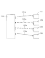
MU-MIMOの仕組みを、図8に示すシステムを例にして、以下に説明する。
なお、このシステムでは、ビームフォーマ100が同時にパラレルでデータを送ることができる数(ストリーム数)とビームフォーミ101、102、103、104が同数であるが、MU-MIMOはこれに限定されず、ストリーム数がビームフォーミ数より多いこともあるのは言うまでもない。
なお、このシステムでは、ビームフォーマ100が同時にパラレルでデータを送ることができる数(ストリーム数)とビームフォーミ101、102、103、104が同数であるが、MU-MIMOはこれに限定されず、ストリーム数がビームフォーミ数より多いこともあるのは言うまでもない。
ビームフォーマ100は、まず、ビームフォーミ101、102、103、104に送る各データを、ストリーム101a、102a、103a、104aそれぞれに割り当てる。次に、ビームフォーマ100は、ビームフォーマ100から発信されるデータに重み付けをするプリコーディングによって、それぞれのデータを発信前に予め処理して、ビームフォーミ101、102、103、104間で干渉を生じさせないようにする。
プリコーディングによるデータへの重み付けとは、ビームフォーマ100が、ビームフォーミ101、102、103、104のチャネル(伝送路)情報を基にして、ビームフォーミ101、102、103、104間で干渉を生じないようにする重み行列を求め、この重み行列をデータに乗算することを意味する。
そして、ビームフォーマ100は、プリコーディングを行った各データをビームフォーミ101、102、103、104にそれぞれ送信する。
そして、ビームフォーマ100は、プリコーディングを行った各データをビームフォーミ101、102、103、104にそれぞれ送信する。
ところで、複数の産業用ロボットが設置されている現場の多くにおいては、連続するタイムサイクルごとに、制御装置から複数の産業用ロボットに指令信号を含むデータを伝送する同期通信が採用されている。各産業用ロボットは、タイムサイクルごとに指令信号を受信することにより他の産業用ロボットと精密に連関して作動でき、複数の産業用ロボット全体の作業効率を高めることが可能である。
この同期通信は、産業用ロボットの設置現場に限らず、複数の機器が連関して作動する他の現場においても利用されている。
この同期通信は、産業用ロボットの設置現場に限らず、複数の機器が連関して作動する他の現場においても利用されている。
IEEE P802.11acTM/D4.0,October 2012,"Part 11:Wireless LAN Medium Access Control(MAC) and Physical Layer(PHY) specifications"
ここで、MU-MIMOの従来の設計思想(以下、「従来のMU-MIMO」とも言う)においては、ビームフォーマが通信状態のよいビームフォーミと優先的に通信を行いシステム全体で高スループットを維持しようとするため、通信状態が劣悪なビームフォーミは通信が滞った状態となる。即ち、従来のMU-MIMOでは、複数のビームフォーミ全てに通信機会の公平性を確保する点が重視されていない。
一方、同期通信の同期精度を上げるには、複数のビームフォーミの中で最も通信状態が悪い通信レベルを向上させることが重要である。
従って、MU-MIMOを同期精度の高い(例えば、数μsecオーダ)同期通信に適用するには、MU-MIMOにおいて、ビームフォーミの通信レベルの底上げが求められる。
一方、同期通信の同期精度を上げるには、複数のビームフォーミの中で最も通信状態が悪い通信レベルを向上させることが重要である。
従って、MU-MIMOを同期精度の高い(例えば、数μsecオーダ)同期通信に適用するには、MU-MIMOにおいて、ビームフォーミの通信レベルの底上げが求められる。
そして、MU-MIMOにおいて通信状態が劣悪となる典型的な例に、ビームフォーミ間でチャネルの相関が高い状況が挙げられる。例えば、ビームフォーミ間の距離が短く、チャネル状態が近似している際に、そのビームフォーミ間でチャネルの相関が高くなる。
以下、図8に示すシステムにおいて、ビームフォーミ101、102間でチャネルの相関が高い場合に起こる現象を説明する。なお、ビームフォーミ103、104は、他のビームフォーミとチャネルの相関が低いものとする。
以下、図8に示すシステムにおいて、ビームフォーミ101、102間でチャネルの相関が高い場合に起こる現象を説明する。なお、ビームフォーミ103、104は、他のビームフォーミとチャネルの相関が低いものとする。
ビームフォーミ101、102間でチャネルの相関が高いことにより、ビームフォーマ100は、ストリーム101aに割り当てたデータ、及び、ストリーム102aに割り当てたデータそれぞれから、ビームフォーミ101、102間で干渉を生じさせないような重み行列を求めることができない。
その結果、ビームフォーミ103、104がそれぞれ通信を完了しているのに対し、ビームフォーミ101、102は、その干渉の影響により、通信エラーが多発し、通信未完了の状態が継続する。
その結果、ビームフォーミ103、104がそれぞれ通信を完了しているのに対し、ビームフォーミ101、102は、その干渉の影響により、通信エラーが多発し、通信未完了の状態が継続する。
このため、ビームフォーマ100とビームフォーミ103、104それぞれの間では順調に通信が行われるが、ビームフォーマ100とビームフォーミ101、102それぞれの間では通信が滞ることになり、所定の精度の同期通信を行うことができない。
本発明は、かかる事情に鑑みてなされるもので、チャネルの相関が高いビームフォーミが安定的に通信を行うことができるMU-MIMOシステムとMU-MIMOの通信方法を提供することを目的とする。
本発明は、かかる事情に鑑みてなされるもので、チャネルの相関が高いビームフォーミが安定的に通信を行うことができるMU-MIMOシステムとMU-MIMOの通信方法を提供することを目的とする。
前記目的に沿う第1の発明に係るMU-MIMOシステムは、ビームフォーマが、複数のビームフォーミそれぞれに対応する複数のデータを、ストリームに割り当ててプリコーディングし、前記複数のビームフォーミそれぞれに送信するMU-MIMOシステムであって、複数の前記ビームフォーミ間でチャネルの相関が高くなっているビームフォーミグループごとに、該複数のビームフォーミそれぞれに対応する複数の前記データを一つにまとめたデータ群を、1つ又は複数の前記ストリームに割り当てる割り当て手段と、前記データ群をプリコーディングする演算手段と、プリコーディングされた前記データ群を該データ群に含まれる複数の前記データにそれぞれ対応する前記ビームフォーミに送信する送出手段とを備える。
ここで、チャネルの相関が高いとは、チャネルの相関によるビームフォーミのパケットエラー率、あるいは、符号誤り率が所定の値以上となるチャネルの相関レベルであることを意味する。
ここで、チャネルの相関が高いとは、チャネルの相関によるビームフォーミのパケットエラー率、あるいは、符号誤り率が所定の値以上となるチャネルの相関レベルであることを意味する。
第1の発明に係るMU-MIMOシステムにおいて、前記割り当て手段は、前記複数のビームフォーミそれぞれのチャネル状態から検出した該ビームフォーミ間のチャネルの相関を基にして、前記データ群にまとめる複数の前記データを決定するのが好ましい。
第1の発明に係るMU-MIMOシステムにおいて、前記ビームフォーミは産業用ロボットであり、前記ビームフォーマは前記産業用ロボットに指令信号を送る制御装置であるのが好ましい。
前記目的に沿う第2の発明に係るMU-MIMOの通信方法は、ビームフォーマが、複数のビームフォーミそれぞれに対応する複数のデータを、ストリームに割り当ててプリコーディングし、前記複数のビームフォーミにそれぞれ送信するMU-MIMOの通信方法において、複数の前記ビームフォーミ間でチャネルの相関が高くなっているビームフォーミグループごとに、該複数のビームフォーミそれぞれに対応する複数の前記データを一つにまとめたデータ群を、1つ又は複数の前記ストリームに割り当てる工程Aと、前記データ群をプリコーディングする工程Bと、プリコーディングされた前記データ群を、該データ群に含まれる複数の前記データそれぞれに対応する前記ビームフォーミに送信する工程Cとを有する。
第2の発明に係るMU-MIMOの通信方法において、前記データ群にまとめる複数の前記データを、前記複数のビームフォーミそれぞれのチャネル状態から検出した該ビームフォーミ間のチャネルの相関を基に決定するのが好ましい。
第1の発明に係るMU-MIMOシステム、及び、第2の発明に係るMU-MIMOの通信方法は、複数のビームフォーミ間でチャネルの相関が高くなっているビームフォーミグループごとに、複数のビームフォーミそれぞれに対応する複数のデータを一つにまとめたデータ群を、1つ又は複数のストリームに割り当て、データ群をプリコーディングし、プリコーディングされたデータ群を、データ群に含まれる複数のデータそれぞれに対応するビームフォーミに送信するので、チャネルの相関が高い複数のビームフォーミが、そのビームフォーミそれぞれに対応するデータを一つにまとめたデータ群の受信によって、そのビームフォーミに対応するデータを取得でき、安定的に通信を行うことが可能である。
続いて、添付した図面を参照しつつ、本発明を具体化した実施の形態につき説明し、本発明の理解に供する。
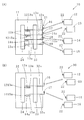
図1、図2に示すように、本発明の一実施の形態に係るMU-MIMOシステム10は、ビームフォーマ11が、複数のビームフォーミ12、13、14、15それぞれに対応する複数のデータ12a、13a、14a、15aを、ストリーム12s、13s、14s、15sに割り当ててプリコーディングし、複数のビームフォーミ12、13、14、15それぞれに送信する無線通信システムである。以下、詳細に説明する。
図1、図2に示すように、本発明の一実施の形態に係るMU-MIMOシステム10は、ビームフォーマ11が、複数のビームフォーミ12、13、14、15それぞれに対応する複数のデータ12a、13a、14a、15aを、ストリーム12s、13s、14s、15sに割り当ててプリコーディングし、複数のビームフォーミ12、13、14、15それぞれに送信する無線通信システムである。以下、詳細に説明する。
MU-MIMOシステム10は1つのビームフォーマ11を有し、そのビームフォーマ11は、図1、図2に示すように、複数の送受信用アンテナ16、17、18、19と、その複数の送受信用アンテナ16、17、18、19に接続された送受信処理回路20を備えている。
OSI参照モデルを含む複数のレイヤから構成された送受信処理回路20は、ビームフォーミ12、13、14、15それぞれに対して送信するデータ12a、13a、14a、15aを生成し、プリコーディング処理を行う。
OSI参照モデルを含む複数のレイヤから構成された送受信処理回路20は、ビームフォーミ12、13、14、15それぞれに対して送信するデータ12a、13a、14a、15aを生成し、プリコーディング処理を行う。
送受信処理回路20で生成されプリコーディングされたデータ12a、13a、14a、15aは、複数の送受信用アンテナ16、17、18、19及び図示しない複数のアンプを備える送出手段21を介して、ビームフォーミ12、13、14、15にそれぞれ送信される。
ビームフォーマ11と無線通信を行う複数のビームフォーミ12、13、14、15もそれぞれ、図示しないアンプに接続された送受信用アンテナ22を有し、ビームフォーマ11から送られたデータ12a、13a、14a、15aを受信する。
本実施の形態では、ビームフォーミ12、13、14、15はそれぞれ産業用ロボットであり、ビームフォーマ11は、ビームフォーミ12、13、14、15に指令信号を送る制御装置である。指令信号とは、ビームフォーミ12、13、14、15の動作を決定する信号を意味する。
ビームフォーマ11と無線通信を行う複数のビームフォーミ12、13、14、15もそれぞれ、図示しないアンプに接続された送受信用アンテナ22を有し、ビームフォーマ11から送られたデータ12a、13a、14a、15aを受信する。
本実施の形態では、ビームフォーミ12、13、14、15はそれぞれ産業用ロボットであり、ビームフォーマ11は、ビームフォーミ12、13、14、15に指令信号を送る制御装置である。指令信号とは、ビームフォーミ12、13、14、15の動作を決定する信号を意味する。
送受信処理回路20には、図2に示すように、ビームフォーミ12、13、14、15それぞれに対応した(供給すべき)データ12a、13a、14a、15aを生成するデータ処理手段23と、データ処理手段23で生成されたデータ12a、13a、14a、15aを複数のストリーム12s、13s、14s、15sに割り当てる(あてがう)割り当て手段24と、データ12a、13a、14a、15aをプリコーディングし送出手段21に与える演算手段25が設けられている。データ処理手段23、割り当て手段24及び演算手段25は、例えば、記憶媒体の中に格納されたプログラムである。
データ12a、13a、14a、15aはそれぞれ、ビームフォーミ12、13、14、15に対応する指令信号を含んだ所定長(本実施の形態では6バイト)のデジタル情報列である。
ビームフォーミ12は複数の動作パターンを行うことができ、各動作パターンに対して異なる指令信号が設けられている。データ12aを構成するデジタル情報列は、ビームフォーミ12の動作パターンごとに異なり、ビームフォーミ12はデータ12aのデジタル情報列に応じて所定の動作パターンを行う。この点、ビームフォーミ13とデータ13aの関係、ビームフォーミ14とデータ14aの関係、及び、ビームフォーミ15とデータ15aの関係も、ビームフォーミ12とデータ12aの関係とそれぞれ同じである。
ビームフォーミ12は複数の動作パターンを行うことができ、各動作パターンに対して異なる指令信号が設けられている。データ12aを構成するデジタル情報列は、ビームフォーミ12の動作パターンごとに異なり、ビームフォーミ12はデータ12aのデジタル情報列に応じて所定の動作パターンを行う。この点、ビームフォーミ13とデータ13aの関係、ビームフォーミ14とデータ14aの関係、及び、ビームフォーミ15とデータ15aの関係も、ビームフォーミ12とデータ12aの関係とそれぞれ同じである。
データ12a、13a、14a、15aは、まず、データ処理手段23により、予め定められた設定に従って生成され、データ処理手段23から割り当て手段24に与えられる。
割り当て手段24は、ビームフォーミ12、13、14、15のチャネル状態(情報)を、所定の時間間隔でビームフォーミ12、13、14、15からそれぞれ取得する。次に、割り当て手段24は、ビームフォーミ12、13、14、15の各チャネル状態を基にして、データ処理手段23から受け取ったデータ12a、13a、14a、15aそれぞれの割り当て先を、ストリーム12s、13s、14s、15sの中から選択する。
割り当て手段24は、ビームフォーミ12、13、14、15のチャネル状態(情報)を、所定の時間間隔でビームフォーミ12、13、14、15からそれぞれ取得する。次に、割り当て手段24は、ビームフォーミ12、13、14、15の各チャネル状態を基にして、データ処理手段23から受け取ったデータ12a、13a、14a、15aそれぞれの割り当て先を、ストリーム12s、13s、14s、15sの中から選択する。
複数のデータ12a、13a、14a、15aのストリーム12s、13s、14s、15sへの割り当ては、具体的には、以下のように行われる。
複数のビームフォーミ12、13、14、15がそれぞれ他のビームフォーミ12、13、14、15との関係でチャネルの相関が低い場合、複数のデータ12a、13a、14a、15aはそれぞれ別個のストリーム12s、13s、14s、15sに割り当てられる。本実施の形態では、データ12a、13a、14a、15aが、図2に示すように、ストリーム12s、13s、14s、15sにそれぞれ割り当てられる。
ここで、チャネルの相関が低いとは、チャネルの相関によるビームフォーミ12、13、14、15のパケットエラー率がX%(所定の値)未満となるチャネルの相関レベルを意味し、反対に、パケットエラー率がX%以上のチャネルの相関レベルはチャネルの相関が高いということになる。X%は、例えば、20~80%の範囲の値であり、この値は、MU-MIMOシステムを利用する現場で要求される通信レベルに応じて異なる。
複数のビームフォーミ12、13、14、15がそれぞれ他のビームフォーミ12、13、14、15との関係でチャネルの相関が低い場合、複数のデータ12a、13a、14a、15aはそれぞれ別個のストリーム12s、13s、14s、15sに割り当てられる。本実施の形態では、データ12a、13a、14a、15aが、図2に示すように、ストリーム12s、13s、14s、15sにそれぞれ割り当てられる。
ここで、チャネルの相関が低いとは、チャネルの相関によるビームフォーミ12、13、14、15のパケットエラー率がX%(所定の値)未満となるチャネルの相関レベルを意味し、反対に、パケットエラー率がX%以上のチャネルの相関レベルはチャネルの相関が高いということになる。X%は、例えば、20~80%の範囲の値であり、この値は、MU-MIMOシステムを利用する現場で要求される通信レベルに応じて異なる。
一方、割り当て手段24が、複数のビームフォーミ12、13、14、15の中に、他のビームフォーミ12、13、14、15との関係でチャネルの相関が高い(チャネルの相関によるパケットエラー率がX%以上となるチャネルの相関レベルである)ものを検出した場合、割り当て手段24は、チャネルの相関の高くなっている組み合わせを基に複数のビームフォーミ12、13、14、15を、1又は複数のビームフォーミグループにグループ分けする。そして、割り当て手段24は、ビームフォーミグループごとに、ビームフォーミグループに属する複数のビームフォーミそれぞれに対応する複数のデータを一つにまとめたデータ群をストリーム12s、13s、14s、15sに割り当てる。
なお、1つのデータ群は複数のデータを備えたデジタル情報列のかたまり(パケット)である。
なお、1つのデータ群は複数のデータを備えたデジタル情報列のかたまり(パケット)である。
割り当て手段が、複数のビームフォーミの中に、例えば、合計M組のチャネルの相関が高いビームフォーミの群を検出したとすると、割り当て手段は、チャネルの相関が高くなっている複数のビームフォーミをM個のビームフォーミグループにグループ分けし、M個のビームフォーミグループ各々に対して、ビームフォーミグループに属する複数のビームフォーミそれぞれに対応する複数のデータを一つにまとめたデータ群を、ストリームに割り当てる。
そして、K番目のビームフォーミグループにおいて、N個(Nは2以上の整数)のビームフォーミ間でチャネルの相関が高くなっているとすると、割り当て手段は、そのN個のビームフォーミそれぞれに対応するデータを1つにまとめたデータ群(以下、「データ群K」とも言う)を、1つ又は複数のストリームに割り当てる。データ群Kが割り当てられるストリームは、データ群Kに含まれるデータに対応するビームフォーミに対して割り当てられた(対応した)ストリームである。
そして、K番目のビームフォーミグループにおいて、N個(Nは2以上の整数)のビームフォーミ間でチャネルの相関が高くなっているとすると、割り当て手段は、そのN個のビームフォーミそれぞれに対応するデータを1つにまとめたデータ群(以下、「データ群K」とも言う)を、1つ又は複数のストリームに割り当てる。データ群Kが割り当てられるストリームは、データ群Kに含まれるデータに対応するビームフォーミに対して割り当てられた(対応した)ストリームである。
ここで、各ビームフォーミに1つのストリームが割り当てられている場合、割り当て手段は、データ群KをN個のストリームにそれぞれ割り当てる。
一方、各ビームフォーミがL(L≧2)個の送受信用アンテナを備え、各ビームフォーミにL個のストリームが割り当てられる場合、割り当て手段は、データ群Kを、(N×L)個のストリームにそれぞれ割り当てる。
なお、一つのビームフォーミに複数のストリームを対応させることで、ダイバーシチ(diversity)効果による通信の安定性向上を図れることは言うまでもない。
一方、各ビームフォーミがL(L≧2)個の送受信用アンテナを備え、各ビームフォーミにL個のストリームが割り当てられる場合、割り当て手段は、データ群Kを、(N×L)個のストリームにそれぞれ割り当てる。
なお、一つのビームフォーミに複数のストリームを対応させることで、ダイバーシチ(diversity)効果による通信の安定性向上を図れることは言うまでもない。
MU-MIMOシステム10においては、ビームフォーマ11が、ビームフォーミ12、13、14、15にストリーム12s、13s、14s、15sをそれぞれ割り当てて通信を行う。このMU-MIMOシステム10において、割り当て手段24が、ビームフォーミ12、13間でチャネルの相関が高く、ビームフォーミ14、15はそれぞれ、他のビームフォーミ12、13、14、15との関係でチャネルの相関が低いのを検出した場合、図3(A)に示すように、ビームフォーミ12、13間でチャネルの相関が高くなっているビームフォーミグループについて、データ12a、13aを一つにまとめたデータ群1213aを、ストリーム12s、13sにそれぞれ割り当てる。
データ14a、15aは、まとめられることなく、データ14aがストリーム14sに割り当てられ、データ15aがストリーム15sにそれぞれ割り当てられる。
因って、割り当て手段24は、複数のビームフォーミ12、13、14、15それぞれのチャネル状態から検出したビームフォーミ間のチャネルの相関を基にして、どのデータをデータ群として一つにまとめるかを決定し、更に、データ群にまとめるデータが存在する場合、そのデータ群にまとめる複数のデータを決定することになる。
なお、データ14a、15a及びデータ群1213aをストリームに割り当てるアルゴリズムとしては、最大チャネル容量選択法や、最大最小特異値法等の周知の方法を採用することができる。
因って、割り当て手段24は、複数のビームフォーミ12、13、14、15それぞれのチャネル状態から検出したビームフォーミ間のチャネルの相関を基にして、どのデータをデータ群として一つにまとめるかを決定し、更に、データ群にまとめるデータが存在する場合、そのデータ群にまとめる複数のデータを決定することになる。
なお、データ14a、15a及びデータ群1213aをストリームに割り当てるアルゴリズムとしては、最大チャネル容量選択法や、最大最小特異値法等の周知の方法を採用することができる。
そして、ストリーム12s、13sにそれぞれ割り当てられたデータ群1213aは、演算手段25によってプリコーディングされ、送受信用アンテナ16、17から発信され、ビームフォーミ12、13によってそれぞれ受信される。
ビームフォーミ12(ビームフォーミ13についても同じ)は、ビームフォーマ11から受け取ったプリコーディングされたデータ群1213aに含まれているデータ12a(ビームフォーミ13については、データ13a)を基に、次に行うべき動作パターンを決定する。
ビームフォーミ12(ビームフォーミ13についても同じ)は、ビームフォーマ11から受け取ったプリコーディングされたデータ群1213aに含まれているデータ12a(ビームフォーミ13については、データ13a)を基に、次に行うべき動作パターンを決定する。
ここで、ビームフォーミ12、13はチャネルの相関が高いため、ビームフォーミ12、13は共に、送受信用アンテナ16から発信されたプリコーディングされたデータ群1213aと、送受信用アンテナ17から発信されたプリコーディングされたデータ群1213aを受信することができる。
従って、ビームフォーミ12、13はそれぞれ、少なくとも送受信用アンテナ16、17のうち一方から発信されたデータ群1213aの受信に成功することで、次に行うべき動作パターンを決定可能なダイバーシチ効果を得られる状態にある。
従って、ビームフォーミ12、13はそれぞれ、少なくとも送受信用アンテナ16、17のうち一方から発信されたデータ群1213aの受信に成功することで、次に行うべき動作パターンを決定可能なダイバーシチ効果を得られる状態にある。
また、データ14a、15aは、演算手段25によりプリコーディングされ、ビームフォーマ11の送受信用アンテナ18、19から発信され、それぞれビームフォーミ14、15によって受信される。ビームフォーミ14、15はそれぞれ、プリコーディングされたデータ14a、15aを基に、次に行うべき動作パターンを決定する。
プリコーディングには、演算方法が異なるCI(Channel Inversion)、RCI(Regularized Channel Inversion)、及び、BD(Block Diagonalization)の各手法があり、本実施の形態では、プリコーディングの手法として、BDを採用しているが、これに限定されないのは言うまでもない。
プリコーディングには、演算方法が異なるCI(Channel Inversion)、RCI(Regularized Channel Inversion)、及び、BD(Block Diagonalization)の各手法があり、本実施の形態では、プリコーディングの手法として、BDを採用しているが、これに限定されないのは言うまでもない。
BD手法では、まず、ビームフォーミのチャネル状態を基に得られるチャネル行列Hを特異値分解することで重み行列WBDが生成され、この重み行列WBDをデータ(送信シンボル)uに乗算してプリコーディングが行われる。
データuと、データuをプリコーディングしたデータsは、以下の式1の関係にある。
データuと、データuをプリコーディングしたデータsは、以下の式1の関係にある。

正規化ゲインを1/√γBDとし、正規化後の送信信号をxとすると、ビームフォーマからビームフォーミに伝搬した信号である受信信号yBDは以下の式2で表される。なお、x=(1/√γBD)sである。式2において、HBDは、BD手法によるプリコーディングがなされたチャネル行列であり、具体的にはチャネル行列HにWBDを乗算したものであり、nは、熱雑音ベクトルである。
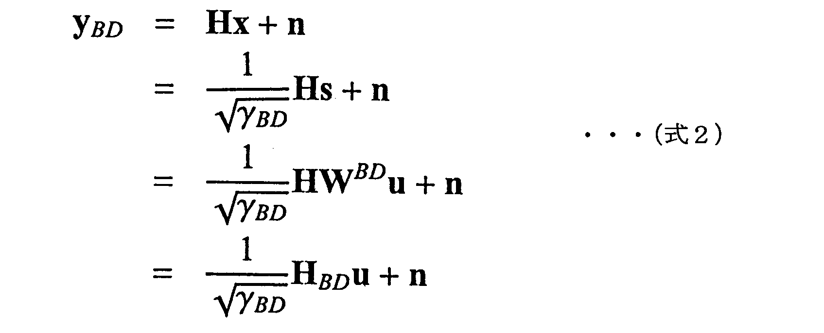
このとき、チャネルは以下の式3に示すチャネルHBDとして取り扱うことができる。ここで、Mkは、ビームフォーマの送受信アンテナからビームフォーミkの送受信アンテナへの行列を表す。
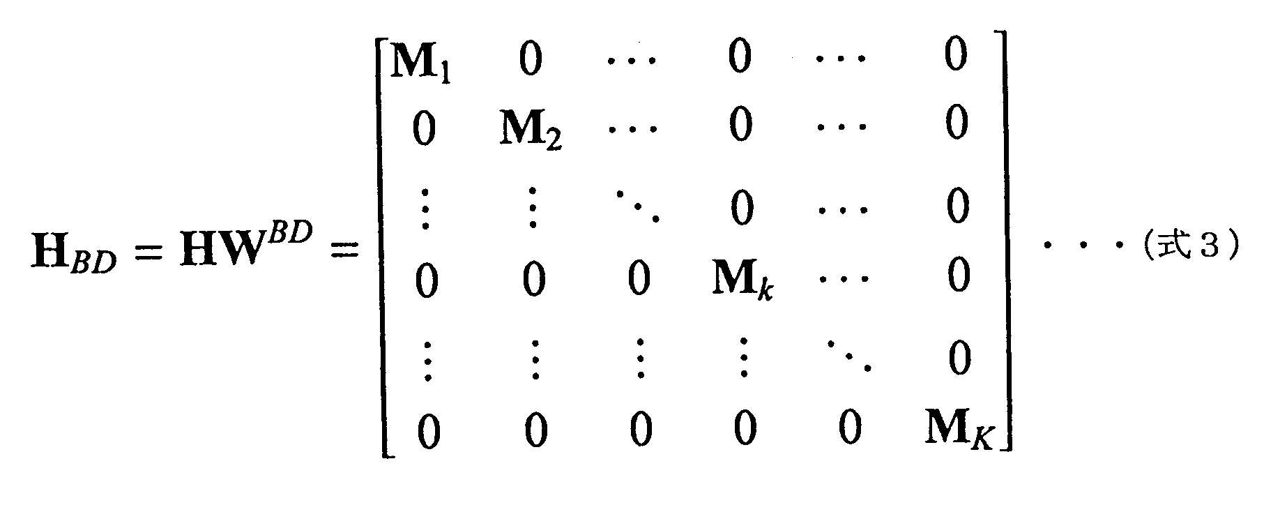
式3より、チャネル行列HBDは各ビームフォーミのチャネル行列M1、M2、・・・、Mk、・・・、MKで構成される部分対角行列となり、相関を生じる成分を除去、あるいは、減少した状態で、通信が行われる。
そして、重み行列WBDは、以下の式4で示すように、各ビームフォーミへの重み行列wkで構成されるため、各ビームフォーミごとの重み行列wkを求めることで、重み行列WBDを得ることできる。
そして、重み行列WBDは、以下の式4で示すように、各ビームフォーミへの重み行列wkで構成されるため、各ビームフォーミごとの重み行列wkを求めることで、重み行列WBDを得ることできる。

ビーフォーミkの重み行列の生成は、はじめに、チャネル行列Hからビーフォーミkのチャネル行列を除去したチャネル行列Hk’を得る。チャネル行列Hk’はビームフォーマの全ての送受信用アンテナからビームフォーミkを除くビームフォーミの送受信用アンテナへのチャネルを意味する。チャネル行列H及びチャネル行列Hk’は以下の式5及び式6でそれぞれ示される。

ここで、ビームフォーマの送受信用アンテナの数をNTX、1つのビームフォーミが備える送受信用アンテナの数をNRX、ビームフォーミの数をKとして、Hk’に特異値分解を適用すると、Hk’は以下の式7で表される。

Hk’は、NRX(K-1)×NTXの非正方行列であり、ランク落ちが生じない前提で、NRX×(K-1)個の特異値を持ち、Σk’と表される。それぞれの特異値に対する特異ベクトルをVk’とし、Hk’に、NTX-NRX(K-1)の零空間と零ベクトルVk”が存在するとすると、零ベクトルVk”をチャネル行列Hに乗算することで、ビームフォーミk以外のビームフォーミに対しヌルを向け相関成分を除去することが可能となる。全てのビームフォーミについて、特定のビームフォーミ以外のビームフォーミに対してヌルを向ける零ベクトルVk”を求めることで、以下の式8に示す重み行列WBDを得ることができる。

MU-MIMOシステム10において、ビームフォーミ12、13間、及び、ビームフォーミ14、15間でそれぞれ相関が高くなっていると、データ群1213aはストリーム12s、13sにそれぞれ割り当てられ、データ14a、15aを一つにまとめたデータ群1415aはストリーム14s、15sにそれぞれ割り当てられる。
このとき、ビームフォーミ12に対応するH1,2’は以下の式9で表される。
このとき、ビームフォーミ12に対応するH1,2’は以下の式9で表される。

H1,2’を特異値分解することで、ビームフォーミ12、13以外にヌルを向ける零ベクトルV1,2”が算出され、このV1,2”をビームフォーミ12、13に対する重み行列w1,2 とする。
この処理を、ビームフォーミ13、14、15について行うことにより、以下の式10で示される重み行列WBD2が生成される。
この処理を、ビームフォーミ13、14、15について行うことにより、以下の式10で示される重み行列WBD2が生成される。

重み行列WBD2は、4×2の行列であり、相関を生じる成分を除去したHWBD2は、以下の式11で表される。
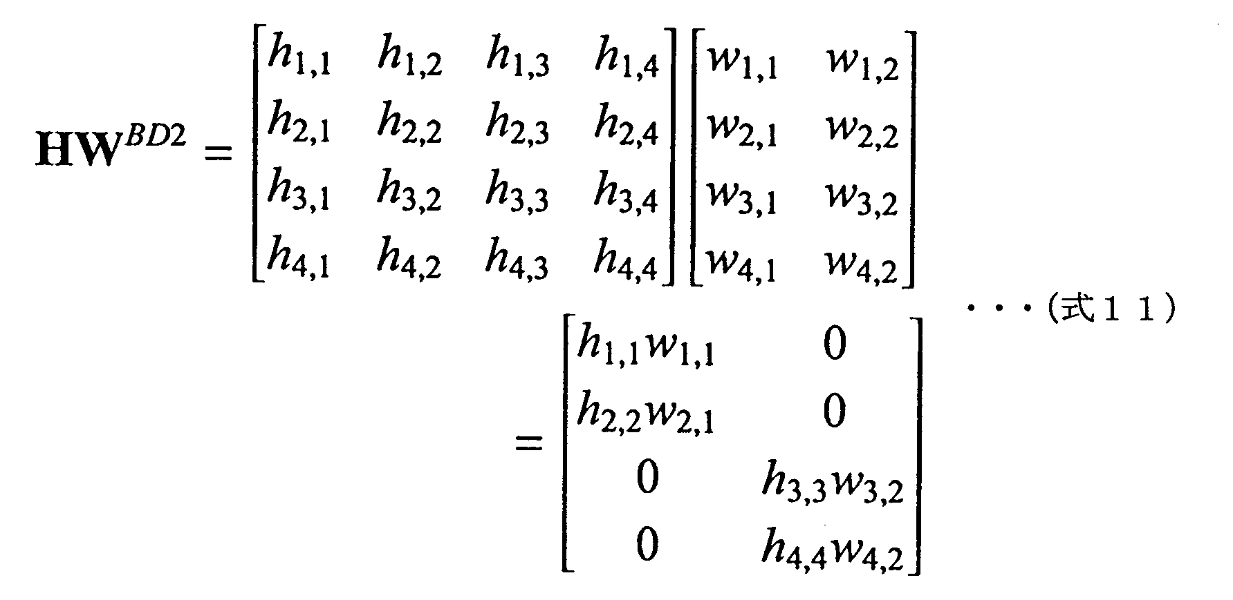
ここで、MU-MIMOシステム10においては、相関が高いビームフォーミ12、13に対し、同じデータ群1213aが送信されるので、ビームフォーミ12、13はそれぞれ、データ12、13を安定的に得ることができ、結果として、ビームフォーミ12、13間の高い相関による影響を抑制可能である。この点、ビームフォーミ14、15についても同じことが言える。
また、各ビームフォーミのチャネルの相関関係が固定されている現場では、複数のビームフォーミ間でチャネルの相関が高くなっているビームフォーミグループそれぞれに対し、1つのストリームを割り当てるようにしてもよい。
MU-MIMOシステム10の変形例である図3(B)に示すMU-MIMOシステム30は、ビームフォーミ12、13、14、15のチャネルの相関が固定されている。
以下、MU-MIMOシステム30について説明する。なお、MU-MIMOシステム10と同様の構成については、MU-MIMOシステム10と同一の符号を付して詳しい説明は省略する。
MU-MIMOシステム10の変形例である図3(B)に示すMU-MIMOシステム30は、ビームフォーミ12、13、14、15のチャネルの相関が固定されている。
以下、MU-MIMOシステム30について説明する。なお、MU-MIMOシステム10と同様の構成については、MU-MIMOシステム10と同一の符号を付して詳しい説明は省略する。
MU-MIMOシステム30においては、ビームフォーマ31及びビームフォーミ12、13、14、15の配置が固定され、ビームフォーミ12、13、14、15それぞれのチャネル状態が固定されている。本実施の形態では、ビームフォーミ12、13間でチャネルの相関が高く、ビームフォーミ14、15間でチャネルの相関が高い。
ビームフォーマ31が備える割り当て手段24は、ストリーム32s、33sそれぞれに割り当てるデータ群が定められた設定テーブルを有している。本実施の形態では、その設定テーブルに、データ12a、13aを一つにまとめたデータ群1213aをストリーム32sに割り当て、データ14a、15aを一つにまとめたデータ群1415aをストリーム33sに割り当てることが予め定められている。
ビームフォーマ31が備える割り当て手段24は、ストリーム32s、33sそれぞれに割り当てるデータ群が定められた設定テーブルを有している。本実施の形態では、その設定テーブルに、データ12a、13aを一つにまとめたデータ群1213aをストリーム32sに割り当て、データ14a、15aを一つにまとめたデータ群1415aをストリーム33sに割り当てることが予め定められている。
割り当て手段24は、設定テーブルに従い、ストリーム32sにデータ群1213aを割り当て、ストリーム33sにデータ群1415aを割り当てる。
そして、ストリーム32sに割り当てられたデータ群1213aは、ビームフォーマ31が備える演算手段25によりプリコーディングされ、送受信用アンテナ16からビームフォーミ12、13に送信される。ストリーム33sに割り当てられたデータ群1415aもデータ群1213aと同様に、演算手段25によりプリコーディングされ、送受信用アンテナ17からビームフォーミ14、15に送信される。
そして、ストリーム32sに割り当てられたデータ群1213aは、ビームフォーマ31が備える演算手段25によりプリコーディングされ、送受信用アンテナ16からビームフォーミ12、13に送信される。ストリーム33sに割り当てられたデータ群1415aもデータ群1213aと同様に、演算手段25によりプリコーディングされ、送受信用アンテナ17からビームフォーミ14、15に送信される。
従って、MU-MIMOシステム10では、ビームフォーマ11が複数のビームフォーミ12、13、14、15と同数の送受信用アンテナ16、17、18、19を備えていたのに対し、MU-MIMOシステム30においては、ビームフォーマ31が、複数のビームフォーミ12、13、14、15より少ない送受信用アンテナ16、17を備えることで無線通信を行うことができる。
ここまで記載したように、MU-MIMOシステムのシステム設計に応じて、割り当て手段は、複数のデータを一つにまとめたデータ群を1つ又は複数のストリームに割り当てることになる。
ここまで記載したように、MU-MIMOシステムのシステム設計に応じて、割り当て手段は、複数のデータを一つにまとめたデータ群を1つ又は複数のストリームに割り当てることになる。
なお、MU-MIMOシステム10は、4つのビームフォーミ12、13、14、15に対し4つのストリーム12s、13s、14s、15sにより無線通信を行うシステムであり、MU-MIMOシステム30は、4つのビームフォーミ12、13、14、15に対し2つのストリーム32s、33sで無線通信を行うシステムであるが、ビームフォーミの数や、ストリームの数はこれに限定されない。
次に、MU-MIMOシステム10に適用可能な本発明の一実施の形態に係るMU-MIMOの通信方法を、以下に説明する。
まず、割り当て手段は、所定の時間間隔で取得する複数のビームフォーミそれぞれのチャネル状態から検出したビームフォーミ間のチャネルの相関を基に、データ群にまとめる複数のデータを動的に決定する。
そして、割り当て手段は、決定した内容に従って、複数のビームフォーミ間でチャネルの相関が高くなっているビームフォーミグループごとに、複数のデータをデータ群にまとめ、その複数のデータを一つにまとめたデータ群を1つ又は複数のストリームに割り当てる(工程A)。
まず、割り当て手段は、所定の時間間隔で取得する複数のビームフォーミそれぞれのチャネル状態から検出したビームフォーミ間のチャネルの相関を基に、データ群にまとめる複数のデータを動的に決定する。
そして、割り当て手段は、決定した内容に従って、複数のビームフォーミ間でチャネルの相関が高くなっているビームフォーミグループごとに、複数のデータをデータ群にまとめ、その複数のデータを一つにまとめたデータ群を1つ又は複数のストリームに割り当てる(工程A)。
また、割り当て手段は、チャネルの相関がないビームフォーミに対応したデータを、データ群を割り当てたストリームとは別のストリームに割り当てる。
そして、演算手段は、ストリームに割り当てられたデータ群、及び、ストリームに割り当てられたデータをプリコーディングし(工程B)、それらを送出手段に与える。
送出手段は、プリコーディングされたデータ群を、そのデータ群に含まれる複数のデータそれぞれに対応するビームフォーミに送信すると共に、プリコーディングされたデータを、そのデータに対応するビームフォーミに送信する(工程C)。
そして、演算手段は、ストリームに割り当てられたデータ群、及び、ストリームに割り当てられたデータをプリコーディングし(工程B)、それらを送出手段に与える。
送出手段は、プリコーディングされたデータ群を、そのデータ群に含まれる複数のデータそれぞれに対応するビームフォーミに送信すると共に、プリコーディングされたデータを、そのデータに対応するビームフォーミに送信する(工程C)。
次に、本発明の作用効果を確認するために行った実施例について説明する。
本実施例では、IEEE802.11ac規格に準拠したシミュレータを用いて、1つのビームフォーマと4つのビームフォーミの通信をシミュレーションした。シミュレーション諸元を以下に記載する。
SNR[dB]:30~50(5刻み)
各ビームフォーミに対する総送信パケット数:1000
各ビームフォーミに対する総送信ビット数:8.0×10⁶
各ビームフォーミのアンテナ数:1
ビームフォーマのアンテナ数:4
変調方式:64QAM
符号比率:5/6
チャネルモデル:TGac Model B
プリコーディング手法:BD
ストリーム割り当てアルゴリズム:最大チャネル容量選択法
本実施例では、IEEE802.11ac規格に準拠したシミュレータを用いて、1つのビームフォーマと4つのビームフォーミの通信をシミュレーションした。シミュレーション諸元を以下に記載する。
SNR[dB]:30~50(5刻み)
各ビームフォーミに対する総送信パケット数:1000
各ビームフォーミに対する総送信ビット数:8.0×10⁶
各ビームフォーミのアンテナ数:1
ビームフォーマのアンテナ数:4
変調方式:64QAM
符号比率:5/6
チャネルモデル:TGac Model B
プリコーディング手法:BD
ストリーム割り当てアルゴリズム:最大チャネル容量選択法
ビームフォーミ1はビームフォーミ2とチャネルの相関が高い関係にあり、ビームフォーミ3、4は他のビームフォーミ1、2、3、4との関係でチャネルの相関が低い条件設定をし、ビームフォーミ1~4それぞれのBER(Bit Error Rate)をシミュレーションにより算出した。ストリームへのデータの割り当ては、1)ビームフォーミ1~4それぞれのデータをそれぞれ4つのストリームに割り当てる比較例の方法と、2)ビームフォーミ1、2のデータをまとめたデータ群を2つのストリームにそれぞれ割り当て、ビームフォーミ3のデータを他の1つのストリームに割り当て、ビームフォーミ4のデータを残りの1つのストリームに割り当てる実施例の方法とでそれぞれ行った。
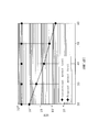
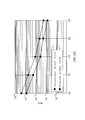
ビームフォーミ1~4それぞれについて、比較例の方法と実施例の方法の各シミュレーション結果を図4~図7のグラフに示す。なお、図4~図7で、User1、2、3、4は、それぞれビームフォーミ1、2、3、4を示し、Conventional methodは比較例の方法を表し、Proposed methodは実施例の方法を意味する。
シミュレーション結果より、ビームフォーミ1、2で、実施例の方法が、比較例の方法に比べ、BER特性が良くなり、通信の安定性が大幅に増すことが明らかとなった。比較例の方法では、ビームフォーミ1、2のいずれにおいても、BERが10-1以下になることはなく、これは、通信ができない状態であると考えられる。
シミュレーション結果より、ビームフォーミ1、2で、実施例の方法が、比較例の方法に比べ、BER特性が良くなり、通信の安定性が大幅に増すことが明らかとなった。比較例の方法では、ビームフォーミ1、2のいずれにおいても、BERが10-1以下になることはなく、これは、通信ができない状態であると考えられる。
また、ビームフォーミ3、4においても、実施例の方法で、比較例の方法に比べ、BER特性が良くなっている。これは、ビームフォーマの2つの送受信用アンテナで同じデータ群を送信することで、この2つのアンテナから異なるデータを送信するのに比較して、ビームフォーマの送受信用アンテナ間の相関が低減したことによるものと考えられる。
また、最大チャネル容量選択法の代わりに、最大最小特異値法を採用した場合も、同様のシミュレーション結果が得られることが確認されている。
また、最大チャネル容量選択法の代わりに、最大最小特異値法を採用した場合も、同様のシミュレーション結果が得られることが確認されている。
以上、本発明の実施の形態を説明したが、本発明は、上記した形態に限定されるものでなく、要旨を逸脱しない条件の変更等は全て本発明の適用範囲である。
例えば、ビームフォーミは産業用ロボットに限定されず、タブレット端末等の通信端末であってもよく、ビームフォーマも産業用ロボットの動作を制御する制御装置に限定されず、通信端末に信号を送信する基地局端末であってもよい。
例えば、ビームフォーミは産業用ロボットに限定されず、タブレット端末等の通信端末であってもよく、ビームフォーマも産業用ロボットの動作を制御する制御装置に限定されず、通信端末に信号を送信する基地局端末であってもよい。
10:MU-MIMOシステム、11:ビームフォーマ、12~15:ビームフォーミ、12a~15a:データ、12s~15s:ストリーム、16~19:送受信用アンテナ、20:送受信処理回路、21:送出手段、22:送受信用アンテナ、23:データ処理手段、24:割り当て手段、25:演算手段、30:MU-MIMOシステム、31:ビームフォーマ、32s、33s:ストリーム、1213a、1415a:データ群
Claims (5)
- ビームフォーマが、複数のビームフォーミそれぞれに対応する複数のデータを、ストリームに割り当ててプリコーディングし、前記複数のビームフォーミそれぞれに送信するMU-MIMOシステムであって、
複数の前記ビームフォーミ間でチャネルの相関が高くなっているビームフォーミグループごとに、該複数のビームフォーミそれぞれに対応する複数の前記データを一つにまとめたデータ群を、1つ又は複数の前記ストリームに割り当てる割り当て手段と、
前記データ群をプリコーディングする演算手段と、
プリコーディングされた前記データ群を該データ群に含まれる複数の前記データにそれぞれ対応する前記ビームフォーミに送信する送出手段とを備えることを特徴とするMU-MIMOシステム。 - 請求項1記載のMU-MIMOシステムにおいて、前記割り当て手段は、前記複数のビームフォーミそれぞれのチャネル状態から検出した該ビームフォーミ間のチャネルの相関を基にして、前記データ群にまとめる複数の前記データを決定することを特徴とするMU-MIMOシステム。
- 請求項1又は2記載のMU-MIMOシステムにおいて、前記ビームフォーミは産業用ロボットであり、前記ビームフォーマは前記産業用ロボットに指令信号を送る制御装置であることを特徴とするMU-MIMOシステム。
- ビームフォーマが、複数のビームフォーミそれぞれに対応する複数のデータを、ストリームに割り当ててプリコーディングし、前記複数のビームフォーミにそれぞれ送信するMU-MIMOの通信方法において、
複数の前記ビームフォーミ間でチャネルの相関が高くなっているビームフォーミグループごとに、該複数のビームフォーミそれぞれに対応する複数の前記データを一つにまとめたデータ群を、1つ又は複数の前記ストリームに割り当てる工程Aと、
前記データ群をプリコーディングする工程Bと、
プリコーディングされた前記データ群を、該データ群に含まれる複数の前記データそれぞれに対応する前記ビームフォーミに送信する工程Cとを有するMU-MIMOの通信方法。 - 請求項4記載のMU-MIMOの通信方法において、前記データ群にまとめる複数の前記データを、前記複数のビームフォーミそれぞれのチャネル状態から検出した該ビームフォーミ間のチャネルの相関を基に決定することを特徴とするMU-MIMOの通信方法。
Applications Claiming Priority (2)
| Application Number | Priority Date | Filing Date | Title |
|---|---|---|---|
| JP2013-178280 | 2013-08-29 | ||
| JP2013178280A JP6172670B2 (ja) | 2013-08-29 | 2013-08-29 | Mu−mimoシステムとmu−mimoの通信方法 |
Publications (1)
| Publication Number | Publication Date |
|---|---|
| WO2015029570A1 true WO2015029570A1 (ja) | 2015-03-05 |
Family
ID=52586148
Family Applications (1)
| Application Number | Title | Priority Date | Filing Date |
|---|---|---|---|
| PCT/JP2014/067004 Ceased WO2015029570A1 (ja) | 2013-08-29 | 2014-06-26 | Mu-mimoシステムとmu-mimoの通信方法 |
Country Status (2)
| Country | Link |
|---|---|
| JP (1) | JP6172670B2 (ja) |
| WO (1) | WO2015029570A1 (ja) |
Families Citing this family (1)
| Publication number | Priority date | Publication date | Assignee | Title |
|---|---|---|---|---|
| GB2573817B (en) * | 2018-05-18 | 2020-12-02 | Cambium Networks Ltd | Method and Apparatus for Interference Mitigation for a MU-MIMO wireless Communication network |
Citations (1)
| Publication number | Priority date | Publication date | Assignee | Title |
|---|---|---|---|---|
| JP2010028737A (ja) * | 2008-07-24 | 2010-02-04 | Nippon Telegr & Teleph Corp <Ntt> | 無線通信方法及び無線通信システム |
Family Cites Families (2)
| Publication number | Priority date | Publication date | Assignee | Title |
|---|---|---|---|---|
| JP2001203623A (ja) * | 2000-01-19 | 2001-07-27 | Oki Electric Ind Co Ltd | 基地局アンテナシステム |
| JP4350491B2 (ja) * | 2002-12-05 | 2009-10-21 | パナソニック株式会社 | 無線通信システム、無線通信方法、及び無線通信装置 |
-
2013
- 2013-08-29 JP JP2013178280A patent/JP6172670B2/ja active Active
-
2014
- 2014-06-26 WO PCT/JP2014/067004 patent/WO2015029570A1/ja not_active Ceased
Patent Citations (1)
| Publication number | Priority date | Publication date | Assignee | Title |
|---|---|---|---|---|
| JP2010028737A (ja) * | 2008-07-24 | 2010-02-04 | Nippon Telegr & Teleph Corp <Ntt> | 無線通信方法及び無線通信システム |
Non-Patent Citations (5)
| Title |
|---|
| CHENG WANG ET AL.: "Adaptive Downlink Multi-User MIMO Wireless Systems for Correlated Channels with Imperfect CSI", IEEE TRANSACTIONS ON WIRELESS COMMUNICATIONS, vol. 5, no. ISSUE:, September 2006 (2006-09-01), pages 2435 - 2446 * |
| MITSUTERU YOSHIDA ET AL.: "Study on user scheduling with fairness and correlation among the users", IEICE TECHNICAL REPORT, vol. 108, no. 249, 15 October 2008 (2008-10-15), pages 31 - 35 * |
| SATOSHI MORITA ET AL.: "A Study on Wireless Synchronous Communication System Using MU-MIMO for FA", THE INSTITUTE OF ELECTRONICS, INFORMATION AND COMMUNICATION ENGINEERS 2013 NEN TSUSHIN SOCIETY TAIKAI KOEN RONBUNSHU 1, 3 September 2013 (2013-09-03), pages 467 * |
| THERDKIAT APHICHARTSUPHAPKHAJORN ET AL.: "User Scheduling Algorithm with User grouping for Multi-user MIMO Downlink System utilizing Block Diagonalization", IEICE TECHNICAL REPORT, vol. 112, no. 351, 6 December 2012 (2012-12-06), pages 263 - 268 * |
| ZHANG CHENGWEN ET AL.: "Resource allocation with CCI suppression for multiuser MIMO-OFDM downlink in correlated channels", JOURNAL OF SYSTEMS ENGINEERING AND ELECTRONICS, vol. 19, no. ISSUE:, April 2008 (2008-04-01), pages 213 - 219 * |
Also Published As
| Publication number | Publication date |
|---|---|
| JP2015046839A (ja) | 2015-03-12 |
| JP6172670B2 (ja) | 2017-08-02 |
Similar Documents
| Publication | Publication Date | Title |
|---|---|---|
| CN114598366B (zh) | 一种通信方法、装置、芯片、存储介质及程序产品 | |
| CN109787668B (zh) | 通信方法、通信装置和系统 | |
| JP6860152B2 (ja) | 部分空間選択を伝送するためのシステム及び方法 | |
| US9553650B2 (en) | MU-MIMO implementation with configurable antenna system | |
| WO2014029368A1 (en) | Systems and methods for interference alignment in wi-fi | |
| US9634775B2 (en) | Method for configuring a reconfigurable antenna system | |
| WO2016124072A1 (en) | System and method for massive mimo communication | |
| JP2010534027A (ja) | ユーザの干渉除去能力に基づくアンテナ重みの計算 | |
| WO2015112883A1 (en) | System and method for early termination in iterative null-space directed singular value decomposition for mimo | |
| CN118523808A (zh) | 用于无线通信系统的电子设备、方法和存储介质 | |
| CN107534473B (zh) | 发送装置、接收装置、控制站、通信系统和发送预编码方法 | |
| CN112868188A (zh) | 电子设备、通信方法以及介质 | |
| KR20130114471A (ko) | 다중입력 다중출력 시스템에서 송신 전력을 할당하는 방법 및 장치 | |
| CN114978268A (zh) | 去蜂窝导频长度优化方法及装置 | |
| CN109842435A (zh) | 一种用于执行预编码的方法和装置 | |
| KR20160000222A (ko) | 다운링크 mu-mimo을 위한 반복적 간섭 정렬 방법 및 장치 | |
| JP6172670B2 (ja) | Mu−mimoシステムとmu−mimoの通信方法 | |
| CN109905155B (zh) | 一种基于内外级联预编码的干扰管理方法、无线通信系统 | |
| US11018744B2 (en) | Block-diagonalization based beamforming | |
| KR102215381B1 (ko) | 무선랜에서 이종의 간섭정렬 기법에 기초하여 무선 통신을 수행하는 방법 및 장치 | |
| JP5340344B2 (ja) | 通信装置及び通信方法 | |
| WO2011018824A1 (ja) | 無線通信システム、無線通信装置及び無線通信方法 | |
| CN106921421B (zh) | 蓝牙路由系统、蓝牙路由发送及接收方法 | |
| KR101817014B1 (ko) | 다중 빔 코드 분할 다중 접속 통신 방법 및 이를 수행하는 장치 | |
| CN106452676B (zh) | 一种多点协同传输的方法及相关设备 |
Legal Events
| Date | Code | Title | Description |
|---|---|---|---|
| 121 | Ep: the epo has been informed by wipo that ep was designated in this application |
Ref document number: 14840820 Country of ref document: EP Kind code of ref document: A1 |
|
| NENP | Non-entry into the national phase |
Ref country code: DE |
|
| 122 | Ep: pct application non-entry in european phase |
Ref document number: 14840820 Country of ref document: EP Kind code of ref document: A1 |