WO2015029331A1 - ロボット及びその制御方法 - Google Patents
ロボット及びその制御方法 Download PDFInfo
- Publication number
- WO2015029331A1 WO2015029331A1 PCT/JP2014/003975 JP2014003975W WO2015029331A1 WO 2015029331 A1 WO2015029331 A1 WO 2015029331A1 JP 2014003975 W JP2014003975 W JP 2014003975W WO 2015029331 A1 WO2015029331 A1 WO 2015029331A1
- Authority
- WO
- WIPO (PCT)
- Prior art keywords
- robot
- area
- unobserved
- region
- arm
- Prior art date
- Legal status (The legal status is an assumption and is not a legal conclusion. Google has not performed a legal analysis and makes no representation as to the accuracy of the status listed.)
- Ceased
Links
Images









Classifications
-
- B—PERFORMING OPERATIONS; TRANSPORTING
- B25—HAND TOOLS; PORTABLE POWER-DRIVEN TOOLS; MANIPULATORS
- B25J—MANIPULATORS; CHAMBERS PROVIDED WITH MANIPULATION DEVICES
- B25J19/00—Accessories fitted to manipulators, e.g. for monitoring, for viewing; Safety devices combined with or specially adapted for use in connection with manipulators
- B25J19/06—Safety devices
-
- G—PHYSICS
- G05—CONTROLLING; REGULATING
- G05D—SYSTEMS FOR CONTROLLING OR REGULATING NON-ELECTRIC VARIABLES
- G05D1/00—Control of position, course, altitude or attitude of land, water, air or space vehicles, e.g. using automatic pilots
- G05D1/02—Control of position or course in two dimensions
- G05D1/021—Control of position or course in two dimensions specially adapted to land vehicles
- G05D1/0268—Control of position or course in two dimensions specially adapted to land vehicles using internal positioning means
- G05D1/0274—Control of position or course in two dimensions specially adapted to land vehicles using internal positioning means using mapping information stored in a memory device
Definitions
- the present invention relates to a robot and a control method thereof.
- Patent Document 1 discloses a robot that can move an arm or the like closer to an object while recognizing the object.
- the robot calculates a recognition space that suppresses the intrusion of the arm based on the position information of the camera and the position information of the grasped object.
- the recognition space means a space that hinders recognition of the grasped object when the arm enters.
- the robot calculates an arm trajectory that avoids entering the recognition space, and controls the arm.
- the range that can be observed by a camera or the like is finite, some areas that cannot be observed remain. However, if the robot is not allowed to enter a region that is not recognized (observed) by the robot, the operation of the robot becomes limited, and the expected operation cannot be sufficiently performed. On the other hand, when a robot enters an area that the robot does not recognize (for example, when an arm is moved in the area), there is a possibility that the robot may come in contact with an obstacle or the like in the area.
- the present invention has been made on the basis of the above-described knowledge, and provides a robot capable of improving safety even when the robot is operated in an unobserved region and a control method thereof. Objective.
- the robot according to the first aspect of the present invention is a robot that operates while observing the surrounding environment, the environment information acquiring means for acquiring the environment information around the robot, and the environment information acquired by the environment information acquiring means.
- a control means for reducing the driving force of the robot is provided.
- a control method is a control method for a robot that operates while observing a surrounding environment, the step of acquiring the surrounding environment information of the robot, and the robot Determining whether it is operating in an unobserved area that has not been acquired, and, if determined to be operating in the unobserved area, reducing the driving force of the robot; It is characterized by comprising.
- FIG. 2 is an external configuration diagram of the robot according to Embodiment 1.
- FIG. 2 is an internal configuration diagram of a robot according to Embodiment 1.
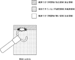
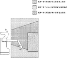
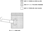
- FIG. It is a figure which shows an example of the environment which the robot which concerns on Embodiment 1 observes. It is a figure which shows the result of having observed the environment shown in FIG. 3 by the robot. It is a figure which shows the information used as a result of having observed the environment shown in FIG. It is a figure which shows the example which a robot operate
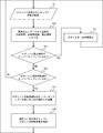
- FIG. 3 is a flowchart showing the operation of the robot according to the first embodiment. It is a figure which shows the overlap part of an arm and an unobserved area
- FIG. 6 is a flowchart showing the operation of the robot according to the second embodiment.
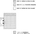
- FIG. 10 is a diagram illustrating an example of operation in each region of the robot according to the third embodiment. 10 is a flowchart showing the operation of the robot according to the third embodiment. It is a figure which shows the overlap part of a robot main body and an unobserved area
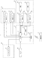
- FIG. 6 is an internal configuration diagram of a robot according to a fourth embodiment. 10 is a flowchart showing the operation of the robot according to the fourth embodiment.
- FIG. 1 is an external configuration diagram of the robot 1 according to the first embodiment.
- the robot 1 has a robot body 10, a moving carriage 20, an arm 30, and a head 40.
- the robot 1 is typically a life support robot for executing a work performed by a person at home instead of the person. For example, the robot 1 moves to an arbitrary place, picks up an object, delivers it to a person, and opens a window.
- the upper part of the movable carriage 20 is connected to the lower part of the robot body 10 so as to support the robot body 10 above it.
- the movable carriage 20 moves the robot 1 by driving wheels (not shown) provided in the lower part thereof.
- the arm 30 is connected to the front part of the robot body 10 so as to protrude forward of the robot body 10.
- the arm 30 is an articulated arm.
- the arm 30 includes a grip (gripping part) 6 capable of gripping an arbitrary object at a tip part thereof. Thereby, the robot 1 can move the grip 60 to a desired position by adjusting the angle of each joint of the arm 30, and can grip an object existing at that position.
- the head 40 is connected to the upper part of the robot body 10 so as to be supported by the robot body 10 above the robot body 10.
- a sensor 50 is attached to the front of the head 40 so that the front of the head 40 can be observed by the sensor 50.
- the sensor 50 is a sensor that observes the environment around the robot 1 and acquires environment information indicating the observed environment.
- the sensor 50 is typically a three-dimensional distance sensor that can observe the distance from the robot 1 to objects around the robot 1.
- an arbitrary one of various methods such as an optical method, an ultrasonic method, and a laser beam method may be used.
- the means for acquiring environmental information as the sensor 50 is not limited to a three-dimensional distance sensor.
- a camera may be provided as the sensor 50, and image information indicating an image captured by the camera may be acquired as environment information.
- the sensor 50 has a measurable angle range limited to a predetermined angle.
- the connecting portion between the head 40 and the robot body 10 has a multi-degree-of-freedom joint structure so that the head 40 can be operated. For example, by having at least two degrees of freedom as the joint structure, the head 40 can be moved up and down and left and right. Thereby, even if the angle range in which the sensor 50 can be measured is limited, it is possible to observe a wide range by operating the head 40.
- the operation terminal 9 is an information processing terminal that can communicate with the robot 1 wirelessly or by wire.
- the operation terminal 9 may be a stationary information processing terminal such as a desktop PC, but is preferably a portable information processing terminal so that the user can operate the robot 1 without restriction in the living space. There should be.
- the portable information processing terminal is a smartphone or a tablet terminal.
- the user can instruct the robot 1 through the operation terminal 9 to perform a work performed by a person as described above.
- the robot 1 executes the work instructed by the user on behalf of the user. In this way, the user's life is supported by the robot 1.
- the robot 1 observes the environment around the robot 1 with the sensor 50 and performs an action avoiding obstacles in the observed environment when performing the work instructed by the user.
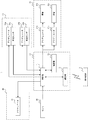
- FIG. 2 is an internal configuration diagram of the robot 1 according to the first embodiment.
- the robot 1 includes a control unit 11, a storage unit 12, a communication unit 13, actuators 21a and 21b, wheels 22a and 22b, actuators 31a and 31b, angle sensors (potentiometers) 32a and 32b, and an actuator 41.
- the control unit 11, the storage unit 12, and the communication unit 13 are included in the robot body 10.
- the actuators 21 a and 21 b and the wheels 22 a and 22 b are included in the moving carriage 20.
- Actuators 31 a and 31 b and angle sensors 32 a and 32 b are included in arm 30.
- the actuator 41 is included in the head 40.
- the control unit 11 controls the robot 1 in an integrated manner.
- the control unit 11 has a CPU (Central Processing Unit), and the CPU executes various programs as the control unit 11 by executing a program stored in the storage unit 12. That is, this program includes code for causing the CPU of the control unit 11 to execute various processes as the control unit 11.
- CPU Central Processing Unit
- the storage unit 12 stores the above program and various information used by the other control unit 11.
- storage part 12 contains at least 1 of the memory
- the communication unit 13 converts information output from the control unit 11 to be transmitted to the operation terminal 9 into a radio signal and transmits it to the operation terminal 9.
- the communication unit 13 converts the radio signal received from the operation terminal 9 into an electrical signal so as to be information that can be processed by the control unit 11, and outputs the electrical signal to the control unit 11.
- Actuators 21a and 21b drive the wheels 22a and 22b of the robot 1.
- Actuator 21a is driven by control from control part 11, and rotates wheel 22a.
- Actuator 21b is driven by control from control part 11, and rotates wheel 22b.
- the wheel 22a and the wheel 22b correspond to the wheel attached to the lower part of the moving carriage 20 described above. That is, the control unit 11 controls the actuators 21a and 21b to move the robot 1 by rotating the wheels 22a and 22b.
- Actuators 31 a and 31 b drive the arm 30 of the robot 1.
- Each of the actuators 31 a and 31 b is provided as a joint of the arm 30.
- the arm 30 has two joints of the actuator 31a and the actuator 31b will be described, but the number of joints of the arm 30 is not limited to this.
- Each of the angle sensors 32 a and 32 b is a sensor that detects the angle of each joint of the arm 30.
- the angle sensor 32a is attached to the actuator 31a and detects the angle of the actuator 31a.
- the angle sensor 32 a outputs an angle signal indicating the detected angle to the control unit 11.
- the angle sensor 32b is attached to the actuator 31b and detects the angle of the actuator 31b.
- the angle sensor 32 b outputs an angle signal indicating the detected angle to the control unit 11. Thereby, the control part 11 becomes possible [recognizing the state of the arm 30 based on the angle which the angle signal output from each of the angle sensors 32a and 32b shows].
- Actuator 41 drives the head 40 of the robot 1.
- the actuator 41 may be capable of moving the head 40 up and down and left and right, for example, as an actuator having multiple degrees of freedom (a predetermined degree of freedom of two or more degrees of freedom).
- a plurality of actuators 41 for driving the head 40 may be provided so that the head 40 can be driven with multiple degrees of freedom.
- the actuator 41 may have only one actuator with one degree of freedom so that the head 40 operates only up and down or left and right.
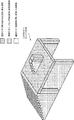
- FIG. 3 is a diagram illustrating an example of an environment observed by the robot 1 according to the first embodiment.
- FIG. 3 an example in which the robot 1 observes an environment where a quadrangular prism object is placed on a desk will be described.
- this environment as shown in FIG. 3, it is assumed that the robot 1 observes the environment with the sensor 50 from diagonally above the front of one side of the desk.
- the robot 1 classifies the space around the robot 1 as the observed environment into one of the following three areas. Prohibited area: Area where an obstacle can be observed Unobserved area: Uncertain area where it is not possible to observe whether there is an obstacle Free area: Area where an obstacle can be observed
- the control unit 11 determines an area that is observed by the sensor 50 in the space around the robot 1 and that detects an obstacle as a prohibited area. For example, the control unit 11 determines, in the depth direction with respect to the sensor 50, an area that is within a predetermined distance from the position where the obstacle is detected as a prohibited area. Thereby, for example, a certain range from the front surface (side surface on the sensor 50 side) and the upper surface of the quadrangular prism object, the top plate of the desk, and the front foot are determined as the prohibited areas.
- the control unit 11 determines an area that is not observed by the sensor 50 in the space around the robot 1 as an unobserved area. Therefore, the region not observed by the sensor 50 includes, for example, a region that is further in the depth direction with respect to the sensor 50 than the prohibited region. As a result, for example, a region (including a foot on the opposite side of the front) that is behind the foot on the square column, the desk top, and the front side of the sensor 50 is determined as an unobserved region. In addition, the determination result is maintained about the area
- the control unit 11 determines, as a free area, an area that is observed by the sensor 50 in the space around the robot 1 and no obstacle is detected. For example, the control unit 11 determines a space up to a position where an obstacle is detected as a free region. Thereby, for example, the space from the robot 1 (sensor 50) to the square pole, the desk, and other objects (wall, floor, etc.) is determined as a free region.
- the control unit 11 stores, in the storage unit 12, information indicating which of the above three classifications each region obtained by dividing the space around the robot 1 is stored in the storage unit 12.
- a three-dimensional array may be prepared in the storage unit 12 as spatial information.
- each element of the three-dimensional array corresponds to each of the regions obtained by dividing the space around the robot 1 into a lattice shape.
- a value indicating the classification as a determination result is stored in the corresponding element of the three-dimensional array. This value may be determined in advance as long as it is a value that can uniquely identify any of the prohibited region, the unobserved region, and the free region.
- control unit 11 when the control unit 11 tries to enter the certain area among the plurality of areas obtained by dividing the space around the robot 1, the control unit 11 refers to the value corresponding to the area of the spatial information. It can be recognized whether the area is one of a prohibited area, an unobserved area, and a free area.
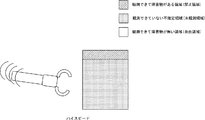
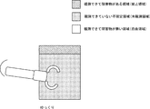
- FIG. 6A is a diagram showing an operation in the free region of the robot 1 according to the first embodiment.
- FIG. 6B is a diagram illustrating an operation in the unobserved region of the robot 1 according to the first embodiment.
- FIG. 6C is a diagram illustrating an operation in the prohibited area of the robot 1 according to the first embodiment.
- the control unit 11 when it is determined that all of the arms 30 are operating in the free region, the control unit 11 operates the arms 30 at a high speed. As shown in FIG. 6B, when it is determined that at least a part of the arm 30 is operating in the unobserved region (including the case where the arm 30 contacts the unobserved region), the control unit 11 The arm 30 is moved at a lower speed than when the 30 is operating in the free region. As illustrated in FIG. 6C, when it is determined that at least a part of the arm 30 is operating in the prohibited area (including the case where the arm 30 contacts the prohibited area), the control unit 11 may Stop completely.
- the arm 30 may come into contact with an object that the robot 1 cannot recognize by changing the speed of the arm 30 depending on whether or not the region in which the arm 30 operates has been observed. In some unobserved areas, the speed of the arm 30 is reduced. Thereby, even if the arm 30 is in contact with an object, the influence on the object can be reduced. Further, since the speed is not reduced more than necessary in the free area, the robot 1 can be operated at high speed.
- FIG. 7A is a diagram showing an operation in the free region of the robot 1 according to the first embodiment.
- FIG. 7B is a diagram showing an operation in the unobserved region of the robot 1 according to the first embodiment.
- FIG. 7C is a diagram illustrating an operation in the prohibited area of the robot 1 according to the first embodiment.
- the arms 30 are moved at a high speed.
- the speed is decreased according to the degree of the approach.
- the arm 30 is stopped.
- FIG. 8 is a flowchart showing the operation of the robot 1 according to the first embodiment.
- the robot 1 observes the environment around the robot 1 with the sensor 50 mounted on the robot 1 (S1). Specifically, the sensor 50 observes the environment around the robot 1, generates environment information indicating the observed environment, and outputs the environment information to the control unit 11. For example, when the sensor 50 is a three-dimensional distance sensor, the sensor 50 outputs information indicating the distance to the obstacle in each direction to the control unit 11 as environment information.
- the robot 1 divides the space around the robot 1 from the observed data into a free area, an unobserved area, and a prohibited area (S2). Specifically, the control unit 11 determines an area where an obstacle exists (prohibited area) and an area where an obstacle does not exist (free area) based on the environment indicated by the environmental information output from the sensor 50. . The control unit 11 updates the spatial information stored in the storage unit 12 according to the determination result. For example, each area indicated by the spatial information indicates an unobserved area as an initial value. Then, in the spatial information, the control unit 11 changes the area determined as the prohibited area to indicate the prohibited area, and changes the area determined as the free area to indicate the free area.
- the robot 1 determines whether the robot 1 and the prohibited area overlap (S3). Specifically, the control unit 11 calculates a region including the arm 30 in the space around the robot 1. For example, information indicating the shape of each component of the arm 30 such as the link (the portion between the joints of the arm 30) and the grip 60 is stored in the storage unit 12 in advance. The control unit 11 indicates the position of the robot 1, the shape of each component of the arm 30 indicated by the information stored in the storage unit 12, and the angle signal output from each of the angle sensors 32 a and 32 b of the arm 30. Based on the joint angle, a region including the arm 30 in the space around the robot 1 is calculated. Then, when it is determined that the region calculated as the region including the arm 30 is a prohibited region based on the spatial information, the control unit 11 determines that the robot 1 and the prohibited region overlap.
- the control unit 11 determines that the robot 1 and the prohibited region overlap.
- the position (current position) of the robot 1 may be specified by an arbitrary method.
- the control unit 11 may specify the current position of the robot 1 from the relative positions from obstacles around the robot 1 based on the environment information.
- an angle sensor is provided for each of the actuators 21a and 21b, and the total rotation angle from the reference position of the predetermined robot 1 based on the angle of the actuators 21a and 21b detected by the angle sensor (the wheel has rotated).
- the current position of the robot 1 may be specified based on the calculated total rotation angle and wheel size.
- the robot 1 stops its operation for a certain time (S4). Specifically, the control unit 11 calculates a command value for each of the actuators 31 a and 31 b so as to stop the operation of the arm 30. In other words, the control unit 11 calculates command values for the actuators 31a and 31b so that the angular velocities of the actuators 31a and 31b become zero. The control unit 11 outputs the calculated command value to each of the actuators 31a and 31b. Each of the actuators 31 a and 31 b stops the rotation of the joint of the arm 30 according to the command value output from the control unit 11. That is, the operation of the arm 30 is stopped.
- step S4 After the execution of step S4 is completed, the process returns to step S1. That is, the robot 1 stops the operation for a certain time, and then executes the process from step S1. For example, when an obstacle in the prohibited area that is determined to overlap with the robot 1 is an operating object (for example, a person or an animal), the area disappears from the prohibited area after a certain period of time. 1 may be operational. Therefore, by such processing, the latest state of the space around the robot 1 is observed, and when it is operable, the operation of the robot 1 can be resumed.
- an operating object for example, a person or an animal
- the robot 1 determines whether or not the robot 1 and the unobserved area overlap (S5). Specifically, the control unit 11 calculates a region including the arm 30 in the space around the robot 1. For example, the control unit 11 calculates a region including the arm 30 in the space around the robot 1 as in step S3 described above. Then, when it is determined that the region calculated as the region including the arm 30 is an unobserved region based on the spatial information, the control unit 11 determines that the robot 1 and the unobserved region overlap. To do. In addition, you may make it utilize the area
- the robot 1 calculates the volume S of the partial RUM where the robot 1 and the unobserved area overlap (S6). .
- the control unit 11 is output from the position of the robot 1, the shape of each component of the arm 30 indicated by the information stored in the storage unit 12, and the angle sensors 32 a and 32 b of the arm 30. Based on the joint angle indicated by the angle signal and the unobserved region indicated by the spatial information stored in the storage unit 12, the volume S of the partial RUM where the arm 30 and the unobserved region overlap as shown in FIG. calculate.
- the robot 1 limits the speed of the arm 30 so as to be inversely proportional to the calculated volume S (S7).
- the control unit 11 calculates a command value for each of the actuators 31a and 31b so that the speed of the arm 30 decreases as the calculated volume S increases.
- the control unit 11 calculates command values for the actuators 31a and 31b so that the angular velocities of the actuators 31a and 31b decrease as the calculated volume S increases.
- the control unit 11 outputs the calculated command value to each of the actuators 31a and 31b.
- Each of the actuators 31 a and 31 b rotates the joint of the arm 30 at a speed according to the command value output from the control unit 11.
- the arm 30 operates at a speed inversely proportional to the volume S.
- the process returns to step S1. That is, the robot 1 does not limit the speed of the arm 30.
- the control unit 11 calculates a command value for each of the actuators 31 a and 31 b so as not to limit the speed of the arm 30. In other words, the control unit 11 calculates command values for the actuators 31a and 31b so as not to limit the angular velocities of the actuators 31a and 31b.
- the control unit 11 outputs the calculated command value to each of the actuators 31a and 31b.
- Each of the actuators 31 a and 31 b rotates the joint of the arm 30 at a speed according to the command value output from the control unit 11.
- the arm 30 operates at an unrestricted speed. That is, this speed is higher than the speed of the arm 30 when it is determined that the robot 1 and the unobserved region overlap.
- the present invention is not limited to the above-described content itself, and may be changed as appropriate without departing from the spirit of the present invention.
- the degree of decrease in the speed of the arm 30 is increased as the volume S of the portion RUM where the arm 30 and the unobserved region overlap as shown in FIG. 9 increases (S6).
- S7) is not limited to this as long as the speed is limited when the arm 30 and the unobserved region overlap.
- the speed of the arm 30 is set to the first speed, and when the arm 30 and the unobserved area overlap, the speed of the arm 30 is set.
- the second speed may be lower than the first speed.
- the speed of the arm 30 may be a constant speed regardless of the volume S of the partial RUM where the arm 30 and the unobserved region overlap. Further, when the volume S of the partial RUM where the arm 30 and the unobserved region overlap with each other exceeds a predetermined threshold, the speed of the arm 30 may be set to the second speed. Further, the degree of decrease in the speed of the arm 30 may be increased as the distance between the arm 30 and the prohibited area becomes shorter.
- the operation of the arm 30 is stopped (S4).
- the arm 30 and the unobserved area overlap. If the speed of the arm 30 is further decreased, the arm 30 is not limited to being completely stopped (set to speed 0). That is, when it is determined that the arm 30 and the prohibited region overlap, the control unit 11 operates the arm 30 at a lower speed than when the arm 30 and the unobserved region overlap.
- the actuators 31a and 31b may be controlled.
- the operation of the arm 30 is stopped (S4).
- other operations may be performed instead.
- other operations may be executed.
- the control unit 11 determines that the arm 30 overlaps the prohibited area instead of stopping the operation of the arm 30.
- the actuators 31a and 31b may be controlled so that the arm 30 is returned to the state before the operation.
- the robot 1 is provided with a sound output device such as a speaker, and an alarm sound is output from the sound output device to notify the user that the arm 30 and the prohibited area overlap. You may make it do.
- the robot 1 may be provided with a light emitting device such as an LED, and the user may be notified that the robot 1 and the prohibited area overlap by causing the light emitting device to emit light.
- the robot 1 is provided with a display device such as a liquid crystal display or an organic EL display, and the alarm image is displayed on the display device so that the arm 30 and the prohibited area overlap each other. You may make it notify.
- the control unit 11 may keep the operation of the arm 30 stopped. Further, the control unit 11 may operate the arm 30 again when receiving an operation resumption instruction from the user via the operation terminal 9. Specifically, when the operation terminal 9 receives an input for instructing operation resumption from an input device such as a touch panel from a user, the operation terminal 9 generates a wireless signal instructing operation resumption and transmits the signal to the robot 1.
- the communication unit 13 of the robot 1 converts the radio signal received from the operation terminal 9 into an electric signal, and outputs it to the control unit 11 as information for instructing the operation resumption.
- the control unit 11 operates the arm 30 again in response to the output of information instructing operation resumption from the communication unit 13.
- the environment information cannot be acquired by the sensor 50 (environment information acquisition unit) that acquires the environment information around the robot 1 and the environment information acquisition unit.
- a control unit 11 control means that reduces the driving force of the robot 1 is provided.
- the robot 1 has spatial information (region information) indicating which of the regions around the robot 1 is an unobserved region, a prohibited region, and a free region. Is provided with a storage unit 12 (storage means). Then, the control unit 11 determines, based on the environmental information acquired by the sensor 50, which of the unobserved area, the prohibited area, and the free area is the area around the robot 1. The spatial information is updated according to the determination result, and it is determined based on the spatial information whether the region in which the robot 1 is operated is an unobserved region, a prohibited region, or a free region. I am doing so.
- the robot 1 can operate while avoiding the obstacle that has been observed by the sensor 50 in the past. Therefore, the safety when the robot 1 operates can be further improved.
- the driving force of the robot 1 is increased so that the controller 11 increases the degree of decrease in the driving force of the robot 1 as the volume of the robot 1 included in the unobserved region increases. Try to decrease.
- the driving force of the robot 1 can be reduced more greatly as the probability that the robot 1 enters the unobserved area more greatly and comes into contact with an obstacle increases. Therefore, the safety when the robot 1 operates can be further improved.
- the configuration of the robot 2 according to the second embodiment is the same as the configuration of the robot 1 according to the first embodiment described with reference to FIGS. 1 and 2, the description thereof is omitted.
- the operation of the control unit 11 is partially different in order to realize the control by the above-described method.
- the control unit 11 performs feedback control on the arm 30 of the robot 2. According to the configuration described above, the control unit 11 performs feedback control (for example, position control or speed control) based on the angles detected by the angle sensors 32a and 32b as feedback control. However, the type of feedback control is not limited to this. The control unit 11 may perform arbitrary feedback control among various feedback controls such as position control, speed control, and torque control.
- feedback control for example, position control or speed control
- the control unit 11 may perform arbitrary feedback control among various feedback controls such as position control, speed control, and torque control.
- the control unit 11 determines the respective angles of the actuators 31a and 31b indicated by the angle signals output from the angle sensors 32a and 32b and the target angles of the actuators 31a and 31b. Based on the deviation and the gain, a command value for each of the actuators 31a and 31b is generated and output to each of the actuators 31a and 31b.
- the control part 11 differentiates each angle of actuator 31a, 31b which the angle signal output from angle sensor 32a, 32b shows, and each of actuator 31a, 31b is each differentiated. Calculate angular velocity.
- the controller 11 generates a command value for each of the actuators 31a and 31b based on the calculated angular velocities of the actuators 31a and 31b, the deviations of the target angular velocities of the actuators 31a and 31b, and the gain, and the actuator 31a. , 31b.
- the robot 2 is provided with an angular velocity sensor (tacho generator) that detects the angular velocity of the actuators 31a and 31b and outputs an angular velocity signal indicating the detected angular velocity to the control unit 11. Also good. Then, the control unit 11 may use the angular velocities of the actuators 31a and 31b indicated by the angular signals output from the angular velocity sensor, instead of the angular velocities of the actuators 31a and 31b calculated from the angles.
- angular velocity sensor tilt generator
- the torque of the actuators 31a and 31b is detected for each of the actuators 31a and 31b, and a torque sensor that outputs a torque signal indicating the detected torque to the control unit 11 is provided as the robot 2. Be prepared for. And the control part 11 is based on the deviation of each target torque of each actuator 31a, 31b and each actuator 31a, 31b which the torque signal output from a torque sensor shows, and the gain of actuators 31a, 31b. A command value for each is generated and output to each of the actuators 31a and 31b.
- FIG. 10A is a diagram illustrating an operation in the free region of the robot 2 according to the second embodiment.
- FIG. 10B is a diagram illustrating an operation in the unobserved region of the robot 2 according to the second embodiment.
- FIG. 10C is a diagram illustrating an operation in the prohibited area of the robot 2 according to the second embodiment.
- the control unit 11 when it is determined that all of the arms 30 are operating in the free region, the control unit 11 feedback-controls the arms 30 with a high gain.
- the control unit 11 when it is determined that at least a part of the arm 30 is operating in the unobserved region (including the case where the arm 30 contacts the unobserved region), the control unit 11 The arm 30 is feedback-controlled with a lower gain than when the 30 is operating in the free region.
- the control unit 11 may The arm 30 is feedback-controlled with a lower gain than when operating in the unobserved region.
- the robot 2 when the robot 2 is operated, there is a possibility of contact with an unrecognizable object by changing the gain in the feedback control of the arm 30 depending on whether or not the region in which the arm 30 operates has been observed. In the observation area, the gain of the arm 30 is reduced. Thereby, even if it is a case where it contacts with an object, the influence with respect to the object can be reduced. In addition, since the gain is not lowered more than necessary in the free region, the robot 2 can be operated with high accuracy.
- FIG. 11 is a flowchart showing the operation of the robot 2 according to the second embodiment. Steps S1 to S3 and S5 are the same as those in the first embodiment described with reference to FIG. 8, and thus the same reference numerals are given and the description thereof is omitted.
- control unit 11 changes the gain of the feedback loop to a low gain (S10).
- control unit 11 changes the gain of the feedback loop to a lower gain (S11). This gain is a lower gain (second gain) than the gain (first gain) set in step S10.
- step S5 If it is determined that the robot 2 and the unobserved area do not overlap (S5: NO), the process returns to step S1. That is, the control unit 11 does not change the gain of the feedback loop to a low gain. Therefore, when step S10 or S11 is executed and a low gain is set as the gain of the feedback loop, the control unit 11 changes the gain of the feedback loop to a high gain. This gain is higher than the gain (first gain) set in step S10 (third gain).
- the gain reduction degree may be increased as the volume S of the part RUM where the robot 2 and the unobserved area or the prohibited area overlap is increased.
- the driving force of the robot 2 is reduced by reducing the gain in the feedback control of the robot 2. That is, as long as the driving force of the robots 1 and 2 and the force applied to the obstacles when the robots 1 and 2 come into contact with the obstacles are reduced, the speed is not limited to the speed and gain. Various parameters relating to the control may be controlled.
- the robot 1 according to the third embodiment may be a cart type robot that does not have the arm 30.
- control unit 11 determines the moving speed of the robot 1 (robot body 10) depending on which of the free area, the unobserved area, and the prohibited area the robot body 10 is operating. change.
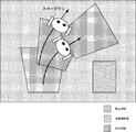
- FIG. 12 is a diagram illustrating an example of operation in each region of the robot 3 according to the third embodiment.
- the robot 1 captures the environment around the robot 1 in the form of a three-dimensional space and classifies it into various regions
- the robot 3 according to the third embodiment The surrounding environment is captured in the form of a two-dimensional space (two-dimensional plane) and classified into various regions.
- the control unit 11 classifies the road surface (two-dimensional space) around the robot 1 into one of a prohibited area, an unobserved area, and a free area.
- the control unit 11 determines, as a prohibited area, an area that is observed by the sensor 50 on the road surface around the robot 1 and that an obstacle is placed immediately above the road surface. Further, the control unit 11 determines an area not observed by the sensor 50 on the road surface around the robot 1 as an unobserved area. Further, the control unit 11 determines, as a free region, a region that is observed by the sensor 50 on the road surface around the robot 1 and that no obstacle is detected immediately above the road surface.
- the control unit 11 stores, in the storage unit 12, information indicating which of the above three classifications each of the areas obtained by dividing the space around the robot 3 is stored in the storage unit 12.
- a two-dimensional array may be prepared in the storage unit 12 as spatial information.
- each element of the two-dimensional array corresponds to each of the areas obtained by dividing the space (road surface) around the robot 3.
- the control unit 11 determines, for each element of the two-dimensional array, a region obtained by dividing the space around the robot 3 to be any region in the above three classifications
- the control unit 11 sets the element corresponding to the region.
- the value indicating the determined classification is stored. This value may be determined in advance as long as it is a value that can uniquely identify any of the prohibited region, the unobserved region, and the free region.
- the control unit 11 performs the robot 3 (robot main body at a high speed). 10) is moved.
- the control unit 11 moves the robot 3 at a lower speed than when the robot body 10 is operating in a free region.
- the control unit 11 Stops the movement of the robot body 10 completely.
- the robot body 10 comes into contact with the object that the robot 3 cannot recognize by changing the speed of the robot body 10 depending on whether or not the region in which the robot body 10 operates has been observed.
- the speed of the robot main body 10 is reduced in an unobserved area where there is a possibility of this. Thereby, even if the robot body 10 is in contact with an object, the influence on the object can be reduced. Further, since the speed is not reduced more than necessary in the free area, the robot 3 can move at high speed.
- FIG. 13 is a flowchart showing the operation of the robot 3 according to the third embodiment.
- Step S1 is the same as the process in the first embodiment described with reference to FIG. 8, and thus the same reference numerals are given and the description thereof is omitted.
- the robot 3 divides the space around the robot 3 from the observed data into a free area, an unobserved area, and a prohibited area (S20). Since the third embodiment is the same as the first embodiment except that the spatial information stored in the storage unit 12 is two-dimensional space information as described above, detailed description thereof is omitted.
- the robot 3 determines whether or not the robot 3 and the prohibited area overlap (S21). Specifically, the control unit 11 calculates an area including the robot body 10 in the space around the robot 3. For example, information indicating the shape of the robot body 10 is stored in the storage unit 12 in advance. The control unit 11 includes the robot body 10 when viewed in the vertical direction in the space around the robot 3 based on the shape of the robot body 10 indicated by the information stored in the storage unit 12 and the position of the robot 3. Calculate the area Then, when it is determined that the area calculated as the area including the robot body 10 is a prohibited area based on the spatial information, the control unit 11 determines that the robot 3 and the prohibited area overlap. .
- the robot 3 stops its operation for a certain time (S22). Specifically, the control unit 11 calculates command values for the actuators 21a and 21b so as to stop the movement of the robot 3. In other words, the control unit 11 calculates command values for the actuators 21a and 21b so that the angular velocities of the actuators 21a and 21b become zero. The control unit 11 outputs the calculated command value to each of the actuators 21a and 21b. Each of the actuators 21 a and 21 b stops the rotation of the wheels 22 a and 22 b according to the command value output from the control unit 11. That is, the movement of the robot 3 (robot body 10) stops.
- step S22 After the execution of step S22 is completed, the process returns to step S1. That is, the robot 3 stops the operation for a certain time and then executes the process from step S1. For example, when the obstacle in the prohibited area determined to overlap with the robot 3 is an operating object (for example, a person or an animal), the area disappears from the prohibited area after a certain period of time. 3 may be operable. Therefore, by operating in this way, the latest state of the space around the robot 3 is observed, and the operation can be resumed when the operation is possible.
- an operating object for example, a person or an animal
- the robot 3 determines whether or not the robot 3 and the unobserved area overlap (S22). Specifically, the control unit 11 calculates an area including the robot body 10 in the space around the robot 3. For example, the control unit 11 calculates an area including the robot body 10 in the space around the robot 3 when viewed in the vertical direction, similarly to step S21 described above. When the control unit 11 determines that the region calculated as the region including the robot body 10 is an unobserved region based on the spatial information, the control unit 11 determines that the robot 3 and the unobserved region overlap. To do.
- the robot 3 calculates the area A of the partial RUM where the robot 3 and the unobserved area overlap (S23). .
- the control unit 11 is based on the position of the robot 3, the shape of the robot body 10 indicated by the information stored in the storage unit 12, and the unobserved area indicated by the spatial information stored in the storage unit 12.
- the area A of the partial RUM where the robot body 10 and the unobserved region overlap in the vertical direction as shown in FIG. 14 is calculated.
- the robot 3 limits the moving speed of the robot 3 so as to be inversely proportional to the calculated area A (S24). Specifically, the control unit 11 calculates command values for the actuators 21a and 21b so that the moving speed of the robot 3 (robot body 10) decreases as the calculated area A increases. In other words, the control unit 11 calculates command values for the actuators 21a and 21b so that the angular velocities of the actuators 21a and 21b become smaller as the calculated area A becomes larger. The control unit 11 outputs the calculated command value to each of the actuators 21a and 21b. Each of the actuators 21a and 21b rotates the wheels 22a and 22b on the lower part of the robot body 10 at a speed according to the command value output from the control unit 11. As a result, the robot 1 moves at a speed inversely proportional to the area A. After the execution of step S24 is completed, the process returns to step S1.
- the process returns to step S1. That is, the robot 3 does not limit the moving speed of the robot 3. Specifically, the control unit 11 calculates command values for the actuators 21a and 21b so as not to limit the moving speed of the robot 3. In other words, the control unit 11 calculates command values for the actuators 21a and 21b so as not to limit the angular velocities of the actuators 21a and 21b. The control unit 11 outputs the calculated command value to each of the actuators 21a and 21b. Each of the actuators 21 a and 21 b rotates the wheels 22 a and 22 b at the lower part of the robot body 10 according to the command value output from the control unit 11. Thereby, the robot 3 moves at an unrestricted speed. That is, this speed is higher than the speed of the robot 3 when it is determined that the robot 3 and the unobserved region overlap.
- the third embodiment has been described above, but is not limited to the above-described content itself, and may be changed as appropriate without departing from the spirit of the present invention.
- the degree of decrease in the moving speed of the robot 3 increases as the area A of the portion RUM where the robot body 10 and the unobserved region overlap as shown in FIG.
- the present invention is not limited to this as long as the moving speed is limited when the robot body 10 and the unobserved area overlap.
- the movement speed of the robot 3 is set to the first speed, and when the robot body 10 and the unobserved area overlap, the robot 3 The moving speed may be a second speed lower than the first speed.
- the moving speed of the robot 3 may be a constant speed regardless of the area A of the part RUM where the robot body 10 and the unobserved region overlap. Further, the movement speed of the robot 3 may be set to the second speed when the area A of the part RUM where the robot body 10 and the unobserved region overlap exceeds a predetermined threshold. Further, as the distance between the robot 3 (robot main body 10) and the prohibited area becomes closer, the degree of decrease in the moving speed of the robot 3 may be increased.
- the robot 3 when the robot body 10 and the prohibited area overlap, the robot 3 is stopped (S22). However, the robot body 10 and the unobserved area overlap. As long as the moving speed of the robot 3 is further reduced than in the case, it is not limited to the complete stop (the moving speed is 0). That is, when it is determined that the robot body 10 and the prohibited area overlap, the control unit 11 moves the robot 3 at a lower speed than when the robot 3 and the unobserved area overlap. In addition, the actuators 21a and 21b may be controlled.
- the robot 3 when the robot body 10 and the prohibited area overlap, the robot 3 is stopped (S22), but other operations may be performed instead. In addition to that, other operations may be executed. For example, if it is determined that the prohibited area overlaps with the robot body 10, the control unit 11 determines that the prohibited area overlaps the robot body 10 instead of stopping the movement of the robot 3. The actuators 21a and 21b may be controlled so that the position of the robot 3 is returned to the state before the determination. In addition, as described above in the first embodiment, the user may be notified that the robot body 10 and the prohibited area are overlapped by the sound output device, the light emitting device, or the display device.
- the control unit 11 may leave the robot 3 stopped moving. Further, the control unit 11 may move the robot 3 again when receiving an instruction to resume the operation via the operation terminal 9 from the user. Specifically, when the operation terminal 9 receives an input for instructing operation resumption from an input device such as a touch panel from the user, the operation terminal 9 generates a radio signal instructing operation resumption and transmits the signal to the robot 3.
- the communication unit 13 of the robot 3 converts the radio signal received from the operation terminal 9 into an electric signal, and outputs it to the control unit 11 as information for instructing the operation resumption.
- the control unit 11 moves the robot 3 again in response to the output of information instructing operation resumption from the communication unit 13.
- the environment around the robot 3 is captured in the form of a two-dimensional space and classified into various areas.
- the environment is captured in the form of a three-dimensional space.
- the third embodiment reduces the driving force for moving the robot 3 as the driving force of the robot 3 when the robot 3 is moved in the unobserved area.
- the driving force of the arms 30 of the robots 1 and 2 is reduced as the driving force of the robot 3. It was like that.
- the location where the determination of overlap with an unobserved area or the like and the reduction of the driving force based on the determination result is a portion where there is a possibility of contact with an obstacle by the operation of the robot.
- Arbitrary locations may be determined in advance.
- the location where the overlap with the unobserved area or the like is determined and the location where the driving force is reduced based on the determination result may be the same location or different locations. May be,
- the external configuration of the robot 4 according to the fourth embodiment is the same as the external configuration of the robot 1 according to the first embodiment described with reference to FIG. However, as shown in FIG. 15, the robot 4 according to the fourth embodiment further includes angle sensors 23 a and 23 b as its internal configuration compared to the robot 1 according to the first embodiment. Moreover, in order to implement
- Each of the angle sensors 23a and 23b is a sensor that detects the angle of each of the actuators 21a and 21b.
- the angle sensor 23a is attached to the actuator 21a and detects the angle of the actuator 21a.
- the angle sensor 23 a outputs an angle signal indicating the detected angle to the control unit 11.
- the angle sensor 23b is attached to the actuator 21a and detects the angle of the actuator 21b.
- the angle sensor 33 b outputs an angle signal indicating the detected angle to the control unit 11.
- the control unit 11 feedback-controls the movement of the robot 4 (robot body 10).
- the control unit 11 performs feedback control (for example, position control or speed control) based on the angles detected by the angle sensors 23a and 23b as feedback control. I can't.
- the control unit 11 may perform arbitrary feedback control among feedback control such as position control, speed control, and torque control.
- the control unit 11 determines the respective angles of the actuators 21a and 21b and the target angles of the actuators 21a and 21b indicated by the angle signals output from the angle sensors 23a and 23b. Based on the deviation and the gain, a command value for each of the actuators 21a and 21b is generated and output to each of the actuators 21a and 21b.
- the control unit 11 differentiates the respective angles of the actuators 21a and 21b indicated by the angle signals output from the angle sensors 23a and 23b, so that the actuators 21a and 21b Each angular velocity is calculated. Based on the calculated angular velocities of the actuators 21a and 21b, the target angular velocities of the actuators 21a and 21b, and the gain, the control unit 11 generates command values for the actuators 21a and 21b, and the actuators 21a and 21b. Output to each of.
- the robot 4 is provided with an angular velocity sensor (tacho generator) that detects the angular velocity of the actuators 21a and 21b and outputs an angular velocity signal indicating the detected angular velocity to the control unit 11. Good. Then, the control unit 11 may use the angular velocities of the actuators 21a and 21b indicated by the angular signals output from the angular velocity sensors, instead of the angular velocities of the actuators 21a and 21b calculated from the angles.
- angular velocity sensor tilt generator
- a torque sensor that detects the torque of the actuators 21a and 21b and outputs a torque signal indicating the detected torque to the control unit 11 for each of the actuators 21a and 21b. Be prepared for. And the control part 11 is based on the deviation of each target torque of each actuator 21a, 21b and each actuator 21a, 21b which the torque signal output from a torque sensor shows, and the gain of actuators 21a, 21b. A command value for each is generated and output to each of the actuators 21a and 21b.
- the control unit 11 feedback-controls the movement of the robot 4 with a high gain.
- the control unit 11 may Feedback-controls the movement of the robot body 10 with a lower gain than when moving in the free region.
- the controller 11 may The movement of the robot body 10 is feedback controlled with a lower gain than when moving in the observation region.
- the robot 4 when the robot 4 is operated, by changing the gain in the feedback control of the movement of the robot body 10 depending on whether or not the region in which the robot body 10 operates has been observed, The collision force of the robot body 10 is reduced in an unobserved area where the robot body 10 may come into contact. Thereby, even if the robot body 10 is in contact with an object, the influence on the object can be reduced. In addition, since the gain is not lowered more than necessary in the free region, the robot 4 can be operated with high accuracy.
- FIG. 16 is a flowchart showing the operation of the robot 4 according to the fourth embodiment. Steps S1 and S20 to S22 are the same as those in the first embodiment described with reference to FIG. 8, and thus the same reference numerals are given and the description thereof is omitted.
- control unit 11 changes the gain of the feedback loop to a low gain (S30).
- control unit 11 changes the gain of the feedback loop to a lower gain (S31). This gain is a lower gain (second gain) than the gain (first gain) set in step S30.
- step S22 If it is determined that the robot 4 and the unobserved area do not overlap (S22: NO), the process returns to step S1. That is, the control unit 11 does not change the gain of the feedback loop to a low gain. Therefore, when step S30 or S31 is executed and the low gain is set as the gain of the feedback loop, the control unit 11 changes the gain of the feedback loop to a high gain. This gain is a gain (third gain) higher than the first gain set in step S30.
- the present invention is not limited to the above-described content itself, and may be changed as appropriate without departing from the spirit of the present invention.
- the gain reduction degree may be increased as the area A of the portion RUM where the robot body 10 and the unobserved area or the prohibited area overlap is increased.
- the area A is a portion where the robot body 10 and the unobserved area or the prohibited area overlap when the environment around the robot 4 is regarded as a three-dimensional space. You may replace with the volume of RUM.
- the driving force of the robot 4 is reduced by reducing the gain in the feedback control of the robot 4. That is, as long as the driving force of the robots 3 and 4 and thereby the force applied to the obstacles when the robots 3 and 4 come into contact with the obstacles are not limited only to the speed and the gain, Various parameters relating to the control may be controlled.
- Embodiments 1 and 2 and Embodiments 3 and 4 can be implemented in any combination.
- Robot main body 20 Moving carriage 30 Arm 40 Head 50 Sensor 60 Grip 11
- Control unit 12 Storage unit 13 Communication unit 21a, 21b Actuator 22a, 22b Wheel 23a, 23b Angle sensor 31a, 31b Actuator 32a, 32b Angle sensor 41 Actuator
Landscapes
- Engineering & Computer Science (AREA)
- Radar, Positioning & Navigation (AREA)
- Robotics (AREA)
- Mechanical Engineering (AREA)
- Aviation & Aerospace Engineering (AREA)
- Remote Sensing (AREA)
- Physics & Mathematics (AREA)
- General Physics & Mathematics (AREA)
- Automation & Control Theory (AREA)
- Manipulator (AREA)
Abstract
本発明は、未観測の領域内でロボットを動作させる場合であっても安全性を向上することができるロボット及びその制御方法を提供することを目的とする。本発明に係るロボットは、周辺の環境を観測しながら動作するロボットである。ロボットは、ロボットの周辺の環境情報を取得する環境情報取得手段と、環境情報取得手段により環境情報が取得できていない未観測領域内でロボットを動作させる場合には、ロボットの駆動力を減少させる制御手段と、を備える。
Description
本発明は、ロボット及びその制御方法に関する。
特許文献1には、対象物を認識しながらアーム等を対象物まで近づけることができるロボットが開示されている。このロボットは、カメラの位置情報と把持対象物の位置情報とに基づいて、アームの侵入を抑制する認識空間を算出する。ここで、認識空間とは、アームが侵入することにより、把持対象物の認識の妨げとなる空間を意味する。そして、このロボットは、認識空間への侵入を回避したアーム軌道を算出し、アームを制御する。
上述したようなロボットでは、カメラ等によって観測できる範囲は有限であるため、観測できない領域も残ってしまう。しかしながら、ロボットが認識(観測)していない領域に全くロボットを侵入させないようにしてしまうと、ロボットの動作が限定的となってしまうため、期待する動作を十分に行うことができなくなってしまう。一方で、ロボットが認識していない領域にロボットを侵入させる場合(例えば、その領域内でアームを動かす場合)には、その領域内の障害物等と接触してしまう可能性がある。
本発明は、上述した知見に基づいてなされたものであって、未観測の領域内でロボットを動作させる場合であっても安全性を向上することができるロボット及びその制御方法を提供することを目的とする。
本発明の第1の態様に係るロボットは、周辺の環境を観測しながら動作するロボットであって、ロボットの周辺の環境情報を取得する環境情報取得手段と、環境情報取得手段により環境情報が取得できていない未観測領域内でロボットを動作させる場合には、ロボットの駆動力を減少させる制御手段と、を備えることを特徴とするものである。
本発明の第2の態様に係る制御方法は、周辺の環境を観測しながら動作するロボットの制御方法であって、前記ロボットの周辺の環境情報を取得するステップと、前記ロボットが前記環境情報が取得できていない未観測領域内で動作しているか否かを判定するステップと、前記未観測領域内で動作していると判定した場合には、前記ロボットの駆動力を減少させるステップと、を備えることを特徴とするものである。
上述した本発明の各態様によれば、未観測の領域内で動作させる場合であっても安全性を向上することができるロボット及びその制御方法を提供することができる。
以下に図面を参照しながら、本発明の好適な実施の形態について説明する。以下の実施の形態に示す具体的な数値等は、発明の理解を容易とするための例示にすぎず、特に断る場合を除き、それに限定されるものではない。また、以下の記載及び図面では、説明の明確化のため、当業者にとって自明な事項等については、適宜、省略及び簡略化がなされている。
<発明の実施の形態1>
まず、本実施の形態1に係るロボット1について説明する。図1を参照して、本実施の形態1に係るロボット1の外部構成について説明する。図1は、本実施の形態1に係るロボット1の外部構成図である。
まず、本実施の形態1に係るロボット1について説明する。図1を参照して、本実施の形態1に係るロボット1の外部構成について説明する。図1は、本実施の形態1に係るロボット1の外部構成図である。
ロボット1は、ロボット本体10、移動台車20、アーム30、及び頭部40を有している。ロボット1は、典型的には、家庭内において人が行う作業を、人に代わり実行するための生活支援ロボットである。ロボット1は、例えば、任意の場所に移動し、物を拾い人に届ける、窓を開ける等の作業を実行する。
移動台車20は、その上方でロボット本体10を支持するように、その上部がロボット本体10の下部に連結されている。移動台車20は、その下部に設けられた車輪(図示せず)を駆動することでロボット1を移動させる。
アーム30は、ロボット本体10の前方に突出するように、ロボット本体10の前部に接続されている。アーム30は、多関節のアームである。アーム30は、その先端部に、任意の物体を把持できるグリップ(把持部)6を含む。これにより、ロボット1は、アーム30の各関節の角度を調整することで、グリップ60を所望の位置に移動させ、その位置に存在する物体を把持することができる。
頭部40は、ロボット本体10の上方でロボット本体10に支持されるように、ロボット本体10の上部に連結されている。頭部40は、その前方をセンサ50によって観測可能となるように、その前部にセンサ50が取り付けられている。センサ50は、ロボット1の周辺の環境を観測し、観測した環境を示す環境情報を取得するセンサである。センサ50は、典型的には、ロボット1からロボット1の周辺の物体までの距離を観測可能な3次元距離センサとなる。ここで、3次元距離センサは、光学式、超音波式、及びレーザ光線式等の各種方式のうち、任意の方式のものを使用するようにしてよい。なお、センサ50として環境情報を取得する手段は、3次元距離センサに限定されない。例えば、センサ50としてカメラを備えるようにし、カメラで撮像した画像を示す画像情報を環境情報として取得するようにしてもよい。
センサ50は、測定可能な角度範囲が所定の角度に限られている。一方で、頭部40とロボット本体10との連結部は、頭部40を動作可能となるように多自由度の関節構造となっている。例えば、関節構造として少なくとも2自由度以上を有するようにすることで、頭部40は、少なくとも上下左右に動作させることが可能とされている。これにより、センサ50の測定可能な角度範囲が限られていても、頭部40を動作させることで広範囲を観測することを可能としている。
操作端末9は、ロボット1と無線又は有線によって通信可能な情報処理端末である。本実施の形態では、操作端末9とロボット1とが無線によって通信する例について説明する。操作端末9は、デスクトップPCのような据え置き型の情報処理端末であってもよいが、好ましくは、ユーザが生活空間において制限なくロボット1を操作可能とするために、携帯型の情報処理端末であるとよい。携帯型の情報処理端末は、スマートフォン、又はタブレット端末等である。
ユーザは、操作端末9によってロボット1に対して、上述したような人が行う作業を指示することができる。ロボット1は、ユーザから指示された作業をユーザに代わり実行する。このようにして、ロボット1によってユーザの生活が支援される。
上述した構成により、ロボット1は、ユーザから指示された作業を実行するにあたり、センサ50によってロボット1の周辺の環境を観測し、観測した環境における障害物を避けて行動する。
続いて、図2を参照して、本実施の形態1に係るロボット1の内部構成について説明する。図2は、本実施の形態1に係るロボット1の内部構成図である。
ロボット1は、制御部11、記憶部12、通信部13、アクチュエータ21a、21b、車輪22a、22b、アクチュエータ31a、31b、角度センサ(ポテンショメータ)32a、32b、及びアクチュエータ41を有する。制御部11、記憶部12、及び通信部13は、ロボット本体10に含まれる。アクチュエータ21a、21b及び車輪22a、22bは、移動台車20に含まれる。アクチュエータ31a、31b及び角度センサ32a、32bは、アーム30に含まれる。アクチュエータ41は、頭部40に含まれる。
制御部11は、ロボット1を統括的に制御する。制御部11は、CPU(Central Processing Unit)を有しており、そのCPUが記憶部12に格納されたプログラムを実行することで、制御部11としての各種処理を実現する。すなわち、このプログラムは、制御部11が有するCPUに制御部11としての各種処理を実行させるためのコードを含んでいる。
記憶部12は、上記プログラムや、その他の制御部11が使用する各種情報が格納される。記憶部12は、上記プログラムや各種情報を格納可能な記憶装置の少なくとも1つを含む。記憶装置として、例えば、メモリ及びハードディスク等の少なくとも1つを任意に使用してよい。
通信部13は、操作端末9に送信するために制御部11から出力された情報を、無線信号に変換し、操作端末9に送信する。通信部13は、操作端末9から受信した無線信号を、制御部11で処理可能な情報となるように電気信号に変換し、制御部11に出力する。
アクチュエータ21a、21bは、ロボット1の車輪22a、22bを駆動する。アクチュエータ21aは、制御部11からの制御によって駆動され、車輪22aを回転させる。アクチュエータ21bは、制御部11からの制御によって駆動され、車輪22bを回転させる。
車輪22a及び車輪22bは、上述した移動台車20の下部に取り付けられた車輪に該当する。すなわち、制御部11は、アクチュエータ21a、21bを制御して、車輪22a、22bを回転させることでロボット1を移動させる。
アクチュエータ31a、31bは、ロボット1のアーム30を駆動する。アクチュエータ31a、31bのそれぞれは、アーム30の関節として設けられている。なお、ここでは、アーム30が、アクチュエータ31aとアクチュエータ31bとの2つの関節を有する例について説明するが、アーム30の関節数は、これに限られない。
角度センサ32a、32bのそれぞれは、アーム30の各関節の角度を検出するセンサである。角度センサ32aは、アクチュエータ31aに取り付けられており、アクチュエータ31aの角度を検出する。角度センサ32aは、検出した角度を示す角度信号を制御部11に出力する。角度センサ32bは、アクチュエータ31bに取り付けられており、アクチュエータ31bの角度を検出する。角度センサ32bは、検出した角度を示す角度信号を制御部11に出力する。これにより、制御部11は、角度センサ32a、32bのそれぞれから出力された角度信号が示す角度に基づいて、アーム30の状態を認識することが可能となる。
アクチュエータ41は、ロボット1の頭部40を駆動する。アクチュエータ41は、例えば、多自由度(2自由度以上の所定自由度)のアクチュエータとして、頭部40を上下左右に動作可能としてよい。また、頭部40を駆動するアクチュエータ41を複数有するようにして、頭部40の多自由度での駆動を実現するようにしてもよい。また、アクチュエータ41として1自由度のアクチュエータを1つだけ有するようにして、頭部40が上下又は左右のみに動作するようにされていてもよい。
続いて、図3~図5を参照して、本実施の形態1に係るロボット1の環境観測方法について説明する。まず、図3を参照して、本実施の形態1に係るロボット1の環境観測方法について説明する。図3は、本実施の形態1に係るロボット1が観測する環境の一例を示す図である。
図3に示すように、ロボット1が机の上に四角柱の物体が置かれている環境を観測する例について説明する。この環境において、図3に示すように、机の一辺の正面斜め上方からロボット1がセンサ50によって環境を観測したものとする。
ロボット1は、観測した環境となるロボット1の周辺の空間を、次の3つの領域のうちのいずれかの領域に分類する。
禁止領域 :障害物があることを観測できている領域
未観測領域 :障害物があるか否かが観測できていない不確定領域
自由領域 :障害物がないことを観測できている領域
禁止領域 :障害物があることを観測できている領域
未観測領域 :障害物があるか否かが観測できていない不確定領域
自由領域 :障害物がないことを観測できている領域
具体的には、制御部11は、図4に示すように、ロボット1の周辺の空間において、センサ50によって観測されており、かつ、障害物を検出した領域を禁止領域として判定する。例えば、制御部11は、センサ50に対して奥行き方向に、障害物を検出した位置から所定の距離の範囲となる領域を禁止領域として判定する。これにより、例えば、四角柱の物体の正面(センサ50側の側面)と上面から一定範囲と、机の天板及び正面側の足が禁止領域として決定される。
また、制御部11は、図4に示すように、ロボット1の周辺の空間において、センサ50によって観測していない領域を未観測領域として判定する。したがって、このセンサ50によって観測していない領域には、例えば、禁止領域よりもさらにセンサ50に対して奥行き方向となる領域が含まれる。これにより、例えば、センサ50に対して四角柱、机の天板及び正面側の足の後方にあたる領域(正面と反対側の足を含む)が未観測領域として判定される。なお、過去の観測で、禁止領域か自由領域かが判定されている領域については、その判定結果を維持する。
また、制御部11は、図4に示すように、ロボット1の周辺の空間において、センサ50によって観測されており、かつ、障害物が検出されなかった領域を自由領域として判定する。例えば、制御部11は、障害物が検出される位置までの空間を自由領域として判定する。これにより、例えば、ロボット1(センサ50)から四角柱、机、及びその他の物体(壁、床等)までの空間が自由領域として判定される。
ここで、制御部11は、ロボット1の周辺の空間を分割した領域のそれぞれが、上記3つの分類のいずれの領域に属するかを示す情報を空間情報として記憶部12に記憶することで、ロボット1の周辺の空間の観測結果を管理する。例えば、単純には、空間情報として三次元配列を記憶部12に用意してもよい。この場合、この三次元配列の各要素は、ロボット1の周辺の空間を格子状に分割した領域のそれぞれに対応する。そして、制御部11は、図5に示すように、ロボット1の周辺の空間を分割した複数の領域において、ある領域が上記3つの分類におけるいずれの領域となるかを判定した場合、その領域に対応する三次元配列の要素に、判定結果となる分類を示す値を格納する。この値は、禁止領域、未観測領域、及び自由領域のうちのいずれの領域であるかを一意に特定することができる値であれば、任意の値を予め定めるようにしてよい。
これにより、制御部11は、ロボット1を、ロボット1の周辺の空間を分割した複数の領域のうち、ある領域に侵入しようとする場合、空間情報のその領域に対応する値を参照することで、その領域が、禁止領域、未観測領域、及び自由領域のうちのいずれの領域であるかを認識することができる。
続いて、図6A~図6C、及び図7A~図7Cを参照して、本実施の形態1に係るロボット1の動作方法について説明する。図6Aは、本実施の形態1に係るロボット1の自由領域における動作を示す図である。図6Bは、本実施の形態1に係るロボット1の未観測領域における動作を示す図である。図6Cは、本実施の形態1に係るロボット1の禁止領域における動作を示す図である。
図6Aに示すように、アーム30の全てが自由領域で動作していると判定した場合、制御部11は、高い速度でアーム30を動作させる。図6Bに示すように、アーム30の少なくとも一部が未観測領域で動作していると判定した場合(アーム30が未観測領域に接触する場合を含めてもよい)、制御部11は、アーム30が自由領域で動作している場合よりも低い速度でアーム30を動作させる。図6Cに示すように、アーム30の少なくとも一部が禁止領域で動作していると判定した場合(アーム30が禁止領域に接触する場合を含めてもよい)、制御部11は、アーム30を完全に停止させる。
このように、ロボット1を動作させる際に、アーム30が動作する領域が観測済みか否かによりアーム30の速度を変えることにより、ロボット1が認識できていない物体とアーム30が接触する可能性がある未観測領域ではアーム30の速度を落としている。これにより、万が一、アーム30が物体と接触した場合であっても、その物体に対する影響を軽減することができる。また、自由領域においては必要以上に速度を落とすことが無いため、ロボット1の高速な動作が可能となる。
ここで、ロボット1は、アーム30が未観測領域とオーバーラップしている体積によって動作を変える。図7Aは、本実施の形態1に係るロボット1の自由領域における動作を示す図である。図7Bは、本実施の形態1に係るロボット1の未観測領域における動作を示す図である。図7Cは、本実施の形態1に係るロボット1の禁止領域における動作を示す図である。
図7Aに示すように、アーム30の全てが自由領域に含まれる場合には、速い速度でアーム30を動かす。図7Bに示すように、アーム30の少なくとも一部が未観測領域に含まれる場合(アーム30が未観測領域に接触する場合を含めてもよい)は、その進入の度合いに応じて速度を落とす。図7Cに示すように、アームの少なくとも一部が禁止領域に含まれる場合(アーム30が禁止領域に接触する場合を含めてもよい)には、アーム30を停止させる。
続いて、図8を参照して、本実施の形態1に係るロボット1の動作について説明する。図8は、本実施の形態1に係るロボット1の動作を示すフローチャートである。
ロボット1は、ロボット1に搭載されたセンサ50で、ロボット1の周辺の環境を観測する(S1)。具体的には、センサ50は、ロボット1の周辺の環境を観測し、観測した環境を示す環境情報を生成して制御部11に出力する。例えば、センサ50が3次元距離センサである場合、センサ50は、各方位毎の障害物までの距離を示す情報を環境情報として制御部11に出力する。
ロボット1は、観測されたデータからロボット1の周辺の空間を、自由領域、未観測領域、及び禁止領域に分ける(S2)。具体的には、制御部11は、センサ50から出力された環境情報が示す環境に基づいて、障害物が存在する領域(禁止領域)と障害物が存在しない領域(自由領域)とを判定する。制御部11は、その判定結果に従って記憶部12に格納された空間情報を更新する。例えば、空間情報で示される各領域は、初期値として未観測領域を示すようにする。そして、制御部11は、空間情報において、禁止領域として判定した領域は禁止領域を示すように変更し、自由領域として判定した領域は自由領域を示すように変更する。
ロボット1は、ロボット1と禁止領域とがオーバーラップしているか否かを判定する(S3)。具体的には、制御部11は、ロボット1の周辺の空間において、アーム30が含まれる領域を計算する。例えば、リンク(アーム30の関節間の部分)及びグリップ60等のアーム30の各構成要素の形状を示す情報を記憶部12に予め格納しておく。制御部11は、ロボット1の位置と、記憶部12に格納されたその情報が示すアーム30の各構成要素の形状と、アーム30の角度センサ32a、32bのそれぞれから出力された角度信号が示す関節角度に基づいて、ロボット1の周辺の空間においてアーム30が含まれる領域を計算する。そして、制御部11は、アーム30が含まれる領域として計算した領域が、空間情報に基づいて禁止領域であると判定される場合、ロボット1と禁止領域とがオーバーラップしていると判定する。
ここで、ロボット1の位置(現在位置)は、任意の手法により特定するようにすればよい。例えば、制御部11は、環境情報に基づいて、ロボット1の周りの障害物からの相対位置からロボット1の現在位置を特定するようにしてもよい。また、アクチュエータ21a、21bのそれぞれに対して角度センサを備えるようにし、角度センサで検出されたアクチュエータ21a、21bの角度に基づいて所定のロボット1の基準位置からの総回転角度(車輪が回転した回数)を計算し、計算した総回転角度と車輪の大きさとに基づいて、ロボット1の現在位置を特定するようにしてもよい。
ロボット1と禁止領域とがオーバーラップしていると判定した場合(S3:YES)、ロボット1は、その動作を一定時間停止させる(S4)。具体的には、制御部11は、アーム30の動作を停止させるように、アクチュエータ31a、31bのそれぞれに対する指令値を計算する。言い換えると、制御部11は、アクチュエータ31a、31bのそれぞれの角速度が0となるように、アクチュエータ31a、31bのそれぞれに対する指令値を計算する。制御部11は、計算した指令値をアクチュエータ31a、31bのそれぞれに出力する。アクチュエータ31a、31bのそれぞれは、制御部11から出力された指令値に従って、アーム30の関節の回転を停止する。すなわち、アーム30の動作が停止される。
ステップS4の実行終了後は、ステップS1に戻る。すなわち、ロボット1は、その動作を一定時間停止させた後に、ステップS1から処理を実行する。例えば、ロボット1とオーバーラップしていると判定された禁止領域における障害物が動作する物体(例えば人又は動物等)である場合、一定時間経過後には、その領域は禁止領域で無くなって、ロボット1が動作可能となっている可能性がある。よって、このような処理により、ロボット1の周辺の空間の最新の状態を観測し、動作可能となっている場合には、ロボット1の動作を再開することを可能とする。
ロボット1と禁止領域とがオーバーラップしていないと判定した場合(S3:NO)、ロボット1は、ロボット1と未観測領域とがオーバーラップしているか否かを判定する(S5)。具体的には、制御部11は、ロボット1の周辺の空間において、アーム30が含まれる領域を計算する。例えば、制御部11は、上述のステップS3と同様に、ロボット1の周辺の空間においてアーム30が含まれる領域を計算する。そして、制御部11は、アーム30が含まれる領域として計算した領域が、空間情報に基づいて未観測領域であると判定される場合、ロボット1と未観測領域とがオーバーラップしていると判定する。なお、アーム30が含まれる領域は、ステップS3で計算したものをそのまま利用するようにしてもよい。
ロボット1と未観測領域とがオーバーラップしていると判定した場合(S5:YES)、ロボット1は、ロボット1と未観測領域がオーバーラップしている部分RUMの体積Sを計算する(S6)。具体的には、制御部11は、ロボット1の位置と、記憶部12に格納された情報が示すアーム30の各構成要素の形状と、アーム30の角度センサ32a、32bのそれぞれから出力された角度信号が示す関節角度と、記憶部12に格納された空間情報が示す未観測領域に基づいて、図9に示すようなアーム30と未観測領域がオーバーラップしている部分RUMの体積Sを計算する。
ロボット1は、計算した体積Sに反比例するようにアーム30の速度を制限する(S7)。具体的には、制御部11は、計算した体積Sが大きくなるに従ってアーム30の速度が小さくなるように、アクチュエータ31a、31bのそれぞれに対する指令値を計算する。言い換えると、制御部11は、計算した体積Sが大きくなるに従ってアクチュエータ31a、31bの角速度が小さくなるように、アクチュエータ31a、31bのそれぞれに対する指令値を計算する。制御部11は、計算した指令値をアクチュエータ31a、31bのそれぞれに出力する。アクチュエータ31a、31bのそれぞれは、制御部11から出力された指令値に従った速度で、アーム30の関節を回転させる。これにより、アーム30が体積Sに反比例した速度で動作する。ステップS6の実行終了後は、ステップS1に戻る。
ロボット1と未観測領域とがオーバーラップしていないと判定した場合(S5:NO)、ステップS1に戻る。すなわち、ロボット1は、アーム30の速度を制限しない。具体的には、制御部11は、アーム30の速度を制限しないように、アクチュエータ31a、31bのそれぞれに対する指令値を計算する。言い換えると、制御部11は、アクチュエータ31a、31bの角速度を制限しないように、アクチュエータ31a、31bのそれぞれに対する指令値を計算する。制御部11は、計算した指令値をアクチュエータ31a、31bのそれぞれに出力する。アクチュエータ31a、31bのそれぞれは、制御部11から出力された指令値に従った速度で、アーム30の関節を回転させる。これにより、アーム30が制限されない速度で動作する。すなわち、この速度は、ロボット1と未観測領域とがオーバーラップしていると判定した場合におけるアーム30の速度よりも高い速度となる。
以上、本実施の形態1について説明したが、上述した内容そのものに限られず、趣旨を逸脱しない範囲で適宜変更してよい。例えば、上記説明では、図9に示すようなアーム30と未観測領域がオーバーラップしている部分RUMの体積Sが大きくなるに従って、アーム30の速度の減少度合いを大きくするようにしている(S6、S7)が、アーム30と未観測領域とがオーバーラップしている場合に、速度が制限されるのであれば、これに限られない。例えば、アーム30と未観測領域がオーバーラップしていない場合には、アーム30の速度を第1の速度とし、アーム30と未観測領域がオーバーラップしている場合には、アーム30の速度を第1の速度よりも低い第2の速度とするようにしてもよい。すなわち、アーム30の速度は、アーム30と未観測領域がオーバーラップしている部分RUMの体積Sに関わらず、一定の速度とするようにしてもよい。また、アーム30と未観測領域がオーバーラップしている部分RUMの体積Sが所定の閾値を超えた場合に、アーム30の速度を第2の速度とするようにしてもよい。また、アーム30と禁止領域との距離が近くなるに従って、アーム30の速度の減少度合いを大きくするようにしてもよい。
また、上記説明では、アーム30と禁止領域がオーバーラップしている場合には、アーム30の動作を停止させる(S4)ようにしているが、アーム30と未観測領域がオーバーラップしている場合よりもさらにアーム30の速度を減少させるものであれば、完全に停止させる(速度0とする)ことには限られない。すなわち、アーム30と禁止領域がオーバーラップしていると判定した場合には、制御部11は、アーム30と未観測領域がオーバーラップしている場合よりも低い速度でアーム30を動作させるように、アクチュエータ31a、31bを制御するようにしてもよい。
また、上記説明では、アーム30と禁止領域がオーバーラップしている場合には、アーム30の動作を停止させる(S4)ようにしているが、それに代えて他の動作を実施するようにしてもよく、それに加えて他の動作を実行するようにしてもよい。例えば、アーム30と禁止領域がオーバーラップしていると判定した場合には、制御部11は、アーム30の動作を停止させることに代えて、アーム30が禁止領域がオーバーラップしていると判定する前の状態にアーム30を戻すように、アクチュエータ31a、31bを制御するようにしてもよい。また、他の動作として、ロボット1にスピーカーのような出音装置を備えるようにし、出音装置からアラーム音声を出音することでアーム30と禁止領域がオーバーラップしていることをユーザに通知するようにしてもよい。また、他の動作として、ロボット1にLEDのような発光装置を備えるようにし、発光装置を発光させることでロボット1と禁止領域がオーバーラップしていることをユーザに通知するようにしてもよい。また、他の動作として、ロボット1に液晶ディスプレイ又は有機ELディスプレイ等の表示装置を備えるようにし、表示装置にアラーム画像を表示することでアーム30と禁止領域がオーバーラップしていることをユーザに通知するようにしてもよい。
また、上記説明では、アーム30の動作を一定時間停止させた後に、再度環境を観測し、アーム30と禁止領域がオーバーラップしなくなっている場合には、アーム30を再度動作させるようにしている(S4、S1、S3:NO)が、これに限られない。例えば、制御部11は、アーム30の動作を停止させたままとするようにしてもよい。また、制御部11は、ユーザから操作端末9を介して動作再開の指示を受けた場合に、アーム30を再度動作させるようにしてもよい。具体的には、操作端末9は、ユーザからタッチパネル等の入力装置によって動作再開を指示する入力を受けた場合、動作再開を指示する無線信号を生成し、ロボット1に送信する。ロボット1の通信部13は、操作端末9から受信した無線信号を電気信号に変換し、動作再開を指示する情報として制御部11に出力する。制御部11は、通信部13からの動作再開を指示する情報の出力に応じて、アーム30を再度動作させる。
以上に説明したように、本実施の形態1に係るロボット1は、ロボット1の周辺の環境情報を取得するセンサ50(環境情報取得手段)と、環境情報取得手段により環境情報が取得できていない未観測領域内でロボット1を動作させる場合には、ロボット1の駆動力を減少させる制御部11(制御手段)と、を備えるようにしている。
そのため、ロボット1が障害物に接触したとしても、障害物に対して大きな衝撃を与えることもなく、ロボット1が障害物から大きな衝撃を受けることもない。したがって、ロボット1を未観測領域内で動作させる場合であっても安全性を向上することができる。
また、本実施の形態1に係るロボット1は、ロボット1の周辺の領域のそれぞれが、未観測領域、禁止領域、及び自由領域のうち、いずれの領域であるのかを示す空間情報(領域情報)が格納される記憶部12(格納手段)を備えるようにしている。そして、制御部11は、センサ50により取得された環境情報に基づいて、ロボット1の周辺の領域が、未観測領域、禁止領域、及び自由領域のうち、いずれの領域であるのかを判定して、その判定結果に応じて空間情報を更新するとともに、空間情報に基づいて、ロボット1を動作させる領域が、未観測領域、禁止領域、及び自由領域のうち、いずれの領域であるのかを判定するようにしている。
そのため、ロボット1が、現時点でセンサ50の観測可能範囲にない障害物であっても、過去にセンサ50によって観測している障害物を回避して動作することが可能となる。したがって、ロボット1が動作する際の安全性をより向上することができる。
また、本実施の形態1に係るロボット1では、制御部11が未観測領域に含まれるロボット1の体積が大きくなるに従ってロボット1の駆動力の減少度合いが大きくなるように、ロボット1の駆動力を減少させるようにしている。
そのため、ロボット1が未観測領域の中により大きく侵入し、障害物と接触する蓋然性が高まるほど、ロボット1の駆動力をより大きく減少させることができる。したがって、ロボット1が動作する際の安全性をより向上することができる。
<発明の実施の形態2>
続いて、本実施の形態2に係るロボット2について説明する。ここで、上記の実施の形態1では、アーム30と未観測領域とのオーバーラップ部分に応じてアーム30の速度自体を変更していたが、アーム30の速度自体を変更するのではなく、アーム30のフィードバックループのゲインを変更することで、ロボット2のアーム30が未観測領域における障害物にぶつかった際の衝撃力を緩和することができる。本実施の形態2では、その手法について説明する。
続いて、本実施の形態2に係るロボット2について説明する。ここで、上記の実施の形態1では、アーム30と未観測領域とのオーバーラップ部分に応じてアーム30の速度自体を変更していたが、アーム30の速度自体を変更するのではなく、アーム30のフィードバックループのゲインを変更することで、ロボット2のアーム30が未観測領域における障害物にぶつかった際の衝撃力を緩和することができる。本実施の形態2では、その手法について説明する。
本実施の形態2に係るロボット2の構成については、図1及び図2を参照して説明した実施の形態1に係るロボット1の構成と同様であるため、その説明を省略する。ただし、上述の手法による制御を実現するために、制御部11の動作が一部異なる。
本実施の形態2では、制御部11は、ロボット2のアーム30をフィードバック制御する。上述した構成によれば、制御部11は、フィードバック制御として、角度センサ32a、32bによって検出される角度に基づいてフィードバック制御(例えば位置制御又は速度制御)を実施する。しかしながら、フィードバック制御の種類は、これに限られない。制御部11は、例えば位置制御、速度制御、及びトルク制御等の各種フィードバック制御のうち、任意のフィードバック制御を実施するようにしてよい。
例えば、位置制御を実施する場合には、制御部11は、角度センサ32a、32bのそれぞれから出力される角度信号が示すアクチュエータ31a、31bのそれぞれの角度とアクチュエータ31a、31bのそれぞれの目標角度の偏差と、ゲインとに基づいて、アクチュエータ31a、31bのそれぞれに対する指令値を生成し、アクチュエータ31a、31bのそれぞれに出力する。
また、速度制御を実施する場合には、制御部11は、角度センサ32a、32bから出力される角度信号が示すアクチュエータ31a、31bのそれぞれの角度を微分することで、アクチュエータ31a、31bのそれぞれの角速度を算出する。制御部11は、算出したアクチュエータ31a、31bのそれぞれの角速度とアクチュエータ31a、31bのそれぞれの目標角速度の偏差と、ゲインとに基づいて、アクチュエータ31a、31bのそれぞれに対する指令値を生成し、アクチュエータ31a、31bのそれぞれに出力する。なお、アクチュエータ31a、31bのそれぞれに対して、アクチュエータ31a、31bの角速度を検出し、検出した角速度を示す角速度信号を制御部11に出力する角速度センサ(タコジェネレータ)をロボット2に備えるようにしてもよい。そして、制御部11は、角度から算出するアクチュエータ31a、31bの角速度に代えて、角速度センサから出力される角度信号が示すアクチュエータ31a、31bの角速度を使用するようにしてもよい。
なお、トルク制御を実施する場合には、アクチュエータ31a、31bのそれぞれに対して、アクチュエータ31a、31bのトルクを検出し、検出したトルクを示すトルク信号を制御部11に出力するトルクセンサをロボット2に備えるようにする。そして、制御部11は、トルクセンサから出力されるトルク信号が示すアクチュエータ31a、31bのそれぞれのトルクとアクチュエータ31a、31bのそれぞれの目標トルクの偏差と、ゲインとに基づいて、アクチュエータ31a、31bのそれぞれに対する指令値を生成し、アクチュエータ31a、31bのそれぞれに出力する。
なお、フィードバック制御のおける具体的な指令値の導出方法は、既知の技術を利用すればよいため、詳細な説明は省略する。
続いて、図10A~図10Cを参照して、本実施の形態2に係るロボット2の動作方法について説明する。図10Aは、本実施の形態2に係るロボット2の自由領域における動作を示す図である。図10Bは、本実施の形態2に係るロボット2の未観測領域における動作を示す図である。図10Cは、本実施の形態2に係るロボット2の禁止領域における動作を示す図である。
図10Aに示すように、アーム30の全てが自由領域で動作していると判定した場合、制御部11は、高いゲインでアーム30をフィードバック制御する。図10Bに示すように、アーム30の少なくとも一部が未観測領域で動作していると判定した場合(アーム30が未観測領域に接触する場合を含めてもよい)、制御部11は、アーム30が自由領域で動作している場合よりも低いゲインでアーム30をフィードバック制御する。図10Cに示すように、アーム30の少なくとも一部が禁止領域で動作していると判定した場合(アーム30が禁止領域に接触する場合を含めてもよい)、制御部11は、アーム30が未観測領域で動作している場合よりも、さらに低いゲインでアーム30をフィードバック制御する。
このように、ロボット2を動作させる際に、アーム30が動作する領域が観測済みか否かによりアーム30のフィードバック制御におけるゲインを変えることにより、認識できていない物体と接触する可能性がある未観測領域ではアーム30のゲインを落としている。これにより、万が一、物体と接触した場合であっても、その物体に対する影響を軽減することができる。また、自由領域においては必要以上にゲインを落とすことが無いため、ロボット2の高精度な動作が可能となる。
続いて、図11を参照して、本実施の形態2に係るロボット2の動作について説明する。図11は、本実施の形態2に係るロボット2の動作を示すフローチャートである。ステップS1~S3、S5については、図8を参照して説明した実施の形態1における処理と同様であるため、同一の符号を付し、その説明を省略する。
ロボット2と未観測領域とがオーバーラップしていると判定した場合(S5:YES)、制御部11は、フィードバックループのゲインを低いゲインに変更する(S10)。
ロボット2と禁止領域とがオーバーラップしていると判定した場合(S3:YES)、制御部11は、フィードバックループのゲインを、さらに低いゲインに変更する(S11)。このゲインは、ステップS10で設定するゲイン(第1のゲイン)よりも、さらに低いゲイン(第2のゲイン)となる。
ロボット2と未観測領域とがオーバーラップしていないと判定した場合(S5:NO)、ステップS1に戻る。すなわち、制御部11は、フィードバックループのゲインを、低ゲインに変更しない。よって、ステップS10又はS11が実行されて、フィードバックループのゲインとして低ゲインが設定されている場合には、制御部11は、フィードバックループのゲインを高いゲインに変更する。このゲインは、ステップS10で設定するゲイン(第1のゲイン)よりも、高いゲイン(第3のゲイン)となる。
以上、本実施の形態2について説明したが、上述した内容そのものに限られず、趣旨を逸脱しない範囲で適宜変更してよい。例えば、ロボット2と未観測領域とがオーバーラップしていると判定した場合、及び、ロボット2と禁止領域とがオーバーラップしていると判定した場合において、低いゲインを設定するときに、さらに、ロボット2と未観測領域又は禁止領域がオーバーラップしている部分RUMの体積Sが大きくなるに従って、ゲインの減少度合いを大きくするようにしてもよい。
また、上記説明では、ロボット2と禁止領域がオーバーラップしている場合には、アーム30のフィードバック制御におけるゲインを低いゲインに変更するようにしているが、それに代えてアーム30の動作を停止させるようにしてもよい。また、実施の形態1において上述したように、それに代えて他の動作を実施するようにしてもよく、それに加えて他の動作を実行するようにしてもよい。
以上に説明したように、本実施の形態2では、ロボット2のフィードバック制御におけるゲインを減少させることで、ロボット2の駆動力を減少させるようにしている。すなわち、ロボット1、2の駆動力及びそれにより障害物にロボット1、2が接触した際に障害物に加わる力を減少させるものであれば、速度及びゲインのみに限られず、ロボット1、2の制御に関する様々なパラメータを制御するようにしてもよい。
<発明の実施の形態3>
続いて、本実施の形態3に係るロボット3について説明する。ここで、上記の実施の形態1では、ロボット1のアーム30の速度を制御する場合について説明したが、同様に、ロボット1(ロボット本体10)の移動速度を制御するようにしてもよい。これによれば、ロボット1(ロボット本体10)が未観測領域における障害物にぶつかった際の衝撃力を緩和することができる。本実施の形態3では、その手法について説明する。
続いて、本実施の形態3に係るロボット3について説明する。ここで、上記の実施の形態1では、ロボット1のアーム30の速度を制御する場合について説明したが、同様に、ロボット1(ロボット本体10)の移動速度を制御するようにしてもよい。これによれば、ロボット1(ロボット本体10)が未観測領域における障害物にぶつかった際の衝撃力を緩和することができる。本実施の形態3では、その手法について説明する。
本実施の形態3に係るロボット3の構成については、図1及び図2を参照して説明した実施の形態1に係るロボット1の構成と同様であるため、その説明を省略する。ただし、上述の手法による制御を実現するために、制御部11の動作が一部異なる。なお、本実施の形態3に係るロボット1は、アーム30を有さない台車型のロボットであってもよい。
本実施の形態3では、制御部11は、ロボット本体10が自由領域、未観測領域、及び禁止領域のうち、いずれの領域で動作しているかによって、ロボット1(ロボット本体10)の移動速度を変更する。
続いて、図12を参照して、本実施の形態3に係るロボット3の環境認識方法及び動作方法について説明する。図12は、本実施の形態3に係るロボット3の各領域で動作する例を示す図である。
実施の形態1に係るロボット1は、ロボット1の周辺の環境を3次元空間の形式で捉えて各種領域に分類するようにしていたが、本実施の形態3に係るロボット3は、ロボット1の周辺の環境を2次元空間(2次元平面)の形式で捉えて各種領域に分類する。具体的には、制御部11は、ロボット1の周辺の路面(2次元空間)を、禁止領域、未観測領域、及び自由領域のうち、いずれかの領域に分類する。
制御部11は、ロボット1の周辺の路面において、センサ50によって観測されており、かつ、その路面の直上に障害物が置かれている領域を禁止領域として決定する。また、制御部11は、ロボット1の周辺の路面において、センサ50によって観測していない領域を未観測領域として決定する。また、制御部11は、ロボット1の周辺の路面において、センサ50によって観測されており、かつ、その路面の直上に障害物が検出されなかった領域を自由領域として決定する。
ここで、制御部11は、ロボット3の周辺の空間を分割した領域のそれぞれが、上記3つの分類のいずれの領域に属するかを示す情報を空間情報として記憶部12に記憶することで、ロボット1の周辺の空間の観測結果を管理する。例えば、単純には、空間情報として二次元配列を記憶部12に用意してもよい。この場合、この二次元配列の各要素は、ロボット3の周辺の空間(路面)を分割した領域のそれぞれに対応する。そして、制御部11は、二次元配列の各要素について、ロボット3の周辺の空間を分割したある領域が上記3つの分類におけるいずれの領域となるかを決定した場合、その領域に対応する要素に、決定した分類を示す値を格納する。この値は、禁止領域、未観測領域、及び自由領域のうちのいずれの領域であるかを一意に特定することができる値であれば、任意の値を予め定めるようにしてよい。
そして、図12に示すように、鉛直方向においてロボット本体10の全てが自由領域で動作(自由領域上で移動)していると判定した場合、制御部11は、高い速度でロボット3(ロボット本体10)を移動させる。鉛直方向においてロボット本体10の少なくとも一部が未観測領域で動作(未観測領域上で移動)していると判定した場合(ロボット本体10が未観測領域に接触する場合を含めてもよい)、制御部11は、ロボット本体10が自由領域で動作している場合よりも低い速度でロボット3を移動させる。鉛直方向においてロボット本体10の少なくとも一部が禁止領域で動作(禁止領域上で移動)していると判定した場合(ロボット本体10が禁止領域に接触する場合を含めてもよい)、制御部11は、ロボット本体10の移動を完全に停止させる。
このように、ロボット3を動作させる際に、ロボット本体10が動作する領域が観測済みか否かによりロボット本体10の速度を変えることで、ロボット3が認識できていない物体とロボット本体10が接触する可能性がある未観測領域ではロボット本体10の速度を落としている。これにより、万が一、ロボット本体10が物体と接触した場合であっても、その物体に対する影響を軽減することができる。また、自由領域においては必要以上に速度を落とすことが無いため、ロボット3の高速な移動が可能となる。
続いて、図13を参照して、本実施の形態3に係るロボット3の動作について説明する。図13は、本実施の形態3に係るロボット3の動作を示すフローチャートである。ステップS1については、図8を参照して説明した実施の形態1における処理と同様であるため、同一の符号を付し、その説明を省略する。
ロボット3は、観測されたデータからロボット3の周辺の空間を、自由領域、未観測領域、及び禁止領域に分ける(S20)。本実施の形態3では、上述したように記憶部12に格納される空間情報を二次元空間の情報としている点以外は、実施の形態1と同様であるため、詳細な説明は省略する。
ロボット3は、ロボット3と禁止領域とがオーバーラップしているか否かを判定する(S21)。具体的には、制御部11は、ロボット3の周辺の空間において、ロボット本体10が含まれる領域を算出する。例えば、ロボット本体10の形状を示す情報を記憶部12に予め格納しておく。制御部11は、記憶部12に格納されたその情報が示すロボット本体10の形状と、ロボット3の位置に基づいて、ロボット3の周辺の空間において鉛直方向に見た場合にロボット本体10が含まれる領域を計算する。そして、制御部11は、ロボット本体10が含まれる領域として計算した領域が、空間情報に基づいて禁止領域であると判定される場合、ロボット3と禁止領域とがオーバーラップしていると判定する。
ロボット3と禁止領域とがオーバーラップしていると判定した場合(S21:YES)、ロボット3は、その動作を一定時間停止させる(S22)。具体的には、制御部11は、ロボット3の移動を停止させるように、アクチュエータ21a、21bに対する指令値を計算する。言い換えると、制御部11は、アクチュエータ21a、21bの角速度が0となるように、アクチュエータ21a、21bに対する指令値を計算する。制御部11は、計算した指令値をアクチュエータ21a、21bのそれぞれに出力する。アクチュエータ21a、21bのそれぞれは、制御部11から出力された指令値に従って、車輪22a、22bの回転を停止する。すなわち、ロボット3(ロボット本体10)の移動が停止する。
ステップS22の実行終了後は、ステップS1に戻る。すなわち、ロボット3は、その動作を一定時間停止させた後に、ステップS1から処理を実行する。例えば、ロボット3とオーバーラップしていると判定された禁止領域における障害物が動作する物体(例えば人又は動物等)である場合、一定時間経過後には、その領域は禁止領域で無くなって、ロボット3が動作可能となっている可能性がある。よって、このように動作することで、ロボット3の周辺の空間の最新の状態を観測し、動作可能となっている場合には動作を再開することを可能とする。
ロボット3と禁止領域とがオーバーラップしていないと判定した場合(S21:NO)、ロボット3は、ロボット3と未観測領域とがオーバーラップしているか否かを判定する(S22)。具体的には、制御部11は、ロボット3の周辺の空間において、ロボット本体10が含まれる領域を算出する。例えば、制御部11は、上述のステップS21と同様に、鉛直方向に見た場合にロボット3の周辺の空間においてロボット本体10が含まれる領域を算出する。そして、制御部11は、ロボット本体10が含まれる領域として算出した領域が、空間情報に基づいて未観測領域であると判定した場合、ロボット3と未観測領域とがオーバーラップしていると判定する。
ロボット3と未観測領域とがオーバーラップしていると判定した場合(S22:YES)、ロボット3は、ロボット3と未観測領域がオーバーラップしている部分RUMの面積Aを計算する(S23)。具体的には、制御部11は、ロボット3の位置と、記憶部12に格納された情報が示すロボット本体10の形状と、記憶部12に格納された空間情報が示す未観測領域に基づいて、図14に示すような鉛直方向においてロボット本体10と未観測領域がオーバーラップしている部分RUMの面積Aを計算する。
ロボット3は、計算した面積Aに反比例するようにロボット3の移動速度を制限する(S24)。具体的には、制御部11は、計算した面積Aが大きくなるに従ってロボット3(ロボット本体10)の移動速度が小さくなるように、アクチュエータ21a、21bに対する指令値を計算する。言い換えると、制御部11は、計算した面積Aが大きくなるに従ってアクチュエータ21a、21bの角速度が小さくなるように、アクチュエータ21a、21bに対する指令値を計算する。制御部11は、計算した指令値をアクチュエータ21a、21bのそれぞれに出力する。アクチュエータ21a、21bのそれぞれは、制御部11から出力された指令値に従った速度で、ロボット本体10の下部の車輪22a、22bを回転させる。これにより、ロボット1が面積Aに反比例した速度で移動する。ステップS24の実行終了後は、ステップS1に戻る。
ロボット3と未観測領域とがオーバーラップしていないと判定した場合(S22:NO)、ステップS1に戻る。すなわち、ロボット3は、ロボット3の移動速度を制限しない。具体的には、制御部11は、ロボット3の移動速度を制限しないように、アクチュエータ21a、21bに対する指令値を計算する。言い換えると、制御部11は、アクチュエータ21a、21bの角速度を制限しないように、アクチュエータ21a、21bに対する指令値を計算する。制御部11は、計算した指令値をアクチュエータ21a、21bのそれぞれに出力する。アクチュエータ21a、21bのそれぞれは、制御部11から出力された指令値に従って、ロボット本体10の下部の車輪22a、22bを回転させる。これにより、ロボット3が制限されない速度で移動する。すなわち、この速度は、ロボット3と未観測領域とがオーバーラップしていると判定した場合におけるロボット3の速度よりも高い速度となる。
以上、本実施の形態3について説明したが、上述した内容そのものに限られず、趣旨を逸脱しない範囲で適宜変更してよい。例えば、上記説明では、図14に示すようなロボット本体10と未観測領域がオーバーラップしている部分RUMの面積Aが大きくなるに従って、ロボット3(ロボット本体10)の移動速度の減少度合いを大きくするようにしている(S23、S24)が、ロボット本体10と未観測領域とがオーバーラップしている場合に、移動速度が制限されるのであれば、これに限られない。例えば、ロボット本体10と未観測領域がオーバーラップしていない場合には、ロボット3の移動速度を第1の速度とし、ロボット本体10と未観測領域がオーバーラップしている場合には、ロボット3の移動速度を第1の速度よりも低い第2の速度とするようにしてもよい。すなわち、ロボット3の移動速度は、ロボット本体10と未観測領域がオーバーラップしている部分RUMの面積Aに関わらず、一定の速度とするようにしてもよい。また、ロボット本体10と未観測領域がオーバーラップしている部分RUMの面積Aが所定の閾値を超えた場合に、ロボット3の移動速度を第2の速度とするようにしてもよい。また、ロボット3(ロボット本体10)と禁止領域との距離が近くなるに従って、ロボット3の移動速度の減少度合いを大きくするようにしてもよい。
また、上記説明では、ロボット本体10と禁止領域がオーバーラップしている場合には、ロボット3を移動停止させる(S22)ようにしているが、ロボット本体10と未観測領域がオーバーラップしている場合よりもさらにロボット3の移動速度を減少させるものであれば、完全に停止させる(移動速度0とする)ことには限られない。すなわち、ロボット本体10と禁止領域がオーバーラップしていると判定した場合には、制御部11は、ロボット3と未観測領域がオーバーラップしている場合よりも低い速度でロボット3を移動させるように、アクチュエータ21a、21bを制御するようにしてもよい。
また、上記説明では、ロボット本体10と禁止領域がオーバーラップしている場合には、ロボット3を移動停止させる(S22)ようにしているが、それに代えて他の動作を実施するようにしてもよく、それに加えて他の動作を実行するようにしてもよい。例えば、ロボット本体10と禁止領域がオーバーラップしていると判定した場合には、制御部11は、ロボット3を移動停止させることに代えて、ロボット本体10が禁止領域がオーバーラップしていると判定する前の状態にロボット3の位置を戻すように、アクチュエータ21a、21bを制御するようにしてもよい。また、実施の形態1において上述したように、出音装置、発光装置、又は表示装置によって、ロボット本体10と禁止領域がオーバーラップしていることをユーザに通知するようにしてもよい。
また、上記説明では、ロボット3の動作を一定時間停止させた後に、再度環境を観測し、ロボット本体10と禁止領域がオーバーラップしなくなっている場合には、ロボット3を再度移動させるようにしている(S22、S1、S21:NO)が、これに限られない。例えば、制御部11は、ロボット3を移動停止させたままとするようにしてもよい。また、制御部11は、ユーザから操作端末9を介して動作再開の指示を受けた場合に、ロボット3を再度移動せるようにしてもよい。具体的には、操作端末9は、ユーザからタッチパネル等の入力装置によって動作再開を指示する入力を受けた場合、動作再開を指示する無線信号を生成し、ロボット3に送信する。ロボット3の通信部13は、操作端末9から受信した無線信号を電気信号に変換し、動作再開を指示する情報として制御部11に出力する。制御部11は、通信部13からの動作再開を指示する情報の出力に応じて、ロボット3を再度移動させる。
また、上記説明では、ロボット3の周辺の環境を2次元空間の形式で捉えて各種領域に分類するようにしていたが、実施の形態1、2と同様に、3次元空間の形式で捉えて各種領域に分類するようにしてもよい。例えば、この場合は、ステップS23、S24においても、ロボット本体10と未観測領域がオーバーラップしている部分RUMの体積が大きくなるに従って、ロボット3(ロボット本体10)の移動速度の減少度合いを大きくするようにしてもよい。
以上に説明したように、本実施の形態3は、未観測領域内でロボット3を移動させる場合に、ロボット3の駆動力として、ロボット3を移動させる駆動力を減少させるようにしている。なお、実施の形態1、2では、未観測領域内でロボット1、2が有するアーム30を動作させる場合に、ロボット3の駆動力として、ロボット1、2が有するアーム30の駆動力を減少させるようにしていた。
すなわち、未観測領域等とのオーバーラップの判定及びその判定結果による駆動力の減少の対象となる箇所は、ロボットが動作することにより、障害物と接触する可能性のある部分であれば、ロボットにおける任意の箇所を予め定めるようにしてよい。また、ロボットにおいて、未観測領域等とのオーバーラップの判定の対象となる箇所と、その判定結果による駆動力の減少の対象となる箇所とは、同一の箇所であってもよく、異なる箇所であってもよい、
<発明の実施の形態4>
続いて、本実施の形態4に係るロボット4について説明する。ここで、上記の実施の形態3では、ロボット本体10と未観測領域とのオーバーラップ部分に応じてロボット4(ロボット本体10)の移動速度自体を変更していたが、ロボット4の移動速度自体を変更するのではなく、ロボット4のフィードバックループのゲインを変更するようにしてもよい。すなわち、上記の実施の形態2では、ロボット2のアーム30の速度を制御する場合について説明したが、同様に、ロボット4(ロボット本体10)の移動速度を制御するようにしてもよい。これによれば、ロボット4(ロボット本体10)が未観測領域における障害物にぶつかった際の衝撃力を緩和することができる。本実施の形態4では、その手法について説明する。
続いて、本実施の形態4に係るロボット4について説明する。ここで、上記の実施の形態3では、ロボット本体10と未観測領域とのオーバーラップ部分に応じてロボット4(ロボット本体10)の移動速度自体を変更していたが、ロボット4の移動速度自体を変更するのではなく、ロボット4のフィードバックループのゲインを変更するようにしてもよい。すなわち、上記の実施の形態2では、ロボット2のアーム30の速度を制御する場合について説明したが、同様に、ロボット4(ロボット本体10)の移動速度を制御するようにしてもよい。これによれば、ロボット4(ロボット本体10)が未観測領域における障害物にぶつかった際の衝撃力を緩和することができる。本実施の形態4では、その手法について説明する。
本実施の形態4に係るロボット4の外部構成については、図1を参照して説明した実施の形態1に係るロボット1の外部構成と同様であるため、その説明を省略する。ただし、図15に示すように、本実施の形態4に係るロボット4は、その内部構成として、実施の形態1に係るロボット1と比較して、さらに、角度センサ23a、23bを有する。また、上述の手法による制御を実現するために、制御部11の動作が一部異なる。
角度センサ23a、23bのそれぞれは、アクチュエータ21a、21bのそれぞれの角度を検出するセンサである。角度センサ23aは、アクチュエータ21aに取り付けられており、アクチュエータ21aの角度を検出する。角度センサ23aは、検出した角度を示す角度信号を制御部11に出力する。角度センサ23bは、アクチュエータ21aに取り付けられており、アクチュエータ21bの角度を検出する。角度センサ33bは、検出した角度を示す角度信号を制御部11に出力する。
本実施の形態4では、制御部11は、ロボット4(ロボット本体10)の移動をフィードバック制御する。上述した構成によれば、制御部11は、フィードバック制御として、角度センサ23a、23bによって検出される角度に基づいてフィードバック制御(例えば位置制御又は速度制御)を実施することになるが、これに限られない。制御部11は、例えば位置制御、速度制御、及びトルク制御等のフィードバック制御のうち、任意のフィードバック制御を実施するようにしてよい。
例えば、位置制御を実施する場合には、制御部11は、角度センサ23a、23bのそれぞれから出力される角度信号が示すアクチュエータ21a、21bのそれぞれの角度とアクチュエータ21a、21bのそれぞれの目標角度の偏差と、ゲインとに基づいて、アクチュエータ21a、21bのそれぞれに対する指令値を生成し、アクチュエータ21a、21bのそれぞれに出力する。
また、速度制御を実施する場合には、制御部11は、角度センサ23a、23bのそれぞれから出力される角度信号が示すアクチュエータ21a、21bのそれぞれの角度を微分することで、アクチュエータ21a、21bのそれぞれの角速度を算出する。制御部11は、算出したアクチュエータ21a、21bのそれぞれの角速度とアクチュエータ21a、21bのそれぞれの目標角速度と、ゲインとに基づいて、アクチュエータ21a、21bのそれぞれに対する指令値を生成し、アクチュエータ21a、21bのそれぞれに出力する。なお、アクチュエータ21a、21bのそれぞれに対して、アクチュエータ21a、21bの角速度を検出し、検出した角速度を示す角速度信号を制御部11に出力する角速度センサ(タコジェネレータ)をロボット4に備えるようにしてよい。そして、制御部11は、角度から算出するアクチュエータ21a、21bの角速度に代えて、角速度センサから出力される角度信号が示すアクチュエータ21a、21bの角速度を使用するようにしてもよい。
なお、トルク制御を実施する場合には、アクチュエータ21a、21bのそれぞれに対して、アクチュエータ21a、21bのトルクを検出し、検出したトルクを示すトルク信号を制御部11に出力するトルクセンサをロボット4に備えるようにする。そして、制御部11は、トルクセンサから出力されるトルク信号が示すアクチュエータ21a、21bのそれぞれのトルクとアクチュエータ21a、21bのそれぞれの目標トルクの偏差と、ゲインとに基づいて、アクチュエータ21a、21bのそれぞれに対する指令値を生成し、アクチュエータ21a、21bのそれぞれに出力する。
なお、フィードバック制御のおける具体的な指令値の導出方法は、既知の技術を利用すればよいため、詳細な説明は省略する。
そして、鉛直方向においてロボット本体10の全てが自由領域で動作していると判定した場合、制御部11は、高いゲインでロボット4の移動をフィードバック制御する。ロボット本体10の少なくとも一部が未観測領域で動作していると判定した場合(ロボット本体10が未観測領域に接触する場合を含めてもよい)、制御部11は、鉛直方向においてロボット本体10が自由領域で移動している場合よりも低いゲインでロボット本体10の移動をフィードバック制御する。鉛直方向においてロボット本体10の少なくとも一部が禁止領域で動作していると判定した場合(ロボット本体10が禁止領域に接触する場合を含めてもよい)、制御部11は、ロボット本体10が未観測領域で移動している場合よりも、さらに低いゲインでロボット本体10の移動をフィードバック制御する。
このように、ロボット4を動作させる際に、ロボット本体10が動作する領域が観測済か否かによりロボット本体10の移動のフィードバック制御におけるゲインを変えることで、ロボット4が認識できていない物体とロボット本体10が接触する可能性がある未観測領域ではロボット本体10の衝突力を落としている。これにより、万が一、ロボット本体10が物体と接触した場合であっても、その物体に対する影響を軽減することができる。また、自由領域においては必要以上にゲインを落とすことが無いため、ロボット4の高精度な動作が可能となる。
続いて、図16を参照して、本実施の形態4に係るロボット4の動作について説明する。図16は、本実施の形態4に係るロボット4の動作を示すフローチャートである。ステップS1、S20~S22については、図8を参照して説明した実施の形態1における処理と同様であるため、同一の符号を付し、その説明を省略する。
ロボット4と未観測領域とがオーバーラップしていると判定した場合(S22:YES)、制御部11は、フィードバックループのゲインを低いゲインに変更する(S30)。
ロボット4と禁止領域とがオーバーラップしていると判定した場合(S21:YES)、制御部11は、フィードバックループのゲインを、さらに低いゲインに変更する(S31)。このゲインは、ステップS30で設定するゲイン(第1のゲイン)よりも、さらに低いゲイン(第2のゲイン)となる。
ロボット4と未観測領域とがオーバーラップしていないと判定した場合(S22:NO)、ステップS1に戻る。すなわち、制御部11は、フィードバックループのゲインを、低ゲインに変更しない。よって、ステップS30又はS31が実行されて、フィードバックループのゲインとして低ゲインが設定されている場合には、制御部11は、フィードバックループのゲインを高いゲインに変更する。このゲインは、ステップS30で設定する(第1のゲイン)よりも、高いゲイン(第3のゲイン)となる。
以上、本実施の形態4について説明したが、上述した内容そのものに限られず、趣旨を逸脱しない範囲で適宜変更してよい。例えば、ロボット本体10と未観測領域とがオーバーラップしていると判定した場合、及び、ロボット本体10と禁止領域とがオーバーラップしていると判定した場合において、低いゲインを設定するときに、さらに、ロボット本体10と未観測領域又は禁止領域がオーバーラップしている部分RUMの面積Aが大きくなるに従って、ゲインの減少度合いを大きくするようにしてもよい。なお、この面積Aは、実施の形態3で上述したように、ロボット4の周辺の環境を3次元空間として捉える場合には、ロボット本体10と未観測領域又は禁止領域がオーバーラップしている部分RUMの体積に代えてもよい。
また、上記説明では、ロボット本体10と禁止領域がオーバーラップしている場合には、ロボット4の移動のフィードバック制御におけるゲインを低いゲインに変更するようにしているが、それに代えてロボット4の移動を停止させるようにしてもよい。また、実施の形態3において上述したように、それに代えて他の動作を実施するようにしてもよく、それに加えて他の動作を実行するようにしてもよい。
以上に説明したように、本実施の形態4では、ロボット4のフィードバック制御におけるゲインを減少させることで、ロボット4の駆動力を減少させるようにしている。すなわち、ロボット3、4の駆動力及びそれにより障害物にロボット3、4が接触した際に障害物に加わる力を減少させるものであれば、速度及びゲインのみに限られず、ロボット3、4の制御に関する様々なパラメータを制御するようにしてもよい。
なお、本発明は上記の実施の形態に限られたものではなく、趣旨を逸脱しない範囲で適宜変更することが可能である。例えば、上記の実施の形態1、2と実施の形態3、4とは任意の組み合わせで組み合わせて実施することも可能である。
この出願は、2013年8月30日に出願された日本出願特願2013-179219を基礎とする優先権を主張し、その開示の全てをここに取り込む。
1、2、3、4 ロボット
9 操作端末
10 ロボット本体
20 移動台車
30 アーム
40 頭部
50 センサ
60 グリップ
11 制御部
12 記憶部
13 通信部
21a、21b アクチュエータ
22a、22b 車輪
23a、23b 角度センサ
31a、31b アクチュエータ
32a、32b 角度センサ
41 アクチュエータ
9 操作端末
10 ロボット本体
20 移動台車
30 アーム
40 頭部
50 センサ
60 グリップ
11 制御部
12 記憶部
13 通信部
21a、21b アクチュエータ
22a、22b 車輪
23a、23b 角度センサ
31a、31b アクチュエータ
32a、32b 角度センサ
41 アクチュエータ
Claims (11)
- 周辺の環境を観測しながら動作するロボットであって、
前記ロボットの周辺の環境情報を取得する環境情報取得手段と、
前記環境情報取得手段により環境情報が取得できていない未観測領域内で前記ロボットを動作させる場合には、前記ロボットの駆動力を減少させる制御手段と、
を備えることを特徴とするロボット。 - 前記制御手段は、前記環境情報取得手段により環境情報が取得できており、かつ当該環境情報に基づいて障害物が存在すると判定できている禁止領域内で前記ロボットを動作させる場合には、前記環境情報が取得できていない領域内で前記ロボットを動作させる場合よりも前記ロボットの駆動力を減少させる、
請求項1に記載のロボット。 - 前記制御手段は、前記環境情報取得手段により環境情報が取得できており、かつ当該環境情報に基づいて障害物が存在しないと判定できている自由領域内で前記ロボットを動作させる場合には、前記ロボットの駆動力を減少させない、
請求項2に記載のロボット。 - 前記ロボットは、前記ロボットの周辺の領域のそれぞれが、前記未観測領域、前記禁止領域、及び前記自由領域のうち、いずれの領域であるのかを示す領域情報が格納される格納手段を備え、
前記制御手段は、前記環境情報取得手段により取得された環境情報に基づいて、前記ロボットの周辺の領域が、前記未観測領域、前記禁止領域、及び前記自由領域のうち、いずれの領域であるのかを判定して、当該判定結果に応じて前記領域情報を更新し、
前記制御手段は、前記領域情報に基づいて、前記ロボットを動作させる領域が、前記未観測領域、前記禁止領域、及び前記自由領域のうち、いずれの領域であるのかを判定する、
請求項3に記載のロボット。 - 前記制御手段は、前記未観測領域内で前記ロボットを動作させる場合には、前記未観測領域に含まれる前記ロボットの体積が大きくなるに従って、前記ロボットの駆動力の減少度合いが大きくなるように、前記ロボットの駆動力を減少させる、
請求項1乃至4のいずれか1項に記載のロボット。 - 前記制御手段は、前記未観測領域内で前記ロボットを動作させる場合には、前記禁止領域と前記ロボットとの距離が近くなるに従って、前記ロボットの駆動力の減少度合いが大きくなるように、前記ロボットの駆動力を減少させる、
請求項2乃至4のいずれか1項に記載のロボット。 - 前記ロボットは、さらに、アームを有しており、
前記ロボットを動作させる場合とは、前記ロボットが有するアームを動作させる場合であり、
前記ロボットの駆動力として、前記ロボットが有するアームの駆動力を減少させる、
請求項1乃至6のいずれか1項に記載のロボット。 - 前記ロボットは、移動可能なロボットであり、
前記ロボットを動作させる場合とは、前記ロボットを移動させる場合であり、
前記ロボットの駆動力として、前記ロボットを移動させる駆動力を減少させる、
請求項1乃至6のいずれか1項に記載のロボット。 - 前記制御手段は、前記ロボットの速度を減少させることで、前記ロボットの駆動力を減少させる、
請求項1乃至8のいずれか1項に記載のロボット。 - 前記ロボットは、フィードバック制御により動作するロボットであり、
前記制御手段は、前記フィードバック制御におけるゲインを減少させることで、前記ロボットの駆動力を減少させる、
請求項1乃至8のいずれか1項に記載のロボット。 - 周辺の環境を観測しながら動作するロボットの制御方法であって、
前記ロボットの周辺の環境情報を取得するステップと、
前記ロボットが前記環境情報が取得できていない未観測領域内で動作しているか否かを判定するステップと、
前記未観測領域内で動作していると判定した場合には、前記ロボットの駆動力を減少させるステップと、
を備えることを特徴とする制御方法。
Priority Applications (1)
| Application Number | Priority Date | Filing Date | Title |
|---|---|---|---|
| US14/914,506 US10232519B2 (en) | 2013-08-30 | 2014-07-29 | Robot and method of controlling the same |
Applications Claiming Priority (2)
| Application Number | Priority Date | Filing Date | Title |
|---|---|---|---|
| JP2013179219A JP6007873B2 (ja) | 2013-08-30 | 2013-08-30 | ロボット及びその制御方法 |
| JP2013-179219 | 2013-08-30 |
Publications (1)
| Publication Number | Publication Date |
|---|---|
| WO2015029331A1 true WO2015029331A1 (ja) | 2015-03-05 |
Family
ID=52585929
Family Applications (1)
| Application Number | Title | Priority Date | Filing Date |
|---|---|---|---|
| PCT/JP2014/003975 Ceased WO2015029331A1 (ja) | 2013-08-30 | 2014-07-29 | ロボット及びその制御方法 |
Country Status (3)
| Country | Link |
|---|---|
| US (1) | US10232519B2 (ja) |
| JP (1) | JP6007873B2 (ja) |
| WO (1) | WO2015029331A1 (ja) |
Cited By (1)
| Publication number | Priority date | Publication date | Assignee | Title |
|---|---|---|---|---|
| JPWO2016189896A1 (ja) * | 2015-05-22 | 2018-02-15 | 富士フイルム株式会社 | ロボット装置及びロボット装置の移動制御方法 |
Families Citing this family (5)
| Publication number | Priority date | Publication date | Assignee | Title |
|---|---|---|---|---|
| KR102519064B1 (ko) * | 2018-04-25 | 2023-04-06 | 삼성전자주식회사 | 사용자에게 서비스를 제공하는 이동형 로봇 장치 및 방법 |
| JP6748145B2 (ja) * | 2018-05-15 | 2020-08-26 | ファナック株式会社 | ロボットシステム |
| JP7421076B2 (ja) * | 2019-12-26 | 2024-01-24 | 株式会社デンソーウェーブ | ロボットの制御装置 |
| WO2021138691A1 (en) * | 2020-01-05 | 2021-07-08 | Mujin, Inc. | Robotic system with dynamic motion adjustment mechanism and methods of operating the same |
| US11691283B2 (en) * | 2020-05-27 | 2023-07-04 | Intrinsic Innovation Llc | Robot control parameter interpolation |
Citations (6)
| Publication number | Priority date | Publication date | Assignee | Title |
|---|---|---|---|---|
| JPH07200061A (ja) * | 1993-12-09 | 1995-08-04 | Internatl Business Mach Corp <Ibm> | 障害物回避方式 |
| JPH07332980A (ja) * | 1994-06-02 | 1995-12-22 | Tech Res & Dev Inst Of Japan Def Agency | 地形地図作成方法および装置 |
| JPH096433A (ja) * | 1995-06-19 | 1997-01-10 | Kawasaki Heavy Ind Ltd | 無人搬送車及びその非接触式障害物検知方法 |
| WO2009001550A1 (ja) * | 2007-06-27 | 2008-12-31 | Panasonic Corporation | ロボットアームの制御装置及び制御方法、ロボット、及びプログラム |
| JP2009294934A (ja) * | 2008-06-05 | 2009-12-17 | Ihi Corp | 自律移動装置及び自律移動装置の制御方法 |
| JP2010134656A (ja) * | 2008-12-03 | 2010-06-17 | Sogo Keibi Hosho Co Ltd | 自律移動体および速度制御方法 |
Family Cites Families (8)
| Publication number | Priority date | Publication date | Assignee | Title |
|---|---|---|---|---|
| US6539284B2 (en) * | 2000-07-25 | 2003-03-25 | Axonn Robotics, Llc | Socially interactive autonomous robot |
| JP2004216504A (ja) * | 2003-01-15 | 2004-08-05 | Murata Mach Ltd | ローダ制御装置 |
| JP5561037B2 (ja) * | 2010-09-02 | 2014-07-30 | トヨタ自動車株式会社 | ロボット及びその制御方法 |
| CN103459099B (zh) * | 2011-01-28 | 2015-08-26 | 英塔茨科技公司 | 与一个可移动的远程机器人相互交流 |
| JP2012250298A (ja) * | 2011-05-31 | 2012-12-20 | Sony Corp | ロボット装置並びにロボット装置の制御方法 |
| US9726481B2 (en) * | 2012-04-18 | 2017-08-08 | Renishaw Plc | Method of analogue measurement scanning on a machine tool |
| JP2018062026A (ja) * | 2016-10-12 | 2018-04-19 | ファナック株式会社 | ロボットの速度や加速度を制限する機能を備えたロボット制御装置 |
| WO2018125928A1 (en) * | 2016-12-29 | 2018-07-05 | DeepScale, Inc. | Multi-channel sensor simulation for autonomous control systems |
-
2013
- 2013-08-30 JP JP2013179219A patent/JP6007873B2/ja active Active
-
2014
- 2014-07-29 WO PCT/JP2014/003975 patent/WO2015029331A1/ja not_active Ceased
- 2014-07-29 US US14/914,506 patent/US10232519B2/en active Active
Patent Citations (6)
| Publication number | Priority date | Publication date | Assignee | Title |
|---|---|---|---|---|
| JPH07200061A (ja) * | 1993-12-09 | 1995-08-04 | Internatl Business Mach Corp <Ibm> | 障害物回避方式 |
| JPH07332980A (ja) * | 1994-06-02 | 1995-12-22 | Tech Res & Dev Inst Of Japan Def Agency | 地形地図作成方法および装置 |
| JPH096433A (ja) * | 1995-06-19 | 1997-01-10 | Kawasaki Heavy Ind Ltd | 無人搬送車及びその非接触式障害物検知方法 |
| WO2009001550A1 (ja) * | 2007-06-27 | 2008-12-31 | Panasonic Corporation | ロボットアームの制御装置及び制御方法、ロボット、及びプログラム |
| JP2009294934A (ja) * | 2008-06-05 | 2009-12-17 | Ihi Corp | 自律移動装置及び自律移動装置の制御方法 |
| JP2010134656A (ja) * | 2008-12-03 | 2010-06-17 | Sogo Keibi Hosho Co Ltd | 自律移動体および速度制御方法 |
Non-Patent Citations (1)
| Title |
|---|
| JUN MIURA ET AL.: "Adaptive Robot Speed Control Considering Map and Motion Uncertainties in Unknown Environments", JOURNAL OF THE ROBOTICS SOCIETY OF JAPAN, vol. 24, no. 1, January 2006 (2006-01-01), pages 47 - 55 * |
Cited By (1)
| Publication number | Priority date | Publication date | Assignee | Title |
|---|---|---|---|---|
| JPWO2016189896A1 (ja) * | 2015-05-22 | 2018-02-15 | 富士フイルム株式会社 | ロボット装置及びロボット装置の移動制御方法 |
Also Published As
| Publication number | Publication date |
|---|---|
| JP6007873B2 (ja) | 2016-10-12 |
| US10232519B2 (en) | 2019-03-19 |
| JP2015047649A (ja) | 2015-03-16 |
| US20160214263A1 (en) | 2016-07-28 |
Similar Documents
| Publication | Publication Date | Title |
|---|---|---|
| JP6007873B2 (ja) | ロボット及びその制御方法 | |
| US9469031B2 (en) | Motion limiting device and motion limiting method | |
| US11065767B2 (en) | Object manipulation apparatus and object manipulation method for automatic machine that picks up and manipulates an object | |
| US11345032B2 (en) | Autonomous moving body and control program for autonomous moving body | |
| EP3238524B1 (en) | Moving robot and control method thereof | |
| US9662788B2 (en) | Communication draw-in system, communication draw-in method, and communication draw-in program | |
| US11192253B2 (en) | Systems and methods for conditional robotic teleoperation | |
| JP2017504494A (ja) | ロボット制御 | |
| JP2007310866A (ja) | 絶対方位角を利用したロボット及びこれを利用したマップ作成方法 | |
| US11478934B2 (en) | Method and apparatus for controlling robot | |
| CN114800535A (zh) | 机器人的控制方法、机械臂控制方法、机器人及控制终端 | |
| US20170138192A1 (en) | Automatically scanning and representing an environment with collision avoidance | |
| JP2020193503A (ja) | 作業機械の操縦支援システム、作業機械の操縦支援方法、操縦支援システムの保守支援方法、建設機械 | |
| CN115446844B (zh) | 机器人的控制方法、机器人及控制终端 | |
| JP6036647B2 (ja) | ロボット | |
| WO2020161910A1 (ja) | 制御装置、制御方法、記録媒体 | |
| US11262887B2 (en) | Methods and systems for assigning force vectors to robotic tasks | |
| JP7459253B2 (ja) | 撮像システム、ロボットシステム及び撮像システムの制御方法 | |
| JP2016062441A (ja) | 全方位移動車 | |
| US11548154B2 (en) | Systems and methods for dimensionally-restricted robotic teleoperation | |
| JP2017083230A (ja) | 自己位置推定方法 | |
| US20220203531A1 (en) | Robot, transmission method, and transmission estimation method | |
| CN115922731A (zh) | 一种机器人的控制方法以及机器人 | |
| JP2022094313A (ja) | 物理的相互作用に基づく自律作業装置の制御 | |
| KR101439249B1 (ko) | 공간 점유 정보를 이용한 로봇 동작 생성 장치 및 방법 |
Legal Events
| Date | Code | Title | Description |
|---|---|---|---|
| 121 | Ep: the epo has been informed by wipo that ep was designated in this application |
Ref document number: 14840192 Country of ref document: EP Kind code of ref document: A1 |
|
| NENP | Non-entry into the national phase |
Ref country code: DE |
|
| 122 | Ep: pct application non-entry in european phase |
Ref document number: 14840192 Country of ref document: EP Kind code of ref document: A1 |