WO2015019854A1 - 照明装置 - Google Patents
照明装置 Download PDFInfo
- Publication number
- WO2015019854A1 WO2015019854A1 PCT/JP2014/069511 JP2014069511W WO2015019854A1 WO 2015019854 A1 WO2015019854 A1 WO 2015019854A1 JP 2014069511 W JP2014069511 W JP 2014069511W WO 2015019854 A1 WO2015019854 A1 WO 2015019854A1
- Authority
- WO
- WIPO (PCT)
- Prior art keywords
- light emitting
- lighting device
- light
- emitting modules
- emitting module
- Prior art date
- Legal status (The legal status is an assumption and is not a legal conclusion. Google has not performed a legal analysis and makes no representation as to the accuracy of the status listed.)
- Ceased
Links
Images


Classifications
-
- F—MECHANICAL ENGINEERING; LIGHTING; HEATING; WEAPONS; BLASTING
- F21—LIGHTING
- F21S—NON-PORTABLE LIGHTING DEVICES; SYSTEMS THEREOF; VEHICLE LIGHTING DEVICES SPECIALLY ADAPTED FOR VEHICLE EXTERIORS
- F21S2/00—Systems of lighting devices, not provided for in main groups F21S4/00 - F21S10/00 or F21S19/00, e.g. of modular construction
- F21S2/005—Systems of lighting devices, not provided for in main groups F21S4/00 - F21S10/00 or F21S19/00, e.g. of modular construction of modular construction
-
- F—MECHANICAL ENGINEERING; LIGHTING; HEATING; WEAPONS; BLASTING
- F21—LIGHTING
- F21S—NON-PORTABLE LIGHTING DEVICES; SYSTEMS THEREOF; VEHICLE LIGHTING DEVICES SPECIALLY ADAPTED FOR VEHICLE EXTERIORS
- F21S8/00—Lighting devices intended for fixed installation
- F21S8/04—Lighting devices intended for fixed installation intended only for mounting on a ceiling or the like overhead structures
-
- F—MECHANICAL ENGINEERING; LIGHTING; HEATING; WEAPONS; BLASTING
- F21—LIGHTING
- F21Y—INDEXING SCHEME ASSOCIATED WITH SUBCLASSES F21K, F21L, F21S and F21V, RELATING TO THE FORM OR THE KIND OF THE LIGHT SOURCES OR OF THE COLOUR OF THE LIGHT EMITTED
- F21Y2115/00—Light-generating elements of semiconductor light sources
- F21Y2115/10—Light-emitting diodes [LED]
Definitions
- the present invention relates to an illuminating device, and more particularly to an illuminating device including a light emitting module having a light emitting diode mounted on a substrate.
- the LED has a configuration in which white LEDs are arranged to emit white light, or a configuration in which LEDs of three colors of R (red), G (green), and B (blue) are arranged to mix these light emission to obtain white light.
- the white LED includes a method of obtaining white light by combining a phosphor with a short wavelength LED and a method of obtaining white light by combining a phosphor with a blue LED.
- fluorescent lamps and incandescent lamps have the following problems. Fluorescent lamps require a high voltage when lit. In addition, if lighting and extinguishing of the fluorescent lamp are repeated in a complicated manner, the lifetime is shortened. Incandescent lamps have very high power consumption and short life.
- an illumination device using LEDs as described above can be driven at a lower voltage than fluorescent lamps, and has superior performance such as low power consumption and long life.
- an illuminating device using an LED is characterized in that white light is obtained from wavelengths close to the three primary colors of light, so that the degree of freedom in color design is higher than that of a fluorescent lamp or an incandescent lamp. That is, it is possible to freely adjust the white point (white color) such as a light bulb color and a daylight color.
- Patent Document 1 discloses a lighting fixture in which a plurality of LED modules having a light output of 700 to 1300 lm are arranged.
- Patent Document 2 discloses a lighting fixture in which a long light emitting module having a slit is deformed into an annular shape or a spiral shape in accordance with the shape of the lighting fixture.
- the ranges of the standard fixture luminous flux and the rated luminous flux according to the size of the room are shown.
- the applicable tatami number rank is ⁇ 4.5 tatami (about 7 m 2 )
- the standard instrument luminous flux is 2700 lm and the rated luminous flux range is 2200 to less than 3200 lm
- the applied tatami number rank is ⁇ 6 tatami (about 10 m 2 ) 3200 lm
- rated luminous flux range is 2700 or more and less than 3700 lm
- applicable tatami number rank is ⁇ 8 tatami (about 13 m 2 )
- standard instrument luminous flux is 3800 lm
- rated luminous flux range is 3300 or more and less than 4300 lm
- applicable tatami number rank is ⁇ 10 tatami (about 17m 2)
- An object of the present invention is to provide an illuminating device that can be adjusted to a necessary light output according to the size of a room while sharing a light emitting module.
- the present invention provides a lighting device including a plurality of light emitting modules each including a plurality of light emitting diodes mounted on a substrate, wherein the light emitting modules include a plurality of types, and the number of the light emitting diodes mounted for each type. Are different from each other.
- a plurality of types of light emitting modules with different numbers of mounted light emitting diodes are used in appropriate combinations, so that the light output modules can be shared (standardized) and adjusted to the required light output according to the size of the room. can do. And the common use of light emitting modules leads to cost reduction, shortened development period, and reduced inventory of light emitting modules.
- FIG. 3 is a wiring diagram of the first light emitting module of FIG. 2.
- FIG. 4 is a wiring diagram of the second light emitting module of FIG. 3. It is a top view of the illuminating device in case the magnitude
- the ceiling light is, for example, a disk-shaped chassis formed of aluminum or the like attached to the ceiling surface, a control board provided in the center of the chassis, a light emitting module provided in the chassis so as to surround the control board,
- the chassis includes a control board and a cover provided to surround the side on which the light emitting module is attached.
- FIG. 1 is a block diagram of a configuration of a lighting device common to the embodiments.
- the lighting device 10 includes a control board 11 and a light emitting module 12, and can be operated by a power switch 13 or a remote controller 14 provided on the wall of the room.
- the configuration of the light emitting module 12 will be described in each embodiment described later.
- the control board 11 drives the light emitting module 12 and the night light 17 in accordance with a control signal from the power source 15 for supplying power to each part, a microcomputer 16 for controlling each part, a night light 17 including an orange LED, and the like.
- the microcomputer 16 counts the number of times the power switch 13 is repeatedly turned on and off in a short time, and switches a plurality of operation modes according to the number of times. As an example, turning off ⁇ lighting (50% brightness) ⁇ lighting (100% brightness) ⁇ nightlight lighting is repeated. Further, depending on the configuration of the light emitting module 12, switching from the light bulb color to the daylight color can be made. However, switching too many operation modes is not preferable because it may increase the number of steps required to reach the desired operation mode (the number of times the power switch 13 is turned on / off).
- a control signal transmitted by infrared rays from the remote controller 14 is received by the infrared receiver 19 and transmitted to the microcomputer 16.
- the microcomputer 16 performs an operation according to the content of the control signal. This operation includes an operation for sounding the buzzer 20 during a specific operation, a power source 15 and a driver for adjusting on / off of the main illumination (illumination by the light emitting module 12) and the night light 17, brightness, color, and the like. 18 controls are included.
- the first and second light emitting modules are used as the light emitting module 12.
- 2 is a plan view of a first light emitting module used in the lighting device of the first embodiment
- FIG. 3 is a plan view of a second light emitting module used in the lighting device of the first embodiment
- FIG. 4 is a plan view of FIG.
- FIG. 5 is a wiring diagram of the second light emitting module of FIG. 3.
- the first light emitting module 30 includes a rectangular substrate 31, four LEDs 32 mounted on the substrate 31, a light diffusion lens 33 that covers the light emitting surface side of each LED 32, and a driver 18. And a connector 34 for connecting to the cable.
- the LEDs 32 are arranged at equal intervals in a line in the longitudinal direction of the substrate 31.
- the LED 32 is connected in series to a connector 34 as shown in FIG.
- the LED 32 is encapsulated with a yellow phosphor or a resin containing red and green phosphors on a blue LED chip, and emits white light.
- the light diffusing lens 33 is formed of a transparent resin or transparent glass, and has a light distribution characteristic in which light emitted from the LEDs 32 is individually diffused so that the light intensity is uniform on the lens surface.
- the light diffusion lens 33 is a hemispherical lens in FIG.
- the light diffusion lens 33 extends the directivity from the LED 32 to about 120 to 140 °.
- the light diffusing lens 33 may be included in the package of the LED 32.
- the connector 34 a connector directly soldered to the substrate 31, which is a printed circuit board, a card edge type in which electrodes are arranged on one side of the substrate, and the like can be used.
- the second light emitting module 40 includes a rectangular substrate 41 longer in the longitudinal direction than the substrate 31, five LEDs 32 mounted on the substrate 41, and light that covers the light emitting surface side of each LED 32.
- a diffusion lens 33 and a connector 34 for connecting to the driver 18 are provided.
- the LEDs 32 are arranged at regular intervals in a line in the longitudinal direction of the substrate 41. This pitch may be the same as or different from the pitch in the first light emitting module 30.
- the LED 32 is connected in series to the connector 34 as shown in FIG.
- the first light emitting module 30 and the second light emitting module 40 differ in the size (length) of the substrates 31 and 41 and the number of LEDs 32.
- the substrates may be the same size as long as the number of LEDs 32 is different. Further, the number of LEDs 32 is not particularly limited. Further, the LEDs 32 may be arranged unevenly.
- the shape of the substrates 31 and 41 is not limited to a rectangular shape, and may be another polygonal shape or a curved shape such as an arc shape.
- the LED 32 may be composed of two types having different color temperatures, and the same type of LED may be mounted on the same type of light emitting module.
- the LED 32 mounted on the first light emitting module 30 may be a daylight color
- the LED 32 mounted on the second light emitting module 40 may be a light bulb color.
- the second light emitting module 40 having a large number of LEDs 32 is used as the light bulb color.
- LEDs having different color temperatures it is desirable that light can be dimmed for each color. Therefore, it is desirable that the first and second light emitting modules 30 and 40 be individually dimmable.
- the lighting device according to the first embodiment will be described.
- several lighting devices designed according to the size of the room will be described as an example in accordance with the display standard for the number of tatami mats applied to the LED ceiling light established by the Japan Lighting Equipment Manufacturers Association.
- the LED 32 having a total luminous flux of 80 lm was used.
- the total total luminous flux of the first light emitting module 30 mounted with the four LEDs 32 is 320 lm
- the total total luminous flux of the second light emitting module 40 mounted with the five LEDs 32 is 400 lm.
- Table 1 shows the number of first and second light emitting modules 30 and 40 according to the size of the room (the number of tatami mats).
- the efficiency of light that can be effectively used was calculated as 80%. This is because the emitted light from the LED 32 is partially absorbed by a cover or the like and therefore does not reach the whole room.
- the total total luminous flux is 3600 lm, which is 2880 lm with 80% efficiency. Achieve 2700 lm of standard instrument luminous flux.
- each of the first and second light emitting modules 30 and 40 are used, 7 in the case of 8 tatami mats, 8 in the case of 10 tatami mats, and 9 each in the case of 12 tatami mats.
- the use of 10 pieces each achieves the standard instrument luminous flux.
- FIG. 6 is a plan view of the lighting device when the room size is 4.5 tatami
- FIG. 7 is a plan view of the lighting device when the room size is 6 tatami
- FIG. 8 is a room size
- FIG. 9 is a plan view of the lighting device when the room size is 10 tatami.
- the first and second light emitting modules 30 and 40 are arranged so as to form pentagonal sides with the center of the illuminating device 101 as the center.
- a control board 11 is disposed in the center of the illumination device 101.
- the first and second light emitting modules 30 and 40 are hexagonal, and in the lighting device 103 shown in FIG. 8, the first and second light emitting modules 30 and 40 are heptagonal. Furthermore, in the illuminating device 104 shown in FIG. 9, the 1st and 2nd light emitting modules 30 and 40 are arrange
- the light emitting modules 12 (first and second light emitting modules 30 and 40) form the same polygonal sides centering on the center of the lighting device for each type. Is arranged and configured.
- Table 2 shows the number of the first and second light emitting modules according to the size of the room (the number of tatami mats) when other first and second light emitting modules are used. It is assumed that the first light emitting module is equipped with five LEDs, and the second light emitting module is equipped with six LEDs. An LED having a total luminous flux of 65 lm was used. As a result, the total total luminous flux of the first light emitting module is 325 lm, and the total total luminous flux of the second light emitting module is 390 lm.
- the first and second light emitting modules can be arranged in the same manner as in FIGS.
- the lighting device of the present embodiment by combining two types of light emitting modules having different numbers of LEDs as appropriate, the light emitting modules can be shared (standardized), and the size of the room can be increased. The required light output can be adjusted accordingly. And the common use of light emitting modules leads to cost reduction, shortened development period, and reduced inventory of light emitting modules.
- the second embodiment is different from the first embodiment in that three types of light emitting modules having different numbers of LEDs are used, and other configurations are the same as those of the first embodiment.
- the first and second light emitting modules use the light emitting modules 30 and 40 shown in FIGS. 2 and 3, and the third light emitting module includes six LEDs 32 mounted on a substrate longer than the substrate 41.
- Table 3 shows the number of first to third light emitting modules according to the size of the room (the number of tatami mats).
- an LED having a total luminous flux of 50 lm was used. Accordingly, the total total luminous flux of the first light emitting module is 200 lm, the total total luminous flux of the second light emitting module is 250 lm, and the total total luminous flux of the third light emitting module is 300 lm.
- the total total luminous flux is 3750 lm, which is 3000 lm with 80% efficiency. Achieve 2700 lm of luminous flux.
- each of the first to third light emitting modules are used, 7 for 8 tatami mats, 8 for 10 tatami mats, 9 for 12 tatami mats, 14 tatami mats.
- use of 10 each achieves the standard instrument luminous flux.
- FIG. 10 shows a plan view of the lighting device when the room size is 6 tatami.
- the first to third light emitting modules 30, 40, 50 are arranged so as to form hexagonal sides centering on the center of the lighting device 105.
- a control board 11 is disposed in the center of the illumination device 105.
- the third light emitting module 50 with the longest substrate is arranged on the outside
- the second light emitting module 40 is arranged on the inside
- the first light emitting module 30 with the shortest substrate is further arranged on the inside, so that they are arranged in a space-saving manner. be able to.
- the first to third light emitting modules are respectively pentagonal, in the lighting device in the case of 8 tatami mats in the heptagon shape, and in the lighting device in the case of 10 tatami mats. Then, it is arranged in an octagonal shape, in a nine-corner shape in a lighting device in the case of 12 tatami mats and in a decagonal shape in a lighting device in the case of 14 tatami mats. That is, the light emitting modules 12 (first to third light emitting modules 30, 40, 50) are arranged and configured so as to form the same polygonal sides centering on the center of the lighting device for each type.
- the light emitting modules can be shared (standardized) while appropriately combining three types of light emitting modules with different numbers of LEDs, and the size of the room can be increased. The required light output can be adjusted accordingly. And the common use of light emitting modules leads to cost reduction, shortened development period, and reduced inventory of light emitting modules.
- the third embodiment differs from the first embodiment in that the number of first light emitting modules and the number of second light emitting modules used in the lighting device are different, and the arrangement shape of the first and second light emitting modules is different.
- the configuration is the same as in the first embodiment. For example, the first light emitting module having five LEDs 32 and the second light emitting module having six LEDs 32 are used.
- Table 4 shows the number of first and second light emitting modules according to the size of the room (the number of tatami mats).
- an LED having a total luminous flux of 70 lm was used.
- the total total luminous flux of the first light emitting module on which five LEDs are mounted is 350 lm
- the total total luminous flux of the second light emitting module on which six LEDs are mounted is 420 lm.
- the total luminous flux is 3500 lm, which is 2800 lm with 80% efficiency.
- the standard instrument luminous flux of 2700 lm is achieved.
- FIG. 11 shows a plan view of the lighting device when the room size is 4.5 tatami.
- the first light emitting module 30 ′ is arranged to form a quadrangular side centered on the center of the lighting device 106, and the second light emitting module 40 ′ forms a pentagonal side centered on the center of the lighting device 106 Are arranged to be.
- a control board 11 is disposed in the center of the illumination device 106.
- the first light emitting module has a pentagonal shape
- the second light emitting module has a hexagonal shape
- the first light emitting module has a hexagonal shape
- second The light emitting module has a heptagon shape
- the lighting device in the case of 10 tatami mats has the first light emitting module in the heptagon shape
- the second light emitting module has the octagon shape
- the lighting device in the case of 12 tatami mats has the first light emitting module in the octagon shape
- the first light emitting module is arranged in a nine-sided shape
- the second light-emitting module is arranged in a ten-sided shape. That is, the light emitting modules 12 (first and second light emitting modules 30 ′ and 40 ′) are arranged and
- the lighting device of the present embodiment by combining two types of light emitting modules having different numbers of LEDs as appropriate, the light emitting modules can be shared (standardized), and the size of the room can be increased. The required light output can be adjusted accordingly. And the common use of light emitting modules leads to cost reduction, shortened development period, and reduced inventory of light emitting modules.
- the fourth embodiment is different from the first embodiment in that two types of light emitting modules in which LEDs are mounted in a plurality of rows are used, and other configurations are the same as those of the first embodiment.
- FIG. 12 is a plan view of a first light emitting module used in the lighting device of the fourth embodiment
- FIG. 13 is a plan view of a second light emitting module used in the lighting device of the fourth embodiment
- FIGS. 14A and 14B are diagrams.
- FIG. 15A and FIG. 15B are examples of wiring diagrams of the second light emitting module of FIG. 13.
- the first light emitting module 60 includes a rectangular substrate 61, eight LEDs 32 mounted on the substrate 61, a light diffusion lens 33 covering the light emitting surface side of each LED 32, and the driver 18. And a connector 34 for connecting to the cable.
- the LEDs 32 are arranged in two rows at equal intervals in the longitudinal direction of the substrate 61. That is, four are arranged in a line.
- the LEDs 32 may all be connected in series to the connector 34 as shown in FIG. 14A, or may be connected in series to the connector 34 one line at a time as shown in FIG. 14B.
- the second light emitting module 70 includes a rectangular substrate 71 that is longer in the longitudinal direction than the substrate 61, ten LEDs 32 mounted on the substrate 71, and light that covers the light emitting surface side of each LED 32.
- a diffusion lens 33 and a connector 34 for connecting to the driver 18 are provided.
- the LEDs 32 are arranged in two rows at equal intervals in the longitudinal direction of the substrate 71. This pitch may be the same as or different from the pitch in the first light emitting module 60.
- the LEDs 32 may be all connected in series to the connector 34 as shown in FIG. 15A, or may be connected in series to the connector 34 one by one as shown in FIG. 15B.
- the first light emitting module 60 and the second light emitting module 70 are different in the size (length) of the substrates 61 and 71 and the number of the LEDs 32.
- the substrates may be the same size as long as the number of LEDs 32 is different.
- the number of LEDs 32 and the number of arrays are not particularly limited.
- the arrangement of the LEDs 32 may be a staggered arrangement or an uneven arrangement.
- the shape of the substrates 61 and 71 is not limited to a rectangular shape, and may be another polygonal shape or a curved shape such as an arc shape.
- Table 5 shows the number of first and second light emitting modules according to the size of the room (the number of tatami mats).
- an LED having a total luminous flux of 40 lm was used.
- the total total luminous flux of the first light emitting module is 320 lm
- the total total luminous flux of the second light emitting module is 400 lm.
- the total total luminous flux is 3600 lm, which is 2880 lm with 80% efficiency. Achieve 2700 lm of luminous flux.
- each of the first and second light emitting modules are used, in the case of 8 tatami mats, 7 in each case, in the case of 10 tatami mats, in the case of 8 tatami mats, in the case of 12 tatami mats, in each case of 9 tatami mats, 14 tatami mats.
- use of 10 each achieves the standard instrument luminous flux.
- FIG. 16 shows a plan view of the lighting device when the room size is 6 tatami.
- the first and second light emitting modules 60 and 70 are arranged so as to form hexagonal sides with the center of the lighting device 107 as the center.
- a control board 11 is disposed in the center of the lighting device 107.
- the longer second light emitting module 70 on the outer side and the shorter first light emitting module 60 on the inner side, the second light emitting module 70 can be arranged in a space-saving manner.
- the first and second light emitting modules are pentagonal, in the case of 8-tatami in the heptagon shape, and in the case of 10 tatami. Then, it is arranged in an octagonal shape, in a nine-corner shape in a lighting device in the case of 12 tatami mats and in a decagonal shape in a lighting device in the case of 14 tatami mats. That is, the light emitting modules 12 (first and second light emitting modules 60 and 70) are arranged and configured so as to form the same polygonal sides centering on the center of the lighting device for each type.
- the lighting device of the present embodiment by combining two types of light emitting modules having different numbers of LEDs as appropriate, the light emitting modules can be shared (standardized), and the size of the room can be increased. The required light output can be adjusted accordingly. And the common use of light emitting modules leads to cost reduction, shortened development period, and reduced inventory of light emitting modules.
- the fifth embodiment is different from the first embodiment in that the light emitting module is arranged so as to extend radially outward from the vicinity of the center of the lighting device, and is different from the first embodiment in the other configuration. It is the same as the form.
- FIG. 17 shows a plan view of the lighting device when the room size is 4.5 tatami.
- the first and second light emitting modules 30 and 40 are radially arranged so as to extend outward from the vicinity of the center of the illuminating device 108 in the radial direction.
- a control board 11 is disposed in the center of the illumination device 108.
- the pair of first and second light emitting modules 30 and 40 are arranged side by side, but the present invention is not limited to this configuration.
- the first and second light emitting modules 30 and 40 are further separated and separated. May be arranged radially.
- the light emitting module 12 (first and second light emitting modules 30, 40) is arranged so as to extend outward in the radial direction from the vicinity of the center of the illuminating device. Composed. Therefore, by using two types of light emitting modules with different numbers of mounted LEDs as appropriate, the light output modules can be adjusted to the required light output according to the size of the room while standardizing the light emitting modules. . And the common use of light emitting modules leads to cost reduction, shortened development period, and reduced inventory of light emitting modules.
- the sixth embodiment is different from the first embodiment in that the light emitting module is arranged so as to extend outward from the vicinity of the center of the lighting device in a direction other than the radial direction. This is the same as in the first embodiment.
- FIG. 18 shows a plan view of the lighting device when the room size is 4.5 tatami.
- the first and second light emitting modules 30 and 40 are radially arranged so as to extend outward from the vicinity of the center of the illumination device 109 in the radial direction.
- a control board 11 is disposed in the center of the illumination device 109.
- the pair of first and second light emitting modules 30 and 40 are arranged side by side, but the present invention is not limited to this form.
- the first and second light emitting modules 30 and 40 are further separated and separated. It may be arranged in a windmill shape.
- Such a windmill-like arrangement is effective when the light-emitting module is too long to fit in the lighting device in the radial arrangement. Further, since the arrangement of the light emitting modules is more uniform in the windmill arrangement than in the radial arrangement, more uniform illumination can be obtained.
- the light emitting module 12 (the first and second light emitting modules 30 and 40) is arranged so as to extend outward from the vicinity of the center of the illuminating device except in the radial direction. Configured. Therefore, by using two types of light emitting modules with different numbers of mounted LEDs as appropriate, the light output modules can be adjusted to the required light output according to the size of the room while standardizing the light emitting modules. . And the common use of light emitting modules leads to cost reduction, shortened development period, and reduced inventory of light emitting modules.
- FIG. 19 shows a plan view of an example of the light emitting module 80 in which the pitch of the LEDs 32 is gradually narrowed.
- FIG. 19 shows an example in which the pitch of the innermost LEDs 32 is 100 mm, and gradually decreases toward 100, 80, 60, 50, and 40 mm toward the outside.
- the density of the LEDs 32 is reduced near the center of the lighting device where the interval between the light emitting modules is narrow, and the interval between the light emitting modules is wide. Near the outside of the illumination device, the density of the LEDs 32 can be increased, and more uniform illumination can be obtained.
- the connector 34 is provided at an end portion disposed on the inner side in the longitudinal direction of the substrate 81.
- the lighting device 10 is a lighting device including a plurality of light emitting modules 12 each having a plurality of light emitting diodes mounted on a substrate.
- the light emitting module 12 includes a plurality of types, and the light emitting diodes for each type. It is assumed that the number of installed is different.
- a plurality of types of light emitting modules having different numbers of mounted light emitting diodes are used in appropriate combination, so that the light output modules can be used in common (standardized) and the required light output according to the size of the room can be achieved. Can be adjusted. And the common use of light emitting modules leads to cost reduction, shortened development period, and reduced inventory of light emitting modules.
- the plurality of types is three or less from the viewpoint of sharing the light emitting module.
- the plurality of types of light emitting modules are such that the substrate has a rectangular shape with a different size for each type, and the light emitting modules are illuminating devices for each type. It is good also as arrange
- the plurality of types of light emitting modules are such that the substrate has a rectangular shape with a different size for each type, and the light emitting modules are near the center of the lighting device. It is good also as extending from the radial direction outward.
- the plurality of types of light emitting modules are such that the substrate has a rectangular shape with a different size for each type, and the light emitting modules are near the center of the lighting device. It is good also as extending to outer sides other than radial direction.
- the pitch of the light emitting diodes in the light emitting module may be narrowed toward the outside of the lighting device.
- the density of the light emitting diodes can be reduced near the center of the lighting device where the distance between the light emitting modules is narrow, and the density of the light emitting diodes can be increased near the outside of the lighting device where the distance between the light emitting modules is wide. Lighting is obtained.
- the light emitting diode may be of two types having different color temperatures, and the same type of the light emitting diode may be mounted on the same type of the light emitting module. With this configuration, if it is controlled for each type of light emitting module, the light can be dimmed for each color.
- the above illumination device it is preferable to provide a light diffusion lens that covers the light emitting surface side of the light emitting diode in order to obtain uniform emitted light.
- the light diffusing lens has a light distribution characteristic in which light emitted from the light emitting diodes is individually diffused so that the light intensity is uniform on the lens surface.
- the lighting device of the present invention is attached to a ceiling of a living room or the like and can be used for various lighting fixtures including a ceiling light that irradiates light to the whole.
Landscapes
- Engineering & Computer Science (AREA)
- General Engineering & Computer Science (AREA)
- Non-Portable Lighting Devices Or Systems Thereof (AREA)
Abstract
発光モジュールの共通化を図りつつ、部屋の大きさに応じた必要な光出力に調整できる照明装置を提供することを目的とする。そのため照明装置は、基板上に複数の発光ダイオードを搭載した発光モジュールを複数備え、発光モジュールは複数種類あり、種類毎に発光ダイオードの搭載数が異なる構成とする。
Description
本発明は照明装置に関し、特に基板上に発光ダイオードを搭載した発光モジュールを備えた照明装置に関する。
近年、照明装置の光源として発光ダイオード(LED)が注目されている。LEDには、白色LEDを並べて白色光を発光する構成や、R(赤)、G(緑)、B(青)の3色のLEDを並べてこれらの発光を混色して白色光とする構成のものがある。また、白色LEDには、短波長LEDに蛍光体を組み合わせて白色光を得る方式、青色LEDに蛍光体を組み合わせて白色光を得る方式のものなどがある。
一方、従来の蛍光灯や白熱灯には以下のような課題があった。蛍光灯は点灯するときに高電圧を必要とする。また、蛍光灯の点灯・消灯を煩雑に繰り返すと寿命が短くなる。白熱灯は消費電力が極めて高く、寿命が短い。
これに対して、上記のようなLEDを用いた照明装置は、蛍光灯に比べて低電圧で駆動でき、消費電力が低く、寿命が長いなどの優位な性能を備えている。また、LEDを用いた照明装置は、光の三原色に近い波長から白色光を得るため、蛍光灯や白熱灯に比べて色の設計の自由度が高いという特徴がある。すなわち、電球色や昼光色など、白色点(白の色味)を自由に調整することができる。
次に、LEDを用いた照明装置の構成例を挙げる。特許文献1には、光出力が700~1300lmのLEDモジュールを複数配置した照明器具が開示されている。また特許文献2には、スリットが入った長尺状の発光モジュールを照明器具の形状に合わせて環状又はスパイラル状に変形させた照明器具が開示されている。
ここで、日本照明器具工業会制定のLEDシーリングライトの適用畳数の表示基準によれば、部屋の大きさに応じた標準器具光束及び定格光束の範囲が示されている。適用畳数ランクが~4.5畳(約7m2)では標準器具光束が2700lmで定格光束の範囲が2200以上3200lm未満、適用畳数ランクが~6畳(約10m2)では標準器具光束が3200lmで定格光束の範囲が2700以上3700lm未満、適用畳数ランクが~8畳(約13m2)では標準器具光束が3800lmで定格光束の範囲が3300以上4300lm未満、適用畳数ランクが~10畳(約17m2)では標準器具光束が4400lmで定格光束の範囲が3900以上4900lm未満、適用畳数ランクが~12畳(約20m2)では標準器具光束が5000lmで定格光束の範囲が4500以上5500lm未満、適用畳数ランクが~14畳(約23m2)では標準器具光束が5600lmで定格光束の範囲が5100以上6100lm未満となっている。
しかしながら、特許文献1の照明器具では、1つのLEDモジュールの光出力の最低値が700lmであるので、700lm以下での光出力の調整ができず、上記の表示基準の適用畳数ランク毎に照明器具を提供することはできない。
また、特許文献2の照明器具では、1種類の発光モジュールを用いており、光出力は発光モジュール1枚単位でしか調整できないので、上記の表示基準の適用畳数ランク毎に照明器具を提供することはできない。
本発明は、発光モジュールの共通化を図りつつ、部屋の大きさに応じた必要な光出力に調整できる照明装置を提供することを目的とする。
上記目的を達成するために本発明は、基板上に複数の発光ダイオードを搭載した発光モジュールを複数備えた照明装置であって、前記発光モジュールは複数種類あり、種類毎に前記発光ダイオードの搭載数が異なることを特徴とするものである。
本発明によると、発光ダイオードの搭載数が異なる複数種類の発光モジュールを適宜組み合わせて用いることにより、発光モジュールの共通化(標準化)を図りつつ、部屋の大きさに応じた必要な光出力に調整することができる。そして、発光モジュールの共通化によって、コストダウン、開発期間の短縮、発光モジュールの在庫削減に繋がる。
以下に本発明の実施形態を図面を参照して説明する。各実施形態で共通する部材には同符号を付し、重複する説明を省略する。また、各実施形態の構成は可能な範囲で適宜組み合わせてもよい。
以下では、照明装置として建物の天井面に取り付けられるシーリングライトを例に説明する。シーリングライトは、例えば、天井面に取り付けられるアルミニウム等で形成された円板状のシャーシと、シャーシの中央に設けられた制御基板と、制御基板を囲むようにシャーシに設けられた発光モジュールと、シャーシの制御基板及び発光モジュールが取り付けられた側を囲むように設けられたカバーとを備えて構成されるものである。
最初に各実施形態に共通の構成について説明する。図1は、各実施形態に共通の照明装置の構成のブロック図である。照明装置10は、制御基板11と、発光モジュール12とを備えており、部屋の壁に設けられた電源スイッチ13又はリモコン14によって操作可能となっている。発光モジュール12の構成については後述する各実施形態で説明する。
制御基板11は、各部に電力を供給する電源15と、各部を制御するマイコン16と、橙色のLED等からなる常夜灯17と、マイコン16からの制御信号に応じて発光モジュール12及び常夜灯17を駆動するドライバ18と、リモコン14からの赤外線信号を受信する赤外線受光器19と、音により使用者に報知するブザー20と、を備えている。
次に、照明装置10の動作について説明する。電源スイッチ13で操作される場合は、短期間に電源スイッチ13のオン・オフが繰り返された回数をマイコン16がカウントし、その回数に応じて複数の動作モードを切り替える。一例として、消灯→点灯(50%の明るさ)→点灯(100%の明るさ)→常夜灯点灯を繰り返す。また、発光モジュール12の構成によっては電球色→昼光色の切り替えを入れることもできる。ただし、あまりにも多数の動作モードを切り替えることは、所望の動作モードへ到達するために要するステップ数(電源スイッチ13のオン・オフ回数)を増大させる可能性があるため好ましくない。
一方、リモコン14による操作では、より詳細な動作を容易に制御することが可能となる。リモコン14から赤外線により発信された制御信号は赤外線受光器19によって受信され、マイコン16へ伝達される。マイコン16は制御信号の内容に応じた動作を実施する。この動作には、特定の操作時にブザー20の音を鳴らすための動作、メイン照明(発光モジュール12による照明)や常夜灯17のオン・オフ、明るさ、色などを調整するための電源15やドライバ18の制御が含まれる。
<第1実施形態>
第1実施形態では、発光モジュール12として第1及び第2発光モジュールを用いる。図2は、第1実施形態の照明装置に用いる第1発光モジュールの平面図、図3は、第1実施形態の照明装置に用いる第2発光モジュールの平面図、図4は、図2の第1発光モジュールの配線図、図5は、図3の第2発光モジュールの配線図である。
第1実施形態では、発光モジュール12として第1及び第2発光モジュールを用いる。図2は、第1実施形態の照明装置に用いる第1発光モジュールの平面図、図3は、第1実施形態の照明装置に用いる第2発光モジュールの平面図、図4は、図2の第1発光モジュールの配線図、図5は、図3の第2発光モジュールの配線図である。
図2に示すように、第1発光モジュール30は、矩形状の基板31と、基板31上に搭載された4個のLED32と、各LED32の発光面側を覆う光拡散レンズ33と、ドライバ18に接続するためのコネクタ34とを備えている。
各LED32は基板31の長手方向に一列に等間隔のピッチで配設されている。LED32は、図4に示すように、コネクタ34に直列接続されている。LED32は、青色LEDチップ上に黄色蛍光体、又は赤色及び緑色蛍光体を含有した樹脂で封止されており、白色光を出射する。
光拡散レンズ33は、透明樹脂又は透明ガラスで形成され、LED32からの出射光を個別に拡散し、レンズ表面で光強度が均一になる配光特性を有している。光拡散レンズ33は、図2では半球状のレンズとしている。例えば、光拡散レンズ33はLED32からの指向性を120~140°程度に広げる。なお、光拡散レンズ33はLED32のパッケージに含まれるようにしてもよい。
コネクタ34は、プリント基板である基板31に直接半田接続したものや、基板の一辺に電極が並ぶカードエッジ型のものなどを用いることができ、各LED32に給電するのに使われる。
図3に示すように、第2発光モジュール40は、基板31より長手方向に長い矩形状の基板41と、基板41上に搭載された5個のLED32と、各LED32の発光面側を覆う光拡散レンズ33と、ドライバ18に接続するためのコネクタ34とを備えている。
各LED32は基板41の長手方向に一列に等間隔のピッチで配設されている。このピッチは第1発光モジュール30におけるピッチと同じであってもよいし、異なっていてもよい。LED32は、図5に示すように、コネクタ34に直列接続されている。
このように、第1発光モジュール30と第2発光モジュール40とは、基板31、41の大きさ(長さ)と、LED32の個数とが異なっている。なお、LED32の個数が異なっていれば基板は同じ大きさであっても構わない。また、LED32の個数も特に限定はない。また、LED32の配置は不均等配置であってもよい。さらに、基板31、41の形状は矩形状に限定されることはなく、他の多角形状や円弧状等の曲形状であってもよい。
また、LED32は色温度が異なる2種類からなり、同じ種類の発光モジュールには同じ種類のLEDが搭載されるようにしてもよい。例えば、第1発光モジュール30に搭載されるLED32を昼光色、第2発光モジュール40に搭載されるLED32を電球色としてもよい。一般に電球色を発光する方が発光効率が低くなり明るさが落ちるため、ここではLED32搭載数の多い第2発光モジュール40を電球色とすることが望ましい。異なる色温度のLEDを用いる場合、色毎に調光できることが望ましいので、第1及び第2発光モジュール30、40は個別に調光できるようにすることが望ましい。
次に、第1実施形態の照明装置の構成例について説明する。以下では日本照明器具工業会制定のLEDシーリングライトの適用畳数の表示基準に沿って、部屋の大きさに応じて設計したいくつかの照明装置を例に説明する。ここでは、LED32として全光束80lmのものを用いた。これにより、4個のLED32を搭載した第1発光モジュール30の総全光束は320lm、5個のLED32を搭載した第2発光モジュール40の総全光束は400lmとなる。

表1に、部屋の大きさ(畳数)に応じた第1及び第2発光モジュール30、40の個数等を示している。第1及び第2発光モジュール30、40の個数を設計する際、有効に利用できる光の効率を80%として計算した。なぜなら、LED32からの出射光はカバーなどで一部吸収されるため、全て室内に届くことはないからである。
表1に示すように、部屋の大きさが4.5畳の場合、第1及び第2発光モジュール30、40を各5個用いると、総全光束は3600lmとなり、80%の効率で2880lmとなり、標準器具光束の2700lmを達成する。
同様に、6畳の場合は第1及び第2発光モジュール30、40を各6個用い、8畳の場合は各7個、10畳の場合は各8個、12畳の場合は各9個、14畳の場合は各10個用いると標準器具光束を達成する。
図6に、部屋の大きさが4.5畳の場合の照明装置の平面図、図7に、部屋の大きさが6畳の場合の照明装置の平面図、図8に、部屋の大きさが8畳の場合の照明装置の平面図、図9に、部屋の大きさが10畳の場合の照明装置の平面図を示す。
図6に示す照明装置101では、第1及び第2発光モジュール30、40がそれぞれ照明装置101の中央を中心とする五角形状の辺を構成するように配置されている。照明装置101の中央には制御基板11が配置されている。ここで、長い方の第2発光モジュール40を外側に、短い方の第1発光モジュール30を内側にして並設することで、省スペースで配置することができる。
同様に、図7に示す照明装置102では、第1及び第2発光モジュール30、40が六角形状に、図8に示す照明装置103では、第1及び第2発光モジュール30、40が七角形状に、図9に示す照明装置104では、第1及び第2発光モジュール30、40が八角形状に配置されている。
このように、図6~図9の照明装置は、発光モジュール12(第1及び第2発光モジュール30、40)が種類毎に照明装置の中央を中心とする同形の多角形状の辺を構成するように配置されて構成される。

表2に、他の第1及び第2発光モジュールを用いた場合における、部屋の大きさ(畳数)に応じた第1及び第2発光モジュールの個数等を示している。第1発光モジュールは5個のLEDを搭載し、第2発光モジュールは6個のLEDを搭載しているものとする。そして、LEDとして全光束65lmのものを用いた。これにより、第1発光モジュールの総全光束は325lm、第2発光モジュールの総全光束は390lmとなる。表2に示す構成の場合も図6~図9と同様に第1及び第2発光モジュールを配置することができる。
このように、本実施形態の照明装置によれば、LEDの搭載数が異なる2種類の発光モジュールを適宜組み合わせて用いることにより、発光モジュールの共通化(標準化)を図りつつ、部屋の大きさに応じた必要な光出力に調整することができる。そして、発光モジュールの共通化によって、コストダウン、開発期間の短縮、発光モジュールの在庫削減に繋がる。
<第2実施形態>
第2実施形態は、LEDの搭載数が異なる3種類の発光モジュールを用いる点で第1実施形態と異なり、他の構成は第1実施形態と同様である。例えば、第1及び第2発光モジュールは図2、図3に示した発光モジュール30、40を用い、第3発光モジュールとして基板41よりも長い基板にLED32を6個搭載したものを用いる。
第2実施形態は、LEDの搭載数が異なる3種類の発光モジュールを用いる点で第1実施形態と異なり、他の構成は第1実施形態と同様である。例えば、第1及び第2発光モジュールは図2、図3に示した発光モジュール30、40を用い、第3発光モジュールとして基板41よりも長い基板にLED32を6個搭載したものを用いる。
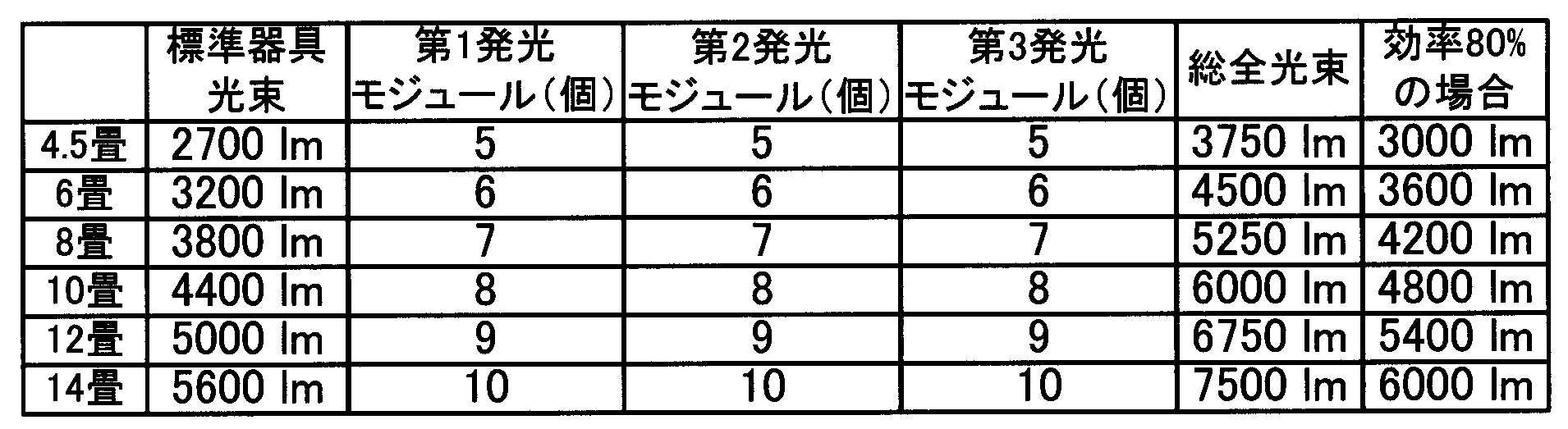
表3に、部屋の大きさ(畳数)に応じた第1~第3発光モジュールの個数等を示している。ここではLEDとして全光束50lmのものを用いた。これにより、第1発光モジュールの総全光束は200lm、第2発光モジュールの総全光束は250lm、第3発光モジュールの総全光束は300lmとなる。
表3に示すように、部屋の大きさが4.5畳の場合、第1~第3発光モジュールを各5個用いると、総全光束は3750lmとなり、80%の効率で3000lmとなり、標準器具光束の2700lmを達成する。
同様に、6畳の場合は第1~第3発光モジュールを各6個用い、8畳の場合は各7個、10畳の場合は各8個、12畳の場合は各9個、14畳の場合は各10個用いると標準器具光束を達成する。
図10に、部屋の大きさが6畳の場合の照明装置の平面図を示す。第1~第3発光モジュール30、40、50がそれぞれ照明装置105の中央を中心とする六角形状の辺を構成するように配置されている。照明装置105の中央には制御基板11が配置されている。ここで、基板が最も長い第3発光モジュール50を外側に、第2発光モジュール40を内側に、基板が最も短い第1発光モジュール30をさらに内側にして並設することで、省スペースで配置することができる。
図示はしないが、同様に4.5畳の場合の照明装置では第1~第3発光モジュールがそれぞれ五角形状に、8畳の場合の照明装置では七角形状に、10畳の場合の照明装置では八角形状に、12畳の場合の照明装置では九角形状に、14畳の場合の照明装置では十角形状に配置される。すなわち、発光モジュール12(第1~第3発光モジュール30、40、50)が種類毎に照明装置の中央を中心とする同形の多角形状の辺を構成するように配置されて構成される。
このように、本実施形態の照明装置によれば、LEDの搭載数が異なる3種類の発光モジュールを適宜組み合わせて用いることにより、発光モジュールの共通化(標準化)を図りつつ、部屋の大きさに応じた必要な光出力に調整することができる。そして、発光モジュールの共通化によって、コストダウン、開発期間の短縮、発光モジュールの在庫削減に繋がる。
<第3実施形態>
第3実施形態は、照明装置に用いる第1発光モジュールの個数と第2発光モジュールの個数とが異なり、第1及び第2発光モジュールの配置形状が異なる点で第1実施形態と異なり、他の構成は第1実施形態と同様である。例えば、第1発光モジュールとしてLED32を5個搭載したもの、第2発光モジュールとしてLED32を6個搭載したものを用いる。
第3実施形態は、照明装置に用いる第1発光モジュールの個数と第2発光モジュールの個数とが異なり、第1及び第2発光モジュールの配置形状が異なる点で第1実施形態と異なり、他の構成は第1実施形態と同様である。例えば、第1発光モジュールとしてLED32を5個搭載したもの、第2発光モジュールとしてLED32を6個搭載したものを用いる。

表4に、部屋の大きさ(畳数)に応じた第1及び第2発光モジュールの個数等を示している。ここではLEDとして全光束70lmのものを用いた。これにより、5個のLEDを搭載する第1発光モジュールの総全光束は350lm、6個のLEDを搭載する第2発光モジュールの総全光束は420lmとなる。
表4に示すように、部屋の大きさが4.5畳の場合、第1発光モジュールを4個、第2発光モジュールを5個用いると、総全光束は3500lmとなり、80%の効率で2800lmとなり、標準器具光束の2700lmを達成する。
同様に、6畳の場合は第1発光モジュールを5個、第2発光モジュールを6個用い、8畳の場合は第1発光モジュールを6個、第2発光モジュールを7個、10畳の場合は第1発光モジュールを7個、第2発光モジュールを8個、12畳の場合は第1発光モジュールを8個、第2発光モジュールを9個、14畳の場合は第1発光モジュールを9個、第2発光モジュールを10個用いると標準器具光束を達成する。
図11に、部屋の大きさが4.5畳の場合の照明装置の平面図を示す。第1発光モジュール30’が照明装置106の中央を中心とする四角形状の辺を構成するように配置され、第2発光モジュール40’が照明装置106の中央を中心とする五角形状の辺を構成するように配置されている。照明装置106の中央には制御基板11が配置されている。ここで、長い方の第2発光モジュール40’を外側に、短い方の第1発光モジュール30’を内側に配置することで、省スペースで配置することができる。
図示はしないが、同様に6畳の場合の照明装置では第1発光モジュールが五角形状、第2発光モジュールが六角形状に、8畳の場合の照明装置では第1発光モジュールが六角形状、第2発光モジュールが七角形状に、10畳の場合の照明装置では第1発光モジュールが七角形状、第2発光モジュールが八角形状に、12畳の場合の照明装置では第1発光モジュールが八角形状、第2発光モジュールが九角形状に、14畳の場合の照明装置では第1発光モジュールが九角形状、第2発光モジュールが十角形状に配置される。すなわち、発光モジュール12(第1及び第2発光モジュール30’、40’)が種類毎に照明装置の中央を中心とする異形の多角形状の辺を構成するように配置されて構成される。
このように、本実施形態の照明装置によれば、LEDの搭載数が異なる2種類の発光モジュールを適宜組み合わせて用いることにより、発光モジュールの共通化(標準化)を図りつつ、部屋の大きさに応じた必要な光出力に調整することができる。そして、発光モジュールの共通化によって、コストダウン、開発期間の短縮、発光モジュールの在庫削減に繋がる。
<第4実施形態>
第4実施形態は、LEDを複数列に搭載した2種類の発光モジュールを用いる点で第1実施形態と異なり、他の構成は第1実施形態と同様である。図12は、第4実施形態の照明装置に用いる第1発光モジュールの平面図、図13は、第4実施形態の照明装置に用いる第2発光モジュールの平面図、図14A及び図14Bは、図12の第1発光モジュールの配線図の一例、図15A及び図15Bは、図13の第2発光モジュールの配線図の一例である。
第4実施形態は、LEDを複数列に搭載した2種類の発光モジュールを用いる点で第1実施形態と異なり、他の構成は第1実施形態と同様である。図12は、第4実施形態の照明装置に用いる第1発光モジュールの平面図、図13は、第4実施形態の照明装置に用いる第2発光モジュールの平面図、図14A及び図14Bは、図12の第1発光モジュールの配線図の一例、図15A及び図15Bは、図13の第2発光モジュールの配線図の一例である。
図12に示すように、第1発光モジュール60は、矩形状の基板61と、基板61上に搭載された8個のLED32と、各LED32の発光面側を覆う光拡散レンズ33と、ドライバ18に接続するためのコネクタ34とを備えている。
各LED32は基板61の長手方向に二列に等間隔のピッチで配設されている。つまり、一列に4個ずつ配置されている。LED32は、図14Aに示すようにコネクタ34に全て直列接続されてもよいし、図14Bに示すようにコネクタ34に一列ずつ直列接続されてもよい。
図13に示すように、第2発光モジュール70は、基板61より長手方向に長い矩形状の基板71と、基板71上に搭載された10個のLED32と、各LED32の発光面側を覆う光拡散レンズ33と、ドライバ18に接続するためのコネクタ34とを備えている。
各LED32は基板71の長手方向に二列に等間隔のピッチで配設されている。このピッチは第1発光モジュール60におけるピッチと同じであってもよいし、異なっていてもよい。LED32は、図15Aに示すように、コネクタ34に全て直列接続されてもよいし、図15Bに示すようにコネクタ34に一列ずつ直列接続されてもよい。
このように、第1発光モジュール60と第2発光モジュール70とは、基板61、71の大きさ(長さ)と、LED32の個数とが異なっている。なお、LED32の個数が異なっていれば基板は同じ大きさであっても構わない。また、LED32の個数や配列数も特に限定はない。また、LED32の配置は千鳥配置や不均等配置であってもよい。さらに、基板61、71の形状は矩形状に限定されることはなく、他の多角形状や円弧状等の曲形状であってもよい。
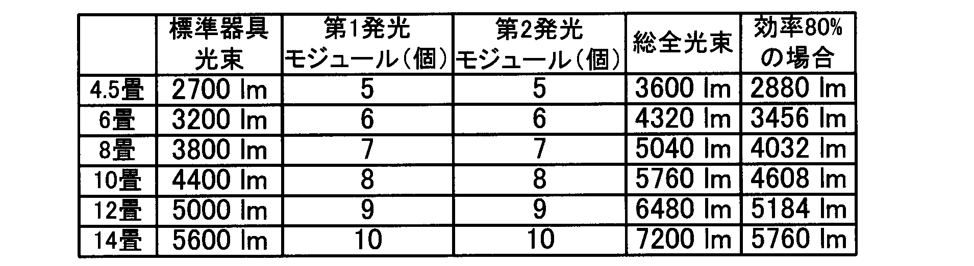
表5に、部屋の大きさ(畳数)に応じた第1及び第2発光モジュールの個数等を示している。ここではLEDとして全光束40lmのものを用いた。これにより、第1発光モジュールの総全光束は320lm、第2発光モジュールの総全光束は400lmとなる。
表5に示すように、部屋の大きさが4.5畳の場合、第1及び第2発光モジュールを各5個用いると、総全光束は3600lmとなり、80%の効率で2880lmとなり、標準器具光束の2700lmを達成する。
同様に、6畳の場合は第1及び第2発光モジュールを各6個用い、8畳の場合は各7個、10畳の場合は各8個、12畳の場合は各9個、14畳の場合は各10個用いると標準器具光束を達成する。
図16に、部屋の大きさが6畳の場合の照明装置の平面図を示す。第1及び第2発光モジュール60、70がそれぞれ照明装置107の中央を中心とする六角形状の辺を構成するように配置されている。照明装置107の中央には制御基板11が配置されている。ここで、長い方の第2発光モジュール70を外側に、短い方の第1発光モジュール60を内側に配置することで、省スペースで配置することができる。
図示はしないが、同様に4.5畳の場合の照明装置では第1及び第2発光モジュールがそれぞれ五角形状に、8畳の場合の照明装置では七角形状に、10畳の場合の照明装置では八角形状に、12畳の場合の照明装置では九角形状に、14畳の場合の照明装置では十角形状に配置される。すなわち、発光モジュール12(第1及び第2発光モジュール60、70)が種類毎に照明装置の中央を中心とする同形の多角形状の辺を構成するように配置されて構成される。
このように、本実施形態の照明装置によれば、LEDの搭載数が異なる2種類の発光モジュールを適宜組み合わせて用いることにより、発光モジュールの共通化(標準化)を図りつつ、部屋の大きさに応じた必要な光出力に調整することができる。そして、発光モジュールの共通化によって、コストダウン、開発期間の短縮、発光モジュールの在庫削減に繋がる。
<第5実施形態>
第5実施形態は、発光モジュールを照明装置の中央付近から半径方向の外側向きに延在するように配置する、いわゆる放射状に配置する点で第1実施形態と異なり、他の構成は第1実施形態と同様である。
第5実施形態は、発光モジュールを照明装置の中央付近から半径方向の外側向きに延在するように配置する、いわゆる放射状に配置する点で第1実施形態と異なり、他の構成は第1実施形態と同様である。
図17に、部屋の大きさが4.5畳の場合の照明装置の平面図を示す。図17に示す照明装置108では、第1及び第2発光モジュール30、40がそれぞれ照明装置108の中央付近から半径方向の外側向きに延在するように放射状に配置されている。照明装置108の中央には制御基板11が配置されている。図17では一対の第1及び第2発光モジュール30、40を並設しているがこの形態に限定されることはなく、例えば、第1及び第2発光モジュール30、40をさらに離間させて別々に放射状に配置してもよい。
このように、本実施形態の照明装置によれば、発光モジュール12(第1及び第2発光モジュール30、40)が照明装置の中央付近から半径方向の外側向きに延在するように配置されて構成される。よって、LEDの搭載数が異なる2種類の発光モジュールを適宜組み合わせて用いることにより、発光モジュールの共通化(標準化)を図りつつ、部屋の大きさに応じた必要な光出力に調整することができる。そして、発光モジュールの共通化によって、コストダウン、開発期間の短縮、発光モジュールの在庫削減に繋がる。
<第6実施形態>
第6実施形態は、発光モジュールを照明装置の中央付近から半径方向以外の外側向きに延在するように配置する、いわゆる風車状に配置する点で第1実施形態と異なり、他の構成は第1実施形態と同様である。
第6実施形態は、発光モジュールを照明装置の中央付近から半径方向以外の外側向きに延在するように配置する、いわゆる風車状に配置する点で第1実施形態と異なり、他の構成は第1実施形態と同様である。
図18に、部屋の大きさが4.5畳の場合の照明装置の平面図を示す。図18に示す照明装置109では、第1及び第2発光モジュール30、40がそれぞれ照明装置109の中央付近から半径方向の外側向きに延在するように放射状に配置されている。照明装置109の中央には制御基板11が配置されている。図18では一対の第1及び第2発光モジュール30、40を並設しているがこの形態に限定されることはなく、例えば、第1及び第2発光モジュール30、40をさらに離間させて別々に風車状に配置してもよい。
このような風車状の配置は、放射状の配置では発光モジュールが長すぎて照明装置内に収まらない場合に有効である。また、風車状の配置は放射状の配置よりも発光モジュールの配置が均等になるので、より均一な照明が得られる。
このように、本実施形態の照明装置によれば、発光モジュール12(第1及び第2発光モジュール30、40)が照明装置の中央付近から半径方向以外の外側向きに延在するように配置されて構成される。よって、LEDの搭載数が異なる2種類の発光モジュールを適宜組み合わせて用いることにより、発光モジュールの共通化(標準化)を図りつつ、部屋の大きさに応じた必要な光出力に調整することができる。そして、発光モジュールの共通化によって、コストダウン、開発期間の短縮、発光モジュールの在庫削減に繋がる。
上記の第5及び第6実施形態ではLED32が等間隔のピッチで配置された発光モジュール30、40を用いて説明したが、他にもLED32のピッチが照明装置の外側に向かって狭くなっていてもよい。図19に、LED32のピッチが徐々に狭くなっている発光モジュール80の一例の平面図を示す。図19では、最も内側となるLED32のピッチを100mmとした場合、外側に向かって100、80、60、50、40mmと徐々に狭くなっている例を示している。
このような発光モジュール80を用いて第5又は第6実施形態の照明装置を得ることにより、発光モジュール同士の間隔が狭い照明装置の中央付近ではLED32の密度を下げ、発光モジュール同士の間隔が広い照明装置の外側付近ではLED32の密度を上げることができ、より均一な照明が得られる。
また、図19では、コネクタ34が基板81の長手方向で内側に配置される端部に設けられている。これにより、第5及び第6実施形態の発光モジュールの配置によれば、コネクタ34を制御基板11に直結又は短い線で接続することが可能となり、接続を簡素化できる。
以下に本発明の実施形態についてまとめる。本発明の一実施形態の照明装置10は、基板上に複数の発光ダイオードを搭載した発光モジュール12を複数備えた照明装置であって、前記発光モジュール12は複数種類あり、種類毎に前記発光ダイオードの搭載数が異なる構成とする。
この構成によれば、発光ダイオードの搭載数が異なる複数種類の発光モジュールを適宜組み合わせて用いることにより、発光モジュールの共通化(標準化)を図りつつ、部屋の大きさに応じた必要な光出力に調整することができる。そして、発光モジュールの共通化によって、コストダウン、開発期間の短縮、発光モジュールの在庫削減に繋がる。
上記の照明装置において、発光モジュールの共通化の観点からは、前記複数種類が3種類以下であることが好ましい。
また上記の照明装置において、発光モジュールの配置を具体化するために、前記複数種類の発光モジュールは、前記基板が種類毎に異なる大きさの矩形状であり、前記発光モジュールは種類毎に照明装置の中央を中心とする多角形状の辺を構成するように配置されることとしてもよい。
また上記の照明装置において、発光モジュールの配置を具体化するために、前記複数種類の発光モジュールは、前記基板が種類毎に異なる大きさの矩形状であり、前記発光モジュールは照明装置の中央付近から半径方向の外側向きに延在することとしてもよい。
また上記の照明装置において、発光モジュールの配置を具体化するために、前記複数種類の発光モジュールは、前記基板が種類毎に異なる大きさの矩形状であり、前記発光モジュールは照明装置の中央付近から半径方向以外の外側向きに延在することとしてもよい。
また上記の半径方向又は半径方向以外の外側向きに発光モジュールを配置する照明装置においては、前記発光モジュールにおいて前記発光ダイオードのピッチが照明装置の外側に向かって狭くなっていることとしてもよい。この構成により、発光モジュール同士の間隔が狭い照明装置の中央付近では発光ダイオードの密度を下げ、発光モジュール同士の間隔が広い照明装置の外側付近では発光ダイオードの密度を上げることができ、より均一な照明が得られる。
また上記の照明装置において、前記発光ダイオードは色温度が異なる2種類からなり、同じ種類の前記発光モジュールには同じ種類の前記発光ダイオードが搭載されることとしてもよい。この構成により、発光モジュールの種類毎に制御すれば、色毎に調光できる。
また上記の照明装置において、均一な出射光を得るために、前記発光ダイオードの発光面側を覆う光拡散レンズを設けることが好ましい。
また上記の照明装置において、前記光拡散レンズは、前記発光ダイオードからの出射光を個別に拡散し、レンズ表面で光強度が均一になる配光特性を有していることが望ましい。
本発明の照明装置は、居室等の天井に取り付けられ、全体に光を照射するシーリングライトをはじめとする各種照明器具に利用することができる。
10、101~109 照明装置
31、41、61、71、81 基板
32 LED(発光ダイオード)
12 発光モジュール
33 光拡散レンズ
31、41、61、71、81 基板
32 LED(発光ダイオード)
12 発光モジュール
33 光拡散レンズ
Claims (5)
- 基板上に複数の発光ダイオードを搭載した発光モジュールを複数備えた照明装置であって、
前記発光モジュールは複数種類あり、種類毎に前記発光ダイオードの搭載数が異なることを特徴とする照明装置。 - 前記複数種類が3種類以下であることを特徴とする請求項1に記載の照明装置。
- 前記複数種類の発光モジュールは、前記基板が種類毎に異なる大きさの矩形状であり、
前記発光モジュールは種類毎に照明装置の中央を中心とする多角形状の辺を構成するように配置されることを特徴とする請求項1又は2に記載の照明装置。 - 前記複数種類の発光モジュールは、前記基板が種類毎に異なる大きさの矩形状であり、
前記発光モジュールは照明装置の中央付近から半径方向の外側向きに延在することを特徴とする請求項1又は2に記載の照明装置。 - 前記複数種類の発光モジュールは、前記基板が種類毎に異なる大きさの矩形状であり、
前記発光モジュールは照明装置の中央付近から半径方向以外の外側向きに延在することを特徴とする請求項1又は2に記載の照明装置。
Applications Claiming Priority (2)
| Application Number | Priority Date | Filing Date | Title |
|---|---|---|---|
| JP2013165913 | 2013-08-09 | ||
| JP2013-165913 | 2013-08-09 |
Publications (1)
| Publication Number | Publication Date |
|---|---|
| WO2015019854A1 true WO2015019854A1 (ja) | 2015-02-12 |
Family
ID=52461193
Family Applications (1)
| Application Number | Title | Priority Date | Filing Date |
|---|---|---|---|
| PCT/JP2014/069511 Ceased WO2015019854A1 (ja) | 2013-08-09 | 2014-07-24 | 照明装置 |
Country Status (1)
| Country | Link |
|---|---|
| WO (1) | WO2015019854A1 (ja) |
Citations (3)
| Publication number | Priority date | Publication date | Assignee | Title |
|---|---|---|---|---|
| JP2011134684A (ja) * | 2009-12-25 | 2011-07-07 | Sharp Corp | 照明装置 |
| JP2012104476A (ja) * | 2010-10-12 | 2012-05-31 | Toshiba Lighting & Technology Corp | 照明装置 |
| JP2012181982A (ja) * | 2011-03-01 | 2012-09-20 | Rohm Co Ltd | Led照明器具 |
-
2014
- 2014-07-24 WO PCT/JP2014/069511 patent/WO2015019854A1/ja not_active Ceased
Patent Citations (3)
| Publication number | Priority date | Publication date | Assignee | Title |
|---|---|---|---|---|
| JP2011134684A (ja) * | 2009-12-25 | 2011-07-07 | Sharp Corp | 照明装置 |
| JP2012104476A (ja) * | 2010-10-12 | 2012-05-31 | Toshiba Lighting & Technology Corp | 照明装置 |
| JP2012181982A (ja) * | 2011-03-01 | 2012-09-20 | Rohm Co Ltd | Led照明器具 |
Similar Documents
| Publication | Publication Date | Title |
|---|---|---|
| CN102714260B (zh) | 包括光混合物的固态照明装置 | |
| US10125971B2 (en) | LED lamp integrated to electric fan | |
| JP6074703B2 (ja) | Led照明装置及びled発光モジュール | |
| JP6128465B2 (ja) | 発光モジュール | |
| JP5696980B2 (ja) | 照明器具 | |
| WO2011144597A2 (en) | A lighting device | |
| US20100254127A1 (en) | LED-based lighting module for emitting white light with easily adjustable color temperature | |
| JP6284079B2 (ja) | 発光装置、照明用光源、および照明装置 | |
| US20150357372A1 (en) | Solid state lighting device including narrow spectrum emitter | |
| JP2004103444A (ja) | 照明器具 | |
| CN204403966U (zh) | 照明器具及辅助光源单元 | |
| US20170077172A1 (en) | Light-emitting device and illumination light source | |
| KR101185253B1 (ko) | 엘이디 조명 장치 | |
| TW201312041A (zh) | 發光裝置以及照明裝置 | |
| JP6074704B2 (ja) | 照明器具 | |
| JP2014130923A (ja) | 発光モジュール、照明装置および照明器具 | |
| JP2013084544A (ja) | 照明装置、照明器具および照明制御システム | |
| JP6460581B2 (ja) | 照明器具 | |
| JP2015170417A (ja) | 光源ユニットおよび照明器具 | |
| JP2015106502A (ja) | 照明装置 | |
| JP2024049680A (ja) | 照明装置及び照明器具 | |
| WO2015019854A1 (ja) | 照明装置 | |
| TW201812207A (zh) | 照明裝置 | |
| KR102556270B1 (ko) | 엘이디 햇빛등 및 엘이디 햇빛등기구 | |
| JP6256528B2 (ja) | 照明器具 |
Legal Events
| Date | Code | Title | Description |
|---|---|---|---|
| 121 | Ep: the epo has been informed by wipo that ep was designated in this application |
Ref document number: 14835077 Country of ref document: EP Kind code of ref document: A1 |
|
| NENP | Non-entry into the national phase |
Ref country code: DE |
|
| NENP | Non-entry into the national phase |
Ref country code: JP |
|
| 122 | Ep: pct application non-entry in european phase |
Ref document number: 14835077 Country of ref document: EP Kind code of ref document: A1 |