WO2015019637A1 - イオン発生装置 - Google Patents
イオン発生装置 Download PDFInfo
- Publication number
- WO2015019637A1 WO2015019637A1 PCT/JP2014/054414 JP2014054414W WO2015019637A1 WO 2015019637 A1 WO2015019637 A1 WO 2015019637A1 JP 2014054414 W JP2014054414 W JP 2014054414W WO 2015019637 A1 WO2015019637 A1 WO 2015019637A1
- Authority
- WO
- WIPO (PCT)
- Prior art keywords
- ion generator
- mask
- user
- housing
- ion
- Prior art date
- Legal status (The legal status is an assumption and is not a legal conclusion. Google has not performed a legal analysis and makes no representation as to the accuracy of the status listed.)
- Ceased
Links
Images







Classifications
-
- H—ELECTRICITY
- H01—ELECTRIC ELEMENTS
- H01T—SPARK GAPS; OVERVOLTAGE ARRESTERS USING SPARK GAPS; SPARKING PLUGS; CORONA DEVICES; GENERATING IONS TO BE INTRODUCED INTO NON-ENCLOSED GASES
- H01T23/00—Apparatus for generating ions to be introduced into non-enclosed gases, e.g. into the atmosphere
-
- A—HUMAN NECESSITIES
- A62—LIFE-SAVING; FIRE-FIGHTING
- A62B—DEVICES, APPARATUS OR METHODS FOR LIFE-SAVING
- A62B18/00—Breathing masks or helmets, e.g. affording protection against chemical agents or for use at high altitudes or incorporating a pump or compressor for reducing the inhalation effort
- A62B18/02—Masks
- A62B18/025—Halfmasks
-
- A—HUMAN NECESSITIES
- A62—LIFE-SAVING; FIRE-FIGHTING
- A62B—DEVICES, APPARATUS OR METHODS FOR LIFE-SAVING
- A62B18/00—Breathing masks or helmets, e.g. affording protection against chemical agents or for use at high altitudes or incorporating a pump or compressor for reducing the inhalation effort
- A62B18/08—Component parts for gas-masks or gas-helmets, e.g. windows, straps, speech transmitters, signal-devices
-
- H—ELECTRICITY
- H01—ELECTRIC ELEMENTS
- H01T—SPARK GAPS; OVERVOLTAGE ARRESTERS USING SPARK GAPS; SPARKING PLUGS; CORONA DEVICES; GENERATING IONS TO BE INTRODUCED INTO NON-ENCLOSED GASES
- H01T19/00—Devices providing for corona discharge
- H01T19/04—Devices providing for corona discharge having pointed electrodes
Definitions
- the present invention relates to an ion generator covered with a mask-like member or the like.
- Patent Document 1 discloses a mask to which an ion generator is attached.
- the mask is pivotally supported so that the first cover and the second cover can be opened and closed on both sides of a receiving portion having a vent hole.
- a mask body made of cloth or the like is attached to the first cover and the receiving portion. When the first cover is closed, the mask body is folded and stored, and when the first cover is opened, the mask body is unfolded.
- a device for attaching the ion generator is provided on the inner surface of the second cover.
- the ion generator is attached to the receiving portion by a brace and generates negative ions.
- the user opens the first cover and the second cover, covers the mouth and nose with the mask body, and wears the mask. Accordingly, breathing is performed through the mask body and the vent hole, and the mask body prevents intrusion of viruses, pollen, dust, and the like from the user's mouth and nose. Also, negative ions generated by the ion generator diffuse into the mask body through the vents and the mask body, and are supplied to the front of the user. Thereby, a user's discomfort by long-term mask wearing can be reduced.
- ions generated by the ion generator flow out from between the opened second cover and the receiving part, and a part of the ions are shielded by the mask body. For this reason, there also exists a problem that the ion supplied in front of a user reduces.
- An object of the present invention is to provide an ion generator that can reduce an economical burden on a user who uses a mask and can reliably supply ions in front of the user.
- an ion generator of the present invention has a casing covered by a mask-like member disposed on the face of a user, and the casing includes an ion generating element that generates ions, and the casing
- the said housing is provided with the protrusion part which protrudes from the circumference
- the present invention is characterized in that, in the ion generator configured as described above, the tip of the protruding portion is formed in a curved surface.
- the present invention is the ion generator configured as described above, wherein the discharge port is formed on a peripheral surface adjacent to the front surface of the housing, and the protruding portion is arranged along the front surface of the housing. To do.
- an element storage member that houses the ion element with the housing disposed on one side with respect to the user's nose and a battery storage member that houses the battery disposed on the other side are connected.
- the housing is provided with a mounting portion for mounting the housing on a mask-like member.
- the present invention is characterized in that in the ion generator configured as described above, there is provided a mounting portion that extends from the casing and is mounted on a face by being hooked on a user's ear.
- the present invention is characterized in that, in the ion generator configured as described above, the battery is embedded by a resin filled in the battery housing member.
- the present invention is characterized in that, in the ion generator configured as described above, a slide-type power switch is provided on the front surface of the casing on the right side from the user side.
- the present invention is characterized in that, in the ion generator configured as described above, a cover member made of a soft member is provided on the outer surface of the casing.
- the present invention is characterized in that, in the ion generating apparatus having the above-described configuration, a light emitting unit that is turned on for a predetermined time by a predetermined operation when the ion generating element is driven is provided.
- the casing covered by the mask attached to the user's face is provided with a protruding portion protruding from the periphery of the discharge port.
- a commercially available inexpensive mask ion generator such as a disposable mask can be attached to release ions into the mask.
- the mask which deteriorated by use can be replaced
- the mask prevents the mask from covering the entire discharge port by the protruding portion, and ions can be reliably supplied in front of the user. Accordingly, it is possible to prevent the sterilization effect and the deodorizing effect from being reduced by ions.
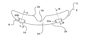
- the perspective view which shows the ion generator of 1st Embodiment of this invention.
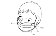
- the figure which shows the state equipped with the ion generator of 1st Embodiment of this invention.
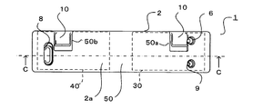
- the top view which shows the ion generator of 1st Embodiment of this invention.
- the front view which shows the ion generator of 1st Embodiment of this invention.
- the right view which shows the ion generator of 1st Embodiment of this invention.
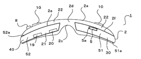
- the bottom view which shows the ion generator of 1st Embodiment of this invention.
- Front view of the second embodiment of the present invention Longitudinal sectional view of the second embodiment of the present invention
- the left view which shows the ion generator of 3rd Embodiment of this invention.
- the figure which shows the state equipped with the ion generator of 3rd Embodiment of this invention.
- the front view which shows the ion generator of 3rd Embodiment of this invention.
- the right view which shows the ion generator of 3rd Embodiment of this invention.
- FIG. 1 is a perspective view of an ion generator 1 according to the first embodiment.
- FIG. 2 shows a state in which the ion generator 1 is mounted.
- the ion generator 1 is provided with a clip-shaped mounting portion 10 having elasticity at the top of the front surface 2 a of the housing 2.
- the mounting unit 10 is sandwiched between the upper ends of the mask 100 that is mounted on the face with the ear hooks 100 a on both ears of the user, and the ion generator 1 is attached to the mask 100.
- the front surface of the ion generator 1 is covered with the mask 100 and is arranged in the space between the mask 100 and the face.
- the mounting portion 10 may sandwich the upper end of the mask 100 using a magnet.
- the mounting portion 10 may be formed in a pin shape or a hook shape and may be attached to the ion generator 1 through the upper portion of the mask 100.
- the mask 100 may have a shape that is bent into a pleat shape.
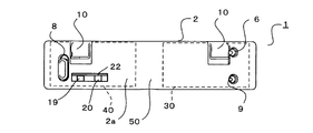
- FIG. 3 to 6 show a top view, a front view, a right side view, and a bottom view of the ion generator 1.
- FIG. The housing 2 is formed by a cover member 50 made of a soft member, a battery housing member 30 made of a hard member covered with the cover member 50 and partially exposed, and an element housing member 40.
- a soft resin such as silicone or elastomer, a sponge-like resin, or the like can be used as the soft member for forming the cover member 50.
- a hard resin such as polypropylene can be used as a hard material for forming the battery storage member 30 and the element storage member 40.
- the battery storage member 30 and the element storage member 40 are press-fitted through openings 51a and 52a opened on the lower surface of the flexible cover member 50. Thereby, the battery storage member 30 and the element storage member 40 are stored in the storage portions 51 and 52 provided in the cover member 50, and the battery storage member 30 and the element storage member 40 are exposed from the openings 51a and 52a.
- the front surface 2a and the back surface 2b of the housing 2 are curved so as to protrude forward, and a concave portion 2c that comes into contact with the user's nose is provided at the center of the back surface 2b. Since the cover member 50 has flexibility, the concave portion 2c can be deformed into a shape along the user's nose, and the burden of contact with the user is reduced.
- the user's face and the cover member 50 can be brought into close contact with each other, and the gap between the housing 2 and the user can be eliminated.
- the cover member 50 may have a pleat structure like goggles so that the user's face and the cover member 50 are substantially in close contact with each other.
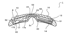
- FIG. 7 and 8 show a cross-sectional view taken along the line CC in FIG. 4 and a cross-sectional view taken along the line BB in FIG.
- a communication portion 53 that communicates the storage portions 51 and 52 is provided at the center of the cover member 50.
- the communication portion 53 is provided with a cable 24, one of the cables 24 is connected to a drive circuit unit 13 described later, and the other is connected to an ion generating element 17 that generates ions.
- a bent portion 25 is formed in front of the communication portion 53. Since the bent portion 25 has flexibility, it can be deformed into a shape along the user's nose.
- the bent portion 25 may be formed using a hinge member.
- the battery storage member 30 includes a front case 30a and a back case 30b.
- a mounting portion 10 is provided on the front surface of the front case 30a, and the mounting portion 10 is exposed from the front surface 2a through a hole 50a opened at the top of the front surface 2a of the cover member 50.
- the front case 30 a and the back case 30 b are engaged to store the battery 14 and the drive circuit unit 13 in the battery storage member 30.
- the battery 14 is composed of a rechargeable lithium ion battery or the like, and supplies power to each part of the ion generator 1.
- the battery housing member 30 is filled with a resin 26 such as urethane, whereby the battery 14 is embedded in the resin 26.
- the drive circuit unit 13 drives each part of the ion generator 1 and is connected to the battery 14, the charging unit 5, the switches 8 and 9, the LED 6, and the ion generating element 17.
- the charging unit 5 is arranged on the bottom surface 2d of the housing 2 and has an insertion port 5a (see FIG. 6).
- a USB terminal and an AC plug are connected to the charging unit 5 through the insertion port 5a, and power necessary for charging the battery 14 is supplied.
- the switch 8 is provided on the right side (see FIG. 1) of the front surface 2a of the housing 2 when viewed from the user side.
- the switch 8 is formed in a sliding manner, and switches the power of the ion generator 1 on and off.
- the switch 9 is provided on the left side (see FIG. 1) of the front surface 2a of the housing 2 when viewed from the user side.
- the switch 9 is formed by a push type, and the operation state of the ion generator 1 can be confirmed by turning on an LED (light emitting unit) 6 described later by operating the switch 9.
- the configuration may be such that only one switch is provided, and the function of switching the power ON / OFF of the ion generator 1 and the function of turning on the LED 6 for confirming the driving state are combined.
- the operation can be separated according to whether the switch is pressed for a long time or when it is pressed for a short time.
- the operation can be separated according to the slide distance.
- each operation can be separated depending on whether the switch is pressed or when the switch is slid.
- the LED 6 is provided in the vicinity (see FIG. 1) of the left mounting portion 10 when viewed from the user side.
- the LED 6 maintains the extinguished state when the driving of the ion generator 1 is started by the operation of the switch 8.
- the switch 9 When the switch 9 is pressed, the LED 6 is lit for several seconds. Thereby, the user can recognize the driving state of the ion generator 1. Further, since the LED 6 is turned off during normal use, it is possible to avoid annoyance by the light from the LED 6 reaching the eyes of the user.
- the LED 6 when the power is supplied from the charging unit 5 to the ion generator 1, the LED 6 is turned on. Thereby, it can confirm that the ion generator 1 is charged correctly. Power is supplied from the charging unit 5 to the ion generator 1, and the LED 6 is turned off when fully charged. Further, when the ion generating element 17 needs to be replaced, the LED 6 is always lit with a warning color different from the normal in an abnormal state.
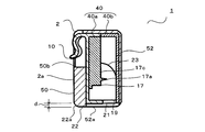
- FIG. 9 is a cross-sectional view taken along the line AA in FIG.
- the element housing member 40 includes a front case 40a and a back case 40b.
- the front case 40 a and the back case 40 b are engaged to store the ion generating element 17 in the element storing member 40.
- the mounting portion 10 is provided on the front surface of the front case 40a, and the mounting portion 10 is exposed to the front surface 2a through a hole 50b (see FIG. 1) opened in the upper portion of the front surface 2a of the cover member 50.
- the discharge ports 19 and 20 are each formed in a rectangular shape on the peripheral surface adjacent to the front surface 2 a of the housing 2.
- the discharge ports 19 and 20 are provided on the lower surface of the back surface case 40b so as to face the opening 52a.
- the ion generating element 17 is provided with a pair of discharge electrodes 17a and 17b formed in a needle shape toward the rear. Thereby, the discharge electrodes 17a and 17b are arranged facing the discharge ports 19 and 20, respectively.
- a guide portion 23 is provided above the discharge electrode 17a (the same applies to the discharge electrode 17b).
- the guide part 23 is formed in a curved surface convex upward by the back surface case 40b, and can easily guide ions generated at the discharge electrode 17a to the discharge port 19.
- a positive voltage is applied to the discharge electrode 17a, and hydrogen ions generated by ionization of water molecules in the air by corona discharge combine with moisture in the air to form positive ions mainly composed of H + (H 2 O) m. Is generated.
- a negative voltage is applied to the discharge electrode 17b, and oxygen ions generated by ionization of oxygen molecules or water molecules in the air by corona discharge are combined with moisture in the air to form mainly O 2 ⁇ (H 2 O) n.
- Negative ions consisting of Here, m and n are arbitrary natural numbers.
- H + (H 2 O) m and O 2 ⁇ (H 2 O) n aggregate around the surface of airborne bacteria and odorous components and surround them.
- active species [ ⁇ OH] hydroxyl radical
- H 2 O 2 hydrogen peroxide
- m ′ and n ′ are arbitrary natural numbers.
- a partition 21 (see FIG. 6) is provided between the discharge port 19 and the discharge port 20.
- the partition part 21 can reduce annihilation due to collision between positive ions and negative ions discharged from the discharge ports 19 and 20.
- the periphery of the opening 52a of the cover member 50 protrudes downward with respect to the lower surfaces of the element storage member 40 and the battery storage member 30, and both sides are open.
- the cover member 50 forms a protruding portion 22 that protrudes from the periphery of the discharge ports 19 and 20 and opens a part in the circumferential direction of the discharge ports 19 and 20.
- the protrusion 22 protrudes downward from the discharge ports 19 and 20 by a distance d and extends in the left-right direction along the front surface 2a of the housing 2.
- the front end portion 22a of the protruding portion 22 is formed with a curved surface on the front surface 2a side. Moreover, you may form the side surface and rear surface side of the front-end
- the user fixes the ion generator 1 to the upper end of the mask 100 using the mounting portion 10 (see FIG. 2).
- the mask 100 is worn on the user's face by an ear hook 100a provided at the end.
- the mask 100 may be an inexpensive disposable mask 100 that is generally available and commercially available.
- the arrangement of the protrusion 22 is not particularly limited as long as it is around the discharge ports 19 and 20, but it is more preferable that the protrusion 22 extends along the front surface 2a of the housing 2 as shown in the present embodiment. Thereby, when the mask 100 arranged in front of the housing 2 is bent rearward, the mask 100 is arranged on the protruding portion 22 and can reliably prevent the discharge ports 19 and 20 from being blocked.
- the inner surface of the mask 100 and the front surface 2a of the housing 2 slide.
- the front surface 2a side of the tip 22a of the protrusion 22 is formed into a curved surface, the mask 100 can be easily aligned while preventing the mask 100 and the housing 2 from being caught.
- the ion generator 1 removed from the mask 100 is removed, and the ion generator 1 is attached to a new mask 100. For this reason, a user's economical burden is reduced.
- the housing 2 covered with the mask 100 attached to the user's face includes the protruding portions 22 protruding from the periphery of the discharge ports 19 and 20.
- the ion generator 1 can be attached to a commercially available inexpensive mask 100 such as a disposable mask to release ions into the mask 100.
- the mask 100 which deteriorated by use can be replaced
- the protrusion 100 prevents the mask 100 from covering the entire discharge ports 19 and 20, and can reliably supply ions in front of the user. Accordingly, it is possible to prevent the sterilization effect and the deodorizing effect from being reduced by ions.
- the inner surface of the mask 100 can be prevented from being caught by the ion generator 1, and the mask 100 can be easily aligned. .
- the discharge ports 19 and 20 are formed in the surrounding surface adjacent to the front surface 2a of the housing
- an element housing member 40 that houses the ion generating element 17 with the housing 2 disposed on one side with respect to the user's nose, and a battery housing member 30 that houses the battery 14 disposed on the other side.
- a mounting portion 10 that is formed by connecting and mounting the housing 2 to the mask 100 is provided on the front surface 2 a of the housing 2.
- the battery 14 is embedded in the resin 26 filled in the battery housing member 30, the weight including the inside of the battery housing member 30 and the weight including the inside of the element housing member 40 can be balanced. Thereby, the usability of the ion generator 1 can be improved. In addition, the heat dissipation of the battery 14 can be improved by the resin 26, and leakage of the battery 14 when it is damaged can be prevented.
- the switch 8 is provided on the right side of the front surface 2a of the housing 2 when viewed from the user side, the switch 8 is prevented from coming into contact with the user's face, and uncomfortable feeling when the ion generator 1 is mounted is reduced. Can do. In addition, a right-handed user can easily turn the ion generator 1 on and off.
- the cover member 50 is made of a soft resin member, it is deformed along the shape of the user's face. Thereby, the wearing feeling of the ion generator 1 can be improved. The burden on the user is reduced, and the user's face and the cover member 50 are in close contact with each other, so that the outflow of ions can be reduced, and the sterilization effect and the deodorization effect due to the ions can be prevented. Can do.
- the driving state of the ion generator 1 can be easily determined, and the light of the LED 6 can be seen by the user. Annoying can be avoided by reaching.
- FIG. 10 has shown the front view of the ion generator 1 of 2nd Embodiment.
- FIG. 11 is a longitudinal sectional view (cross-sectional view taken along the line AA in FIG. 3) of the ion generator 1 which is the same as that in FIG. 9 described above.
- the same reference numerals are given to the same parts as those of the first embodiment shown in FIGS.
- This embodiment differs in arrangement
- the element storage member 40 is press-fitted into the storage portion 52 provided in the cover member 50 through the opening 52a, and includes a front case 40a and a back case 40b.
- the front case 40a and the back case 40b are engaged with each other to house the ion generating element 17.
- the ion generating element 17 is installed in the back case 40b, and the discharge electrodes 17a and 17b (see FIG. 7) of the ion generating element 17 are arranged to face forward.
- a guide portion 23 having an upward convex curved surface is provided in front of the discharge electrodes 17a and 17b.
- Discharge ports 19 and 20 and a protrusion 22 are provided on the front surface 2 a of the housing 2.
- the discharge ports 19 and 20 extend forward from the storage portion 52 of the cover member 50 and are formed by through holes 52b.
- the through hole 52b is arranged to face the through hole 40c provided in the lower part of the surface case 40a.
- the protruding portion 22 is formed to extend in the left-right direction, and is provided above the discharge ports 19 and 20 so as to protrude from the surface of the cover member 50. Moreover, the front-end
- the protrusion part 22 may be provided above and below the discharge ports 19 and 20, and may be provided only in one of the upper part or the lower part.
- the protrusion part 22 when the protrusion part 22 is provided in the upper part of the discharge outlets 19 and 20, when the ion generator 1 is attached to the mask 100, the lower part and both sides of the discharge outlets 19 and 20 will be open
- the protruding portion 22 protrudes forward from the discharge port 19 by a distance d. Thereby, obstruction
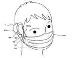
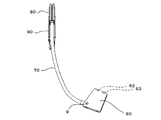
- FIG. 12 shows a left side view of the ion generator 1 of the third embodiment.
- FIG. 13 shows a state where the ion generator 1 is mounted.
- the ion generator 1 has a housing 60 and a mounting part 70.
- An ion generating element 17 (see FIG. 16) that generates ions is arranged in the housing 60.
- the mounting unit 70 includes a connection unit 75, a battery storage unit 90, and a holding unit 80.
- the connecting portion 75 extends from the housing 60 and is connected to the holding portion 80 so as to hold the bent state desired by the user.
- the connection part 75 may have a stretching property.
- the holding part 80 is formed in a U-shape, has flexibility, and can be held in one ear of the user.
- connection part 75 is bent, the housing 60 is arranged in front of the user, and the mask 100 is mounted. Thereby, the housing
- the battery storage unit 90 stores the battery 14 and the drive circuit unit 13 (see FIG. 7).
- a switch 91 (see FIG. 12) for turning the power of the ion generator 1 on and off is disposed on the side surface of the battery storage unit 90.
- FIG. 16 is a cross-sectional view taken along the line FF in FIG.
- the housing 60 is formed by a front case 61a and a back case 61b made of a hard member.
- the ion generating element 17 is installed in the back surface case 61b.
- Discharge electrodes 17a and 17b are arranged on the ion generating element 17 so as to face the front surface case 61a.
- a guide portion 66 is provided in front of the discharge electrodes 17a and 17b.
- the guide part 66 is formed in a curved surface convex forward. Thereby, ions generated at the discharge electrodes 17 a and 17 b can be easily guided to the discharge ports 62 and 63.
- a partition portion 64 (see FIG. 15) is provided between the discharge port 62 and the discharge port 63.
- the partition part 64 can reduce annihilation due to collision between positive ions and negative ions discharged from the discharge ports 62 and 63.
- a protrusion 65 is provided in front of the discharge ports 62 and 63.
- the protrusion 65 protrudes laterally from the discharge port 62 by a distance d, and is formed to extend in the vertical direction along the front surface 60 a of the housing 60.
- the tip 65a of the protrusion 65 has a curved surface on the front surface 60a side.
- the user uses the mounting portion 70 to fix to one ear (see FIG. 13) and wears the mask 100.
- the mask 100 may be an inexpensive disposable mask 100 that is generally commercially available.
- the protruding portion 65 protrudes around the discharge ports 62 and 63, it is possible to prevent the discharge ports 62 and 63 from being blocked by the mask 100. Thereby, ion can be reliably supplied to a user's surface.
- the arrangement of the protrusion 65 is not particularly limited as long as it is around the discharge ports 62 and 63, but it is more preferable that the protrusion 65 extends along the front surface 60a of the housing 60 as shown in the present embodiment. Thereby, obstruction
- an attachment portion 70 is provided that extends from the housing 60 and is attached to the user's ear to attach the housing 60 to the face.
- the ion generator 1 which discharge
- the projecting portion 65 is arranged along the front surface 60a of the housing 60, it is possible to reliably prevent the discharge ports 62 and 63 from being blocked by the mask 100 covering the front surface 60a.
- the ion generator 1 is covered with the mask 100, but may be covered with a neck warmer or the like. That is, the same effect can be obtained when the ion generator 1 is covered with a mask-like member disposed on the user's face.
- the present invention can be used for an ion generator covered with a mask-like member or the like.
Landscapes
- Health & Medical Sciences (AREA)
- Pulmonology (AREA)
- General Health & Medical Sciences (AREA)
- Business, Economics & Management (AREA)
- Emergency Management (AREA)
- Life Sciences & Earth Sciences (AREA)
- Zoology (AREA)
- Respiratory Apparatuses And Protective Means (AREA)
- Disinfection, Sterilisation Or Deodorisation Of Air (AREA)
Abstract
マスクを使用するユーザに対して経済的負担を軽減するとともに、イオンをユーザの面前に確実に供給できるイオン発生装置を提供する。ユーザの顔面に配されるマスク状部材100により覆われる筐体2を有し、筺体2はイオンを発生するイオン発生素子17を備え、筐体2に設けた吐出口19、20を介してイオンを放出するイオン発生装置1において、筺体2は吐出口19、20の周囲から突出する突出部22を備える。
Description
本発明は、マスク状部材等によって覆われるイオン発生装置に関する。
特許文献1にはイオン発生装置が取り付けられるマスクが開示される。このマスクは通気孔を有する受け部の両面にそれぞれ第1カバー及び第2カバーが開閉可能に枢支される。第1カバー及び受け部には布等により形成されたマスク体が取り付けられる。第1カバーを閉じるとマスク体が畳んで収納され、第1カバーを開くとマスク体が展開される。
第2カバーの内面にはイオン発生装置を取り付ける装具が設けられる。イオン発生装置は装具により受け部に面して取り付けられ、マイナスイオンを発生する。
上記構成のマスクにおいて、ユーザは第1カバー及び第2カバーを開き、マスク体により口や鼻を覆ってマスクを装着する。これにより、マスク体及び通気孔を介して呼吸を行い、マスク体によってユーザの口や鼻からのウィルス、花粉、塵埃等の侵入が防止される。また、イオン発生装置で発生したマイナスイオンは通気孔及びマスク体を介してマスク体の内部に拡散し、ユーザの面前に供給される。これにより、長期のマスク装着によるユーザの不快感を低減することができる。
しかしながら、上記のイオン発生装置は第2カバーに設けられた装具により取り付けられるため、マスクの構造が複雑になる。このため、マスクが高価になり、マスク体の損傷等によってマスクを交換するユーザの経済的な負担が大きくなる問題があった。
また、イオン発生装置で発生したイオンが開かれた第2カバーと受け部との間から流出するとともに、イオンの一部がマスク体で遮蔽される。このため、ユーザの面前に供給されるイオンが減少する問題もあった。
本発明は、マスクを使用するユーザに対して経済的負担を軽減するとともに、イオンをユーザの面前に確実に供給できるイオン発生装置を提供することを目的とする。
上記目的を達成するために本発明のイオン発生装置は、ユーザの顔面に配されるマスク状部材により覆われる筐体を有し、前記筺体はイオンを発生するイオン発生素子を備え、前記筐体に設けた吐出口を介してイオンを放出するイオン発生装置において、前記筺体は前記吐出口の周囲から突出する突出部を備えることを特徴とする。
また本発明は、上記構成のイオン発生装置において、前記突出部の先端部を曲面に形成したことを特徴とする。
また本発明は、上記構成のイオン発生装置において、前記吐出口が前記筐体の前面に隣接した周面に形成され、前記突出部が前記筐体の前面に沿って配されることを特徴とする。
また本発明は、前記筐体がユーザの鼻に対して一側方に配してイオン素子を収納する素子収納部材と、他側方に配してバッテリを収納するバッテリ収納部材とを連結して形成され、
前記筐体をマスク状部材に装着する装着部を前記筐体に設けたことを特徴とする。
前記筐体をマスク状部材に装着する装着部を前記筐体に設けたことを特徴とする。
また本発明は、上記構成のイオン発生装置において、前記筐体から延出されるとともにユーザの耳に掛けて前記筐体を顔面に装着する装着部を設けたことを特徴とする。
また本発明は、上記構成のイオン発生装置において、前記バッテリ収納部材内に充填した樹脂により前記バッテリが埋設されることを特徴とする。
また本発明は、上記構成のイオン発生装置において、ユーザ側から右側の前記筐体の前面にスライド式の電源スイッチを設けたことを特徴とする。
また本発明は、上記構成のイオン発生装置において、前記筐体の外面には軟質部材から成るカバー部材が設けられていることを特徴とする。
また本発明は、上記構成のイオン発生装置において、前記イオン発生素子の駆動時に所定の操作により所定時間点灯した後に消灯する発光部を備えたことを特徴とする。
本発明によると、ユーザの顔面に装着されるマスクにより覆われる筺体は吐出口の周囲から突出する突出部を備える。このため、使い捨てマスク等の市販の安価なマスクイオン発生装置を装着してマスク内にイオンを放出することができる。このため、使用により劣化したマスクを交換でき、ユーザの経済的な負担を軽減してマスク内の殺菌や消臭を行うことができる。
また、突出部によりマスクが吐出口全体を覆うことを防止し、イオンをユーザの面前に確実に供給することができる。従って、イオンによる殺菌効果や消臭効果の低下を防止することができる。
以下に本発明の実施形態を図面を参照して説明する。図1は第1実施形態のイオン発生装置1の斜視図を示している。また、図2はイオン発生装置1の装着状態を示している。
イオン発生装置1は筐体2の前面2aの上部に弾性を有したクリップ形状の装着部10が設けられている。ユーザの両耳に耳掛け部100aを掛けて顔面に装着されるマスク100の上端に装着部10が挟まれ、イオン発生装置1がマスク100に取り付けられている。これにより、イオン発生装置1は前面をマスク100に覆われ、マスク100と顔面との間の空間内に配置されている。
装着部10はマグネットを用いてマスク100の上端を挟んでもよい。また、装着部10をピン形状やホック形状に形成してマスク100の上部を貫通してイオン発生装置1に取り付けてもよい。尚、マスク100はプリーツ状に折り曲げられた形状であってもよい。
図3~図6はイオン発生装置1の上面図、正面図、右側面図及び底面図を示している。筐体2は軟質部材から成るカバー部材50と、カバー部材50により覆われて一部を露出した硬質部材から成るバッテリ収納部材30、素子収納部材40とによって形成される。
カバー部材50を形成する軟質部材として、シリコーン、エラストマ等の軟質樹脂や、スポンジ状の樹脂等を用いることができる。バッテリ収納部材30、素子収納部材40を形成する硬質材料として、ポリプロピレン等の硬質樹脂を用いることができる。
バッテリ収納部材30、素子収納部材40は可撓性を有するカバー部材50の下面に開口した開口部51a、52aを介して圧入される。これにより、カバー部材50に設けた収納部51、52内にバッテリ収納部材30、素子収納部材40が収納され、開口部51a、52aからバッテリ収納部材30、素子収納部材40が露出する。
筐体2の前面2a及び背面2bは前方に突出するように湾曲し、背面2bの中央部にはユーザの鼻に当接する凹部2cが設けられる。カバー部材50が可撓性を有するため、凹部2cをユーザの鼻に沿った形状に変形させることができるともに、ユーザへの当接の負担を軽減する。
さらに、ユーザの顔面とカバー部材50とを略密着させ、筐体2とユーザとの隙間を無くすことができる。なお、カバー部材50はゴーグルのようにひだ構造を有して ユーザの顔面とカバー部材50とを略密着させてもよい。
図7、図8は図4のC-C断面図、図3のB-B断面図を示している。
カバー部材50の中央部には収納部51、52を連通する連通部53が設けられている。連通部53にはケーブル24が設けられており、ケーブル24の一方は後述する駆動回路ユニット13と接続し、他方はイオンを発生するイオン発生素子17と接続する。
連通部53の前方には屈曲部25が形成されている。屈曲部25は可撓性を有するため、ユーザの鼻に沿った形状に変形させることができる。また屈曲部25はヒンジ部材を用いて形成してもよい。
バッテリ収納部材30は表面ケース30a及び裏面ケース30bからなる。表面ケース30aの前面には装着部10が設けられ、カバー部材50の前面2a上部に開口した穴部50aを介して装着部10が前面2aから露出している。
表面ケース30aと裏面ケース30bとは係合してバッテリ収納部材30の内部にバッテリ14、駆動回路ユニット13を収納する。バッテリ14は充電可能なリチウムイオン電池などからなり、イオン発生装置1の各部に電源を供給する。また、バッテリ収納部材30内にはウレタン等の樹脂26が充填され、これによりバッテリ14が樹脂26に埋設されている。
駆動回路ユニット13はイオン発生装置1の各部を駆動し、バッテリ14、充電部5、スイッチ8、9、LED6及びイオン発生素子17に接続されている。
充電部5は筐体2の底面2dに配され、挿入口5a(図6参照)を有している。充電部5には挿入口5aを介してUSB端子やACプラグ(いずれも不図示)が接続され、バッテリ14の充電に必要な電源が供給される。
スイッチ8は筐体2の前面2aのユーザ側から見て右側(図1参照)に設けられている。スイッチ8はスライド式に形成され、イオン発生装置1の電源のON、OFFを切り替える。
スイッチ9は筐体2の前面2aのユーザ側から見て左側(図1参照)に設けられている。スイッチ9はプッシュ式により形成され、スイッチ9の操作により後述するLED(発光部)6を点灯してイオン発生装置1の駆動状況を確認できる。
スイッチは1つのみ設けてあって、イオン発生装置1の電源ON、OFFを切り替える機能と駆動状況を確認するためのLED6を点灯させる機能とを兼ね備える構成であってもよい。プッシュスイッチで構成される場合はスイッチを長押しする場合と、短時間押す場合とで動作を切り分けることができる。スライドスイッチで構成される場合はスライド距離によって動作を切り分けることができる。また、プッシュスイッチとスライドスイッチとを組み合わせた1つのスイッチで構成される場合は、スイッチを押した場合とスライドさせた場合とでそれぞれの動作を切り分けることができる。
LED6はユーザ側から見て左側の装着部10の近傍(図1参照)に設けられている。LED6はスイッチ8の操作によってイオン発生装置1の駆動を開始した状態で消灯状態を維持する。そして、スイッチ9を押下すると、LED6が数秒間点灯する。これにより、ユーザはイオン発生装置1の駆動状態を認識することができる。また、通常使用時にLED6が消灯されているため、LED6の光がユーザの目に届くことにより煩わしさを回避することができる。
また、充電部5からイオン発生装置1に電源が供給されていると、LED6は点灯する。これにより、イオン発生装置1が正しく充電されていることを確認できる。充電部5からイオン発生装置1に電源が供給され、満充電時にはLED6は消灯する。また、イオン発生素子17の交換が必要な場合等、異常状態ではLED6は通常と異なる警告色で常時点灯する。
図9は図3のA-A断面図を示している。素子収納部材40は表面ケース40a及び裏面ケース40bからなる。表面ケース40aと裏面ケース40bとは係合して、素子収納部材40の内部にイオン発生素子17を収納する。表面ケース40aの前面には装着部10が設けられ、カバー部材50の前面2a上部に開口した穴部50b(図1参照)を介して装着部10が前面2aに露出している。
吐出口19、20は筐体2の前面2aに隣接した周面にそれぞれ矩形状に形成されている。これにより、裏面ケース40bの下面には吐出口19、20(図6参照)が開口部52aに対向して設けられている。
イオン発生素子17には後方に向って針状に形成された一対の放電電極17a、17bが設けられている。これにより、放電電極17a、17bが吐出口19、20に臨んで配されている。
放電電極17a(放電電極17bも同様)の上方には案内部23が設けられている。案内部23は裏面ケース40bにより上に凸の曲面に形成され、放電電極17aで発生するイオンを吐出口19へ容易に導くことができる。
放電電極17aには正電圧が印加され、コロナ放電により空気中の水分子が電離して生成される水素イオンが空気中の水分と結合して主としてH+(H2O)mから成るプラスイオンを発生する。放電電極17bには負電圧が印加され、コロナ放電により空気中の酸素分子または水分子が電離して生成される酸素イオンが空気中の水分と結合して主としてO2
-(H2O)nから成るマイナスイオンを発生する。ここで、m、nは任意の自然数である。H+(H2O)m及びO2
-(H2O)nは空気中の浮遊菌や臭い成分の表面で凝集してこれらを取り囲む。
そして、式(1)~(3)に示すように、衝突により活性種である[・OH](水酸基ラジカル)やH2O2(過酸化水素)を微生物等の表面上で凝集生成して浮遊菌や臭い成分を破壊する。ここで、m’、n’は任意の自然数である。
H+(H2O)m+O2
-(H2O)n
→・OH+1/2O2+(m+n)H2O ・・・(1)
H+(H2O)m+H+(H2O)m’+O2 -(H2O)n+O2 -(H2O)n’
→ 2・OH+O2+(m+m'+n+n')H2O ・・・(2)
H+(H2O)m+H+(H2O)m’+O2 -(H2O)n+O2 -(H2O)n’
→ H2O2+O2+(m+m'+n+n')H2O ・・・(3)
→・OH+1/2O2+(m+n)H2O ・・・(1)
H+(H2O)m+H+(H2O)m’+O2 -(H2O)n+O2 -(H2O)n’
→ 2・OH+O2+(m+m'+n+n')H2O ・・・(2)
H+(H2O)m+H+(H2O)m’+O2 -(H2O)n+O2 -(H2O)n’
→ H2O2+O2+(m+m'+n+n')H2O ・・・(3)
吐出口19と吐出口20との間には仕切部21(図6参照)が設けられている。仕切部21により、吐出口19、20から放出されるプラスイオンとマイナスイオンとの衝突による消滅を低減することができる。
カバー部材50の開口部52aの周囲は素子収納部材40及びバッテリ収納部材30の下面に対して下方に突出し、両側方が開放されている。これにより、吐出口19、20の周囲から突出して吐出口19、20の周方向の一部を開放した突出部22がカバー部材50によって形成される。突出部22は吐出口19、20から距離dだけ下方に突出し、筐体2の前面2aに沿って左右方向に延びて設けられている。
突出部22の先端部22aは前面2a側を曲面に形成されている。また、先端部22aの側面や後面側も曲面に形成してもよい。なお、吐出口20の周面に配される突出部22も同様に形成されている。
上記構成のイオン発生装置1において、ユーザは装着部10を用いてマスク100の上端にイオン発生装置1を固定する(図2参照)。マスク100は端部に設けられる耳掛け部100aによってユーザの顔面に装着される。尚、マスク100は一般で市販されている安価な使い捨てのマスク100でよい。
ユーザがスイッチ8を操作してイオン発生装置1が駆動されると、放電電極17a、17bにより生成されるプラスイオン及びマイナスイオンが吐出口19、20を介して下方に放出される。これにより、マスク100内にプラスイオン及びマイナスイオンが拡散して除菌や臭いの除去を行うことができる。
この時、吐出口19、20の周囲には突出部22が突出するため、マスク100による吐出口19、20の閉塞を防止することができる。これにより、イオンをユーザの面前に確実に供給することができる。
突出部22は吐出口19、20の周囲であれば特に配置を限定されないが、本実施形態に示すように筐体2の前面2aに沿って延びるとより望ましい。これにより、筐体2の前方に配されるマスク100が後方に折れ曲がった際に突出部22上に配され、吐出口19、20の閉塞を確実に防止するこができる。
また、顔面に装着されたマスク100を上下方向に位置合わせする際に、マスク100の内面と筐体2の前面2aとが摺動する。この時、突出部22の先端部22aの前面2a側が曲面に形成されているため、マスク100と筐体2との引っ掛かりを防止して容易にマスク100の位置合わせすることができる。
使用によりマスク100の劣化や損傷が生じると、マスク100から取り外したイオン発生装置1を取り外し、新しいマスク100にイオン発生装置1を取り付ける。このため、ユーザの経済的な負担が軽減される。
本実施形態によると、ユーザの顔面に装着されるマスク100により覆われる筐体2は吐出口19、20の周囲から突出する突出部22を備える。このため、使い捨てマスク等の市販の安価なマスク100にイオン発生装置1を装着してマスク100内にイオンを放出することができる。このため、使用により劣化したマスク100を交換でき、ユーザの経済的な負担を軽減してマスク100内の殺菌や消臭を行うことができる。
また、突出部22によりマスク100が吐出口19、20全体を覆うことを防止し、イオンをユーザの面前に確実に供給することができる。従って、イオンによる殺菌効果や消臭効果の低下を防止することができる。
また、突出部22の先端部22aの前面2a側を曲面に形成したため、マスク100の内面がイオン発生装置1に引っかかることを防止することができ、マスク100の位置合わせを容易に行うことができる。
また、吐出口19、20が筐体2の前面2aに隣接した周面に形成され、突出部22が筐体2の前面2aに沿って配されるため、前面2aを覆うマスク100による吐出口19、20の閉塞を確実に防止することができる。
また、筐体2がユーザの鼻に対して一側方に配してイオン発生素子17を収納する素子収納部材40と、他側方に配してバッテリ14を収納するバッテリ収納部材30とを連結して形成され、筐体2をマスク100に装着する装着部10を筐体2の前面2aに設けている。これにより、使い捨てマスク等の市販の安価なマスク100に取り付けてマスク100の内部にイオンを放出するイオン発生装置1を容易に実現することができる。
また、バッテリ収納部材30内に充填した樹脂26内にバッテリ14を埋設したため、バッテリ収納部材30の内部を含む重量と素子収納部材40の内部を含む重量とをバランスさせることができる。これにより、イオン発生装置1の使用性を向上することができる。また、樹脂26によってバッテリ14の放熱性を向上できるとともに、バッテリ14の損傷時の漏電等を防止することができる。
また、筐体2の前面2aのユーザ側から見て右側にスイッチ8を設けたため、スイッチ8がユーザの顔面に当接することを防止し、イオン発生装置1の装着時の不快感を低下させることができる。また、右利きのユーザによって容易にイオン発生装置1の電源のON、OFF操作を行うことができる。
また、カバー部材50は軟質な樹脂部材から成っているため、ユーザの顔面の形状に沿って変形する。これにより、イオン発生装置1の装着感を向上することができる。ユーザへの当接の負担を軽減するとともに、ユーザの顔面とカバー部材50とが略密着するため、イオンの流出を低減することができ、イオンによる殺菌効果や消臭効果の低減を防止することができる。
また、イオン発生装置1の駆動時に所定の操作により所定時間点灯した後に消灯するLED6を備えたため、イオン発生装置1の駆動状態を容易に判別することができるとともに、LED6の光がユーザの目に届くことにより煩わしさを回避することができる。
<第2実施形態>
次に、図10は第2実施形態のイオン発生装置1の正面図を示している。また、図11はイオン発生装置1の前述の図9と同じ縦断面図(図3のA-A断面図)を示している。説明の便宜上、前述の図1~図9に示す第1実施形態と同様の部分には同一の符号を付している。本実施形態は第1実施形態に対して突出部22及び吐出口19、20の配置が異なっている。その他の部分は第1実施形態と同様である。
次に、図10は第2実施形態のイオン発生装置1の正面図を示している。また、図11はイオン発生装置1の前述の図9と同じ縦断面図(図3のA-A断面図)を示している。説明の便宜上、前述の図1~図9に示す第1実施形態と同様の部分には同一の符号を付している。本実施形態は第1実施形態に対して突出部22及び吐出口19、20の配置が異なっている。その他の部分は第1実施形態と同様である。
素子収納部材40はカバー部材50に設けた収納部52に開口部52aを介して圧入され、表面ケース40a及び裏面ケース40bからなる。表面ケース40aと裏面ケース40bとは係合し、イオン発生素子17を収納する。
イオン発生素子17は裏面ケース40bに設置され、イオン発生素子17の放電電極17a、17b(図7参照)は前方を向くように配されている。放電電極17a、17bの前方には上に凸の曲面からなる案内部23が設けられている。
筐体2の前面2aには吐出口19、20及び突出部22が設けられている。吐出口19、20はカバー部材50の収納部52から前方に延びて貫通孔52bにより形成される。貫通孔52bは表面ケース40aの下部に設けた貫通孔40cに対向して配される。
突出部22は左右方向に延びて形成され、カバー部材50の表面から突出して吐出口19、20の上部に設けられている。また突出部22の先端部22aは曲面(上下面が曲面)により形成されている。これにより、突出部22は吐出口19、20の周方向の一部を開放して形成されている。
なお、突出部22は吐出口19、20の上下に設けてもよく、上部もしくは下部の一方のみに設けられていてもよい。なお、突出部22が吐出口19、20の上部に設けられていると、イオン発生装置1をマスク100に取り付けられた際、吐出口19、20の下部及び両側部が開放される。これにより、顔面側に多くイオンを流入させることができるのでより好ましい。
また、突出部22は吐出口19から距離dだけ前方に突出している。これにより、イオン発生装置1の前方に配されるマスク100による吐出口19、20の閉塞を防止することができる。
本実施形態においても、第1実施形態と同様の効果を奏することができる。
<第3実施形態>
次に、第3実施形態のイオン発生装置1について説明する。説明の便宜上、前述の図1~図9に示す第1実施形態と同様の部分には同一の符号を付している。図12は第3実施形態のイオン発生装置1の左側面図を示している。また、図13はイオン発生装置1の装着状態を示している。
次に、第3実施形態のイオン発生装置1について説明する。説明の便宜上、前述の図1~図9に示す第1実施形態と同様の部分には同一の符号を付している。図12は第3実施形態のイオン発生装置1の左側面図を示している。また、図13はイオン発生装置1の装着状態を示している。
イオン発生装置1は筐体60及び装着部70を有している。筐体60内にはイオンを発生するイオン発生素子17(図16参照)が配されている。
装着部70は接続部75、バッテリ収納部90および保持部80を有している。接続部75は筐体60から延びて保持部80に接続し、ユーザが所望する屈曲した状態を保持できるように形成されている。また接続部75は伸縮性を有してもよい。保持部80はU字状に形成され、可撓性を有してユーザの片耳に保持することができる。
接続部75を屈曲して筐体60をユーザの面前に配し、マスク100が装着される。これにより、筐体60は前面60aをマスク100に覆われ、マスク100と顔面との間の空間内に配置されている。
図14、図15はイオン発生装置1の正面図、右側面図を示している。バッテリ収納部90はバッテリ14、駆動回路ユニット13(図7参照)を収納している。バッテリ収納部90の側面にはイオン発生装置1の電源のON、OFFを行うスイッチ91(図12参照)が配されている。
筐体60の側面60bには吐出口62、63が開口している。図16は図15のF-F断面図を示している。筐体60は硬質部材から成る表面ケース61aと裏面ケース61bとによって形成されている。裏面ケース61bにはイオン発生素子17が設置され、イオン発生素子17には放電電極17a、17bが表面ケース61aに対向して配されている。
放電電極17a、17bの前方には案内部66が設けられている。案内部66は前方に凸の曲面に形成されている。これにより、放電電極17a、17bで発生するイオンを吐出口62、63へ容易に導くことができる。
吐出口62と吐出口63との間には仕切部64(図15参照)が設けられている。仕切部64により、吐出口62、63から放出されるプラスイオンとマイナスイオンとの衝突による消滅を低減することができる。
吐出口62、63の前方には突出部65が設けられている。突出部65は吐出口62から距離dだけ側方に突出し、筐体60の前面60aに沿って上下方向に延びて形成されている。突出部65の先端部65aは前面60a側を曲面に形成している。
上記構成のイオン発生装置1において、ユーザは装着部70を用いて片耳に固定(図13参照)し、マスク100を装着する。マスク100は一般で市販されている安価な使い捨てのマスク100でよい。
ユーザがスイッチ91を操作してイオン発生装置1が駆動されると、放電電極17a、17bにより生成されるプラスイオン及びマイナスイオンが吐出口62、63を介して側方に放出される。これにより、マスク100内はプラスイオン及びマイナスイオンが拡散して除菌や臭いの除去を行うことができる。
この時、吐出口62、63の周囲には突出部65が突出するため、マスク100による吐出口62、63の閉塞を防止することができる。これにより、イオンをユーザの面前に確実に供給することができる。
突出部65は吐出口62、63の周囲であれば特に配置を限定されないが、本実施形態に示すように筐体60の前面60aに沿って延びるとより望ましい。これにより、前面60aを覆うマスク100による吐出口62、63の閉塞を確実に防止することができる。
本実施形態によると、第1実施形態と同様の効果を得ることができる。また、筐体60から延出されるとともにユーザの耳に掛けて筐体60を顔面に装着する装着部70を設けている。これにより、使い捨てマスク等の市販の安価なマスク100を用いてマスク100の内部にイオンを放出するイオン発生装置1を容易に実現することができる。
また、突出部65が筐体60の前面60aに沿って配されるため、前面60aを覆うマスク100による吐出口62、63の閉塞を確実に防止することができる。
第1~第3実施形態において、イオン発生装置1がマスク100に覆われるが、ネックウォーマー等により覆われてもよい。即ち、イオン発生装置1がユーザの顔面に配されるマスク状部材に覆われている場合に、同様の効果を得ることができる。
今回開示された実施の形態はすべての点で例示であって制限的なものではないと考えられるべきである。本発明の範囲は、上記した説明ではなく、請求の範囲によって示され、請求の範囲と均等の意味および範囲内でのすべての変更が含まれることが意図される。
本発明によると、マスク状部材等によって覆われるイオン発生装置に利用することができる。
1 イオン発生装置
2 筐体
2a 前面
2b 後面
2c 凹部
2d 底面
5 充電部
5a 挿入口
6 LED(発光部)
8 スイッチ
9 スイッチ
10 装着部
13 駆動回路ユニット
14 バッテリ
17 イオン発生素子
17a、17b 放電電極
19 吐出口
20 吐出口
21 仕切部
22 突出部
22a 先端部
23 案内部
24 ケーブル
25 屈曲部
26 樹脂
30 バッテリ収納部材
30a 表面ケース
30b 裏面ケース
40 素子収納部材
40a 表面ケース
40b 裏面ケース
40c 貫通穴
50 カバー部材
50a 穴部
50b 穴部
51 収納部
51a 開口部
52 収納部
52a 開口部
52b 貫通穴
53 連通部
60 筐体
60a 前面
60b 側面
61 素子収納部
61a 表面ケース
61b 裏面ケース
62 吐出口
63 吐出口
64 仕切部
65 突出部
66 案内部
70 装着部
75 接続部
80 保持部
90 バッテリ収納部
91 スイッチ
100 マスク
100a 耳かけ部
2 筐体
2a 前面
2b 後面
2c 凹部
2d 底面
5 充電部
5a 挿入口
6 LED(発光部)
8 スイッチ
9 スイッチ
10 装着部
13 駆動回路ユニット
14 バッテリ
17 イオン発生素子
17a、17b 放電電極
19 吐出口
20 吐出口
21 仕切部
22 突出部
22a 先端部
23 案内部
24 ケーブル
25 屈曲部
26 樹脂
30 バッテリ収納部材
30a 表面ケース
30b 裏面ケース
40 素子収納部材
40a 表面ケース
40b 裏面ケース
40c 貫通穴
50 カバー部材
50a 穴部
50b 穴部
51 収納部
51a 開口部
52 収納部
52a 開口部
52b 貫通穴
53 連通部
60 筐体
60a 前面
60b 側面
61 素子収納部
61a 表面ケース
61b 裏面ケース
62 吐出口
63 吐出口
64 仕切部
65 突出部
66 案内部
70 装着部
75 接続部
80 保持部
90 バッテリ収納部
91 スイッチ
100 マスク
100a 耳かけ部
Claims (5)
- ユーザの顔面に配されるマスク状部材により覆われる筐体を有し、前記筺体はイオンを発生するイオン発生素子を備え、前記筐体に設けた吐出口を介してイオンを放出するイオン発生装置において、
前記筺体は前記吐出口の周囲から突出する突出部を備えることを特徴とするイオン発生装置。 - 前記突出部の先端部を曲面に形成したことを特徴とする請求項1に記載のイオン発生装置。
- 前記吐出口が前記筐体の前面に隣接した周面に形成され、前記突出部が前記筐体の前面に沿って配されることを特徴とする請求項1又は2に記載のイオン発生装置。
- 前記筐体がユーザの鼻に対して一側方に配してイオン発生素子を収納する素子収納部材と、他側方に配してバッテリを収納するバッテリ収納部材とを連結して形成され、
前記筐体をマスク状部材に装着する装着部を前記筐体の前面に設けたことを特徴とする請求項1~3のいずれかに記載のイオン発生装置。 - 前記筐体から延出されるとともにユーザの耳に掛けて前記筐体を顔面に装着する装着部を設けたことを特徴とする請求項1~3のいずれかに記載のイオン発生装置。
Priority Applications (1)
| Application Number | Priority Date | Filing Date | Title |
|---|---|---|---|
| CN201490000883.XU CN205319512U (zh) | 2013-08-09 | 2014-02-25 | 离子发生装置 |
Applications Claiming Priority (2)
| Application Number | Priority Date | Filing Date | Title |
|---|---|---|---|
| JP2013-165912 | 2013-08-09 | ||
| JP2013165912A JP2015035341A (ja) | 2013-08-09 | 2013-08-09 | イオン発生装置 |
Publications (1)
| Publication Number | Publication Date |
|---|---|
| WO2015019637A1 true WO2015019637A1 (ja) | 2015-02-12 |
Family
ID=52460986
Family Applications (1)
| Application Number | Title | Priority Date | Filing Date |
|---|---|---|---|
| PCT/JP2014/054414 Ceased WO2015019637A1 (ja) | 2013-08-09 | 2014-02-25 | イオン発生装置 |
Country Status (3)
| Country | Link |
|---|---|
| JP (1) | JP2015035341A (ja) |
| CN (1) | CN205319512U (ja) |
| WO (1) | WO2015019637A1 (ja) |
Cited By (1)
| Publication number | Priority date | Publication date | Assignee | Title |
|---|---|---|---|---|
| EP3943163A1 (en) * | 2020-07-20 | 2022-01-26 | Make Great Sales Limited | Removable mask airflow device |
Families Citing this family (2)
| Publication number | Priority date | Publication date | Assignee | Title |
|---|---|---|---|---|
| JP7623559B2 (ja) | 2020-09-18 | 2025-01-29 | 株式会社アーティストデザイン | マスクの形状保持具 |
| KR102275011B1 (ko) * | 2021-04-12 | 2021-07-07 | 장석운 | 다기능 공기 청정 마스크 |
Citations (2)
| Publication number | Priority date | Publication date | Assignee | Title |
|---|---|---|---|---|
| JP2005038731A (ja) * | 2003-07-16 | 2005-02-10 | Alpha Technotool:Kk | 携帯用マイナスイオン発生装置 |
| JP2007151823A (ja) * | 2005-12-05 | 2007-06-21 | Koji Ito | 携帯型空調装置のアタッチメントならびに携帯型空調装置 |
-
2013
- 2013-08-09 JP JP2013165912A patent/JP2015035341A/ja active Pending
-
2014
- 2014-02-25 CN CN201490000883.XU patent/CN205319512U/zh not_active Expired - Fee Related
- 2014-02-25 WO PCT/JP2014/054414 patent/WO2015019637A1/ja not_active Ceased
Patent Citations (2)
| Publication number | Priority date | Publication date | Assignee | Title |
|---|---|---|---|---|
| JP2005038731A (ja) * | 2003-07-16 | 2005-02-10 | Alpha Technotool:Kk | 携帯用マイナスイオン発生装置 |
| JP2007151823A (ja) * | 2005-12-05 | 2007-06-21 | Koji Ito | 携帯型空調装置のアタッチメントならびに携帯型空調装置 |
Cited By (1)
| Publication number | Priority date | Publication date | Assignee | Title |
|---|---|---|---|---|
| EP3943163A1 (en) * | 2020-07-20 | 2022-01-26 | Make Great Sales Limited | Removable mask airflow device |
Also Published As
| Publication number | Publication date |
|---|---|
| JP2015035341A (ja) | 2015-02-19 |
| CN205319512U (zh) | 2016-06-15 |
Similar Documents
| Publication | Publication Date | Title |
|---|---|---|
| JP7705890B2 (ja) | ウェアラブル空気清浄機、ノズルアセンブリ及びウェアラブル空気送給装置 | |
| KR101616707B1 (ko) | Led 마스크 | |
| KR101988303B1 (ko) | 헤어 관리 장치 | |
| US7123733B1 (en) | Auditory treatment device | |
| KR101735703B1 (ko) | 안면과 두피를 복합 관리하는 엘이디 마스크 장치 | |
| KR20230010753A (ko) | 웨어러블 공기 정화기 | |
| KR101578800B1 (ko) | 휴대용 산소마스크 | |
| KR102193162B1 (ko) | 마스크용 김서림방지 및 호흡이 편한 장치 | |
| KR101714193B1 (ko) | 마스크 | |
| KR101832903B1 (ko) | 이탈이 방지되는 탈모 치료 헬멧 | |
| WO2015019637A1 (ja) | イオン発生装置 | |
| JP2019072191A (ja) | ヘアードライヤー | |
| US20240108891A1 (en) | Portable beauty device and charging dock | |
| US20240366973A1 (en) | Head wearable air purifier | |
| KR102204824B1 (ko) | 헤어 상태 분석 기능을 갖는 헤어 관리 장치 | |
| KR102177366B1 (ko) | 소독 기능을 갖는 헤어 관리 장치의 크래들 장치 | |
| JP2010187767A (ja) | 美容装置 | |
| JP5833470B2 (ja) | イオン発生装置 | |
| JP2018089139A (ja) | 鼻腔カニューラ | |
| KR102179915B1 (ko) | 수술용 마스크 | |
| KR102177368B1 (ko) | 헤어 관리 장치의 제어 방법 | |
| WO2022102513A1 (ja) | 水素供給用ゴーグル及びその水素供給用ゴーグルを用いた眼球への水素投与ユニット | |
| KR102177367B1 (ko) | 통신 기능을 갖는 헤어 관리 장치의 크래들 장치 | |
| KR102205417B1 (ko) | 온도 제어 기능을 갖는 헤어 관리 장치 | |
| KR102204822B1 (ko) | 헤어 관리 장치 세트 |
Legal Events
| Date | Code | Title | Description |
|---|---|---|---|
| 121 | Ep: the epo has been informed by wipo that ep was designated in this application |
Ref document number: 14834208 Country of ref document: EP Kind code of ref document: A1 |
|
| NENP | Non-entry into the national phase |
Ref country code: DE |
|
| 122 | Ep: pct application non-entry in european phase |
Ref document number: 14834208 Country of ref document: EP Kind code of ref document: A1 |