WO2015015933A1 - 熱交換器および熱交換システム - Google Patents
熱交換器および熱交換システム Download PDFInfo
- Publication number
- WO2015015933A1 WO2015015933A1 PCT/JP2014/066111 JP2014066111W WO2015015933A1 WO 2015015933 A1 WO2015015933 A1 WO 2015015933A1 JP 2014066111 W JP2014066111 W JP 2014066111W WO 2015015933 A1 WO2015015933 A1 WO 2015015933A1
- Authority
- WO
- WIPO (PCT)
- Prior art keywords
- heat exchange
- flow path
- exchange liquid
- heat exchanger
- heat
- Prior art date
- Legal status (The legal status is an assumption and is not a legal conclusion. Google has not performed a legal analysis and makes no representation as to the accuracy of the status listed.)
- Ceased
Links
Images







Classifications
-
- F—MECHANICAL ENGINEERING; LIGHTING; HEATING; WEAPONS; BLASTING
- F28—HEAT EXCHANGE IN GENERAL
- F28D—HEAT-EXCHANGE APPARATUS, NOT PROVIDED FOR IN ANOTHER SUBCLASS, IN WHICH THE HEAT-EXCHANGE MEDIA DO NOT COME INTO DIRECT CONTACT
- F28D3/00—Heat-exchange apparatus having stationary conduit assemblies for one heat-exchange medium only, the media being in contact with different sides of the conduit wall, in which the other heat-exchange medium flows in a continuous film, or trickles freely, over the conduits
-
- A—HUMAN NECESSITIES
- A47—FURNITURE; DOMESTIC ARTICLES OR APPLIANCES; COFFEE MILLS; SPICE MILLS; SUCTION CLEANERS IN GENERAL
- A47J—KITCHEN EQUIPMENT; COFFEE MILLS; SPICE MILLS; APPARATUS FOR MAKING BEVERAGES
- A47J31/00—Apparatus for making beverages
- A47J31/44—Parts or details or accessories of beverage-making apparatus
- A47J31/60—Cleaning devices
-
- F—MECHANICAL ENGINEERING; LIGHTING; HEATING; WEAPONS; BLASTING
- F28—HEAT EXCHANGE IN GENERAL
- F28D—HEAT-EXCHANGE APPARATUS, NOT PROVIDED FOR IN ANOTHER SUBCLASS, IN WHICH THE HEAT-EXCHANGE MEDIA DO NOT COME INTO DIRECT CONTACT
- F28D7/00—Heat-exchange apparatus having stationary tubular conduit assemblies for both heat-exchange media, the media being in contact with different sides of a conduit wall
- F28D7/10—Heat-exchange apparatus having stationary tubular conduit assemblies for both heat-exchange media, the media being in contact with different sides of a conduit wall the conduits being arranged one within the other, e.g. concentrically
- F28D7/106—Heat-exchange apparatus having stationary tubular conduit assemblies for both heat-exchange media, the media being in contact with different sides of a conduit wall the conduits being arranged one within the other, e.g. concentrically consisting of two coaxial conduits or modules of two coaxial conduits
-
- F—MECHANICAL ENGINEERING; LIGHTING; HEATING; WEAPONS; BLASTING
- F28—HEAT EXCHANGE IN GENERAL
- F28F—DETAILS OF HEAT-EXCHANGE AND HEAT-TRANSFER APPARATUS, OF GENERAL APPLICATION
- F28F25/00—Component parts of trickle coolers
- F28F25/02—Component parts of trickle coolers for distributing, circulating, and accumulating liquid
-
- F—MECHANICAL ENGINEERING; LIGHTING; HEATING; WEAPONS; BLASTING
- F28—HEAT EXCHANGE IN GENERAL
- F28F—DETAILS OF HEAT-EXCHANGE AND HEAT-TRANSFER APPARATUS, OF GENERAL APPLICATION
- F28F9/00—Casings; Header boxes; Auxiliary supports for elements; Auxiliary members within casings
- F28F9/22—Arrangements for directing heat-exchange media into successive compartments, e.g. arrangements of guide plates
- F28F2009/222—Particular guide plates, baffles or deflectors, e.g. having particular orientation relative to an elongated casing or conduit
- F28F2009/228—Oblique partitions
-
- F—MECHANICAL ENGINEERING; LIGHTING; HEATING; WEAPONS; BLASTING
- F28—HEAT EXCHANGE IN GENERAL
- F28F—DETAILS OF HEAT-EXCHANGE AND HEAT-TRANSFER APPARATUS, OF GENERAL APPLICATION
- F28F25/00—Component parts of trickle coolers
- F28F2025/005—Liquid collection; Liquid treatment; Liquid recirculation; Addition of make-up liquid
Definitions
- the present invention relates to a heat exchanger and a heat exchange system for exchanging heat between fluids, and more particularly to a heat exchanger and a heat exchange system for cooling a high-temperature liquid for beverage with a low-temperature fluid.
- holding means for swingably holding a baby bottle is provided in the baby bottle cooling container, and the baby bottle cooling container is swung.
- a configuration is disclosed in which the baby bottle is swung, whereby the milk in the baby bottle is stirred, and the refrigerant is stirred by swinging the baby bottle.
- Patent Document 2 discloses that water heated to near the boiling temperature is stored in a water tank before heating. An apparatus is shown that can be cooled by being led into a pipe passing through the pipe to make a water cooler.
- Patent Document 3 a fluid is allowed to flow on a working surface that exhibits a curvature that substantially matches at least one logarithmic curve according to the “golden section”, and heat is exchanged between the working surface and the fluid. An exchanger is described.
- Japanese Patent Publication No. 2011-229594 (published on November 17, 2011) Japanese Patent No. 3029732 (issued April 4, 2000) Japanese Patent Gazette No. 2005-513410 (published on May 12, 2005)
- this method has a problem in convenience, for example, it is necessary to cool the cooler in the refrigerator for several hours in advance.
- it is necessary to feed milk every few hours and also at night, so it is necessary to avoid cumbersome work such as cooling the cooler as much as possible. Is desirable.
- Patent Document 2 it is difficult to remove the pipe through which the liquid flows and clean the inside of the pipe, and also to visually check the inside of the pipe. For this reason, it is difficult to maintain a hygienic beverage such as coffee and tea, not just milk after conditioning.
- Patent Document 3 since the liquid flow path has a complicated shape, it is difficult to clean the flow path and confirm the state of the flow path, making it difficult to manage hygiene.
- the present invention has been made in view of the above problems, and an object of the present invention is to realize a heat exchanger and a heat exchange system capable of easily cleaning a fluid flow path and confirming the state of the fluid flow path. There is to do.
- a heat exchanger performs heat exchange between a heat exchange liquid and a heat exchange fluid, and heat that adjusts the temperature of the heat exchange liquid.
- the exchanger is provided with a flow path forming portion substantially in the shape of a conical portion of a funnel, and the flow path forming portion is formed in a substantially spiral shape on the inner peripheral surface of the flow path forming portion. It has a heat exchange liquid channel that is a channel for the exchange liquid, and the heat exchange liquid channel is a groove-like channel in which a vertically upper portion is released.
- the heat exchange liquid can be hygienically adjusted to a desired temperature.
- FIGS. 1 to 12 An embodiment of the present invention will be described with reference to FIGS. 1 to 12 as follows.
- a heat exchanger for cooling milk adjusted to 70 ° C. with water to an appropriate temperature (about 40 degrees) will be described.
- the liquid to be cooled, such as the milk is referred to as a heat exchange liquid
- the liquid, such as the water, for cooling the heat exchange liquid is referred to as a heat exchange liquid (heat exchange fluid).
- the heat exchange liquid is not limited to milk and may be any liquid such as a beverage liquid.
- the heat exchange liquid is not limited to water, and may be any liquid.
- any gas may be used as the heat exchange liquid instead of a liquid.
- tap water suitable for drinking it is preferable to use tap water suitable for drinking as the heat exchange liquid.
- the heat exchange liquid does not come into contact with the heat exchange liquid or the like that directly touches the mouth, but when the heat exchanger is washed, the heat exchange liquid flow path is changed to the heat exchange liquid flow path. Therefore, it is better to use a sanitary liquid that does not have any hygienic problems.
- the heat exchanger may heat the heat exchange liquid with the heat exchange liquid.
- FIG. 1 is a diagram illustrating an example of a configuration of a heat exchange system according to an embodiment of the present invention.
- the heat exchange system 100 includes a heat exchanger 1, a tank (storage unit) 2, and a pump (supply unit) 3.
- the heat exchanger 1 performs heat exchange between the heat exchange liquid and the heat exchange liquid.
- the heat exchanger 1 is connected to the tank 2 and the pump 3 respectively.
- the tank 2 stores the heat exchange liquid 120.
- the pump 3 sends out the heat exchange liquid 120 stored in the tank 2 to the heat exchanger 1.
- the heat exchange liquid 120 circulates through the tank 2, the pump 3 and the heat exchanger 1. Specifically, the heat exchange liquid 120 is sent from the tank 2 to the heat exchanger 1 by the pump 3, passes through the flow path disposed in the heat exchanger 1, and the heat exchange liquid 110. After heat exchange, it flows into the tank 2.
- a heat exchange liquid outlet 4 is disposed at the top of the heat exchanger 1, and a heat exchange liquid 110 that receives heat exchange from the heat exchange liquid outlet 4 is poured toward the heat exchanger 1.
- the flow path of the heat exchange liquid 110 is formed in a shape having an open upper surface, and can receive the heat exchange liquid 110 poured from above.
- the heat exchange liquid 110 flows down from the top to the bottom in the flow path of the heat exchanger 1, and during this time, heat exchange with the heat exchange liquid 120 is performed. Thereafter, the heat exchange liquid 110 flows out of the heat exchanger 1 and is poured into the cup 5. If the heat exchange liquid 110 is milk for infants, a baby bottle may be placed directly instead of the cup 5.
- the heat exchange amount can be changed by changing the feed flow rate of the heat exchange liquid 120 with the pump 3, it is possible to change the temperature of the heat exchange liquid 110 flowing out from the heat exchanger 1. .
- the temperature of the heat exchange liquid 110 changes in a direction approaching the temperature of the heat exchange liquid 120, and when the flow rate is decreased, the temperature changes in a direction away from the heat exchange liquid 110. More specifically, when the feed flow rate of the heat exchange liquid 120 is increased in order to cool the high temperature heat exchange liquid 110 by the low temperature heat exchange liquid 120, the heat exchange that flows out from the heat exchanger 1 is performed.
- the temperature of the liquid 110 decreases and the feed flow rate is decreased, the temperature of the heat exchange liquid 110 flowing out of the heat exchanger 1 increases.
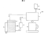
- FIG. 2 is a diagram illustrating an example of a configuration of another heat exchange system. 2 is different from the heat exchange system 100 shown in FIG. 1 in that an auxiliary cooling mechanism 6 is installed in the tank 2.
- the auxiliary cooling mechanism 6 is an air cooling mechanism using a fan, a cooling mechanism using a Peltier element, a heat dissipation mechanism using fins, or the like.
- the heat exchange liquid 110 When the heat exchange liquid 110 is cooled by the heat exchange liquid 120, the temperature of the heat exchange liquid 120 rises due to heat exchange with the heat exchange liquid 110. In particular, the heat exchange liquid 110 When the amount (relative to the heat exchange liquid 120) is large, or the temperature of the heat exchange liquid 110 is very high, the temperature rise of the heat exchange liquid 120 becomes large. If the temperature of the heat exchange liquid 120 rises, the temperature difference from the heat exchange liquid 110 becomes small, and the amount of heat exchange decreases.
- the temperature of the heat exchange liquid 120 that has risen due to the heat exchange in the heat exchanger 1 can be lowered. Therefore, the temperature of the heat exchange liquid 120 can be maintained at a low temperature, and a decrease in the heat exchange amount can be suppressed. Furthermore, the amount of the heat exchange liquid 120 as cooling water stored in the tank 2 can be reduced.
- FIG. 3 is a diagram illustrating an example of the configuration of another heat exchange system.
- the heat exchange system 102 shown in FIG. 3 is different from the heat exchange system 100 shown in FIG. 1 in that a heater 7 is installed in the tank 2.
- the heat exchange system 102 shown in FIG. 3 warms the low temperature heat exchange liquid 110 using the high temperature heat exchange liquid 120.
- Refrigerating liquid stored in a refrigerator or the like is generally heated by a microwave oven.
- heating by a microwave oven is non-uniform and a hot hot spot is locally generated.
- Heating by the heat exchange system 102 is suitable for use scenes where such hot spots are to be avoided, for example, when reheating the milk after milk preparation.
- FIG. 4 is a perspective view showing the external appearance of the flow path forming portion 11
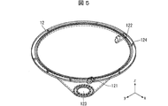
- FIG. 5 is a perspective view showing the external appearance of the flow path cover portion 12.
- the flow path forming part 11 and the flow path cover part 12 have substantially the same shape as the conical part of the funnel.
- the flow path forming part 11 and the flow path cover part 12 have a substantially truncated cone shape whose upper surface and bottom surface are open.
- the central axis of the conical portion is taken as the Z axis
- the axes orthogonal to the central axis of the conical portion are taken as the X axis and the Y axis.
- the flow path forming portion 11 includes a conical portion 115 which is a main body portion, an inner surface rib 111 formed on the inner peripheral surface of the conical portion 115, and an outer surface rib 112 formed on the outer peripheral surface of the conical portion.
- the inner rib 111 extends substantially vertically upward (the positive direction of the Z axis) from the inner peripheral surface of the conical portion 115.
- the outer surface rib 112 extends from the outer peripheral surface of the conical portion 115 in a direction substantially parallel to the XY plane.
- the flow path cover 12 includes a heat exchange liquid inlet 121 that is an inlet of the heat exchange liquid 120 supplied by the pump 3, and a heat exchange liquid that is discharged from the heat exchanger 1.
- a heat exchange liquid outlet 122 which is an outlet of 120;
- the heat exchange liquid inlet 121 is arranged at the lower part of the flow path cover part 12, and the heat exchange liquid outlet 122 is arranged at the upper part of the flow path cover part 12.
- the present invention is not limited to this, and the heat exchange liquid inlet 121 may be disposed in the upper part of the flow path cover part 12, and the heat exchange liquid outlet 122 may be disposed in the lower part of the flow path cover part 12.
- the heat exchanger 1 is configured such that the flow path forming part 11 is accommodated on the inner peripheral surface side of the flow path cover part 12 and the flow path forming part 11 and the flow path cover part 12 are engaged.
- a discharge port for the heat exchange liquid 110 of the heat exchanger 1 is formed by the lower opening 113 of the flow path forming part 11 and the lower opening 123 of the flow path cover part 12.
- the flow path forming part 11 and the flow path cover part 12 are fixed to each other through a fastening through the fastening through hole 114 provided in the flow path forming part 11 and the fastening through hole 124 provided in the flow path cover part 12.
- the first flow path which is the flow path of the heat exchange liquid 110
- the first flow path has a groove shape in which a vertical upper portion is released.
- the second flow path which is the flow path of the heat exchange liquid 120
- the second flow path is formed by the outer peripheral surface of the conical portion 115 of the flow path forming portion 11, the outer surface rib 112, and the inner peripheral surface of the flow path cover portion 12.
- the second flow path is a space (closed flow path) closed by the outer peripheral surface of the conical part 115, the outer surface rib 112, and the inner peripheral surface of the flow path cover part 12.
- the flow path forming part 11 and the flow path cover part 12 have a simple shape that does not have a troublesome undercut or the like and is easy to be given a draft when molding, so that the flow path forming the heat exchanger 1 is formed. Since the part 11 and the flow path cover part 12 can be easily produced by molding, the manufacturing cost can be reduced.
- FIG. 6 is a cross-sectional view of the heat exchanger 1 according to the first embodiment.
- the inner rib 111 is formed in a spiral shape from the upper edge of the inner peripheral surface of the conical portion 115 of the flow path forming portion 11 to the lower center. That is, the 1st flow path in Example 1 is a spiral shape. Further, the outer rib 112 is formed in a spiral shape from the upper edge of the outer peripheral surface of the conical portion 115 of the flow path forming portion 11 to the lower center. That is, the 2nd flow path in Example 1 is a helical shape.
- the first flow path has a spiral shape with the central axis of the conical portion formed along the inner peripheral surface of the flow path forming portion 11.
- the second flow path has a spiral shape with the central axis of the conical portion formed along the outer peripheral surface of the flow path forming portion 11.
- the end portion of the outer surface rib 112 of the flow path forming portion 11 and the inner surface of the flow path cover portion 12 are in contact with each other.
- the flow path forming part 11 and the flow path cover part 12 are sealed by two O-rings 15 and fixed by a fastener 14.
- the heat exchange liquid 110 is supplied from the vertically upward side of the heat exchanger 1 and poured into the upper first flow path (preferably the uppermost stage).
- the heat exchange liquid 110 poured into the upper first flow path flows by its own weight vertically downward while rotating through the spiral flow path formed by the inner ribs 111. While flowing through the first flow path, the heat exchange liquid 110 exchanges heat with the heat exchange liquid 120 flowing outside the flow path forming unit 11. Then, the heat exchange liquid 110 is dropped into the cup 5 from the outlet 13 of the heat exchanger 1.
- the flow path length of the heat exchange liquid 110 becomes long.
- the surface area used for heat exchange (the area where the heat exchange liquid 110 is in contact with the first flow path) is larger than the volume of the heat exchange liquid 110, so that the efficiency of heat exchange is improved.
- the height of the inner rib 111 not exceed the upper end surface (vertically upward end surface) of the heat exchanger 1 (the conical portion 115 of the flow path forming portion 11).
- the amount of the heat exchange liquid 110 overflows from the heat exchanger 1 (first flow path) by any chance. Even if the heat exchange liquid 110 overflows from the inner rib 111 toward the central axis of the heat exchanger 1. For this reason, the heat exchange liquid 110 overflowing from the first flow path exits from the discharge port 13 and is received by the cup 5 below.
- the heat exchange liquid 110 overflows in the outer circumferential direction (radial direction) of the heat exchanger 1, and therefore leaks out of the cup 5. There is a fear. Furthermore, if the height of the inner rib 111 is increased, the risk of breaking the inner rib 111 during handling of the heat exchanger 1 becomes very high, which is not preferable.
- the heat exchange liquid 120 sent from the tank 2 by the pump 3 is supplied from the heat exchange liquid inlet 121 at the bottom of the heat exchanger 1.
- the heat exchange liquid 120 flows vertically upward while rotating in the spiral second flow path formed between the flow path forming unit 11 and the flow path cover unit 12, and the heat exchange liquid outlet 122. Discharged from.
- the heat exchange liquid 120 exchanges heat with the heat exchange liquid 110 flowing inside the flow path forming unit 11 while flowing through the second flow path.
- piping such as a silicone tube may be fixed with a hose band or the like at the heat exchange liquid inlet 121 and the heat exchange liquid outlet 122.
- the first flow path is formed by the inner ribs 111 extending vertically upward from the inner surface of the flow path forming portion 11 which is the shape of the conical portion of the funnel.
- the first flow path has a groove-like shape in which the vertically upper portion is released, so that the first flow path through which the heat exchange liquid 110 flows and the state of the first flow path (particularly sanitary) (Status) can be easily confirmed.
- the first channel has a vertically open portion, the inside of the first channel can be visually observed, and the presence or absence of surface contamination can be easily confirmed. Therefore, hygiene management of the flow path through which the heat exchange liquid 110 flows is easy.
- the flow path forming part 11 and the flow path cover part 12 can be easily detached.
- the flow path cover portion 12 When the flow path cover portion 12 is removed, the radial direction portion of the second flow path formed by the outer surface ribs 112 is released. Therefore, by removing the flow path cover part 12, it is possible to easily clean the second flow path through which the heat exchange liquid 120 flows and confirm the state of the second flow path. Moreover, the inside of a 2nd flow path can be visually observed by removing the flow path cover part 12.
- the second flow path in a state where the first flow path and the flow path cover portion 12 are removed has a groove shape in which one side surface in a direction perpendicular to the direction in which the liquid flows through the flow path is released. is there.
- FIG. 7 is a cross-sectional view of the heat exchanger 1a according to the second embodiment.
- the inner rib 111 a is formed in a spiral shape from the upper edge of the inner peripheral surface of the conical portion 115 of the flow path forming portion 11 to the lower center as in the first embodiment.
- the height of the inner surface rib 111a on the lower side (vertical lower side) of the flow path forming portion 11 is made higher than the height of the inner surface rib 111a on the upper side (vertical upper side) of the flow path forming portion 11.
- the height of the inner surface rib 111a may increase as it goes downward (vertically downward) of the flow path forming portion 11.
- the height of the inner rib 111a is too high, the inner rib 111a is easily broken and difficult to wash. It is preferable to design the height of 111a.
- the shape of the outer rib 112 in the second embodiment is the same as that in the first embodiment. That is, the shape of the second flow path is the same as that of the first embodiment.
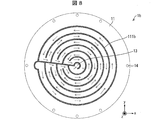
- FIG. 8 is a diagram illustrating an appearance of the heat exchanger 1b according to the third embodiment when viewed from the vertically upward side.
- FIG. 9 is a cross-sectional view of the heat exchanger 1b according to the third embodiment.
- Example 3 the shape of the inner rib 111b is substantially spiral, but unlike Examples 1 and 2, it is not a simple spiral. As shown in FIG. 8, in Example 3, the inner surface rib 111 b is lowered by one step before the first flow path makes one turn around the inner peripheral surface of the flow path forming portion 11, and when the first step is lowered, the inner rib 111 b makes one turn in the opposite direction. It is formed to repeat.
- the first flow path of the heat exchange liquid 110 is substantially horizontal at each stage.
- the first flow path is lowered to a lower position at a location where the flow direction of the heat exchange liquid 110 changes.
- the time required for heat exchange of the heat exchange liquid 110 becomes longer than in the first and second embodiments, and the heat exchange liquid 110 is contained in the heat exchanger 1b. Since it tends to remain, in addition to the purpose of use such as the amount and temperature of the heat exchange liquid 110 to be obtained, the configuration of the entire heat exchange system such as the capacity of the tank 2, the performance of the pump 3, the presence of the auxiliary cooling mechanism 6 or heater It is preferable to adopt the shape of the inner surface rib 111b of Example 3 after carefully examining the above.
- the height of the inner surface rib 111b may be increased on the lower side of the flow path forming portion 11.
- the shape of the outer rib 112 in the third embodiment is the same as that in the first embodiment. That is, the shape of the second flow path is the same as that of the first embodiment.
- the first flow path inside the flow path forming unit 11 is used as the flow path of the heat exchange liquid 110 (heat exchange liquid flow path), and the second flow path outside is used as the heat exchange liquid.
- the flow path of the replacement liquid 120 heat exchange liquid flow path
- the present invention is not limited to this, and the first flow path inside the flow path forming unit 11 is used as the flow path of the heat exchange liquid 120 (heat exchange).
- Liquid channel), and the outer second channel may be a channel of the heat exchange liquid 110 (heat exchange liquid channel).
- the second flow path is spiral, but the present invention is not limited to this.
- the second flow path may have the same shape as the first flow path shown in the third embodiment.
- the flow path forming portion 11 may not include the outer rib 112, and the second flow path may be a space between the flow path forming portion 11 and the flow path cover portion 12.
- the heat exchange liquid inlet 121 and the heat are placed at positions as shown in FIG.
- the heat exchange liquid inlet 121 is disposed below the flow path cover portion 12, and the heat exchange liquid outlet 122 is disposed above the flow path cover portion 12. This is because if the heat exchange liquid 120 is introduced from above, a flow path path is formed and heat exchange cannot be performed sufficiently.
- FIG. 11 is a perspective view of a cross section of the heat exchanger 1c according to the fourth embodiment.
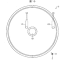
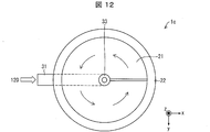
- FIG. 12 is a diagram illustrating an appearance of the heat exchanger 1c according to the fourth embodiment when viewed from the vertically upward side.
- the center axis of the cylinder is the Z axis
- the axes orthogonal to the center axis are the X axis and the Y axis.
- the heat exchanger 1 c includes a flow path forming part 21, a flow path cover part 22, a heat exchange liquid piping member 33, a heat exchange liquid inlet member 31, and a heat exchange liquid outlet member 32.
- the flow path forming part 21 forms the flow path (heat exchange liquid flow path) of the heat exchange liquid 110 together with the flow path cover part 22 and the heat exchange liquid piping member 33.
- the flow path forming portion 21 has a spiral shape extending from the heat exchange liquid piping member 33 in a direction substantially parallel to the XY plane.
- the flow path cover portion 22 has a hollow cylindrical shape, and the inner surface of the flow path cover portion 22 abuts against the radial end portion of the flow path forming portion 21.
- the heat exchange liquid piping member 33 forms a flow path of the heat exchange liquid 120, and is a pipe disposed on the central axis of the heat exchanger 1c. One end of the heat exchange liquid piping member 33 is connected to the heat exchange liquid inlet member 31, and the other end is connected to the heat exchange liquid outlet member 32.
- the heat exchange liquid piping member 33, the heat exchange liquid inlet member 31, and the heat exchange liquid outlet member 32 are each sealed by an O-ring 25.
- the heat exchange liquid inlet member 31 is disposed on the vertically downward side of the heat exchange liquid piping member 33
- the heat exchange liquid outlet member 32 is disposed on the vertically upward side of the heat exchange liquid piping member 33.
- the reverse is also possible.
- the heat exchanger 1c is provided with a spirally heated object having the heat exchange liquid piping member 33 as a central axis by the flow path forming portion 21, the flow path cover portion 22, and the heat exchange liquid piping member 33.
- a heat exchange liquid channel that is a channel for the exchange liquid is formed.
- the heat exchange liquid channel is a closed channel that is closed by the channel forming unit 21, the channel cover unit 22, and the heat exchange liquid piping member 33.
- the heat exchange liquid 110 is supplied from the vertically upward side of the heat exchanger 1c and poured into the uppermost heat exchange liquid flow path.
- the heat exchange liquid 110 poured into the uppermost heat exchange liquid flow path flows by its own weight vertically downward while rotating the spiral flow path formed by the flow path forming unit 21.
- the heat exchange liquid 110 exchanges heat with the heat exchange liquid 120 flowing through the heat exchange liquid piping member 33.
- the heat exchange liquid 110 is dripped at the cup 5 from the discharge port 23 of the heat exchanger 1c.
- the heat exchange liquid flow path through which the heat exchange liquid 110 flows is helical, the flow path length of the heat exchange liquid 110 becomes long. Therefore, the surface area used for heat exchange (the area where the heat exchange liquid 110 is in contact with the heat exchange liquid flow path) increases with respect to the volume of the heat exchange liquid 110, so that the efficiency of heat exchange is improved.
- the flow path cover part 22, the heat exchange liquid inlet member 31, and the heat exchange liquid outlet member 32 are detachable from the heat exchanger 1c. By removing the heat exchange liquid inlet member 31 and the heat exchange liquid outlet member 32 from the heat exchange liquid piping member 33, the flow path cover portion 22 can be removed. Further, the flow path forming part 21 and the heat exchange liquid piping member 33 may be integrated or separable. However, from the viewpoint of heat exchange efficiency, it is desirable that the flow path forming portion 21 and the heat exchange liquid piping member 33 are integrated.
- the heat exchange liquid flow channel in a state where the flow channel cover portion 22 is removed has a groove shape in which one side surface in a direction perpendicular to the direction in which the liquid flows through the flow channel is released.
- the heat exchanger according to the present invention can adjust the temperature of the heat exchange liquid (particularly, cooling the milk after milk preparation) in a sanitary and short time.
- the temperature can be adjusted to an appropriate temperature.
- the heat exchanger has a simple structure, it can be manufactured at low cost.
- it is possible to cool and warm sanitary beverages, and in particular, cool high-temperature milk after milk preparation to an appropriate temperature. For this reason, the troublesome operation
- the heat exchanger according to the first aspect of the present invention is a heat exchanger that adjusts the temperature of the heat exchange liquid by performing heat exchange between the heat exchange liquid and the heat exchange fluid,
- a flow path forming portion having a conical shape, and the flow path forming portion is a heat-receiving liquid flow channel formed in a substantially spiral shape on the inner peripheral surface of the flow path forming portion. It has an exchange liquid channel, and the above-mentioned heat exchange liquid channel is a channel in the shape of a groove whose upper part is opened vertically.
- the heat exchange liquid channel through which the heat exchange liquid flows is a groove-like channel in which a vertically upper portion is released, the washing of the heat exchange liquid channel and the above The state of the heat exchange liquid channel can be easily confirmed. Therefore, hygiene management of the heat exchange liquid channel can be easily performed. Therefore, the heat exchange liquid can be hygienically adjusted to a desired temperature.
- the heat exchanger according to aspect 2 of the present invention is the heat exchanger according to aspect 1, wherein the heat exchange liquid flow path includes a rib extending substantially vertically upward from an inner peripheral surface of the flow path forming part, and the flow path forming part. May be formed by the inner peripheral surface.
- the members constituting the heat exchanger can be manufactured by molding. Therefore, a heat exchanger can be manufactured at low cost.
- the height of the rib on the vertically lower side of the flow path forming portion is higher than the height of the rib on the vertical upper side of the flow path forming portion. It may be high.
- the heat exchange liquid supplied to the heat exchanger exceeds the amount that can be discharged from the discharge port of the heat exchanger, the heat exchange liquid is below the flow path forming part (heat exchange liquid flow path). It will be accumulated in. At this time, since the ratio of the surface area where heat exchange is performed with respect to the heat exchange liquid volume decreases, the efficiency of heat exchange decreases.
- the surface area (heat exchange) that allows heat exchange by increasing the height of the rib on the lower side of the flow path forming portion Since the area of the interface between the liquid and the ribs can be increased, it is possible to suppress a decrease in heat exchange efficiency.
- a heat exchanger is a heat exchanger that adjusts the temperature of the heat exchange liquid by performing heat exchange between the heat exchange liquid and the heat exchange fluid, A conical portion-shaped channel forming portion, a substantially funnel-shaped conical portion detachable channel cover portion, and a substantially spiral shape formed between the channel forming portion and the channel cover portion.
- a heat exchange liquid channel that is a channel of the heat exchange liquid, and the heat exchange liquid channel is freed from a radial side portion when the channel cover part is removed. It is a groove-shaped channel.
- the heat exchange liquid channel through which the heat exchange liquid flows is a groove-like channel in which a portion on the radial direction side is released when the channel cover portion is removed. It is possible to easily clean the heat exchange liquid channel and check the state of the heat exchange liquid channel. Therefore, hygiene management of the heat exchange liquid channel can be easily performed. Therefore, the heat exchange liquid can be hygienically adjusted to a desired temperature.
- a heat exchanger is a heat exchanger that adjusts the temperature of the heat exchange liquid by performing heat exchange between the heat exchange liquid and the heat exchange fluid, and is substantially hollow.
- a heat exchange liquid channel which is a channel of the heat exchange liquid, spirally formed between the channel formation unit, the channel formation unit, the channel cover unit, and the piping member.
- the heat exchange liquid channel is a groove-like channel in which a radial side portion is released when the channel cover part is removed.
- the heat exchange liquid channel through which the heat exchange liquid flows is a groove-like channel in which a portion on the radial direction side is released when the channel cover portion is removed. It is possible to easily clean the heat exchange liquid channel and check the state of the heat exchange liquid channel. Therefore, hygiene management of the heat exchange liquid channel can be easily performed. Therefore, the heat exchange liquid can be hygienically adjusted to a desired temperature.
- a heat exchange system includes a heat exchanger according to any one of aspects 1 to 5, a storage unit that stores the heat exchange fluid, and the heat exchange fluid from the storage unit to the heat exchanger.
- a supply unit for supplying to the exchanger.
- emitted from the said heat exchanger can be changed by increasing / decreasing the supply amount of the said heat exchange fluid which the said supply part supplies to the said heat exchanger. it can. For example, when cooling a high-temperature heat exchange liquid with a low-temperature heat exchange liquid, if the supply amount of the heat exchange liquid is increased, the temperature of the heat exchange liquid discharged from the heat exchanger is relatively When the supply amount is decreased, the temperature of the heat exchange liquid discharged from the heat exchanger can be relatively increased.
- the present invention it is possible to provide a heat exchanger that facilitates cleaning of the liquid flow path and confirmation of the state of the liquid flow path, and cooling and warming sanitary beverages, in particular, to an appropriate temperature of hot milk after milk preparation. Can be cooled.
- the heat exchanger according to the present invention can be manufactured by molding by adopting the shape as described above, and cutting and the like are almost unnecessary and the manufacturing cost is low. Therefore, it is widely used by many people who are raising children. It is possible.
- Heat exchanger 2 Tank storage part
- Pump supply section
- Heater 11 Heating
- 21 Flow path forming part 12
- Heat exchange liquid outlet member 23
- Heat exchange liquid piping member 110
- Internal rib (rib) 112
- External rib 120
- Heat exchange liquid 121
- Heat exchange liquid inlet 122 Heat exchange liquid outlet
Landscapes
- Engineering & Computer Science (AREA)
- Physics & Mathematics (AREA)
- Thermal Sciences (AREA)
- Mechanical Engineering (AREA)
- General Engineering & Computer Science (AREA)
- Food Science & Technology (AREA)
- Heat-Exchange Devices With Radiators And Conduit Assemblies (AREA)
- Medical Preparation Storing Or Oral Administration Devices (AREA)
Abstract
流体流路の洗浄および流体流路の状態確認を容易に行うことが可能な熱交換器および熱交換システムを実現する。被熱交換(110)と熱交換用流体(120)との間で熱交換を行って、被熱交換液体の温度を調整する熱交換器(1)であって、略漏斗の円錐部分の形状の流路形成部(11)を備え、流路形成部(11)は、流路形成部(11)の内周面上に略螺旋状に形成された、被熱交換液体(110)の流路である被熱交換液体流路を有し、被熱交換液体流路は、鉛直上方部分が解放されている溝状の流路である。
Description
本発明は流体間の熱の交換を行う熱交換器および熱交換システム、特に、飲料用の高温液体を低温流体により冷却する熱交換器および熱交換システムに関するものである。
近年、WHO(世界保健機関:World Health Organization)とFAO(国連食糧農業機関:Food and Agriculture Organization of the United Nations)が共同作成した「乳児用調整粉乳の安全な調乳、保存及び取扱いに関するガイドライン」によれば、乳児用の粉ミルクでは、エンテロバクター・サカザキなどへの感染による乳児の重篤な疾患や死亡との関連が報告されており、さらにこの対策としては、乳児に与える粉ミルク調乳用の飲料水は、70℃以上に沸かして使用しなければならない、とされている。このため、乳児に粉ミルクを調乳し、与えるためには、70℃程度で調乳したミルクを40℃程度にまで冷却する必要がある。
このような乳児用のミルクを高温から適温に冷却する方法としては、哺乳瓶内の高温のミルクを、水道水等を用いて外部から冷やすことが一般的である。
このことに関して、冷却を簡便化する手段として、例えば特許文献1に示すように、哺乳瓶冷却容器に哺乳瓶を揺動可能に保持する保持手段を設け、哺乳瓶冷却容器を揺動することにより哺乳瓶を揺動させ、これによって哺乳瓶内のミルクを攪拌するとともに、哺乳瓶の揺動により冷媒を攪拌するといった構成が明示されている。
一方、乳児用のミルクに限らず、一般的な液体の冷却については熱交換を用いる方法があり、例えば特許文献2には、沸騰温度近くまで加熱された水を、加熱前の水タンクの中を通る配管内に導かれることにより冷却されて湯冷ましが作れる装置が示されている。
また、特許文献3には、「黄金分割」に従った少なくとも1つの対数曲線にほぼ一致する彎曲を呈する作用面上に流体を流し、この作用面と、流体との間で熱交換を行う熱交換器が記載されている。
しかしながら、特許文献1に示す従来技術では、冷却容器を用いても5分以上の冷却時間が必要となっている。これは特許文献1に示すような、哺乳瓶等の容器に入っているミルク等の液体を冷却する方法では、冷媒と接触する面積が哺乳瓶等の容器の表面積に限られているためである。
さらに、この方法では予め冷却器を数時間冷蔵庫で冷やしておく必要がある等、利便性にも課題がある。特に生後間もない乳児に粉ミルクを調乳して与える場合では、数時間おきにミルクを与える必要があるうえ、夜間もミルクを与える必要があるため、冷却器を冷やすといった煩わしい作業は極力なくすことが望ましい。
また、特許文献2に示す従来技術では、液体が流れる配管を取外し、配管内を洗浄することが困難なうえ、配管内を目視で確認することも困難である。そのため、調乳後のミルクに限らず、コーヒーやお茶といった飲料を衛生的に保つことが困難である。
また、特許文献3に示す従来技術では、液体流路が複雑な形状であるため、流路の洗浄および流路の状態確認を容易に行うことができず、衛生管理が困難となる。
本発明は、上記の問題点に鑑みてなされたものであり、その目的は、流体流路の洗浄および流体流路の状態確認を容易に行うことが可能な熱交換器および熱交換システムを実現することにある。
上記の課題を解決するために、本発明の一態様に係る熱交換器は、被熱交換液体と熱交換用流体との間で熱交換を行って、被熱交換液体の温度を調整する熱交換器であって、略漏斗の円錐部分の形状の流路形成部を備え、上記流路形成部は、当該流路形成部の内周面上に略螺旋状に形成された、上記被熱交換液体の流路である被熱交換液体流路を有し、上記被熱交換液体流路は、鉛直上方部分が解放されている溝状の流路である。
本発明の一態様によれば、被熱交換液体を衛生的に所望の温度に調整することができるという効果を奏する。
本発明の一実施形態について図1から図12に基づいて説明すると以下の通りである。なお、以下では、70℃に調乳されたミルクを水によって、適温(40度程度)に冷却する熱交換器について説明する。ここで、上記のミルクのような、冷却される液体を被熱交換液体と称し、上記の水のような、被熱交換液体を冷却する液体を熱交換用液体(熱交換用流体)と称する。
ただし、被熱交換液体はミルクに限るものではなく、飲料用の液体など、任意の液体でよい。また、熱交換用液体も水に限るものではなく、任意の液体でもよい。さらに、熱交換用液体として液体ではなく任意の気体を用いてもよい。また、熱交換用液体として、飲用に適した水道水を用いることが好ましい。熱交換用液体は、被熱交換液体等の直接口に触れるものと接触することはないが、熱交換器の洗浄時などに、熱交換用液体の流路から被熱交換液体の流路へと雑菌等が移動する可能性があるため、熱交換用液体として衛生的に問題のないものを用いた方がよい。
また、以下では、被熱交換液体を熱交換用液体で冷却する熱交換器について説明するが、熱交換器は、熱交換用液体によって、被熱交換液体を加熱してもよい。
〔熱交換システムの構成〕
図1は、本発明の一実施形態に係る熱交換システムの構成の一例を示す図である。図1に示すように、熱交換システム100は、熱交換器1、タンク(貯蔵部)2およびポンプ(供給部)3を含む。
図1は、本発明の一実施形態に係る熱交換システムの構成の一例を示す図である。図1に示すように、熱交換システム100は、熱交換器1、タンク(貯蔵部)2およびポンプ(供給部)3を含む。
熱交換器1は、熱交換用液体と被熱交換液体との間で熱交換を行うものである。熱交換器1は、タンク2およびポンプ3とそれぞれ接続されている。タンク2は、熱交換用液体120を貯蔵するものである。ポンプ3は、タンク2に貯蔵されている熱交換用液体120を熱交換器1へ送り出すものである。
熱交換用液体120は、タンク2、ポンプ3および熱交換器1を循環する。具体的には、熱交換用液体120は、ポンプ3によってタンク2から熱交換器1に送られ、熱交換器1の中に配設されている流路内を通って被熱交換液体110と熱交換した後、タンク2に流入する。
熱交換器1の上部には被熱交換液体出口4が配置されており、被熱交換液体出口4から熱交換を受ける被熱交換液体110が熱交換器1に向かって注がれる。熱交換器1には、被熱交換液体110の流路が、上面が解放された形状で形成されており、上方から注がれる被熱交換液体110を受けることが可能となっている。被熱交換液体110は熱交換器1の流路内を上から下に自重で流れ落ち、この間に熱交換用液体120と熱交換が行われる。その後、被熱交換液体110は、熱交換器1から流出し、カップ5内に注がれる。被熱交換液体110が乳児用のミルクであれば、カップ5に代えて哺乳瓶を直接おいてもよい。
また、ポンプ3にて熱交換用液体120の送り流量を変化させることにより熱交換量を変えることができるため、熱交換器1から流出する被熱交換液体110の温度を変えることが可能となる。流量を増やすと被熱交換液体110の温度は熱交換用液体120の温度に近づく方向に変化し、流量を減らすと遠ざかる方向に変化する。より具体的には、低温の熱交換用液体120によって、高温の被熱交換液体110を冷却するため、熱交換用液体120の送り流量を増加させると、熱交換器1から流出する被熱交換液体110の温度は低下し、送り流量を減少させると、熱交換器1から流出する被熱交換液体110の温度は上昇する。
次に、熱交換システムの変形例について図2に基づいて説明する。図2は、別の熱交換システムの構成の一例を示す図である。図2に示す熱交換システム101は、図1に示す熱交換システム100と異なり、タンク2に補助冷却機構6が設置されている。補助冷却機構6は、ファンによる空冷機構、ペルチェ素子による冷却機構、または、フィンの設置による放熱機構等である。
熱交換用液体120によって被熱交換液体110を冷却する場合、熱交換用液体120は被熱交換液体110との熱交換によって温度が上昇していく。特に被熱交換液体110
の量(熱交換用液体120に対する相対的な量)が多かったり、被熱交換液体110の温度が非常に高いものであったりした場合、熱交換用液体120の温度上昇は大きくなってしまう。熱交換用液体120の温度が上昇してしまうと、被熱交換液体110との温度差が小さくなってしまうため、熱交換量が低下してしまう。
の量(熱交換用液体120に対する相対的な量)が多かったり、被熱交換液体110の温度が非常に高いものであったりした場合、熱交換用液体120の温度上昇は大きくなってしまう。熱交換用液体120の温度が上昇してしまうと、被熱交換液体110との温度差が小さくなってしまうため、熱交換量が低下してしまう。
そのため、補助冷却機構6によりタンク2に貯蔵されている熱交換用液体120を冷却することにより、熱交換器1における熱交換によって上昇した熱交換用液体120の温度を低下させることができる。それゆえ、熱交換用液体120の温度を低温で維持することができ、熱交換量の低下を抑制することができる。さらに、タンク2に貯蔵する冷却用水としての熱交換用液体120の量を少なくすることも可能となる。
次に、熱交換システムの他の変形例について図3に基づいて説明する。図3は、他の熱交換システムの構成の一例を示す図である。図3に示す熱交換システム102は、図1に示す熱交換システム100と異なり、タンク2にヒーター7が設置されている。図3に示す熱交換システム102は、高温の熱交換用液体120を用いて、低温の被熱交換液体110を温めるものである。
冷蔵庫等で保管され、冷えている飲料液体の加温方法としては電子レンジによる加熱が一般的である。しかしながら、電子レンジによる加熱は、不均一であり、局所的に熱いホットスポットができてしまうことが知られている。このようなホットスポットを避けたい利用シーン、例えば、調乳後ミルクの再加温する場合などに、熱交換システム102による加温が適している。
〔熱交換器の構成〕
次に、熱交換器1の構成について、図4および図5に基づいて説明する。熱交換器1は、流路形成部11および流路カバー部12を備える。図4は流路形成部11の外観を示す斜視図であり、図5は流路カバー部12の外観を示す斜視図である。
次に、熱交換器1の構成について、図4および図5に基づいて説明する。熱交換器1は、流路形成部11および流路カバー部12を備える。図4は流路形成部11の外観を示す斜視図であり、図5は流路カバー部12の外観を示す斜視図である。
図4および図5に示すように、流路形成部11および流路カバー部12は、漏斗の円錐部分とほぼ同じ形状である。換言すると、流路形成部11および流路カバー部12は、上面および底面が開口する略円錐台の形状である。ここで、円錐部分の中心軸をZ軸とし、円錐部分の中心軸と直交する軸をX軸、Y軸とする。
流路形成部11は、本体部分である円錐部115と、円錐部115の内周面に形成された内面リブ111と、円錐部の外周面に形成された外面リブ112とを含む。内面リブ111は、円錐部115の内周面から略鉛直上向き(Z軸の正方向)に伸長するものである。また、外面リブ112は、円錐部115の外周面からXY平面と略平行な方向に伸長するものである。
図5に示すように、流路カバー部12は、ポンプ3によって供給される熱交換用液体120の流入口である熱交換用液体入口121と、熱交換器1から排出される熱交換用液体120の流出口である熱交換用液体出口122とを備える。図5に示す例では、熱交換用液体入口121は流路カバー部12の下部に配置され、熱交換用液体出口122は流路カバー部12の上部に配置されている。ただし、これに限るものではなく、熱交換用液体入口121は流路カバー部12の上部に配置され、熱交換用液体出口122は流路カバー部12の下部に配置されてもよい。
熱交換器1は、流路カバー部12の内周面側に、流路形成部11を収容させて、流路形成部11と流路カバー部12を係合させたものである。流路形成部11の下部開口部113と流路カバー部12の下部開口部123とにより、熱交換器1の被熱交換液体110の排出口が形成される。流路形成部11に設けられた締結用貫通穴114と、流路カバー部12に設けられた締結用貫通穴124とに留め具を通して流路形成部11と流路カバー部12とが固定される。なお、流路形成部11と流路カバー部12とを挟む固定治具を用いて両者を固定してもよい。
ここで、被熱交換液体110の流路である第1流路は、流路形成部11の円錐部115の内周面と内面リブ111とによって形成される。第1流路は鉛直上方部分が解放されている溝状の形状である。また、熱交換用液体120の流路である第2流路は、流路形成部11の円錐部115の外周面と、外面リブ112と、流路カバー部12の内周面とによって形成される。第2流路は、円錐部115の外周面と、外面リブ112と、流路カバー部12の内周面とによって閉じられた空間(閉流路)である。このように、流路形成部11および流路カバー部12は型成型時に面倒となるアンダーカット等が無く、抜き勾配も付けやすい簡単な形状であるため、熱交換器1を構成する流路形成部11および流路カバー部12を型成型によって容易に作製することができるため、製造コストを低減することができる。
次に、内面リブ111および外面リブ112の形状、並びに、第1流路および第2流路の形状について3つの実施例1~3を例示して説明する。
(実施例1)
まず、図6に基づいて、実施例1に係る熱交換器1を説明する。図6は、実施例1に係る熱交換器1の断面図である。
まず、図6に基づいて、実施例1に係る熱交換器1を説明する。図6は、実施例1に係る熱交換器1の断面図である。
図6に示すように、内面リブ111は、流路形成部11の円錐部115の内周面の上部辺縁から下部中央にまで、螺旋状に形成されている。すなわち、実施例1における第1流路は、螺旋状の形状である。また、外面リブ112は、流路形成部11の円錐部115の外周面の上部辺縁から下部中央にまで、螺旋状に形成されている。すなわち、実施例1における第2流路は、螺旋状の形状である。換言すると、第1流路は、流路形成部11の内周面に沿って形成された、円錐部分の中心軸を中心軸とする螺旋状の形状である。一方、第2流路は、流路形成部11の外周面に沿って形成された、円錐部分の中心軸を中心軸とする螺旋状の形状である。
図6に示すように、流路形成部11の外面リブ112の端部と流路カバー部12の内表面とが当接している。流路形成部11と流路カバー部12は、2つのOリング15によってシールされ、留め具14によって固定される。
被熱交換液体110は、熱交換器1の鉛直上向き側から供給され、上段(望ましくは最上段)の第1流路に注がれる。上段の第1流路に注がれた被熱交換液体110は、内面リブ111によって形成された螺旋状流路を回転しながら鉛直下向きに自重で流れる。第1流路を流れる間に、被熱交換液体110は、流路形成部11の外側を流れる熱交換用液体120と熱交換を行う。そして、被熱交換液体110は、熱交換器1の排出口13からカップ5へ滴下される。
このように、被熱交換液体110が流れる第1流路が螺旋状であることにより、被熱交換液体110の流路長は長くなる。そのため、熱交換に利用される表面積(被熱交換液体110が第1流路と接触する面積)が被熱交換液体110の体積に対して大きくなるため、熱交換の効率が向上する。
ここで、内面リブ111の高さは熱交換器1(流路形成部11の円錐部115)の上端面(鉛直上向き側の端面)を超えないようにしておくことが望ましい。内面リブ111の高さを熱交換器1の上端面を超えないようにしておくことで、万が一、被熱交換液体110の量が熱交換器1(第1流路)から溢れるほど多く注がれたとしても、内面リブ111から熱交換器1の中心軸方向に被熱交換液体110が溢れる。そのため、第1流路から溢れた被熱交換液体110は排出口13より出ることになり、下方にあるカップ5で受けられるからである。
逆に内面リブ111の高さが熱交換器1の上端面よりも高い場合は、熱交換器1の外周方向(半径方向)に被熱交換液体110が溢れるため、カップ5の外に漏れていく恐れがある。さらに、内面リブ111の高さが高くなると、熱交換器1の取り扱い時に、内面リブ111を折ってしまう危険性が非常に高くなるため、好ましくない。
一方、タンク2からポンプ3によって送られてくる熱交換用液体120は、熱交換器1の下部の熱交換用液体入口121から供給される。熱交換用液体120は、流路形成部11と流路カバー部12との間に形成された螺旋状の第2流路内を回転しながら鉛直上向きに流れていき、熱交換用液体出口122から排出される。熱交換用液体120は、第2流路を流れている間に、流路形成部11の内側を流れる被熱交換液体110と熱交換を行う。
熱交換用液体入口121および熱交換用液体出口122に、差し込み口のある固定台を別途設けておくことにより、熱交換器1と熱交換用液体を通る配管との抜き差しが簡便になる。また、熱交換用液体入口121および熱交換用液体出口122において、シリコーンチューブなどの配管をホースバンド等にて固定してもよい。
このように、漏斗の円錐部分の形状である流路形成部11の内表面から鉛直上向きに伸長する内面リブ111によって第1流路が形成される。この第1流路は鉛直上方部分が解放されている溝状の形状であることにより、被熱交換液体110が流れる第1流路の洗浄、および、第1流路の状態(特に衛生的な状態)の確認を容易に行うことができる。さらに、第1流路は鉛直上方部分が解放されているため、第1流路内を目視することができ、表面の汚れ等の有無を容易に確認することができる。したがって、被熱交換液体110が流れる流路の衛生管理が容易である。
また、流路形成部11と流路カバー部12とは容易に脱着可能である。流路カバー部12を取り外すと、外面リブ112によって形成される第2流路は、半径方向側の部分が解放されている。そのため、流路カバー部12を取り外すことにより、熱交換用液体120が流れる第2流路の洗浄、および、第2流路の状態確認を容易に行うことができる。また、流路カバー部12を取り外すことにより、第2流路内を目視することができる。
なお、換言すると、第1流路および流路カバー部12が取り外された状態における第2流路は、流路を液体が自重で流れる方向と直交する方向の一側面が解放された溝形状である。
(実施例2)
次に、図7に基づいて、実施例2に係る熱交換器1aを説明する。図7は、実施例2に係る熱交換器1aの断面図である。
次に、図7に基づいて、実施例2に係る熱交換器1aを説明する。図7は、実施例2に係る熱交換器1aの断面図である。
図7に示すように、内面リブ111aは、実施例1と同様に、流路形成部11の円錐部115の内周面の上部辺縁から下部中央にまで、螺旋状に形成されている。ただし、実施例2では、流路形成部11の上部側(鉛直上方側)の内面リブ111aの高さより、流路形成部11の下部側(鉛直下方側)の内面リブ111aの高さを高くする。例えば、内面リブ111aの高さが、流路形成部11の下方(鉛直下向き)にいくにしたがって、高くなっていてもよい。
熱交換器1に供給される被熱交換液体110の量が、排出口13から排出可能な量を超えた場合、被熱交換液体110が熱交換器1の下部に溜っていくことになる。この時、被熱交換液体110の体積に対して熱交換がおこなわれる表面積の割合が低下してしまうため、熱交換の効率が低下する。
この場合においても、熱交換器1の下方側で内面リブ111aの高さを高くしておくことにより、熱交換ができる表面積(被熱交換液体110と内面リブ111aとの界面の面積)を多くとることができるため、熱交換効率の低下を抑制することができる。
一方で、内面リブ111aの高さを高くしすぎると、内面リブ111aが折れやすくなってしまう他、洗い難くなってしまうため、被熱交換液体110の投入量との兼ね合いを考慮して内面リブ111aの高さを設計することが好ましい。
なお、実施例2における外面リブ112の形状は実施例1と同じである。すなわち、第2流路の形状も実施例1と同じである。
(実施例3)
次に、図8および図9に基づいて、実施例3に係る熱交換器1bを説明する。図8は、実施例3に係る熱交換器1bの鉛直上向き側から見た外観を示す図である。図9は、実施例3に係る熱交換器1bの断面図である。
次に、図8および図9に基づいて、実施例3に係る熱交換器1bを説明する。図8は、実施例3に係る熱交換器1bの鉛直上向き側から見た外観を示す図である。図9は、実施例3に係る熱交換器1bの断面図である。
実施例3では、内面リブ111bの形状は、略螺旋状であるが、実施例1および2と異なり、単純な螺旋状ではない。図8に示すように、実施例3では、内面リブ111bは、第1流路が流路形成部11の内周面を1周する手前で1段下がり、1段下がると反対方向に1周することを繰り返すように形成されている。
また、図9の熱交換器1bの断面図に示されるように、被熱交換液体110の流れる方向は、段を下るごとに図に向かって左側、右側と交互に向きが変わっているほか、被熱交換液体110の第1流路は各段で略水平となっている。また、第1流路は被熱交換液体110の流れる向きが変わる箇所で下段に下がる。
このため、被熱交換液体110の流れが方向転換の際に一旦止められるうえ、流路形成部11の内周面を旋回している際には自重で流れが加速されないようになっている。
これによって、被熱交換液体110が熱交換器1b(第1流路)に滞在する時間は長くなるため、熱交換量を大きくさせることが可能となる。
一方で本実施例の内面リブ111b形状では、実施例1および実施例2より被熱交換液体110の熱交換にかかる時間が長くなってしまうほか、熱交換器1b内に被熱交換液体110が残りやすくなってしまうため、得たい被熱交換液体110の量や温度といった使用目的のほか、タンク2の容量、ポンプ3の性能、補助冷却機構6またはヒーター7の有無といった熱交換システム全体の構成をよく吟味したうえで、実施例3の内面リブ111b形状を採用することが好ましい。
なお、実施例2と同様に、内面リブ111bの高さを流路形成部11の下部側が高くなるようにしてもよい。
また、実施例3における外面リブ112の形状は実施例1と同じである。すなわち、第2流路の形状も実施例1と同じである。
(実施例1~3の変形例)
なお、上述の実施例1~3では、流路形成部11の内側の第1流路を被熱交換液体110の流路(被熱交換液体流路)とし、外側の第2流路を熱交換用液体120の流路(熱交換用液体流路)としているが、これに限るものではなく、流路形成部11の内側の第1流路を熱交換用液体120の流路(熱交換用液体流路)とし、外側の第2流路を被熱交換液体110の流路(被熱交換液体流路)としてもよい。
なお、上述の実施例1~3では、流路形成部11の内側の第1流路を被熱交換液体110の流路(被熱交換液体流路)とし、外側の第2流路を熱交換用液体120の流路(熱交換用液体流路)としているが、これに限るものではなく、流路形成部11の内側の第1流路を熱交換用液体120の流路(熱交換用液体流路)とし、外側の第2流路を被熱交換液体110の流路(被熱交換液体流路)としてもよい。
また、上述の実施例1~3では、第2流路が螺旋状であるが、これに限るものではない。例えば、第2流路が、実施例3に示す第1流路と同様の形状であってもよい。
さらに、上述の実施例1~3において、流路形成部11が外面リブ112を備えず、第2流路が流路形成部11と流路カバー部12との間の空間であってもよい。この場合、流路形成部11と流路カバー部12との間の空間全体に熱交換用液体120が流れるようにするために、図10に示すような位置に熱交換用液体入口121および熱交換用液体出口122に配置し、さらに、熱交換用液体入口121は流路カバー部12の下方に配置し、熱交換用液体出口122は流路カバー部12の上方に配置することが好ましい。上方より熱交換用液体120を入れてしまうと流路パスができてしまい、熱交換が十分にできなくなってしまうためである。
(実施例4)
次に、実施例4として、円筒形の熱交換器について図11および図12に基づいて説明する。図11は、実施例4に係る熱交換器1cの断面の斜視図である。図12は、実施例4に係る熱交換器1cの鉛直上向き側から見た外観を示す図である。ここでは、円筒の中心軸をZ軸とし、中心軸と直交する軸をX軸、Y軸とする。
次に、実施例4として、円筒形の熱交換器について図11および図12に基づいて説明する。図11は、実施例4に係る熱交換器1cの断面の斜視図である。図12は、実施例4に係る熱交換器1cの鉛直上向き側から見た外観を示す図である。ここでは、円筒の中心軸をZ軸とし、中心軸と直交する軸をX軸、Y軸とする。
図11に示すように、熱交換器1cは、流路形成部21、流路カバー部22、熱交換用液体配管部材33、熱交換用液体入口部材31および熱交換用液体出口部材32を備える。流路形成部21は、流路カバー部22および熱交換用液体配管部材33と共に、被熱交換液体110の流路(被熱交換液体流路)を形成するものである。流路形成部21は、図11に示すように、熱交換用液体配管部材33からXY平面と略平行な方向に伸長する螺旋状の形状である。流路カバー部22は、中空の円筒形であり、流路カバー部22の内表面と流路形成部21の半径方向の端部とが当接する。熱交換用液体配管部材33は、熱交換用液体120の流路を形成するものであり、熱交換器1cの中心軸に配置された管である。熱交換用液体配管部材33は、その一端が熱交換用液体入口部材31と接続し、他端が熱交換用液体出口部材32と接続する。熱交換用液体配管部材33と熱交換用液体入口部材31および熱交換用液体出口部材32とは、それぞれOリング25によってシールされている。図示の例では、熱交換用液体入口部材31が熱交換用液体配管部材33の鉛直下向き側に配置され、熱交換用液体出口部材32が熱交換用液体配管部材33の鉛直上向き側に配置されているが、逆であってもよい。
上述のように、熱交換器1cには、流路形成部21、流路カバー部22および熱交換用液体配管部材33によって、熱交換用液体配管部材33を中心軸とする螺旋状の被熱交換液体の流路である被熱交換液体流路が形成されている。また、被熱交換液体流路は、流路形成部21、流路カバー部22および熱交換用液体配管部材33によって閉じられた閉流路である。
被熱交換液体110は、熱交換器1cの鉛直上向き側から供給され、最上段の被熱交換液体流路に注がれる。最上段の被熱交換液体流路に注がれた被熱交換液体110は、流路形成部21によって形成された螺旋状流路を回転しながら鉛直下向きに自重で流れる。被熱交換液体流路を流れる間に、被熱交換液体110は、熱交換用液体配管部材33を流れる熱交換用液体120と熱交換を行う。そして、被熱交換液体110は、熱交換器1cの排出口23からカップ5へ滴下される。
このように、被熱交換液体110が流れる被熱交換液体流路が螺旋状であることにより、被熱交換液体110の流路長は長くなる。そのため、熱交換に利用される表面積(被熱交換液体110が被熱交換液体流路と接触する面積)が被熱交換液体110の体積に対して大きくなるため、熱交換の効率が向上する。
流路カバー部22、熱交換用液体入口部材31および熱交換用液体出口部材32は、熱交換器1cから脱着可能である。熱交換用液体入口部材31および熱交換用液体出口部材32を熱交換用液体配管部材33から取り外すことにより、流路カバー部22を取り外すことが可能となる。また、流路形成部21と熱交換用液体配管部材33とは、一体であっても、分離可能であってもよい。ただし、熱交換効率の観点から、流路形成部21および熱交換用液体配管部材33は一体であることが望ましい。
流路カバー部22を取り外すと、流路形成部21によって形成される被熱交換液体流路は、半径方向側の部分が解放されている。そのため、流路カバー部22を取り外すことにより。被熱交換液体流路の洗浄、および、被熱交換液体流路の状態確認を容易に行うことができる。また、流路カバー部22を取り外すことにより、被熱交換液体流路内を目視することができる。
なお、換言すると、流路カバー部22が取り外された状態における被熱交換液体流路は、流路を液体が自重で流れる方向と直交する方向の一側面が解放された溝形状である。
まとめると、本発明に係る熱交換器(実施例1~4に係る熱交換器)は、被熱交換液体の温度調整(特に調乳後のミルクの冷却)を、衛生的にかつ、短時間で適当な温度まで調整することができる。さらに、熱交換器が単純な構造であるため、安価に製造することもできる。また、本発明により、衛生的な飲料の冷却および加温、特に、調乳後の高温ミルクの適温への冷却が可能となる。このため、調乳後に必要であった哺乳瓶を水道水等で冷却する煩わしい作業が不要となり、育児に対しての苦労を軽減することが可能となる。
〔まとめ〕
本発明の態様1に係る熱交換器は、被熱交換液体と熱交換用流体との間で熱交換を行って、被熱交換液体の温度を調整する熱交換器であって、略漏斗の円錐部分の形状の流路形成部を備え、上記流路形成部は、当該流路形成部の内周面上に略螺旋状に形成された、上記被熱交換液体の流路である被熱交換液体流路を有し、上記被熱交換液体流路は、鉛直上方部分が解放されている溝状の流路である。
本発明の態様1に係る熱交換器は、被熱交換液体と熱交換用流体との間で熱交換を行って、被熱交換液体の温度を調整する熱交換器であって、略漏斗の円錐部分の形状の流路形成部を備え、上記流路形成部は、当該流路形成部の内周面上に略螺旋状に形成された、上記被熱交換液体の流路である被熱交換液体流路を有し、上記被熱交換液体流路は、鉛直上方部分が解放されている溝状の流路である。
上記の構成によれば、上記被熱交換液体が流れる被熱交換液体流路は、鉛直上方部分が解放されている溝状の流路であるため、上記被熱交換液体流路の洗浄および上記被熱交換液体流路の状態確認を容易に行うことができる。よって、上記被熱交換液体流路の衛生管理を容易に行うことができる。したがって、被熱交換液体を衛生的に所望の温度に調整することができる。
本発明の態様2に係る熱交換器は、上記態様1において、上記被熱交換液体流路は、上記流路形成部の内周面から略鉛直上向きに伸長するリブと、上記流路形成部の内周面とによって形成されてもよい。
上記の構成によれば、単純な構造で流路を形成することができるため、熱交換器を構成する部材を型成型により作製することができる。よって、熱交換器を安価に製造することができる。
本発明の態様3に係る熱交換器は、上記態様2において、上記流路形成部の鉛直下方側の上記リブの高さは、上記流路形成部の鉛直上方側の上記リブの高さより、高くてもよい。
熱交換器に供給される被熱交換液体の量が、熱交換器の排出口から排出可能な量を超えた場合、被熱交換液体が流路形成部(被熱交換液体流路)の下部に溜っていくことになる。この時、被熱交換液体体積に対して熱交換がおこなわれる表面積の割合が低下してしまうため、熱交換の効率が低下する。
上記の構成によれば、被熱交換液体の供給量が多くなったとしても、流路形成部の下方側でリブの高さを高くしておくことにより、熱交換ができる表面積(被熱交換液体とリブとの界面の面積)を多くとることができるため、熱交換効率の低下を抑制することができる。
本発明の態様4に係る熱交換器は、被熱交換液体と熱交換用流体との間で熱交換を行って、被熱交換液体の温度を調整する熱交換器であって、略漏斗の円錐部分の形状の流路形成部と、略漏斗の円錐部分の形状の脱着可能な流路カバー部と、上記流路形成部と上記流路カバー部との間に略螺旋状に形成された、上記被熱交換液体の流路である被熱交換液体流路と、を備え、上記被熱交換液体流路は、上記流路カバー部を取り外すと、半径方向側の部分が解放されている溝状の流路である。
上記の構成によれば、上記被熱交換液体が流れる被熱交換液体流路は、上記流路カバー部を取り外すと、半径方向側の部分が解放されている溝状の流路であるため、上記被熱交換液体流路の洗浄および上記被熱交換液体流路の状態確認を容易に行うことができる。よって、上記被熱交換液体流路の衛生管理を容易に行うことができる。したがって、被熱交換液体を衛生的に所望の温度に調整することができる。
本発明の態様5に係る熱交換器は、被熱交換液体と熱交換用流体との間で熱交換を行って、被熱交換液体の温度を調整する熱交換器であって、中空の略円筒形の脱着可能な流路カバー部と、上記流路カバー部の中心軸に配置された、上記熱交換用流体が流れる配管部材と、上記配管部材から略半径方向に伸長する螺旋状の流路形成部と、上記流路形成部と上記流路カバー部と上記配管部材との間に螺旋状に形成された、上記被熱交換液体の流路である被熱交換液体流路と、を備え、上記被熱交換液体流路は、上記流路カバー部を取り外すと、半径方向側の部分が解放されている溝状の流路である。
上記の構成によれば、上記被熱交換液体が流れる被熱交換液体流路は、上記流路カバー部を取り外すと、半径方向側の部分が解放されている溝状の流路であるため、上記被熱交換液体流路の洗浄および上記被熱交換液体流路の状態確認を容易に行うことができる。よって、上記被熱交換液体流路の衛生管理を容易に行うことができる。したがって、被熱交換液体を衛生的に所望の温度に調整することができる。
本発明の態様6に係る熱交換システムは、上記態様1~5の何れかの熱交換器と、上記熱交換用流体を貯蔵する貯蔵部と、上記熱交換用流体を上記貯蔵部から上記熱交換器に供給する供給部と、を備える。
上記の構成によれば、上記供給部が上記熱交換器に供給する上記熱交換用流体の供給量を増減させることにより、上記熱交換器から排出される被熱交換液体の温度を変えることができる。例えば、低温の熱交換用液体によって、高温の被熱交換液体を冷却する場合、熱交換用液体の供給量を増加させると、熱交換器から排出される被熱交換液体の温度は相対的に低下させることができ、供給量を減少させると、熱交換器から排出される被熱交換液体の温度を相対的に上昇させることができる。
本発明は上述した実施形態に限定されるものではなく、請求項に示した範囲で種々の変更が可能である。すなわち、請求項に示した範囲で適宜変更した技術的手段を組み合わせて得られる実施形態についても本発明の技術的範囲に含まれる。
本発明により、液体流路の洗浄および液体流路の状態確認が容易な熱交換器を提供することができ、衛生的な飲料の冷却および加温、特に、調乳後の高温ミルクの適温への冷却が可能となる。また、本発明における熱交換器は上述のような形状とすることにより型成型による作製が可能で切削加工等はほとんど不要で製造コストは安価であるため、育児に携わる多くの人たちに普及させることが可能である。
1、1a、1b、1c、1d 熱交換器
2 タンク(貯蔵部)
3 ポンプ(供給部)
6 補助冷却機構
7 ヒーター
11、21 流路形成部
12、22 流路カバー部
13、23 排出口
31 熱交換用液体入口部材
32 熱交換用液体出口部材
33 熱交換用液体配管部材
110 被熱交換液体
111、111a、111b 内面リブ(リブ)
112 外面リブ
120 熱交換用液体
121 熱交換用液体入口
122 熱交換用液体出口
2 タンク(貯蔵部)
3 ポンプ(供給部)
6 補助冷却機構
7 ヒーター
11、21 流路形成部
12、22 流路カバー部
13、23 排出口
31 熱交換用液体入口部材
32 熱交換用液体出口部材
33 熱交換用液体配管部材
110 被熱交換液体
111、111a、111b 内面リブ(リブ)
112 外面リブ
120 熱交換用液体
121 熱交換用液体入口
122 熱交換用液体出口
Claims (5)
- 被熱交換液体と熱交換用流体との間で熱交換を行って、被熱交換液体の温度を調整する熱交換器であって、
略漏斗の円錐部分の形状の流路形成部を備え、
上記流路形成部は、当該流路形成部の内周面上に略螺旋状に形成された、上記被熱交換液体の流路である被熱交換液体流路を有し、
上記被熱交換液体流路は、鉛直上方部分が解放されている溝状の流路であることを特徴とする熱交換器。 - 上記被熱交換液体流路は、上記流路形成部の内周面から略鉛直上向きに伸長するリブと、上記流路形成部の内周面とによって形成されることを特徴とする請求項1に記載の熱交換器。
- 上記流路形成部の鉛直下方側の上記リブの高さは、上記流路形成部の鉛直上方側の上記リブの高さより、高いことを特徴とする請求項2に記載の熱交換器。
- 被熱交換液体と熱交換用流体との間で熱交換を行って、被熱交換液体の温度を調整する熱交換器であって、
略漏斗の円錐部分の形状の流路形成部と、
略漏斗の円錐部分の形状の脱着可能な流路カバー部と、
上記流路形成部と上記流路カバー部との間に略螺旋状に形成された、上記被熱交換液体の流路である被熱交換液体流路と、を備え、
上記被熱交換液体流路は、上記流路カバー部を取り外すと、半径方向側の部分が解放されている溝状の流路であることを特徴とする熱交換器。 - 請求項1~4の何れか1項に記載の熱交換器と、
上記熱交換用流体を貯蔵する貯蔵部と、
上記熱交換用流体を上記貯蔵部から上記熱交換器に供給する供給部と、を備える熱交換システム。
Applications Claiming Priority (2)
| Application Number | Priority Date | Filing Date | Title |
|---|---|---|---|
| JP2013-157641 | 2013-07-30 | ||
| JP2013157641A JP2015028396A (ja) | 2013-07-30 | 2013-07-30 | 熱交換器および熱交換システム |
Publications (1)
| Publication Number | Publication Date |
|---|---|
| WO2015015933A1 true WO2015015933A1 (ja) | 2015-02-05 |
Family
ID=52431475
Family Applications (1)
| Application Number | Title | Priority Date | Filing Date |
|---|---|---|---|
| PCT/JP2014/066111 Ceased WO2015015933A1 (ja) | 2013-07-30 | 2014-06-18 | 熱交換器および熱交換システム |
Country Status (2)
| Country | Link |
|---|---|
| JP (1) | JP2015028396A (ja) |
| WO (1) | WO2015015933A1 (ja) |
Cited By (3)
| Publication number | Priority date | Publication date | Assignee | Title |
|---|---|---|---|---|
| WO2018189887A1 (ja) * | 2017-04-14 | 2018-10-18 | 一男 中野 | 流下液膜式熱交換装置 |
| US10697708B2 (en) * | 2016-04-18 | 2020-06-30 | Hamilton Sunstrand Corporation | Heat exchangers |
| CN118463687A (zh) * | 2024-06-04 | 2024-08-09 | 江苏瑞鼎环境工程有限公司 | 一种焚烧炉低温段烟气余热的储冷系统及其工艺 |
Citations (4)
| Publication number | Priority date | Publication date | Assignee | Title |
|---|---|---|---|---|
| JPS57500706A (ja) * | 1980-05-27 | 1982-04-22 | ||
| JPH0677839U (ja) * | 1993-04-07 | 1994-11-01 | 森永乳業株式会社 | 分離機能を有する粉体熱交換器 |
| JPH1118944A (ja) * | 1997-07-02 | 1999-01-26 | Orion Mach Co Ltd | 調理装置 |
| JP2005513410A (ja) * | 2002-01-03 | 2005-05-12 | パックス サイエンティフィック インコーポレイテッド | 熱交換器 |
-
2013
- 2013-07-30 JP JP2013157641A patent/JP2015028396A/ja active Pending
-
2014
- 2014-06-18 WO PCT/JP2014/066111 patent/WO2015015933A1/ja not_active Ceased
Patent Citations (4)
| Publication number | Priority date | Publication date | Assignee | Title |
|---|---|---|---|---|
| JPS57500706A (ja) * | 1980-05-27 | 1982-04-22 | ||
| JPH0677839U (ja) * | 1993-04-07 | 1994-11-01 | 森永乳業株式会社 | 分離機能を有する粉体熱交換器 |
| JPH1118944A (ja) * | 1997-07-02 | 1999-01-26 | Orion Mach Co Ltd | 調理装置 |
| JP2005513410A (ja) * | 2002-01-03 | 2005-05-12 | パックス サイエンティフィック インコーポレイテッド | 熱交換器 |
Cited By (3)
| Publication number | Priority date | Publication date | Assignee | Title |
|---|---|---|---|---|
| US10697708B2 (en) * | 2016-04-18 | 2020-06-30 | Hamilton Sunstrand Corporation | Heat exchangers |
| WO2018189887A1 (ja) * | 2017-04-14 | 2018-10-18 | 一男 中野 | 流下液膜式熱交換装置 |
| CN118463687A (zh) * | 2024-06-04 | 2024-08-09 | 江苏瑞鼎环境工程有限公司 | 一种焚烧炉低温段烟气余热的储冷系统及其工艺 |
Also Published As
| Publication number | Publication date |
|---|---|
| JP2015028396A (ja) | 2015-02-12 |
Similar Documents
| Publication | Publication Date | Title |
|---|---|---|
| JP5476096B2 (ja) | 給水装置及びこれに用いられる水の冷却及び浄水方法 | |
| CN105996768B (zh) | 冷饮冲调装置、应用该装置的冲调机及饮用水的制备方法 | |
| CN102822610B (zh) | 冷水箱 | |
| WO2020048142A1 (zh) | 咖啡机及其控制方法 | |
| JP6611789B2 (ja) | 熱交換器、該熱交換器を備える冷却システム、該熱交換器の蒸発器としての使用、及び流体を冷却する方法 | |
| WO2015015933A1 (ja) | 熱交換器および熱交換システム | |
| WO2015059957A1 (ja) | 熱交換器および熱交換システム | |
| KR20180045757A (ko) | 언더 싱크형 먹는물 공급장치 | |
| JP2010083582A (ja) | 飲料サーバー | |
| JP2010247838A (ja) | 飲料水供給装置 | |
| JP6014882B2 (ja) | クリーンウォーター排出装置 | |
| CN109665641A (zh) | 一种净水饮水机 | |
| CN109422312B (zh) | 净水器 | |
| JP2011178408A (ja) | 飲料水供給装置 | |
| TW201102028A (en) | A beverage device with a container | |
| JP2015093680A (ja) | 飲料水ディスペンサ | |
| JP5809742B1 (ja) | ウォーターサーバー | |
| CN209769920U (zh) | 一种能使部分热水快速降温的保温杯 | |
| CN208843752U (zh) | 净水器的冷水供给系统 | |
| CN202234807U (zh) | 一种开水制冷饮水机 | |
| CN205597754U (zh) | 一种胶囊饮品的冲泡装置 | |
| JP2017023602A (ja) | 調乳装置 | |
| CN205018852U (zh) | 饮水机 | |
| ES2392909T3 (es) | Equipo para la preparación de alimentos | |
| CN208238603U (zh) | 一种两段式冷凝器 |
Legal Events
| Date | Code | Title | Description |
|---|---|---|---|
| 121 | Ep: the epo has been informed by wipo that ep was designated in this application |
Ref document number: 14832471 Country of ref document: EP Kind code of ref document: A1 |
|
| NENP | Non-entry into the national phase |
Ref country code: DE |
|
| 122 | Ep: pct application non-entry in european phase |
Ref document number: 14832471 Country of ref document: EP Kind code of ref document: A1 |