WO2015015822A1 - 製氷装置付冷蔵庫 - Google Patents
製氷装置付冷蔵庫 Download PDFInfo
- Publication number
- WO2015015822A1 WO2015015822A1 PCT/JP2014/054281 JP2014054281W WO2015015822A1 WO 2015015822 A1 WO2015015822 A1 WO 2015015822A1 JP 2014054281 W JP2014054281 W JP 2014054281W WO 2015015822 A1 WO2015015822 A1 WO 2015015822A1
- Authority
- WO
- WIPO (PCT)
- Prior art keywords
- ice
- ice tray
- drive shaft
- tray
- ice making
- Prior art date
- Legal status (The legal status is an assumption and is not a legal conclusion. Google has not performed a legal analysis and makes no representation as to the accuracy of the status listed.)
- Ceased
Links
Images


Classifications
-
- F—MECHANICAL ENGINEERING; LIGHTING; HEATING; WEAPONS; BLASTING
- F25—REFRIGERATION OR COOLING; COMBINED HEATING AND REFRIGERATION SYSTEMS; HEAT PUMP SYSTEMS; MANUFACTURE OR STORAGE OF ICE; LIQUEFACTION SOLIDIFICATION OF GASES
- F25C—PRODUCING, WORKING OR HANDLING ICE
- F25C1/00—Producing ice
- F25C1/22—Construction of moulds; Filling devices for moulds
- F25C1/24—Construction of moulds; Filling devices for moulds for refrigerators, e.g. freezing trays
-
- F—MECHANICAL ENGINEERING; LIGHTING; HEATING; WEAPONS; BLASTING
- F25—REFRIGERATION OR COOLING; COMBINED HEATING AND REFRIGERATION SYSTEMS; HEAT PUMP SYSTEMS; MANUFACTURE OR STORAGE OF ICE; LIQUEFACTION SOLIDIFICATION OF GASES
- F25C—PRODUCING, WORKING OR HANDLING ICE
- F25C2400/00—Auxiliary features or devices for producing, working or handling ice
- F25C2400/08—Auxiliary features or devices for producing, working or handling ice for different type of ice
-
- F—MECHANICAL ENGINEERING; LIGHTING; HEATING; WEAPONS; BLASTING
- F25—REFRIGERATION OR COOLING; COMBINED HEATING AND REFRIGERATION SYSTEMS; HEAT PUMP SYSTEMS; MANUFACTURE OR STORAGE OF ICE; LIQUEFACTION SOLIDIFICATION OF GASES
- F25C—PRODUCING, WORKING OR HANDLING ICE
- F25C2500/00—Problems to be solved
- F25C2500/02—Geometry problems
Definitions
- the present invention relates to a refrigerator with an ice making device in which an ice making device is installed in an ice making room.
- an ice making chamber of a refrigerator is provided with an ice making tray having a plurality of ice making recesses for storing water to make ice, and the plurality of ice making recesses are formed in the same shape so as to make ice of the same shape. It has become.
- Patent Document 1 discloses a refrigerator that makes ice of different sizes by changing the amount of water supplied to the ice tray.
- Patent Document 2 discloses a refrigerator for forming ice pieces of different sizes by forming concave-shaped portions having different sizes for ice making and large ice making as ice making recesses of an ice tray. Has been.
- the refrigerator of Patent Document 1 changes the amount of water supplied to the ice tray, and can change the amount of water supplied for each ice making to make ice of different sizes, but the ice obtained by one ice making is In order to obtain ice of the same size and a plurality of types of sizes, the time required for making the ice becomes longer because the ice making is required a plurality of times.
- the refrigerator of patent document 2 forms the ice-making recessed part from which a size differs in an ice-making tray, and although several types of sizes of ice can be obtained by one ice-making, the size of ice for every ice-making It is not possible to switch between them.
- the object of the present invention is to provide a refrigerator with an ice making device that can obtain ice of a plurality of sizes by one ice making and can change the size of ice for each ice making.
- a refrigerator with an ice making device is an ice making device refrigerator equipped with an ice making device in an ice making chamber, the ice making device having an ice making tray having a plurality of ice making recesses, A support portion for supporting the ice tray, the support portion being capable of supporting the ice tray in a horizontal posture parallel to a horizontal plane and an inclined posture inclined with respect to the horizontal plane, and the horizontal posture and the inclined posture of the ice tray. And can be switched.
- the support portion includes a rotation drive shaft that supports and rotates the ice tray, and the rotation drive shaft rotates around its central axis so that the ice tray can be deiced. There may be.
- rotational drive shaft may be one that can support the ice tray.
- the support portion includes an engagement portion formed on the ice tray so as to be engageable with the rotation drive shaft, and the horizontal position of the ice tray is changed by switching the engagement state between the rotation drive shaft and the engagement portion. Further, it may be possible to switch between the tilting posture of the ice tray and the axial tilting posture tilting in the central axis direction of the rotation drive shaft.
- the ice tray is formed with an engagement hole into which the rotary drive shaft is inserted and engaged, and the cross-sectional shape of the engagement hole is set to be a horizontally long flat shape, and to the engagement hole of the rotary drive shaft.
- the insertion portion is set to have a flat cross-sectional shape that can be inserted into the engagement hole, and the short-side dimension of the cross-sectional shape of the engagement hole is the short-side dimension of the cross-sectional shape of the insertion portion of the rotary drive shaft.
- the rotation drive shaft rotates relative to the ice tray around the central axis, the horizontal position of the ice tray, Of the tilting postures of the ice tray, it may be possible to switch between the tilting postures in the axial direction inclined in the direction of the central axis of the rotation drive shaft.
- the ice making tray is set in an axially inclined posture by rotating the rotary drive shaft so that the flat shape of the insertion site is aligned with the horizontal direction, and the ice making tray is rotated in the direction opposite to the direction in which the ice making tray is rotated and deiced.
- the ice tray may be set in a horizontal posture by rotating the drive shaft.
- the rotation drive shaft rotates around its central axis to rotate the ice tray, so that the horizontal orientation of the ice tray and the tilting orientation of the ice tray in a direction orthogonal to the central axis direction of the rotation drive shaft It may be possible to switch between a tilting posture in a direction perpendicular to the axis.
- a water supply unit for supplying water to the ice tray may be provided, and the ice tray may be in a horizontal posture when water is supplied from the water supply unit and in an inclined posture after water supply.
- the present invention it is possible to switch between the horizontal posture and the inclined posture of the ice tray, so that it is possible to obtain a plurality of types of ice in one ice making and the size of the ice for each ice making. Can be changed.
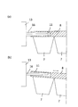
- Sectional drawing of the refrigerator with an ice making apparatus which concerns on this invention It is a side view of an ice making apparatus, (a) shows the horizontal attitude
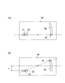
- FIG. 5 is a rear view of an ice making device according to another embodiment, in which (a) shows a horizontal posture of the ice tray, and (b) shows an axially inclined posture of the ice tray.
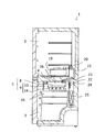
- the refrigerator 1 with an ice making device is set in a refrigerating room 2 set in the upper part, a freezing room 3 set in the lower part of the refrigerating room 2, and an upper part in the freezing room 3.
- the ice making chamber 4 and the ice making device 5 provided in the ice making chamber 4 are further provided.
- the ice making device 5 further supports an ice making tray 8 having a plurality of ice making recesses 7 and an ice making tray 8. And supporting the ice tray 8 in a plurality of postures of a horizontal posture parallel to the horizontal plane and an inclined posture inclined with respect to the horizontal plane. The posture and the inclined posture can be switched.
- the ice tray 8 is formed by arranging a plurality of ice making recesses 7 in, for example, two rows on the left and right and four rows on the front and rear when viewed from the front side of the refrigerator 1, and the plurality of ice making recesses 7 are formed in the same shape. .
- an engagement hole 11 having a horizontally long cross-section is formed to insert and engage a rotation drive shaft 16 to be described later, and the center of the rear side end of the ice tray 8 is formed.
- a both-end supporting shaft 12 having a circular cross section supported by a both-end supporting portion 18 described later is provided.
- the ice tray 8 is provided with an ice making thermistor to detect ice making.
- the support unit 9 includes a drive unit 13 for rotatably supporting the ice tray 8 and a support plate 14 that supports the ice tray 8 and the drive unit 13 and covers the upper side and the periphery thereof.
- the space partitioned by is the ice making chamber 4.
- An ice storage case 15 is provided below the ice making chamber 4 to store the ice made by the ice making device 5.
- the drive unit 13 is provided with a rotary drive shaft 16 that protrudes from the engagement hole 11 of the ice tray 8 to support the ice tray 8 in a cantilevered manner and to rotate.
- the rotation drive shaft 16 rotates around its central axis to rotate the ice tray 8, whereby the ice made is detached from the ice tray 8 and dropped into the ice storage case 15.
- the engagement hole 11 and the insertion site of the rotary drive shaft 16 into the engagement hole 11 are set to a size that allows the insertion site of the rotary drive shaft 16 to be inserted into the engagement hole 11 and engaged with each other It is formed in a flat cross section so that the rotation of the rotation drive shaft 16 can be transmitted to the ice tray 8.
- the engagement hole 11 has a cross-sectional shape that is set to be horizontally long and flat, and the short-side dimension of the cross-sectional shape is longer than the short-side dimension of the cross-sectional shape of the insertion portion of the rotary drive shaft 16 and is inserted. It is set shorter than the longitudinal dimension of the cross-sectional shape of the part.
- the engaging hole 11 and the rotary drive shaft 16 can be gently engaged by inclining the short direction of each other to tilt the ice tray 8, and the flat end portions of the flat plate are rotated by rotating the rotary drive shaft 16. Is pressed against the upper and lower surfaces of the engagement hole 11 so that the ice tray 8 can be supported horizontally and supported horizontally. As a result, the rotational drive shaft 16 is rotated relative to the ice tray 8 around the central axis, and the horizontal position of the ice tray 8 and the axial direction in which the ice tray 8 is inclined in the central axis direction of the rotational drive shaft 16. The inclination posture can be switched.
- a slit-shaped guide portion 17 for guiding the both-end supporting shaft 12 of the ice tray 8 in the vertical direction is formed in a portion of the support plate 14 covering the back side of the ice tray 8.
- the guide portion 17 guides the side of the ice tray 8 opposite to the rotation drive shaft 16 in the vertical direction to prevent the ice tray 8 from being laterally displaced. To do.
- the lower end of the guide portion 17 receives the both-end supported shaft 12 of the ice tray 8 and both the ice tray 8 to the axially tilted posture with the rotary drive shaft 16. It is set as the both-ends support part 18 which supports.
- the double-supported support portion 18 is configured to receive only the double-supported shaft 12 of the ice tray 8, and when the ice tray 8 is switched to the horizontal posture, the double-supported shaft 12 moves upward along the guide portion 17. Thus, the support for the ice tray 8 is released.
- Water to be supplied to the ice tray 8 is stored in a water supply tank 19 provided in the refrigerator compartment 2, and ice is made from the water supply tank 19 through a water supply pump 20, a water supply pipe 21, and a water supply unit 22 set at the discharge port. Water is supplied to the dish 8.
- 23 is a pipe heater
- 24 is a cold air circulation fan
- 25 is an evaporator
- 26 is a tank heater.
- the rotational drive shaft 16 is inserted into the engagement hole 11 of the ice tray 8 to be cantilevered, and the transverse dimension of the cross-sectional shape of the engagement hole 11 is determined at the insertion site of the rotational drive shaft 16. It is set longer than the dimension in the short direction of the cross-sectional shape.
- the rotation drive shaft 16 can be rotated to switch between the horizontal posture and the axially inclined posture of the ice tray 8, and ices of various sizes can be selected by appropriately selecting the posture of the ice tray 8 during ice making. Can be made into ice.
- the rotational drive shaft 16 is rotated in the opposite direction (counterclockwise in FIG. 4) to the direction of icing from the ice tray 8, and both ends of the insertion site of the rotational drive shaft 16 are rotated.
- the portion is pressed against the upper and lower surfaces of the engagement hole 11, and the engagement hole 11 and the rotary drive shaft 16 are strongly engaged to support the ice tray 8 in a horizontal position (FIGS. 1, 2A, 3). (See (a) and FIG. 4 (a)).
- water can be supplied from the water supply unit 22 to the ice tray 8 without spilling water from the ice tray 8.
- the rotary drive shaft 16 When large, medium, and small sizes of ice having different sizes are made after supplying water to the ice tray 8, the rotary drive shaft 16 is rotated in the direction of removing the ice from the ice tray 8 (clockwise in FIG. 4). The flat shape is adjusted in the horizontal direction, and the engagement hole 11 and the rotary drive shaft 16 are gently engaged. In this state, there is a gap between the upper and lower surfaces of the engagement hole 11 and the insertion site of the rotary drive shaft 16, and the ice tray 8 is inclined with respect to the rotary drive shaft 16 by its own weight and the weight of water. The ice tray 8 is supported in an axially inclined posture by being guided downward along the guide portion 17 until the support shaft 12 is supported by the both-end support portions 18 of the support plate 14 (FIG. 2B). 3 (b), see FIG. 4 (b)).
- the water surface 27 can be inclined relative to the ice tray 8 without spilling water from the ice tray 8, and by making ice as it is, a large size can be obtained. Large, medium and small ices of different sizes can be made.
- the horizontal position of the ice tray 8 is maintained without rotating the rotary drive shaft 16, and the ice tray 8.
- the ice surface may be made without inclining the water surface 27.
- the rotary drive shaft 16 is rotated in the direction of removing the ice from the ice tray 8 (clockwise in FIG. 4), and the both ends of the insertion portion of the rotary drive shaft 16 are turned upside down from the horizontal posture at the time of water supply. Then, the ice tray 8 is pressed against the upper and lower surfaces of the engagement hole 11 and supported in a horizontal posture (see FIG. 4C). Furthermore, by rotating the rotary drive shaft 16 in the direction of deicing from the ice tray 8 (clockwise in FIG. 4) while restricting the rotation of the rear side end of the ice tray 8 with a stopper (not shown), The ice tray 8 is twisted to release the ice.
- the stopper After removing the ice from the ice tray 8, the stopper is released, the ice tray 8 is rotated by the rotary drive shaft 16, and the ice is dropped into the ice storage case 15 and stored.
- this invention is not limited to said embodiment, A change can be suitably added within the scope of the present invention.
- the insertion hole may be formed in the ice tray 8 by forming the engagement hole in the rotation drive shaft 16.
- the cross-sectional shape of the insertion site is changed in the axial direction, and the insertion site is moved in the axial direction to switch the engagement state with the engagement hole. You may do it.
- an engaging portion that can be engaged with the rotation drive shaft 16 is formed in the ice tray 8 and the engagement state between the rotation drive shaft 16 and the engagement portion is switched. Accordingly, the horizontal posture of the ice tray 8 and the axially inclined posture of the ice tray 8 may be switched.
- the rotation drive shaft 16 and the both-end support portion 18 may be both-end supported.
- the engagement plate 28 is provided at the front side end of the ice tray 8 to form the slide grooves 29 and 30, and the engagement protrusions 31 and 32 are formed on the rotary drive shaft 16.
- the front end of the ice tray 8 can be moved up and down to switch between the horizontal posture of the ice tray 8 and the axially inclined posture of the ice tray 8.
- the slide groove 29 is formed in the horizontal direction and the engagement protrusion 31 is engaged, and the slide groove 30 is formed in the substantially vertical direction and the engagement protrusion 32 is engaged.
- the engaging projection 32 is positioned at the lower end of the slide groove 30 to place the ice tray 8 in a horizontal posture, and the ice making tray 8 is rotated by rotating the rotary drive shaft 16 clockwise from this state. And can be deiced.
- the engaging protrusion 32 moves upward along the slide groove 30 as shown in FIG. While the engagement protrusion 31 moves to the right along the slide groove 29, the engagement plate 28 is pushed down by the height (h), so that the ice tray 8 is inclined in the axial direction.
- the rotary drive shaft 16 is rotated in the direction of separating the ice from the ice tray 8 (clockwise in FIG. 6) and stopped.
- the water surface 27 is inclined relative to the ice tray 8 in the axially inclined posture shown in FIG.
- the rotary drive shaft 16 is further rotated to separate the ice, whereby large and small ices having different sizes can be made in the left and right ice making recesses 7.
- the insertion hole 11 and the rotational drive shaft 16 are set in a flat shape so that the ice tray 8 can be set in an axially inclined posture, and the ice tray 8 can be stopped during rotation.
- the tilting direction perpendicular to the axis it may be possible to set the tilting direction perpendicular to the axis.
- the ice tray 8 can be switched to both the axially inclined posture and the axially inclined posture, and uniform size ice, large / medium size ice, or large / small size ice can be appropriately selected. it can.
- the number of the plurality of ice making recesses 7 may be any number and may not necessarily have the same shape.
- the rotation drive shaft 16 is not only used for the switching of the attitude of the ice tray 8 and the rotational drive of the ice tray 8 at the time of deicing, but a dedicated switching structure is provided to switch the attitude of the ice tray 8. Also good.
- the refrigerator 1 with an ice making device is an ice making chamber 4 equipped with an ice making device 5, and the ice making device 5 further has an ice making tray 8 having a plurality of ice making recesses 7. And a support portion 9 that supports the ice tray 8.
- the support portion 9 can support the ice tray 8 in a horizontal posture parallel to the horizontal plane and an inclined posture inclined with respect to the horizontal plane. The horizontal posture and the inclined posture can be switched.
- the ice tray 8 can be supported in an inclined posture inclined with respect to the horizontal plane, a plurality of types of ice having different sizes can be made by one ice making. Moreover, since it is possible to switch between the horizontal posture and the inclined posture of the ice tray 8, it is possible to appropriately select whether to make ice of a uniform size or to make a plurality of types of ice having different sizes.
- the support unit 9 is provided with a rotation drive shaft 16 that supports and rotates the ice tray 8, and the ice tray 8 is rotated by rotating the rotation drive shaft 16 around its central axis so that it can be deiced. Also good.
- the rotation drive shaft 16 is provided to the support portion 9 for switching the attitude of the ice tray 8 and the ice tray 8 is rotated by the rotation drive shaft 16 to separate the ice. 8 can be used both for switching the posture and for removing the ice from the ice tray 8.
- the rotary drive shaft 16 may be cantilevered to support the ice tray 8. According to this configuration, since the ice tray 8 is cantilevered, it is possible to switch the posture of the ice tray 8 by moving the end of the ice tray 8 slightly by moving the end of the ice tray 8 slightly. The structure for switching the posture of the ice tray 8 can be reduced in size.
- the support portion is provided with an engaging portion formed on the ice tray 8 so as to be engageable with the rotation drive shaft 16, and by switching the engagement state between the rotation drive shaft 16 and the engagement portion, the ice tray 8 can be placed horizontally. It is possible to switch between the attitude and the axial inclination attitude that is inclined in the central axis direction of the rotation drive shaft 16 in the inclination attitude of the ice tray. According to this configuration, since the engaging portion is formed in the ice tray 8 and is engaged with the rotational drive shaft 16, the rotational drive shaft 16 for separating the ice from the ice tray 8 can be removed simply by switching the engagement state. It is possible to switch the posture of the ice tray 8 by using it.
- the ice tray 8 is formed with an engagement hole 11 into which the rotation drive shaft 16 is inserted and engaged, and the cross-sectional shape of the engagement hole 11 is set to be a horizontally long flat shape.
- the insertion portion of the engagement hole 11 is set to have a flat cross-sectional shape that can be inserted into the engagement hole 11, and the short-side dimension of the cross-sectional shape of the engagement hole 11 is set as the insertion portion of the rotary drive shaft 16.
- the engagement hole 11 and the insertion site of the rotary drive shaft 16 are set to have a flat cross section, and the flat short dimension of the engagement hole 11 is set to the flat short width of the rotary drive shaft 16. Since it is set to be longer than the directional dimension, the engagement state between the engagement hole 11 and the rotation drive shaft 16 can be switched by appropriately rotating the rotation drive shaft 16.
- both flat end portions of the rotation drive shaft 16 are pressed against the upper and lower surfaces of the engagement hole 11 and the engagement hole 11 and the rotation drive shaft 16 are strongly engaged.
- the ice tray 8 can be switched to the horizontal posture. Further, by rotating the rotary drive shaft 16 as appropriate, the engagement hole 11 and the rotary drive shaft 16 are gently engaged with each other in accordance with the flat short direction of the engagement hole 11 and the rotary drive shaft 16.
- the ice tray 8 can be tilted with respect to the rotational drive shaft 16 to switch the ice tray 8 to the axially inclined posture.
- the ice making tray 8 is set to an axially inclined posture by rotating the rotary drive shaft 16 to adjust the flat shape of the insertion site in the horizontal direction, and in the direction opposite to the direction in which the ice making tray 8 is rotated and deiced.
- the ice tray 8 may be set in a horizontal posture by rotating the rotation drive shaft 16. According to this configuration, when the ice tray 8 is set to the horizontal posture, the rotation drive shaft 16 is rotated in the direction opposite to the direction of deicing, so that the ice tray 8 is rotated by an accurate rotation amount in the middle of the deicing direction. It is not necessary to stop the drive shaft 16, and the horizontal position of the ice tray 8 can be more reliably maintained.
- both-end support part 18 that supports the ice tray 8 in an axially inclined posture with respect to the rotation drive shaft 16.
- the part 18 may be disengageable from supporting the ice tray 8 in a horizontal posture.
- a guide portion 17 that guides the side of the ice tray 8 opposite to the rotation drive shaft 16 in the vertical direction may be provided. According to this configuration, since the guide portion 17 guides the opposite side of the ice tray 8 in the vertical direction, it is possible to prevent lateral displacement of the ice tray 8 supported in a cantilever manner.
- the rotation drive shaft 16 by rotating the rotation drive shaft 16 around its central axis and rotating the ice tray 8, the horizontal position of the ice tray 8 and the direction of the central axis of the rotation drive shaft 16 in the inclined position of the ice tray 8 It may be possible to switch between the axial inclination postures inclined in the orthogonal direction. According to this configuration, since the ice tray 8 is rotated by the rotation drive shaft 16 to be inclined in the axial direction, the structure for switching the posture of the ice tray 8 can be simplified.
- a water supply unit 22 for supplying water to the ice tray 8 may be provided, and the ice tray 8 may be in a horizontal posture when water is supplied from the water supply unit 22 and in an inclined posture after water supply. According to this configuration, since the ice tray 8 is set in a horizontal posture when water is supplied from the water supply unit 22, water can be supplied without spilling water from the ice tray 8.
- a plurality of ice making recesses may be formed in the same shape. According to this configuration, it is possible not only to make a plurality of types of ice with different sizes by making the ice tray 8 in an inclined posture, but also to make ice of a uniform size by making the ice tray 8 in a horizontal posture.
- a water supply tank 19 for storing water to be supplied to the ice tray 8 may be provided in the refrigerator compartment 2. According to this configuration, since the water supply tank 19 is provided in the refrigerator compartment 2, it is possible to save the trouble of supplying water to the ice tray 8 and to keep the water supplied to the ice tray 8 in the refrigerator compartment 2. The time required for ice making can be shortened.
Landscapes
- Engineering & Computer Science (AREA)
- Physics & Mathematics (AREA)
- Mechanical Engineering (AREA)
- Thermal Sciences (AREA)
- General Engineering & Computer Science (AREA)
- Production, Working, Storing, Or Distribution Of Ice (AREA)
Abstract
製氷室4に製氷装置5を装備する。製氷装置5に、複数の製氷凹部7を有する製氷皿8を設ける。製氷装置5に、製氷皿8を支持する支持部9を設ける。支持部9で製氷皿8を水平面と平行な水平姿勢に支持可能とする。支持部9で製氷皿8を水平面に対して傾斜した傾斜姿勢に支持可能とする。製氷皿8の水平姿勢と傾斜姿勢とを切換可能とする。製氷皿8を傾斜姿勢に切り換えて水面27を傾けることにより、1回の製氷で複数種類の大きさの氷を得る。
Description
本発明は、製氷室に製氷装置が装備された製氷装置付冷蔵庫に関するものである。
一般に、冷蔵庫の製氷室には、水を溜めて製氷するための複数の製氷凹部を有する製氷皿が設けられ、その複数の製氷凹部が同一形状に形成されて、同一形状の氷を製氷するようになっている。
このような同一形状の氷を製氷する冷蔵庫に対し、例えば特許文献1には、製氷皿への給水量を変化させて、異なる大きさの氷を製氷する冷蔵庫が開示されている。また、例えば特許文献2には、製氷皿の製氷凹部として大氷粒製氷用や小氷粒製氷用の大きさの異なる凹形状部を形成して、異なる大きさの氷を製氷する冷蔵庫が開示されている。
ところが、特許文献1の冷蔵庫は、製氷皿への給水量を変化させるものであり、製氷ごとに給水量を変化させて異なる大きさの氷を製氷できるものの、1回の製氷で得られる氷は同じ大きさであり、複数種類の大きさの氷を得るには、複数回の製氷を必要とする分、その製氷に要する時間が長くなる。
また、特許文献2の冷蔵庫は、製氷皿に大きさの異なる製氷凹部を形成したものであり、1回の製氷で複数種類の大きさの氷を得ることができるものの、製氷ごとに氷の大きさを切り換えることはできない。
本発明は、1回の製氷で複数種類の大きさの氷を得ることができると共に、製氷ごとに氷の大きさを切り換えることのできる製氷装置付冷蔵庫の提供を目的とする。
上記目的を達成するために、本発明に係る製氷装置付冷蔵庫は、製氷室に製氷装置が装備された製氷装置付冷蔵庫であって、前記製氷装置は、複数の製氷凹部を有する製氷皿と、該製氷皿を支持する支持部とを備え、前記支持部は、前記製氷皿を水平面と平行な水平姿勢及び水平面に対して傾斜した傾斜姿勢に支持可能とされ、製氷皿の水平姿勢と傾斜姿勢とを切換可能とされたものである。
また、前記支持部は、製氷皿を支持すると共に回転駆動する回転駆動軸を備え、該回転駆動軸がその中心軸周りに回転して製氷皿を回転させることにより離氷可能とされたものであってもよい。
また、前記回転駆動軸は、前記製氷皿を片持ち支持可能とされたものであってもよい。
また、前記支持部は、回転駆動軸に係合可能に製氷皿に形成された係合部を備え、前記回転駆動軸と係合部との係合状態を切り換えることにより、製氷皿の水平姿勢と、製氷皿の傾斜姿勢のうちの回転駆動軸の中心軸方向において傾斜する軸方向傾斜姿勢と、を切換可能とされたものであってもよい。
また、前記製氷皿に、回転駆動軸を挿入されて係合する係合穴が形成され、該係合穴の断面形状が横長扁平状に設定されると共に、前記回転駆動軸の係合穴への挿入部位が係合穴に挿入可能な大きさの断面扁平状に設定され、前記係合穴の断面形状の短手方向寸法が、回転駆動軸の前記挿入部位の断面形状の短手方向寸法よりも長く、かつ前記挿入部位の断面形状の長手方向寸法よりも短く設定され、前記回転駆動軸が中心軸周りに製氷皿に対して相対的に回転することにより、製氷皿の水平姿勢と、製氷皿の傾斜姿勢のうちの回転駆動軸の中心軸方向において傾斜する軸方向傾斜姿勢と、を切換可能とされたものであってもよい。
また、前記回転駆動軸を回転させて挿入部位の扁平形状を水平方向に合わせることによって製氷皿が軸方向傾斜姿勢に設定され、前記製氷皿を回転させて離氷させる方向とは反対方向に回転駆動軸を回転させることによって製氷皿が水平姿勢に設定されるものであってもよい。
また、前記回転駆動軸がその中心軸周りに回転して製氷皿を回転させることにより、製氷皿の水平姿勢と、製氷皿の傾斜姿勢のうちの回転駆動軸の中心軸方向と直交する方向において傾斜する軸直方向傾斜姿勢と、を切換可能とされたものであってもよい。
また、前記製氷皿に給水する給水部が設けられ、前記製氷皿は、給水部からの給水時に水平姿勢とされ、給水後に傾斜姿勢とされるものであってもよい。
以上のとおり、本発明によると、製氷皿の水平姿勢と傾斜姿勢とを切換可能とするので、1回の製氷で複数種類の大きさの氷を得ることができると共に、製氷ごとに氷の大きさを変更することができる。
以下、本発明に係る製氷装置付冷蔵庫の実施の形態について、図面を用いて説明する。
図1~図4に示すように、製氷装置付冷蔵庫1は、その上部に設定された冷蔵室2と、冷蔵室2の下方に設定された冷凍室3と、冷凍室3の室内上部に設定された製氷室4と、製氷室4に装備した製氷装置5と、を備えたものであり、さらに、その製氷装置5に、複数の製氷凹部7を有する製氷皿8と、製氷皿8を支持する支持部9と、を備え、その支持部9によって、製氷皿8を、水平面と平行な水平姿勢と、水平面に対して傾斜した傾斜姿勢と、の複数種類の姿勢に支持すると共に、その水平姿勢と傾斜姿勢とを切換可能としたものである。
製氷皿8は、複数の製氷凹部7を例えば冷蔵庫1の正面側から見て左右に2列で前後に4列に並設してなり、その複数の製氷凹部7が同一形状に形成されている。この製氷皿8の正面側端部の中央には、後述する回転駆動軸16を挿入して係合する断面横長扁平状の係合穴11が形成され、製氷皿8の背面側端部の中央には、後述する両持ち支持部18で支持される断面円形の両持ち軸12が突設されている。なお、製氷皿8には製氷サーミスターが設けられ、製氷されたことを検知するようになっている。
支持部9は、製氷皿8を回転可能に支持するための駆動部13と、製氷皿8及び駆動部13を支持すると共に、その上方及び周囲を覆う支持板14と、を備え、支持板14で仕切られた空間が製氷室4とされる。製氷室4の下方には、貯氷ケース15が設けられ、製氷装置5で製氷した氷を貯めるようになっている。
図2~図4に示すように、駆動部13には、製氷皿8の係合穴11に挿入されて製氷皿8を片持ち支持すると共に回転駆動する回転駆動軸16が突設され、この回転駆動軸16がその中心軸周りに回転して製氷皿8を回転させることにより、製氷した氷を製氷皿8から離氷して貯氷ケース15に落下させるようになっている。
係合穴11と回転駆動軸16の係合穴11への挿入部位とは、回転駆動軸16の挿入部位を係合穴11に挿入可能な大きさに設定されると共に、互いに係合して回転駆動軸16の回転を製氷皿8の伝達可能なよう断面扁平状に形成されている。係合穴11は、その断面形状を横長扁平状に設定されると共に、その断面形状の短手方向寸法が、回転駆動軸16の挿入部位の断面形状の短手方向寸法よりも長く、かつ挿入部位の断面形状の長手方向寸法よりも短く設定されている。
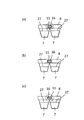
係合穴11及び回転駆動軸16は、互いの短手方向を合わせることによって、緩やかに係合して製氷皿8を傾けることができ、回転駆動軸16を回転させてその扁平形状の両端部を係合穴11の上下面に圧接することによって、強く係合して製氷皿8を水平に支持することができる。これにより、回転駆動軸16を中心軸周りに製氷皿8に対して相対的に回転させて、製氷皿8の水平姿勢と、製氷皿8が回転駆動軸16の中心軸方向において傾斜する軸方向傾斜姿勢と、を切り換えることができる。
支持板14のうちの製氷皿8の背面側を覆う部位には、製氷皿8の両持ち軸12を上下方向に案内するスリット状のガイド部17が形成されている。ガイド部17は、製氷皿8の水平姿勢と軸方向傾斜姿勢とを切り換える際に、製氷皿8のうちの回転駆動軸16と反対側を上下方向に案内して、製氷皿8の横ずれを阻止する。
ガイド部17の下端は、製氷皿8を軸方向傾斜姿勢に切り換えた際、製氷皿8の両持ち軸12を受けて、回転駆動軸16との間で製氷皿8を軸方向傾斜姿勢に両持ち支持する両持ち支持部18とされる。両持ち支持部18は、製氷皿8の両持ち軸12を受けるだけの構造とされ、製氷皿8を水平姿勢に切り換えた際、ガイド部17に沿って両持ち軸12が上方に移動することにより、製氷皿8に対する支持を解除するようになっている。
製氷皿8に給水する水は、冷蔵室2に設けられた給水タンク19に貯められ、この給水タンク19から給水ポンプ20、給水パイプ21及びその吐出口に設定された給水部22を介して製氷皿8に給水される。なお、図1において、23はパイプヒーター、24は冷気循環ファン、25は蒸発器、26はタンクヒーターである。
上記構成によれば、製氷皿8の係合穴11に回転駆動軸16を挿入して片持ち支持すると共に、係合穴11の断面形状の短手方向寸法を回転駆動軸16の挿入部位の断面形状の短手方向寸法よりも長く設定するようにしている。これにより、回転駆動軸16を回転させて製氷皿8の水平姿勢と軸方向傾斜姿勢とを切り換えることができ、製氷時の製氷皿8の姿勢を適宜選択することにより、種々の大きさの氷を製氷することができる。
具体的にその手順を説明すると、まず、製氷皿8から離氷させる方向とは反対方向(図4における反時計回り)に回転駆動軸16を回転させて、回転駆動軸16の挿入部位の両端部を係合穴11の上下面に圧接し、係合穴11と回転駆動軸16とを強く係合して製氷皿8を水平姿勢に支持する(図1、図2(a)、図3(a)、図4(a)参照)。この水平姿勢の製氷皿8に給水することにより、製氷皿8から水をこぼすことなく、給水部22から製氷皿8に給水することができる。
製氷皿8に給水した後、大きさが異なる大中小の氷を製氷する場合には、製氷皿8から離氷させる方向(図4における時計回り)に回転駆動軸16を回転させて挿入部位の扁平形状を水平方向に合わせ、係合穴11と回転駆動軸16とを緩やかに係合させる。この状態では、係合穴11の上下面と回転駆動軸16の挿入部位との間に隙間があり、回転駆動軸16に対して製氷皿8がその自重及び水の重量で傾きながら、その両持ち軸12が支持板14の両持ち支持部18で支持されるまでガイド部17に沿って下方に案内されて、製氷皿8が軸方向傾斜姿勢に支持される(図2(b)、図3(b)、図4(b)参照)。
この場合、給水後に製氷皿8を傾斜姿勢にするので、製氷皿8から水をこぼすことなく、製氷皿8に対して相対的に水面27を傾斜させることができ、このまま製氷することにより、大きさが異なる大中小の氷を製氷することができる。
また、水平姿勢の製氷皿8に給水した後、複数の同じ大きさの氷を製氷する場合には、回転駆動軸16を回転させることなく製氷皿8の水平姿勢を維持して、製氷皿8に対して水面27を傾斜させることなく製氷すればよい。
製氷後、製氷皿8から離氷させる方向(図4における時計回り)に回転駆動軸16を回転させ、回転駆動軸16の挿入部位の両端部を給水時の水平姿勢とは上下を反対にしつつ、係合穴11の上下面に圧接し、製氷皿8を水平姿勢に支持する(図4(c)参照)。さらに、製氷皿8の背面側端部の回転をストッパー(図示せず)で規制しつつ、製氷皿8から離氷させる方向(図4における時計回り)に回転駆動軸16を回転させることによって、製氷皿8を捻じって離氷する。
製氷皿8から離氷した後、ストッパーを解除し、回転駆動軸16で製氷皿8を回転させて、氷を貯氷ケース15に落下させて貯める。
なお、本発明は、上記の実施の形態に限定されるものではなく、本発明の範囲内において、適宜変更を加えることができる。例えば、製氷皿8に係合穴11を形成して回転駆動軸16の挿入部位を挿入する代わりに、回転駆動軸16に係合穴を形成して製氷皿8に挿入突起を形成してもよい。また、係合穴11及び挿入部位を断面扁平状に設定する代わりに、挿入部位の断面形状を軸方向で変化させ、挿入部位を軸方向に移動させて係合穴との係合状態を切り換えるようにしてもよい。すなわち、支持部の一部を構成するものとして、製氷皿8に、回転駆動軸16に係合可能な係合部を形成し、回転駆動軸16と係合部との係合状態を切り換えることにより、製氷皿8の水平姿勢と製氷皿8の軸方向傾斜姿勢とを切り換えるようにしてもよい。
また、水平姿勢の製氷皿8を回転駆動軸16で片持ち支持する代わりに、回転駆動軸16と両持ち支持部18とで両持ち支持するようにしてもよい。具体的には、例えば、図5に示すように、製氷皿8の正面側端部に係合板28を設けてスライド溝29、30を形成し、回転駆動軸16に係合突起31、32を設けてスライド溝29、30に沿って移動させることにより、製氷皿8の正面側端部を上下動させて製氷皿8の水平姿勢と製氷皿8の軸方向傾斜姿勢とを切り換えることができる。
図5において、スライド溝29は水平方向に形成されて係合突起31が係合し、スライド溝30は略上下方向に形成されて係合突起32が係合している。図5(a)では、係合突起32がスライド溝30の下端に位置して製氷皿8を水平姿勢にし、この状態から回転駆動軸16を時計回りに回転させることにより、製氷皿8が回転して離氷させることができる。また、図5(a)の状態から回転駆動軸16を反時計回りに回転させることにより、図5(b)のように、係合突起32がスライド溝30に沿って上方に移動すると共に、係合突起31がスライド溝29に沿って右方に移動しながら係合板28を高さ(h)だけ押し下げて、製氷皿8を軸方向傾斜姿勢にする。
また、図6に示すように、製氷皿8の水平姿勢と傾斜姿勢とを切り換えるには、製氷皿8を軸方向傾斜姿勢にするだけでなく、回転駆動軸16をその中心軸周りに回転させて製氷皿8を回転させることにより、製氷皿8の水平姿勢と、製氷皿8が回転駆動軸16の中心軸方向と直交する方向において傾斜する軸直方向傾斜姿勢と、を切り換えるようにしてもよい。
この場合、図6(a)に示す製氷皿8の水平姿勢で給水した後、製氷皿8から離氷させる方向(図6における時計回り)に回転駆動軸16を回転させて停止し、製氷皿8を図6(b)に示す軸直方向傾斜姿勢にして製氷皿8に対して相対的に水面27を傾斜させる。この軸直方向傾斜姿勢で製氷した後、回転駆動軸16をさらに回転させて離氷させることにより、左右の製氷凹部7で大きさの異なる大小の氷を製氷することができる。
さらに、上記のように係合穴11及び回転駆動軸16の挿入部位を扁平状に設定して製氷皿8を軸方向傾斜姿勢に設定可能とすると共に、製氷皿8を回転途中で停止可能にして軸直方向傾斜姿勢に設定可能としてもよい。これにより、製氷皿8を軸方向傾斜姿勢及び軸直方向傾斜姿勢の両方に切換可能として、均一な大きさの氷、大中小の大きさ氷又は大小の大きさの氷を適宜選択することができる。
また、複数の製氷凹部7は、その数がいくつであってもよく、また、必ずしも同一形状でなくてもよい。また、回転駆動軸16を製氷皿8の姿勢の切換と離氷時の製氷皿8の回転駆動とに兼用するだけでなく、専用の切換構造を設けて製氷皿8の姿勢を切り換えるようにしてもよい。
以上の説明から明らかな通り、本発明に係る製氷装置付冷蔵庫1は、製氷室4に製氷装置5を装備したものであり、さらに、製氷装置5が、複数の製氷凹部7を有する製氷皿8と、この製氷皿8を支持する支持部9とを備え、その支持部9を、製氷皿8を水平面と平行な水平姿勢及び水平面に対して傾斜した傾斜姿勢に支持可能とし、製氷皿8の水平姿勢と傾斜姿勢とを切換可能としたものである。
この構成によれば、製氷皿8を水平面に対して傾斜した傾斜姿勢に支持可能とするので、一度の製氷で大きさの異なる複数種類の氷を作ることができる。しかも、製氷皿8の水平姿勢と傾斜姿勢とを切換可能とするので、均一な大きさの氷を作るか、あるいは大きさの異なる複数種類の氷を作るかを適宜選択することができる。
さらに、支持部9に、製氷皿8を支持すると共に回転駆動する回転駆動軸16を備え、この回転駆動軸16をその中心軸周りに回転させて製氷皿8を回転させることにより離氷可能としてもよい。この構成によれば、製氷皿8の姿勢を切り換える支持部9に回転駆動軸16を備えて、この回転駆動軸16で製氷皿8を回転させて離氷するので、回転駆動軸16を製氷皿8の姿勢の切換と製氷皿8からの離氷とに対して兼用することができる。
また、回転駆動軸16を、製氷皿8を片持ち支持可能としてもよい。この構成によれば、製氷皿8を片持ち支持するので、製氷皿8の端部をわずかに動かすだけで、反対側の端部を大きく移動させて製氷皿8の姿勢を切り換えることができ、製氷皿8の姿勢を切り換えるための構造の小型化を図ることができる。
また、支持部に、回転駆動軸16に係合可能に製氷皿8に形成した係合部を備え、回転駆動軸16と係合部との係合状態を切り換えることにより、製氷皿8の水平姿勢と、製氷皿の傾斜姿勢のうちの回転駆動軸16の中心軸方向において傾斜する軸方向傾斜姿勢と、を切換可能としてもよい。この構成によれば、製氷皿8に係合部を形成して回転駆動軸16に係合させるので、その係合状態を切り換えるだけで、製氷皿8から離氷させるための回転駆動軸16を用いて製氷皿8の姿勢を切り換えることができる。
より具体的には、製氷皿8に、回転駆動軸16を挿入して係合する係合穴11を形成し、この係合穴11の断面形状を横長扁平状に設定すると共に、回転駆動軸16の係合穴11への挿入部位を係合穴11に挿入可能な大きさの断面扁平状に設定し、係合穴11の断面形状の短手方向寸法を、回転駆動軸16の挿入部位の断面形状の短手方向寸法よりも長く、かつ挿入部位の断面形状の長手方向寸法よりも短く設定し、回転駆動軸16を中心軸周りに製氷皿8に対して相対的に回転させることにより、製氷皿8の水平姿勢と、製氷皿8の傾斜姿勢のうちの回転駆動軸16の中心軸方向において傾斜する軸方向傾斜姿勢と、を切換可能とするようにしてもよい。
この構成によれば、係合穴11と回転駆動軸16の挿入部位とを断面扁平状に設定し、係合穴11の扁平形状の短手方向寸法を回転駆動軸16の扁平形状の短手方向寸法よりも長く設定するので、回転駆動軸16を適宜回転させて、係合穴11と回転駆動軸16との係合状態を切り換えることができる。
すなわち、回転駆動軸16を適宜回転させることにより、回転駆動軸16の扁平形状の両端部を係合穴11の上下面に圧接して、係合穴11と回転駆動軸16とを強く係合し、製氷皿8を水平姿勢に切り換えることができる。また、回転駆動軸16を適宜回転させることにより、係合穴11及び回転駆動軸16の扁平形状の短手方向を合わせて、係合穴11と回転駆動軸16とを緩やかに係合し、回転駆動軸16に対して製氷皿8を傾けて、製氷皿8を軸方向傾斜姿勢に切り換えることができる。
さらに、回転駆動軸16を回転させて挿入部位の扁平形状を水平方向に合わせることによって製氷皿8を軸方向傾斜姿勢に設定し、製氷皿8を回転させて離氷させる方向とは反対方向に回転駆動軸16を回転させることによって製氷皿8を水平姿勢に設定するようにしてもよい。この構成によれば、製氷皿8を水平姿勢に設定するのに、離氷させる方向とは反対方向に回転駆動軸16を回転させるので、離氷させる方向の途中において、正確な回転量で回転駆動軸16を止める必要がなく、より確実に製氷皿8の水平姿勢を維持することができる。
また、製氷皿8のうちの回転駆動軸16と反対側に、回転駆動軸16との間で製氷皿8を軸方向傾斜姿勢に両持ち支持する両持ち支持部18を設け、この両持ち支持部18を、水平姿勢の製氷皿8に対する支持を解除可能としてもよい。この構成によれば、軸方向傾斜姿勢の製氷皿8を回転駆動軸16と両持ち支持部18とで両持ち支持するので、製氷皿8を傾斜させたまま安定して支持して、その軸方向傾斜姿勢を維持することができる。
また、製氷皿8のうちの回転駆動軸16と反対側を上下方向に案内するガイド部17を設けてもよい。この構成によれば、ガイド部17で製氷皿8の反対側を上下方向に案内するので、片持ち支持した製氷皿8の横ずれを阻止することができる。
また、回転駆動軸16をその中心軸周りに回転させて製氷皿8を回転させることにより、製氷皿8の水平姿勢と、製氷皿8の傾斜姿勢のうちの回転駆動軸16の中心軸方向と直交する方向において傾斜する軸直方向傾斜姿勢と、を切換可能としてもよい。この構成によれば、回転駆動軸16で製氷皿8を回転させて軸直方向傾斜姿勢にするので、製氷皿8の姿勢を切り換えるための構造を簡単にすることができる。
また、製氷皿8に給水する給水部22を設け、製氷皿8を、給水部22からの給水時に水平姿勢とし、給水後に傾斜姿勢とするようにしてもよい。この構成によれば、給水部22からの給水時に製氷皿8を水平姿勢にするので、製氷皿8から水をこぼすことなく給水することができる。
また、複数の製氷凹部を同一形状に形成してもよい。この構成によれば、製氷皿8を傾斜姿勢にして大きさの異なる複数種類の氷を作るだけでなく、製氷皿8を水平姿勢にして均一な大きさの氷を作ることができる。
また、冷蔵室2に、製氷皿8に給水する水を貯める給水タンク19を設けてもよい。この構成によれば、冷蔵室2に給水タンク19を設けるので、製氷皿8への給水の手間を省くことができると共に、製氷皿8に給水する水を冷蔵室2で冷やしておくことができ、製氷に要する時間を短くすることができる。
1 製氷装置付冷蔵庫
2 冷蔵室
3 冷凍室
4 製氷室
5 製氷装置
7 製氷凹部
8 製氷皿
9 支持部
11 係合穴
12 両持ち軸
13 駆動部
14 支持板
15 貯氷ケース
16 回転駆動軸
17 ガイド部
18 両持ち支持部
19 給水タンク
22 給水部
27 水面
28 係合板
29、30 スライド溝
31、32 係合突起
2 冷蔵室
3 冷凍室
4 製氷室
5 製氷装置
7 製氷凹部
8 製氷皿
9 支持部
11 係合穴
12 両持ち軸
13 駆動部
14 支持板
15 貯氷ケース
16 回転駆動軸
17 ガイド部
18 両持ち支持部
19 給水タンク
22 給水部
27 水面
28 係合板
29、30 スライド溝
31、32 係合突起
Claims (5)
- 製氷室に製氷装置が装備された製氷装置付冷蔵庫であって、前記製氷装置は、複数の製氷凹部を有する製氷皿と、該製氷皿を支持する支持部とを備え、前記支持部は、前記製氷皿を水平面と平行な水平姿勢及び水平面に対して傾斜した傾斜姿勢に支持可能とされ、製氷皿の水平姿勢と傾斜姿勢とを切換可能とされたことを特徴とする製氷装置付冷蔵庫。
- 前記支持部は、製氷皿を支持すると共に回転駆動する回転駆動軸を備え、該回転駆動軸がその中心軸周りに回転して製氷皿を回転させることにより離氷可能とされたことを特徴とする請求項1に記載の製氷装置付冷蔵庫。
- 前記回転駆動軸は、前記製氷皿を片持ち支持可能とされたことを特徴とする請求項2に記載の製氷装置付冷蔵庫。
- 前記製氷皿に、回転駆動軸を挿入されて係合する係合穴が形成され、該係合穴の断面形状が横長扁平状に設定されると共に、前記回転駆動軸の係合穴への挿入部位が係合穴に挿入可能な大きさの断面扁平状に設定され、前記係合穴の断面形状の短手方向寸法が、回転駆動軸の前記挿入部位の断面形状の短手方向寸法よりも長く、かつ前記挿入部位の断面形状の長手方向寸法よりも短く設定され、前記回転駆動軸が中心軸周りに製氷皿に対して相対的に回転することにより、製氷皿の水平姿勢と、製氷皿の傾斜姿勢のうちの回転駆動軸の中心軸方向において傾斜する軸方向傾斜姿勢と、を切換可能とされたことを特徴とする請求項3に記載の製氷装置付冷蔵庫。
- 前記回転駆動軸がその中心軸周りに回転して製氷皿を回転させることにより、製氷皿の水平姿勢と、製氷皿の傾斜姿勢のうちの回転駆動軸の中心軸方向と直交する方向において傾斜する軸直方向傾斜姿勢と、を切換可能とされたことを特徴とする請求項2、3又は4に記載の製氷装置付冷蔵庫。
Applications Claiming Priority (2)
| Application Number | Priority Date | Filing Date | Title |
|---|---|---|---|
| JP2013160319A JP2015031429A (ja) | 2013-08-01 | 2013-08-01 | 製氷装置付冷蔵庫 |
| JP2013-160319 | 2013-08-01 |
Publications (1)
| Publication Number | Publication Date |
|---|---|
| WO2015015822A1 true WO2015015822A1 (ja) | 2015-02-05 |
Family
ID=52431375
Family Applications (1)
| Application Number | Title | Priority Date | Filing Date |
|---|---|---|---|
| PCT/JP2014/054281 Ceased WO2015015822A1 (ja) | 2013-08-01 | 2014-02-24 | 製氷装置付冷蔵庫 |
Country Status (2)
| Country | Link |
|---|---|
| JP (1) | JP2015031429A (ja) |
| WO (1) | WO2015015822A1 (ja) |
Cited By (1)
| Publication number | Priority date | Publication date | Assignee | Title |
|---|---|---|---|---|
| EP4027079A1 (en) * | 2021-01-11 | 2022-07-13 | Arçelik Anonim Sirketi | A cooling appliance having an ice maker assembly |
Citations (2)
| Publication number | Priority date | Publication date | Assignee | Title |
|---|---|---|---|---|
| JP2006078098A (ja) * | 2004-09-10 | 2006-03-23 | Hitachi Home & Life Solutions Inc | 冷蔵庫 |
| JP2013040729A (ja) * | 2011-08-18 | 2013-02-28 | Sharp Corp | 冷蔵庫 |
-
2013
- 2013-08-01 JP JP2013160319A patent/JP2015031429A/ja active Pending
-
2014
- 2014-02-24 WO PCT/JP2014/054281 patent/WO2015015822A1/ja not_active Ceased
Patent Citations (2)
| Publication number | Priority date | Publication date | Assignee | Title |
|---|---|---|---|---|
| JP2006078098A (ja) * | 2004-09-10 | 2006-03-23 | Hitachi Home & Life Solutions Inc | 冷蔵庫 |
| JP2013040729A (ja) * | 2011-08-18 | 2013-02-28 | Sharp Corp | 冷蔵庫 |
Cited By (1)
| Publication number | Priority date | Publication date | Assignee | Title |
|---|---|---|---|---|
| EP4027079A1 (en) * | 2021-01-11 | 2022-07-13 | Arçelik Anonim Sirketi | A cooling appliance having an ice maker assembly |
Also Published As
| Publication number | Publication date |
|---|---|
| JP2015031429A (ja) | 2015-02-16 |
Similar Documents
| Publication | Publication Date | Title |
|---|---|---|
| US10928114B2 (en) | Ice maker, refrigerator having the same, and method for making ice | |
| BRPI0924977B1 (pt) | Refrigerador com dispositivo de fazer gelo | |
| KR102432022B1 (ko) | 제빙장치 | |
| EP2096384B1 (en) | Method of controlling ice making assembly for refrigerator | |
| US11573040B2 (en) | Refrigerator | |
| EP2539648B1 (en) | Ice maker, refrigerator having the same, and method for supplying ice thereof | |
| ES2909780T3 (es) | Dispositivo de fabricación de hielo para un refrigerador | |
| US11486623B2 (en) | Ice making assembly for receiving interchangeable mold assemblies | |
| US20140165621A1 (en) | Rotational ice maker | |
| KR20120044555A (ko) | 제빙장치 및 이를 구비하는 냉장고 | |
| US10415866B2 (en) | Ice maker | |
| JP5739282B2 (ja) | 冷蔵庫 | |
| WO2015015822A1 (ja) | 製氷装置付冷蔵庫 | |
| US20170321946A1 (en) | Ice-making device for refrigerator | |
| CN101995129B (zh) | 制冰机及具有该制冰机的冰箱 | |
| US20130160480A1 (en) | Ice maker comprising support means for mold shells, mold shell, and refrigeration appliance comprising such an ice maker | |
| JPH07305930A (ja) | 製氷装置 | |
| JPH1163755A (ja) | 貯留式製氷機 | |
| JP4822803B2 (ja) | 自動製氷機を備えた貯蔵庫 | |
| KR20140116595A (ko) | 냉장고용 캔 보관장치 | |
| KR102833937B1 (ko) | 아이스 메이커 및 냉장고 | |
| KR20160082762A (ko) | 제빙기 | |
| KR100777283B1 (ko) | 제빙 장치와 이를 이용한 제빙 방법 | |
| JP5032162B2 (ja) | 自動製氷装置 | |
| CN209181381U (zh) | 家用制冷器具 |
Legal Events
| Date | Code | Title | Description |
|---|---|---|---|
| 121 | Ep: the epo has been informed by wipo that ep was designated in this application |
Ref document number: 14832374 Country of ref document: EP Kind code of ref document: A1 |
|
| NENP | Non-entry into the national phase |
Ref country code: DE |
|
| 122 | Ep: pct application non-entry in european phase |
Ref document number: 14832374 Country of ref document: EP Kind code of ref document: A1 |