WO2015015807A1 - Heads-up display device - Google Patents
Heads-up display device Download PDFInfo
- Publication number
- WO2015015807A1 WO2015015807A1 PCT/JP2014/004020 JP2014004020W WO2015015807A1 WO 2015015807 A1 WO2015015807 A1 WO 2015015807A1 JP 2014004020 W JP2014004020 W JP 2014004020W WO 2015015807 A1 WO2015015807 A1 WO 2015015807A1
- Authority
- WO
- WIPO (PCT)
- Prior art keywords
- light source
- temperature
- display
- light
- display unit
- Prior art date
Links
- 238000001514 detection method Methods 0.000 claims abstract description 54
- 238000012546 transfer Methods 0.000 claims abstract description 15
- 239000004973 liquid crystal related substance Substances 0.000 claims description 49
- 230000007423 decrease Effects 0.000 claims description 13
- 230000000007 visual effect Effects 0.000 claims description 13
- 230000002093 peripheral effect Effects 0.000 claims description 6
- 230000020169 heat generation Effects 0.000 claims description 4
- 230000003287 optical effect Effects 0.000 description 20
- 230000008859 change Effects 0.000 description 15
- 210000002858 crystal cell Anatomy 0.000 description 12
- 230000004044 response Effects 0.000 description 11
- 238000010586 diagram Methods 0.000 description 6
- 238000000034 method Methods 0.000 description 6
- 239000011521 glass Substances 0.000 description 5
- 238000012986 modification Methods 0.000 description 5
- 230000004048 modification Effects 0.000 description 5
- 238000012937 correction Methods 0.000 description 4
- 230000008569 process Effects 0.000 description 4
- 238000012545 processing Methods 0.000 description 4
- 230000004043 responsiveness Effects 0.000 description 4
- 239000000758 substrate Substances 0.000 description 4
- 238000005259 measurement Methods 0.000 description 3
- 230000005855 radiation Effects 0.000 description 3
- 230000004308 accommodation Effects 0.000 description 2
- 238000001816 cooling Methods 0.000 description 2
- 230000003247 decreasing effect Effects 0.000 description 2
- 230000006866 deterioration Effects 0.000 description 2
- 238000009792 diffusion process Methods 0.000 description 2
- 238000010438 heat treatment Methods 0.000 description 2
- 239000011159 matrix material Substances 0.000 description 2
- 238000005192 partition Methods 0.000 description 2
- 230000000149 penetrating effect Effects 0.000 description 2
- 230000009467 reduction Effects 0.000 description 2
- 238000002834 transmittance Methods 0.000 description 2
- 238000009423 ventilation Methods 0.000 description 2
- 229910052782 aluminium Inorganic materials 0.000 description 1
- XAGFODPZIPBFFR-UHFFFAOYSA-N aluminium Chemical compound [Al] XAGFODPZIPBFFR-UHFFFAOYSA-N 0.000 description 1
- 238000013459 approach Methods 0.000 description 1
- 230000005540 biological transmission Effects 0.000 description 1
- 239000010408 film Substances 0.000 description 1
- 230000017525 heat dissipation Effects 0.000 description 1
- AMGQUBHHOARCQH-UHFFFAOYSA-N indium;oxotin Chemical compound [In].[Sn]=O AMGQUBHHOARCQH-UHFFFAOYSA-N 0.000 description 1
- 229920006395 saturated elastomer Polymers 0.000 description 1
- 239000010409 thin film Substances 0.000 description 1
- 238000010792 warming Methods 0.000 description 1
Images


Classifications
-
- B—PERFORMING OPERATIONS; TRANSPORTING
- B60—VEHICLES IN GENERAL
- B60K—ARRANGEMENT OR MOUNTING OF PROPULSION UNITS OR OF TRANSMISSIONS IN VEHICLES; ARRANGEMENT OR MOUNTING OF PLURAL DIVERSE PRIME-MOVERS IN VEHICLES; AUXILIARY DRIVES FOR VEHICLES; INSTRUMENTATION OR DASHBOARDS FOR VEHICLES; ARRANGEMENTS IN CONNECTION WITH COOLING, AIR INTAKE, GAS EXHAUST OR FUEL SUPPLY OF PROPULSION UNITS IN VEHICLES
- B60K35/00—Arrangement of adaptations of instruments
-
- B60K35/23—
-
- G—PHYSICS
- G02—OPTICS
- G02B—OPTICAL ELEMENTS, SYSTEMS OR APPARATUS
- G02B27/00—Optical systems or apparatus not provided for by any of the groups G02B1/00 - G02B26/00, G02B30/00
- G02B27/01—Head-up displays
-
- G—PHYSICS
- G02—OPTICS
- G02B—OPTICAL ELEMENTS, SYSTEMS OR APPARATUS
- G02B27/00—Optical systems or apparatus not provided for by any of the groups G02B1/00 - G02B26/00, G02B30/00
- G02B27/01—Head-up displays
- G02B27/0101—Head-up displays characterised by optical features
-
- G—PHYSICS
- G02—OPTICS
- G02B—OPTICAL ELEMENTS, SYSTEMS OR APPARATUS
- G02B27/00—Optical systems or apparatus not provided for by any of the groups G02B1/00 - G02B26/00, G02B30/00
- G02B27/01—Head-up displays
- G02B27/0149—Head-up displays characterised by mechanical features
-
- G—PHYSICS
- G02—OPTICS
- G02F—OPTICAL DEVICES OR ARRANGEMENTS FOR THE CONTROL OF LIGHT BY MODIFICATION OF THE OPTICAL PROPERTIES OF THE MEDIA OF THE ELEMENTS INVOLVED THEREIN; NON-LINEAR OPTICS; FREQUENCY-CHANGING OF LIGHT; OPTICAL LOGIC ELEMENTS; OPTICAL ANALOGUE/DIGITAL CONVERTERS
- G02F1/00—Devices or arrangements for the control of the intensity, colour, phase, polarisation or direction of light arriving from an independent light source, e.g. switching, gating or modulating; Non-linear optics
- G02F1/01—Devices or arrangements for the control of the intensity, colour, phase, polarisation or direction of light arriving from an independent light source, e.g. switching, gating or modulating; Non-linear optics for the control of the intensity, phase, polarisation or colour
- G02F1/13—Devices or arrangements for the control of the intensity, colour, phase, polarisation or direction of light arriving from an independent light source, e.g. switching, gating or modulating; Non-linear optics for the control of the intensity, phase, polarisation or colour based on liquid crystals, e.g. single liquid crystal display cells
- G02F1/133—Constructional arrangements; Operation of liquid crystal cells; Circuit arrangements
- G02F1/13306—Circuit arrangements or driving methods for the control of single liquid crystal cells
-
- G—PHYSICS
- G02—OPTICS
- G02F—OPTICAL DEVICES OR ARRANGEMENTS FOR THE CONTROL OF LIGHT BY MODIFICATION OF THE OPTICAL PROPERTIES OF THE MEDIA OF THE ELEMENTS INVOLVED THEREIN; NON-LINEAR OPTICS; FREQUENCY-CHANGING OF LIGHT; OPTICAL LOGIC ELEMENTS; OPTICAL ANALOGUE/DIGITAL CONVERTERS
- G02F1/00—Devices or arrangements for the control of the intensity, colour, phase, polarisation or direction of light arriving from an independent light source, e.g. switching, gating or modulating; Non-linear optics
- G02F1/01—Devices or arrangements for the control of the intensity, colour, phase, polarisation or direction of light arriving from an independent light source, e.g. switching, gating or modulating; Non-linear optics for the control of the intensity, phase, polarisation or colour
- G02F1/13—Devices or arrangements for the control of the intensity, colour, phase, polarisation or direction of light arriving from an independent light source, e.g. switching, gating or modulating; Non-linear optics for the control of the intensity, phase, polarisation or colour based on liquid crystals, e.g. single liquid crystal display cells
- G02F1/133—Constructional arrangements; Operation of liquid crystal cells; Circuit arrangements
- G02F1/1333—Constructional arrangements; Manufacturing methods
- G02F1/133382—Heating or cooling of liquid crystal cells other than for activation, e.g. circuits or arrangements for temperature control, stabilisation or uniform distribution over the cell
-
- G—PHYSICS
- G09—EDUCATION; CRYPTOGRAPHY; DISPLAY; ADVERTISING; SEALS
- G09G—ARRANGEMENTS OR CIRCUITS FOR CONTROL OF INDICATING DEVICES USING STATIC MEANS TO PRESENT VARIABLE INFORMATION
- G09G3/00—Control arrangements or circuits, of interest only in connection with visual indicators other than cathode-ray tubes
- G09G3/20—Control arrangements or circuits, of interest only in connection with visual indicators other than cathode-ray tubes for presentation of an assembly of a number of characters, e.g. a page, by composing the assembly by combination of individual elements arranged in a matrix no fixed position being assigned to or needed to be assigned to the individual characters or partial characters
- G09G3/34—Control arrangements or circuits, of interest only in connection with visual indicators other than cathode-ray tubes for presentation of an assembly of a number of characters, e.g. a page, by composing the assembly by combination of individual elements arranged in a matrix no fixed position being assigned to or needed to be assigned to the individual characters or partial characters by control of light from an independent source
- G09G3/3406—Control of illumination source
-
- H—ELECTRICITY
- H05—ELECTRIC TECHNIQUES NOT OTHERWISE PROVIDED FOR
- H05B—ELECTRIC HEATING; ELECTRIC LIGHT SOURCES NOT OTHERWISE PROVIDED FOR; CIRCUIT ARRANGEMENTS FOR ELECTRIC LIGHT SOURCES, IN GENERAL
- H05B47/00—Circuit arrangements for operating light sources in general, i.e. where the type of light source is not relevant
- H05B47/10—Controlling the light source
- H05B47/105—Controlling the light source in response to determined parameters
- H05B47/11—Controlling the light source in response to determined parameters by determining the brightness or colour temperature of ambient light
-
- B—PERFORMING OPERATIONS; TRANSPORTING
- B60—VEHICLES IN GENERAL
- B60R—VEHICLES, VEHICLE FITTINGS, OR VEHICLE PARTS, NOT OTHERWISE PROVIDED FOR
- B60R2300/00—Details of viewing arrangements using cameras and displays, specially adapted for use in a vehicle
- B60R2300/20—Details of viewing arrangements using cameras and displays, specially adapted for use in a vehicle characterised by the type of display used
- B60R2300/205—Details of viewing arrangements using cameras and displays, specially adapted for use in a vehicle characterised by the type of display used using a head-up display
-
- G—PHYSICS
- G02—OPTICS
- G02B—OPTICAL ELEMENTS, SYSTEMS OR APPARATUS
- G02B27/00—Optical systems or apparatus not provided for by any of the groups G02B1/00 - G02B26/00, G02B30/00
- G02B27/01—Head-up displays
- G02B27/0101—Head-up displays characterised by optical features
- G02B2027/0112—Head-up displays characterised by optical features comprising device for genereting colour display
-
- G—PHYSICS
- G02—OPTICS
- G02B—OPTICAL ELEMENTS, SYSTEMS OR APPARATUS
- G02B27/00—Optical systems or apparatus not provided for by any of the groups G02B1/00 - G02B26/00, G02B30/00
- G02B27/01—Head-up displays
- G02B27/0101—Head-up displays characterised by optical features
- G02B2027/0118—Head-up displays characterised by optical features comprising devices for improving the contrast of the display / brillance control visibility
-
- G—PHYSICS
- G09—EDUCATION; CRYPTOGRAPHY; DISPLAY; ADVERTISING; SEALS
- G09G—ARRANGEMENTS OR CIRCUITS FOR CONTROL OF INDICATING DEVICES USING STATIC MEANS TO PRESENT VARIABLE INFORMATION
- G09G2320/00—Control of display operating conditions
- G09G2320/02—Improving the quality of display appearance
- G09G2320/0252—Improving the response speed
-
- G—PHYSICS
- G09—EDUCATION; CRYPTOGRAPHY; DISPLAY; ADVERTISING; SEALS
- G09G—ARRANGEMENTS OR CIRCUITS FOR CONTROL OF INDICATING DEVICES USING STATIC MEANS TO PRESENT VARIABLE INFORMATION
- G09G2320/00—Control of display operating conditions
- G09G2320/04—Maintaining the quality of display appearance
- G09G2320/041—Temperature compensation
-
- G—PHYSICS
- G09—EDUCATION; CRYPTOGRAPHY; DISPLAY; ADVERTISING; SEALS
- G09G—ARRANGEMENTS OR CIRCUITS FOR CONTROL OF INDICATING DEVICES USING STATIC MEANS TO PRESENT VARIABLE INFORMATION
- G09G2320/00—Control of display operating conditions
- G09G2320/06—Adjustment of display parameters
- G09G2320/0626—Adjustment of display parameters for control of overall brightness
-
- G—PHYSICS
- G09—EDUCATION; CRYPTOGRAPHY; DISPLAY; ADVERTISING; SEALS
- G09G—ARRANGEMENTS OR CIRCUITS FOR CONTROL OF INDICATING DEVICES USING STATIC MEANS TO PRESENT VARIABLE INFORMATION
- G09G2360/00—Aspects of the architecture of display systems
- G09G2360/14—Detecting light within display terminals, e.g. using a single or a plurality of photosensors
- G09G2360/144—Detecting light within display terminals, e.g. using a single or a plurality of photosensors the light being ambient light
-
- G—PHYSICS
- G09—EDUCATION; CRYPTOGRAPHY; DISPLAY; ADVERTISING; SEALS
- G09G—ARRANGEMENTS OR CIRCUITS FOR CONTROL OF INDICATING DEVICES USING STATIC MEANS TO PRESENT VARIABLE INFORMATION
- G09G3/00—Control arrangements or circuits, of interest only in connection with visual indicators other than cathode-ray tubes
- G09G3/20—Control arrangements or circuits, of interest only in connection with visual indicators other than cathode-ray tubes for presentation of an assembly of a number of characters, e.g. a page, by composing the assembly by combination of individual elements arranged in a matrix no fixed position being assigned to or needed to be assigned to the individual characters or partial characters
- G09G3/34—Control arrangements or circuits, of interest only in connection with visual indicators other than cathode-ray tubes for presentation of an assembly of a number of characters, e.g. a page, by composing the assembly by combination of individual elements arranged in a matrix no fixed position being assigned to or needed to be assigned to the individual characters or partial characters by control of light from an independent source
- G09G3/36—Control arrangements or circuits, of interest only in connection with visual indicators other than cathode-ray tubes for presentation of an assembly of a number of characters, e.g. a page, by composing the assembly by combination of individual elements arranged in a matrix no fixed position being assigned to or needed to be assigned to the individual characters or partial characters by control of light from an independent source using liquid crystals
-
- Y—GENERAL TAGGING OF NEW TECHNOLOGICAL DEVELOPMENTS; GENERAL TAGGING OF CROSS-SECTIONAL TECHNOLOGIES SPANNING OVER SEVERAL SECTIONS OF THE IPC; TECHNICAL SUBJECTS COVERED BY FORMER USPC CROSS-REFERENCE ART COLLECTIONS [XRACs] AND DIGESTS
- Y02—TECHNOLOGIES OR APPLICATIONS FOR MITIGATION OR ADAPTATION AGAINST CLIMATE CHANGE
- Y02B—CLIMATE CHANGE MITIGATION TECHNOLOGIES RELATED TO BUILDINGS, e.g. HOUSING, HOUSE APPLIANCES OR RELATED END-USER APPLICATIONS
- Y02B20/00—Energy efficient lighting technologies, e.g. halogen lamps or gas discharge lamps
- Y02B20/40—Control techniques providing energy savings, e.g. smart controller or presence detection
Definitions
- the present disclosure relates to a head-up display device.
- a head-up display (HUD) device is known as a display device that displays an image of a meter or the like on a vehicle instrument panel on a windshield (Patent Document 1).
- the head-up display device projects display information such as a meter onto a windshield and reflects it, and causes the driver to visually recognize the reflected image.
- the display information projected on the windshield forms an image on the front side outside the vehicle of the windshield, and the driver can visually recognize the display information in a form superimposed on the front field of view.
- a device for forming display information to be visually recognized by the driver in such a head-up display is generally a liquid crystal display device. Examples of the liquid crystal display device include a vertical light distribution type TFT (Thin Film Transistor) liquid crystal display device and a simple matrix type liquid crystal display device. *
- an ITO (Indium Tin Oxide) heater or thermistor is provided in the display, and the heater is heated to a temperature at which a display response speed can be secured above a certain level.
- the ITO heater is a semi-transparent film formed on the glass of the liquid crystal panel, it causes a reduction in the amount of light transmitted from the light source that illuminates the liquid crystal panel, and there is a problem that the display luminance is lowered. .
- providing an ITO heater, a thermistor, and a control circuit therefor not only complicates the apparatus and the circuit but also increases the cost. In particular, when an ITO heater is provided, another control circuit is required to prevent runaway due to a failure, so that the circuit configuration becomes more complicated and further cost increase cannot be avoided.
- a head-up display device is a vehicle head that causes display information formed by a display unit to be projected and reflected on an external projection member by light of a light source, and allows a user at a predetermined position to visually recognize the reflected image.
- An up-display device comprising a display unit, a storage unit for storing a light source, a temperature detection unit, and a light source control means.
- the display unit and the light source are arranged so as to face each other through a heat transfer space inside the housing unit.
- the temperature detection unit is provided in the periphery of the display unit and the light source, and detects the temperature of the periphery.
- the light source control means controls to increase the brightness by increasing the drive current that causes the light source to emit light, and occurs as the drive current increases
- the heat to be transmitted is transmitted to the display unit through at least the heat transfer space to raise the temperature of the display unit.
- the deterioration in display response performance at low temperatures is suppressed while suppressing an increase in cost. it can.
- FIG. 1 is a schematic diagram illustrating a configuration of a head-up display device according to an embodiment of the present disclosure.
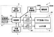
- FIG. 2 is a block diagram of the head-up display device of FIG.
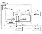
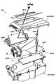
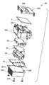
- FIG. 3 is a diagram showing a power supply circuit of the head-up display device of FIG. 4 is an exploded perspective view of a display output unit of the head-up display device of FIG.
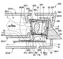
- FIG. 5 is a partially enlarged cross-sectional view of a display output unit of the head-up display device of FIG.
- FIG. 6 is a schematic diagram illustrating a configuration of a display unit of the head-up display device of FIG. FIG.
- FIG. 7 is an exploded perspective view of the main body of the head-up display device of FIG.
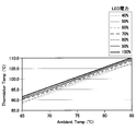
- FIG. 8 is a diagram illustrating a correspondence relationship between the drive current of the light source and the detected temperature of the temperature detection unit in the head-up display device of FIG.
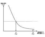
- FIG. 9 is a diagram illustrating a correspondence relationship between the display responsiveness of the display unit and the temperature of the display unit (or the detected temperature of the temperature detection unit) in the head-up display device of FIG.
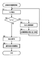
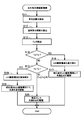
- FIG. 10 is a flowchart showing a flow of light source drive control performed when the engine of the vehicle is started in the head-up display device of FIG.
- FIG. 11 is a flowchart showing a flow of light source drive control that is performed in the normal time after the engine of the vehicle is started in the head-up display device of FIG.
- the head-up display device 1 projects display information emitted from the display output unit 200 to the projection member 100W and reflects the projected display information toward a user 100D at a predetermined position. By doing so, the user 100D is configured to visually recognize the reflected image.
- the head-up display device 1 of the present embodiment is a vehicle head-up display device, and a user 100D at a predetermined position for visually recognizing display information is a driver seated in a driver's seat.
- the projection member 100W is a member that transmits light, and here is a windshield (front glass) 100W that is inclined with respect to the horizontal direction of the vehicle 100. *
- the display output unit 200 includes a display unit 2 that forms display information, and a light source 3 that illuminates the display unit 2 and emits display information to the outside. 20.
- the display output unit 200 of the present embodiment is provided inside an instrument panel 100 ⁇ / b> I that extends from the lower side of the windshield 100 ⁇ / b> W to the inside of the vehicle 100.
- the display unit 2 in the present embodiment is a transmissive display panel that is illuminated by light from the light source 3 on the back side, and the light of the light source 3 that has passed through the display panel 2 is directed toward the upper windshield 100W. Incident.
- the light incident on the windshield 100W is reflected toward the user 100D seated in the driver's seat, and the user 100D visually recognizes the reflected image.
- the display information projected and reflected on the windshield 100W is captured by the driver 100D as a virtual image 2V positioned at the tip (back) of the windshield 100W. That is, the driver 100D sees the display information at the tip (back) of the windshield 100W by forming the display information formed by the display panel 2 on the front side outside the windshield 100W.
- the display unit 2 of this embodiment is a TFT liquid crystal panel.
- the TFT liquid crystal panel 2 is well known, and as shown in FIG. 6, the liquid crystal layer 2A is sealed between the glass substrates 2B and 2F, and further, they are sandwiched between the polarizing plates 2G and 2E from the outside. Formed in shape.
- the liquid crystal panel 2 has a plurality of liquid crystal cells arranged in a matrix. Each liquid crystal cell can be individually applied with a voltage by a switch element and a pixel electrode forming a TFT (Thin Transistor) provided therein.
- TFT Thin Transistor
- the liquid crystal panel 2 changes the alignment direction of the liquid crystal molecules in the pixel region of each liquid crystal cell by applying a voltage to each of the liquid crystal cells, thereby enabling gradation display in each pixel region.
- the liquid crystal panel 2 can also change the alignment direction of the liquid crystal molecules of all the liquid crystal cells so that the light from the light source 3 is not transmitted.
- the liquid crystal panel 2 has a problem that the display responsiveness falls below a certain level in a low temperature state below a predetermined temperature.
- the head-up display device 1 of the present disclosure in order to eliminate the low temperature state, no heaters are arranged, and heat generated by light emission of the light source 3 is transmitted to the display unit via the gas in the space 22H.
- the display unit 2 is configured to be warmed.
- the head-up display device 1 faces both the display unit 2 and the light source 3 and transmits the heat on the light source 3 side to the display unit 2 (heat transfer space).
- the housing part 22 forming 22H, the temperature detection part 5 for detecting the ambient temperature Ts of the display part 2 and the light source 3 as shown in FIGS. 2 and 3, and a reference low temperature whose ambient temperature Ts is predetermined.
- a control unit (first light source control means) 10 that performs light source control for increasing the luminance by increasing the drive current for causing the light source 3 to emit light when Ta falls below Ta.
- the temperature of the display unit 2 can be increased by intentionally increasing the drive current energized to cause the light source 3 to emit light. That is, when the drive current of the light source 3 increases, the heat generation of the light source 3 and its drive circuit 3D also increases, so the temperature (air temperature) of the internal space 22H in contact with these light source 3 and drive circuit 3D also rises, while the internal space Since 22H also contacts the display unit 2, when the temperature (air temperature) of the internal space 22H increases, the temperature of the display unit 2 also increases due to the heat (temperature increase).
- the control unit 10 also performs light source control to reduce the luminance by reducing the drive current that causes the light source 3 to emit light even when the detection temperature Ts of the temperature detection unit 5 exceeds a predetermined reference high temperature Tb ( Second light source control means), the temperature of the display unit 2 is lowered by the decrease of the drive current.
- the drive current of the light source 3 decreases, the heat generation of the light source 3 and its drive circuit 3D also decreases, so the temperature (air temperature) of the internal space (heat transfer space) 22H in contact with the light source 3 and the drive circuit 3D also decreases.
- the internal space 22H is also in contact with the display unit 2, when the temperature (air temperature) of the internal space 22H decreases, the temperature of the display unit 2 also decreases due to the heat (temperature decrease).
- control unit 10 is an MPU (Micro-Processing Unit) connected to the display panel 2 and the light source 3 via each drive circuit (driver) 2D, 3D.
- the control unit 10 of the present embodiment includes an IG switch (ignition switch) 4, a temperature detection unit 5 that detects the ambient temperature of the display unit 2, and a light amount detection unit (illuminance sensor) 7 that detects a light amount (illuminance) outside the vehicle. And a storage unit 9 for storing various reference values Ta, Tb and the like. *
- the temperature detection unit 5 is provided around the display unit 2 and detects the temperature of the peripheral unit 21, and can be a known thermistor or the like. That is, the temperature detection unit 5 of the present embodiment does not directly detect the temperature of the display unit 2 but detects the temperature at another position that changes due to the temperature change of the display unit 2. *
- the control part 10 acquires the detection information of the temperature detection part 5, and detects the ambient temperature Ts of the display part 2 (S1: temperature detection means). When the detected temperature Ts falls below a predetermined reference low temperature Ta (S2: Yes), control is performed such that the light from the light source 3 is invisible to the user (S3: visual state control). means).
- the control unit 10 outputs an alignment change command to the drive circuit 2D so that all the liquid crystal cells of the liquid crystal panel forming the display unit 2 have a liquid crystal alignment in which light from the light source 3 is not transmitted.
- control unit 10 outputs a change command for increasing the drive current of the light source 3 to a maximum current value that is maximum within a predetermined use range used during energization (S4).
- S4 a predetermined use range used during energization
- the control unit 10 performs control such that the light from the light source 3 is visible to the user (S5: Visual state control means).
- the control unit 10 cancels the alignment change command output to the drive circuit 2D so that all the liquid crystal cells of the liquid crystal panel forming the display unit 2 have a liquid crystal alignment in which light from the light source 3 is not transmitted.
- An arbitrary liquid crystal alignment change is permitted (S5: visual state control means).
- the control unit 10 starts normal light source drive control as shown in FIG. 11 (S6) and ends the control of FIG. *
- the control unit 10 causes the light source 3 to emit light with the maximum luminance within the usable range of the drive current, thereby causing the light source 3 and its drive circuit 3D to generate heat, and the temperature of the liquid crystal panel 2 with the heat. Can be raised.
- the drive circuit 2D of the liquid crystal panel 2 receives display data from the external display control unit 2000 (see FIG.
- control is performed in the form of energization control to the liquid crystal cell, as long as it is determined that the temperature of the liquid crystal panel 2 is in a temperature range in which the display responsiveness is not guaranteed in the process of FIG.
- the energization control to each liquid crystal cell based on the received data is forcibly prohibited, and the energization control is performed with priority given to the liquid crystal alignment in which all the liquid crystal cells do not transmit light.
- the control unit 10 starts energization control to each liquid crystal cell based on the received data, and according to the situation.
- the displayed information is projected onto the windshield 100W so that the driver can visually recognize it. *
- control unit 10 that has started the light source drive control in FIG. 11 first detects the amount of light outside the vehicle 100 from the light amount detection unit 7 (S11), and based on the detected amount of light outside the vehicle, The drive current of the light source 3 is calculated (S12). *
- the control unit 10 of the present embodiment keeps the drive current of the light source 3 at a predetermined value determined by the display content, and exceeds the predetermined light amount. If not, the driving current of the light source 3 is reduced from the predetermined value by a predetermined level (for example, 50% or less of the predetermined value (specifically 40% or the like)).
- the controller 10 may increase the luminance as the detected light amount of the light amount detector 7 increases, and decrease the luminance as the detected light amount of the light amount detector 7 decreases.
- control unit 10 detects the ambient temperature Ts of the display unit 2 from the temperature detection unit 5 (S13), and when the detected ambient temperature Ts exceeds a predetermined reference high temperature Tb (S14: Yes), the already calculated driving current value of the light source 3 is corrected and set so as to decrease (S16), and the light source 3 is caused to emit light with the corrected driving current value (S17).
- the control unit 10 determines the drive current value of the light source 3 that has already been calculated. The value is corrected and set to increase (S18), and the light source is caused to emit light with the corrected drive current value (S19). *
- the control unit 10 when the detected ambient temperature Ts is equal to or lower than the reference high temperature Tb and equal to or higher than the reference low temperature Ta (S14: No and S15: No), the control unit 10 already calculates the drive current value.
- the light source 3 is caused to emit light (calculated value in S12) (S20).
- the process of FIG. 11 is repeatedly executed at a predetermined cycle. *
- the corrected drive current value is calculated with a constant increase or decrease with respect to the drive current value calculated before the correction (the calculated value in S12).
- the control unit 10 can be configured to make a correction to increase or decrease the drive current value (S12) uniformly (for example, 20%). Note that other methods may be employed for calculating the corrected drive current value.
- the reference low temperature Ta and the reference high temperature Tb are values determined based on the guaranteed operating temperature that ensures the operation of the display unit 2 including the display response. Specifically, each of the reference low temperature Ta and the reference high temperature Tb receives a temperature range in which the operation of the display unit 2 is ensured, and is a lower limit of the operating temperature range of the display unit 2 that is narrower than the temperature range. It is a value determined based on the value a and the upper limit value b.
- the reference high temperature Ta of the present embodiment is the temperature detected by the temperature detection unit 5 when the temperature of the display unit 2 is the lower limit value a of the guaranteed operating temperature range, and the reference high temperature Tb is the operation of the temperature of the display unit 2 It is determined as the detected temperature of the temperature detector 5 when the temperature range is the upper limit b.
- the temperature detection unit 5 of the present embodiment detects the temperature affected by both the temperature of the light source 3 and its drive circuit 3D and the temperature of the display unit 2, and therefore the detected temperature is This is a value reflecting the current temperature of the display unit 2 or a temperature slightly ahead. That the detected temperature of the temperature detecting unit 5 is lower than the reference high temperature Ta indicates that the temperature of the display unit 2 may be lower than the guaranteed operating temperature range after this, while the detected temperature of the temperature detecting unit 5 is Exceeding the reference high temperature Tb indicates that the temperature of the display unit 2 may possibly exceed the operation guarantee temperature range thereafter. According to the light source drive control of FIG.
- the temperature detection unit 5 is disposed at a position where a proportional relationship is established in actual measurement between the drive current of the light source 3 and the detected temperature of the temperature detection unit 5. Thereby, a correlation is provided between the driving current of the light source 3 and the temperature of the display unit 2.
- the fact that the drive current of the light source 3 and the detected temperature of the temperature detection unit 5 have a proportional relationship in actual measurement means that the temperature in the atmosphere outside the head-up display device 1 (here, the temperature outside the vehicle or the temperature at a predetermined position in the vehicle) is constant.
- the drive current of the light source 3 is energized at a constant value, and the constant value of the energized drive current and the saturation value of the detected temperature of the temperature detection unit 5 detected at the time of energization are constant.
- the saturation value follows a proportional relationship as shown in FIG.
- the temperature of the display unit 2 also affects the temperature detected by the temperature detection unit 5, and the fact that the saturation value of the detection temperature of the temperature detection unit 5 has been determined means that the temperature of the display unit 2 at that time is saturated.
- the value is also determined. Thereby, the correlation between the drive current of the light source 3 and the temperature of the display unit 2 is obtained. Actually, there is an error of the level shown in FIG. 8, but even if there is an error of this level, it is assumed that the proportional relationship is established. *
- the relationship that follows proportionally as described above continues.
- the temperature outside the head-up display device 1 is in a temperature range close to the actual use environment, but a predetermined temperature in the vicinity of the other use environment. The same relationship exists in the range.
- the display output unit 200 includes a case (apparatus housing) 201 that houses the main body 20 together with the main body 20.
- the case 201 includes a first side case portion (upper case) 201A that forms the first side (here, the upper side of the vehicle 100) and a second side opposite to the first side (here, the lower side of the vehicle 100). ) Forming a second side case portion (lower case) 201B.
- first side case portion upper case
- second side opposite to the first side here, the lower side of the vehicle 100.
- the optical member 202B of the present embodiment is a plane mirror, and the optical member 202A is a magnifying mirror that magnifies and reflects incident light.
- the display information emitted from the display output unit 200 is magnified by the magnifying glass 202A and projected onto the windshield 100W.
- the magnifying glass 202A can change the reflection direction by the drive unit (motor) 202M.
- the projection position on the windshield 100W can be changed by changing the reflection direction.
- the optical members 202A and 202B are not necessarily limited to the configuration of the present embodiment, and it is possible to appropriately change the shape, replace the members, change the arrangement, and the like. *
- the case 201 of the present embodiment includes a main body housing portion 201 ⁇ / b> H that houses the main body portion 20, and an optical system housing portion 201 ⁇ / b> I that houses optical members 202 ⁇ / b> A and 202 ⁇ / b> B (see FIG. 4). And a main control board housing portion 201J for housing a main control board 11 on which a main control portion 10 described later is formed.
- the accommodating portions 201 ⁇ / b> H, 201 ⁇ / b> I, and 201 ⁇ / b> J are partitioned by an inner case portion (inner case) 201 ⁇ / b> C disposed in the case 201.
- the inner case part (inner case) 201C is arranged as a partition wall part 201G that partitions the optical system accommodation part 201I and the main control board accommodation part 201J.
- the wall 201G is interrupted on one end side (the right side in FIG. 5).
- the main control board housing portion 201J and the optical system housing portion 201I communicate with each other through the disconnected opening 201K.
- the inner case portion (inner case) 201C includes a fixing portion 201D (see FIG. 4) that fixes the main body portion 20 at a point where the wall portion 201G is interrupted.
- the main body portion 20 is fixed to the fixing portion 201D and disposed on the optical system housing portion 201I side of the opening 201K.
- the main body housing portion 201H forms a space on the optical system housing portion 201I side of the opening 201K in which the main body portion 20 is housed.
- the optical system housing part 201I is formed as a space adjacent to the main body housing part 201H, and is adjacent to the main control board housing part 201J with the wall part 201G interposed therebetween.
- the main body housing portion 201H and the optical system housing portion 201I are configured such that the wall portion 201W extending so as to approach each other on both the first side case portion 201A and the inner case portion 201C has an opening 201L therebetween.
- the main body accommodating portion 201H and the optical system accommodating portion 201I are partitioned.
- the main control board housing portion 201J includes a space on the main control board housing portion 201J side of the fixed portion 201D and is adjacent to both the main body housing portion 201H and the optical system housing portion 201I.
- the case 201 of the present embodiment is formed such that when mounted on the vehicle 100, the main body housing portion 201H and the optical system housing portion 201I are adjacent to each other in the horizontal direction on the upper side, and the main control board housing portion 201J 201H is formed adjacent to the lower side of the optical system accommodating portion 201I.
- the first side case portion 201A is the vehicle 100 in the case 201.
- the second case part 201B is located on the lower side of the vehicle 100 in the case 201, and the inner case part 201C is located between the first and second case parts 201A and 201B.
- the main body housing portion 201H and the optical system housing portion 201I are formed on the first side case portion 201A side with respect to the inner case portion 201C, and the main control board housing portion 201J is formed on the second side case portion 201B side.
- a vent hole 2H1 that communicates with the outside (device outer space) 20H is provided on the upper side of the vehicle 100 of the case 201. Further, a vent hole 2H2 that communicates with the outside (outside apparatus space) 20H is also provided on the lower side of the vehicle 100 of the case 201. Thereby, the heat in the case 201 can be efficiently discharged.
- the vent hole 2H1 of the present embodiment is formed as a through hole penetrating upward of the vehicle 100 in the first side case portion 201A, and the vent hole 2H2 is formed below the vehicle 100 in the second side case portion 201B. It is formed as a through-hole penetrating toward.
- the main body unit 20 arranges the display unit 2 and the light source 3 with a space (heat transfer space) 22H interposed therebetween, and the display unit 2 and the light source 3 form a main body. It is housed in the case 22.
- the main body case 22 of the present embodiment includes a cylindrical portion 22A that surrounds the axis line from the light source 3 toward the display portion 2, and the display portion 2 side of the cylindrical portion 22A.
- a lid portion (case lid) 22B that is assembled and fixed to the opening, and a heat radiating portion 22F that is assembled and fixed to the opening on the light source 3 side of the cylindrical portion 22A.
- an internal space 22 ⁇ / b> H partitioned from the outside of the main body 20 is formed in the main body 20.
- well-known lens members 23 and 25 and well-known light are used as optical members for condensing the light of the light source 3 into the internal space 22H so as to enter the back surface 2B of the display unit 2 widely and uniformly.
- a diffusion sheet 24 is disposed.
- two lens members 23 and 25 and one light diffusion sheet 24 are used.
- the lens member 23 is a diffusing lens
- the lens member 25 is a condenser lens.
- the circuit board 31 on which the light source 3 is mounted is disposed on the inner main surface 22FA (see FIG. 7) facing the internal space 22H.
- the heat radiation part 22F and the circuit board 31 are fixed by the screw member 22N (see FIG. 7).
- the circuit board 31 here is an aluminum board with high heat dissipation.
- fins 22G are formed on the outer side opposite to the main surface 22FA side of the heat radiation part 22F for heat radiation, and the fins 22G are arranged so as to penetrate the case 201 of the display output part 200 from the inner side toward the outer side.
- the lid 22B has a light emission hole 22J at the center thereof, and emits the light of the light source 3 that has passed through the display panel 2 from the light emission hole 22J to the outside.
- the cylindrical portion 22A is provided with an assembly portion 22C extending toward the peripheral edge portion 22E of the light emission hole 22J at the center of the lid portion 22B.
- the display portion 2 includes the assembly portion 22C and the lid portion 22B. It is assembled
- the main body case 22 is a light source housing portion that houses the light source 3 in the internal space 22H.
- the light source 3 and the mounting surface 31A of the circuit board 31 on which the light source 3 is mounted are exposed in the internal space 22H. It is arranged with. Light from the light source 3 is emitted from the inside of the main body case 22 to the outside through the optical members 23 to 25 and the display unit 2 covering the light emission holes 22J. *
- the main control board 11 here has a power supply circuit connected to the in-vehicle battery 100 ⁇ / b> B, and an MPU (Micro-Processing Unit) that is a control unit 10 that controls the power supply system of the head-up display device 1. ) Is implemented.
- a voltage of about 12V (battery voltage + B) of the in-vehicle battery 100B is input to the control unit 10 of FIG. 2 as a power supply voltage of 5V via the DC / DC converter 12, while 3V via the DC / DC converter 13. .3V is input to the display unit 2 as a power supply voltage.
- the 3.3V power supply line input to the display unit 2 is provided with a thermistor forming the temperature detection unit 5 for reducing the inrush current, and the control unit 10 monitors a resistance value change associated with the temperature change.
- the drive circuit 3D of the light source 3 is provided on another circuit board 31, but the power supply voltage (battery voltage) of the in-vehicle battery 100B input to the drive circuit 3D is also on the main control board 11. Is input via the power supply circuit. *
- the drive circuit 2D of the display unit 2 is also provided on the main control board 11.
- the drive circuit 2D may be provided as a separate substrate from the main control substrate 11.
- the main control board 11 of the present embodiment connects the connector parts 11C, 2C, 31C to the display part 2 and the circuit board 31 via wiring members such as lead wires 2L, 3L. *
- the temperature detection unit 5 is disposed outside the main body unit 20.
- the temperature detection unit 5 according to the present embodiment is provided in an adjacent space 201J (21H) adjacent to an internal space 22H of a main body case (light source storage unit) 22 that stores the light source 3 via a cylindrical portion 22A (wall portion 22D). Is provided.
- the inside of the main control board housing portion 201J corresponds to the adjacent space 201J.
- the temperature detection unit 5 of the present embodiment is mounted on a main control board 11 that is different from the circuit board 31 on which the light source 3 is mounted and the drive circuit 3D of the light source 3 is formed.
- the internal space 22H of the main body case 22 has a vent hole 20L that communicates with the main body housing portion 201H that is the outside thereof, and as a result, also communicates with the main control board housing portion 201J.
- the heat generated in 31 is transmitted to the temperature detection unit 5 through the internal space 22H of the main body unit 20, the internal space of the main body housing unit 201H, and the internal space of the main control board housing unit 201J.
- the heat generated in the light source 3 and its mounting substrate 31 is not directly transmitted to the temperature detection unit 5 and detected, but is transmitted and detected through a space (gas). Since it is transmitted through the partitioned space and detected, even if the temperature change of the light source 3 and its mounting board 31 occurs severely, the change is not detected directly, but is detected in an appropriately averaged form. Is done. *
- the temperature detection unit 5 of the present embodiment is disposed at a position immediately below a position (here, an intermediate position) between the display unit 2 and the light source 3 that are disposed to face each other in the horizontal direction of the vehicle 100. Thereby, it is possible to detect a temperature in which both the temperature of the display unit 2 and the temperatures of the light source 3 and the circuit board 31 are reflected in a balanced manner.
- the temperature detection unit 5 of the present embodiment is disposed on the main surface 11B of the main control board 11 on the main body 20 side at a position directly below the main body 20.
- the temperature detection unit 5 of the present embodiment is on the ventilation hole 2H2 provided in the bottom wall part 201F of the second side case part 201B forming the main control board housing part 201J or on the peripheral part of the ventilation hole 2H2. Has been placed. *
- a general head-up display device projects light from a light source onto a projection member located at a distant position so that the reflected image can be seen, so that the light source emits light with higher brightness than other display devices. It is necessary to let For this reason, more heat is generated during light emission than other display devices. In the present disclosure, this heat is effectively used as heat for heating the display unit, and the display response performance is obtained by warming the display unit in a low temperature state where the display response performance is not secured by the heat generated during light source emission. Therefore, it is not necessary to provide a dedicated heater for heating the display unit, its control circuit, or the like as in the conventional case.
- the temperature detection unit does not directly detect the temperature of the display unit, but detects the ambient temperature of both the display unit and the light source.
- the temperature detection unit detects a temperature in which the influences of both the display unit and the light source are taken into account. From this ambient temperature, it is possible not only to estimate the current temperature of the display unit, but also to estimate future temperature changes of the display unit from changes in this ambient temperature. It is possible to perform light emission control of the light source 3 so that the temperature of the light source is continuously equal to or higher than the reference low temperature.
- the head-up display device reduces the luminance by reducing the drive current that causes the light source to emit light when the temperature detected by the temperature detection unit exceeds a predetermined reference high temperature.
- the temperature of the heat transfer space can be lowered by reducing the heat generation due to the reduction of the drive current, and the temperature drop can be transmitted to the display unit to lower the temperature of the display unit. According to this configuration, even when the display unit is excessively heated, the display unit can be cooled and used by reducing the light emission level of the light source.
- the display unit 2 in the above embodiment is a TFT liquid crystal panel, but another one may be adopted as long as it has a problem in display response as in the above embodiment. *
- the light from the light source 3 is projected onto the projection member 100W in order to control the light from the light source 3 to be invisible to the user (S3: visual state control means).
- the liquid crystal panel 2 that is a light transmittance variable portion that can change the light transmittance is used, but other methods may be used.
- a light transmission variable unit viewing state switching unit
- the control unit 10 controls this. May be.
- the path changing unit may be the driving unit (motor) 202M, and the driving unit 202M is driven and controlled by the display control unit 2000 according to a command from the control unit 10.
- the light source drive control of both FIGS. 10 and 11 is performed, but only one of them may be performed.
- only the processing (S14, S16, S17) on the side of reducing the drive current of the light source 3 by correction may be performed, and conversely, the drive current of the light source 3 can be corrected.
- Only the processing on the increasing side (S15, S18, S19) may be performed.
- the temperature detection unit 5 is provided at a position having a proportional relationship as a predetermined correspondence between its own detection temperature Ts and the drive current of the light source 3.
- the detected temperature Ts may be a position corresponding to another correspondence relationship in which the detected temperature Ts increases as the driving current of the light source 3 increases.
- this correspondence is determined based on actual measurement, and is determined by the saturation value of the temperature of the temperature detection unit 5 as in the above embodiment.
- each means is expressed as, for example, S1.
- each means can be divided into a plurality of sub means, while a plurality of means can be combined into one means.
- each means configured in this way can be referred to as a module, means.
Abstract
This vehicular heads-up display device, in which display information formed by a display unit (2) is projected onto and reflected off of an external projection member (100W) via light from a light source (3) such that a user (100D) at a prescribed position can see the resulting reflected image, is provided with a containing part (22), a temperature detection unit (5), and a light-source control means (S1 through S6 and S11 through S20). The containing part contains the display unit (2) and the light source (3). The display unit and the light source are laid out so as to face each other with a heat-transfer space (22H) inside the containing part interposed therebetween. The temperature detection unit is provided in a surrounding section (21) surrounding the display unit and the light source and detects the temperature of said surrounding section. If the temperature detected (Ts) by the temperature detection unit falls below a predetermined low-temperature threshold (Ta), the light-source control means controls the light source so as to increase the brightness thereof by increasing a driving current that is making the light source emit light. The heat produced as said driving current is increased is transferred to the display unit via the heat-transfer space, at least, and raises the temperature of the display unit.
Description
本開示は、2013年8月1日に出願された日本出願番号2013-160547号に基づくもので、ここにその記載内容を援用する。
This disclosure is based on Japanese Patent Application No. 2013-160547 filed on August 1, 2013, the contents of which are incorporated herein.
本開示は、ヘッドアップディスプレイ装置に関する。
The present disclosure relates to a head-up display device.
例えば車両のインストルメントパネルにあるメータ等の画像をウインドシールドに表示する表示装置として、ヘッドアップディスプレイ(HUD:Head-Up Display)装置が知られている(特許文献1)。ヘッドアップディスプレイ装置は、メータ等の表示情報を、ウインドシールドに投射して反射させ、その反射像を運転者に視認させる。ウインドシールドに投射された表示情報は、ウインドシールドの車外前方側で像が結像し、運転者は前方視界に重畳される形で、表示情報を視認することができる。こうしたヘッドアップディスプレイにおいて運転者に視認させる表示情報を形成する装置は、一般的には液晶表示装置である。液晶表示装置には、例えば垂直配光型のTFT(Thin Film Transistor)液晶表示装置や単純マトリックス型の液晶表示装置等がある。
For example, a head-up display (HUD) device is known as a display device that displays an image of a meter or the like on a vehicle instrument panel on a windshield (Patent Document 1). The head-up display device projects display information such as a meter onto a windshield and reflects it, and causes the driver to visually recognize the reflected image. The display information projected on the windshield forms an image on the front side outside the vehicle of the windshield, and the driver can visually recognize the display information in a form superimposed on the front field of view. A device for forming display information to be visually recognized by the driver in such a head-up display is generally a liquid crystal display device. Examples of the liquid crystal display device include a vertical light distribution type TFT (Thin Film Transistor) liquid crystal display device and a simple matrix type liquid crystal display device. *
しかしながら、こうした液晶表示装置では、低温時において表示応答速度が遅いため、表示器にITO(Indium Tin Oxide)ヒータやサーミスタを設け、そのヒータによって、表示応答速度が一定レベル以上確保できる温度まで温めた上で、表示を行う必要がある。ところが、ITOヒータは、液晶パネルのガラス上に生成される半透明膜であるから、液晶パネルを照明する光源からの光の透過量を減じる要因になり、表示輝度を下げてしまうという課題がある。さらにいえば、ITOヒータやサーミスタ、さらにそれらの制御回路を設けることは、装置及び回路の複雑化を招くだけでなく、コストアップの要因にもなる。特にITOヒータを設ける場合には、故障による暴走防止のために別の制御回路も必要となるため、回路構成はより複雑化し、より一層のコストアップを避けることができない。
However, in such a liquid crystal display device, since the display response speed is low at low temperatures, an ITO (Indium Tin Oxide) heater or thermistor is provided in the display, and the heater is heated to a temperature at which a display response speed can be secured above a certain level. Above, we need to make a display. However, since the ITO heater is a semi-transparent film formed on the glass of the liquid crystal panel, it causes a reduction in the amount of light transmitted from the light source that illuminates the liquid crystal panel, and there is a problem that the display luminance is lowered. . Furthermore, providing an ITO heater, a thermistor, and a control circuit therefor not only complicates the apparatus and the circuit but also increases the cost. In particular, when an ITO heater is provided, another control circuit is required to prevent runaway due to a failure, so that the circuit configuration becomes more complicated and further cost increase cannot be avoided.
本開示は、上記点に鑑みてなされたものであり、その目的は、低温時に表示応答性能が悪化する表示部と、これを照明する光源とを備えたヘッドアップディスプレイ装置において、コスト増を抑えて低温時の表示応答性能の悪化を解決できるヘッドアップディスプレイ装置を提供することにある。
The present disclosure has been made in view of the above points, and an object thereof is to suppress an increase in cost in a head-up display device including a display unit whose display response performance deteriorates at a low temperature and a light source that illuminates the display unit. Another object of the present invention is to provide a head-up display device that can solve the deterioration in display response performance at low temperatures. *
本開示の一態様によるヘッドアップディスプレイ装置は、表示部が形成する表示情報を、光源の光により外部の投影部材に投影して反射させ、その反射像を所定位置のユーザーに視認させる車両用ヘッドアップディスプレイ装置であって、表示部と光源を収容する収容部と、温度検出部と、光源制御手段とを備える。表示部と光源は、収容部の内部の伝熱空間を介して面する形で配置されている。温度検出部は、表示部と光源の周辺部に設けられ、その周辺部の温度を検出する。光源制御手段は、温度検出部の検出温度が予め定められた基準低温度を下回った場合に、光源を発光させる駆動電流を増して輝度を上げるよう制御して、その駆動電流の増加に伴い発生する熱を、少なくとも伝熱空間を介して表示部に伝達して表示部を温度上昇させる。
A head-up display device according to an aspect of the present disclosure is a vehicle head that causes display information formed by a display unit to be projected and reflected on an external projection member by light of a light source, and allows a user at a predetermined position to visually recognize the reflected image. An up-display device, comprising a display unit, a storage unit for storing a light source, a temperature detection unit, and a light source control means. The display unit and the light source are arranged so as to face each other through a heat transfer space inside the housing unit. The temperature detection unit is provided in the periphery of the display unit and the light source, and detects the temperature of the periphery. When the temperature detected by the temperature detection unit falls below a predetermined reference low temperature, the light source control means controls to increase the brightness by increasing the drive current that causes the light source to emit light, and occurs as the drive current increases The heat to be transmitted is transmitted to the display unit through at least the heat transfer space to raise the temperature of the display unit. *
上記ヘッドアップディスプレイ装置によると、低温時に表示応答性能が悪化する表示部と、これを照明する光源とを備えたヘッドアップディスプレイ装置において、コスト増を抑えて低温時の表示応答性能の悪化を解決できる。
According to the above head-up display device, in a head-up display device having a display unit whose display response performance deteriorates at low temperatures and a light source that illuminates the display unit, the deterioration in display response performance at low temperatures is suppressed while suppressing an increase in cost. it can.
本開示についての上記目的およびその他の目的、特徴や利点は、添付の図面を参照しながら下記の詳細な記述により、より明確になる。その図面は、
図1は、本開示の一実施形態によるヘッドアップディスプレイ装置の構成を示した概略図であり、
図2は、図1のヘッドアップディスプレイ装置のブロック図であり、
図3は、図1のヘッドアップディスプレイ装置の電源回路を示す図であり、
図4は、図1のヘッドアップディスプレイ装置の表示出力部の分解斜視図であり、
図5は、図1のヘッドアップディスプレイ装置の表示出力部の部分拡大断面図であり、
図6は、図1のヘッドアップディスプレイ装置の表示部の構成を示した概略図であり、
図7は、図1のヘッドアップディスプレイ装置の本体部の分解斜視図であり、
図8は、図1のヘッドアップディスプレイ装置における光源の駆動電流と温度検出部の検出温度との間の対応関係を示す図であり、
図9は、図1のヘッドアップディスプレイ装置における表示部の表示応答性と、表示部の温度(あるいは温度検出部の検出温度)との間の対応関係を示す図であり、
図10は、図1のヘッドアップディスプレイ装置において車両のエンジン始動時に実施される光源駆動制御の流れを示すフローチャートであり、
図11は、図1のヘッドアップディスプレイ装置において車両のエンジン始動後の通常時に実施される光源駆動制御の流れを示すフローチャートである。
The above and other objects, features and advantages of the present disclosure will become more apparent from the following detailed description with reference to the accompanying drawings. The drawing
FIG. 1 is a schematic diagram illustrating a configuration of a head-up display device according to an embodiment of the present disclosure. FIG. 2 is a block diagram of the head-up display device of FIG. FIG. 3 is a diagram showing a power supply circuit of the head-up display device of FIG. 4 is an exploded perspective view of a display output unit of the head-up display device of FIG. FIG. 5 is a partially enlarged cross-sectional view of a display output unit of the head-up display device of FIG. FIG. 6 is a schematic diagram illustrating a configuration of a display unit of the head-up display device of FIG. FIG. 7 is an exploded perspective view of the main body of the head-up display device of FIG. FIG. 8 is a diagram illustrating a correspondence relationship between the drive current of the light source and the detected temperature of the temperature detection unit in the head-up display device of FIG. FIG. 9 is a diagram illustrating a correspondence relationship between the display responsiveness of the display unit and the temperature of the display unit (or the detected temperature of the temperature detection unit) in the head-up display device of FIG. FIG. 10 is a flowchart showing a flow of light source drive control performed when the engine of the vehicle is started in the head-up display device of FIG. FIG. 11 is a flowchart showing a flow of light source drive control that is performed in the normal time after the engine of the vehicle is started in the head-up display device of FIG.
本開示のヘッドアップディスプレイ装置の一実施形態を、図面を用いて説明する。
An embodiment of a head-up display device of the present disclosure will be described with reference to the drawings. *
図1に示すように、ヘッドアップディスプレイ装置1は、表示出力部200から外部に出射された表示情報を投影部材100Wに投影して、投影された表示情報を所定位置のユーザー100Dに向けて反射させることにより、ユーザー100Dに、その反射像を視認させるよう構成される。本実施形態のヘッドアップディスプレイ装置1は車両用のヘッドアップディスプレイ装置であり、表示情報を視認する所定位置のユーザー100Dは運転席に着座した運転者である。また、投影部材100Wは光を透過する部材であり、ここでは車両100の水平方向に対し傾斜配置されるウインドシールド(フロントガラス)100Wとされている。
As shown in FIG. 1, the head-up display device 1 projects display information emitted from the display output unit 200 to the projection member 100W and reflects the projected display information toward a user 100D at a predetermined position. By doing so, the user 100D is configured to visually recognize the reflected image. The head-up display device 1 of the present embodiment is a vehicle head-up display device, and a user 100D at a predetermined position for visually recognizing display information is a driver seated in a driver's seat. Further, the projection member 100W is a member that transmits light, and here is a windshield (front glass) 100W that is inclined with respect to the horizontal direction of the vehicle 100. *
表示出力部200は、図5及び図7に示すように、表示情報を形成する表示部2と、その表示部2を照明して表示情報を外部に出射する光源3と、を有した本体部20を備える。本実施形態の表示出力部200は、図1に示すように、ウインドシールド100Wの下側から車両100の内側へ延出するインストルメントパネル100Iの内部に設けられる。また、本実施形態における表示部2は、背面側の光源3からの光によって照明される透過型の表示パネルであり、表示パネル2を透過した光源3の光は上方のウインドシールド100Wに向けて入射する。ウインドシールド100Wに入射した光は、運転席に着座したユーザー100Dに向けて反射し、ユーザー100Dはその反射像を視認する。なお、ウインドシールド100Wに投影されて反射した表示情報は、ウインドシールド100Wの先(奥)に位置する虚像2Vとして、運転者100Dに捕らえられる。つまり、表示パネル2が形成する表示情報をウインドシールド100Wの外側前方で結像させることで、運転者100Dは、ウインドシールド100Wの先(奥)に表示情報を見ることになる。
As shown in FIGS. 5 and 7, the display output unit 200 includes a display unit 2 that forms display information, and a light source 3 that illuminates the display unit 2 and emits display information to the outside. 20. As shown in FIG. 1, the display output unit 200 of the present embodiment is provided inside an instrument panel 100 </ b> I that extends from the lower side of the windshield 100 </ b> W to the inside of the vehicle 100. The display unit 2 in the present embodiment is a transmissive display panel that is illuminated by light from the light source 3 on the back side, and the light of the light source 3 that has passed through the display panel 2 is directed toward the upper windshield 100W. Incident. The light incident on the windshield 100W is reflected toward the user 100D seated in the driver's seat, and the user 100D visually recognizes the reflected image. The display information projected and reflected on the windshield 100W is captured by the driver 100D as a virtual image 2V positioned at the tip (back) of the windshield 100W. That is, the driver 100D sees the display information at the tip (back) of the windshield 100W by forming the display information formed by the display panel 2 on the front side outside the windshield 100W. *
本実施形態の表示部2はTFT液晶パネルである。TFT液晶パネル2は周知のものであり、図6に示すように、液晶層2Aがガラス基板2B、2Fに挟まれる形で封止され、さらにそれらが外側から偏光板2G、2Eで挟まれた形で形成される。液晶パネル2は、マトリクス状に配列された複数の液晶セルを有する。各液晶セルは、それぞれに設けられたTFT(Thin Film Transistor)をなすスイッチ素子及び画素電極によって、個別に電圧印加可能である。液晶パネル2は、これら各液晶セルへの電圧印可により、各液晶セルの画素領域における液晶分子の配向方向を変化させ、各画素領域での階調表示を可能としている。当然、液晶パネル2は、光源3からの光が透過しないように、全液晶セルの液晶分子の配向方向を変化させることもできる。
The display unit 2 of this embodiment is a TFT liquid crystal panel. The TFT liquid crystal panel 2 is well known, and as shown in FIG. 6, the liquid crystal layer 2A is sealed between the glass substrates 2B and 2F, and further, they are sandwiched between the polarizing plates 2G and 2E from the outside. Formed in shape. The liquid crystal panel 2 has a plurality of liquid crystal cells arranged in a matrix. Each liquid crystal cell can be individually applied with a voltage by a switch element and a pixel electrode forming a TFT (Thin Transistor) provided therein. The liquid crystal panel 2 changes the alignment direction of the liquid crystal molecules in the pixel region of each liquid crystal cell by applying a voltage to each of the liquid crystal cells, thereby enabling gradation display in each pixel region. Of course, the liquid crystal panel 2 can also change the alignment direction of the liquid crystal molecules of all the liquid crystal cells so that the light from the light source 3 is not transmitted. *
ところが、液晶パネル2は、図9に示すように、所定温度を下回る低温状態において表示応答性が一定レベルを下回るという課題がある。本開示のヘッドアップディスプレイ装置1では、その低温状態を解消するために、ヒータ類は配置せず、光源3の発光に伴い生じる熱を、空間22H中の気体を介して表示部に伝達して、表示部2を温めるよう構成される。
However, as shown in FIG. 9, the liquid crystal panel 2 has a problem that the display responsiveness falls below a certain level in a low temperature state below a predetermined temperature. In the head-up display device 1 of the present disclosure, in order to eliminate the low temperature state, no heaters are arranged, and heat generated by light emission of the light source 3 is transmitted to the display unit via the gas in the space 22H. The display unit 2 is configured to be warmed. *
本実施形態のヘッドアップディスプレイ装置1は、図5に示すように、表示部2と光源3の双方に面して、光源3側の熱を表示部2へと伝達させる空間(伝熱空間)22Hを形成する収容部22と、図2及び図3に示すように、表示部2及び光源3の周辺温度Tsを検出する温度検出部5と、その周辺温度Tsが予め定められた基準低温度Taを下回った場合に、光源3を発光させる駆動電流を増して輝度を上げる光源制御を行う制御部(第一の光源制御手段)10と、を備える。
As shown in FIG. 5, the head-up display device 1 according to the present embodiment faces both the display unit 2 and the light source 3 and transmits the heat on the light source 3 side to the display unit 2 (heat transfer space). The housing part 22 forming 22H, the temperature detection part 5 for detecting the ambient temperature Ts of the display part 2 and the light source 3 as shown in FIGS. 2 and 3, and a reference low temperature whose ambient temperature Ts is predetermined. And a control unit (first light source control means) 10 that performs light source control for increasing the luminance by increasing the drive current for causing the light source 3 to emit light when Ta falls below Ta. *
この構成により、光源3を発光させるために通電される駆動電流を制御部10が意図的に増加させることにより、表示部2の温度を上昇させることができる。つまり、光源3の駆動電流が増すと、光源3やその駆動回路3Dの発熱も増すから、これらの光源3や駆動回路3Dに接する内部空間22Hの温度(気温)も上昇し、他方、内部空間22Hは表示部2にも接するため、内部空間22Hの温度(気温)が上昇すると、その熱(温度上昇)によって表示部2の温度も上昇する。
With this configuration, the temperature of the display unit 2 can be increased by intentionally increasing the drive current energized to cause the light source 3 to emit light. That is, when the drive current of the light source 3 increases, the heat generation of the light source 3 and its drive circuit 3D also increases, so the temperature (air temperature) of the internal space 22H in contact with these light source 3 and drive circuit 3D also rises, while the internal space Since 22H also contacts the display unit 2, when the temperature (air temperature) of the internal space 22H increases, the temperature of the display unit 2 also increases due to the heat (temperature increase). *
また、制御部10は、温度検出部5の検出温度Tsが予め定められた基準高温度Tbを上回った場合にも、光源3を発光させる駆動電流を減じて輝度を下げる光源制御を行って(第二の光源制御手段)、この駆動電流の減少によって表示部2の温度を下降させる。光源3の駆動電流が減少すると、光源3やその駆動回路3Dの発熱も減少するから、これらの光源3や駆動回路3Dに接する内部空間(伝熱空間)22Hの温度(気温)も下降する。一方で、内部空間22Hは表示部2にも接するため、内部空間22Hの温度(気温)が下降すると、その熱(温度下降)によって表示部2の温度も下降する。
The control unit 10 also performs light source control to reduce the luminance by reducing the drive current that causes the light source 3 to emit light even when the detection temperature Ts of the temperature detection unit 5 exceeds a predetermined reference high temperature Tb ( Second light source control means), the temperature of the display unit 2 is lowered by the decrease of the drive current. When the drive current of the light source 3 decreases, the heat generation of the light source 3 and its drive circuit 3D also decreases, so the temperature (air temperature) of the internal space (heat transfer space) 22H in contact with the light source 3 and the drive circuit 3D also decreases. On the other hand, since the internal space 22H is also in contact with the display unit 2, when the temperature (air temperature) of the internal space 22H decreases, the temperature of the display unit 2 also decreases due to the heat (temperature decrease). *
制御部10は、図2に示すように、各駆動回路(ドライバ)2D,3Dを介して表示パネル2と光源3と接続するMPU(Micro-Processing Unit)である。本実施形態の制御部10は、IGスイッチ(イグニッションスイッチ)4と、表示部2の周辺温度を検出する温度検出部5と、車外の光量(照度)を検出する光量検出部(照度センサ)7と、各種基準値Ta,Tb等を記憶する記憶部9と接続する。
As shown in FIG. 2, the control unit 10 is an MPU (Micro-Processing Unit) connected to the display panel 2 and the light source 3 via each drive circuit (driver) 2D, 3D. The control unit 10 of the present embodiment includes an IG switch (ignition switch) 4, a temperature detection unit 5 that detects the ambient temperature of the display unit 2, and a light amount detection unit (illuminance sensor) 7 that detects a light amount (illuminance) outside the vehicle. And a storage unit 9 for storing various reference values Ta, Tb and the like. *
温度検出部5は、表示部2の周辺に設けられ、その周辺部21の温度を検出するものであり、周知のサーミスタ等とすることができる。つまり、本実施形態の温度検出部5は、表示部2の温度を直接検出するのではなく、表示部2の温度変化に起因して変化する別位置の温度を検出する。
The temperature detection unit 5 is provided around the display unit 2 and detects the temperature of the peripheral unit 21, and can be a known thermistor or the like. That is, the temperature detection unit 5 of the present embodiment does not directly detect the temperature of the display unit 2 but detects the temperature at another position that changes due to the temperature change of the display unit 2. *
以下、表示部2の温度制御を目的とする光源3の駆動制御について説明する。
Hereinafter, drive control of the light source 3 for the purpose of temperature control of the display unit 2 will be described. *
制御部10は、車両100の搭乗者によってエンジン始動スイッチ(図示なし)がON操作されて、イグニッションスイッチ4がONとなると、図10の光源駆動制御を開始する。
When the engine start switch (not shown) is turned on by the passenger of the vehicle 100 and the ignition switch 4 is turned on, the control unit 10 starts the light source drive control of FIG. *
まず制御部10は、温度検出部5の検出情報を取得し、表示部2の周辺温度Tsを検出する(S1:温度検出手段)。検出された温度Tsが予め定められた基準低温度Taを下回った場合(S2:Yes)、光源3の光がユーザーに視認不可能な状態となるような制御を実行する(S3:視認状態制御手段)。本実施形態では、制御部10が、表示部2をなす液晶パネルの全液晶セルを、光源3の光が透過しない液晶配向になるよう、駆動回路2Dに配向変更指令を出力する。その上で制御部10は、光源3の駆動電流を、通電時において使用される予め定められた使用範囲内で最大となる最大電流値へと増す変更指令を出力する(S4)。これにより、光源3が高輝度で発光していても運転者100Dがその光を視認することはないし、その発光状態が継続することで、光源3及びその駆動回路3Dが発熱
して、表示部2の温度が上昇する。 First, thecontrol part 10 acquires the detection information of the temperature detection part 5, and detects the ambient temperature Ts of the display part 2 (S1: temperature detection means). When the detected temperature Ts falls below a predetermined reference low temperature Ta (S2: Yes), control is performed such that the light from the light source 3 is invisible to the user (S3: visual state control). means). In the present embodiment, the control unit 10 outputs an alignment change command to the drive circuit 2D so that all the liquid crystal cells of the liquid crystal panel forming the display unit 2 have a liquid crystal alignment in which light from the light source 3 is not transmitted. Then, the control unit 10 outputs a change command for increasing the drive current of the light source 3 to a maximum current value that is maximum within a predetermined use range used during energization (S4). Thus, even if the light source 3 emits light with high brightness, the driver 100D does not visually recognize the light, and the light emission state continues, so that the light source 3 and the drive circuit 3D generate heat, and the display unit The temperature of 2 rises.
して、表示部2の温度が上昇する。 First, the
一方、検出された温度Tsが上記基準低温度Taを下回らない場合(S2:No)、制御部10は、光源3の光がユーザーに視認可能な状態となるような制御を実行する(S5:視認状態制御手段)。本実施形態では、制御部10が、表示部2をなす液晶パネルの全液晶セルを、光源3の光が透過しない液晶配向になるよう、駆動回路2Dに出力した配向変更指令を解除して、任意の液晶配向変化が許可された状態とする(S5:視認状態制御手段)。その上で制御部10は、図11のような通常時の光源駆動制御を開始し(S6)、図10の制御を終了する。
On the other hand, when the detected temperature Ts does not fall below the reference low temperature Ta (S2: No), the control unit 10 performs control such that the light from the light source 3 is visible to the user (S5: Visual state control means). In the present embodiment, the control unit 10 cancels the alignment change command output to the drive circuit 2D so that all the liquid crystal cells of the liquid crystal panel forming the display unit 2 have a liquid crystal alignment in which light from the light source 3 is not transmitted. An arbitrary liquid crystal alignment change is permitted (S5: visual state control means). Then, the control unit 10 starts normal light source drive control as shown in FIG. 11 (S6) and ends the control of FIG. *
図10の光源駆動制御によれば、エンジン始動操作がなされた直後、表示部2をなす液晶パネルの温度が表示応答性等の動作が保障されない温度範囲にある場合に、制御部10は、まずは液晶パネル2の全液晶セルを光が透過しない液晶配向となるよう制御し、表示をさせない。その上で、制御部10は、光源3を駆動電流の使用可能範囲内で最大となる輝度で発光させることで、光源3とその駆動回路3Dを発熱させ、その熱でもって液晶パネル2を温度上昇させることができる。通常、液晶パネル2によって表示情報を形成する場合、液晶パネル2の駆動回路2Dが、外部の表示制御部2000(図2参照)から表示用のデータを受信し、その受信データに基づいて、各液晶セルへの通電制御をする形でなされるが、図10の処理時においては、液晶パネル2の温度が表示応答性の保障されない温度範囲にあると判断されている限り、制御部10は、その受信データに基づく各液晶セルへの通電制御を強制的に禁止し、全液晶セルを光が透過しない液晶配向にする通電制御を優先して実行する。そして、液晶パネル2の温度が表示応答性の保障される温度範囲にあると判断された場合に、制御部10は、その受信データに基づく各液晶セルへの通電制御を開始し、状況に応じた表示情報がウインドシールド100Wに投影され、運転者が視認できるようになる。
According to the light source drive control of FIG. 10, immediately after the engine start operation is performed, when the temperature of the liquid crystal panel forming the display unit 2 is in a temperature range in which operations such as display response are not guaranteed, All the liquid crystal cells of the liquid crystal panel 2 are controlled so as to have a liquid crystal alignment that does not transmit light, and display is not performed. Then, the control unit 10 causes the light source 3 to emit light with the maximum luminance within the usable range of the drive current, thereby causing the light source 3 and its drive circuit 3D to generate heat, and the temperature of the liquid crystal panel 2 with the heat. Can be raised. Usually, when display information is formed by the liquid crystal panel 2, the drive circuit 2D of the liquid crystal panel 2 receives display data from the external display control unit 2000 (see FIG. 2), and based on the received data, Although control is performed in the form of energization control to the liquid crystal cell, as long as it is determined that the temperature of the liquid crystal panel 2 is in a temperature range in which the display responsiveness is not guaranteed in the process of FIG. The energization control to each liquid crystal cell based on the received data is forcibly prohibited, and the energization control is performed with priority given to the liquid crystal alignment in which all the liquid crystal cells do not transmit light. When it is determined that the temperature of the liquid crystal panel 2 is within a temperature range in which display responsiveness is guaranteed, the control unit 10 starts energization control to each liquid crystal cell based on the received data, and according to the situation. The displayed information is projected onto the windshield 100W so that the driver can visually recognize it. *
一方、図11の光源駆動制御を開始した制御部10は、まずは光量検出部7から車両100の外部の光量を検出し(S11)、検出された車外光量に基づいて、光源3の輝度、即ち光源3の駆動電流を算出する(S12)。
On the other hand, the control unit 10 that has started the light source drive control in FIG. 11 first detects the amount of light outside the vehicle 100 from the light amount detection unit 7 (S11), and based on the detected amount of light outside the vehicle, The drive current of the light source 3 is calculated (S12). *
なお、本実施形態の制御部10は、光量検出部7の検出光量が予め定められた基準光量を上回った場合には、光源3の駆動電流を、表示内容により定まる所定値のままとし、上回らなかった場合には、光源3の駆動電流をその所定値から所定レベル減じる(例えば所定値の50%以下(具体的にいえば40%等))。なお、制御部10は、光量検出部7の検出光量が増すほど輝度が増し、光量検出部7の検出光量が減じられるほど輝度も減じられるようにしてもよい。
Note that, when the light amount detected by the light amount detection unit 7 exceeds a predetermined reference light amount, the control unit 10 of the present embodiment keeps the drive current of the light source 3 at a predetermined value determined by the display content, and exceeds the predetermined light amount. If not, the driving current of the light source 3 is reduced from the predetermined value by a predetermined level (for example, 50% or less of the predetermined value (specifically 40% or the like)). The controller 10 may increase the luminance as the detected light amount of the light amount detector 7 increases, and decrease the luminance as the detected light amount of the light amount detector 7 decreases. *
続いて制御部10は、温度検出部5から表示部2の周辺温度Tsを検出し(S13)、検出された周辺温度Tsが予め定められた基準高温度Tbを上った場合に(S14:Yes)、既に算出されている光源3の駆動電流値を、その値が下がるように補正して設定し(S16)、補正後の駆動電流値で光源3を発光させる(S17)。
Subsequently, the control unit 10 detects the ambient temperature Ts of the display unit 2 from the temperature detection unit 5 (S13), and when the detected ambient temperature Ts exceeds a predetermined reference high temperature Tb (S14: Yes), the already calculated driving current value of the light source 3 is corrected and set so as to decrease (S16), and the light source 3 is caused to emit light with the corrected driving current value (S17). *
また、制御部10は、検出された周辺温度Tsが予め定められた基準低温度Taを下回った場合に(S14:NoかつS15:Yes)、既に算出されている光源3の駆動電流値を、その値が上がるように補正して設定し(S18)、補正後の駆動電流値で光源を発光させる(S19)。
In addition, when the detected ambient temperature Ts falls below a predetermined reference low temperature Ta (S14: No and S15: Yes), the control unit 10 determines the drive current value of the light source 3 that has already been calculated. The value is corrected and set to increase (S18), and the light source is caused to emit light with the corrected drive current value (S19). *
また、制御部10は、検出された周辺温度Tsが上記基準高温度Tb以下、かつ上記基準低温度Ta以上の場合には(S14:NoかつS15:No)、既に算出されている駆動電流値(S12での算出値)で、光源3を発光させる(S20)。図11の処理は、所定周期で繰り返し実行される。
In addition, when the detected ambient temperature Ts is equal to or lower than the reference high temperature Tb and equal to or higher than the reference low temperature Ta (S14: No and S15: No), the control unit 10 already calculates the drive current value. The light source 3 is caused to emit light (calculated value in S12) (S20). The process of FIG. 11 is repeatedly executed at a predetermined cycle. *
なお、補正後の駆動電流値は、本実施形態においては、補正前に算出された駆動電流値(S12での算出値)に対し一律に又は一定値を増加・減少させる形で算出するものとする。例えば、駆動電流を増減させるにあたって、制御部10が駆動電流値(S12)に対し一律に(例えば20%)増加又は減少させる補正をするように構成できる。なお、補正後の駆動電流値の算出には他の方法を採用してもよい。
In the present embodiment, the corrected drive current value is calculated with a constant increase or decrease with respect to the drive current value calculated before the correction (the calculated value in S12). To do. For example, when increasing or decreasing the drive current, the control unit 10 can be configured to make a correction to increase or decrease the drive current value (S12) uniformly (for example, 20%). Note that other methods may be employed for calculating the corrected drive current value. *
また、補正により光源3の駆動電流を増減する場合、補正後の駆動電流値が、その駆動電流の予め定められた使用範囲を下回る場合はその使用範囲における最小値とし、使用範囲を上回る場合はその使用範囲における最大値とする。
In addition, when the drive current of the light source 3 is increased or decreased by correction, if the corrected drive current value falls below the predetermined use range of the drive current, the minimum value in the use range is used, and if the drive current value exceeds the use range, The maximum value in the range of use. *
図10及び図11の処理において、基準低温度Taと基準高温度Tbはそれぞれ、表示応答性等を含めた表示部2の動作を保障する動作保障温度に基づいて定められた値である。具体的にいえば、基準低温度Taと基準高温度Tbはそれぞれ、表示部2の動作が保障される温度範囲を受けてその温度範囲よりも狭く定められた表示部2の使用温度範囲の下限値aと上限値bに基づいて定められた値である。本実施形態の基準高温度Taは、表示部2の温度が動作保障温度範囲の下限値aであるときの温度検出部5の検出温度、基準高温度Tbは、表示部2の温度が動作保障温度範囲の上限値bであるときの温度検出部5の検出温度として定められている。
In the processes of FIGS. 10 and 11, the reference low temperature Ta and the reference high temperature Tb are values determined based on the guaranteed operating temperature that ensures the operation of the display unit 2 including the display response. Specifically, each of the reference low temperature Ta and the reference high temperature Tb receives a temperature range in which the operation of the display unit 2 is ensured, and is a lower limit of the operating temperature range of the display unit 2 that is narrower than the temperature range. It is a value determined based on the value a and the upper limit value b. The reference high temperature Ta of the present embodiment is the temperature detected by the temperature detection unit 5 when the temperature of the display unit 2 is the lower limit value a of the guaranteed operating temperature range, and the reference high temperature Tb is the operation of the temperature of the display unit 2 It is determined as the detected temperature of the temperature detector 5 when the temperature range is the upper limit b. *
つまり、本実施形態において、本実施形態の温度検出部5は、光源3及びその駆動回路3Dの温度と、表示部2の温度の双方の影響を受ける温度を検出するため、その検出温度は、表示部2の現在の温度ないしは少し先の温度を反映した値である。温度検出部5の検出温度が基準高温度Taを下回るということは、この後に表示部2の温度が動作保障温度範囲を下回る可能性があることを示し、他方、温度検出部5の検出温度が基準高温度Tbを上回るということは、この後に表示部2の温度が動作保障温度範囲を上回る可能性があることを示している。図11の光源駆動制御によれば、温度検出部5の検出温度が基準低温度Taを下回るときには光源3の輝度を増すことにより表示部2の温度上昇を促して、表示部2の温度が表示部2の動作保障温度範囲を下回る可能性を排除している。他方、温度検出部5の検出温度が基準高温度Tbを上回るときには光源3の輝度を減じることにより表示部2の温度下降を促して、表示部2の温度が表示部2の動作保障温度範囲を上回る可能性を排除している。これにより、表示部2の温度が動作保障温度範囲を外れることがない。
That is, in the present embodiment, the temperature detection unit 5 of the present embodiment detects the temperature affected by both the temperature of the light source 3 and its drive circuit 3D and the temperature of the display unit 2, and therefore the detected temperature is This is a value reflecting the current temperature of the display unit 2 or a temperature slightly ahead. That the detected temperature of the temperature detecting unit 5 is lower than the reference high temperature Ta indicates that the temperature of the display unit 2 may be lower than the guaranteed operating temperature range after this, while the detected temperature of the temperature detecting unit 5 is Exceeding the reference high temperature Tb indicates that the temperature of the display unit 2 may possibly exceed the operation guarantee temperature range thereafter. According to the light source drive control of FIG. 11, when the temperature detected by the temperature detection unit 5 is lower than the reference low temperature Ta, the brightness of the light source 3 is increased to promote the temperature rise of the display unit 2 and the temperature of the display unit 2 is displayed. The possibility of falling below the operation guaranteed temperature range of part 2 is excluded. On the other hand, when the detected temperature of the temperature detection unit 5 exceeds the reference high temperature Tb, the brightness of the light source 3 is reduced to promote the temperature drop of the display unit 2 so that the temperature of the display unit 2 falls within the operation guaranteed temperature range of the display unit 2. The possibility of exceeding is excluded. Thereby, the temperature of the display part 2 does not deviate from the operation guarantee temperature range. *
なお、温度検出部5は、光源3の駆動電流と該温度検出部5の検出温度とが実測において比例関係が成り立つ位置に配置されている。これにより、光源3の駆動電流と表示部2の温度との間に相関関係を持たせている。光源3の駆動電流と温度検出部5の検出温度とが実測において比例関係が成り立つとは、ヘッドアップディスプレイ装置1の外の雰囲気中の温度(ここでは車外温度あるいは車内所定位置の温度)が一定となる条件のもと、光源3の駆動電流を一定値で通電し、通電したその駆動電流の一定値と、その通電時に検出された温度検出部5の検出温度の飽和値とが、その一定値を可変したときにその飽和値が、図8のように比例して追従する関係にあることを意味する。温度検出部5の検出温度には、表示部2の温度も影響を与えており、温度検出部5の検出温度の飽和値が決定されたということは、そのときの表示部2の温度の飽和値も決定されたということになる。これにより、光源3の駆動電流と表示部2の温度との間の相関関係が得られたことになる。なお、実際には、図8にも示されている程度の誤差を有するが、この程度の誤差があっても比例関係は成り立っているものとする。
The temperature detection unit 5 is disposed at a position where a proportional relationship is established in actual measurement between the drive current of the light source 3 and the detected temperature of the temperature detection unit 5. Thereby, a correlation is provided between the driving current of the light source 3 and the temperature of the display unit 2. The fact that the drive current of the light source 3 and the detected temperature of the temperature detection unit 5 have a proportional relationship in actual measurement means that the temperature in the atmosphere outside the head-up display device 1 (here, the temperature outside the vehicle or the temperature at a predetermined position in the vehicle) is constant. The drive current of the light source 3 is energized at a constant value, and the constant value of the energized drive current and the saturation value of the detected temperature of the temperature detection unit 5 detected at the time of energization are constant. This means that when the value is changed, the saturation value follows a proportional relationship as shown in FIG. The temperature of the display unit 2 also affects the temperature detected by the temperature detection unit 5, and the fact that the saturation value of the detection temperature of the temperature detection unit 5 has been determined means that the temperature of the display unit 2 at that time is saturated. The value is also determined. Thereby, the correlation between the drive current of the light source 3 and the temperature of the display unit 2 is obtained. Actually, there is an error of the level shown in FIG. 8, but even if there is an error of this level, it is assumed that the proportional relationship is established. *
また、図8に示すように、本実施形態においては、ヘッドアップディスプレイ装置1の外の温度(外気温)を変更した場合も、上記のような比例して追従する関係が継続している。なお、この関係性を実測するにあたっては、ヘッドアップディスプレイ装置1の外の温度(外気温)が実際の使用環境に近い温度範囲において行っているが、それ以外の使用環境近辺となる所定の温度範囲でも同様の関係性を有する。
In addition, as shown in FIG. 8, in the present embodiment, even when the temperature outside the head-up display device 1 (outside air temperature) is changed, the relationship that follows proportionally as described above continues. In measuring this relationship, the temperature outside the head-up display device 1 (outside air temperature) is in a temperature range close to the actual use environment, but a predetermined temperature in the vicinity of the other use environment. The same relationship exists in the range. *
次に、本実施形態のヘッドアップディスプレイ装置1の内部構造と、温度検出部5の配置について説明する。
Next, the internal structure of the head-up display device 1 of this embodiment and the arrangement of the temperature detection unit 5 will be described. *
図4に示すように、本実施形態の表示出力部200は、本体部20と共に、本体部20を収容するケース(装置筐体)201を有する。ケース201は、その第一側(ここでは車両100の上側)を形成する第一側ケース部(上ケース)201Aと、その第一側とは逆の第二側(ここでは車両100の下側)を形成する第二側ケース部(下ケース)201Bと、を有する。ケース201内には、表示部2と光源3を収容した本体部20と共に、その本体部20から出射される光(表示情報)を、ケース201(第一側ケース部201A)の出力用開口201Lへと導く光学経路を形成する光学部材202A,202Bが収容される。
As shown in FIG. 4, the display output unit 200 according to the present embodiment includes a case (apparatus housing) 201 that houses the main body 20 together with the main body 20. The case 201 includes a first side case portion (upper case) 201A that forms the first side (here, the upper side of the vehicle 100) and a second side opposite to the first side (here, the lower side of the vehicle 100). ) Forming a second side case portion (lower case) 201B. In the case 201, together with the main body 20 containing the display unit 2 and the light source 3, light (display information) emitted from the main body 20 is output to the output 201L of the case 201 (first side case 201A). Optical members 202A and 202B that form an optical path leading to are accommodated. *
なお、本実施形態の出力用開口201Lは透明な防塵用のカバー部材201Mにより被覆される。
Note that the output opening 201L of the present embodiment is covered with a transparent dustproof cover member 201M. *
また、本実施形態の光学部材202Bは平面鏡であり、光学部材202Aは入射光を拡大して反射する拡大鏡である。表示出力部200から出射された表示情報は、拡大鏡202Aで拡大されてウインドシールド100Wに投影される。なお、ここでの拡大鏡202Aは、駆動部(モータ)202Mによって反射方向を変更可能であり、例えば反射方向の変更によってウインドシールド100W上の投影位置を変更することができる。なお、光学部材202A,202Bについては、本実施形態の構成に限られる必要はなく、形状変更や部材の入れ替え、配置変更等を適宜行うことが可能である。
The optical member 202B of the present embodiment is a plane mirror, and the optical member 202A is a magnifying mirror that magnifies and reflects incident light. The display information emitted from the display output unit 200 is magnified by the magnifying glass 202A and projected onto the windshield 100W. Here, the magnifying glass 202A can change the reflection direction by the drive unit (motor) 202M. For example, the projection position on the windshield 100W can be changed by changing the reflection direction. Note that the optical members 202A and 202B are not necessarily limited to the configuration of the present embodiment, and it is possible to appropriately change the shape, replace the members, change the arrangement, and the like. *
本実施形態のケース201は、図5に示すように、その内部に、本体部20を収容する本体収容部201Hと、光学部材202A,202B(図4参照)を収容する光学系収容部201Iと、後述する主制御部10が形成される主制御基板11を収容する主制御基板収容部201Jと、を有する。
As shown in FIG. 5, the case 201 of the present embodiment includes a main body housing portion 201 </ b> H that houses the main body portion 20, and an optical system housing portion 201 </ b> I that houses optical members 202 </ b> A and 202 </ b> B (see FIG. 4). And a main control board housing portion 201J for housing a main control board 11 on which a main control portion 10 described later is formed. *
本実施形態においては、図4及び図5に示すように、それら収容部201H,201I,201Jは、ケース201内に配置される内側ケース部(内部ケース)201Cによって区画される。具体的にいえば、内側ケース部(内部ケース)201Cは、光学系収容部201Iと主制御基板収容部201Jとを区画する区画壁部201Gとして配置されている。ただし、その壁部201Gは一方の端部側(図5の右側)で途切れている。主制御基板収容部201Jと光学系収容部201Iとは、その途切れた先の開口201Kを介して互いの内部空間が連通する。
In the present embodiment, as shown in FIGS. 4 and 5, the accommodating portions 201 </ b> H, 201 </ b> I, and 201 </ b> J are partitioned by an inner case portion (inner case) 201 </ b> C disposed in the case 201. Specifically, the inner case part (inner case) 201C is arranged as a partition wall part 201G that partitions the optical system accommodation part 201I and the main control board accommodation part 201J. However, the wall 201G is interrupted on one end side (the right side in FIG. 5). The main control board housing portion 201J and the optical system housing portion 201I communicate with each other through the disconnected opening 201K. *
内側ケース部(内部ケース)201Cは、壁部201Gが途切れた先において、本体部20を固定する固定部201D(図4参照)を有する。本体部20は、この固定部201Dに固定される形で、開口201Kの光学系収容部201I側に配置される。この本体部20が収容される、開口201Kの光学系収容部201I側の空間を形成するのが本体収容部201Hである。一方で、光学系収容部201Iは、この本体収容部201Hと隣接する空間として形成されており、壁部201Gを挟んで主制御基板収容部201Jと隣接する。本実施形態において、本体収容部201Hと光学系収容部201Iは、第一側ケース部201Aと内側ケース部201Cとの双方に、互いに接近する形で延出する壁部201Wが、間に開口201Lを残す形で形成されており、本体収容部201Hと光学系収容部201Iとを区画している。他方、主制御基板収容部201Jは、固定部201Dの主制御基板収容部201J側の空間を含み、本体収容部201Hと光学系収容部201Iの双方に対し隣接する。
The inner case portion (inner case) 201C includes a fixing portion 201D (see FIG. 4) that fixes the main body portion 20 at a point where the wall portion 201G is interrupted. The main body portion 20 is fixed to the fixing portion 201D and disposed on the optical system housing portion 201I side of the opening 201K. The main body housing portion 201H forms a space on the optical system housing portion 201I side of the opening 201K in which the main body portion 20 is housed. On the other hand, the optical system housing part 201I is formed as a space adjacent to the main body housing part 201H, and is adjacent to the main control board housing part 201J with the wall part 201G interposed therebetween. In the present embodiment, the main body housing portion 201H and the optical system housing portion 201I are configured such that the wall portion 201W extending so as to approach each other on both the first side case portion 201A and the inner case portion 201C has an opening 201L therebetween. The main body accommodating portion 201H and the optical system accommodating portion 201I are partitioned. On the other hand, the main control board housing portion 201J includes a space on the main control board housing portion 201J side of the fixed portion 201D and is adjacent to both the main body housing portion 201H and the optical system housing portion 201I. *
本実施形態のケース201は、車両100への搭載時に、本体収容部201Hと光学系収容部201Iが上側で水平方向に隣接する形で形成され、主制御基板収容部201Jは、それら本体収容部201Hと光学系収容部201Iの下側に隣接する形で形成される。
The case 201 of the present embodiment is formed such that when mounted on the vehicle 100, the main body housing portion 201H and the optical system housing portion 201I are adjacent to each other in the horizontal direction on the upper side, and the main control board housing portion 201J 201H is formed adjacent to the lower side of the optical system accommodating portion 201I. *
さらに本実施形態において、第一側ケース部201Aは、ケース201における車両100
の上側に位置し、第二側ケース部201Bは、ケース201における車両100の下側に位置し、内側ケース部201Cは、それら第一側及び第二側ケース部201A,201Bの間に位置しており、内側ケース部201Cに対し第一側ケース部201A側に本体収容部201Hと光学系収容部201Iが形成され、第二側ケース部201B側に主制御基板収容部201Jが形成される。 Further, in the present embodiment, the firstside case portion 201A is the vehicle 100 in the case 201.
Thesecond case part 201B is located on the lower side of the vehicle 100 in the case 201, and the inner case part 201C is located between the first and second case parts 201A and 201B. The main body housing portion 201H and the optical system housing portion 201I are formed on the first side case portion 201A side with respect to the inner case portion 201C, and the main control board housing portion 201J is formed on the second side case portion 201B side.
の上側に位置し、第二側ケース部201Bは、ケース201における車両100の下側に位置し、内側ケース部201Cは、それら第一側及び第二側ケース部201A,201Bの間に位置しており、内側ケース部201Cに対し第一側ケース部201A側に本体収容部201Hと光学系収容部201Iが形成され、第二側ケース部201B側に主制御基板収容部201Jが形成される。 Further, in the present embodiment, the first
The
また、本実施形態において、ケース201の車両100の上側には、外部(装置外空間)20Hと連通させる通気孔2H1が設けられる。また、ケース201の車両100の下側にも、外部(装置外空間)20Hと連通させる通気孔2H2が設けられる。これにより、ケース内201の熱を効率的に排出できる。本実施形態の通気孔2H1は、第一側ケース部201Aにおいて車両100の上方に向けて貫通する貫通孔として形成されるとともに、通気孔2H2は、第二側ケース部201Bにおいて車両100の下方に向かって貫通する貫通孔として形成される。
Further, in the present embodiment, a vent hole 2H1 that communicates with the outside (device outer space) 20H is provided on the upper side of the vehicle 100 of the case 201. Further, a vent hole 2H2 that communicates with the outside (outside apparatus space) 20H is also provided on the lower side of the vehicle 100 of the case 201. Thereby, the heat in the case 201 can be efficiently discharged. The vent hole 2H1 of the present embodiment is formed as a through hole penetrating upward of the vehicle 100 in the first side case portion 201A, and the vent hole 2H2 is formed below the vehicle 100 in the second side case portion 201B. It is formed as a through-hole penetrating toward. *
本体部20は、図4に示すように、表示部2と光源3を間に空間(伝熱空間)22Hを介する形で配置するとともに、それら表示部2と光源3を、筐体をなす本体ケース22内に収容している。本実施形態の本体ケース22は、図4~図6に示すように、光源3から表示部2に向かう軸線を取り囲む筒状をなす筒状部22Aと、その筒状部22Aの表示部2側の開口に組み付け固定される蓋部(ケースフタ)22Bと、その筒状部22Aの光源3側の開口に組み付け固定される放熱部22Fとを有する。これらにより、本体部20内には、該本体部20の外部に対し区画された内部空間22Hが形成されている。本実施形態では、その内部空間22Hに、光源3の光を集光して表示部2の背面2Bに広くかつ均一に入射させるための光学部材として、周知のレンズ部材23,25と周知の光拡散シート24を配置する。なお、ここでは2つのレンズ部材23,25と1枚の光拡散シート24を使用している。レンズ部材23は拡散レンズであり、レンズ部材25は集光レンズである。
As shown in FIG. 4, the main body unit 20 arranges the display unit 2 and the light source 3 with a space (heat transfer space) 22H interposed therebetween, and the display unit 2 and the light source 3 form a main body. It is housed in the case 22. As shown in FIGS. 4 to 6, the main body case 22 of the present embodiment includes a cylindrical portion 22A that surrounds the axis line from the light source 3 toward the display portion 2, and the display portion 2 side of the cylindrical portion 22A. A lid portion (case lid) 22B that is assembled and fixed to the opening, and a heat radiating portion 22F that is assembled and fixed to the opening on the light source 3 side of the cylindrical portion 22A. As a result, an internal space 22 </ b> H partitioned from the outside of the main body 20 is formed in the main body 20. In the present embodiment, well-known lens members 23 and 25 and well-known light are used as optical members for condensing the light of the light source 3 into the internal space 22H so as to enter the back surface 2B of the display unit 2 widely and uniformly. A diffusion sheet 24 is disposed. Here, two lens members 23 and 25 and one light diffusion sheet 24 are used. The lens member 23 is a diffusing lens, and the lens member 25 is a condenser lens. *
放熱部22Fは、内部空間22Hを臨む内側の主表面22FA(図7参照)上に光源3を実装する回路基板31が配置される。ここではネジ部材22N(図7参照)によって放熱部22Fと回路基板31が固定される。また、ここでの回路基板31は放熱性の高いアルミ製の基板である。一方、放熱部22Fの主表面22FA側とは逆の外側には放熱用にフィン22Gが形成され、フィン22Gが、表示出力部200のケース201を内側から外側に向けて貫通する形で配置される。
In the heat dissipating part 22F, the circuit board 31 on which the light source 3 is mounted is disposed on the inner main surface 22FA (see FIG. 7) facing the internal space 22H. Here, the heat radiation part 22F and the circuit board 31 are fixed by the screw member 22N (see FIG. 7). The circuit board 31 here is an aluminum board with high heat dissipation. On the other hand, fins 22G are formed on the outer side opposite to the main surface 22FA side of the heat radiation part 22F for heat radiation, and the fins 22G are arranged so as to penetrate the case 201 of the display output part 200 from the inner side toward the outer side. The *
蓋部22Bは、その中央に光出射孔22Jを有し、この光出射孔22Jから表示パネル2を透過した光源3の光を外部に出射させる。筒状部22Aには、蓋部22Bの中央の光出射孔22Jの周縁部22Eに向かって延出する組み付け部22Cが設けられており、表示部2は、この組み付け部22Cと、蓋部22Bの周縁部22Eとで挟まれる形で、図示しない固定部材や互いの係合部の係合によって組み付けられる。
The lid 22B has a light emission hole 22J at the center thereof, and emits the light of the light source 3 that has passed through the display panel 2 from the light emission hole 22J to the outside. The cylindrical portion 22A is provided with an assembly portion 22C extending toward the peripheral edge portion 22E of the light emission hole 22J at the center of the lid portion 22B. The display portion 2 includes the assembly portion 22C and the lid portion 22B. It is assembled | attached by engagement of the fixing member which is not shown in figure, and mutual engaging part in the form pinched | interposed with the peripheral part 22E. *
本体ケース22は、その内部空間22H内に光源3を収容する光源収容部であり、光源3と、その光源3を実装する回路基板31の実装面31Aは、その内部空間22H内に露出した形で配置される。光源3の光は、光学部材23~25と、光出射孔22Jを覆う表示部2を介して、本体ケース22内から外部に出射される。
The main body case 22 is a light source housing portion that houses the light source 3 in the internal space 22H. The light source 3 and the mounting surface 31A of the circuit board 31 on which the light source 3 is mounted are exposed in the internal space 22H. It is arranged with. Light from the light source 3 is emitted from the inside of the main body case 22 to the outside through the optical members 23 to 25 and the display unit 2 covering the light emission holes 22J. *
ここでの主制御基板11は、図3に示すように、車載バッテリー100Bと接続する電源回路を有するとともに、ヘッドアップディスプレイ装置1の電源系統の制御を司る制御部10なすMPU(Micro-Processing Unit)が実装される。車載バッテリー100Bの約12Vの電圧(バッテリー電圧+B)は、DC/DCコンバータ12を介し、5Vの電源電圧として図2の制御部10に入力される一方、DC/DCコンバータ13を介し、3.3Vの電源電圧として、表示部2に入力される。表示部2に入力される3.3Vの電源ラインには温度検出部5をなすサーミスタが突入電流減少用に設けられており、制御部10は、温度変化に連動する抵抗値変化を監視する。また、本実施形態では、光源3の駆動回路3Dは別の回路基板31に設けられるが、その駆動回路3Dに入力される車載バッテリー100Bの電源電圧(バッテリー電圧)も、この主制御基板11上の電源回路を介して入力される。
As shown in FIG. 3, the main control board 11 here has a power supply circuit connected to the in-vehicle battery 100 </ b> B, and an MPU (Micro-Processing Unit) that is a control unit 10 that controls the power supply system of the head-up display device 1. ) Is implemented. A voltage of about 12V (battery voltage + B) of the in-vehicle battery 100B is input to the control unit 10 of FIG. 2 as a power supply voltage of 5V via the DC / DC converter 12, while 3V via the DC / DC converter 13. .3V is input to the display unit 2 as a power supply voltage. The 3.3V power supply line input to the display unit 2 is provided with a thermistor forming the temperature detection unit 5 for reducing the inrush current, and the control unit 10 monitors a resistance value change associated with the temperature change. In the present embodiment, the drive circuit 3D of the light source 3 is provided on another circuit board 31, but the power supply voltage (battery voltage) of the in-vehicle battery 100B input to the drive circuit 3D is also on the main control board 11. Is input via the power supply circuit. *
なお、本実施形態においては、表示部2の駆動回路2Dも主制御基板11に設けられる。ただし、駆動回路2Dは主制御基板11とは別基板として設けられてもよい。本実施形態の主制御基板11は、表示部2と回路基板31に対し、互いのコネクタ部間11C,2C,31Cを、リード線2L,3L等の配線部材を介して接続している。
In the present embodiment, the drive circuit 2D of the display unit 2 is also provided on the main control board 11. However, the drive circuit 2D may be provided as a separate substrate from the main control substrate 11. The main control board 11 of the present embodiment connects the connector parts 11C, 2C, 31C to the display part 2 and the circuit board 31 via wiring members such as lead wires 2L, 3L. *
温度検出部5は、本体部20の外側に配置されている。本実施形態の温度検出部5は、光源3を収容する本体ケース(光源収容部)22の内部空間22Hに対し筒状部22A(壁部22D)を介して隣接する隣接空間201J(21H)内に設けられる。本実施形態においては、主制御基板収容部201Jの内部が隣接空間201Jに相当する。
The temperature detection unit 5 is disposed outside the main body unit 20. The temperature detection unit 5 according to the present embodiment is provided in an adjacent space 201J (21H) adjacent to an internal space 22H of a main body case (light source storage unit) 22 that stores the light source 3 via a cylindrical portion 22A (wall portion 22D). Is provided. In the present embodiment, the inside of the main control board housing portion 201J corresponds to the adjacent space 201J. *
さらに本実施形態の温度検出部5は、光源3を実装してその光源3の駆動回路3Dが形成される回路基板31とは別の主制御基板11に実装される。本体ケース22の内部空間22Hは、その外部である本体収容部201Hと連通する通気孔20Lを有しており、結果的には主制御基板収容部201Jとも連通するから、光源3及びその実装基板31で発生する熱は、本体部20の内部空間22Hと、本体収容部201Hの内部空間と、主制御基板収容部201Jの内部空間とを介して、温度検出部5に伝達される。つまり、光源3及びその実装基板31で発生する熱は、温度検出部5に直接伝達されて検出されるのではなく、空間(気体)を介して伝達されて検出される、さらにいえば複数の区画された空間を介して伝達されて検出されるから、光源3及びその実装基板31の温度変化が激しく生じたとしても、その変化は直接は検出されず、適度に平均化された形で検出される。
Furthermore, the temperature detection unit 5 of the present embodiment is mounted on a main control board 11 that is different from the circuit board 31 on which the light source 3 is mounted and the drive circuit 3D of the light source 3 is formed. The internal space 22H of the main body case 22 has a vent hole 20L that communicates with the main body housing portion 201H that is the outside thereof, and as a result, also communicates with the main control board housing portion 201J. The heat generated in 31 is transmitted to the temperature detection unit 5 through the internal space 22H of the main body unit 20, the internal space of the main body housing unit 201H, and the internal space of the main control board housing unit 201J. That is, the heat generated in the light source 3 and its mounting substrate 31 is not directly transmitted to the temperature detection unit 5 and detected, but is transmitted and detected through a space (gas). Since it is transmitted through the partitioned space and detected, even if the temperature change of the light source 3 and its mounting board 31 occurs severely, the change is not detected directly, but is detected in an appropriately averaged form. Is done. *
本実施形態の温度検出部5は、車両100の水平方向において対向して配置される表示部2と光源3の間となる位置(ここでは中間位置)の直下となる位置に配置されている。これにより、表示部2の温度と、光源3及び回路基板31の温度の双方がバランスよく反映された温度を検出することができる。
The temperature detection unit 5 of the present embodiment is disposed at a position immediately below a position (here, an intermediate position) between the display unit 2 and the light source 3 that are disposed to face each other in the horizontal direction of the vehicle 100. Thereby, it is possible to detect a temperature in which both the temperature of the display unit 2 and the temperatures of the light source 3 and the circuit board 31 are reflected in a balanced manner. *
なお、本実施形態の温度検出部5は、本体部20の直下となる位置で、主制御基板11の本体部20側の主面11Bに配置されている。
Note that the temperature detection unit 5 of the present embodiment is disposed on the main surface 11B of the main control board 11 on the main body 20 side at a position directly below the main body 20. *
また、本実施形態の温度検出部5は、主制御基板収容部201Jを形成する第二側ケース部201Bの底壁部201Fに設けられた通気孔2H2上、又は通気孔2H2の周辺部上に配置されている。
Further, the temperature detection unit 5 of the present embodiment is on the ventilation hole 2H2 provided in the bottom wall part 201F of the second side case part 201B forming the main control board housing part 201J or on the peripheral part of the ventilation hole 2H2. Has been placed. *
一般的なヘッドアップディスプレイ装置は、光源の光を、離れた位置にある投影部材に投影して、その反射像を視認させる構成となるため、他の表示装置よりも光源をより高輝度で発光させる必要がある。このため、発光時には、他の表示装置よりも多くの熱が発生する。本開示は、この熱を、表示部を温める熱として効果的に利用したものであり、表示応答性能が確保されない低温状態の表示部を、光源発光時に発生する熱によって温めることにより、表示応答性能を確保させることができるから、従来のように、表示部を温めるための専用のヒータや、その制御回路等は設けなくてよい。また、温度検出部は、表示部の温度を直接検出するものではなく、表示部と光源の双方の周辺温度を検出する。つまり、温度検出部は、表示部と光源との双方の影響が考慮される温度を検出する。この周辺温度からは、表示部の現状温度の推定だけでなく、この周辺温度の変化から、表示部の今後の温度変化も推定することができるから、この周辺温度を利用することで、表示部の温度が継続的に基準低温度以上となるよう、光源3の発光制御を行うことが可能になる。
A general head-up display device projects light from a light source onto a projection member located at a distant position so that the reflected image can be seen, so that the light source emits light with higher brightness than other display devices. It is necessary to let For this reason, more heat is generated during light emission than other display devices. In the present disclosure, this heat is effectively used as heat for heating the display unit, and the display response performance is obtained by warming the display unit in a low temperature state where the display response performance is not secured by the heat generated during light source emission. Therefore, it is not necessary to provide a dedicated heater for heating the display unit, its control circuit, or the like as in the conventional case. The temperature detection unit does not directly detect the temperature of the display unit, but detects the ambient temperature of both the display unit and the light source. That is, the temperature detection unit detects a temperature in which the influences of both the display unit and the light source are taken into account. From this ambient temperature, it is possible not only to estimate the current temperature of the display unit, but also to estimate future temperature changes of the display unit from changes in this ambient temperature. It is possible to perform light emission control of the light source 3 so that the temperature of the light source is continuously equal to or higher than the reference low temperature. *
逆に、表示部が過剰に加熱した際には冷却が必要になる。ところが、光源の発光は、上記本開示の構成からすると、その冷却を妨げることにつながる。このため、本開示のヘッドアップディスプレイ装置は、光源制御手段を、その温度検出部の検出温度が予め定められた基準高温度を上回った場合に、光源を発光させる駆動電流を減じて輝度を下げることにより、その駆動電流の減少に伴う発熱減で伝熱空間の温度を下げ、その温度低下を表示部に伝達して表示部を温度低下させることができる。この構成によれば、表示部が過剰に加熱した場合でも、光源の発光レベルを落とすことにより表示部を冷却して使用することができる。
Conversely, when the display unit is heated excessively, cooling is necessary. However, the light emission of the light source leads to hindering the cooling according to the configuration of the present disclosure. For this reason, the head-up display device according to the present disclosure reduces the luminance by reducing the drive current that causes the light source to emit light when the temperature detected by the temperature detection unit exceeds a predetermined reference high temperature. As a result, the temperature of the heat transfer space can be lowered by reducing the heat generation due to the reduction of the drive current, and the temperature drop can be transmitted to the display unit to lower the temperature of the display unit. According to this configuration, even when the display unit is excessively heated, the display unit can be cooled and used by reducing the light emission level of the light source. *
以上、本開示の一実施形態を説明したが、これはあくまでも例示にすぎず、本開示はこれに限定されるものではなく、本開示の範囲の趣旨を逸脱しない限りにおいて、当業者の知識に基づいて、追加及び省略等の種々の変更が可能である。以下、上記実施形態の変形例について説明する。なお、上記実施例と共通の機能を有する部位には同一符号を付して詳細な説明を省略する。また、上記実施例と下記変形例とは、技術的な矛盾を生じない範囲において適宜組み合わせて実施できる。
Although one embodiment of the present disclosure has been described above, this is merely an example, the present disclosure is not limited thereto, and the knowledge of those skilled in the art can be used without departing from the spirit of the scope of the present disclosure. Various modifications such as addition and omission can be made based on this. Hereinafter, modifications of the embodiment will be described. In addition, the same code | symbol is attached | subjected to the site | part which has a function common to the said Example, and detailed description is abbreviate | omitted. In addition, the above-described embodiment and the following modification examples can be appropriately combined and implemented within a range that does not cause technical contradiction. *
上記実施形態における表示部2はTFT液晶パネルであるが、上記実施形態のように表示応答性に課題を有するものであれば別のものを採用してもよい。
The display unit 2 in the above embodiment is a TFT liquid crystal panel, but another one may be adopted as long as it has a problem in display response as in the above embodiment. *
上記実施形態において、図10に示した光源駆動制御では、光源3の光をユーザーに視認不可能な状態にする制御(S3:視認状態制御手段)を、光源3の光が投影部材100Wに投影されないよう透光率を可変可能な透光率可変部である液晶パネル2を利用して行っているが、他の方法を用いてもよい。例えば、光源3の光がウインドシールド100Wに投影されないよう遮断可能な透光率可変部(視認状態切替部)を、上記液晶パネル2とは別に設けて、これを制御部10が制御させるようにしてもよい。また、光源3の光がウインドシールド100Wに投影されないよう光源3の光の出力経路を変更する経路変更部(視認状態切替部)を設けてもよい。経路変更部としては、上記実施形態においては駆動部(モータ)202Mとすることができ、駆動部202Mを制御部10からの指令により表示制御部2000に駆動制御させる。
In the above embodiment, in the light source drive control shown in FIG. 10, the light from the light source 3 is projected onto the projection member 100W in order to control the light from the light source 3 to be invisible to the user (S3: visual state control means). However, the liquid crystal panel 2 that is a light transmittance variable portion that can change the light transmittance is used, but other methods may be used. For example, a light transmission variable unit (viewing state switching unit) that can be blocked so that the light of the light source 3 is not projected onto the windshield 100W is provided separately from the liquid crystal panel 2, and the control unit 10 controls this. May be. Moreover, you may provide the path | route change part (visual recognition state switching part) which changes the output path | route of the light of the light source 3 so that the light of the light source 3 is not projected on the windshield 100W. In the above embodiment, the path changing unit may be the driving unit (motor) 202M, and the driving unit 202M is driven and controlled by the display control unit 2000 according to a command from the control unit 10. *
上記実施形態においては、図10と図11の双方の光源駆動制御を行っているが、いずれか一方のみでもよい。また、図11の光源駆動制御について、光源3の駆動電流を補正で減じる側の処理(S14,S16,S17)のみを行うようにしてもよいし、逆に、光源3の駆動電流を補正で増す側の処理(S15,S18,S19)のみを行うようにしてもよい。
In the above embodiment, the light source drive control of both FIGS. 10 and 11 is performed, but only one of them may be performed. In addition, in the light source drive control of FIG. 11, only the processing (S14, S16, S17) on the side of reducing the drive current of the light source 3 by correction may be performed, and conversely, the drive current of the light source 3 can be corrected. Only the processing on the increasing side (S15, S18, S19) may be performed. *
上記実施形態においては、温度検出部5は、自身の検出温度Tsと、光源3の駆動電流との間に予め定められた対応関係として比例関係を有する位置に設けられているが、例えば自身の検出温度Tsが光源3の駆動電流の増加に伴い増加するような他の対応関係となる位置でもよい。ただし、この対応関係は、実測に基づいて定められるものであり、上記実施形態と同様、温度検出部5の温度の飽和値により定められるものとする。
In the above embodiment, the temperature detection unit 5 is provided at a position having a proportional relationship as a predetermined correspondence between its own detection temperature Ts and the drive current of the light source 3. The detected temperature Ts may be a position corresponding to another correspondence relationship in which the detected temperature Ts increases as the driving current of the light source 3 increases. However, this correspondence is determined based on actual measurement, and is determined by the saturation value of the temperature of the temperature detection unit 5 as in the above embodiment. *
ここで、この出願に記載されるフローチャート、あるいは、フローチャートの処理は、複数の手段(あるいはステップと言及される)から構成され、各手段は、たとえば、S1と表現される。さらに、各手段は、複数のサブ手段に分割されることができる、一方、複数の手段が合わさって一つの手段にすることも可能である。さらに、このように構成される各手段は、モジュール、ミーンズとして言及されることができる。
Here, the flowchart or the process of the flowchart described in this application is configured by a plurality of means (or referred to as steps), and each means is expressed as, for example, S1. Furthermore, each means can be divided into a plurality of sub means, while a plurality of means can be combined into one means. Further, each means configured in this way can be referred to as a module, means. *
本開示は、実施例に準拠して記述されたが、本開示は当該実施例や構造に限定されるものではないと理解される。本開示は、様々な変形例や均等範囲内の変形をも包含する。加えて、様々な組み合わせや形態、さらには、それらに一要素のみ、それ以上、あるいはそれ以下、を含む他の組み合わせや形態をも、本開示の範疇や思想範囲に入るものである。
Although the present disclosure has been described with reference to the embodiments, it is understood that the present disclosure is not limited to the embodiments and structures. The present disclosure includes various modifications and modifications within the equivalent range. In addition, various combinations and forms, as well as other combinations and forms including only one element, more or less, are within the scope and spirit of the present disclosure.
Claims (9)
- 表示部(2)が形成する表示情報を、光源(3)の光により外部の投影部材(100W)に投影して反射させ、その反射像を所定位置のユーザー(100D)に視認させる車両用ヘッドアップディスプレイ装置であって、
表示部(2)と光源(3)を収容する収容部(22)と、前記表示部(2)と前記光源(3)は、前記収容部(22)の内部の伝熱空間(22H)を介して面する形で配置され、
前記表示部(2)と前記光源(3)の周辺部(21)に設けられ、その周辺部(21)の温度を検出する温度検出部(5)と、
前記温度検出部(5)の検出温度(Ts)が予め定められた基準低温度(Ta)を下回った場合に、前記光源(3)を発光させる駆動電流を増して輝度を上げるよう制御して、その駆動電流の増加に伴い発生する熱を、少なくとも前記伝熱空間(22H)を介して前記表示部(2)に伝達して前記表示部(2)を温度上昇させる光源制御手段(S1~S6、S11~S20)と、
を備える車両用ヘッドアップディスプレイ装置。 The vehicle head for projecting and reflecting the display information formed by the display unit (2) onto the external projection member (100W) by the light of the light source (3) and visually recognizing the reflected image to the user (100D) at a predetermined position. An up-display device,
The display section (2) and the storage section (22) that stores the light source (3), and the display section (2) and the light source (3) are provided in the heat transfer space (22H) inside the storage section (22). Arranged to face through,
A temperature detection unit (5) that is provided in a peripheral part (21) of the display unit (2) and the light source (3) and detects a temperature of the peripheral part (21);
When the detected temperature (Ts) of the temperature detector (5) falls below a predetermined reference low temperature (Ta), control is performed to increase luminance by increasing the drive current for causing the light source (3) to emit light. The light source control means (S1 to S1) for increasing the temperature of the display unit (2) by transferring heat generated with the increase of the drive current to the display unit (2) through at least the heat transfer space (22H). S6, S11 to S20),
A vehicle head-up display device. - 前記光源(3)の発光状態において、その光を前記ユーザー(100D)に視認可能な視認可能状態と視認不可能な視認不可状態との間で切り替え可能な視認状態切替部(2,202M)と、
前記検出温度(Ts)が前記基準低温度(Ta)を下回った場合に、前記視認状態切替部(2,202M)を前記視認不可状態に切り替える視認状態制御手段(S3)と、
を備え、
前記光源制御手段(S4)は、当該視認状態切替部(2,202M)が前記ユーザー(100D)に視認不可能な視認不可状態に切り替わった後に、前記駆動電流を増す請求項1に記載の車両用ヘッドアップディスプレイ装置。 A visual state switching unit (2,202M) capable of switching between a visible state that is visible to the user (100D) and an invisible state that cannot be viewed in the light emission state of the light source (3); ,
When the detected temperature (Ts) is lower than the reference low temperature (Ta), the visual state control means (S3) for switching the visual state switching unit (2,202M) to the visual invisible state,
With
The vehicle according to claim 1, wherein the light source control means (S4) increases the driving current after the visual state switching unit (2, 202M) is switched to a visual invisible state that cannot be visually recognized by the user (100D). Head-up display device. - 前記表示部(2)は、液晶配向の変化による透光率の可変が可能な液晶パネル(2)であり、前記視認状態切替部(2)としても機能し、
前記視認状態制御手段(S3)は、前記検出温度(Ts)が前記基準低温度(Ta)を下回った場合に、前記光源(3)の光が前記投影部材(100W)に向かって出射しないよう前記液晶パネル(2)の液晶配向を変更させる請求項2に記載の車両用ヘッドアップディスプレイ装置。 The display unit (2) is a liquid crystal panel (2) capable of changing the transmissivity by changing the liquid crystal alignment, and also functions as the visual state switching unit (2),
The visual state control means (S3) prevents the light of the light source (3) from being emitted toward the projection member (100W) when the detected temperature (Ts) is lower than the reference low temperature (Ta). The head-up display device for a vehicle according to claim 2, wherein the liquid crystal orientation of the liquid crystal panel (2) is changed. - 前記温度検出部(5)は、自身の検出温度(Ts)と、光源(3)の駆動電流との間に予め定められた対応関係を有する位置に設けられる請求項1ないし請求項3のいずれか1項に記載の車両用ヘッドアップディスプレイ装置。 The temperature detector (5) is provided at a position having a predetermined correspondence between its detected temperature (Ts) and the driving current of the light source (3). The head-up display device for a vehicle according to claim 1.
- 前記対応関係が比例関係として定められるよう前記温度検出部(5)が配置されている請求項4に記載の車両用ヘッドアップディスプレイ装置。 The vehicle head-up display device according to claim 4, wherein the temperature detector (5) is arranged so that the correspondence relationship is determined as a proportional relationship.
- 車外光量を検出する光量検出部(7)を備え、
前記光源制御手段(S11,12)は、前記光源(3)の駆動電流を、検出された車外光量に基づいて補正して算出する請求項1ないし請求項5のいずれか1項に記載の車両用ヘッドアップディスプレイ装置。 A light amount detection unit (7) for detecting the light amount outside the vehicle is provided.
The vehicle according to any one of claims 1 to 5, wherein the light source control means (S11, 12) corrects and calculates the drive current of the light source (3) based on the detected external light amount. Head-up display device. - 前記光源制御手段(S4,S18)を第一の光源制御手段と定めるとともに、
前記温度検出部(5)の検出温度(Ts)が予め定められた基準高温度(Tb)を上回った場合に、前記光源(3)を発光させる駆動電流を減じて輝度を下げることにより、その駆動電流の減少に伴う発熱減で前記伝熱空間(22H)の温度を下げ、その温度低下を前記表示部(2)に伝達して前記表示部(2)を温度低下させる第二の光源制御手段(S16)をさらに備える請求項1ないし請求項6のいずれか1項に記載の車両用ヘッドアップディスプレイ装置。 The light source control means (S4, S18) is defined as a first light source control means,
When the detected temperature (Ts) of the temperature detection unit (5) exceeds a predetermined reference high temperature (Tb), the driving current for causing the light source (3) to emit light is reduced to reduce the luminance. Second light source control for lowering the temperature of the heat transfer space (22H) by reducing the heat generation due to a decrease in drive current, and transmitting the temperature drop to the display unit (2) to lower the temperature of the display unit (2). The vehicle head-up display device according to any one of claims 1 to 6, further comprising means (S16). - 前記表示部(2)と前記光源(3)と前記温度検出部(5)を収容する装置筐体(201)の内部に、前記伝熱空間(22H)に対し壁部(22D)に区画される形で隣接する隣接空間(21H)が設けられ、前記隣接空間(21H)内に前記温度検出部(5)が設けられる請求項1ないし請求項7のいずれか1項に記載の車両用ヘッドアップディスプレイ装置。 Inside the device housing (201) that houses the display unit (2), the light source (3), and the temperature detection unit (5), the wall (22D) is partitioned with respect to the heat transfer space (22H). The vehicle head according to any one of claims 1 to 7, wherein an adjacent space (21H) adjacent to each other is provided, and the temperature detection unit (5) is provided in the adjacent space (21H). Up display device.
- 前記表示部(2)と前記光源(3)と前記温度検出部(5)を収容する装置筐体(201)の内部に設けられた前記伝熱空間(22H)と、該装置筐体(201)の外部となる空間(20H)とを連通させる通気孔(2H1,2H2)が、車両(100)への搭載時において該伝熱空間(22H)の上側と下側の双方に有する請求項1ないし請求項8のいずれか1項に記載の車両用ヘッドアップディスプレイ装置。 The heat transfer space (22H) provided inside an apparatus casing (201) that houses the display section (2), the light source (3), and the temperature detection section (5), and the apparatus casing (201) The air holes (2H1, 2H2) that communicate with the space (20H) that is outside of the heat transfer space (20H) are provided on both the upper side and the lower side of the heat transfer space (22H) when mounted on the vehicle (100). The vehicle head-up display device according to claim 8.
Priority Applications (2)
| Application Number | Priority Date | Filing Date | Title |
|---|---|---|---|
| US14/908,369 US10088679B2 (en) | 2013-08-01 | 2014-07-31 | Head-up display device |
| DE112014003540.8T DE112014003540B4 (en) | 2013-08-01 | 2014-07-31 | Head-up display device |
Applications Claiming Priority (2)
| Application Number | Priority Date | Filing Date | Title |
|---|---|---|---|
| JP2013160547A JP6108228B2 (en) | 2013-08-01 | 2013-08-01 | Head-up display device |
| JP2013-160547 | 2013-08-01 |
Publications (1)
| Publication Number | Publication Date |
|---|---|
| WO2015015807A1 true WO2015015807A1 (en) | 2015-02-05 |
Family
ID=52431363
Family Applications (1)
| Application Number | Title | Priority Date | Filing Date |
|---|---|---|---|
| PCT/JP2014/004020 WO2015015807A1 (en) | 2013-08-01 | 2014-07-31 | Heads-up display device |
Country Status (4)
| Country | Link |
|---|---|
| US (1) | US10088679B2 (en) |
| JP (1) | JP6108228B2 (en) |
| DE (1) | DE112014003540B4 (en) |
| WO (1) | WO2015015807A1 (en) |
Cited By (4)
| Publication number | Priority date | Publication date | Assignee | Title |
|---|---|---|---|---|
| JP2017043342A (en) * | 2015-08-24 | 2017-03-02 | 株式会社デンソー | Power supply control device and head-up display device |
| FR3050039A1 (en) * | 2016-04-12 | 2017-10-13 | Valeo Comfort & Driving Assistance | HIGH HEAD DISPLAY |
| CN115151854A (en) * | 2020-02-28 | 2022-10-04 | 麦克赛尔株式会社 | Head-up display device |
| CN115151854B (en) * | 2020-02-28 | 2024-04-26 | 麦克赛尔株式会社 | Head-up display device |
Families Citing this family (22)
| Publication number | Priority date | Publication date | Assignee | Title |
|---|---|---|---|---|
| JP2015127756A (en) * | 2013-12-27 | 2015-07-09 | 本田技研工業株式会社 | Liquid crystal display device |
| KR102362728B1 (en) * | 2015-02-26 | 2022-02-15 | 엘지이노텍 주식회사 | Head up display device |
| KR102424949B1 (en) * | 2015-04-24 | 2022-07-25 | 엘지이노텍 주식회사 | Head-up display device |
| KR102362729B1 (en) * | 2015-04-24 | 2022-02-15 | 엘지이노텍 주식회사 | Head up display apparatus |
| JP6801206B2 (en) * | 2016-03-22 | 2020-12-16 | 日本精機株式会社 | Display device |
| JP6658174B2 (en) * | 2016-03-22 | 2020-03-04 | 凸版印刷株式会社 | Head-up display device |
| JP6900165B2 (en) * | 2016-10-04 | 2021-07-07 | 矢崎総業株式会社 | Vehicle display device |
| JP6767690B2 (en) * | 2017-03-31 | 2020-10-14 | パナソニックIpマネジメント株式会社 | Electronic mirror device |
| JP6854448B2 (en) * | 2017-03-31 | 2021-04-07 | パナソニックIpマネジメント株式会社 | Display device and mobile body equipped with it |
| CN110770635B (en) * | 2017-09-28 | 2023-08-11 | 麦克赛尔株式会社 | Head-up display device |
| CN111566450A (en) * | 2018-01-11 | 2020-08-21 | 日本精机株式会社 | Display device |
| WO2020022243A1 (en) * | 2018-07-27 | 2020-01-30 | 日本精機株式会社 | Display device |
| JP7193270B2 (en) * | 2018-08-22 | 2022-12-20 | スタンレー電気株式会社 | Vehicle lighting control device, vehicle lighting control method, vehicle lighting system |
| JP2020067637A (en) * | 2018-10-26 | 2020-04-30 | サカエ理研工業株式会社 | Display device for vehicle |
| JP2020112758A (en) * | 2019-01-17 | 2020-07-27 | 株式会社リコー | Projection device and movable body |
| FR3093195B1 (en) * | 2019-02-21 | 2021-01-29 | Valeo Comfort & Driving Assistance | display device with protection against overheating of the screen, and head-up display comprising such a device |
| JP7032003B2 (en) * | 2020-03-10 | 2022-03-08 | 矢崎総業株式会社 | Display device for vehicles |
| JP7434112B2 (en) * | 2020-08-26 | 2024-02-20 | 株式会社小糸製作所 | image projection device |
| KR20220065125A (en) * | 2020-11-12 | 2022-05-20 | 삼성디스플레이 주식회사 | Display device and method of driving the same |
| DE102021115594A1 (en) | 2021-06-16 | 2022-12-22 | Bayerische Motoren Werke Aktiengesellschaft | Display system for a vehicle |
| JP2023029079A (en) * | 2021-08-20 | 2023-03-03 | 株式会社ジャパンディスプレイ | display system |
| FR3128797A1 (en) * | 2021-10-28 | 2023-05-05 | Valeo Comfort And Driving Assistance | Image generation device |
Citations (5)
| Publication number | Priority date | Publication date | Assignee | Title |
|---|---|---|---|---|
| JP2001281012A (en) * | 2000-03-31 | 2001-10-10 | Nippon Seiki Co Ltd | Display device |
| JP2009229782A (en) * | 2008-03-24 | 2009-10-08 | Fujinon Corp | Head-up display device |
| JP2010237238A (en) * | 2009-03-30 | 2010-10-21 | Nippon Seiki Co Ltd | Display device |
| JP2011090076A (en) * | 2009-10-21 | 2011-05-06 | Panasonic Corp | Image display device |
| JP2012078619A (en) * | 2010-10-04 | 2012-04-19 | Panasonic Corp | Transmission display device |
Family Cites Families (12)
| Publication number | Priority date | Publication date | Assignee | Title |
|---|---|---|---|---|
| US4886328A (en) | 1985-09-11 | 1989-12-12 | Yazaki Corporation | Display apparatus for vehicle with means to prevent solar heating thereof |
| JPH0213A (en) | 1987-10-13 | 1990-01-05 | Hitachi Chem Co Ltd | Composition for forming protective film for transparent electrode of liquid crystal display element |
| JPH0228442A (en) | 1988-07-15 | 1990-01-30 | Konica Corp | Paper document conveying device |
| US5164849A (en) * | 1990-10-05 | 1992-11-17 | Allied-Signal Inc. | Liquid crystal display with a fast warm up |
| JPH0632158A (en) | 1992-07-17 | 1994-02-08 | Meidensha Corp | Voltage restraint device for dc electric railway |
| JPH09304751A (en) | 1996-05-15 | 1997-11-28 | Calsonic Corp | Liquid crystal display system on vehicle |
| JP2007086387A (en) | 2005-09-22 | 2007-04-05 | Nippon Seiki Co Ltd | On-vehicle display device |
| JP2007093939A (en) * | 2005-09-28 | 2007-04-12 | Toshiba Matsushita Display Technology Co Ltd | Liquid crystal display, electronic device, its manufacturing method,program, and recording medium |
| JP2009109711A (en) | 2007-10-30 | 2009-05-21 | Nippon Seiki Co Ltd | Display device |
| JP5633724B2 (en) * | 2009-12-25 | 2014-12-03 | 日本精機株式会社 | Lighting device |
| JP5861874B2 (en) | 2012-02-02 | 2016-02-16 | 清水建設株式会社 | Concrete quality control test method |
| JP6135048B2 (en) * | 2012-04-24 | 2017-05-31 | 日本精機株式会社 | Head-up display device |
-
2013
- 2013-08-01 JP JP2013160547A patent/JP6108228B2/en not_active Expired - Fee Related
-
2014
- 2014-07-31 US US14/908,369 patent/US10088679B2/en not_active Expired - Fee Related
- 2014-07-31 WO PCT/JP2014/004020 patent/WO2015015807A1/en active Application Filing
- 2014-07-31 DE DE112014003540.8T patent/DE112014003540B4/en not_active Expired - Fee Related
Patent Citations (5)
| Publication number | Priority date | Publication date | Assignee | Title |
|---|---|---|---|---|
| JP2001281012A (en) * | 2000-03-31 | 2001-10-10 | Nippon Seiki Co Ltd | Display device |
| JP2009229782A (en) * | 2008-03-24 | 2009-10-08 | Fujinon Corp | Head-up display device |
| JP2010237238A (en) * | 2009-03-30 | 2010-10-21 | Nippon Seiki Co Ltd | Display device |
| JP2011090076A (en) * | 2009-10-21 | 2011-05-06 | Panasonic Corp | Image display device |
| JP2012078619A (en) * | 2010-10-04 | 2012-04-19 | Panasonic Corp | Transmission display device |
Cited By (5)
| Publication number | Priority date | Publication date | Assignee | Title |
|---|---|---|---|---|
| JP2017043342A (en) * | 2015-08-24 | 2017-03-02 | 株式会社デンソー | Power supply control device and head-up display device |
| FR3050039A1 (en) * | 2016-04-12 | 2017-10-13 | Valeo Comfort & Driving Assistance | HIGH HEAD DISPLAY |
| WO2017178565A1 (en) * | 2016-04-12 | 2017-10-19 | Valeo Comfort And Driving Assistance | Head-up display |
| CN115151854A (en) * | 2020-02-28 | 2022-10-04 | 麦克赛尔株式会社 | Head-up display device |
| CN115151854B (en) * | 2020-02-28 | 2024-04-26 | 麦克赛尔株式会社 | Head-up display device |
Also Published As
| Publication number | Publication date |
|---|---|
| JP6108228B2 (en) | 2017-04-05 |
| DE112014003540T5 (en) | 2016-05-04 |
| DE112014003540B4 (en) | 2021-12-02 |
| US10088679B2 (en) | 2018-10-02 |
| US20160161742A1 (en) | 2016-06-09 |
| JP2015031793A (en) | 2015-02-16 |
Similar Documents
| Publication | Publication Date | Title |
|---|---|---|
| WO2015015807A1 (en) | Heads-up display device | |
| EP2843652B1 (en) | Heads-up display device | |
| US9715299B2 (en) | Liquid crystal display device | |
| CN110471181B (en) | Display device for vehicle | |
| JP6299523B2 (en) | Liquid crystal display device and head-up display device | |
| US20150138047A1 (en) | Head-up display system | |
| CN110471182B (en) | Display device for vehicle | |
| JP4623161B2 (en) | Liquid crystal display device | |
| JP2007086387A (en) | On-vehicle display device | |
| US10068538B2 (en) | Display device specifying temperature distribution of display surface | |
| TW201925855A (en) | Optical imaging device with backup display | |
| US11175526B2 (en) | Image generating device comprising a thermal contact zone, and associated head-up display | |
| JP2010175574A (en) | Head-up display device | |
| JP2005156678A (en) | Combiner and head-up display using the combiner | |
| WO2020105427A1 (en) | Vehicular display device | |
| EP3689661B1 (en) | Head-up display | |
| JP5029530B2 (en) | Liquid crystal display | |
| CN115826283A (en) | Display screen, head-up display and vehicle | |
| JPWO2017110941A1 (en) | Head-up display device for vehicle | |
| JP2020067650A (en) | Vehicle display device | |
| JP2020067651A (en) | Vehicle display device | |
| CN219266673U (en) | Optical machine, display device and vehicle | |
| US20220366818A1 (en) | Head-up display with display apparatus | |
| US20230418058A1 (en) | Display system | |
| JP2004205771A (en) | Liquid crystal display device |
Legal Events
| Date | Code | Title | Description |
|---|---|---|---|
| 121 | Ep: the epo has been informed by wipo that ep was designated in this application |
Ref document number: 14832843 Country of ref document: EP Kind code of ref document: A1 |
|
| WWE | Wipo information: entry into national phase |
Ref document number: 14908369 Country of ref document: US |
|
| WWE | Wipo information: entry into national phase |
Ref document number: 112014003540 Country of ref document: DE |
|
| 122 | Ep: pct application non-entry in european phase |
Ref document number: 14832843 Country of ref document: EP Kind code of ref document: A1 |