JP7193270B2 - Vehicle lighting control device, vehicle lighting control method, vehicle lighting system - Google Patents
Vehicle lighting control device, vehicle lighting control method, vehicle lighting system Download PDFInfo
- Publication number
- JP7193270B2 JP7193270B2 JP2018155740A JP2018155740A JP7193270B2 JP 7193270 B2 JP7193270 B2 JP 7193270B2 JP 2018155740 A JP2018155740 A JP 2018155740A JP 2018155740 A JP2018155740 A JP 2018155740A JP 7193270 B2 JP7193270 B2 JP 7193270B2
- Authority
- JP
- Japan
- Prior art keywords
- liquid crystal
- crystal element
- light source
- temperature
- light
- Prior art date
- Legal status (The legal status is an assumption and is not a legal conclusion. Google has not performed a legal analysis and makes no representation as to the accuracy of the status listed.)
- Active
Links
Images


Classifications
-
- G—PHYSICS
- G02—OPTICS
- G02F—OPTICAL DEVICES OR ARRANGEMENTS FOR THE CONTROL OF LIGHT BY MODIFICATION OF THE OPTICAL PROPERTIES OF THE MEDIA OF THE ELEMENTS INVOLVED THEREIN; NON-LINEAR OPTICS; FREQUENCY-CHANGING OF LIGHT; OPTICAL LOGIC ELEMENTS; OPTICAL ANALOGUE/DIGITAL CONVERTERS
- G02F1/00—Devices or arrangements for the control of the intensity, colour, phase, polarisation or direction of light arriving from an independent light source, e.g. switching, gating or modulating; Non-linear optics
- G02F1/01—Devices or arrangements for the control of the intensity, colour, phase, polarisation or direction of light arriving from an independent light source, e.g. switching, gating or modulating; Non-linear optics for the control of the intensity, phase, polarisation or colour
- G02F1/13—Devices or arrangements for the control of the intensity, colour, phase, polarisation or direction of light arriving from an independent light source, e.g. switching, gating or modulating; Non-linear optics for the control of the intensity, phase, polarisation or colour based on liquid crystals, e.g. single liquid crystal display cells
- G02F1/133—Constructional arrangements; Operation of liquid crystal cells; Circuit arrangements
- G02F1/1333—Constructional arrangements; Manufacturing methods
- G02F1/133382—Heating or cooling of liquid crystal cells other than for activation, e.g. circuits or arrangements for temperature control, stabilisation or uniform distribution over the cell
-
- F—MECHANICAL ENGINEERING; LIGHTING; HEATING; WEAPONS; BLASTING
- F21—LIGHTING
- F21S—NON-PORTABLE LIGHTING DEVICES; SYSTEMS THEREOF; VEHICLE LIGHTING DEVICES SPECIALLY ADAPTED FOR VEHICLE EXTERIORS
- F21S45/00—Arrangements within vehicle lighting devices specially adapted for vehicle exteriors, for purposes other than emission or distribution of light
- F21S45/60—Heating of lighting devices, e.g. for demisting
-
- F—MECHANICAL ENGINEERING; LIGHTING; HEATING; WEAPONS; BLASTING
- F21—LIGHTING
- F21S—NON-PORTABLE LIGHTING DEVICES; SYSTEMS THEREOF; VEHICLE LIGHTING DEVICES SPECIALLY ADAPTED FOR VEHICLE EXTERIORS
- F21S41/00—Illuminating devices specially adapted for vehicle exteriors, e.g. headlamps
- F21S41/60—Illuminating devices specially adapted for vehicle exteriors, e.g. headlamps characterised by a variable light distribution
- F21S41/63—Illuminating devices specially adapted for vehicle exteriors, e.g. headlamps characterised by a variable light distribution by acting on refractors, filters or transparent cover plates
- F21S41/64—Illuminating devices specially adapted for vehicle exteriors, e.g. headlamps characterised by a variable light distribution by acting on refractors, filters or transparent cover plates by changing their light transmissivity, e.g. by liquid crystal or electrochromic devices
- F21S41/645—Illuminating devices specially adapted for vehicle exteriors, e.g. headlamps characterised by a variable light distribution by acting on refractors, filters or transparent cover plates by changing their light transmissivity, e.g. by liquid crystal or electrochromic devices by electro-optic means, e.g. liquid crystal or electrochromic devices
Landscapes
- Physics & Mathematics (AREA)
- Chemical & Material Sciences (AREA)
- Crystallography & Structural Chemistry (AREA)
- Engineering & Computer Science (AREA)
- General Engineering & Computer Science (AREA)
- Nonlinear Science (AREA)
- General Physics & Mathematics (AREA)
- Optics & Photonics (AREA)
- Mathematical Physics (AREA)
- Lighting Device Outwards From Vehicle And Optical Signal (AREA)
- Mechanical Engineering (AREA)
Description
本発明は、液晶素子を用いて配光制御を行う車両用灯具システムの制御技術に関する。 The present invention relates to control technology for a vehicle lighting system that performs light distribution control using a liquid crystal element.
従来から、液晶素子を用いて、車両前方へ照射される光の形状や照度などを制御する配光制御技術が知られている(例えば、特許文献1参照)。このような配光制御では、例えば、光源から出射する光を液晶素子へ入射させて、液晶素子においてその光の透過状態を制御することにより配光パターンを形成し、これを車両前方へ投射することにより、いわゆるハイビームの照射範囲における光の照射状態が制御される。例えば、車両前方に存在する他の車両を検出し、それら車両の存在する領域においてはハイビームが減光ないし遮光されて、それ以外の領域においてはハイビームが照射されるというような配光制御が実現される。 2. Description of the Related Art Conventionally, there is known a light distribution control technique that uses a liquid crystal element to control the shape and illuminance of light emitted forward of a vehicle (see, for example, Patent Document 1). In such light distribution control, for example, light emitted from a light source is made incident on a liquid crystal element, and the light transmission state is controlled in the liquid crystal element to form a light distribution pattern, which is projected forward of the vehicle. Thus, the light irradiation state in the so-called high beam irradiation range is controlled. For example, light distribution control can be realized by detecting other vehicles in front of the vehicle, dimming or blocking the high beams in areas where those vehicles exist, and illuminating the high beams in other areas. be done.
ところで、車両の使用される環境は種々であり、時には車両が極低温(例えば、マイナス数十℃)の環境下に置かれる場合もある。そして、このような極低温の環境下では、一般に液晶素子の応答性は著しく低下する。このため、例えば液晶素子としてノーマリーブラック型のものを用いていた場合には、車両の始動直後においてハイビームが照射されにくくなる場合がある。例えば、車両の始動直後に、運転者が瞬間的なハイビームの照射(いわゆるパッシング)を行おうとした場合に、液晶素子の応答が間に合わず、ハイビームがほとんど照射されないといった不都合が生じ得る。 By the way, vehicles are used in various environments, and sometimes vehicles are placed in extremely low temperature environments (for example, minus several tens of degrees Celsius). In such an extremely low temperature environment, the responsiveness of the liquid crystal element is generally remarkably lowered. Therefore, if a normally black type liquid crystal element is used, for example, it may be difficult to irradiate the high beam immediately after the vehicle is started. For example, when the driver tries to momentarily illuminate the high beam (so-called passing) immediately after starting the vehicle, the liquid crystal element does not respond in time and the high beam is hardly illuminated.
本発明に係る具体的態様は、液晶素子を用いる車両用灯具システムにおいて、極低温の環境下でも確実に光照射を行うことを可能とする技術を提供することを目的の1つとする。 One of the objects of a specific aspect of the present invention is to provide a technology that enables reliable light irradiation even in an extremely low temperature environment in a vehicle lighting system using a liquid crystal element.
本発明に係る一態様の車両用灯具システムは、(a)光源、前記光源から入射する光を変調する液晶素子、前記液晶素子によって形成される光の像を投影するレンズおよび温度
センサを含み、車両前方にハイビームを照射するランプユニットと、(b)前記光源を制御する光源動作制御部、前記液晶素子を制御する液晶動作制御部および配光設定部と、を含む制御装置と、(c)車両前方の空間を撮影して画像を生成し、画像認識処理を行う撮像ユニットと、を含む車両用前照灯システムであって、(d)前記液晶素子は、一面側にパターニングされた透明導電膜よりなる第1電極を備える第1基板、前記第1基板の一面側に対向して配置され前記第1基板側にパターニングされた透明導電膜よりなる第2電極を備える第2基板および前記第1基板と前記第2基板との間に配置される液晶層を備え、前記第1電極と前記第2電極が重なる領域を画素領域とする液晶パネルと、前記液晶パネルを挟んで対向配置される一対の偏光板と、を含み、(e)前記液晶素子は、前記光源から出射した光が入射して、入射光に変調を与えて配光パターンに対応する像を形成するものであり、(f)前記液晶動作制御部は、前記撮像ユニットによる画像認識結果に基づいて前記配光設定部によって設定された配光パターンに応じた像を形成するように前記液晶素子の動作を制御するものであり、(g)前記温度センサは、前記液晶パネルの基板面上に設置されて前記液晶パネルの温度を検出するものであり、(h)前記制御装置は、(h1)車両の始動後に前記温度センサにより検出される温度に基づいて前記液晶素子の温度が所定の基準温度よりも低温か否かを判定し、(h2)前記液晶素子が前記基準温度よりも低温と判定された場合には、前記液晶動作制御部が前記液晶素子の前記画素領域を遮光状態に制御するとともに前記光源動作制御部が前記光源を点灯状態に制御することにより前記液晶素子を加温し、(h3)前記液晶パネルが前記基準温度よりも低温でないと判定された場合には、所定間隔で前記液晶素子が前記基準温度よりも低温か否かの判定を繰り返して実施する、車両用前照灯システムである。
A vehicle lighting system according to one aspect of the present invention includes (a) a light source, a liquid crystal element that modulates light incident from the light source, a lens that projects a light image formed by the liquid crystal element, and a temperature sensor, (b) a control device including a light source operation control section for controlling the light source, a liquid crystal operation control section for controlling the liquid crystal element, and a light distribution setting section; and (c). an imaging unit that captures a space in front of the vehicle to generate an image and perform image recognition processing, wherein: (d) the liquid crystal element is a transparent conductive material patterned on one surface side; a first substrate provided with a first electrode made of a film; a second substrate provided with a second electrode made of a transparent conductive film arranged facing one surface side of the first substrate and patterned on the side of the first substrate; A liquid crystal panel having a liquid crystal layer disposed between the first substrate and the second substrate, and having a region where the first electrode and the second electrode overlap as a pixel region, and a liquid crystal panel disposed opposite to each other with the liquid crystal panel interposed therebetween. (e) the liquid crystal element receives light emitted from the light source and modulates the incident light to form an image corresponding to the light distribution pattern; f) The liquid crystal operation control section controls the operation of the liquid crystal element so as to form an image according to the light distribution pattern set by the light distribution setting section based on the image recognition result of the imaging unit. (g) the temperature sensor is installed on the substrate surface of the liquid crystal panel to detect the temperature of the liquid crystal panel; determining whether the temperature of the liquid crystal element is lower than a predetermined reference temperature based on the temperature detected by the sensor; (h2) if the liquid crystal element is determined to be lower than the reference temperature, (h3) the liquid crystal panel, wherein the liquid crystal operation control section controls the pixel region of the liquid crystal element to a light shielding state and the light source operation control section controls the light source to a lighting state to heat the liquid crystal element; is determined not to be lower than the reference temperature, it is repeatedly determined at predetermined intervals whether the temperature of the liquid crystal element is lower than the reference temperature.
上記構成によれば、液晶素子を用いる車両用灯具システムにおいて、極低温の環境下でも確実に光照射を行うことが可能となる。 According to the above configuration, in a vehicle lamp system using a liquid crystal element, it is possible to reliably irradiate light even in an extremely low temperature environment.
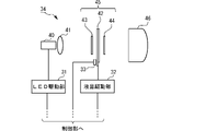
図1は、一実施形態の車両用灯具システムの全体構成を示す図である。図示の車両用灯具システムは、車両前方に対して、ハイビームの照射範囲内にて選択的な光照射を行うことが可能なものであり、制御部1、撮像ユニット2、ライトスイッチ3、冷却水温度センサ4、オイル温度センサ5、一対の前照灯6L、6Rを含んで構成されている。なお、いわゆるロービーム(すれ違いビーム)を照射するための構成については図示を省略する。
FIG. 1 is a diagram showing the overall configuration of a vehicle lamp system according to one embodiment. The illustrated vehicle lighting system is capable of selectively irradiating light in front of the vehicle within the irradiation range of the high beam. It includes a
制御部1は、車両用灯具システムの全体動作を制御するものである。この制御部1は、例えばCPU、ROM、RAM等を備えるコンピュータシステムにおいて所定のプログラムを実行させることによって構成される。この制御部1は、プログラム実行により実現される機能ブロックとして、各前照灯6L、6Rに含まれる液晶素子の加温に関する制御を行う加温制御部11と、液晶素子の動作制御を行う液晶制御部12と、各前照灯6L、6Rに含まれる光源の動作制御を行う光源制御部13と、ハイビームの照射範囲内にて選択的な光照射を行う際の配光パターンを設定する配光設定部14を備える。
The control unit 1 controls the overall operation of the vehicle lamp system. The control unit 1 is configured by executing a predetermined program in a computer system including, for example, a CPU, a ROM, and a RAM. The control unit 1 includes, as functional blocks realized by executing a program, a
撮像ユニット2は、カメラ21と画像処理部22を含んで構成されている。カメラ21は、車両の所定位置(例えば、フロントガラス内側の上方)に設置されており、車両前方の空間を撮影して画像を生成する。画像処理部22は、カメラ21によって生成された画像に対して所定の画像認識処理を行うことにより、車両前方に存在する先行車両、対向車両、歩行者、車線などを検出する。これらの検出された先行車両や対向車両等に応じて上記の配光設定部14により配光パターンが設定され、その配光パターンに応じた像を形成するように液晶制御部12によって液晶駆動部32の動作が制御される。なお、画像処理部22の機能の一部ないし全部が制御部1において実現されてもよい。
The
ライトスイッチ3は、車両の運転席に備わっており、運転者がヘッドライトの点消灯を切り替えたりパッシングを行ったりするために用いられる。
The
冷却水温度センサ4は、車両の冷却水の温度を検出する。オイル温度センサ5は、車両のエンジンオイルの温度を検出する。なお、これら各センサは、通常、車両に元々備わっているので、それらを用いることができる。
A cooling
一対の前照灯6L、6Rは、車両前部の左右にそれぞれ設置されている。各前照灯6L、6Rは、それぞれ、LED駆動部31、液晶駆動部32、前照灯温度センサ33、ランプユニット34を含んで構成されている。
A pair of
LED駆動部31は、光源制御部13から与えられる制御信号に基づいて、ランプユニット34に備わっている光源に含まれるLEDを駆動する。液晶駆動部32は、液晶制御部12から与えられる制御信号に基づいて、ランプユニット34に備わっている液晶素子を駆動する。
The
なお、本実施形態では、制御部1の液晶制御部12と各前照灯6L、6Rの液晶駆動部32によって「液晶動作制御部」が構成されており、制御部1の光源制御部13と各前照灯6L、6RのLED駆動部31によって「光源動作制御部」が構成されている。
In this embodiment, the liquid
前照灯温度センサ33は、各前照灯6L、6Rの筐体内における適宜の位置に設置されており、各前照灯6L、6Rの筐体内の温度、より好ましくはランプユニット34付近の温度を検出する。
The
ランプユニット34は、LED駆動部31、液晶駆動部32の各々により駆動され、車両前方へ種々の配光パターンによる光を照射する。
The
図2は、ランプユニットの構成例を示す図である。図示の例のランプユニット34は、光源40、集光レンズ41、液晶パネル42、一対の偏光板43、44、投影レンズ46を含んで構成されている。なお、液晶パネル42と一対の偏光板43、44を含んで液晶素子45が構成されている。
FIG. 2 is a diagram showing a configuration example of a lamp unit. The illustrated
光源40は、LED(半導体発光素子)を含んで構成されており、LED駆動部31によって駆動されて光を放出する。集光レンズ41は、光源40から放出される光を集光して液晶素子45へ入射させる。
The
液晶素子45は、液晶駆動部32によって駆動されて、入射する光に変調を与えることにより種々の配光パターンに対応する像を形成する。この液晶素子45において、一対の偏光板43、44は、液晶パネル42を挟んで対向配置されている。各偏光板43、44と液晶パネル42との間は密着しておらず所定の間隙が設けられている。本実施形態では、一対の偏光板43、44は、各々の吸収軸を略直交させるように配置されている。各偏光板43、44としては、例えばワイヤーグリッド偏光板を用いることが好ましい。
The
また、液晶パネル42としては、垂直配向型の液晶パネルが用いられている。すなわち、液晶素子45は、電圧無印加時において光透過率が極めて低い状態(実質的に遮光状態)となるノーマリーブラック型の液晶素子として構成されている。
As the
投影レンズ46は、液晶素子45によって形成される光の像を車両前方へ投影する。それにより、光の像に対応した配光パターンが車両前方に形成される。
The
なお、図2に示すように、前照灯温度センサ33は、液晶パネル42の近傍(例えば、基板面上)に設置されることが好ましい。それにより、液晶パネル42の温度をより確実に検出することができる。
In addition, as shown in FIG. 2, the
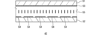
図3は、液晶パネルの構成例を示す模式的な断面図である。図示の液晶パネル42は、第1基板51、第2基板52、第1電極53、第2電極54および液晶層55を含んで構成されている。
FIG. 3 is a schematic cross-sectional view showing a configuration example of a liquid crystal panel. The illustrated
第1基板51および第2基板52は、それぞれ例えばガラス基板、プラスチック基板等の透明基板である。図示のように、第1基板51と第2基板52は、所定の間隙(例えば4μm程度)を設けて貼り合わされている。
The
第1電極53は、第1基板51の一面側に設けられている。同様に、第2電極54は、第2基板52の一面側に設けられている。第1電極53および第2電極54は、それぞれ例えばインジウム錫酸化物(ITO)などの透明導電膜を適宜パターニングすることによって構成されている。これら第1電極53と第2電極54との重なる領域の各々が画素領域(光変調領域)となり、それら画素領域ごとに個別に入射光に対して変調を与えることができる。
The
なお、図示を省略するが、第1基板51と第2基板52の各々の一面側には、各電極を覆うようにして配向膜が設けられている。
Although illustration is omitted, an alignment film is provided on one surface side of each of the
液晶層55は、第1基板51と第2基板52の間に設けられている。本実施形態においては、誘電率異方性Δεが負の液晶材料を用いて液晶層55が構成される。液晶材料の屈折率異方性Δnは、例えば0.09程度である。液晶層55に図示された太線は、液晶層55における液晶分子の配向方向を模式的に示したものである。本実施形態の液晶層55は、電圧無印加時における液晶分子の配向方向が第1基板51および第2基板52の各基板面に対して略垂直(例えば89.9°など)となる垂直配向に設定されている。なお、液晶層55の動作モードは例示した垂直配向モードに限られず、TNモードやIPSモードなど種々の動作モードを用いることができる。
A
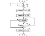
図4は、制御部による動作手順を示すフローチャートである。ここでは、車両の始動後において環境温度が極低温である場合に、ランプユニット34の光源40から放出する光を利用して液晶素子45を加温してその温度を速やかに上昇させるための制御における動作手順が示されている。なお、処理に矛盾を生じない限りにおいて処理順序を入れ替えてもよく、図示の処理順序にのみ限定されない。また、車両が始動したことは、例えばイグニッションスイッチ等の動作状態に基づいて検出される。
FIG. 4 is a flow chart showing an operation procedure by the control unit. Here, when the ambient temperature is extremely low after the vehicle is started, the
制御部1の加温制御部11は、液晶素子45の温度が一定基準を満たす低温と推定される状態であるか否かを判定する(ステップS11)。本実施形態では、各前照灯6L、6Rの前照灯温度センサ33により検出される温度に基づいて、例えばマイナス20℃以下である場合には低温と推定される状態であると判定される。なお、2つの前照灯温度センサ33により2つの温度が検出されるので、例えばいずれか低い温度を用いて判定を行ってもよいし、2つの温度の平均値を用いて判定を行ってもよい。
The
さらに、冷却水温度センサ4やオイル温度センサ5により検出される温度に基づいて一定基準を満たす低温と推定される状態であるか否かを判定してもよい。この場合、液晶素子45の温度と冷却水やオイルの各温度との相関関係を予め実験などで求めておき、そのデータに基づいて液晶素子45の温度を推定すればよい。
Furthermore, based on the temperatures detected by the cooling
低温ではない場合には(ステップS11;NO)、ステップS11の判定が一定間隔で繰り返される。このため、車両の始動後、しばらく時間が経過した後に何らかの原因でランプユニット34の温度が低下した場合であっても、その時点で液晶素子45を温める動作を開始させることができる。この場合、車両が停車した状態であるときに動作を開始させるのが好ましい。
If the temperature is not low (step S11; NO), the determination of step S11 is repeated at regular intervals. Therefore, even if the temperature of the
低温である場合には(ステップS11;YES)、制御部1の加温制御部11から指示を受けた液晶制御部12は、液晶駆動部32に制御信号を与えることにより、液晶素子45を遮光状態に制御する(ステップS12)。なお、本実施形態の液晶素子45はノーマリーブラック型であるため、その状態(電圧無印加状態)を維持するように液晶駆動部32へ制御信号が与えられる。
If the temperature is low (step S11; YES), the liquid
なお、液晶素子45がノーマリーホワイト型であった場合には、液晶素子45を遮光状態とする必要があるので、そのような駆動が行われるように制御部1の液晶制御部12から液晶駆動部32へ制御信号が与えられる。
When the
次に、制御部1の加温制御部11から指示を受けた光源制御部13は、各前照灯6L、6RのLED駆動部31に制御信号を与えることにより、各光源40を点灯状態に制御する(ステップS13)。ここでは、例えば各光源40のLEDに対してその定格電流値よりも大きい値の電流を流すようにしてもよい。このような状態でLEDを点灯させるのは非常に短い時間であり、また環境温度が極低温であるので、LEDに損傷を与えることはない。
Next, the light
このとき、液晶素子45が遮光状態に制御されているので、各前照灯6L、6Rから外部へは光がほぼ漏れない。そして、各光源40から放出される光を利用して液晶素子45を加温してその温度を上昇させることで液晶素子45の応答性を高めることができる。例えば、光源40からの光が偏光板43、44に吸収され、各偏光板43、44の温度が上昇すると、その熱が液晶パネル42に伝搬し、液晶パネル42の温度も上昇する。それにより、加温を行うことができる。
At this time, since the
制御部1の加温制御部11は、各光源40を点灯状態に制御してから所定時間が経過したか否かを判定する(ステップS14)。ここでは、予め定めた一定値の時間としてもよいし、前照灯温度センサ33により検出された温度の大小に応じて、温度が低いほど長く設定される時間であってもよい。
The
所定時間は、例えば液晶素子45の温度がマイナス20℃より高くなるのに必要な時間を目安に設定されることが好ましく、例えば数十秒間~1分間程度に設定することができる。液晶素子45の諸条件や駆動電圧にも依存するが一般的にマイナス20℃以上となればオン時の応答時間が200ms程度となり、パッシング等の配光制御に対して十分に対応可能となるからである。
The predetermined time is preferably set based on, for example, the time required for the temperature of the
所定時間が経過しない場合に(ステップS14;NO)、制御部1の加温制御部11は、液晶素子45の温度が所定温度以上になったか否かを判定する(ステップS15)。所定温度以上となっていない場合には(ステップS15;NO)、ステップS14に戻る。この処理を行うことで、仮に所定時間が経過していなくても液晶素子45が十分に加温された場合には光源40の点灯を停止させることで、必要以上に液晶素子45の温度が上昇することを回避できる。
If the predetermined time has not elapsed (step S14; NO), the
所定時間が経過した場合(ステップS14;YES)、または液晶素子45の温度が所定温度以上になった場合に(ステップS15;YES)、制御部1の加温制御部11から指示を受けた光源制御部13は、各前照灯6L、6RのLED駆動部31に制御信号を与えることにより、各光源40を消灯状態に制御する(ステップS16)。なお、ライトスイッチ3が操作され、ハイビームの照射が指示されている場合には、制御部1の光源制御部13は、消灯状態とせずに、各光源40をLEDの定格電流値以下で点灯させるように制御する。その後、ステップS11へ戻る。
When the predetermined time has passed (step S14; YES), or when the temperature of the
以上のような実施形態によれば、液晶素子を用いる車両用灯具システムにおいて、極低温の環境下においては光源40からの光を利用して液晶素子45が速やかに加温されて応答性が高まるので、極低温の環境下でも確実に光照射を行うことが可能となる。
According to the above-described embodiments, in a vehicle lighting system using a liquid crystal element, the
なお、本発明は上記した実施形態の内容に限定されるものではなく、本発明の要旨の範囲内において種々に変形して実施をすることが可能である。例えば、上記した実施形態では液晶素子45を加温するために光源40を点灯状態に制御した際に、所定時間が経過した場合と、液晶素子45の温度が所定値以上となった場合の何れかにおいて光源40の点灯状態を停止させていたが、何れか一方のみの判定を行うようにしてもよい。すなわち、時間については判定することなく温度により光源40の点消灯を判定してもよいし、その逆に、温度については判定することなく時間により光源40の点消灯を判定してもよい。
It should be noted that the present invention is not limited to the contents of the above-described embodiments, and various modifications can be made within the scope of the gist of the present invention. For example, in the above-described embodiment, when the
また、液晶素子にナノ粒子を添加することにより、液晶素子の加温の効率化を図ることも好ましい。この場合のランプユニット34aの構成例を図5に示す。例えば、液晶素子45の液晶パネル42aの液晶層に、近赤外線吸収材料としてナノメートルサイズの金属粒子(例えば、金粒子)を添加しておく。あるいは、液晶パネル42aの配向膜ないしそれ以外の保護膜など、基板上に設けられる膜にナノメートルサイズの金属粒子を添加しておく。そして、上記した光源40による加熱を行う際に、併せて液晶パネル42aに対して光源35により近赤外線を照射させるようにする。図示のように、光源35からの近赤外線(例えば、波長約3μm以下)は各偏光板43、44を介さず直接的に液晶パネル42aへ照射させることが好ましい。この構成では、液晶パネル42a内の金属粒子により近赤外線が吸収されることにより液晶パネル42aの温度をさらに効率的に上昇させることができる。なお、光源40から可視光とともに近赤外線も十分に放出されている場合には、光源35を省略してもよい。
It is also preferable to improve the efficiency of heating the liquid crystal element by adding nanoparticles to the liquid crystal element. FIG. 5 shows a configuration example of the
なお、図5の構成を採用する場合には、投影レンズ46、投影レンズ46側の偏光板44、あるいは図示しないランプユニット34aの筐体(アウターレンズ等)に赤外線吸収機能を持たせておくことが好ましい。それにより、外部から入射する太陽光等の赤外線による意図しない液晶パネル42aの加熱を防ぐことができる。
5, the
1:制御部、2:撮像ユニット、3:ライトスイッチ、4:冷却水温度センサ、5:オイル温度センサ、6L、6R:前照灯、11:加温制御部、12:液晶制御部、13:光源制御部、14:配光設定部、31:LED駆動部、32:液晶駆動部、33:前照灯温度センサ、34:ランプユニット、40:光源、41:集光レンズ、42:液晶パネル、43、44:偏光板、45:液晶素子、46:投影レンズ 1: control unit, 2: imaging unit, 3: light switch, 4: cooling water temperature sensor, 5: oil temperature sensor, 6L, 6R: headlights, 11: heating control unit, 12: liquid crystal control unit, 13 : light source control unit 14: light distribution setting unit 31: LED driving unit 32: liquid crystal driving unit 33: headlight temperature sensor 34: lamp unit 40: light source 41: condenser lens 42: liquid crystal Panel, 43, 44: polarizing plate, 45: liquid crystal element, 46: projection lens
Claims (10)
前記光源を制御する光源動作制御部、前記液晶素子を制御する液晶動作制御部および配光設定部と、を含む制御装置と、
車両前方の空間を撮影して画像を生成し、画像認識処理を行う撮像ユニットと、
を含む車両用前照灯システムであって、
前記液晶素子は、一面側にパターニングされた透明導電膜よりなる第1電極を備える第1基板、前記第1基板の一面側に対向して配置され前記第1基板側にパターニングされた透明導電膜よりなる第2電極を備える第2基板および前記第1基板と前記第2基板との間に配置される液晶層を備え、前記第1電極と前記第2電極が重なる領域を画素領域とする液晶パネルと、前記液晶パネルを挟んで対向配置される一対の偏光板と、を含み、
前記液晶素子は、前記光源から出射した光が入射して、入射光に変調を与えて配光パターンに対応する像を形成するものであり、
前記液晶動作制御部は、前記撮像ユニットによる画像認識結果に基づいて前記配光設定部によって設定された配光パターンに応じた像を形成するように前記液晶素子の動作を制御するものであり、
前記温度センサは、前記液晶パネルの基板面上に設置されて前記液晶パネルの温度を検出するものであり、
前記制御装置は、
車両の始動後に前記温度センサにより検出される温度に基づいて前記液晶素子の温度が所定の基準温度よりも低温か否かを判定し、
前記液晶素子が前記基準温度よりも低温と判定された場合には、前記液晶動作制御部が前記液晶素子の前記画素領域を遮光状態に制御するとともに前記光源動作制御部が前記光源を点灯状態に制御することにより前記液晶素子を加温し、
前記液晶パネルが前記基準温度よりも低温でないと判定された場合には、所定間隔で前記液晶素子が前記基準温度よりも低温か否かの判定を繰り返して実施する、
車両用前照灯システム。 a lamp unit that includes a light source, a liquid crystal element that modulates light incident from the light source, a lens that projects a light image formed by the liquid crystal element, and a temperature sensor, and that irradiates a high beam forward of the vehicle;
a control device including a light source operation control unit that controls the light source, a liquid crystal operation control unit that controls the liquid crystal element, and a light distribution setting unit;
an imaging unit that captures the space in front of the vehicle, generates an image, and performs image recognition processing;
A vehicle headlight system comprising:
The liquid crystal element includes a first substrate having a first electrode made of a transparent conductive film patterned on one surface side, and a transparent conductive film arranged facing one surface side of the first substrate and patterned on the first substrate side. and a liquid crystal layer disposed between the first substrate and the second substrate, wherein the region where the first electrode and the second electrode overlap is a pixel region. A panel and a pair of polarizing plates arranged opposite to each other with the liquid crystal panel interposed therebetween,
The liquid crystal element receives the light emitted from the light source and modulates the incident light to form an image corresponding to the light distribution pattern,
The liquid crystal operation control section controls the operation of the liquid crystal element so as to form an image according to the light distribution pattern set by the light distribution setting section based on the image recognition result by the imaging unit,
The temperature sensor is installed on the substrate surface of the liquid crystal panel and detects the temperature of the liquid crystal panel,
The control device is
determining whether the temperature of the liquid crystal element is lower than a predetermined reference temperature based on the temperature detected by the temperature sensor after the vehicle is started;
When the temperature of the liquid crystal element is determined to be lower than the reference temperature, the liquid crystal operation control section controls the pixel region of the liquid crystal element to be in a light-shielding state, and the light source operation control section turns on the light source. heating the liquid crystal element by controlling
If it is determined that the liquid crystal panel is not at a temperature lower than the reference temperature, repeatedly determining whether the liquid crystal element is at a lower temperature than the reference temperature at predetermined intervals.
Vehicle headlight system.
請求項1に記載の車両用前照灯システム。 The pair of polarizing plates are arranged with absorption axes substantially orthogonal to each other,
The vehicle headlamp system according to claim 1.
請求項1または請求項2に記載の車両用前照灯システム。 The liquid crystal panel is of a vertical alignment type,
The vehicle headlamp system according to claim 1 or 2.
請求項3に記載の車両用前照灯システム。 In the control device, when it is determined that the temperature of the liquid crystal element is lower than the reference temperature after the vehicle is started, the liquid crystal operation control unit controls the liquid crystal element to maintain the liquid crystal element in a non-voltage-applied state. A light source operation control unit heats the liquid crystal element by controlling the light source to be in a lighting state.
The vehicle headlamp system according to claim 3.
前記液晶素子が前記基準温度よりも低温と判定された場合には、前記光源動作制御部が、前記LEDを当該LEDの定格電流値よりも大きい値の電流を流すように制御することにより前記液晶素子を加温する、
請求項1から請求項4のいずれか1項に記載の車両用前照灯システム。 the light source is an LED,
When it is determined that the temperature of the liquid crystal element is lower than the reference temperature, the light source operation control unit controls the LED so that a current larger than the rated current value of the LED flows. to heat the element,
The vehicle headlamp system according to any one of claims 1 to 4.
請求項5に記載の車両用前照灯システム。 The control device determines that the temperature of the liquid crystal element is lower than the reference temperature, and the light source operation control unit controls the light source to turn on the light source to heat the liquid crystal element for a predetermined time. or when the temperature of the liquid crystal element reaches the reference temperature or higher, the lighting state of the LED is controlled to stop the heating;
The vehicle headlamp system according to claim 5.
請求項1から請求項6の何れか1項に記載の車両用前照灯システム。 Nanoparticles are added to the liquid crystal element,
The vehicle headlamp system according to any one of claims 1 to 6.
請求項7に記載の車両用前照灯システム。 further comprising an infrared light source, wherein the heating is performed by the light source and light emitted from the infrared light source;
The vehicle headlamp system according to claim 7.
各前記偏光板は、前記液晶パネルと所定の間隙が設けられ、
前記赤外光源からの赤外光は、前記偏光板を介さず直接的に前記液晶パネルに照射される、
請求項8に記載の車両用前照灯システム。 In the liquid crystal element, the pair of polarizing plates are arranged to face each other with the liquid crystal panel interposed therebetween,
Each polarizing plate is provided with a predetermined gap from the liquid crystal panel,
Infrared light from the infrared light source is directly irradiated to the liquid crystal panel without passing through the polarizing plate.
The vehicle headlamp system according to claim 8.
前記光源を制御する光源動作制御部、前記液晶素子を制御する液晶動作制御部および配光設定部と、を含む制御装置と、
車両前方の空間を撮影して画像を生成し、画像認識処理を行う撮像ユニットと、
を含む車両用前照灯システムであって、
前記液晶素子は、一面側にパターニングされた透明導電膜よりなる第1電極を備える第1基板、前記第1基板の一面側に対向して配置され前記第1基板側にパターニングされた透明導電膜よりなる第2電極を備える第2基板および前記第1基板と前記第2基板との間に配置される液晶層を備え、前記第1電極と前記第2電極が重なる領域を画素領域とする液晶パネルと、前記液晶パネルを挟んで対向配置される一対の偏光板と、を含み、
前記液晶素子は、前記光源から出射した光が入射して、入射光に変調を与えて配光パターンに対応する像を形成するものであり、
前記液晶動作制御部は、前記撮像ユニットによる画像認識結果に基づいて前記配光設定部によって設定された配光パターンに応じた像を形成するように前記液晶素子の動作を制御するものであり、
前記温度センサは、前記車両の冷却水の温度又は前記車両のエンジンオイルの温度を検出するものであり、
前記制御装置は、
前記温度センサにより検出される温度に基づいて前記液晶素子の温度が所定の基準温度よりも低温か否かを推定し、
車両の始動後に前記液晶素子が前記基準温度よりも低温と推定された場合には、車両が停止した状態で、前記液晶動作制御部が前記液晶素子の前記画素領域を遮光状態に制御するとともに前記光源動作制御部が前記光源を点灯状態に制御することにより前記液晶素子を加温し、
前記液晶パネルが前記基準温度よりも低温でないと判定された場合には、所定間隔で前記液晶素子が前記基準温度よりも低温か否かの判定を繰り返して実施する、
車両用前照灯システム。
a lamp unit that includes a light source, a liquid crystal element that modulates light incident from the light source, a lens that projects a light image formed by the liquid crystal element, and a temperature sensor, and that irradiates a high beam forward of the vehicle;
a control device including a light source operation control unit that controls the light source, a liquid crystal operation control unit that controls the liquid crystal element, and a light distribution setting unit;
an imaging unit that captures the space in front of the vehicle, generates an image, and performs image recognition processing;
A vehicle headlight system comprising:
The liquid crystal element includes a first substrate having a first electrode made of a transparent conductive film patterned on one surface side, and a transparent conductive film arranged facing one surface side of the first substrate and patterned on the first substrate side. and a liquid crystal layer disposed between the first substrate and the second substrate, wherein the region where the first electrode and the second electrode overlap is a pixel region. A panel and a pair of polarizing plates arranged opposite to each other with the liquid crystal panel interposed therebetween,
The liquid crystal element receives the light emitted from the light source and modulates the incident light to form an image corresponding to the light distribution pattern,
The liquid crystal operation control section controls the operation of the liquid crystal element so as to form an image according to the light distribution pattern set by the light distribution setting section based on the image recognition result by the imaging unit,
The temperature sensor detects the temperature of cooling water of the vehicle or the temperature of the engine oil of the vehicle,
The control device is
estimating whether the temperature of the liquid crystal element is lower than a predetermined reference temperature based on the temperature detected by the temperature sensor;
When the temperature of the liquid crystal element is estimated to be lower than the reference temperature after the vehicle is started, the liquid crystal operation control section controls the pixel region of the liquid crystal element to be in a light-shielding state while the vehicle is stopped. A light source operation control unit heats the liquid crystal element by controlling the light source to a lighting state,
If it is determined that the liquid crystal panel is not at a temperature lower than the reference temperature, repeatedly determining whether the liquid crystal element is at a lower temperature than the reference temperature at predetermined intervals.
Vehicle headlight system.
Priority Applications (3)
| Application Number | Priority Date | Filing Date | Title |
|---|---|---|---|
| JP2018155740A JP7193270B2 (en) | 2018-08-22 | 2018-08-22 | Vehicle lighting control device, vehicle lighting control method, vehicle lighting system |
| EP19190553.8A EP3614043A1 (en) | 2018-08-22 | 2019-08-07 | Control device for vehicular lamp, control method for vehicular lamp, vehicular lamp system |
| US16/547,771 US11009734B2 (en) | 2018-08-22 | 2019-08-22 | Control device for vehicular lamp, control method for vehicular lamp, vehicular lamp system |
Applications Claiming Priority (1)
| Application Number | Priority Date | Filing Date | Title |
|---|---|---|---|
| JP2018155740A JP7193270B2 (en) | 2018-08-22 | 2018-08-22 | Vehicle lighting control device, vehicle lighting control method, vehicle lighting system |
Publications (3)
| Publication Number | Publication Date |
|---|---|
| JP2020029166A JP2020029166A (en) | 2020-02-27 |
| JP2020029166A5 JP2020029166A5 (en) | 2021-08-26 |
| JP7193270B2 true JP7193270B2 (en) | 2022-12-20 |
Family
ID=67587394
Family Applications (1)
| Application Number | Title | Priority Date | Filing Date |
|---|---|---|---|
| JP2018155740A Active JP7193270B2 (en) | 2018-08-22 | 2018-08-22 | Vehicle lighting control device, vehicle lighting control method, vehicle lighting system |
Country Status (3)
| Country | Link |
|---|---|
| US (1) | US11009734B2 (en) |
| EP (1) | EP3614043A1 (en) |
| JP (1) | JP7193270B2 (en) |
Families Citing this family (2)
| Publication number | Priority date | Publication date | Assignee | Title |
|---|---|---|---|---|
| WO2021054276A1 (en) * | 2019-09-19 | 2021-03-25 | 株式会社小糸製作所 | Infrared lighting unit system for vehicle, infrared sensor system for vehicle, and lighting unit with built-in infrared sensor and lighting unit with built-in optical sensor for vehicle |
| DE102022125753A1 (en) | 2022-10-06 | 2024-04-11 | Marelli Automotive Lighting Reutlingen (Germany) GmbH | Device and method for temperature stabilization of a matrix headlight |
Citations (6)
| Publication number | Priority date | Publication date | Assignee | Title |
|---|---|---|---|---|
| JP2008304589A (en) | 2007-06-06 | 2008-12-18 | Stanley Electric Co Ltd | Liquid crystal display device |
| JP2013001234A (en) | 2011-06-16 | 2013-01-07 | Koito Mfg Co Ltd | Head light control device for vehicle |
| JP2013235259A (en) | 2012-04-13 | 2013-11-21 | Nitto Denko Corp | Optical member, polarizing plate set and liquid crystal display device |
| JP2015031793A (en) | 2013-08-01 | 2015-02-16 | 株式会社デンソー | Head-up display device |
| JP2015056600A (en) | 2013-09-13 | 2015-03-23 | 日本精機株式会社 | Laser source controller and display device for vehicle |
| US20160377251A1 (en) | 2015-06-24 | 2016-12-29 | Lg Electronics Inc. | Headlamp for vehicle |
Family Cites Families (10)
| Publication number | Priority date | Publication date | Assignee | Title |
|---|---|---|---|---|
| JP3514946B2 (en) * | 1997-05-29 | 2004-04-05 | 日産自動車株式会社 | Liquid crystal display |
| US7370983B2 (en) * | 2000-03-02 | 2008-05-13 | Donnelly Corporation | Interior mirror assembly with display |
| JP3602843B2 (en) * | 2002-06-12 | 2004-12-15 | シャープ株式会社 | Liquid crystal display |
| JP2005183327A (en) | 2003-12-24 | 2005-07-07 | Stanley Electric Co Ltd | Vehicle headlamp |
| KR100599731B1 (en) * | 2004-08-20 | 2006-07-12 | 삼성에스디아이 주식회사 | A liquid crystal display and a driving method thereof |
| DE102008008664B4 (en) * | 2008-02-12 | 2011-03-31 | Continental Automotive Gmbh | Vehicle headlamp with quick removal of moisture or ice on its shroud |
| JP2014002235A (en) * | 2012-06-18 | 2014-01-09 | Stanley Electric Co Ltd | Three-dimensional image display device and illumination device |
| DE112013003050B4 (en) * | 2012-06-29 | 2023-06-22 | Koito Manufacturing Co., Ltd. | Vehicle light and method for controlling the same |
| JP2015127756A (en) * | 2013-12-27 | 2015-07-09 | 本田技研工業株式会社 | Liquid crystal display device |
| US10214141B2 (en) * | 2014-06-18 | 2019-02-26 | Maxell, Ltd. | Headlight device and vehicle device using same |
-
2018
- 2018-08-22 JP JP2018155740A patent/JP7193270B2/en active Active
-
2019
- 2019-08-07 EP EP19190553.8A patent/EP3614043A1/en not_active Withdrawn
- 2019-08-22 US US16/547,771 patent/US11009734B2/en active Active
Patent Citations (6)
| Publication number | Priority date | Publication date | Assignee | Title |
|---|---|---|---|---|
| JP2008304589A (en) | 2007-06-06 | 2008-12-18 | Stanley Electric Co Ltd | Liquid crystal display device |
| JP2013001234A (en) | 2011-06-16 | 2013-01-07 | Koito Mfg Co Ltd | Head light control device for vehicle |
| JP2013235259A (en) | 2012-04-13 | 2013-11-21 | Nitto Denko Corp | Optical member, polarizing plate set and liquid crystal display device |
| JP2015031793A (en) | 2013-08-01 | 2015-02-16 | 株式会社デンソー | Head-up display device |
| JP2015056600A (en) | 2013-09-13 | 2015-03-23 | 日本精機株式会社 | Laser source controller and display device for vehicle |
| US20160377251A1 (en) | 2015-06-24 | 2016-12-29 | Lg Electronics Inc. | Headlamp for vehicle |
Also Published As
| Publication number | Publication date |
|---|---|
| US20200063940A1 (en) | 2020-02-27 |
| US11009734B2 (en) | 2021-05-18 |
| EP3614043A1 (en) | 2020-02-26 |
| JP2020029166A (en) | 2020-02-27 |
Similar Documents
| Publication | Publication Date | Title |
|---|---|---|
| WO2018225655A1 (en) | Vehicular headlamp system | |
| JP5468464B2 (en) | Vehicle lighting | |
| JP7193270B2 (en) | Vehicle lighting control device, vehicle lighting control method, vehicle lighting system | |
| EP3572722B1 (en) | Vehicular lamp, vehicular lamp system | |
| JP7177617B2 (en) | Lamp units, vehicle lighting systems | |
| EP3599417A1 (en) | Vehicular lamp | |
| CN110006002B (en) | Lighting device | |
| US10788185B2 (en) | Vehicular lamp system configured to change the extent of high-low ratio of the illumination distributions | |
| JP7234020B2 (en) | lighting units, lighting systems | |
| JP7053331B2 (en) | Lighting equipment, light projection system | |
| KR20110084785A (en) | Head lamp device | |
| JP6846294B2 (en) | Vehicle headlight system | |
| JP2020029166A5 (en) | ||
| JP7493330B2 (en) | Vehicle lighting system | |
| JP2019140031A (en) | Lighting appliance system for vehicle | |
| JP7219085B2 (en) | Lamp units, vehicle lighting systems | |
| JP2019102380A (en) | Vehicular lighting fixture system | |
| JP7202934B2 (en) | Liquid crystal element, lighting device | |
| JP2019142413A (en) | Method for adjusting emission light color of headlight lamp unit for vehicle | |
| JP7001370B2 (en) | Vehicle headlight system and its control method | |
| WO2022153754A1 (en) | Headlight control device, headlight control method, and headlight system | |
| JP2019110084A (en) | Illumination device | |
| JPH04162302A (en) | Illumination device | |
| JP2024149017A (en) | Liquid crystal elements, lighting devices, vehicle lighting systems | |
| JP2021046149A (en) | Lighting system for vehicle |
Legal Events
| Date | Code | Title | Description |
|---|---|---|---|
| A521 | Request for written amendment filed |
Free format text: JAPANESE INTERMEDIATE CODE: A523 Effective date: 20210709 |
|
| A621 | Written request for application examination |
Free format text: JAPANESE INTERMEDIATE CODE: A621 Effective date: 20210709 |
|
| A977 | Report on retrieval |
Free format text: JAPANESE INTERMEDIATE CODE: A971007 Effective date: 20220525 |
|
| A131 | Notification of reasons for refusal |
Free format text: JAPANESE INTERMEDIATE CODE: A131 Effective date: 20220531 |
|
| A521 | Request for written amendment filed |
Free format text: JAPANESE INTERMEDIATE CODE: A523 Effective date: 20220714 |
|
| TRDD | Decision of grant or rejection written | ||
| A01 | Written decision to grant a patent or to grant a registration (utility model) |
Free format text: JAPANESE INTERMEDIATE CODE: A01 Effective date: 20221111 |
|
| A61 | First payment of annual fees (during grant procedure) |
Free format text: JAPANESE INTERMEDIATE CODE: A61 Effective date: 20221208 |
|
| R150 | Certificate of patent or registration of utility model |
Ref document number: 7193270 Country of ref document: JP Free format text: JAPANESE INTERMEDIATE CODE: R150 |