WO2015015620A1 - Data transfer device, data output device, data transfer method, and data output method - Google Patents
Data transfer device, data output device, data transfer method, and data output method Download PDFInfo
- Publication number
- WO2015015620A1 WO2015015620A1 PCT/JP2013/070922 JP2013070922W WO2015015620A1 WO 2015015620 A1 WO2015015620 A1 WO 2015015620A1 JP 2013070922 W JP2013070922 W JP 2013070922W WO 2015015620 A1 WO2015015620 A1 WO 2015015620A1
- Authority
- WO
- WIPO (PCT)
- Prior art keywords
- data
- frame
- output
- transmission rate
- gbps
- Prior art date
Links
Images


Classifications
-
- H—ELECTRICITY
- H04—ELECTRIC COMMUNICATION TECHNIQUE
- H04L—TRANSMISSION OF DIGITAL INFORMATION, e.g. TELEGRAPHIC COMMUNICATION
- H04L12/00—Data switching networks
- H04L12/28—Data switching networks characterised by path configuration, e.g. LAN [Local Area Networks] or WAN [Wide Area Networks]
- H04L12/40—Bus networks
- H04L12/4013—Management of data rate on the bus
- H04L12/40136—Nodes adapting their rate to the physical link properties
-
- Y—GENERAL TAGGING OF NEW TECHNOLOGICAL DEVELOPMENTS; GENERAL TAGGING OF CROSS-SECTIONAL TECHNOLOGIES SPANNING OVER SEVERAL SECTIONS OF THE IPC; TECHNICAL SUBJECTS COVERED BY FORMER USPC CROSS-REFERENCE ART COLLECTIONS [XRACs] AND DIGESTS
- Y02—TECHNOLOGIES OR APPLICATIONS FOR MITIGATION OR ADAPTATION AGAINST CLIMATE CHANGE
- Y02D—CLIMATE CHANGE MITIGATION TECHNOLOGIES IN INFORMATION AND COMMUNICATION TECHNOLOGIES [ICT], I.E. INFORMATION AND COMMUNICATION TECHNOLOGIES AIMING AT THE REDUCTION OF THEIR OWN ENERGY USE
- Y02D30/00—Reducing energy consumption in communication networks
- Y02D30/50—Reducing energy consumption in communication networks in wire-line communication networks, e.g. low power modes or reduced link rate
Definitions
- the present invention relates to a data transfer device, a data output device, a data transfer method, and a data output method.
- Ethernet registered trademark
- data transfer devices such as Ethernet switches are expected to support multiple data transmission rates such as 1 Gbps, 10 Gbps, 40 Gbps, and 100 Gbps.
- the data transfer apparatus is an Ethernet switch (simply referred to as a switch) will be described.
- FIG. 20 is a diagram illustrating a configuration example of a conventional network system.
- the network system shown in FIG. 20 includes a plurality of servers (Server) # 00, # 01, # 10 to # 14, and a plurality of switches (SW) # 1 to # 5.
- the data (frame) is server # 00 ⁇ SW # 1 ⁇ SW # 2 ⁇ SW # 4 ⁇ server #. 10 routes are transmitted. In this transmission route, the throughput (data transmission performance) of each transmission path connecting server # 00 to server # 10 is 10 Gbps, and each SW # 1, # 2, # 4 is simple. Data transfer is performed.
- FIG. 20 data transferred between the devices is indicated by arrows for convenience.
- a 100 Gbps frame is transmitted on a transmission path between devices, there is a method of transmitting using a plurality of lanes such as 4 lanes and 10 lanes.
- FIG. 21 is a diagram schematically showing data transfer in a conventional data relay device, and
- FIG. 22 is a diagram showing the transfer method.
- the switch includes a switch chip having a function of outputting (transferring) an input frame corresponding to a desired destination.
- each shaded rectangle represents data
- one rectangle represents one unit of data.
- One rectangle (data) has a data size of 8 bytes, for example.
- a collection of multiple data is called a frame.
- the switch chip shown in FIG. 21 is configured to be able to input 10 Gbps and 100 Gbps frames and to be able to output 10 Gbps and 100 Gbps frames. In other words, frame transfer can be performed with all combinations of 10 Gbps and 100 Gbps inputs and 10 Gbps and 100 Gbps outputs.
- FIG. 21 the internal operation by the combination of input and output frame speeds in the switch chip is indicated by dotted arrows.
- a frame is transferred by either a CT (Cut Through) method or an S & F (Store & Forward) method.
- CT Cut Through
- S & F Store & Forward
- the CT method is a method of transferring received data one after another before reading all the data of the input frame. Since the output data transmission rate is equal to or less than the input data transmission rate, even if the data is transferred by CT, the data is not exhausted in the switch chip and the output frame is not interrupted. And sent out.
- the S & F method is a method in which all data of a received frame is once stored in a buffer inside the switch chip and then transferred. When a frame input at 10 Gbps is output at 100 Gbps, the output data transmission speed is faster than that of the input data. Therefore, when the CT method is used for output, the output data is exhausted inside the switch. That is, data cannot be sent continuously.
- the CT method can be transferred with less latency than the S & F method. Therefore, it can be said that the CT method is superior to the S & F method in terms of performance. Further, when data transfer can be performed by the CT method, it can also be performed by the S & F method. In order to perform processing such as frame checking, there is a case where the data is transferred by the S & F method so as to be buffered once in the switch chip.
- Throughput here refers to the amount of data per unit time that can be transferred by the switch chip, and the larger the throughput value, the greater the amount of data that can be processed.
- Latency refers to the time required for data to pass through the switch chip. The smaller the latency value, the faster the data transfer process. JP-A-6-97904
- the S & F method is used when a frame received via a 10 Gbps transmission path is transferred to a 100 Gbps transmission path.
- the received frame is buffered once in the switch chip and then transferred at a rate of 100 Gbps, so that the latency at the switch chip increases.
- the latency through the switch chip is about several hundred ns.
- an object of the present invention is to improve data transfer efficiency.
- the present invention is not limited to the above-described object, and other effects of the present invention can be achieved by the functions and effects derived from the respective configurations shown in the embodiments for carrying out the invention which will be described later. It can be positioned as one of
- this data transfer device is a data transfer device that transfers data between a plurality of first communication paths and one or more second communication paths, and inputs from each of the plurality of first communication paths.
- Mixed to create mixed data by mixing the received data input from each of the plurality of first communication channels when the data transmission rate of the received data is lower than the data transmission performance value of the second communication channel A data creation unit; and an output unit that outputs the mixed data created by the mixed data creation unit to the second communication path.
- the data transfer method is a data transfer method in a data transfer device that transfers data between a plurality of first communication paths and one or more second communication paths, wherein the plurality of first communication paths
- the data transmission rate of the received data input from each of the channels is lower than the data transmission performance value of the second communication channel
- the received data input from each of the plurality of first communication channels is mixed and mixed Data is created, and the created mixed data is output to the second communication path.
- the data output device outputs data to a communication path capable of transmitting a first frame having a first transmission rate and a second frame having a second transmission rate higher than the first transmission rate.
- a data output device for performing a multiplexing processing unit that multiplexes the number of the first frames determined by dividing the second transmission rate by the first transmission rate to create a multiplexed frame;
- An output unit for outputting the multiplexed frame created by the multiplexing processing unit to the communication path.
- data transfer efficiency can be improved.
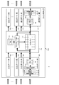
- FIG. 1 is a diagram schematically showing a configuration of a switch chip (data transfer circuit) 100 provided in a switch (data transfer device, data output device) 2 as an example of an embodiment, and FIG. It is a figure which illustrates the structure of the network system 1 which has a switch provided with.
- the network system 1 illustrated in FIG. 2 includes a plurality of servers 3 and a plurality of switches (SW) 2. In the example shown in FIG. 2, seven servers 3 of servers # 00, # 01, and # 10 to # 14 and five switches 2 of switches # 01 to # 05 are provided.
- reference numerals # 00, # 01, and # 10 to # 14 are attached. Use.
- reference numeral # 01 to # 05 are attached when it is necessary to specify one of a plurality of switches, but reference numeral 2 is used to indicate any switch.
- the switch 2 transfers the input data by the frame transfer method.
- Each switch 2 supports data input / output at a plurality of transmission rates, and enables data input and data output at each transmission rate of 1 Gpbs, 10 Gbps, 40 Gbps, and 100 Gbps, for example.
- a frame (first frame) transmitted at a transmission rate of 10 Gbps (first transmission rate) and a frame (first transmission rate) transmitted at a transmission rate of 100 Gbps (second transmission rate) An example in which frames of two types of transmission rates (second frame) are mixed is shown.
- the maximum speed (maximum transmission speed) of 100 Gbps that is, the maximum value of the data transfer rate in the network system 1 is 100 Gbps.
- the network system 1 is not limited to the mixed speed of 100 Gbps and 10 Gbps, but can be implemented with various modifications.
- the specific speed is 100 Gbps and 10 Gbps for easy understanding. Will be described.
- data transmitted at a transmission rate of 10 Gbps is simply referred to as 10 Gbps data or 10 G frame.
- data transmitted at a transmission rate of 100 Gbps is simply referred to as 100 Gbps data or 100 G frame.
- data (frames) transmitted from the servers # 00 and # 01 are transferred to any of the servers # 10 to # 14 via the plurality of switches 2.
- An example is shown.
- the left side in the figure, that is, the servers # 00 and # 01 side may be referred to as the upstream side
- the right side in the figure, that is, the servers # 10 to # 14 side may be referred to as the downstream side.
- the servers # 00 and # 01 and the switches # 02 and # 03 are connected to the switch # 01.
- Switches # 01 and # 04 are connected to the switch # 02, and switches # 01 and # 05 are connected to the switch # 03, respectively.
- Servers # 10 and # 11 and switch # 02 are connected to switch # 04.
- Servers # 12, # 13, # 14 and switch # 03 are connected to switch # 05.
- the switch 2 to which the server 3 is connected may be referred to as an edge switch 2.
- the switch 2 arranged between the switches 2 and connected to the server 3 via another switch 2 may be referred to as a next-stage switch 2.
- the switches # 01, # 04, and # 05 are the edge switches 2
- the switches # 02 and # 03 are the next stage switches 2.
- the maximum values of the data transfer rates supported by the interfaces of the servers # 00, # 10, # 12, and # 13 are 10 Gbps, respectively, and the servers # 01, # 11, and # 14
- the maximum data transfer rate supported by the interface is 100 Gbps each.
- Between server # 00 and switch # 01, between switch # 01 and switch # 02, between switch # 04 and server # 10, between switch # 05 and server # 12, and between switch # 05 and server The throughput of each transmission line with # 13 is 10 Gbps.
- a range (area) with a throughput of 100 Gbps is referred to as a maximum speed transmission area, and is surrounded by a dotted line and indicated by a symbol a in FIG.
- Each switch 2 has the same configuration, and includes the switch chip 100 shown in FIG. That is, the function as each switch 2 is realized by various settings of the switch chip 100.
- the edge switches # 01, # 04, and # 05 are set for the edge portion in the network system 1 configured by a switch group, and the next-stage switches # 02 and # 03 are set for other switches in the system.
- Settings for connecting the switch chip 100 are performed.
- the ports for the edge that is, the ports connected to the server 3 (server side and upstream side) are supported by the interface of the connected server 3. It is set according to the speed.
- each port (switch chip side, downstream side) connected to the other switch 2 in the switches # 01, # 04, and # 05 is fixed to 100 Gbps which is the upper limit in the specification of the network system 1. Is set.
- the ports on the server # 00 and # 01 side match the speed supported by the interface of the server 3 connected via the switch # 01.
- the switch chip side (downstream side) of the switches # 02 and # 03 is set to be fixed at 100 Gbps, which is the upper limit in the specifications of the network system 1.
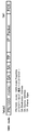
- FIGS. 3 and 4 are diagrams illustrating the configuration of a frame transferred in the network system 1 including the switch 2 as an example of the embodiment.
- FIG. 3 illustrates a 10G mode frame
- FIG. It is a figure which illustrates the frame of a mode.
- FIGS. 3 and 4 In the present storage system 1, the frames shown in FIGS. 3 and 4 are transferred. In FIGS. 3 and 4, the left side is the head of the frame, and the right side is the tail of the frame.
- a 10G mode frame (10G mode frame) is a frame created to pass through a 10 Gbps transmission path.
- a 100G mode frame is a frame created to pass through a 100 Gbps transmission path.
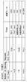
- the 10G mode frame and the 100G mode frame include fields of PR, DA, SA, TP, IP packet (IP Packet), and FCS, respectively.
- the field “PR (Preamble)” includes an 8-byte data storage area, for example.
- 7-byte information indicating the head of data is stored. Specifically, 7-byte data configured by repeating 7 consecutive 1-byte data (10101010) repeating 0 and 1 is stored as information indicating the head of the data.
- 1-byte identification information (data transmission rate information) indicating the transmission rate of the frame is stored in the field “PR”. That is, the data transmission rate information indicates whether the frame is a 10G mode frame or a 100G mode frame.
- 8′b01011011 that is, 1 byte (8 bits) information having a pattern of “01011011” is set as data transmission rate information.
- 8′b01101011 that is, 1 byte (8 bits) information having a pattern of “01101011” is set as data transmission rate information.
- This data transmission rate information is provided following the 7-byte information indicating the head of the data described above.
- 1-byte data transmission rate information (“01011011” or “01101011”) is stored at the trailing end of 01 of 7 bytes indicating the head of data.
- the data transmission rate information of the field “PR” in these 10G mode frame and 100G mode frame is added by the MAC 33 of the switch 2 connected to the server 3 that is the data transmission source in the network system 1, for example.
- the maximum value of the data transfer rate supported by the interface of the server # 00 that is the frame transmission source is 10 Gbps.
- 8'b01011011 is set as data transmission rate information in the PR of the frame received from 00.
- the frame output from the server # 00 becomes a 10G mode frame.
- the switch # 01 on the downstream side sets the PR of the frame received from the server # 01. 8'b01101011 is set as the data transmission rate information.
- the frame output from the server # 01 becomes a 100G mode frame.
- the speed of the interface is determined in the link-up process, and is realized by, for example, an auto-negotiation function. The determination of the interface speed can be realized by using various known methods, and detailed description thereof will be omitted.
- the field “DA” stores information indicating the destination of the frame (Destination Address), and the field “SA” stores information indicating the transmission source of the frame (Source Address).
- the field “TA” stores information indicating the type of the frame, and the field “IP Packet” stores data to be transferred (IP packet).
- the field “FCS” stores data error check data.
- the switch chip 100 includes n (n is a natural number) input ports 20, m (m is a natural number) output ports 30, and a control unit 10.
- the switch chip 100 is configured to be able to input 10 Gbps and 100 Gbps frames, and to be able to output 10 Gbps and 100 Gbps frames. In other words, frame transfer can be performed with all combinations of 10 Gbps and 100 Gbps inputs and 10 Gbps and 100 Gbps outputs.
- Data are input to the input port 20 from a server or another switch.
- reference numerals # 1 to #n are given when it is necessary to specify one of a plurality of input ports, but reference numeral 20 is used to indicate any input port.
- Each input port 20 has the same configuration. In FIG. 1, for convenience, only the configuration of the input port # 0 is shown, and the configuration of the other input ports 20 is not shown.
- the input port 20 includes a PMA (Physical Medium Attachment) / PMD (Physical Medium Dependent) 21, a PCS (Physical Coding Sublayer) 22, a MAC (Media Access Control) 23, and a frame parser (Frame Parser) 24. And an input buffer (IBuf) 25.
- PMA Physical Medium Attachment
- PMD Physical Medium Dependent
- PCS Physical Coding Sublayer
- MAC Media Access Control
- Frame Parser Frame Parser
- IBuf input buffer
- the PMA / PMD 21 and the PCS 22 perform processing of a PHY (Physical layer) layer (physical layer), which is the first layer of the OSI (Open System Interconnection) 7 layer. That is, PMA / PMD 21 performs serial / parallel conversion and signal waveform conversion, and PCS 22 performs frame coding.
- the PMA / PMD 21 directly connected to the transmission path transmits the data received at the input port 2 as a digital signal inside the switch chip 100.
- the MAC 23 recreates the MAC frame.
- the PCS 22 decodes the data sent after being encoded, and the MAC 23 regenerates the MAC frame. For example, in the case of a 100G mode frame, the MAC 23 transfers the data as it is. In the case of a 10G mode frame, the MAC 23 thins out the data to 1/10 and transfers it within the switch chip 100. At this time, data is stored and transferred in the width of an internal bus (not shown). That is, the transfer is performed at the usage rate of 1/10 internal bus at the time of transfer of the 100G mode frame.
- the frame parser 24 decodes the frame created by the MAC 23. Information and data decoded by the frame parser 24 are stored in the input buffer 25.
- the frame parser 24 functions as a reading unit that reads out data transmission rate information included in reception data input from the first communication path to which the input port 20 is connected. Data stored in the input buffer 25 is sequentially written into the shared memory 11 of the control unit 10.
- the input port 20 writes the frame data of the received frame to the shared memory 11.
- the control unit 10 includes a shared memory 11, a frame / memory controller 12, and a table (TBL) 13.
- the shared memory 11 is a storage device that stores data input to each input port 20.
- the frame / memory controller 12 controls writing of data to the shared memory 11 by the input port 20 and reading of data from the shared memory 11 from the output port 30 described later.
- the frame / memory controller 12 stores the data in the shared memory 11 and simultaneously notifies the output buffer 30 of the request.
- the destination information of the frame and the output port 30 are recorded in association with each other, and the frame / memory controller 12 outputs the output destination of the frame to be transferred based on the destination information recorded in the table 13.
- the output port 30 is determined. Further, the frame / memory controller 12 notifies the determined output port 30 of a frame transfer request (hereinafter simply referred to as a request).
- the blurred data is stored in the shared memory 11, and the frame / memory controller 12 stores all the data constituting the frame in the shared memory 11.
- the request selector 352 is sequentially notified without waiting for the data to be stored.
- the request selector 352 sequentially reads the frames transferred from the shared memory 11 and stores them in the data buffer 354. That is, in this switch 2, data transfer is performed by the CT method (data non-retention transfer method) that sequentially outputs the received frame data without waiting for the output until all the data of the frame is completed.
- the output port 30 reads data from the shared memory 11 and outputs data (packets) to the server and other switches.
- reference numerals # 1 to #m are used when one of a plurality of output ports needs to be specified, but reference numeral 30 is used to indicate an arbitrary output port.
- Each output port 30 has the same configuration. In FIG. 1, for convenience, only the configuration of the output port # 0 is shown, and the configuration of the other output ports 30 is not shown.
- Either a transmission line with a throughput of 10 Gbps or a transmission line with a throughput of 100 Gbps can be connected to the output port 30, and both a 10G mode frame and a 100G mode frame can be output.
- a number of requests for output may be accumulated in the output port 30 in some cases.
- the output port 30 when a 100G mode frame is output through a 100 Gbps transmission path, the frame is transmitted using all bands, and when a 10 G mode frame is transmitted through a 100 Gbps transmission path, a maximum of 10 frames are transmitted. Multiplex and transmit.
- the output port 30 includes a PMA (Physical Medium Attachment) / PMD (Physical Medium Dependent) 31, a PCS (Physical Coding Sublayer) 32, a MAC (Media Access Control) 33, and an output buffer (OBuf) 35. Prepare.
- PMA Physical Medium Attachment
- PMD Physical Medium Dependent
- PCS Physical Coding Sublayer
- MAC Media Access Control
- FIG. 5 is a diagram illustrating a configuration of the output buffer 35 in the switch 2 as an example of the embodiment.
- the output buffer 35 includes a timer 351, a request selector 352, a request buffer 353, a data buffer 354, an AND circuit 355, and a mode register 356.
- the timer 351 measures time according to an instruction from the request selector 352. In addition, the timer 351 notifies the request selector 352 of the measured time. The timer 351 also resets the time according to the instruction from the request selector 352.
- the mode register 356 is a storage device that stores mode setting values. The mode setting value indicates a selected transfer mode from among transfer modes 1 to 3 described later. That is, any one of modes 1 to 3 is set in the mode register 356 in advance.
- mode register 356 for example, “00” is set when mode 1 is set, “01” is set when mode 2 is set, and “mode” is set when mode 3 is set. “11” is stored.
- the transfer mode will be described later with reference to FIGS. It is desirable that the mode setting value of the mode register 356 can be arbitrarily set by a system administrator or the like.
- the request buffer 353 stores a request (transfer request) notified from the frame / memory controller 12.
- the request notified from the frame / memory controller 12 of the control unit 10 described above is stored in the request buffer 353.
- Data read from the shared memory 11 is stored in the data buffer 354.
- the storage position of data read from the shared memory 11 is also designated by the request selector 352 and the request buffer 353.
- the AND circuit 355 receives an output signal from the data buffer 354 and a signal obtained by inverting the output signal from the MAC 33, and inputs an ANDed signal to the MAC 33. Thereby, when the output from the MAC 33 is completed, the next input is performed to the MAC 33.
- the request selector 352 selects a request to be executed from the requests stored in the request buffer 353.
- the request selector 352 selects a request to be executed from among the requests stored in the request buffer 353 in accordance with an instruction from the frame / memory controller 12, and stores the frame transferred from the shared memory 11 in the read data buffer 354. .
- the request selector 352 when outputting a 100 G mode frame at a rate of 100 Gbps, the request selector 352 reads a frame to be transferred from the shared memory 11 and stores it in the data buffer 354. When outputting a 10G mode frame at a rate of 100 Gbps, the request selector 352 causes the 10G mode frame to be transferred to be read from the shared memory 11 at a period 10 times that of reading the 100G mode frame, The data is stored in the data buffer 354.
- the request selector 352 when the output destination of the frame input from the plurality of input ports 20 is the output port 30 fixed to a common 100 Gbps, the request selector 352 The 10G mode frames from the plurality of input ports 20 are read out and stored in the data buffer 354, respectively. In this way, the request selector 352 creates a mixed frame obtained by mixing a plurality of 10G mode frames in the data buffer 354.
- the request selector 352 functions as a mixed data generating unit that generates a mixed frame (mixed data), and also functions as a multiplexing processing unit that generates a multiplexed frame by multiplexing a plurality of 10 mode frames.
- FIG. 6 is a diagram illustrating a mixed frame creation method in the switch 2 as an example of the embodiment
- FIG. 7 is a diagram illustrating the transfer method.
- the switch 2 shown in FIG. 6 corresponds to the switch # 01 of FIG.
- 10G mode frames are input to the input ports # 1 to # 3 of the switch 2 at a transmission rate of 10 Gbps, respectively, and these 10G mode frames are output from the common output port # 4 having a fixed transmission rate of 100 Gbps.
- An example is shown. Specifically, 10G mode frames F1 and F4 are sequentially input to the input port # 1. Similarly, 10G mode frames F2 and F5 are sequentially input to input port # 2, and 10G mode frames F3 and F6 are sequentially input to input port # 3.
- the request selector 352 of the switch chip 100 is input to the plurality of input ports 20.
- a mixed frame (F01, F02) is created by mixing the frames.
- the output port 30 uses a 100 Gbps frame transfer mechanism and inserts three 10 Gbps frames (for example, F1 to F3) respectively input from the three input ports 20 into a 100 Gbps frame (for example, F01). .
- three 10 Gbps frames respectively input from the three input ports 20 are overlapped (mixed) in a 100 Gbps frame (for example, F01).
- the output port 30 transfers data using the 30% bandwidth in the 100 Gbps frame transfer mechanism.
- the rectangles included in each frame on the input side and the output side indicate data, and one rectangle indicates one unit of data.
- One rectangle (data) has a data size of 8 bytes, for example.
- the codes F1 to F6 attached to the input side frame indicate the same data as the codes F1 to F6 attached to the output side data frame.
- Each of these frames F1 to F6 has a fixed size (for example, 8 bytes) as described above.
- 10 Gbps frames F1, F2, and F3 are included in one 100 Gbps frame F01.
- 10 Gbps frames F4, F5, and F6 are included in the 100 Gbps frame F02 output next to the frame F01.
- frames input from each input port 20 are transferred at regular intervals.
- the data F1 and F4 of the 10 Gbps input port # 1 are transferred at regular intervals (for example, 6.4 ns) from the 100 Gbps output port # 4.
- a number of received data within this ratio is mixed at the output port 30 to create a mixed frame.
- the request selector 352 When receiving a frame at the input port 20, the request selector 352 immediately transfers the frame to the output port 30 via the shared memory 11.
- the switch 2 when a frame is received at the input port 20, the frame is immediately transferred to the output port 30 via the shared memory 11. Further, the output port 30 multiplexes a plurality of inputted low speed (for example, 10 Gbps) frames and outputs them from a high speed interface. As a result, even when a frame input at 10 Gbps is output at 100 Gbps, frame transfer using the CT method is realized as shown in FIG.
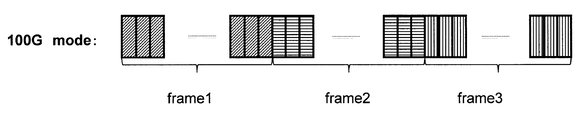
- FIG. 8 to FIG. 10 are diagrams showing frame states in the transmission path of the network system 1 including the switch 2 as an example of the embodiment.
- 8 is a diagram showing a 10G mode frame in a 100 Gbps transmission path
- FIG. 9 is a diagram showing a 100 G frame in a 100 Gbps transmission path
- FIG. 10 is a diagram in which 10 G frames and 100 G frames are mixed in a 100 Gbps transmission path. It is a figure which shows the example which transmits.
- each rectangle indicates a 10G frame, and a state (10G mode) in which a plurality of 10G frames are multiplexed and transferred in a 100 Gbps transmission path. That is, 10G frames are multiplexed and transferred to 100G.
- FIG. 9 shows a state (100G mode) in which a 100 G frame is transferred on a 100 Gbps transmission path. Each 100G frame has a data size corresponding to 10 10G frames. In this 100G mode, data is sent using 100% of the transmission capacity of a 100 Gbps transmission line.
- each rectangle represents data, and one rectangle represents one unit of data.
- One rectangle (data) has a data size of 8 bytes, for example.
- 10G mode data and 100G mode data cannot be mixed and transmitted. Therefore, as shown in FIG. 10, by transmitting the frame of the other mode after the transmission of the frame of one mode is completed, the 100G mode frame and the 10G mode frame are switched and transferred.
- FIG. 11 is a diagram illustrating a frame selection algorithm in mode 1 (100G priority) in the switch 2 as an example of the embodiment
- FIG. 12 is a diagram illustrating a frame selection algorithm in the mode 2 (10G priority).
- a 100G mode frame is transferred with priority over a 10G mode frame. That is, as shown in FIG. 11, in principle, if the number of 100G mode frames is greater than or equal to the first predetermined number (for example, one), the 10G mode frame is put in a transfer waiting state, the transfer is suppressed, and the 100G mode frame is transferred. .
- the first predetermined number for example, one
- the 10G mode frame is transferred.
- the 10G mode frame is also transferred when a predetermined number (eg, 10) or more of 10G mode frames are accumulated.
- the 10G mode frame is transferred with priority over the 100G mode frame. That is, as shown in FIG. 12, in principle, if there are more than a second predetermined number (for example, one) of 10G mode frames, the 100G mode frames are put in a transfer waiting state, the transfer is suppressed, and the 10G mode frames are transferred. .
- mode 1 and mode 2 are switched at a constant cycle. Continuing mode 1 or mode 2 may cause either 100 G mode frame or 10 G mode frame to stay excessively in switch 2. Therefore, by periodically switching between mode 1 and mode 2 at a constant cycle, it is possible to prevent either the 100G mode frame or the 10G mode frame from staying in the switch 2.
- Which of the modes 1 to 3 is adopted as the frame selection algorithm is registered in advance in the mode register 356 in the output port 30, for example, and the request selector 352 reads out the value of the mode register 356, and the modes 1 to 3 are selected. Select one of the following. Then, the request selector 352 selects a frame to be transmitted in the request buffer 353 according to the selected mode.
- the first and second predetermined numbers and the first and second predetermined times can be implemented with various modifications. Further, it is desirable to set a value for specifying the first and second predetermined numbers and the first and second predetermined times in a register or the like and to change the values.
- This example provides a method in which a 10G mode frame and a 100G mode frame can be output without much waiting. The algorithm for determining the frame to be output from the number of 10G mode frames and 100G mode frames will be described, and the individual number and algorithm are not limited.
- the first and second predetermined numbers setting a value obtained by dividing the maximum transfer rate in the switch chip 100 by the minimum transfer rate (maximum transfer rate / minimum transfer rate) can effectively use the bus without waste. It is thought that.
- FIG. 13 and FIG. 14 are diagrams showing the operation as the next-stage switch of the switch 2 as an example of the embodiment.
- the switch 2 shown in FIGS. 13 and 14 corresponds to the switch # 03 shown in FIG.
- the input port 20 and the output port 30 each operate as a 100 Gbps interface.
- FIGS. 13 and 14 only a part of the plurality of input ports 20 and output ports 30 are shown for convenience.
- the switch # 03 when the switch chip 100 outputs a 10G mode frame group input from one input port 20 at a transmission rate of 100 Gbps at a transmission rate of 100 Gbps from one output port 30, FIG. Thus, the input data group is transferred as it is by the CT method.
- the switch # 03 when the switch # 03 outputs 10G mode frames F1 to F6 input from one input port 20 at a transmission rate of 100 Gbps at three transmission ports 30 at a transmission rate of 100 Gbps, the switch # 03 As shown in FIG. 14, the chip 100 transfers back to the 10G mode frame at each output port 30.
- FIG. 15 is a diagram illustrating the operation of the switch 2 as an example of the embodiment. Note that the switch 2 illustrated in FIG. 15 corresponds to the switch # 05 illustrated in FIG. However, in the example shown in FIG. 15, it is assumed that each of the three output ports 30 of the switch 2 outputs at a transmission rate of 10 Gbps. In the switch # 05, the input port 20 operates as a 100 Gbps interface, and the plurality of output ports 30 each operate as a 10 Gbps interface. In FIG. 15, only a part of the plurality of input ports 20 and output ports 30 are shown for convenience.
- the switch chip 100 receives 10G mode frames F1 to F6 input at a transmission rate of 100 Gbps from one input port 20 from the three output ports 30 respectively. Output at the transmission speed.
- (B) Operation The processing of the switch chip 100 in the network system 1 as an example of the embodiment configured as described above will be described with reference to FIG.
- each input port 20 receives three 10G mode frames at a transmission rate of 100 Gbps and three 100G mode frames at a transmission rate of 100 Gbps.
- the received six frames are transmitted after determining the order of transmission at the output port 30 of the output destination and performing processing such as multiplexing.
- the frame parser 24 checks whether the frame received at 100 Gbps is a 100G mode frame or a 10G mode frame.
- the frame parser 24 uses, for example, a frame input to the input port 20 based on the interface speed determined at the time of link-up as a 100G mode frame. Or a 10G mode frame.
- the frame parser 24 determines whether the frame is a 100G mode frame or a 10G mode frame based on the data transmission rate information. You may judge.
- the frame parser 24 refers to the data transmission rate information included in the PR of the received frame, so that the frame is in the 100G mode. Whether it is a frame or a 10G mode frame can be determined. Since PR data is not necessary as original information, transmission to the inside of the chip is unnecessary, but the speed information is transmitted from the MAC 23 to the frame parser 24.
- the frame parser 24 recognizes the received frame as a 10G mode frame, only a portion where actual data exists is extracted and written to the shared memory 11 via the input buffer 25.
- data is continuously stored in the shared memory 11 via the input buffer 25.
- information such as a transmission destination necessary for transferring the data is sent to the frame / memory controller 12.
- the frame / memory controller 12 confirms the data and refers to the table 13 to determine from which output port 30 the data of the destination information is transmitted.
- the frame / memory controller 12 After determining the output port 30, the frame / memory controller 12 passes the information to the output port 30. Thereby, the output port 30 understands what data it should transmit.
- the output port 30 determines which of the 10G mode frame and the 100G mode frame is to be transmitted according to any one of the frame selection algorithms of modes 1 to 3, and transmits the frame according to this determination.
- the output port 30 receives information about a frame transmitted from the frame / memory controller 12.
- Information (request information) received from the frame / memory controller 12 is sequentially stored in the request buffer 353.
- the request selector 352 selects one of the modes 1 to 3 according to the set value of the mode register 356, and determines a request to be transmitted according to a frame selection algorithm corresponding to the selected mode.
- the request selector 352 and the request buffer 353 select the corresponding data, and extract the respective data from the shared memory 11 for each predetermined unit in order and multiplex them to the data buffer 354. Store. As a result, a mixed frame (see FIG. 8) is created in the data buffer 354.
- the timing for storing data in the data buffer 354 is adjusted using a known method such as a frame editor. Thereafter, the data is sent to the MAC 33 and sent by the known method via the PCS 32 and the PMA / PMD 31.
- the request selector 352 and the request buffer 353 sequentially connect the three 100G mode frames one by one (see FIG. 9), and transmit them to the MAC 33.
- the output port 30 if the data transmission rate information is not stored in the PR of the frame, the data transmission rate information is inserted into the PR of the frame in the MAC 33.
- the MAC 33 determines the data transmission rate information based on information from which input port 20 the frame is received, and sets it to PR.
- the input port 20 and the output port 30 are all described as having a speed of 100 Gbps.
- the present invention is not limited to this, and various modifications are made. be able to.
- the speeds of the input port 20 and the output port 30 may be appropriately controlled so as to match the configuration and setting. That is, a mixed frame is created at the output port 30 in accordance with the speed difference between the frame input to the input port 20 and the frame output from the output port 30.
- the switch chip 100 detects data reception by finding the PR of the input frame.
- the MAC 23 when the frame data is 100 Gbps, the data is transferred as it is.
- the data is thinned out to 1/10 and transferred within the switch chip 100.
- the data is stored in the width of the internal bus and transferred. That is, transfer is performed with the usage rate of the internal bus of the normal switch chip 100 being 1/10.
- the frame data is transferred to the shared memory 11.
- Data used for frame transfer such as DA is sent to the frame / memory controller 12.
- the frame / memory controller 12 determines an output port 30 to which data is transferred, and instructs writing to the shared memo 11. You are now ready to transfer data.
- the frame / memory controller 12 stores the data in the shared memory 11, it notifies the output buffer 30 of the request.
- the notified request is stored in the request buffer 353, and a request to be transmitted is determined by the request selector 352 and the timer 351 according to the frame selection algorithm described above.
- the determined requests are sequentially read from the shared memory 11 and stored in the data buffer 354. That is, the output port 30 reads data. At this time, since each input data is transferred to the output port 30 in the output port 30, many requests for output are accumulated in the output port 30 depending on the case.
- the output buffer 35 data is read from the shared memory 11 in accordance with an instruction from the request selector 352 and stored in the data buffer 354, thereby generating mixed data in the data buffer 354.
- the output port 30 when a 100G mode frame is output, one frame occupies the entire band.
- a 10G mode frame is transmitted, a maximum of 10 frames are multiplexed and transmitted. In other words, the 10G mode frame is read at a cycle 10 times that of reading the 100G mode frame and stored in the data buffer 354.
- the request selector 352 reads the value of a register (not shown) and selects any one of modes 1 to 3 according to the value of this register. Then, the request selector 352 selects a frame to be transmitted in the request buffer 353 according to the selected mode. The data stored in the data buffer 354 is transmitted to the MAC 33 as soon as a transmission port (not shown) is ready. At this time, when editing a frame, for example, setting data transmission speed information in the PR of the frame, the processing is performed using, for example, a frame editor.
- step S1 the request selector 352 refers to, for example, the request buffer 353 and determines whether there is a request to be transmitted. If there is no request (refer to the NO route in step S1), step S1 is repeated to wait for a request.
- step S5 If there is no 10G mode frame request (see YES route in step S4), in step S5, the oldest data in the 100G mode frame transfer request (100G request: 100Gbps Request) is transmitted to the MAC 33, and the process is performed. finish. On the other hand, if the 10G request exists as data to be transmitted (see NO route in step S4), then in step S6, there are one or more and 9 or less 10G requests, and one It is confirmed whether or not the above 100G request exists. That is, the operation is changed depending on the number of 10 requests and 100G requests.
- the request selector 352 selects the timer 351 in step S7. To check if it is running.
- the request selector 352 instructs the timer 351 to start timing in step S8. The timer 351 starts timing according to this instruction.
- step S7 If the timer 351 has already been started and time is being measured (see YES route in step S7), the request selector 352 exceeds the predetermined time in the time measured by the timer 351 in step S9 (see FIG. Check if the timer is over. If timer over is not detected (see NO route in step S9), in step S11, the oldest data in the 100G request is transmitted to the MAC 33, and the process ends.
- step S9 may be skipped and it may transfer to step S11 directly from step S8.
- step S10 the oldest data in the 10G request is transmitted to the MAC 33 in order. If the timer is over, a 10G mode frame is preferentially transmitted because the 10G request has been held for a long time. It is desirable that the value of the timer 351 can be set in a register in the switch chip that can be changed after hardware design. Thereafter, the process ends.
- step S6 when one or more and 9 or less 10G requests exist and the condition that one or more 100G requests exist (see the NO route in step S6), in step S12, it is confirmed whether there are 10 or more 10G requests and one or more 100G requests. If there are 10 or more 10G requests and one or more 100G requests (see YES route in step S12), either a 10G mode frame or a 100G mode frame is transmitted in step S13. Which frame is to be transmitted may be determined by hardware, or may be set by a register in the switch chip.
- step S12 if the condition that there are 10 or more 10G requests and one or more 100G requests is not satisfied (see the NO route in step S12), this is an abnormal state that is not possible. Therefore, in step S14, the request selector 352 records a flag indicating that an error has occurred in an error flag set in a register area (not shown) in the switch chip 100, and ends the processing.
- FIG. 17 is a flowchart (steps S1 to S5, S61, S7 to S9, S101, S111, S12 to S14) for explaining a frame transmission method in mode 2 by the output buffer 35 of the switch 2 as an example of the embodiment.
- the flowchart shown in FIG. 17 includes S101 and S111 instead of S10 and S11 in the flowchart shown in FIG.
- the description is abbreviate
- step S9 if timer over is not detected (see NO route in step S9), in step S111, the oldest data in the 10G request is transmitted to the MAC 33 in order, and the process is terminated. If a timer over is detected (see YES route in step S9), the oldest data in the 100G request is transmitted to the MAC 33 in step S101.
- the switch 2 performs data transfer by the CT method of sequentially outputting the received frame data without waiting for the output until all the data of the frame is completed. As a result, it is not necessary to perform a data store that causes an increase in latency, and low latency and high throughput can be realized.
- the time required for the data store required in the ST method can be reduced and the latency can be shortened. It is possible.
- the low-speed reception data from the plurality of input ports 20 is inserted into the gaps by mixing (multiplexing) the low-speed reception data input from the plurality of input ports 20.
- data can be transmitted continuously without a gap.
- the 100 Gbps frame uses 100% of the bandwidth of the 100 Gbps transmission path. Forward.
- a 10 Gbps frame is transferred utilizing a 10% bandwidth of a 100 Gbps transmission path. At 10 Gbps, only 10% of the bandwidth is used. Therefore, the data store that causes an increase in latency can be reduced by transferring the 10 Gbps frame with a maximum of 10 frames.
- the mixed frame is created by mixing (superposing) the frame data in a certain amount in the order of arrival in the output buffer 35.
- the frames when frames of a plurality of speeds are transferred in the switch 2, the frames can be efficiently transferred with low latency without lowering the throughput. This can be realized with lower latency while maintaining the above.
- the maximum transmission area that is the core of the network system 1, since the transfer is performed at the maximum speed of the switch chip 100, the setting of the network system 1 is simplified. Also, the same cable can be used in that area, and the cost for constructing the network system 1 can be reduced.
- FIG. 18 is a diagram illustrating a first modification of the network system 1 including the switch 2 as an example of the embodiment.
- the data transmission rate information of the field “PR” in the 10G mode frame and the 100G mode frame is set in each server 3. That is, the server 3 also mixes speeds of 100 Gbps and 10 Gbps.
- the maximum speed transmission area a in the network system 1 can be widened, whereby the data flow in the network system 1 can be further optimized.
- An output port (not shown) of the server (data output device) 3 has the same function as the output port 30 of the switch chip 100 described above.
- the server 3 generates a multiplexed frame by multiplexing frames of the first transmission rate (for example, 10 Gbps), and uses the multiplexed frame as a second transmission rate that is faster than the first transmission rate.
- the data can be output from a communication path that can be transmitted at (eg, 100 Gbps).
- FIG. 19 is a diagram illustrating a second modification of the network system 1 including the switch 2 as an example of the embodiment.
- the case where all the ports 20 and 30 have a speed of 100 G has been described.
- the speeds of the input port and the output port may be controlled to match the configuration and setting.
- the network system 1 shown in FIG. 19 includes a switch_0 (SW_0) instead of the switch # 04 in the network system 1 shown in FIG.
- the switch_0 supports only 10 Gbps, which is a low transmission rate, and includes a switch chip that does not support a transmission rate of 100 Gbps. In this way, in the network system 1, it is possible to mix switches 2 that support only 10 Gbps, which is a low transmission rate.
- the switch_0 is excluded from the maximum speed transmission area a, and the boundary with the maximum speed transmission area a is between SW_O and the SW group.
- the configuration of the network system 1 is not limited to the configuration illustrated in FIGS. 2, 18 and 19, and can be implemented with appropriate modifications.
- the number of servers 3, edge switches 2, and next-stage switches 2 can be changed as appropriate.
- the two types of transmission rate frames ie, the 10G mode frame and the 100G mode frame are exemplified, but the present invention is not limited to this. That is, it may be a frame with a transmission rate other than 10G or 100G, or a mixture of frames with three or more types of transmission rates.
- the request buffer 353 is provided in the output buffer 35, but is not limited thereto, and may be in the frame / memory controller 12, for example.
- the processor and the storage device are provided, and the processor executes the program stored in the storage device, thereby realizing the functions as the request selector 352 and the timer 351 described above. May be.
Abstract
A data transfer device is provided with a mixed data creation unit (35) for mixing received data input from a plurality of first communication paths and creating mixed data when the data transmission speed of the received data input from the plurality of first communication paths is lower than the data transmission performance value of a second communication path, and an output unit (35) for outputting the mixed data created by the mixed data creation unit (35) to the second communication path. Thereby, it is possible to enhance data transfer efficiency.
Description
本発明は、データ転送装置,データ出力装置,データ転送方法及びデータ出力方法に関する。
The present invention relates to a data transfer device, a data output device, a data transfer method, and a data output method.
ネットワークシステムにおいて、近年、高速なインタフェースが次々と開発されており、又、高速化への要求は増々高まる一方である。それにより、今後は、新旧のシステム機器が混在するシステムが多くなり、システム機器においては、複数の伝送速度をサポートするデータ転送装置が望まれる。
例えば、イーサネット(登録商標)では、近年100Gbpsの伝送速度を持つ製品が発売されている。これにより、イーサネットスイッチ等のデータ転送装置では、1Gbps,10Gbps,40Gbps及び100Gbps等の複数のデータ伝送速度をサポートすることが期待される。以下、データ転送装置がイーサネットスイッチ(単にスイッチという)の例について示す。 In recent years, high-speed interfaces have been developed one after another in network systems, and the demand for higher speed is increasing. As a result, in the future, a system in which old and new system devices are mixed will increase, and a data transfer device that supports a plurality of transmission speeds is desired in the system devices.
For example, in Ethernet (registered trademark), products having a transmission rate of 100 Gbps have recently been released. As a result, data transfer devices such as Ethernet switches are expected to support multiple data transmission rates such as 1 Gbps, 10 Gbps, 40 Gbps, and 100 Gbps. Hereinafter, an example in which the data transfer apparatus is an Ethernet switch (simply referred to as a switch) will be described.
図20は従来のネットワークシステムの構成例を示す図である。この図20に示すネットワークシステムは、複数のサーバ(Server)#00,#01,#10~#14と、複数のスイッチ(SW)#1~#5とを備えている。
この図20に示すネットワークシステムにおいて、例えば、サーバ#00からサーバ#10にデータを送信する場合に、データ(フレーム)は、サーバ#00→SW#1→SW#2→SW#4→サーバ#10のルートで伝送される。この伝送ルートにおいては、サーバ#00からサーバ#10までを接続する各伝送路のスループット(データ伝送性能)はいずれも10Gbpsであり、各SW#1,#2,#4においては、それぞれ単純なデータ転送が行なわれる。 FIG. 20 is a diagram illustrating a configuration example of a conventional network system. The network system shown in FIG. 20 includes a plurality of servers (Server) # 00, # 01, # 10 to # 14, and a plurality of switches (SW) # 1 to # 5.
In the network system shown in FIG. 20, for example, when data is transmitted fromserver # 00 to server # 10, the data (frame) is server # 00 → SW # 1 → SW # 2 → SW # 4 → server #. 10 routes are transmitted. In this transmission route, the throughput (data transmission performance) of each transmission path connecting server # 00 to server # 10 is 10 Gbps, and each SW # 1, # 2, # 4 is simple. Data transfer is performed.
この図20に示すネットワークシステムにおいて、例えば、サーバ#00からサーバ#10にデータを送信する場合に、データ(フレーム)は、サーバ#00→SW#1→SW#2→SW#4→サーバ#10のルートで伝送される。この伝送ルートにおいては、サーバ#00からサーバ#10までを接続する各伝送路のスループット(データ伝送性能)はいずれも10Gbpsであり、各SW#1,#2,#4においては、それぞれ単純なデータ転送が行なわれる。 FIG. 20 is a diagram illustrating a configuration example of a conventional network system. The network system shown in FIG. 20 includes a plurality of servers (Server) # 00, # 01, # 10 to # 14, and a plurality of switches (SW) # 1 to # 5.
In the network system shown in FIG. 20, for example, when data is transmitted from
一方、サーバ#00からサーバ#14にデータを送信する場合には、データは、サーバ#00→SW#1→SW#3→SW#5→サーバ#14のルートで伝送される。この伝送ルートにおいては、サーバ#00とSW#1との間の伝送路のスループットは10Gbpsであり、SW#1からサーバ#14までの各伝送路のスループットは100Gbpsである。従って、SW#1では、10Gbpsのフレームが100Gbpsのフレームに変換される。
On the other hand, when data is transmitted from the server # 00 to the server # 14, the data is transmitted through the route of the server # 00 → SW # 1 → SW # 3 → SW # 5 → server # 14. In this transmission route, the throughput of the transmission path between server # 00 and SW # 1 is 10 Gbps, and the throughput of each transmission path from SW # 1 to server # 14 is 100 Gbps. Therefore, in SW # 1, a 10 Gbps frame is converted into a 100 Gbps frame.
なお、図20中では、便宜上、各機器間を転送されるデータを矢印で示している。機器間の伝送路上で100Gbpsのフレームを伝送する場合には、4レーンや10レーン等の複数レーンを使用して伝送する方式もある。
図21は従来のデータ中継装置におけるデータ転送を模式的に示す図、図22はその転送手法を示す図である。 In FIG. 20, data transferred between the devices is indicated by arrows for convenience. When a 100 Gbps frame is transmitted on a transmission path between devices, there is a method of transmitting using a plurality of lanes such as 4 lanes and 10 lanes.
FIG. 21 is a diagram schematically showing data transfer in a conventional data relay device, and FIG. 22 is a diagram showing the transfer method.
スイッチは、入力されたフレームを所望のあて先に対応する出力(転送)する機能を有するスイッチチップを備える。
図21中において、斜線を付した矩形はそれぞれデータを示しており、一つの矩形が1単位のデータを示している。一つの矩形(データ)は、例えば、8バイトのデータサイズを有する。データを複数集めたものをフレームという。 The switch includes a switch chip having a function of outputting (transferring) an input frame corresponding to a desired destination.
In FIG. 21, each shaded rectangle represents data, and one rectangle represents one unit of data. One rectangle (data) has a data size of 8 bytes, for example. A collection of multiple data is called a frame.
また、図21に示すスイッチチップは10Gbps及び100Gbpsの各フレームが入力可能に構成されるとともに、10Gbps及び100Gbpsの各フレームを出力可能に構成されている。すなわち、10Gbps及び100Gbpsの入力と、10Gbps及び100Gbpsの出力との全組み合わせでフレームの転送を行なうことができる。
図21中においては、スイッチチップにおける入出力のフレーム速度の組み合わせによる内部動作を点線矢印で示している。 The switch chip shown in FIG. 21 is configured to be able to input 10 Gbps and 100 Gbps frames and to be able to output 10 Gbps and 100 Gbps frames. In other words, frame transfer can be performed with all combinations of 10 Gbps and 100 Gbps inputs and 10 Gbps and 100 Gbps outputs.
In FIG. 21, the internal operation by the combination of input and output frame speeds in the switch chip is indicated by dotted arrows.
このスイッチチップにおいては、CT(Cut Through)方式とS&F(Store & Forward)方式とのいずれかの方式でフレームの転送が行なわれる。
具体的には、同一速度と速い速度から遅い速度に転送する場合は、CT方式でデータ転送を行ない、遅い速度から速い速度で転送する場合は、そのフレームデータに連続して送信できるようにS&F方式で転送する。すなわち、図22に示すように、10Gbpsで入力されたフレームを100Gbpsで出力する場合にはS&F方式を用い、それ以外の組み合わせにはCT方式を用いる。 In this switch chip, a frame is transferred by either a CT (Cut Through) method or an S & F (Store & Forward) method.
Specifically, when transferring from the same speed and a fast speed to a slow speed, data transfer is performed using the CT method, and when transferring from a slow speed to a fast speed, S & F is performed so that the frame data can be transmitted continuously. Transfer using the method. That is, as shown in FIG. 22, the S & F method is used when a frame input at 10 Gbps is output at 100 Gbps, and the CT method is used for other combinations.
ここで、CT方式は、入力されたフレームのデータを全て読み込む前に、次々と受信したデータを転送する方式である。出力データの伝送速度が入力データの伝送速度と同等かそれ以下のため、CT方式で転送してもスイッチチップ内でデータが枯渇して出力フレームが断絶されることがなく、すべてのデータが連続して送出される。
一方、S&F方式は、受信したフレームのすべてのデータを、一度スイッチチップ内部のバッファに格納した後に転送する方式である。10Gbpsで入力されたフレームを100Gbpsで出力する場合は、出力データの伝送速度が入力データに対して速いので、CT方式で出力すると出力するデータがスイッチ内部で枯渇してしまう。すなわち、データを連続して送出できない。 Here, the CT method is a method of transferring received data one after another before reading all the data of the input frame. Since the output data transmission rate is equal to or less than the input data transmission rate, even if the data is transferred by CT, the data is not exhausted in the switch chip and the output frame is not interrupted. And sent out.
On the other hand, the S & F method is a method in which all data of a received frame is once stored in a buffer inside the switch chip and then transferred. When a frame input at 10 Gbps is output at 100 Gbps, the output data transmission speed is faster than that of the input data. Therefore, when the CT method is used for output, the output data is exhausted inside the switch. That is, data cannot be sent continuously.
一般に、CT方式はS&F方式よりも少ないレイテンシィで転送することが可能である。そのため、性能の面では、CT方式の方がS&F方式よりも優れていると言える。又、CT方式でデータ転送を行なうことができる場合には、S&F方式でも行なうことができる。フレームのチェック等の処理を行なうために、スイッチチップ内に一度バッファするように、あえてS&F方式で転送する場合もある。
Generally, the CT method can be transferred with less latency than the S & F method. Therefore, it can be said that the CT method is superior to the S & F method in terms of performance. Further, when data transfer can be performed by the CT method, it can also be performed by the S & F method. In order to perform processing such as frame checking, there is a case where the data is transferred by the S & F method so as to be buffered once in the switch chip.
このようなスイッチチップにおいて重要とされる性能スペックは、スループットとレイテンシィである。ここでいうスループットとは、そのスイッチチップが転送できる単位時間当たりのデータ量を指し、このスループットの値が大きければ大きいほど大量のデータを処理できるということになる。レイテンシィとは、スイッチチップをデータが通過するのに要する時間を示す。このレイテンシィの値が小さければ小さいほど、そのデータの転送処理が速いということになる。
特開平6-97904号公報
The performance specifications that are important in such a switch chip are throughput and latency. Throughput here refers to the amount of data per unit time that can be transferred by the switch chip, and the larger the throughput value, the greater the amount of data that can be processed. Latency refers to the time required for data to pass through the switch chip. The smaller the latency value, the faster the data transfer process.
JP-A-6-97904
さて、上述した従来のデータ転送装置においては、10Gbpsの伝送路で受信したフレームを100Gbpsの伝送路に転送する場合にS&F方式が用いられる。S&F方式においては、受信したフレームをスイッチチップ内に一度バッファリングした後に、100Gbpsの速度で転送するので、スイッチチップでのレイテンシィが大きくなる。
例えば、データサイズが9KByte程度の大きなフレームを10Gbpsの伝送路で受信して転送する場合には、フレームをスイッチチップ内のバッファに溜めるために、最低でも7200nsもかかると試算される。一方で、CT方式を採用した場合にスイッチチップを通過するレイテンシィは数百ns程度である。 In the conventional data transfer apparatus described above, the S & F method is used when a frame received via a 10 Gbps transmission path is transferred to a 100 Gbps transmission path. In the S & F method, the received frame is buffered once in the switch chip and then transferred at a rate of 100 Gbps, so that the latency at the switch chip increases.
For example, when a large frame having a data size of about 9 KByte is received and transferred through a 10 Gbps transmission path, it is estimated that it takes at least 7200 ns to store the frame in a buffer in the switch chip. On the other hand, when the CT method is adopted, the latency through the switch chip is about several hundred ns.
従って、従来のデータ転送装置においては、S&F方式を採用することによりスイッチチップ内においてレイテンシィが増加し、ネットワークシステムの伝送性能を低下させるという課題がある。
また、出力側において100Gbpsの伝送路を10Gbpsのデータしか流さないようにすることによりCT方式で送信することも考えられる。しかしながら、この場合には、100Gbpsの伝送性能を有する出力側の伝送路において帯域の10%しか使用しないことになり、高速なインタフェースの性能を有効に用いることができない。 Therefore, in the conventional data transfer apparatus, there is a problem in that the latency increases in the switch chip and the transmission performance of the network system is lowered by adopting the S & F method.
It is also conceivable to transmit by the CT method by allowing only 10 Gbps data to flow through the 100 Gbps transmission path on the output side. However, in this case, only 10% of the bandwidth is used in the transmission line on the output side having a transmission performance of 100 Gbps, and the high-speed interface performance cannot be used effectively.
このように、従来のデータ転送装置においては、スイッチチップにおいて異なる伝送速度の転送を処理する場合に、効率よくデータ転送を行なうことができないという課題がある。
1つの側面では、本発明は、データ転送効率を向上できるようにすることを目的とする。 As described above, the conventional data transfer apparatus has a problem that data transfer cannot be performed efficiently when transfer at different transmission rates is processed in the switch chip.
In one aspect, an object of the present invention is to improve data transfer efficiency.
なお、前記目的に限らず、後述する発明を実施するための形態に示す各構成により導かれる作用効果であって、従来の技術によっては得られない作用効果を奏することも本発明の他の目的の1つとして位置付けることができる。
In addition, the present invention is not limited to the above-described object, and other effects of the present invention can be achieved by the functions and effects derived from the respective configurations shown in the embodiments for carrying out the invention which will be described later. It can be positioned as one of
このため、このデータ転送装置は、複数の第1通信路と、1つ以上の第2通信路との間でデータの転送を行なうデータ転送装置において、前記複数の第1通信路のそれぞれから入力された受信データのデータ伝送速度が前記第2通信路のデータ伝送性能値よりも低い場合に、前記複数の第1通信路のそれぞれから入力される受信データを混合して混合データを作成する混合データ作成部と、前記混合データ作成部により作成された前記混合データを前記第2通信路に出力する出力部とを備える。
For this reason, this data transfer device is a data transfer device that transfers data between a plurality of first communication paths and one or more second communication paths, and inputs from each of the plurality of first communication paths. Mixed to create mixed data by mixing the received data input from each of the plurality of first communication channels when the data transmission rate of the received data is lower than the data transmission performance value of the second communication channel A data creation unit; and an output unit that outputs the mixed data created by the mixed data creation unit to the second communication path.
また、このデータ転送方法は、複数の第1通信路と、1つ以上の第2通信路との間でデータの転送を行なうデータ転送装置におけるデータ転送方法であって、前記複数の第1通信路のそれぞれから入力された受信データのデータ伝送速度が前記第2通信路のデータ伝送性能値よりも低い場合に、前記複数の第1通信路のそれぞれから入力される受信データを混合して混合データを作成し、作成された前記混合データを前記第2通信路に出力する。
The data transfer method is a data transfer method in a data transfer device that transfers data between a plurality of first communication paths and one or more second communication paths, wherein the plurality of first communication paths When the data transmission rate of the received data input from each of the channels is lower than the data transmission performance value of the second communication channel, the received data input from each of the plurality of first communication channels is mixed and mixed Data is created, and the created mixed data is output to the second communication path.
また、このデータ出力装置は、第1の伝送速度の第1のフレームと、前記第1の伝送速度よりも速い第2の伝送速度の第2のフレームとを伝送可能な通信路にデータ出力を行なうデータ出力装置であって、前記第2の伝送速度を前記第1の伝送速度で除算して求められる数の前記第1のフレームを多重化して多重化フレームを作成する多重化処理部と、前記多重化処理部により作成された前記多重化フレームを前記通信路に出力する出力部とを備える。
The data output device outputs data to a communication path capable of transmitting a first frame having a first transmission rate and a second frame having a second transmission rate higher than the first transmission rate. A data output device for performing a multiplexing processing unit that multiplexes the number of the first frames determined by dividing the second transmission rate by the first transmission rate to create a multiplexed frame; An output unit for outputting the multiplexed frame created by the multiplexing processing unit to the communication path.
一実施形態によれば、データ転送効率を向上させることができる。
According to one embodiment, data transfer efficiency can be improved.
以下、図面を参照して本データ転送装置,データ出力装置,データ転送方法及びデータ出力方法に係る実施の形態を説明する。ただし、以下に示す実施形態はあくまでも例示に過ぎず、実施形態で明示しない種々の変形例や技術の適用を排除する意図はない。すなわち、本実施形態を、その趣旨を逸脱しない範囲で種々変形(実施形態及び各変形例を組み合わせる等)して実施することができる。又、各図は、図中に示す構成要素のみを備えるという趣旨ではなく、他の機能等を含むことができる。
Hereinafter, embodiments of the data transfer device, the data output device, the data transfer method, and the data output method will be described with reference to the drawings. However, the embodiment described below is merely an example, and there is no intention to exclude application of various modifications and techniques not explicitly described in the embodiment. In other words, the present embodiment can be implemented with various modifications (combining the embodiments and modifications) without departing from the spirit of the present embodiment. Each figure is not intended to include only the components shown in the figure, and may include other functions.
(A)構成
図1は実施形態の一例としてのスイッチ(データ転送装置,データ出力装置)2に備えられるスイッチチップ(データ転送回路)100の構成を模式的に示す図、図2はそのスイッチ2を備えたスイッチを有するネットワークシステム1の構成を例示する図である。
図2に例示するネットワークシステム1は、複数のサーバ(Server)3と、複数のスイッチ(SW)2とを備えている。なお、図2に示す例では、サーバ#00,#01,#10~#14の7つのサーバ3と、スイッチ#01~#05の5つのスイッチ2とを備えている。 (A) Configuration FIG. 1 is a diagram schematically showing a configuration of a switch chip (data transfer circuit) 100 provided in a switch (data transfer device, data output device) 2 as an example of an embodiment, and FIG. It is a figure which illustrates the structure of thenetwork system 1 which has a switch provided with.
Thenetwork system 1 illustrated in FIG. 2 includes a plurality of servers 3 and a plurality of switches (SW) 2. In the example shown in FIG. 2, seven servers 3 of servers # 00, # 01, and # 10 to # 14 and five switches 2 of switches # 01 to # 05 are provided.
図1は実施形態の一例としてのスイッチ(データ転送装置,データ出力装置)2に備えられるスイッチチップ(データ転送回路)100の構成を模式的に示す図、図2はそのスイッチ2を備えたスイッチを有するネットワークシステム1の構成を例示する図である。
図2に例示するネットワークシステム1は、複数のサーバ(Server)3と、複数のスイッチ(SW)2とを備えている。なお、図2に示す例では、サーバ#00,#01,#10~#14の7つのサーバ3と、スイッチ#01~#05の5つのスイッチ2とを備えている。 (A) Configuration FIG. 1 is a diagram schematically showing a configuration of a switch chip (data transfer circuit) 100 provided in a switch (data transfer device, data output device) 2 as an example of an embodiment, and FIG. It is a figure which illustrates the structure of the
The
以下、サーバを示す場合に、複数のサーバのうち1つを特定する必要があるときには符号#00,#01,#10~#14を付して示すが、任意のサーバを指すときには符号3を用いる。同様に、以下、スイッチを示す場合に、複数のスイッチのうち1つを特定する必要があるときには符号#01~#05を付して示すが、任意のスイッチを指すときには符号2を用いる。
Hereinafter, in the case of indicating a server, when it is necessary to specify one of a plurality of servers, reference numerals # 00, # 01, and # 10 to # 14 are attached. Use. Similarly, in the following, when a switch is indicated, reference numeral # 01 to # 05 are attached when it is necessary to specify one of a plurality of switches, but reference numeral 2 is used to indicate any switch.
ネットワークシステム1において、スイッチ2は、入力されたデータをフレーム転送方式で転送する。各スイッチ2は、複数の伝送速度でのデータの入出力をサポートしており、例えば、1Gpbs,10Gbps,40Gbps及び100Gbpsの各伝送速度でのデータ入力及びデータ出力を可能としている。
以下、本実施形態においては、便宜上、10Gbpsの伝送速度(第1の伝送速度)で伝送されるフレーム(第1のフレーム)と100Gbpsの伝送速度(第2の伝送速度)で伝送されるフレーム(第2のフレーム)との2種類の伝送速度のフレームが混在する例について示す。又、100Gbpsを混在する速度の最高速度(最高伝送速度)として考える。つまり、ネットワークシステム1におけるデータ転送速度の最高値が100Gbpsであるものとする。 In thenetwork system 1, the switch 2 transfers the input data by the frame transfer method. Each switch 2 supports data input / output at a plurality of transmission rates, and enables data input and data output at each transmission rate of 1 Gpbs, 10 Gbps, 40 Gbps, and 100 Gbps, for example.
Hereinafter, in this embodiment, for convenience, a frame (first frame) transmitted at a transmission rate of 10 Gbps (first transmission rate) and a frame (first transmission rate) transmitted at a transmission rate of 100 Gbps (second transmission rate) ( An example in which frames of two types of transmission rates (second frame) are mixed is shown. Also, consider the maximum speed (maximum transmission speed) of 100 Gbps. That is, the maximum value of the data transfer rate in thenetwork system 1 is 100 Gbps.
以下、本実施形態においては、便宜上、10Gbpsの伝送速度(第1の伝送速度)で伝送されるフレーム(第1のフレーム)と100Gbpsの伝送速度(第2の伝送速度)で伝送されるフレーム(第2のフレーム)との2種類の伝送速度のフレームが混在する例について示す。又、100Gbpsを混在する速度の最高速度(最高伝送速度)として考える。つまり、ネットワークシステム1におけるデータ転送速度の最高値が100Gbpsであるものとする。 In the
Hereinafter, in this embodiment, for convenience, a frame (first frame) transmitted at a transmission rate of 10 Gbps (first transmission rate) and a frame (first transmission rate) transmitted at a transmission rate of 100 Gbps (second transmission rate) ( An example in which frames of two types of transmission rates (second frame) are mixed is shown. Also, consider the maximum speed (maximum transmission speed) of 100 Gbps. That is, the maximum value of the data transfer rate in the
なお、ネットワークシステム1において、100Gbpsと10Gbpsとの速度の混在に限定されるものではなく、種々変形して実施することができるが、説明の便宜上、わかりやすいよう具体的な速度として、100Gbpsと10Gbpsとを用いて説明する。
以下、10Gbpsの伝送速度で伝送されるデータを単に10Gbpsのデータもしくは10Gのフレームといいう。同様に、100Gbpsの伝送速度で伝送されるデータを単に100Gbpsのデータもしくは100Gのフレームという。 Note that thenetwork system 1 is not limited to the mixed speed of 100 Gbps and 10 Gbps, but can be implemented with various modifications. For convenience of explanation, the specific speed is 100 Gbps and 10 Gbps for easy understanding. Will be described.
Hereinafter, data transmitted at a transmission rate of 10 Gbps is simply referred to as 10 Gbps data or 10 G frame. Similarly, data transmitted at a transmission rate of 100 Gbps is simply referred to as 100 Gbps data or 100 G frame.
以下、10Gbpsの伝送速度で伝送されるデータを単に10Gbpsのデータもしくは10Gのフレームといいう。同様に、100Gbpsの伝送速度で伝送されるデータを単に100Gbpsのデータもしくは100Gのフレームという。 Note that the
Hereinafter, data transmitted at a transmission rate of 10 Gbps is simply referred to as 10 Gbps data or 10 G frame. Similarly, data transmitted at a transmission rate of 100 Gbps is simply referred to as 100 Gbps data or 100 G frame.
本実施形態においては、図2に示すネットワークシステム1において、サーバ#00,#01から送信されたデータ(フレーム)が、複数のスイッチ2を介してサーバ#10~#14のいずれかに転送される例について示す。図2に示すネットワークシステム1において、図中の左側、すなわちサーバ#00,#01側を上流側といい、図中の右側、すなわちサーバ#10~#14側を下流側という場合がある。
In the present embodiment, in the network system 1 shown in FIG. 2, data (frames) transmitted from the servers # 00 and # 01 are transferred to any of the servers # 10 to # 14 via the plurality of switches 2. An example is shown. In the network system 1 shown in FIG. 2, the left side in the figure, that is, the servers # 00 and # 01 side may be referred to as the upstream side, and the right side in the figure, that is, the servers # 10 to # 14 side may be referred to as the downstream side.
スイッチ#01にはサーバ#00,#01及びスイッチ#02,#03が接続されている。スイッチ#02にはスイッチ#01,#04が、又、スイッチ#03にはスイッチ#01,#05が、それぞれ接続されている。スイッチ#04にはサーバ#10,#11及びスイッチ#02が接続されている。スイッチ#05にはサーバ#12,#13,#14及びスイッチ#03が接続されている。
The servers # 00 and # 01 and the switches # 02 and # 03 are connected to the switch # 01. Switches # 01 and # 04 are connected to the switch # 02, and switches # 01 and # 05 are connected to the switch # 03, respectively. Servers # 10 and # 11 and switch # 02 are connected to switch # 04. Servers # 12, # 13, # 14 and switch # 03 are connected to switch # 05.
以下、ネットワークシステム1に備えられているスイッチ2のうち、サーバ3が接続されているスイッチ2をエッジスイッチ2という場合がある。又、スイッチ2間に配置され、他のスイッチ2を介してサーバ3に接続されるスイッチ2を次段スイッチ2という場合がある。図2に示す例においては、スイッチ#01,#04,#05がエッジスイッチ2であり、スイッチ#02,#03が次段スイッチ2である。
Hereinafter, among the switches 2 provided in the network system 1, the switch 2 to which the server 3 is connected may be referred to as an edge switch 2. Further, the switch 2 arranged between the switches 2 and connected to the server 3 via another switch 2 may be referred to as a next-stage switch 2. In the example shown in FIG. 2, the switches # 01, # 04, and # 05 are the edge switches 2, and the switches # 02 and # 03 are the next stage switches 2.
また、図2に示す例において、サーバ#00,#10,#12,#13のインタフェースがサポートしているデータ転送速度の最高値がそれぞれ10Gbpsであり、サーバ#01,#11,#14のインタフェースがサポートしているデータ転送速度の最高値がそれぞれ100Gbpsである。
サーバ#00とスイッチ#01との間、スイッチ#01とスイッチ#02との間、スイッチ#04とサーバ#10との間、スイッチ#05とサーバ#12との間、及びスイッチ#05とサーバ#13との間の各伝送路のスループットは10Gbpsである。 Further, in the example shown in FIG. 2, the maximum values of the data transfer rates supported by the interfaces of theservers # 00, # 10, # 12, and # 13 are 10 Gbps, respectively, and the servers # 01, # 11, and # 14 The maximum data transfer rate supported by the interface is 100 Gbps each.
Betweenserver # 00 and switch # 01, between switch # 01 and switch # 02, between switch # 04 and server # 10, between switch # 05 and server # 12, and between switch # 05 and server The throughput of each transmission line with # 13 is 10 Gbps.
サーバ#00とスイッチ#01との間、スイッチ#01とスイッチ#02との間、スイッチ#04とサーバ#10との間、スイッチ#05とサーバ#12との間、及びスイッチ#05とサーバ#13との間の各伝送路のスループットは10Gbpsである。 Further, in the example shown in FIG. 2, the maximum values of the data transfer rates supported by the interfaces of the
Between
一方、サーバ#01とスイッチ#01との間、スイッチ#01とスイッチ#03との間、スイッチ#02とスイッチ#04との間、スイッチ#03とスイッチ#05との間、スイッチ#04とサーバ#11との間、及びスイッチ#05とサーバ#14との間の各伝送路のスループットは100Gbpsである。これらのスループットが100Gbpsの伝送路は100Gbpsの設定で使用されるものとする。
On the other hand, between server # 01 and switch # 01, between switch # 01 and switch # 03, between switch # 02 and switch # 04, between switch # 03 and switch # 05, and switch # 04 The throughput of each transmission path between the server # 11 and between the switch # 05 and the server # 14 is 100 Gbps. These transmission paths with a throughput of 100 Gbps are used with a setting of 100 Gbps.
図2に示すネットワークシステム1において、スループット100Gbpsの範囲(領域)を最高速度伝送領域といい、図2中においては、点線で環囲し、符号aを付して示す。
なお、各スイッチ2は同様の構成を備えており、それぞれ図1に示すスイッチチップ100を備える。すなわち、スイッチチップ100の種々の設定により、各スイッチ2としての機能がそれぞれ実現される。 In thenetwork system 1 shown in FIG. 2, a range (area) with a throughput of 100 Gbps is referred to as a maximum speed transmission area, and is surrounded by a dotted line and indicated by a symbol a in FIG.
Eachswitch 2 has the same configuration, and includes the switch chip 100 shown in FIG. That is, the function as each switch 2 is realized by various settings of the switch chip 100.
なお、各スイッチ2は同様の構成を備えており、それぞれ図1に示すスイッチチップ100を備える。すなわち、スイッチチップ100の種々の設定により、各スイッチ2としての機能がそれぞれ実現される。 In the
Each
例えば、エッジスイッチ#01,#04,#05には、スイッチ群で構成されたネットワークシステム1におけるエッジ部の設定が行なわれ、次段スイッチ#02,#03には、システム内他のスイッチのスイッチチップ100を接続するための設定が行なわれる。
具体的には、スイッチ#01,#04,#05においては、エッジ向け、すなわち、サーバ3に接続される側(サーバ側,上流側)のポートは、接続されたサーバ3のインタフェースがサポートしている速度に合わせて設定される。又、スイッチ#01,#04,#05における他のスイッチ2と接続される側の各ポート(スイッチチップ側,下流側)は、本ネットワークシステム1の仕様上の上限である100Gbps固定となるよう設定される。 For example, the edge switches # 01, # 04, and # 05 are set for the edge portion in thenetwork system 1 configured by a switch group, and the next-stage switches # 02 and # 03 are set for other switches in the system. Settings for connecting the switch chip 100 are performed.
Specifically, in theswitches # 01, # 04, and # 05, the ports for the edge, that is, the ports connected to the server 3 (server side and upstream side) are supported by the interface of the connected server 3. It is set according to the speed. In addition, each port (switch chip side, downstream side) connected to the other switch 2 in the switches # 01, # 04, and # 05 is fixed to 100 Gbps which is the upper limit in the specification of the network system 1. Is set.
具体的には、スイッチ#01,#04,#05においては、エッジ向け、すなわち、サーバ3に接続される側(サーバ側,上流側)のポートは、接続されたサーバ3のインタフェースがサポートしている速度に合わせて設定される。又、スイッチ#01,#04,#05における他のスイッチ2と接続される側の各ポート(スイッチチップ側,下流側)は、本ネットワークシステム1の仕様上の上限である100Gbps固定となるよう設定される。 For example, the edge switches # 01, # 04, and # 05 are set for the edge portion in the
Specifically, in the
一方、スイッチ#02,#03においては、サーバ#00,#01側(サーバ側,上流側)のポートは、スイッチ#01を介して接続されるサーバ3のインタフェースがサポートしている速度に合わせてそれぞれ設定される例で示す。スイッチ#02,#03のスイッチチップ側(下流側)は、本ネットワークシステム1の仕様上の上限である100Gbps固定となるよう設定される。
On the other hand, in the switches # 02 and # 03, the ports on the server # 00 and # 01 side (server side and upstream side) match the speed supported by the interface of the server 3 connected via the switch # 01. Are shown as examples. The switch chip side (downstream side) of the switches # 02 and # 03 is set to be fixed at 100 Gbps, which is the upper limit in the specifications of the network system 1.
最高速度伝送領域aに接続されるスイッチ2の各出力ポート30は、仕様上の上限である100Gbps固定となるよう設定される。
図3及び図4はそれぞれ実施形態の一例としてのスイッチ2を備えるネットワークシステム1において転送されるフレームの構成を例示する図であり、図3は10Gモードのフレームを例示する図、図4は100Gモードのフレームを例示する図である。 Eachoutput port 30 of the switch 2 connected to the maximum speed transmission area a is set to be fixed at 100 Gbps, which is the upper limit in the specification.
FIGS. 3 and 4 are diagrams illustrating the configuration of a frame transferred in thenetwork system 1 including the switch 2 as an example of the embodiment. FIG. 3 illustrates a 10G mode frame, and FIG. It is a figure which illustrates the frame of a mode.
図3及び図4はそれぞれ実施形態の一例としてのスイッチ2を備えるネットワークシステム1において転送されるフレームの構成を例示する図であり、図3は10Gモードのフレームを例示する図、図4は100Gモードのフレームを例示する図である。 Each
FIGS. 3 and 4 are diagrams illustrating the configuration of a frame transferred in the
本ストレージシステム1においては、これらの図3や図4に示すフレームが転送される。なお、図3及び図4中において、左側がフレームの先頭であり、右側がフレームの後尾である。
10Gモードのフレーム(10Gモードフレーム)は、10Gbpsの伝送路を通過させるべく作成されたフレームである。又、100Gモードのフレーム(100Gモードフレーム)は、100Gbpsの伝送路を通過させるべく作成されたフレームである。 In thepresent storage system 1, the frames shown in FIGS. 3 and 4 are transferred. In FIGS. 3 and 4, the left side is the head of the frame, and the right side is the tail of the frame.
A 10G mode frame (10G mode frame) is a frame created to pass through a 10 Gbps transmission path. A 100G mode frame (100G mode frame) is a frame created to pass through a 100 Gbps transmission path.
10Gモードのフレーム(10Gモードフレーム)は、10Gbpsの伝送路を通過させるべく作成されたフレームである。又、100Gモードのフレーム(100Gモードフレーム)は、100Gbpsの伝送路を通過させるべく作成されたフレームである。 In the
A 10G mode frame (10G mode frame) is a frame created to pass through a 10 Gbps transmission path. A 100G mode frame (100G mode frame) is a frame created to pass through a 100 Gbps transmission path.
100Gモードフレームが100Gbpsの伝送路を通過する場合は、この伝送路の100%の帯域を用いて伝送され、10Gモードフレームが100Gbpsの伝送路を通過する場合は、この伝送路の1/10の帯域を用いて伝送される。
10Gモードフレーム及び100Gモードフレームは、図3及び図4に示すように、それぞれPR,DA,SA,TP,IPパケット(IP Packet)及びFCSのフィールドを備える。 When a 100G mode frame passes through a 100 Gbps transmission path, it is transmitted using 100% bandwidth of this transmission path, and when a 10G mode frame passes through a 100 Gbps transmission path, it is 1/10 of this transmission path. It is transmitted using a band.
As shown in FIGS. 3 and 4, the 10G mode frame and the 100G mode frame include fields of PR, DA, SA, TP, IP packet (IP Packet), and FCS, respectively.
フィールド“PR(Preamble)”は、例えば、8バイトのデータ格納領域を備える。このフィールド“PR”には、データの先頭を示す7バイトの情報が格納される。具体的には、0と1とを繰り返す1バイトのデータ(10101010)を7つ連続して繰り返すことにより構成された7バイトのデータが、データの先頭を示す情報として格納される。
更に、このフィールド“PR”には、当該フレームの伝送速度を示す1バイトの識別情報(データ伝送速度情報)が格納される。すなわち、このデータ伝送速度情報は、当該フレームが10Gモードフレームであるか100Gモードフレームであるかを示す。 The field “PR (Preamble)” includes an 8-byte data storage area, for example. In this field “PR”, 7-byte information indicating the head of data is stored. Specifically, 7-byte data configured by repeating 7 consecutive 1-byte data (10101010) repeating 0 and 1 is stored as information indicating the head of the data.
Further, 1-byte identification information (data transmission rate information) indicating the transmission rate of the frame is stored in the field “PR”. That is, the data transmission rate information indicates whether the frame is a 10G mode frame or a 100G mode frame.
具体的には、10Gモードフレームには、データ伝送速度情報として、例えば8’b01011011、すなわち、“01011011”のパターンを備える1バイト(8ビット)の情報が設定される。一方、100Gモードフレームには、データ伝送速度情報として、例えば8’b01101011、すなわち、“01101011”のパターンを備える1バイト(8ビット)の情報が設定される。このデータ伝送速度情報は、前述したデータの先頭を示す7バイトの情報に後続して備えられる。
Specifically, in the 10G mode frame, for example, 8′b01011011, that is, 1 byte (8 bits) information having a pattern of “01011011” is set as data transmission rate information. On the other hand, in the 100G mode frame, for example, 8′b01101011, that is, 1 byte (8 bits) information having a pattern of “01101011” is set as data transmission rate information. This data transmission rate information is provided following the 7-byte information indicating the head of the data described above.
このようにフィールド“PR”には、データの先頭を示す7バイトの01の繰り返しの後端に、1バイトのデータ伝送速度情報(“01011011”もしくは“01101011”)が格納される。
なお、これらの10Gモードフレーム及び100Gモードフレームにおけるフィールド“PR”のデータ伝送速度情報は、例えば、ネットワークシステム1におけるデータ送信元であるサーバ3に接続されたスイッチ2のMAC33によって付加される。 In this way, in the field “PR”, 1-byte data transmission rate information (“01011011” or “01101011”) is stored at the trailing end of 01 of 7 bytes indicating the head of data.
Note that the data transmission rate information of the field “PR” in these 10G mode frame and 100G mode frame is added by theMAC 33 of the switch 2 connected to the server 3 that is the data transmission source in the network system 1, for example.
なお、これらの10Gモードフレーム及び100Gモードフレームにおけるフィールド“PR”のデータ伝送速度情報は、例えば、ネットワークシステム1におけるデータ送信元であるサーバ3に接続されたスイッチ2のMAC33によって付加される。 In this way, in the field “PR”, 1-byte data transmission rate information (“01011011” or “01101011”) is stored at the trailing end of 01 of 7 bytes indicating the head of data.
Note that the data transmission rate information of the field “PR” in these 10G mode frame and 100G mode frame is added by the
例えば、図2に示すネットワークシステム1において、フレームの送信元であるサーバ#00のインタフェースがサポートしているデータ転送速度の最高値が10Gbpsであるので、その下流側のスイッチ#01が、サーバ#00から受信したフレームのPRにデータ伝送速度情報として8’b01011011を設定する。これにより、サーバ#00から出力されたフレームが10Gモードフレームとなる。
For example, in the network system 1 shown in FIG. 2, the maximum value of the data transfer rate supported by the interface of the server # 00 that is the frame transmission source is 10 Gbps. 8'b01011011 is set as data transmission rate information in the PR of the frame received from 00. As a result, the frame output from the server # 00 becomes a 10G mode frame.
同様に、フレームの送信元であるサーバ#01のインタフェースがサポートしているデータ転送速度の最高値が100Gbpsであるので、その下流側のスイッチ#01が、サーバ#01から受信したフレームのPRにデータ伝送速度情報として8’b01101011を設定する。これにより、サーバ#01から出力されたフレームが100Gモードフレームとなる。
インタフェースの速度はリンクアップのプロセスにおいて決定され、例えば、オートネゴシエーションの機能により実現される。なお、インタフェースの速度の決定は既知の種々の手法を用いて実現することができ、その詳細な説明は省略する。 Similarly, since the maximum value of the data transfer rate supported by the interface of theserver # 01 that is the frame transmission source is 100 Gbps, the switch # 01 on the downstream side sets the PR of the frame received from the server # 01. 8'b01101011 is set as the data transmission rate information. As a result, the frame output from the server # 01 becomes a 100G mode frame.
The speed of the interface is determined in the link-up process, and is realized by, for example, an auto-negotiation function. The determination of the interface speed can be realized by using various known methods, and detailed description thereof will be omitted.
インタフェースの速度はリンクアップのプロセスにおいて決定され、例えば、オートネゴシエーションの機能により実現される。なお、インタフェースの速度の決定は既知の種々の手法を用いて実現することができ、その詳細な説明は省略する。 Similarly, since the maximum value of the data transfer rate supported by the interface of the
The speed of the interface is determined in the link-up process, and is realized by, for example, an auto-negotiation function. The determination of the interface speed can be realized by using various known methods, and detailed description thereof will be omitted.
フィールド“DA”には、当該フレームの宛先を示す情報(Destination Address)が、フィールド“SA”には、当該フレームの送信元を示す情報(Source Address)が、それぞれ格納される。フィールド“TA”には、当該フレームのタイプを示す情報が格納され、フィールド“IP Packet”には、転送されるデータ(IP Packet)が格納される。フィールド“FCS”には、データのエラーチェック用のデータが格納される。
The field “DA” stores information indicating the destination of the frame (Destination Address), and the field “SA” stores information indicating the transmission source of the frame (Source Address). The field “TA” stores information indicating the type of the frame, and the field “IP Packet” stores data to be transferred (IP packet). The field “FCS” stores data error check data.
スイッチチップ100は、図1に示すように、n個(nは自然数)の入力ポート(Input Port)20,m個(mは自然数)の出力ポート(Output Port)30及び制御部10を備える。
スイッチチップ100は10Gbps及び100Gbpsの各フレームが入力可能に構成されるとともに、10Gbps及び100Gbpsの各フレームを出力可能に構成されている。すなわち、10Gbps及び100Gbpsの入力と、10Gbps及び100Gbpsの出力との全組み合わせでフレームの転送を行なうことができる。 As illustrated in FIG. 1, theswitch chip 100 includes n (n is a natural number) input ports 20, m (m is a natural number) output ports 30, and a control unit 10.
Theswitch chip 100 is configured to be able to input 10 Gbps and 100 Gbps frames, and to be able to output 10 Gbps and 100 Gbps frames. In other words, frame transfer can be performed with all combinations of 10 Gbps and 100 Gbps inputs and 10 Gbps and 100 Gbps outputs.
スイッチチップ100は10Gbps及び100Gbpsの各フレームが入力可能に構成されるとともに、10Gbps及び100Gbpsの各フレームを出力可能に構成されている。すなわち、10Gbps及び100Gbpsの入力と、10Gbps及び100Gbpsの出力との全組み合わせでフレームの転送を行なうことができる。 As illustrated in FIG. 1, the
The
入力ポート20には、サーバや他のスイッチからデータ(パケット)が入力される。以下、入力ポートを示す場合に、複数の入力ポートのうち1つを特定する必要があるときには符号#1~#nを付して示すが、任意の入力ポートを指すときには符号20を用いる。各入力ポート20は同様の構成を備える。なお、図1中においては、便宜上、入力ポート#0についてのみ、その構成を示し、他の入力ポート20の構成の図示を省略している。
Data (packets) are input to the input port 20 from a server or another switch. In the following, when an input port is indicated, reference numerals # 1 to #n are given when it is necessary to specify one of a plurality of input ports, but reference numeral 20 is used to indicate any input port. Each input port 20 has the same configuration. In FIG. 1, for convenience, only the configuration of the input port # 0 is shown, and the configuration of the other input ports 20 is not shown.
入力ポート20には、スループットが10Gbpsの伝送路とスループットが100Gbpsの伝送路とのいずれ接続可能であり、又、10Gモードフレームと100Gモードフレームとのいずれも入力可能である。スイッチ2において、入力ポート20が接続される伝送路が第1通信路であり、後述する出力ポート30が接続される伝送路が第2通信路である。
入力ポート20は、図1に示すように、PMA(Physical Medium Attachment)/PMD(Physical Medium Dependent)21,PCS(Physical Coding Sublayer)22,MAC(Media Access Control)23,フレームパーサ(Frame Parser)24及び入力バッファ(IBuf)25を備える。 Either a transmission line with a throughput of 10 Gbps or a transmission line with a throughput of 100 Gbps can be connected to theinput port 20, and both a 10G mode frame and a 100G mode frame can be input. In the switch 2, the transmission path to which the input port 20 is connected is the first communication path, and the transmission path to which the output port 30 described later is connected is the second communication path.
As shown in FIG. 1, theinput port 20 includes a PMA (Physical Medium Attachment) / PMD (Physical Medium Dependent) 21, a PCS (Physical Coding Sublayer) 22, a MAC (Media Access Control) 23, and a frame parser (Frame Parser) 24. And an input buffer (IBuf) 25.
入力ポート20は、図1に示すように、PMA(Physical Medium Attachment)/PMD(Physical Medium Dependent)21,PCS(Physical Coding Sublayer)22,MAC(Media Access Control)23,フレームパーサ(Frame Parser)24及び入力バッファ(IBuf)25を備える。 Either a transmission line with a throughput of 10 Gbps or a transmission line with a throughput of 100 Gbps can be connected to the
As shown in FIG. 1, the
PMA/PMD21及びPCS22は、OSI(Open System Interconnection)7階層における第1階層であるPHY(Physical layer)階層(物理階層)の処理を行なう。すなわち、PMA/PMD21は、シリアル/パラレル変換や信号波形変換を行ない、PCS22は、フレーム符号化を行なう。伝送路に直接接続されたPMA/PMD21が、入力ポート2において受信されたデータをスイッチチップ100内部にデジタル信号として伝達する。MAC23は、MACフレームの再作成を行なう。
The PMA / PMD 21 and the PCS 22 perform processing of a PHY (Physical layer) layer (physical layer), which is the first layer of the OSI (Open System Interconnection) 7 layer. That is, PMA / PMD 21 performs serial / parallel conversion and signal waveform conversion, and PCS 22 performs frame coding. The PMA / PMD 21 directly connected to the transmission path transmits the data received at the input port 2 as a digital signal inside the switch chip 100. The MAC 23 recreates the MAC frame.
PCS22は、符号化されて送られてきたデータを復号し、MAC23がMACフレームの再生成を行なう。
MAC23は、例えば100Gモードフレームの場合は、そのデータのまま転送し、10Gモードフレームの場合は、1/10にデータを間引いてスイッチチップ100内を転送させる。この際、データは図示しない内部バスの幅分に蓄えて転送する。つまり、100Gモードフレームの転送時の1/10の内部バスの使用率で転送する。 ThePCS 22 decodes the data sent after being encoded, and the MAC 23 regenerates the MAC frame.
For example, in the case of a 100G mode frame, theMAC 23 transfers the data as it is. In the case of a 10G mode frame, the MAC 23 thins out the data to 1/10 and transfers it within the switch chip 100. At this time, data is stored and transferred in the width of an internal bus (not shown). That is, the transfer is performed at the usage rate of 1/10 internal bus at the time of transfer of the 100G mode frame.
MAC23は、例えば100Gモードフレームの場合は、そのデータのまま転送し、10Gモードフレームの場合は、1/10にデータを間引いてスイッチチップ100内を転送させる。この際、データは図示しない内部バスの幅分に蓄えて転送する。つまり、100Gモードフレームの転送時の1/10の内部バスの使用率で転送する。 The
For example, in the case of a 100G mode frame, the
フレームパーサ24は、MAC23によって作成されたフレームの解読等を行なう。フレームパーサ24によって解読された情報とデータとが入力バッファ25に格納される。
このフレームパーサ24が、入力ポート20が接続された第1通信路から入力された受信データに含まれるデータ伝送速度情報を読み出す読出部として機能する。
入力バッファ25に格納されたデータは、順次、制御部10の共有メモリ11に書き込まれる。 Theframe parser 24 decodes the frame created by the MAC 23. Information and data decoded by the frame parser 24 are stored in the input buffer 25.
Theframe parser 24 functions as a reading unit that reads out data transmission rate information included in reception data input from the first communication path to which the input port 20 is connected.
Data stored in theinput buffer 25 is sequentially written into the shared memory 11 of the control unit 10.
このフレームパーサ24が、入力ポート20が接続された第1通信路から入力された受信データに含まれるデータ伝送速度情報を読み出す読出部として機能する。
入力バッファ25に格納されたデータは、順次、制御部10の共有メモリ11に書き込まれる。 The
The
Data stored in the
このように、入力ポート20は、受信したフレームのフレームデータを共有メモリ11に書き込む。
制御部10は、図2に示すように、共有メモリ11,フレーム/メモリコントローラ12及びテーブル(TBL)13を備える。
共有メモリ11は、各入力ポート20に入力されたデータが格納される記憶装置である。フレーム/メモリコントローラ12は、入力ポート20による共有メモリ11へのデータの書き込みや、後述する出力ポート30からの共有メモリ11からのデータの読み出しを制御する。フレーム/メモリコントローラ12は、共有メモリ11にデータを格納すると同時にリクエストを出力バッファ30に通知する。 Thus, theinput port 20 writes the frame data of the received frame to the shared memory 11.
As illustrated in FIG. 2, thecontrol unit 10 includes a shared memory 11, a frame / memory controller 12, and a table (TBL) 13.
The sharedmemory 11 is a storage device that stores data input to each input port 20. The frame / memory controller 12 controls writing of data to the shared memory 11 by the input port 20 and reading of data from the shared memory 11 from the output port 30 described later. The frame / memory controller 12 stores the data in the shared memory 11 and simultaneously notifies the output buffer 30 of the request.
制御部10は、図2に示すように、共有メモリ11,フレーム/メモリコントローラ12及びテーブル(TBL)13を備える。
共有メモリ11は、各入力ポート20に入力されたデータが格納される記憶装置である。フレーム/メモリコントローラ12は、入力ポート20による共有メモリ11へのデータの書き込みや、後述する出力ポート30からの共有メモリ11からのデータの読み出しを制御する。フレーム/メモリコントローラ12は、共有メモリ11にデータを格納すると同時にリクエストを出力バッファ30に通知する。 Thus, the
As illustrated in FIG. 2, the
The shared
テーブル13には、例えば、フレームの宛先情報と出力ポート30とが対応付けて記録されており、フレーム/メモリコントローラ12は、このテーブル13に記録された宛先情報に基づき、転送するフレームの出力先となる出力ポート30を決定する。
また、フレーム/メモリコントローラ12は、決定した出力ポート30に対して、フレーム転送のリクエスト(以下、単にリクエストという)を通知する。 In the table 13, for example, the destination information of the frame and theoutput port 30 are recorded in association with each other, and the frame / memory controller 12 outputs the output destination of the frame to be transferred based on the destination information recorded in the table 13. The output port 30 is determined.
Further, the frame /memory controller 12 notifies the determined output port 30 of a frame transfer request (hereinafter simply referred to as a request).
また、フレーム/メモリコントローラ12は、決定した出力ポート30に対して、フレーム転送のリクエスト(以下、単にリクエストという)を通知する。 In the table 13, for example, the destination information of the frame and the
Further, the frame /
本スイッチ2においては、入力ポート20にフレームのデータが受信されると、この誦したデータが共有メモリ11に格納され、フレーム/メモリコントローラ12は、フレームを構成する全てのデータが共有メモリ11に格納されることを待つことなく、順次、リクエストセレクタ352に通知を行なう。
リクエストセレクタ352においては、フレーム/メモリコントローラ12から通知が行なわれると、順次、共有メモリ11から転送するフレームを読み出させ、データバッファ354に格納させる。すなわち、本スイッチ2においては、受信したフレームのデータを、当該フレームの全データが揃うまで出力待機することなく、順次、出力するCT方式(データ非滞留転送方式)でデータ転送が行なわれる。 In thepresent switch 2, when frame data is received at the input port 20, the blurred data is stored in the shared memory 11, and the frame / memory controller 12 stores all the data constituting the frame in the shared memory 11. The request selector 352 is sequentially notified without waiting for the data to be stored.
In response to notification from the frame /memory controller 12, the request selector 352 sequentially reads the frames transferred from the shared memory 11 and stores them in the data buffer 354. That is, in this switch 2, data transfer is performed by the CT method (data non-retention transfer method) that sequentially outputs the received frame data without waiting for the output until all the data of the frame is completed.
リクエストセレクタ352においては、フレーム/メモリコントローラ12から通知が行なわれると、順次、共有メモリ11から転送するフレームを読み出させ、データバッファ354に格納させる。すなわち、本スイッチ2においては、受信したフレームのデータを、当該フレームの全データが揃うまで出力待機することなく、順次、出力するCT方式(データ非滞留転送方式)でデータ転送が行なわれる。 In the
In response to notification from the frame /
出力ポート30は、共有メモリ11からデータを読み出し、サーバや他のスイッチに対してデータ(パケット)の出力を行なう。以下、出力ポートを示す場合に、複数の出力ポートのうち1つを特定する必要があるときには符号#1~#mを用いるが、任意の出力ポートを指すときには符号30を用いる。各出力ポート30は同様の構成を備える。なお、図1中においては、便宜上、出力ポート#0についてのみ、その構成を示し、他の出力ポート30の構成の図示を省略している。
The output port 30 reads data from the shared memory 11 and outputs data (packets) to the server and other switches. Hereinafter, when an output port is indicated, reference numerals # 1 to #m are used when one of a plurality of output ports needs to be specified, but reference numeral 30 is used to indicate an arbitrary output port. Each output port 30 has the same configuration. In FIG. 1, for convenience, only the configuration of the output port # 0 is shown, and the configuration of the other output ports 30 is not shown.
出力ポート30には、スループットが10Gbpsの伝送路とスループットが100Gbpsの伝送路とのいずれ接続可能であり、又、10Gモードフレームと100Gモードフレームとのいずれも出力可能である。
スイッチチップ100においては、入力ポート20からの各々の入力データが転送されるため、出力のためのリクエストが多数出力ポート30に蓄積される場合がある。 Either a transmission line with a throughput of 10 Gbps or a transmission line with a throughput of 100 Gbps can be connected to theoutput port 30, and both a 10G mode frame and a 100G mode frame can be output.
In theswitch chip 100, since each input data from the input port 20 is transferred, a number of requests for output may be accumulated in the output port 30 in some cases.
スイッチチップ100においては、入力ポート20からの各々の入力データが転送されるため、出力のためのリクエストが多数出力ポート30に蓄積される場合がある。 Either a transmission line with a throughput of 10 Gbps or a transmission line with a throughput of 100 Gbps can be connected to the
In the
出力ポート30では、100Gbpsの伝送路で100Gモードフレームを出力する場合には、全ての帯域を用いてフレームを送信し、100Gbpsの伝送路で10Gモードフレームを送出する場合は、最大で10フレームを多重化して送信する。
出力ポート30は、図1に示すように、PMA(Physical Medium Attachment)/PMD(Physical Medium Dependent)31,PCS(Physical Coding Sublayer)32,MAC(Media Access Control)33及び出力バッファ(OBuf)35を備える。 In theoutput port 30, when a 100G mode frame is output through a 100 Gbps transmission path, the frame is transmitted using all bands, and when a 10 G mode frame is transmitted through a 100 Gbps transmission path, a maximum of 10 frames are transmitted. Multiplex and transmit.
As shown in FIG. 1, theoutput port 30 includes a PMA (Physical Medium Attachment) / PMD (Physical Medium Dependent) 31, a PCS (Physical Coding Sublayer) 32, a MAC (Media Access Control) 33, and an output buffer (OBuf) 35. Prepare.
出力ポート30は、図1に示すように、PMA(Physical Medium Attachment)/PMD(Physical Medium Dependent)31,PCS(Physical Coding Sublayer)32,MAC(Media Access Control)33及び出力バッファ(OBuf)35を備える。 In the
As shown in FIG. 1, the
図5は実施形態の一例としてのスイッチ2における出力バッファ35の構成を例示する図である。
出力バッファ35は、図5に示すように、タイマ351,リクエストセレクタ352,リクエストバッファ353,データバッファ354,AND回路355及びモードレジスタ356を備える。 FIG. 5 is a diagram illustrating a configuration of theoutput buffer 35 in the switch 2 as an example of the embodiment.
As shown in FIG. 5, theoutput buffer 35 includes a timer 351, a request selector 352, a request buffer 353, a data buffer 354, an AND circuit 355, and a mode register 356.
出力バッファ35は、図5に示すように、タイマ351,リクエストセレクタ352,リクエストバッファ353,データバッファ354,AND回路355及びモードレジスタ356を備える。 FIG. 5 is a diagram illustrating a configuration of the
As shown in FIG. 5, the
タイマ351は、リクエストセレクタ352からの指示に従って計時を行なう。又、タイマ351は、計時時間をリクエストセレクタ352に通知する。又、タイマ351は、リクエストセレクタ352からの指示に従い計時のリセットも行なう。
モードレジスタ356は、モード設定値を格納する記憶装置である。モード設定値は、後述するモ―ド(mode)1~3の転送モードの内、選択されている転送モードを示す。すなわち、モードレジスタ356には、予めモード1~3のいずれかが設定される。 Thetimer 351 measures time according to an instruction from the request selector 352. In addition, the timer 351 notifies the request selector 352 of the measured time. The timer 351 also resets the time according to the instruction from the request selector 352.
Themode register 356 is a storage device that stores mode setting values. The mode setting value indicates a selected transfer mode from among transfer modes 1 to 3 described later. That is, any one of modes 1 to 3 is set in the mode register 356 in advance.
モードレジスタ356は、モード設定値を格納する記憶装置である。モード設定値は、後述するモ―ド(mode)1~3の転送モードの内、選択されている転送モードを示す。すなわち、モードレジスタ356には、予めモード1~3のいずれかが設定される。 The
The
モードレジスタ356には、例えば、モード1が設定されている場合には“00”が、モード2が設定されている場合には“01”が、又、モード3が設定されている場合には“11”が格納される。なお、転送モードについては、図11及び図12を用いて後述する。
モードレジスタ356のモード設定値はシステム管理者等が任意に設定できるようにすることが望ましい。 In themode register 356, for example, “00” is set when mode 1 is set, “01” is set when mode 2 is set, and “mode” is set when mode 3 is set. “11” is stored. The transfer mode will be described later with reference to FIGS.
It is desirable that the mode setting value of themode register 356 can be arbitrarily set by a system administrator or the like.
モードレジスタ356のモード設定値はシステム管理者等が任意に設定できるようにすることが望ましい。 In the
It is desirable that the mode setting value of the
リクエストバッファ353には、フレーム/メモリコントローラ12から通知されるリクエスト(転送リクエスト)が格納される。前述した制御部10のフレーム/メモリコントローラ12から通知されるリクエストはリクエストバッファ353に格納される。
データバッファ354には、共有メモリ11から読み出されたデータが格納される。又、このデータバッファ354においては、共有メモリ11から読み出されるデータの格納位置もリクエストセレクタ352及びリクエストバッファ353により指定される。 Therequest buffer 353 stores a request (transfer request) notified from the frame / memory controller 12. The request notified from the frame / memory controller 12 of the control unit 10 described above is stored in the request buffer 353.
Data read from the sharedmemory 11 is stored in the data buffer 354. In the data buffer 354, the storage position of data read from the shared memory 11 is also designated by the request selector 352 and the request buffer 353.
データバッファ354には、共有メモリ11から読み出されたデータが格納される。又、このデータバッファ354においては、共有メモリ11から読み出されるデータの格納位置もリクエストセレクタ352及びリクエストバッファ353により指定される。 The
Data read from the shared
AND回路355には、データバッファ354からの出力信号と、MAC33からの出力信号を反転させた信号とが入力され、これらのANDをとった信号をMAC33に入力する。これにより、MAC33からの出力が完了した時点で次の入力をMAC33に行なう。
リクエストセレクタ352は、リクエストバッファ353に格納されたリクエストの中から実行するリクエストを選択する。リクエストセレクタ352は、フレーム/メモリコントローラ12からの指示に従い、リクエストバッファ353に格納されたリクエストの中から実行するリクエストを選択することにより、共有メモリ11から転送するフレームを読み出しデータバッファ354に格納させる。 The ANDcircuit 355 receives an output signal from the data buffer 354 and a signal obtained by inverting the output signal from the MAC 33, and inputs an ANDed signal to the MAC 33. Thereby, when the output from the MAC 33 is completed, the next input is performed to the MAC 33.
Therequest selector 352 selects a request to be executed from the requests stored in the request buffer 353. The request selector 352 selects a request to be executed from among the requests stored in the request buffer 353 in accordance with an instruction from the frame / memory controller 12, and stores the frame transferred from the shared memory 11 in the read data buffer 354. .
リクエストセレクタ352は、リクエストバッファ353に格納されたリクエストの中から実行するリクエストを選択する。リクエストセレクタ352は、フレーム/メモリコントローラ12からの指示に従い、リクエストバッファ353に格納されたリクエストの中から実行するリクエストを選択することにより、共有メモリ11から転送するフレームを読み出しデータバッファ354に格納させる。 The AND
The
例えば、100Gモードフレームを100Gbpsの速度で出力する場合には、リクエストセレクタ352は、共有メモリ11から転送するフレームを読み出させ、データバッファ354に格納させる。
また、10Gモードフレームを100Gbpsの速度で出力する場合には、リクエストセレクタ352は、転送する10Gモードフレームを、共有メモリ11から、100Gモードフレームの読み出しに対して10倍の周期で読み出させ、データバッファ354に格納させる。 For example, when outputting a 100 G mode frame at a rate of 100 Gbps, therequest selector 352 reads a frame to be transferred from the shared memory 11 and stores it in the data buffer 354.
When outputting a 10G mode frame at a rate of 100 Gbps, therequest selector 352 causes the 10G mode frame to be transferred to be read from the shared memory 11 at a period 10 times that of reading the 100G mode frame, The data is stored in the data buffer 354.
また、10Gモードフレームを100Gbpsの速度で出力する場合には、リクエストセレクタ352は、転送する10Gモードフレームを、共有メモリ11から、100Gモードフレームの読み出しに対して10倍の周期で読み出させ、データバッファ354に格納させる。 For example, when outputting a 100 G mode frame at a rate of 100 Gbps, the
When outputting a 10G mode frame at a rate of 100 Gbps, the
さらに、10Gモードフレームを100Gbpsの速度で出力する場合において、複数の入力ポート20から入力されたフレームの出力先が共通の100Gbpsに固定された出力ポート30である場合には、リクエストセレクタ352は、これらの複数の入力ポート20からの10Gモードフレームをそれぞれ読み出させ、データバッファ354に格納させる。
このようにして、リクエストセレクタ352は、データバッファ354において複数の10Gモードフレームを混合した混合フレームを作成する。 Further, in the case of outputting a 10G mode frame at a speed of 100 Gbps, when the output destination of the frame input from the plurality ofinput ports 20 is the output port 30 fixed to a common 100 Gbps, the request selector 352 The 10G mode frames from the plurality of input ports 20 are read out and stored in the data buffer 354, respectively.
In this way, therequest selector 352 creates a mixed frame obtained by mixing a plurality of 10G mode frames in the data buffer 354.
このようにして、リクエストセレクタ352は、データバッファ354において複数の10Gモードフレームを混合した混合フレームを作成する。 Further, in the case of outputting a 10G mode frame at a speed of 100 Gbps, when the output destination of the frame input from the plurality of
In this way, the
すなわち、リクエストセレクタ352は、混合フレーム(混合データ)を作成する混合データ作成部として機能し、又、複数の10モードフレームを多重化して多重化フレームを作成する多重化処理部としても機能する。
図6は実施形態の一例としてのスイッチ2における混合フレームの作成手法を例示する図、図7はその転送手法を示す図である。 That is, therequest selector 352 functions as a mixed data generating unit that generates a mixed frame (mixed data), and also functions as a multiplexing processing unit that generates a multiplexed frame by multiplexing a plurality of 10 mode frames.
FIG. 6 is a diagram illustrating a mixed frame creation method in theswitch 2 as an example of the embodiment, and FIG. 7 is a diagram illustrating the transfer method.
図6は実施形態の一例としてのスイッチ2における混合フレームの作成手法を例示する図、図7はその転送手法を示す図である。 That is, the
FIG. 6 is a diagram illustrating a mixed frame creation method in the
この図6に示すスイッチ2は、図2のスイッチ#01に相当する。なお、この図6に示す例においては、スイッチ2に備えられた一部の入力ポート20及び出力ポート30のみを図示している。
図6においては、スイッチ2の入力ポート#1~#3にそれぞれ10Gbpsの伝送速度で10Gモードフレームが入力され、これらの10Gモードフレームが100Gbps固定の伝送速度の共通の出力ポート#4から出力される例を示している。具体的には、入力ポート#1に10GモードフレームF1,F4が順次入力されている。同様に、入力ポート#2に10GモードフレームF2,F5が、入力ポート#3に10GモードフレームF3,F6が、それぞれ順次入力されている。 Theswitch 2 shown in FIG. 6 corresponds to the switch # 01 of FIG. In the example shown in FIG. 6, only some of the input ports 20 and output ports 30 provided in the switch 2 are illustrated.
In FIG. 6, 10G mode frames are input to theinput ports # 1 to # 3 of the switch 2 at a transmission rate of 10 Gbps, respectively, and these 10G mode frames are output from the common output port # 4 having a fixed transmission rate of 100 Gbps. An example is shown. Specifically, 10G mode frames F1 and F4 are sequentially input to the input port # 1. Similarly, 10G mode frames F2 and F5 are sequentially input to input port # 2, and 10G mode frames F3 and F6 are sequentially input to input port # 3.
図6においては、スイッチ2の入力ポート#1~#3にそれぞれ10Gbpsの伝送速度で10Gモードフレームが入力され、これらの10Gモードフレームが100Gbps固定の伝送速度の共通の出力ポート#4から出力される例を示している。具体的には、入力ポート#1に10GモードフレームF1,F4が順次入力されている。同様に、入力ポート#2に10GモードフレームF2,F5が、入力ポート#3に10GモードフレームF3,F6が、それぞれ順次入力されている。 The
In FIG. 6, 10G mode frames are input to the
これらの複数の入力ポート20から入力されたフレームの出力先が100Gbps固定の共通の出力ポート#4である場合には、スイッチチップ100のリクエストセレクタ352は、これらの複数の入力ポート20に入力されるフレームを混合した混合フレーム(F01,F02)を作成する。
出力ポート30においては、100Gbpsのフレーム転送の仕組みを用い、3つの入力ポート20からそれぞれ入力された3つの10Gbpsのフレーム(例えば、F1~F3)を、100Gbpsのフレーム(例えば、F01)に挿入する。これにより、3つの入力ポート20からそれぞれ入力された3つの10Gbpsのフレームが、100Gbpsのフレーム(例えば、F01)において重合(混合)される。このように作成した100Gbpsのフレームを出力することにより、出力ポート30は、100Gbpsのフレーム転送の仕組みにおける30%の帯域を用いてデータを転送する。 When the output destination of the frame input from the plurality ofinput ports 20 is the common output port # 4 fixed at 100 Gbps, the request selector 352 of the switch chip 100 is input to the plurality of input ports 20. A mixed frame (F01, F02) is created by mixing the frames.
Theoutput port 30 uses a 100 Gbps frame transfer mechanism and inserts three 10 Gbps frames (for example, F1 to F3) respectively input from the three input ports 20 into a 100 Gbps frame (for example, F01). . As a result, three 10 Gbps frames respectively input from the three input ports 20 are overlapped (mixed) in a 100 Gbps frame (for example, F01). By outputting the 100 Gbps frame created in this way, the output port 30 transfers data using the 30% bandwidth in the 100 Gbps frame transfer mechanism.
出力ポート30においては、100Gbpsのフレーム転送の仕組みを用い、3つの入力ポート20からそれぞれ入力された3つの10Gbpsのフレーム(例えば、F1~F3)を、100Gbpsのフレーム(例えば、F01)に挿入する。これにより、3つの入力ポート20からそれぞれ入力された3つの10Gbpsのフレームが、100Gbpsのフレーム(例えば、F01)において重合(混合)される。このように作成した100Gbpsのフレームを出力することにより、出力ポート30は、100Gbpsのフレーム転送の仕組みにおける30%の帯域を用いてデータを転送する。 When the output destination of the frame input from the plurality of
The
なお、図6中において、入力側及び出力側の各フレームに含まれる矩形はそれぞれデータを示しており、一つの矩形が1単位のデータを示している。一つの矩形(データ)は、例えば、8バイトのデータサイズを有する。
また、図6中において、入力側のフレームにつけられた符号F1~F6が出力側のデータフレームにつけられた符号F1~F6と同じデータを指している。これらの各フレームF1~F6は上述の如く一定サイズ(例えば、8バイト)である。 In FIG. 6, the rectangles included in each frame on the input side and the output side indicate data, and one rectangle indicates one unit of data. One rectangle (data) has a data size of 8 bytes, for example.
In FIG. 6, the codes F1 to F6 attached to the input side frame indicate the same data as the codes F1 to F6 attached to the output side data frame. Each of these frames F1 to F6 has a fixed size (for example, 8 bytes) as described above.
さらに、図6に示す例においては、1つの100GbpsフレームF01に、10GbpsのフレムF1,F2,F3が含まれている。又、フレームF01の次に出力される100GbpsフレームF02に、10GbpsのフレームF4,F5,F6が含まれている。
また、各入力ポート20から入力されるフレームは一定間隔で転送される。例えば、10Gbpsの入力ポート#1のデータF1,F4は、100Gbpsの出力ポート#4から一定間隔(例えば、6.4ns)で転送される。 Further, in the example shown in FIG. 6, 10 Gbps frames F1, F2, and F3 are included in one 100 Gbps frame F01. Further, 10 Gbps frames F4, F5, and F6 are included in the 100 Gbps frame F02 output next to the frame F01.
Also, frames input from eachinput port 20 are transferred at regular intervals. For example, the data F1 and F4 of the 10 Gbps input port # 1 are transferred at regular intervals (for example, 6.4 ns) from the 100 Gbps output port # 4.
また、各入力ポート20から入力されるフレームは一定間隔で転送される。例えば、10Gbpsの入力ポート#1のデータF1,F4は、100Gbpsの出力ポート#4から一定間隔(例えば、6.4ns)で転送される。 Further, in the example shown in FIG. 6, 10 Gbps frames F1, F2, and F3 are included in one 100 Gbps frame F01. Further, 10 Gbps frames F4, F5, and F6 are included in the 100 Gbps frame F02 output next to the frame F01.
Also, frames input from each
すなわち、入力ポート20に接続された第1通信路のデータ伝送性能値(例えば10Gbps)に対する、出力ポート30に接続された第2通信路のデータ伝送性能値(例えば100Gbps)の比率(100/10=10)に基づいて、この比率以内の数の受信データが出力ポート30において混合され、混合フレームが作成される。
リクエストセレクタ352は、入力ポート20においてフレームを受信したら、すぐに共有メモリ11を介して出力ポート30に転送させる。 That is, the ratio of the data transmission performance value (for example, 100 Gbps) of the second communication path connected to theoutput port 30 to the data transmission performance value (for example, 10 Gbps) of the first communication path connected to the input port 20 (100/10 = 10), a number of received data within this ratio is mixed at the output port 30 to create a mixed frame.
When receiving a frame at theinput port 20, the request selector 352 immediately transfers the frame to the output port 30 via the shared memory 11.
リクエストセレクタ352は、入力ポート20においてフレームを受信したら、すぐに共有メモリ11を介して出力ポート30に転送させる。 That is, the ratio of the data transmission performance value (for example, 100 Gbps) of the second communication path connected to the
When receiving a frame at the
このように、スイッチチップ100は、入力される低速(例えば10Gbps)のフレームを高速(例えば100Gbps)なインタフェースを用いて転送する場合において、低速のフレームを混合(多重化)した混合フレームとして出力する。
すなわち、スイッチチップ100は、最高伝送速度よりも遅い伝送速度のフレームを、最大多重化数=(最高伝送速度/送信する転送速度)以下の数で多重化して送信する。 As described above, theswitch chip 100 outputs a low-speed frame (for example, 10 Gbps) as a mixed frame obtained by mixing (multiplexing) low-speed frames when transferring a low-speed (for example, 10 Gbps) frame using a high-speed (for example, 100 Gbps) interface. .
That is, theswitch chip 100 multiplexes and transmits a frame having a transmission rate slower than the maximum transmission rate by a number equal to or less than the maximum multiplexing number = (maximum transmission rate / transfer rate to be transmitted).
すなわち、スイッチチップ100は、最高伝送速度よりも遅い伝送速度のフレームを、最大多重化数=(最高伝送速度/送信する転送速度)以下の数で多重化して送信する。 As described above, the
That is, the
上述の如く、スイッチ2においては、入力ポート20においてフレームを受信したら、すぐに共有メモリ11を介して出力ポート30に転送させる。又、出力ポート30においては、入力された低速な(例えば、10Gbps)複数のフレームを多重化して高速なインタフェースから出力する。
これらにより、10Gbpsで入力されるフレームを100Gbpsで出力する場合においても、図7に示すようにCT方式を用いたフレーム転送を実現する。 As described above, in theswitch 2, when a frame is received at the input port 20, the frame is immediately transferred to the output port 30 via the shared memory 11. Further, the output port 30 multiplexes a plurality of inputted low speed (for example, 10 Gbps) frames and outputs them from a high speed interface.
As a result, even when a frame input at 10 Gbps is output at 100 Gbps, frame transfer using the CT method is realized as shown in FIG.
これらにより、10Gbpsで入力されるフレームを100Gbpsで出力する場合においても、図7に示すようにCT方式を用いたフレーム転送を実現する。 As described above, in the
As a result, even when a frame input at 10 Gbps is output at 100 Gbps, frame transfer using the CT method is realized as shown in FIG.
図8~図10はそれぞれ実施形態の一例としてのスイッチ2を備えたネットワークシステム1の伝送路におけるフレームの状態を示す図である。図8は100Gbpsの伝送路における10Gモードフレームを示す図、図9は100Gbpsの伝送路における100Gのフレームを示す図、図10は100Gbpsの伝送路に10Gのフレームと100Gのフレームとを混在させて伝送する例を示す図である。
FIG. 8 to FIG. 10 are diagrams showing frame states in the transmission path of the network system 1 including the switch 2 as an example of the embodiment. 8 is a diagram showing a 10G mode frame in a 100 Gbps transmission path, FIG. 9 is a diagram showing a 100 G frame in a 100 Gbps transmission path, and FIG. 10 is a diagram in which 10 G frames and 100 G frames are mixed in a 100 Gbps transmission path. It is a figure which shows the example which transmits.
図8においては、各矩形がそれぞれ10Gのフレームを示しており、100Gbpsの伝送路において複数の10Gのフレームを多重化して転送する状態(10Gモード)を示している。すなわち、10Gのフレームを100Gに多重化して転送している。
図9においては、100Gbpsの伝送路において100Gのフレームを転送する状態(100Gモード)を示している。100Gのフレームはそれぞれ10Gのフレーム10個分のデータサイズを有する。この100Gモードにおいては、データは100Gbpsの伝送路の伝送能力の100%を使用してデータを送る。 In FIG. 8, each rectangle indicates a 10G frame, and a state (10G mode) in which a plurality of 10G frames are multiplexed and transferred in a 100 Gbps transmission path. That is, 10G frames are multiplexed and transferred to 100G.
FIG. 9 shows a state (100G mode) in which a 100 G frame is transferred on a 100 Gbps transmission path. Each 100G frame has a data size corresponding to 10 10G frames. In this 100G mode, data is sent using 100% of the transmission capacity of a 100 Gbps transmission line.
なお、図9に示す例においては、各矩形はそれぞれデータを示しており、一つの矩形が1単位のデータを示している。一つの矩形(データ)は、例えば、8バイトのデータサイズを有する。
伝送路においては、10Gモードのデータと100Gモードのデータとを混合させて送信することはできない。そこで、図10に示すように、一方のモードのフレーム送信が完了した後に他方のモードのフレームを送信することで、100Gモードフレームと10Gモードフレームとを切り替えて転送する。 In the example shown in FIG. 9, each rectangle represents data, and one rectangle represents one unit of data. One rectangle (data) has a data size of 8 bytes, for example.
In the transmission line, 10G mode data and 100G mode data cannot be mixed and transmitted. Therefore, as shown in FIG. 10, by transmitting the frame of the other mode after the transmission of the frame of one mode is completed, the 100G mode frame and the 10G mode frame are switched and transferred.
さて、出力ポート30では、10Gモードフレームと100Gモードフレームとの2種類の速度のフレームが存在するために、その状態に合わせてフレームを出力する必要がある。本スイッチチップ100においては、モード(mode)1~3の3種類のフレーム選択アルゴリズムのうちのいずれかを用いて出力するフレームを選択する。
図11は実施形態の一例としてのスイッチ2におけるモード1(100G優先)でのフレーム選択アルゴリズムを説明する図、図12はそのモード2(10G優先)でのフレーム選択アルゴリズムを説明する図である。 Now, since there are two types of speed frames, 10G mode frame and 100G mode frame, in theoutput port 30, it is necessary to output the frame according to the state. In the switch chip 100, a frame to be output is selected using any one of three types of frame selection algorithms of modes 1 to 3.
FIG. 11 is a diagram illustrating a frame selection algorithm in mode 1 (100G priority) in theswitch 2 as an example of the embodiment, and FIG. 12 is a diagram illustrating a frame selection algorithm in the mode 2 (10G priority).
図11は実施形態の一例としてのスイッチ2におけるモード1(100G優先)でのフレーム選択アルゴリズムを説明する図、図12はそのモード2(10G優先)でのフレーム選択アルゴリズムを説明する図である。 Now, since there are two types of speed frames, 10G mode frame and 100G mode frame, in the
FIG. 11 is a diagram illustrating a frame selection algorithm in mode 1 (100G priority) in the
出力ポート30におけるフレーム選択アルゴリズムをモード1~3の3つの制御アルゴリズムについて説明する。
モード1においては、100Gモードフレームを10Gモードフレームよりも優先して転送する。すなわち、図11に示すように、原則として100Gモードフレームが第1所定数(例えば1つ)以上あれば、10Gモードフレームを転送待ち状態にして、その転送を抑止し、100Gモードフレームを転送させる。 The frame selection algorithm at theoutput port 30 will be described for the three control algorithms of modes 1 to 3.
Inmode 1, a 100G mode frame is transferred with priority over a 10G mode frame. That is, as shown in FIG. 11, in principle, if the number of 100G mode frames is greater than or equal to the first predetermined number (for example, one), the 10G mode frame is put in a transfer waiting state, the transfer is suppressed, and the 100G mode frame is transferred. .
モード1においては、100Gモードフレームを10Gモードフレームよりも優先して転送する。すなわち、図11に示すように、原則として100Gモードフレームが第1所定数(例えば1つ)以上あれば、10Gモードフレームを転送待ち状態にして、その転送を抑止し、100Gモードフレームを転送させる。 The frame selection algorithm at the
In
ただし、10Gモードフレームの転送待ち時間が第1所定時間(制限時間)を超えた場合には、10Gモードフレームを転送させる。又、10Gモードフレームが所定数(例えば10個)以上蓄積した状態になった場合にも、10Gモードフレームの転送を行なう。
モード2においては、10Gモードフレームを100Gモードフレームよりも優先して転送する。すなわち、図12に示すように、原則として10Gモードフレームが第2所定数(例えば1つ)以上あれば、100Gモードフレームを転送待ち状態にして、その転送を抑止し、10Gモードフレームを転送させる。 However, when the transfer waiting time of the 10G mode frame exceeds the first predetermined time (time limit), the 10G mode frame is transferred. The 10G mode frame is also transferred when a predetermined number (eg, 10) or more of 10G mode frames are accumulated.
Inmode 2, the 10G mode frame is transferred with priority over the 100G mode frame. That is, as shown in FIG. 12, in principle, if there are more than a second predetermined number (for example, one) of 10G mode frames, the 100G mode frames are put in a transfer waiting state, the transfer is suppressed, and the 10G mode frames are transferred. .
モード2においては、10Gモードフレームを100Gモードフレームよりも優先して転送する。すなわち、図12に示すように、原則として10Gモードフレームが第2所定数(例えば1つ)以上あれば、100Gモードフレームを転送待ち状態にして、その転送を抑止し、10Gモードフレームを転送させる。 However, when the transfer waiting time of the 10G mode frame exceeds the first predetermined time (time limit), the 10G mode frame is transferred. The 10G mode frame is also transferred when a predetermined number (eg, 10) or more of 10G mode frames are accumulated.
In
ただし、100Gモードフレームの転送待ち時間が第2所定時間を超えた場合には、100Gモードフレームを転送させる。
モード3においては、一定の周期でモード1とモード2とを切り替える。モード1もしくはモード2を継続することにより、スイッチ2において100Gモードフレームもしくは10Gモードフレームのいずれかが過剰に滞留するおそれがある。そこで、一定の周期でモード1とモード2とを周期的に切り替えることにより、スイッチ2において100Gモードフレームもしくは10Gモードフレームのいずれかが滞留することを阻止することができる。 However, when the transfer waiting time of the 100G mode frame exceeds the second predetermined time, the 100G mode frame is transferred.
Inmode 3, mode 1 and mode 2 are switched at a constant cycle. Continuing mode 1 or mode 2 may cause either 100 G mode frame or 10 G mode frame to stay excessively in switch 2. Therefore, by periodically switching between mode 1 and mode 2 at a constant cycle, it is possible to prevent either the 100G mode frame or the 10G mode frame from staying in the switch 2.
モード3においては、一定の周期でモード1とモード2とを切り替える。モード1もしくはモード2を継続することにより、スイッチ2において100Gモードフレームもしくは10Gモードフレームのいずれかが過剰に滞留するおそれがある。そこで、一定の周期でモード1とモード2とを周期的に切り替えることにより、スイッチ2において100Gモードフレームもしくは10Gモードフレームのいずれかが滞留することを阻止することができる。 However, when the transfer waiting time of the 100G mode frame exceeds the second predetermined time, the 100G mode frame is transferred.
In
フレーム選択アルゴリズムとしてモード1~3のいずれを採用するかは、例えば、出力ポート30におけるモードレジスタ356に予め登録されており、リクエストセレクタ352が、このモードレジスタ356の値を読み出し、モード1~3のいずれかを選択する。そして、リクエストセレクタ352は、選択したモードに応じて、リクエストバッファ353において送信するフレームを選択する。
Which of the modes 1 to 3 is adopted as the frame selection algorithm is registered in advance in the mode register 356 in the output port 30, for example, and the request selector 352 reads out the value of the mode register 356, and the modes 1 to 3 are selected. Select one of the following. Then, the request selector 352 selects a frame to be transmitted in the request buffer 353 according to the selected mode.
なお、上記モード1~3において、第1及び第2所定数や第1及び第2所定時間は、それぞれ種々変形して実施することができる。又、これらの第1及び第2所定数や第1及び第2所定時間を特定する値をレジスタ等に設定し、この値を変更可能に構成することが望ましい。本例は、一例は、10Gモードフレームと100Gモードフレームが、あまり待たされず出力できる方法を提供する。10Gモードフレームと100Gモードフレームの個数から出力するフレームを決定するアルゴリズムの説明するものであって、個々の数やアルゴリズムを限定するものではない。
In the above modes 1 to 3, the first and second predetermined numbers and the first and second predetermined times can be implemented with various modifications. Further, it is desirable to set a value for specifying the first and second predetermined numbers and the first and second predetermined times in a register or the like and to change the values. This example provides a method in which a 10G mode frame and a 100G mode frame can be output without much waiting. The algorithm for determining the frame to be output from the number of 10G mode frames and 100G mode frames will be described, and the individual number and algorithm are not limited.
例えば、第1及び第2所定数としては、スイッチチップ100における最高転送速度を最低転送速度で除算した値(最高転送速度/最低転送速度)を設定することが、バスを無駄なく使用でき効果的であると考えられる。本実施形態においては、スイッチチップ100の最高転送速度は100Gbpsであり、最低転送速度は10Gbpsである。そこで、図11及び図12に示す例において、第1所定及び第2所定数として100/10=10を設定している。
For example, as the first and second predetermined numbers, setting a value obtained by dividing the maximum transfer rate in the switch chip 100 by the minimum transfer rate (maximum transfer rate / minimum transfer rate) can effectively use the bus without waste. It is thought that. In the present embodiment, the maximum transfer rate of the switch chip 100 is 100 Gbps, and the minimum transfer rate is 10 Gbps. Therefore, in the example shown in FIGS. 11 and 12, 100/10 = 10 is set as the first predetermined number and the second predetermined number.
また、上記モード1~3に示すようなフレーム選択アルゴリズムを採用する場合に、スイッチチップ100において、異なる速度のフレーム間の追い越しが発生する。しかしながら、同一送信元からのフレームは同一速度であるため、これらの同一送信元からのフレーム間ではフレームの追い越しは発生しないので影響はない。
図6に示した例においては、スイッチ#01において、10Gbpsの伝送速度で10Gモードフレームが入力され、これらの10Gモードフレームが100Gbps固定の伝送速度の共通の出力ポート#4から出力される例について示したが、スイッチチップ100はこれら以外のデータ転送も実現する。 Further, when the frame selection algorithm as shown in theabove modes 1 to 3 is adopted, overtaking between frames at different speeds occurs in the switch chip 100. However, since frames from the same transmission source have the same speed, frame overtaking does not occur between frames from these same transmission sources, so there is no effect.
In the example shown in FIG. 6, in theswitch # 01, a 10G mode frame is input at a transmission rate of 10 Gbps, and these 10G mode frames are output from a common output port # 4 having a fixed transmission rate of 100 Gbps. Although shown, the switch chip 100 also realizes data transfer other than these.
図6に示した例においては、スイッチ#01において、10Gbpsの伝送速度で10Gモードフレームが入力され、これらの10Gモードフレームが100Gbps固定の伝送速度の共通の出力ポート#4から出力される例について示したが、スイッチチップ100はこれら以外のデータ転送も実現する。 Further, when the frame selection algorithm as shown in the
In the example shown in FIG. 6, in the
図13及び図14は実施形態の一例としてのスイッチ2の次段スイッチとしての動作を示す図である。なお、図13及び図14に示すスイッチ2は、図2に示すスイッチ#03に相当する。このスイッチ#03においては、入力ポート20及び出力ポート30がそれぞれ100Gbpsのインタフェースとして動作する。又、図13及び図14においては、便宜上、複数備えられた入力ポート20及び出力ポート30のうち一部だけを図示している。
FIG. 13 and FIG. 14 are diagrams showing the operation as the next-stage switch of the switch 2 as an example of the embodiment. Note that the switch 2 shown in FIGS. 13 and 14 corresponds to the switch # 03 shown in FIG. In the switch # 03, the input port 20 and the output port 30 each operate as a 100 Gbps interface. In FIGS. 13 and 14, only a part of the plurality of input ports 20 and output ports 30 are shown for convenience.
スイッチ#03において、スイッチチップ100は、一つの入力ポート20から100Gbpsの伝送速度で入力された10Gモードフレーム群を、一つの出力ポート30から100Gbpsの伝送速度で出力する場合は、図13に示すように、入力されたデータ群が、CT方式によりそのまま転送する。
一方で、スイッチ#03において、一つの入力ポート20から100Gbpsの伝送速度で入力された10GモードフレームF1~F6を、3系統の出力ポート30から100Gbpsの伝送速度でそれぞれ出力する場合には、スイッチチップ100は、図14に示すように、各出力ポート30において10Gモードフレームに戻して転送する。 In the case of theswitch # 03, when the switch chip 100 outputs a 10G mode frame group input from one input port 20 at a transmission rate of 100 Gbps at a transmission rate of 100 Gbps from one output port 30, FIG. Thus, the input data group is transferred as it is by the CT method.
On the other hand, when theswitch # 03 outputs 10G mode frames F1 to F6 input from one input port 20 at a transmission rate of 100 Gbps at three transmission ports 30 at a transmission rate of 100 Gbps, the switch # 03 As shown in FIG. 14, the chip 100 transfers back to the 10G mode frame at each output port 30.
一方で、スイッチ#03において、一つの入力ポート20から100Gbpsの伝送速度で入力された10GモードフレームF1~F6を、3系統の出力ポート30から100Gbpsの伝送速度でそれぞれ出力する場合には、スイッチチップ100は、図14に示すように、各出力ポート30において10Gモードフレームに戻して転送する。 In the case of the
On the other hand, when the
図15は実施形態の一例としてのスイッチ2の動作を示す図である。なお、図15に示すスイッチ2は、図2に示すスイッチ#05に相当する。ただし、図15に示す例においては、スイッチ2の3系統の出力ポート30からそれぞれ10Gbpsの伝送速度で出力するものとする。
このスイッチ#05は、入力ポート20が100Gbpsのインタフェースとして動作し、複数の出力ポート30がそれぞれ10Gbpsのインタフェースとして動作する。又、図15においては、便宜上、複数備えられた入力ポート20及び出力ポート30のうち一部だけを図示している。 FIG. 15 is a diagram illustrating the operation of theswitch 2 as an example of the embodiment. Note that the switch 2 illustrated in FIG. 15 corresponds to the switch # 05 illustrated in FIG. However, in the example shown in FIG. 15, it is assumed that each of the three output ports 30 of the switch 2 outputs at a transmission rate of 10 Gbps.
In theswitch # 05, the input port 20 operates as a 100 Gbps interface, and the plurality of output ports 30 each operate as a 10 Gbps interface. In FIG. 15, only a part of the plurality of input ports 20 and output ports 30 are shown for convenience.
このスイッチ#05は、入力ポート20が100Gbpsのインタフェースとして動作し、複数の出力ポート30がそれぞれ10Gbpsのインタフェースとして動作する。又、図15においては、便宜上、複数備えられた入力ポート20及び出力ポート30のうち一部だけを図示している。 FIG. 15 is a diagram illustrating the operation of the
In the
図15に示す例においては、スイッチ#05において、スイッチチップ100は、一つの入力ポート20から100Gbpsの伝送速度で入力された10GモードフレームF1~F6を、3系統の出力ポート30からそれぞれ10Gbpsの伝送速度で出力する。
(B)動作
図1を参照しながら、上述の如く構成された実施形態の一例としてのネットワークシステム1におけるスイッチチップ100の処理を説明する。 In the example shown in FIG. 15, in theswitch # 05, the switch chip 100 receives 10G mode frames F1 to F6 input at a transmission rate of 100 Gbps from one input port 20 from the three output ports 30 respectively. Output at the transmission speed.
(B) Operation The processing of theswitch chip 100 in the network system 1 as an example of the embodiment configured as described above will be described with reference to FIG.
(B)動作
図1を参照しながら、上述の如く構成された実施形態の一例としてのネットワークシステム1におけるスイッチチップ100の処理を説明する。 In the example shown in FIG. 15, in the
(B) Operation The processing of the
スイッチチップ100において、例えば、各入力ポート20で100Gbpsの伝送速度での10Gモードフレームと100Gbpsの伝送速度での100Gモードフレームとをそれぞれ3つずつ受信する。
受信したこれら6つのフレームは、出力先の出力ポート30において、送信順を決めたのち多重化などの処理を行なった後、送出される。 In theswitch chip 100, for example, each input port 20 receives three 10G mode frames at a transmission rate of 100 Gbps and three 100G mode frames at a transmission rate of 100 Gbps.
The received six frames are transmitted after determining the order of transmission at theoutput port 30 of the output destination and performing processing such as multiplexing.
受信したこれら6つのフレームは、出力先の出力ポート30において、送信順を決めたのち多重化などの処理を行なった後、送出される。 In the
The received six frames are transmitted after determining the order of transmission at the
以下、スイッチチップ100において、入力ポート20及び出力ポート30の全てが100Gbpsの伝送速度に設定されている例について示す。
入力ポート20において、フレームパーサ24は、100Gbpsの速度で受け取ったフレームについて、そのフレームが100Gモードフレームであるか10Gモードフレームであるかを確認する。 Hereinafter, in theswitch chip 100, an example in which all of the input port 20 and the output port 30 are set to a transmission rate of 100 Gbps will be described.
At theinput port 20, the frame parser 24 checks whether the frame received at 100 Gbps is a 100G mode frame or a 10G mode frame.
入力ポート20において、フレームパーサ24は、100Gbpsの速度で受け取ったフレームについて、そのフレームが100Gモードフレームであるか10Gモードフレームであるかを確認する。 Hereinafter, in the
At the
ここで、図2に示すスイッチ#01等のようなエッジスイッチ2においては、フレームパーサ24は、例えば、リンクアップ時に決定されたインタフェース速度に基づき、入力ポート20に入力されるフレームが100Gモードフレームであるか10Gモードフレームであるかを判断することができる。
なお、受信したフレームのPRにデータ伝送速度情報が含まれている場合には、フレームパーサ24は、このデータ伝送速度情報に基づいて当該フレームが100Gモードフレームであるか10Gモードフレームであるかを判断してもよい。 Here, in theedge switch 2 such as the switch # 01 shown in FIG. 2, the frame parser 24 uses, for example, a frame input to the input port 20 based on the interface speed determined at the time of link-up as a 100G mode frame. Or a 10G mode frame.
When data transmission rate information is included in the PR of the received frame, theframe parser 24 determines whether the frame is a 100G mode frame or a 10G mode frame based on the data transmission rate information. You may judge.
なお、受信したフレームのPRにデータ伝送速度情報が含まれている場合には、フレームパーサ24は、このデータ伝送速度情報に基づいて当該フレームが100Gモードフレームであるか10Gモードフレームであるかを判断してもよい。 Here, in the
When data transmission rate information is included in the PR of the received frame, the
また、図2に示すスイッチ#02,#03のような次段スイッチ2においては、フレームパーサ24は、受信したフレームのPRに含まれるデータ伝送速度情報を参照することにより、当該フレームが100Gモードフレームであるか10Gモードフレームであるかを判断することができる。PRデータは、本来の情報としては必要ないので、チップ内部への伝達は不要だが、その速度情報は、MAC23から、フレームパーサ24へ伝達される。
In the next-stage switch 2 such as the switches # 02 and # 03 shown in FIG. 2, the frame parser 24 refers to the data transmission rate information included in the PR of the received frame, so that the frame is in the 100G mode. Whether it is a frame or a 10G mode frame can be determined. Since PR data is not necessary as original information, transmission to the inside of the chip is unnecessary, but the speed information is transmitted from the MAC 23 to the frame parser 24.
ここで、受信したフレームをフレームパーサ24が10Gモードフレームと認識した場合は、実際のデータが存在する部分のみを抽出して、入力バッファ25を介して共有メモリ11に書き込む。100Gモードフレームの場合には、入力バッファ25を介してデータを連続で共有メモリ11に格納する。
また、共有メモリ11にデータを格納すると同時に、そのデータの転送に必要な送信宛先等の情報は、フレーム/メモリコントローラ12に送られる。フレーム/メモリコントローラ12は、データを確認し、テーブル13を参照して、その宛先情報のデータをどの出力ポート30から送信するかを決定する。 Here, when theframe parser 24 recognizes the received frame as a 10G mode frame, only a portion where actual data exists is extracted and written to the shared memory 11 via the input buffer 25. In the case of a 100G mode frame, data is continuously stored in the shared memory 11 via the input buffer 25.
Further, at the same time as storing data in the sharedmemory 11, information such as a transmission destination necessary for transferring the data is sent to the frame / memory controller 12. The frame / memory controller 12 confirms the data and refers to the table 13 to determine from which output port 30 the data of the destination information is transmitted.
また、共有メモリ11にデータを格納すると同時に、そのデータの転送に必要な送信宛先等の情報は、フレーム/メモリコントローラ12に送られる。フレーム/メモリコントローラ12は、データを確認し、テーブル13を参照して、その宛先情報のデータをどの出力ポート30から送信するかを決定する。 Here, when the
Further, at the same time as storing data in the shared
フレーム/メモリコントローラ12は、出力ポート30の決定後、当該出力ポート30にその情報を受け渡す。これにより、出力ポート30は、自身がどのデータを送信するべきなのかを理解する。
出力ポート30は、モード1~3のいずれかのフレーム選択アルゴリズムに従って、10Gモードフレームと100Gモードフレームとのいずれを送信するかを決定し、この決定に従いフレームの送出を行なう。 After determining theoutput port 30, the frame / memory controller 12 passes the information to the output port 30. Thereby, the output port 30 understands what data it should transmit.
Theoutput port 30 determines which of the 10G mode frame and the 100G mode frame is to be transmitted according to any one of the frame selection algorithms of modes 1 to 3, and transmits the frame according to this determination.
出力ポート30は、モード1~3のいずれかのフレーム選択アルゴリズムに従って、10Gモードフレームと100Gモードフレームとのいずれを送信するかを決定し、この決定に従いフレームの送出を行なう。 After determining the
The
ここで、スイッチチップ100の出力ポート30における処理を説明する。出力ポート30は、フレーム/メモリコントローラ12から送信するフレームについての情報を受信する。フレーム/メモリコントローラ12から受信した情報(リクエスト情報)は、順次リクエストバッファ353に蓄積される。
リクエストセレクタ352は、モードレジスタ356の設定値に応じてモード1~3のいずれかを選択し、選択されたモードに対応するフレーム選択アルゴリズムに従い、送出するリクエストを決定する。 Here, processing in theoutput port 30 of the switch chip 100 will be described. The output port 30 receives information about a frame transmitted from the frame / memory controller 12. Information (request information) received from the frame / memory controller 12 is sequentially stored in the request buffer 353.
Therequest selector 352 selects one of the modes 1 to 3 according to the set value of the mode register 356, and determines a request to be transmitted according to a frame selection algorithm corresponding to the selected mode.
リクエストセレクタ352は、モードレジスタ356の設定値に応じてモード1~3のいずれかを選択し、選択されたモードに対応するフレーム選択アルゴリズムに従い、送出するリクエストを決定する。 Here, processing in the
The
ここでリクエストバッファ353に、10Gモードフレームの送信リクエストが3つ、100Gモードフレームの送信リクエストが3つ蓄積されている例について示す。
10Gモードフレームを送信する場合は、リクエストセレクタ352とリクエストバッファ353とが、該当するデータを選択し共有メモリ11からそれぞれのデータを所定単位毎に順番に抜き出し、多重化させるようにデータバッファ354に格納する。これにより、データバッファ354に混合フレーム(図8参照)が作成される。 Here, an example in which three 10G mode frame transmission requests and three 100G mode frame transmission requests are stored in therequest buffer 353 will be described.
When transmitting a 10G mode frame, therequest selector 352 and the request buffer 353 select the corresponding data, and extract the respective data from the shared memory 11 for each predetermined unit in order and multiplex them to the data buffer 354. Store. As a result, a mixed frame (see FIG. 8) is created in the data buffer 354.
10Gモードフレームを送信する場合は、リクエストセレクタ352とリクエストバッファ353とが、該当するデータを選択し共有メモリ11からそれぞれのデータを所定単位毎に順番に抜き出し、多重化させるようにデータバッファ354に格納する。これにより、データバッファ354に混合フレーム(図8参照)が作成される。 Here, an example in which three 10G mode frame transmission requests and three 100G mode frame transmission requests are stored in the
When transmitting a 10G mode frame, the
このとき、データバッファ354にデータを格納するタイミングは、例えばフレームエディタ等の既知の手法を用いて調整する。その後データはMAC33に送られ、PCS32及びPMA/PMD31を介して、既知の手法で送出される。
次に、100Gモードフレームを送信する場合には、リクエストセレクタ352及びリクエストバッファ353は、3つの100Gモードフレームを1つずつ順につなげて(図9参照)、MAC33に送信する。 At this time, the timing for storing data in thedata buffer 354 is adjusted using a known method such as a frame editor. Thereafter, the data is sent to the MAC 33 and sent by the known method via the PCS 32 and the PMA / PMD 31.
Next, when transmitting a 100G mode frame, therequest selector 352 and the request buffer 353 sequentially connect the three 100G mode frames one by one (see FIG. 9), and transmit them to the MAC 33.
次に、100Gモードフレームを送信する場合には、リクエストセレクタ352及びリクエストバッファ353は、3つの100Gモードフレームを1つずつ順につなげて(図9参照)、MAC33に送信する。 At this time, the timing for storing data in the
Next, when transmitting a 100G mode frame, the
図10に示す例においては、10Gモードフレーム、100Gモードフレーム、10Gモードフレームの順でフレームを出力する例を示している。
また、出力ポート30において、フレームのPRにデータ伝送速度情報が格納されていない場合には、MAC33においてフレームのPRにデータ伝送速度情報を挿入する。例えば、MAC33は、どの入力ポート20から当該フレームを受信したかという情報に基づき、データ伝送速度情報を決定しPRに設定する。 In the example illustrated in FIG. 10, an example in which frames are output in the order of a 10G mode frame, a 100G mode frame, and a 10G mode frame is illustrated.
In theoutput port 30, if the data transmission rate information is not stored in the PR of the frame, the data transmission rate information is inserted into the PR of the frame in the MAC 33. For example, the MAC 33 determines the data transmission rate information based on information from which input port 20 the frame is received, and sets it to PR.
また、出力ポート30において、フレームのPRにデータ伝送速度情報が格納されていない場合には、MAC33においてフレームのPRにデータ伝送速度情報を挿入する。例えば、MAC33は、どの入力ポート20から当該フレームを受信したかという情報に基づき、データ伝送速度情報を決定しPRに設定する。 In the example illustrated in FIG. 10, an example in which frames are output in the order of a 10G mode frame, a 100G mode frame, and a 10G mode frame is illustrated.
In the
なお、ここまで説明した例では、スイッチチップ100において、入力ポート20及び出力ポート30の全ポートが100Gbpsの速度である場合で説明したが、これに限定されるものではなく種々変形して実施することができる。入力ポート20と出力ポート30との速度が違う場合、その構成・設定に合うように適宜制御すれば良い。すなわち、出力ポート30において、入力ポート20に入力されるフレームと出力ポート30から出力されるフレームとの速度差に応じて混合した混合フレームを作成する。
In the example described so far, in the switch chip 100, the input port 20 and the output port 30 are all described as having a speed of 100 Gbps. However, the present invention is not limited to this, and various modifications are made. be able to. When the speeds of the input port 20 and the output port 30 are different, they may be appropriately controlled so as to match the configuration and setting. That is, a mixed frame is created at the output port 30 in accordance with the speed difference between the frame input to the input port 20 and the frame output from the output port 30.
例えば、XGbpsの伝送路を通過させるべく作成されたフレーム(XGモードフレーム)を、YGbpsの伝送路(ただし、X<Y)を通過させる場合には、出力ポート30において、(Y/X)個のXGモードフレームを混合した混合フレームを作成する。本実施形態においては、X=10,Y=100の例を示した。
次に、スイッチチップ100における処理を説明する。 For example, when a frame (XG mode frame) created to pass through an XGbps transmission path is passed through a YGbps transmission path (where X <Y), (Y / X) frames are output at theoutput port 30. A mixed frame is created by mixing the XG mode frames. In this embodiment, the example of X = 10 and Y = 100 was shown.
Next, processing in theswitch chip 100 will be described.
次に、スイッチチップ100における処理を説明する。 For example, when a frame (XG mode frame) created to pass through an XGbps transmission path is passed through a YGbps transmission path (where X <Y), (Y / X) frames are output at the
Next, processing in the
まず、スイッチチップ100は入力されたフレームのPRを見つけることでデータ受信を検出する。MAC23では、100Gbpsのフレームデータ場合は、そのデータのまま転送する。
一方で、10Gbpsのフレームデータの場合は、入力バッファ25に入力する時点で、1/10にデータを間引いてスイッチチップ100内を転送する。このとき、データは内部バスの幅分に蓄えられて転送される。つまり、通常のスイッチチップ100の内部バスの使用率を1/10にして転送する。 First, theswitch chip 100 detects data reception by finding the PR of the input frame. In the MAC 23, when the frame data is 100 Gbps, the data is transferred as it is.
On the other hand, in the case of 10 Gbps frame data, when the data is input to theinput buffer 25, the data is thinned out to 1/10 and transferred within the switch chip 100. At this time, the data is stored in the width of the internal bus and transferred. That is, transfer is performed with the usage rate of the internal bus of the normal switch chip 100 being 1/10.
一方で、10Gbpsのフレームデータの場合は、入力バッファ25に入力する時点で、1/10にデータを間引いてスイッチチップ100内を転送する。このとき、データは内部バスの幅分に蓄えられて転送される。つまり、通常のスイッチチップ100の内部バスの使用率を1/10にして転送する。 First, the
On the other hand, in the case of 10 Gbps frame data, when the data is input to the
この後、フレームデータは、共有メモリ11に転送される。又、DA等のフレーム転送に用いられるデータは、フレーム/メモリコントローラ12に送られる。フレーム/メモリコントローラ12は、データを転送する出力ポート30を決定するとともに、共有メモ11への書き込みを指示する。これで、データを転送する準備が整う。
フレーム/メモリコントローラ12は、共有メモリ11にデータを格納すると、リクエストを出力バッファ30に通知する。通知されたリクエストはリクエストバッファ353に格納され、リクエストセレクタ352及びタイマ351により、上述したフレーム選択アルゴリズムに従って送信すべきリクエストが決定される。 Thereafter, the frame data is transferred to the sharedmemory 11. Data used for frame transfer such as DA is sent to the frame / memory controller 12. The frame / memory controller 12 determines an output port 30 to which data is transferred, and instructs writing to the shared memo 11. You are now ready to transfer data.
When the frame /memory controller 12 stores the data in the shared memory 11, it notifies the output buffer 30 of the request. The notified request is stored in the request buffer 353, and a request to be transmitted is determined by the request selector 352 and the timer 351 according to the frame selection algorithm described above.
フレーム/メモリコントローラ12は、共有メモリ11にデータを格納すると、リクエストを出力バッファ30に通知する。通知されたリクエストはリクエストバッファ353に格納され、リクエストセレクタ352及びタイマ351により、上述したフレーム選択アルゴリズムに従って送信すべきリクエストが決定される。 Thereafter, the frame data is transferred to the shared
When the frame /
決定されたリクエストは共有メモリ11から順次読み出され、データバッファ354に格納される。
すなわち、出力ポート30は、データを読み出す。この際、出力ポート30では、各々の入力データが、出力ポート30に転送されるため、場合によっては、出力のためのリクエストが多数、出力ポート30に蓄積される。 The determined requests are sequentially read from the sharedmemory 11 and stored in the data buffer 354.
That is, theoutput port 30 reads data. At this time, since each input data is transferred to the output port 30 in the output port 30, many requests for output are accumulated in the output port 30 depending on the case.
すなわち、出力ポート30は、データを読み出す。この際、出力ポート30では、各々の入力データが、出力ポート30に転送されるため、場合によっては、出力のためのリクエストが多数、出力ポート30に蓄積される。 The determined requests are sequentially read from the shared
That is, the
出力バッファ35において、リクエストセレクタ352による指示に従って共有メモリ11からデータを読み出してデータバッファ354に格納することにより、データバッファ354内に混合データが作成される。
出力ポート30では、100Gモードフレームを出力する場合には、1つのフレームが全ての帯域を占有することとなる。一方、10Gモードフレームを送出する場合は、最大で10フレームを多重化して送信する。すなわち、10Gモードフレームについては、100Gモードフレームの読み出しと比べて10倍周期で読み出し、データバッファに354に格納する。 In theoutput buffer 35, data is read from the shared memory 11 in accordance with an instruction from the request selector 352 and stored in the data buffer 354, thereby generating mixed data in the data buffer 354.
In theoutput port 30, when a 100G mode frame is output, one frame occupies the entire band. On the other hand, when a 10G mode frame is transmitted, a maximum of 10 frames are multiplexed and transmitted. In other words, the 10G mode frame is read at a cycle 10 times that of reading the 100G mode frame and stored in the data buffer 354.
出力ポート30では、100Gモードフレームを出力する場合には、1つのフレームが全ての帯域を占有することとなる。一方、10Gモードフレームを送出する場合は、最大で10フレームを多重化して送信する。すなわち、10Gモードフレームについては、100Gモードフレームの読み出しと比べて10倍周期で読み出し、データバッファに354に格納する。 In the
In the
また、リクエストセレクタ352は、図示しないレジスタの値を読み出し、このレジスタの値に応じてモード1~3のいずれかを選択する。そして、リクエストセレクタ352は、選択したモードに応じて、リクエストバッファ353において送信するフレームを選択する。
データバッファ354に格納されたデータは、図示しない送信ポートの準備ができ次第、MAC33に送信される。この際、例えばフレームのPRにデータ伝達速度情報を設定する等、フレームを編集する場合には、例えばフレームエディタ等を用いて処理を行なう。 Further, therequest selector 352 reads the value of a register (not shown) and selects any one of modes 1 to 3 according to the value of this register. Then, the request selector 352 selects a frame to be transmitted in the request buffer 353 according to the selected mode.
The data stored in thedata buffer 354 is transmitted to the MAC 33 as soon as a transmission port (not shown) is ready. At this time, when editing a frame, for example, setting data transmission speed information in the PR of the frame, the processing is performed using, for example, a frame editor.
データバッファ354に格納されたデータは、図示しない送信ポートの準備ができ次第、MAC33に送信される。この際、例えばフレームのPRにデータ伝達速度情報を設定する等、フレームを編集する場合には、例えばフレームエディタ等を用いて処理を行なう。 Further, the
The data stored in the
次に、図16に示すフローチャート(ステップS1~S14)に従って、実施形態の一例としてのスイッチ2の出力バッファ35によるモード1でのフレーム送信手法を説明する。
まず、ステップS1において、リクエストセレクタ352は、例えばリクエストバッファ353を参照して、送信すべきリクエストがあるか否かを判定する。リクエストが一つもない場合は(ステップS1のNOルート参照)、ステップS1を繰り返し行ない、リクエストが来るのを待つ。 Next, a frame transmission method inmode 1 by the output buffer 35 of the switch 2 as an example of the embodiment will be described according to the flowchart (steps S1 to S14) shown in FIG.
First, in step S1, therequest selector 352 refers to, for example, the request buffer 353 and determines whether there is a request to be transmitted. If there is no request (refer to the NO route in step S1), step S1 is repeated to wait for a request.
まず、ステップS1において、リクエストセレクタ352は、例えばリクエストバッファ353を参照して、送信すべきリクエストがあるか否かを判定する。リクエストが一つもない場合は(ステップS1のNOルート参照)、ステップS1を繰り返し行ない、リクエストが来るのを待つ。 Next, a frame transmission method in
First, in step S1, the
一つ以上のリクエストが存在する場合(ステップS1のYESルート参照)、ステップS2において、リクエストセレクタ352は、100Gモードフレームの転送リクエスト(100Gリクエスト:100G Request)の有無を判別する。すなわち、100G Request=0であるか否かを確認する。
100Gモードフレームのリクエストがない場合には(ステップS2のYESルート参照)、ステップS3において、10Gモードフレームの転送リクエスト(10Gリクエスト:10Gbps Request)の中で最も古いデータをMAC33に送信し、処理を終了する。 When one or more requests exist (see YES route in step S1), in step S2, therequest selector 352 determines whether or not there is a 100G mode frame transfer request (100G request: 100G Request). That is, it is confirmed whether 100G Request = 0.
If there is no 100G mode frame request (see YES route in step S2), in step S3, the oldest data in the 10G mode frame transfer request (10G request: 10Gbps Request) is transmitted to theMAC 33 for processing. finish.
100Gモードフレームのリクエストがない場合には(ステップS2のYESルート参照)、ステップS3において、10Gモードフレームの転送リクエスト(10Gリクエスト:10Gbps Request)の中で最も古いデータをMAC33に送信し、処理を終了する。 When one or more requests exist (see YES route in step S1), in step S2, the
If there is no 100G mode frame request (see YES route in step S2), in step S3, the oldest data in the 10G mode frame transfer request (10G request: 10Gbps Request) is transmitted to the
なお、本フローチャートにおいて処理を終了した場合、すなわち送信データが確定した場合は、再度スタートに戻って処理を行なう。
一方、100Gリクエストが、送信すべきデータとして存在する場合には(ステップS2のNOルート参照)、次に、ステップS4において、リクエストセレクタ352は、10Gモードフレームの転送リクエスト(10Gリクエスト:10G Request)の有無を判別する。すなわち、10G Request=0であるか否かを確認する。 When the process is completed in this flowchart, that is, when the transmission data is confirmed, the process returns to the start again to perform the process.
On the other hand, if a 100G request exists as data to be transmitted (see the NO route in step S2), then in step S4, therequest selector 352 performs a 10G mode frame transfer request (10G request: 10G Request). Whether or not there is. That is, it is confirmed whether 10G Request = 0.
一方、100Gリクエストが、送信すべきデータとして存在する場合には(ステップS2のNOルート参照)、次に、ステップS4において、リクエストセレクタ352は、10Gモードフレームの転送リクエスト(10Gリクエスト:10G Request)の有無を判別する。すなわち、10G Request=0であるか否かを確認する。 When the process is completed in this flowchart, that is, when the transmission data is confirmed, the process returns to the start again to perform the process.
On the other hand, if a 100G request exists as data to be transmitted (see the NO route in step S2), then in step S4, the
10Gモードフレームのリクエストがない場合には(ステップS4のYESルート参照)、ステップS5において、100Gモードフレームの転送リクエスト(100Gリクエスト:100Gbps Request)の中で最も古いデータをMAC33に送信し、処理を終了する。
一方、10Gリクエストが、送信すべきデータとして存在する場合には(ステップS4のNOルート参照)、次に、ステップS6において、1つ以上、9個以下の10Gリクエストが存在し、且つ、1つ以上の100Gリクエストが存在するか否かを確認する。すなわち、10リクエスト及び100Gリクエストの個数によって動作を変える。 If there is no 10G mode frame request (see YES route in step S4), in step S5, the oldest data in the 100G mode frame transfer request (100G request: 100Gbps Request) is transmitted to theMAC 33, and the process is performed. finish.
On the other hand, if the 10G request exists as data to be transmitted (see NO route in step S4), then in step S6, there are one or more and 9 or less 10G requests, and one It is confirmed whether or not the above 100G request exists. That is, the operation is changed depending on the number of 10 requests and 100G requests.
一方、10Gリクエストが、送信すべきデータとして存在する場合には(ステップS4のNOルート参照)、次に、ステップS6において、1つ以上、9個以下の10Gリクエストが存在し、且つ、1つ以上の100Gリクエストが存在するか否かを確認する。すなわち、10リクエスト及び100Gリクエストの個数によって動作を変える。 If there is no 10G mode frame request (see YES route in step S4), in step S5, the oldest data in the 100G mode frame transfer request (100G request: 100Gbps Request) is transmitted to the
On the other hand, if the 10G request exists as data to be transmitted (see NO route in step S4), then in step S6, there are one or more and 9 or less 10G requests, and one It is confirmed whether or not the above 100G request exists. That is, the operation is changed depending on the number of 10 requests and 100G requests.
1つ以上、9個以下の10Gリクエストが存在し、且つ、1つ以上の100Gリクエストが存在する場合には(ステップS6のYESルート参照)、ステップS7において、リクエストセレクタ352は、タイマ351に対して起動しているか否かの確認を行なう。ここで、タイマ351が計時を行なっていない場合には(ステップS7のNOルート参照)、ステップS8において、リクエストセレクタ352は、タイマ351に対して計時の開始指示を行なう。タイマ351はこの指示に従い計時を開始する。
When one or more and 9 or less 10G requests exist, and one or more 100G requests exist (see YES route in step S6), the request selector 352 selects the timer 351 in step S7. To check if it is running. Here, when the timer 351 is not counting time (see the NO route in step S7), the request selector 352 instructs the timer 351 to start timing in step S8. The timer 351 starts timing according to this instruction.
また、タイマ351が既に起動しており、計時を行なっている場合には(ステップS7のYESルート参照)、リクエストセレクタ352は、ステップS9において、タイマ351による計時時間が所定時間を超えている(タイマオーバー)か否かを確認する。タイマオーバーが検出されない場合には(ステップS9のNOルート参照)、ステップS11において、100Gリクエストの中で最も古いデータをMAC33に送信し、処理を終了する。
If the timer 351 has already been started and time is being measured (see YES route in step S7), the request selector 352 exceeds the predetermined time in the time measured by the timer 351 in step S9 (see FIG. Check if the timer is over. If timer over is not detected (see NO route in step S9), in step S11, the oldest data in the 100G request is transmitted to the MAC 33, and the process ends.
なお、ステップS7からステップS8に移行した場合には、ステップS9に移行してもタイマオーバーは生じないので、ステップS9をスキップしてステップS8から直接ステップS11に移行してもよい。
また、タイマオーバーが検出された場合には(ステップS9のYESルート参照)、ステップS10において、10Gリクエストの中で最も古いデータから順にMAC33に送信する。
タイマオーバーしている場合は、10Gリクエストを滞留させている時間が長いので10Gモードフレームを優先的に送信する。又、タイマ351の値は、ハードウェア設計後に設定変更できるスイッチチップ内のレジスタに設定できるようにしておくことが望ましい。その後、処理を終了する。 In addition, when it transfers to step S8 from step S7, since timer over does not arise even if it transfers to step S9, step S9 may be skipped and it may transfer to step S11 directly from step S8.
If timer over is detected (see YES route in step S9), in step S10, the oldest data in the 10G request is transmitted to theMAC 33 in order.
If the timer is over, a 10G mode frame is preferentially transmitted because the 10G request has been held for a long time. It is desirable that the value of thetimer 351 can be set in a register in the switch chip that can be changed after hardware design. Thereafter, the process ends.
また、タイマオーバーが検出された場合には(ステップS9のYESルート参照)、ステップS10において、10Gリクエストの中で最も古いデータから順にMAC33に送信する。
タイマオーバーしている場合は、10Gリクエストを滞留させている時間が長いので10Gモードフレームを優先的に送信する。又、タイマ351の値は、ハードウェア設計後に設定変更できるスイッチチップ内のレジスタに設定できるようにしておくことが望ましい。その後、処理を終了する。 In addition, when it transfers to step S8 from step S7, since timer over does not arise even if it transfers to step S9, step S9 may be skipped and it may transfer to step S11 directly from step S8.
If timer over is detected (see YES route in step S9), in step S10, the oldest data in the 10G request is transmitted to the
If the timer is over, a 10G mode frame is preferentially transmitted because the 10G request has been held for a long time. It is desirable that the value of the
一方、ステップS6において、1つ以上、9個以下の10Gリクエストが存在し、且つ、1つ以上の100Gリクエストが存在するとの条件を満たさない場合には(ステップS6のNOルート参照)、次に、ステップS12において、10Gリクエストが10個以上あり、且つ、100Gリクエストが1つ以上あるか否かを確認する。10Gリクエストが10個以上あり、且つ、100Gリクエストが1つ以上ある場合には(ステップS12のYESルート参照)、ステップS13において、10Gモードフレームもしくは100Gモードフレームのいずれかを送信する。どちらのフレームを送信するかは、ハードウェアで決定してもよいし、スイッチチップ内のレジスタで設定できるようにしてもよい。
On the other hand, in step S6, when one or more and 9 or less 10G requests exist and the condition that one or more 100G requests exist (see the NO route in step S6), In step S12, it is confirmed whether there are 10 or more 10G requests and one or more 100G requests. If there are 10 or more 10G requests and one or more 100G requests (see YES route in step S12), either a 10G mode frame or a 100G mode frame is transmitted in step S13. Which frame is to be transmitted may be determined by hardware, or may be set by a register in the switch chip.
一方。ステップS12において、10Gリクエストが10個以上あり、且つ、100Gリクエストが1つ以上あるとの条件を満たさない場合には(ステップS12のNOルート参照)、本来あり得ない異常な状態である。
そこで、ステップS14において、リクエストセレクタ352は、スイッチチップ100内の図示しないレジスタ領域に設置されたエラーフラグにエラーが発生した旨のフラグを記録し、処理を終了する。 on the other hand. In step S12, if the condition that there are 10 or more 10G requests and one or more 100G requests is not satisfied (see the NO route in step S12), this is an abnormal state that is not possible.
Therefore, in step S14, therequest selector 352 records a flag indicating that an error has occurred in an error flag set in a register area (not shown) in the switch chip 100, and ends the processing.
そこで、ステップS14において、リクエストセレクタ352は、スイッチチップ100内の図示しないレジスタ領域に設置されたエラーフラグにエラーが発生した旨のフラグを記録し、処理を終了する。 on the other hand. In step S12, if the condition that there are 10 or more 10G requests and one or more 100G requests is not satisfied (see the NO route in step S12), this is an abnormal state that is not possible.
Therefore, in step S14, the
図17は実施形態の一例としてのスイッチ2の出力バッファ35によるモード2でのフレーム送信手法を説明するフローチャート(ステップS1~S5,S61,S7~S9,S101,S111,S12~S14)である。
この図17に示すフローチャートは、図16に示すフローチャートにおけるS10及びS11に代えて、S101及びS111を備える。なお、既述の符号と同一の符号を付したステップは同様の処理を示しているので、その説明は省略する。 FIG. 17 is a flowchart (steps S1 to S5, S61, S7 to S9, S101, S111, S12 to S14) for explaining a frame transmission method inmode 2 by the output buffer 35 of the switch 2 as an example of the embodiment.
The flowchart shown in FIG. 17 includes S101 and S111 instead of S10 and S11 in the flowchart shown in FIG. In addition, since the step which attached | subjected the code | symbol same as the already-described code | symbol has shown the same process, the description is abbreviate | omitted.
この図17に示すフローチャートは、図16に示すフローチャートにおけるS10及びS11に代えて、S101及びS111を備える。なお、既述の符号と同一の符号を付したステップは同様の処理を示しているので、その説明は省略する。 FIG. 17 is a flowchart (steps S1 to S5, S61, S7 to S9, S101, S111, S12 to S14) for explaining a frame transmission method in
The flowchart shown in FIG. 17 includes S101 and S111 instead of S10 and S11 in the flowchart shown in FIG. In addition, since the step which attached | subjected the code | symbol same as the already-described code | symbol has shown the same process, the description is abbreviate | omitted.
ステップS9において、タイマオーバーが検出されない場合には(ステップS9のNOルート参照)、ステップS111において、10Gリクエストの中で最も古いデータから順にMAC33に送信し、処理を終了する。又、タイマオーバーが検出された場合には(ステップS9のYESルート参照)、ステップS101において、100Gリクエストの中で最も古いデータをMAC33に送信する。
In step S9, if timer over is not detected (see NO route in step S9), in step S111, the oldest data in the 10G request is transmitted to the MAC 33 in order, and the process is terminated. If a timer over is detected (see YES route in step S9), the oldest data in the 100G request is transmitted to the MAC 33 in step S101.
(C)効果
このように、実施形態の一例としてのスイッチ2においては、入力ポート20に入力されたデータを受信したら、すぐに出力ポート30に転送する。そして、この出力ポート30において、入力された10Gbpsのデータを混合(多重化)させた混合フレームを作成して100Gbpsの伝送速度で出力ポート30から出力する。 (C) Effect As described above, in theswitch 2 as an example of the embodiment, when data input to the input port 20 is received, it is immediately transferred to the output port 30. Then, in this output port 30, a mixed frame obtained by mixing (multiplexing) the input 10 Gbps data is created and output from the output port 30 at a transmission rate of 100 Gbps.
このように、実施形態の一例としてのスイッチ2においては、入力ポート20に入力されたデータを受信したら、すぐに出力ポート30に転送する。そして、この出力ポート30において、入力された10Gbpsのデータを混合(多重化)させた混合フレームを作成して100Gbpsの伝送速度で出力ポート30から出力する。 (C) Effect As described above, in the
また、この際、本スイッチ2においては、受信したフレームのデータを、当該フレームの全データが揃うまで出力待機することなく、順次、出力するCT方式でデータ転送を行なう。
これにより、レイテンシ増加の要因となるデータストアを行なう必要がなく、低レイテンシ且つ高スループットを実現することができる。 At this time, theswitch 2 performs data transfer by the CT method of sequentially outputting the received frame data without waiting for the output until all the data of the frame is completed.
As a result, it is not necessary to perform a data store that causes an increase in latency, and low latency and high throughput can be realized.
これにより、レイテンシ増加の要因となるデータストアを行なう必要がなく、低レイテンシ且つ高スループットを実現することができる。 At this time, the
As a result, it is not necessary to perform a data store that causes an increase in latency, and low latency and high throughput can be realized.
また、遅い速度(たとえば10G)のフレームを速い速度(たとえば100G)の伝送路に隙間をあけて送信することで、ST方式において必要とされるデータストアに要する時間を削減し、レイテンシを短縮することが可能である。
そして、この際、複数の入力ポート20から入力された遅い速度の受信データを混合(多重化)させることにより、上述した隙間に複数の入力ポート20からの遅い速度の受信データが挿入されることとなり、データを隙間なく連続して送信することができる。 In addition, by transmitting a frame with a low speed (for example, 10G) with a gap on a transmission line with a high speed (for example, 100G), the time required for the data store required in the ST method can be reduced and the latency can be shortened. It is possible.
At this time, the low-speed reception data from the plurality ofinput ports 20 is inserted into the gaps by mixing (multiplexing) the low-speed reception data input from the plurality of input ports 20. Thus, data can be transmitted continuously without a gap.
そして、この際、複数の入力ポート20から入力された遅い速度の受信データを混合(多重化)させることにより、上述した隙間に複数の入力ポート20からの遅い速度の受信データが挿入されることとなり、データを隙間なく連続して送信することができる。 In addition, by transmitting a frame with a low speed (for example, 10G) with a gap on a transmission line with a high speed (for example, 100G), the time required for the data store required in the ST method can be reduced and the latency can be shortened. It is possible.
At this time, the low-speed reception data from the plurality of
例えば、上記実施形態に例示したように、スイッチ2に入力されるデータとして100Gbpsのフレームと10Gbpsのフレームとが混在する場合に、100Gbpsのフレームは、100Gbpsの伝送路の100%の帯域を活用して転送する。一方、10Gbpsのフレームは、100Gbpsの伝送路10%の帯域を活用して転送する。10Gbpsでは、10%の帯域しか使用していないため、この10Gbpsのフレームを最大で10フレーム混合させて転送することにより、レイテンシィ増加の要因となるデータストアを低減することができる。又、混合フレームは、出力バッファ35において、フレームデータを到着順に一定量ずつ混合(重合)させることにより作成する。
For example, as illustrated in the above embodiment, when a 100 Gbps frame and a 10 Gbps frame are mixed as data input to the switch 2, the 100 Gbps frame uses 100% of the bandwidth of the 100 Gbps transmission path. Forward. On the other hand, a 10 Gbps frame is transferred utilizing a 10% bandwidth of a 100 Gbps transmission path. At 10 Gbps, only 10% of the bandwidth is used. Therefore, the data store that causes an increase in latency can be reduced by transferring the 10 Gbps frame with a maximum of 10 frames. The mixed frame is created by mixing (superposing) the frame data in a certain amount in the order of arrival in the output buffer 35.
すなわち、スイッチ2内において、複数の速度のフレームが転送される場合に、スループットを下げることなく、低レイテンシィで効率よく転送することができ、又、複数の速度のデータ転送を、十分な帯域を維持したまま、より低レイテンシィで実現する事が可能となる。
また、ネットワークシステム1のコアである最高速度伝送領域においては、スイッチチップ100の最高速度で転送されるためネットワークシステム1の設定が簡単になる。又、使用するケーブルもその領域で同一のものを使用する事が可能となり、ネットワークシステム1を構築するためのコストを低減させることができる。 In other words, when frames of a plurality of speeds are transferred in theswitch 2, the frames can be efficiently transferred with low latency without lowering the throughput. This can be realized with lower latency while maintaining the above.
In the maximum transmission area that is the core of thenetwork system 1, since the transfer is performed at the maximum speed of the switch chip 100, the setting of the network system 1 is simplified. Also, the same cable can be used in that area, and the cost for constructing the network system 1 can be reduced.
また、ネットワークシステム1のコアである最高速度伝送領域においては、スイッチチップ100の最高速度で転送されるためネットワークシステム1の設定が簡単になる。又、使用するケーブルもその領域で同一のものを使用する事が可能となり、ネットワークシステム1を構築するためのコストを低減させることができる。 In other words, when frames of a plurality of speeds are transferred in the
In the maximum transmission area that is the core of the
(D)その他
開示の技術は上述した実施形態に限定されるものではなく、本実施形態の趣旨を逸脱しない範囲で種々変形して実施することができる。本実施形態の各構成及び各処理は、必要に応じて取捨選択することができ、あるいは適宜組み合わせてもよい。
例えば、上述した実施形態においては、10Gモードフレーム及び100Gモードフレームにおけるフィールド“PR”のデータ伝送速度情報を、ネットワークシステム1におけるデータ送信元であるサーバ3に接続されたスイッチ2のMAC33によって付加している。すなわち、スイッチ2のスイッチチップ100での速度混在を説明してきたが、これに限定されるものではない。 (D) Others The disclosed technique is not limited to the above-described embodiment, and various modifications can be made without departing from the spirit of the present embodiment. Each structure and each process of this embodiment can be selected as needed, or may be combined suitably.
For example, in the above-described embodiment, the data transmission rate information of the field “PR” in the 10G mode frame and the 100G mode frame is added by theMAC 33 of the switch 2 connected to the server 3 that is the data transmission source in the network system 1. ing. That is, although the speed mixing in the switch chip 100 of the switch 2 has been described, the present invention is not limited to this.
開示の技術は上述した実施形態に限定されるものではなく、本実施形態の趣旨を逸脱しない範囲で種々変形して実施することができる。本実施形態の各構成及び各処理は、必要に応じて取捨選択することができ、あるいは適宜組み合わせてもよい。
例えば、上述した実施形態においては、10Gモードフレーム及び100Gモードフレームにおけるフィールド“PR”のデータ伝送速度情報を、ネットワークシステム1におけるデータ送信元であるサーバ3に接続されたスイッチ2のMAC33によって付加している。すなわち、スイッチ2のスイッチチップ100での速度混在を説明してきたが、これに限定されるものではない。 (D) Others The disclosed technique is not limited to the above-described embodiment, and various modifications can be made without departing from the spirit of the present embodiment. Each structure and each process of this embodiment can be selected as needed, or may be combined suitably.
For example, in the above-described embodiment, the data transmission rate information of the field “PR” in the 10G mode frame and the 100G mode frame is added by the
図18は実施形態の一例としてのスイッチ2を備えたネットワークシステム1の第1変形例を示す図である。
この図18に示すネットワークシステム1においては、各サーバ3において、10Gモードフレーム及び100Gモードフレームにおけるフィールド“PR”のデータ伝送速度情報を設定している。すなわち、サーバ3からも100Gbps、10Gbpsの速度を混在させる。 FIG. 18 is a diagram illustrating a first modification of thenetwork system 1 including the switch 2 as an example of the embodiment.
In thenetwork system 1 shown in FIG. 18, the data transmission rate information of the field “PR” in the 10G mode frame and the 100G mode frame is set in each server 3. That is, the server 3 also mixes speeds of 100 Gbps and 10 Gbps.
この図18に示すネットワークシステム1においては、各サーバ3において、10Gモードフレーム及び100Gモードフレームにおけるフィールド“PR”のデータ伝送速度情報を設定している。すなわち、サーバ3からも100Gbps、10Gbpsの速度を混在させる。 FIG. 18 is a diagram illustrating a first modification of the
In the
これにより、図18に示すように、ネットワークシステム1内における最高速度伝送領域aを広くすることができ、これにより、ネットワークシステム1におけるデータフローをより最適にすることができる。
サーバ(データ出力装置)3の図示しない出力ポートにおいて、上述したスイッチチップ100の出力ポート30と同様の機能を備える。これにより、サーバ3において、第1の伝送速度(例えば、10Gbps)のフレームを多重化して多重化フレームを生成し、この多重化フレームを、この第1の伝送速度よりも速い第2の伝送速度(例えば100Gbps)で伝送可能な通信路から出力することができる。 As a result, as shown in FIG. 18, the maximum speed transmission area a in thenetwork system 1 can be widened, whereby the data flow in the network system 1 can be further optimized.
An output port (not shown) of the server (data output device) 3 has the same function as theoutput port 30 of the switch chip 100 described above. As a result, the server 3 generates a multiplexed frame by multiplexing frames of the first transmission rate (for example, 10 Gbps), and uses the multiplexed frame as a second transmission rate that is faster than the first transmission rate. The data can be output from a communication path that can be transmitted at (eg, 100 Gbps).
サーバ(データ出力装置)3の図示しない出力ポートにおいて、上述したスイッチチップ100の出力ポート30と同様の機能を備える。これにより、サーバ3において、第1の伝送速度(例えば、10Gbps)のフレームを多重化して多重化フレームを生成し、この多重化フレームを、この第1の伝送速度よりも速い第2の伝送速度(例えば100Gbps)で伝送可能な通信路から出力することができる。 As a result, as shown in FIG. 18, the maximum speed transmission area a in the
An output port (not shown) of the server (data output device) 3 has the same function as the
図19は実施形態の一例としてのスイッチ2を備えたネットワークシステム1の第2変形例を示す図である。
上述した実施形態においては、全ポート20,30が100Gの速度である場合で説明したが、入力ポートと出力ポートの速度が違う場合、その構成・設定に合うように制御すれば良い。 FIG. 19 is a diagram illustrating a second modification of thenetwork system 1 including the switch 2 as an example of the embodiment.
In the above-described embodiment, the case where all the ports 20 and 30 have a speed of 100 G has been described. However, when the speeds of the input port and the output port are different, it may be controlled to match the configuration and setting.
上述した実施形態においては、全ポート20,30が100Gの速度である場合で説明したが、入力ポートと出力ポートの速度が違う場合、その構成・設定に合うように制御すれば良い。 FIG. 19 is a diagram illustrating a second modification of the
In the above-described embodiment, the case where all the
図19に示すネットワークシステム1においては、図2に示したネットワークシステム1におけるスイッチ#04に代えて、スイッチ_0(SW_0)を備える。このスイッチ_0は、低速な伝送速度である10Gbpsのみをサポートし、100Gbpsの伝送速度には非対応のスイッチチップを備える。
このように、ネットワークシステム1中において、低速な伝送速度である10Gbpsのみをサポートするスイッチ2を混在させることもできる。このようなネットワークシステム1においては、図19に示すように、最高速度伝送領域aからはスイッチ_0が除外され、最高速度伝送領域aとの境界は、SW_OとSW群の間にある。 Thenetwork system 1 shown in FIG. 19 includes a switch_0 (SW_0) instead of the switch # 04 in the network system 1 shown in FIG. The switch_0 supports only 10 Gbps, which is a low transmission rate, and includes a switch chip that does not support a transmission rate of 100 Gbps.
In this way, in thenetwork system 1, it is possible to mix switches 2 that support only 10 Gbps, which is a low transmission rate. In such a network system 1, as shown in FIG. 19, the switch_0 is excluded from the maximum speed transmission area a, and the boundary with the maximum speed transmission area a is between SW_O and the SW group.
このように、ネットワークシステム1中において、低速な伝送速度である10Gbpsのみをサポートするスイッチ2を混在させることもできる。このようなネットワークシステム1においては、図19に示すように、最高速度伝送領域aからはスイッチ_0が除外され、最高速度伝送領域aとの境界は、SW_OとSW群の間にある。 The
In this way, in the
また、ネットワークシステム1の構成も、図2,図18及び図19に例示する構成に限定されるものではなく、適宜変更して実施することができる。例えば、サーバ3やエッジスイッチ2,次段スイッチ2の数も適宜変更して実施することができる。
また、上述した実施形態及び変形例においては、10Gモードフレームと100Gモードフレームとの2種類の伝送速度のフレームについて例示したが、これに限定されるものではない。すなわち、10Gや100G以外の伝送速度のフレームであってもよく、又、3種類以上の伝送速度のフレームを混在させてもよい。 Further, the configuration of thenetwork system 1 is not limited to the configuration illustrated in FIGS. 2, 18 and 19, and can be implemented with appropriate modifications. For example, the number of servers 3, edge switches 2, and next-stage switches 2 can be changed as appropriate.
Further, in the above-described embodiment and the modification, the two types of transmission rate frames, ie, the 10G mode frame and the 100G mode frame are exemplified, but the present invention is not limited to this. That is, it may be a frame with a transmission rate other than 10G or 100G, or a mixture of frames with three or more types of transmission rates.
また、上述した実施形態及び変形例においては、10Gモードフレームと100Gモードフレームとの2種類の伝送速度のフレームについて例示したが、これに限定されるものではない。すなわち、10Gや100G以外の伝送速度のフレームであってもよく、又、3種類以上の伝送速度のフレームを混在させてもよい。 Further, the configuration of the
Further, in the above-described embodiment and the modification, the two types of transmission rate frames, ie, the 10G mode frame and the 100G mode frame are exemplified, but the present invention is not limited to this. That is, it may be a frame with a transmission rate other than 10G or 100G, or a mixture of frames with three or more types of transmission rates.
さらに、上述した実施形態及び変形例においては、リクエストバッファ353は出力バッファ35内に備えられているが、これに限定されるものではなく、例えば、フレーム/メモリコントローラ12内にあってもよく、種々変形して実施することができる。
また、上述した実施形態及び変形例においては、プロセッサ及び記憶装置を備え、このプロセッサが記憶装置に格納されたプログラムを実行することにより、前述したリクエストセレクタ352やタイマ351等としての機能を実現してもよい。 Furthermore, in the above-described embodiment and modification, therequest buffer 353 is provided in the output buffer 35, but is not limited thereto, and may be in the frame / memory controller 12, for example. Various modifications can be made.
In the above-described embodiments and modifications, the processor and the storage device are provided, and the processor executes the program stored in the storage device, thereby realizing the functions as therequest selector 352 and the timer 351 described above. May be.
また、上述した実施形態及び変形例においては、プロセッサ及び記憶装置を備え、このプロセッサが記憶装置に格納されたプログラムを実行することにより、前述したリクエストセレクタ352やタイマ351等としての機能を実現してもよい。 Furthermore, in the above-described embodiment and modification, the
In the above-described embodiments and modifications, the processor and the storage device are provided, and the processor executes the program stored in the storage device, thereby realizing the functions as the
また、上述した開示により本実施形態を当業者によって実施・製造することが可能である。
Further, according to the above-described disclosure, this embodiment can be implemented and manufactured by those skilled in the art.
1 ネットワークシステム
2 スイッチ(データ転送装置,データ出力装置)
3 サーバ(データ出力装置)
10 制御部
11 共有メモリ
12 フレーム/メモリコントローラ
13 テーブル
20 入力ポート
21,31 PMA/PMD
22,32 PCS
23,33 MAC
24 フレームパーサ
25 入力バッファ
30 出力ポート
35 出力バッファ
351 タイマ
352 リクエストセレクタ
353 リクエストバッファ
354 データバッファ
355 AND回路
356 モードレジスタ
a 最高速度伝送領域 1Network system 2 Switch (data transfer device, data output device)
3 Server (data output device)
10Control Unit 11 Shared Memory 12 Frame / Memory Controller 13 Table 20 Input Port 21, 31 PMA / PMD
22, 32 PCS
23,33 MAC
24frame parser 25 input buffer 30 output port 35 output buffer 351 timer 352 request selector 353 request buffer 354 data buffer 355 AND circuit 356 mode register a maximum speed transmission area
2 スイッチ(データ転送装置,データ出力装置)
3 サーバ(データ出力装置)
10 制御部
11 共有メモリ
12 フレーム/メモリコントローラ
13 テーブル
20 入力ポート
21,31 PMA/PMD
22,32 PCS
23,33 MAC
24 フレームパーサ
25 入力バッファ
30 出力ポート
35 出力バッファ
351 タイマ
352 リクエストセレクタ
353 リクエストバッファ
354 データバッファ
355 AND回路
356 モードレジスタ
a 最高速度伝送領域 1
3 Server (data output device)
10
22, 32 PCS
23,33 MAC
24
Claims (20)
- 複数の第1通信路と、1つ以上の第2通信路との間でデータの転送を行なうデータ転送装置において、
前記複数の第1通信路のそれぞれから入力された受信データのデータ伝送速度が前記第2通信路のデータ伝送性能値よりも低い場合に、前記複数の第1通信路のそれぞれから入力される受信データを混合して混合データを作成する混合データ作成部と、
前記混合データ作成部により作成された前記混合データを前記第2通信路に出力する出力部とを備えることを特徴とする、データ転送装置。 In a data transfer device that transfers data between a plurality of first communication paths and one or more second communication paths,
The reception input from each of the plurality of first communication paths when the data transmission rate of the reception data input from each of the plurality of first communication paths is lower than the data transmission performance value of the second communication path. A mixed data creation unit that mixes data to create mixed data;
A data transfer apparatus comprising: an output unit that outputs the mixed data created by the mixed data creation unit to the second communication path. - 前記混合データ作成部が、前記第1通信路のデータ伝送性能値に対する前記第2通信路のデータ伝送性能値の比率に基づいて、当該比率以内の数の前記受信データを混合して1つの混合データとして作成する
ことを特徴とする、請求項1記載のデータ転送装置。 Based on the ratio of the data transmission performance value of the second communication path to the data transmission performance value of the first communication path, the mixed data creation unit mixes the received data of the number within the ratio to form one mixture The data transfer device according to claim 1, wherein the data transfer device is created as data. - 前記複数の第1通信路のそれぞれから入力された受信データに含まれるデータ伝送速度情報を読み出す読出部をそなえ、
前記混合データ作成部が、前記データ伝送速度情報の値が前記第2通信路のデータ伝送性能値よりも低い場合に、前記複数の第1通信路のそれぞれから入力される受信データを混合して混合データを作成する
ことを特徴とする、請求項1又は2記載のデータ転送装置。 A reading unit for reading data transmission rate information included in the received data input from each of the plurality of first communication paths;
When the value of the data transmission rate information is lower than the data transmission performance value of the second communication path, the mixed data creation unit mixes reception data input from each of the plurality of first communication paths. 3. The data transfer apparatus according to claim 1, wherein mixed data is created. - 異なるデータ伝送速度で送信される複数の受信データをそれぞれ受信し、
前記受信データの受信数に応じて、いずれかの受信データを優先して処理することを特徴とする、請求項1~3のいずれか1項に記載のデータ転送装置。 Receiving multiple received data transmitted at different data transmission rates,
4. The data transfer apparatus according to claim 1, wherein any one of the received data is preferentially processed according to the number of received data. - 前記受信データの各処理待ち時間に応じて、いずれかの受信データを優先して処理することを特徴とする、請求項1~4のいずれか1項に記載のデータ転送装置。 The data transfer apparatus according to any one of claims 1 to 4, wherein any one of the received data is preferentially processed according to each processing waiting time of the received data.
- 前記出力部が、前記第1通信路から受信したデータを順次、出力させるデータ非滞留出力方式でデータ転送を行なうことを特徴とする、請求項1~5のいずれか1項に記載のデータ転送装置。 The data transfer according to any one of claims 1 to 5, wherein the output unit performs data transfer by a data non-retention output method in which data received from the first communication path is sequentially output. apparatus.
- 第1の伝送速度の第1のフレームと、前記第1の伝送速度よりも速い第2の伝送速度の第2のフレームとを伝送可能な通信路にデータ出力を行なうデータ出力装置であって、
前記第2の伝送速度を前記第1の伝送速度で除算して求められる数の前記第1のフレームを多重化して多重化フレームを作成する多重化処理部と、
前記多重化処理部により作成された前記多重化フレームを前記通信路に出力する出力部とを備えることを特徴とする、データ出力装置。 A data output device for outputting data to a communication path capable of transmitting a first frame having a first transmission rate and a second frame having a second transmission rate higher than the first transmission rate,
A multiplexing processor for multiplexing the number of the first frames determined by dividing the second transmission rate by the first transmission rate to create a multiplexed frame;
A data output device comprising: an output unit that outputs the multiplexed frame created by the multiplexing processing unit to the communication path. - 前記多重化処理部は、
出力するフレームを所定のデータ単位に分割し、分割した各々データを一定の周期で順番に多重化させる事を特徴とする、請求項7記載のデータ出力装置。 The multiplexing processing unit includes:
8. The data output device according to claim 7, wherein a frame to be output is divided into predetermined data units, and each divided data is multiplexed in order at a constant period. - 前記出力部は、前記第1のフレームを出力する際は前記多重化フレームとして前記通信路に出力し、前記第2のフレームを出力する際は多重化せずに出力することを特徴とする、請求項7又は8記載のデータ出力装置。 The output unit outputs the multiplexed frame as the multiplexed frame to the communication path when outputting the first frame, and outputs the multiplexed frame without multiplexing when outputting the second frame. The data output device according to claim 7 or 8.
- 出力される前記データが、当該データの伝送速度を表すデータ伝送速度情報を備える事を特徴とする、請求項7~9のいずれか1項に記載のデータ出力装置。 10. The data output device according to claim 7, wherein the output data includes data transmission rate information indicating a transmission rate of the data.
- 複数の第1通信路と、1つ以上の第2通信路との間でデータの転送を行なうデータ転送装置におけるデータ転送方法であって、
前記複数の第1通信路のそれぞれから入力された受信データのデータ伝送速度が前記第2通信路のデータ伝送性能値よりも低い場合に、前記複数の第1通信路のそれぞれから入力される受信データを混合して混合データを作成し、
作成された前記混合データを前記第2通信路に出力する
ことを特徴とする、データ転送方法。 A data transfer method in a data transfer device for transferring data between a plurality of first communication paths and one or more second communication paths,
The reception input from each of the plurality of first communication paths when the data transmission rate of the reception data input from each of the plurality of first communication paths is lower than the data transmission performance value of the second communication path. Create mixed data by mixing data,
A data transfer method, wherein the created mixed data is output to the second communication path. - 前記第1通信路のデータ伝送性能値に対する前記第2通信路のデータ伝送性能値の比率に基づいて、当該比率以内の数の前記受信データを混合して1つの混合データとして作成する
ことを特徴とする、請求項11記載のデータ転送方法。 Based on the ratio of the data transmission performance value of the second communication path to the data transmission performance value of the first communication path, a number of the received data within the ratio is mixed to create one mixed data. The data transfer method according to claim 11. - 前記複数の第1通信路のそれぞれから入力された受信データに含まれるデータ伝送速度情報を読み出し、
前記データ伝送速度情報の値が前記第2通信路のデータ伝送性能値よりも低い場合に、前記複数の第1通信路のそれぞれから入力される受信データを混合して混合データを作成する
ことを特徴とする、請求項11又12は記載のデータ転送方法。 Read data transmission rate information included in the received data input from each of the plurality of first communication paths,
When the value of the data transmission rate information is lower than the data transmission performance value of the second communication path, the reception data input from each of the plurality of first communication paths is mixed to create mixed data. 13. The data transfer method according to claim 11, wherein the data transfer method is a data transfer method. - 異なるデータ伝送速度で送信される複数の受信データをそれぞれ受信し、
前記受信データの受信数に応じて、いずれかの受信データを優先して処理することを特徴とする、請求項11~13のいずれか1項に記載のデータ転送方法。 Receiving multiple received data transmitted at different data transmission rates,
The data transfer method according to any one of claims 11 to 13, wherein one of the received data is preferentially processed according to the number of received data. - 前記受信データの各処理待ち時間に応じて、いずれかの受信データを優先して処理することを特徴とする、請求項11~14のいずれか1項に記載のデータ転送方法。 15. The data transfer method according to claim 11, wherein one of the received data is preferentially processed according to each processing waiting time of the received data.
- 前記第1通信路から受信したデータを順次、出力させるデータ非滞留出力方式でデータ転送を行なうことを特徴とする、請求項11~15のいずれか1項に記載のデータ転送方法。 The data transfer method according to any one of claims 11 to 15, wherein data transfer is performed by a data non-retention output method in which data received from the first communication path is sequentially output.
- 第1の伝送速度の第1のフレームと、前記第1の伝送速度よりも速い第2の伝送速度の第2のフレームとを伝送可能な通信路にデータ出力を行なうデータ出力方法であって、
前記第2の伝送速度を前記第1の伝送速度で除算して求められる数の前記第1のフレームを多重化して多重化フレームを作成し、
前記多重化処理部により作成された前記多重化フレームを前記通信路に出力する
ことを備えることを特徴とする、データ出力方法。 A data output method for outputting data to a communication path capable of transmitting a first frame of a first transmission rate and a second frame of a second transmission rate higher than the first transmission rate,
A number of the first frames determined by dividing the second transmission rate by the first transmission rate to create a multiplexed frame;
A data output method comprising: outputting the multiplexed frame created by the multiplexing processing unit to the communication path. - 出力するフレームを所定のデータ単位に分割し、分割した各々データを一定の周期で順番に多重化させる事を特徴とする、請求項17記載のデータ出力方法。 18. The data output method according to claim 17, wherein a frame to be output is divided into predetermined data units, and each divided data is multiplexed in order at a constant period.
- 前記第1のフレームを出力する際は前記多重化フレームとして前記通信路に出力し、前記第2のフレームを出力する際は多重化せずに出力することを特徴とする、請求項17又は18記載のデータ出力方法。 The output of the first frame as the multiplexed frame is output to the communication path, and the output of the second frame is performed without multiplexing when the second frame is output. The data output method described.
- 出力される前記データが、当該データの伝送速度を表すデータ伝送速度情報を備える事を特徴とする、請求項17~19のいずれか1項に記載のデータ出力方法。 20. The data output method according to claim 17, wherein the output data includes data transmission rate information indicating a transmission rate of the data.
Priority Applications (2)
| Application Number | Priority Date | Filing Date | Title |
|---|---|---|---|
| JP2015529289A JP6206497B2 (en) | 2013-08-01 | 2013-08-01 | Data transfer apparatus and data transfer method |
| PCT/JP2013/070922 WO2015015620A1 (en) | 2013-08-01 | 2013-08-01 | Data transfer device, data output device, data transfer method, and data output method |
Applications Claiming Priority (1)
| Application Number | Priority Date | Filing Date | Title |
|---|---|---|---|
| PCT/JP2013/070922 WO2015015620A1 (en) | 2013-08-01 | 2013-08-01 | Data transfer device, data output device, data transfer method, and data output method |
Publications (1)
| Publication Number | Publication Date |
|---|---|
| WO2015015620A1 true WO2015015620A1 (en) | 2015-02-05 |
Family
ID=52431192
Family Applications (1)
| Application Number | Title | Priority Date | Filing Date |
|---|---|---|---|
| PCT/JP2013/070922 WO2015015620A1 (en) | 2013-08-01 | 2013-08-01 | Data transfer device, data output device, data transfer method, and data output method |
Country Status (2)
| Country | Link |
|---|---|
| JP (1) | JP6206497B2 (en) |
| WO (1) | WO2015015620A1 (en) |
Cited By (1)
| Publication number | Priority date | Publication date | Assignee | Title |
|---|---|---|---|---|
| CN108631873A (en) * | 2017-03-21 | 2018-10-09 | 中兴通讯股份有限公司 | Receiving/transmission method, device, sending device and the receiving device of network management information |
Citations (3)
| Publication number | Priority date | Publication date | Assignee | Title |
|---|---|---|---|---|
| JPS6188626A (en) * | 1984-09-28 | 1986-05-06 | エヌ・ベー・フイリツプス・フルーイランペンフアブリケン | Time-division multiple signal generating circuit |
| JPH0697904A (en) * | 1992-09-14 | 1994-04-08 | Fujitsu Ltd | Communication circuit multiple use system |
| JP2006157473A (en) * | 2004-11-30 | 2006-06-15 | Nippon Hoso Kyokai <Nhk> | Stream multiplex transmitter |
Family Cites Families (3)
| Publication number | Priority date | Publication date | Assignee | Title |
|---|---|---|---|---|
| JPH05110537A (en) * | 1991-10-15 | 1993-04-30 | Fujitsu Ltd | Intelligent multiplex equipment |
| JP2001057527A (en) * | 1999-08-18 | 2001-02-27 | Toshiba Corp | Method and device for communication |
| JP2013009089A (en) * | 2011-06-23 | 2013-01-10 | Nec Corp | Transmission side device, receiving side device, relay device, communication device, transmission method, receiving method, and transmission and receiving program |
-
2013
- 2013-08-01 WO PCT/JP2013/070922 patent/WO2015015620A1/en active Application Filing
- 2013-08-01 JP JP2015529289A patent/JP6206497B2/en active Active
Patent Citations (3)
| Publication number | Priority date | Publication date | Assignee | Title |
|---|---|---|---|---|
| JPS6188626A (en) * | 1984-09-28 | 1986-05-06 | エヌ・ベー・フイリツプス・フルーイランペンフアブリケン | Time-division multiple signal generating circuit |
| JPH0697904A (en) * | 1992-09-14 | 1994-04-08 | Fujitsu Ltd | Communication circuit multiple use system |
| JP2006157473A (en) * | 2004-11-30 | 2006-06-15 | Nippon Hoso Kyokai <Nhk> | Stream multiplex transmitter |
Cited By (2)
| Publication number | Priority date | Publication date | Assignee | Title |
|---|---|---|---|---|
| CN108631873A (en) * | 2017-03-21 | 2018-10-09 | 中兴通讯股份有限公司 | Receiving/transmission method, device, sending device and the receiving device of network management information |
| CN108631873B (en) * | 2017-03-21 | 2023-04-07 | 中兴通讯股份有限公司 | Method and device for transmitting and receiving network management information, transmitting equipment and receiving equipment |
Also Published As
| Publication number | Publication date |
|---|---|
| JP6206497B2 (en) | 2017-10-04 |
| JPWO2015015620A1 (en) | 2017-03-02 |
Similar Documents
| Publication | Publication Date | Title |
|---|---|---|
| EP2898651B1 (en) | Scalable low latency multi-protocol networking device | |
| EP2127167B1 (en) | Multiplexed data stream circuit architecture | |
| US4944038A (en) | Method and apparatus for utilization of dual latency stations for performance improvement of token ring networks | |
| EP0392173A2 (en) | Fairness algorithm for full-duplex buffer insertion ring | |
| EP0535428B1 (en) | Integration of synchronous and asynchronous traffic on rings | |
| JPH0732398B2 (en) | Bus access control method | |
| US8976796B2 (en) | Bandwidth reuse in multiplexed data stream | |
| US11256634B2 (en) | System and method for serial interface memory using switched architecture | |
| US9608935B2 (en) | Tunneling within a network-on-chip topology | |
| JP5332430B2 (en) | Shared memory system | |
| JP2017204857A (en) | Method for setting stream communication path in network | |
| JP6206497B2 (en) | Data transfer apparatus and data transfer method | |
| CN108431790B (en) | Special SSR pipeline stage for routers of high-speed migration (EXTRA) NoC | |
| CN114679415A (en) | Non-blocking banyan network meeting AXI5-Lite protocol standard | |
| US8995455B1 (en) | Memory devices for network devices and associated methods | |
| US8392733B2 (en) | Network apparatus | |
| US9154454B1 (en) | Fabric link physical coding sublayer packing scheme | |
| CN114531399A (en) | Memory blocking balance method and device, electronic equipment and storage medium | |
| JP6752355B2 (en) | Relay device and data transfer method | |
| JP2009218778A (en) | Packet transmission system | |
| JP2003258830A (en) | Line connecting device and band limiting method | |
| US9356873B2 (en) | Backbone channel management method and backbone channel management apparatus | |
| CN114500581B (en) | Method for realizing equal-delay distributed cache Ethernet MAC architecture | |
| US7672304B2 (en) | Method and system for switching frames in a switching system | |
| KR101171463B1 (en) | Apparatus for controlling signal transmition and method for controlling the same |
Legal Events
| Date | Code | Title | Description |
|---|---|---|---|
| 121 | Ep: the epo has been informed by wipo that ep was designated in this application |
Ref document number: 13890631 Country of ref document: EP Kind code of ref document: A1 |
|
| ENP | Entry into the national phase |
Ref document number: 2015529289 Country of ref document: JP Kind code of ref document: A |
|
| NENP | Non-entry into the national phase |
Ref country code: DE |
|
| 122 | Ep: pct application non-entry in european phase |
Ref document number: 13890631 Country of ref document: EP Kind code of ref document: A1 |