WO2015011868A1 - 切削工具 - Google Patents
切削工具 Download PDFInfo
- Publication number
- WO2015011868A1 WO2015011868A1 PCT/JP2014/002959 JP2014002959W WO2015011868A1 WO 2015011868 A1 WO2015011868 A1 WO 2015011868A1 JP 2014002959 W JP2014002959 W JP 2014002959W WO 2015011868 A1 WO2015011868 A1 WO 2015011868A1
- Authority
- WO
- WIPO (PCT)
- Prior art keywords
- holder
- cutting tool
- cutting
- amount
- protrusion
- Prior art date
- Legal status (The legal status is an assumption and is not a legal conclusion. Google has not performed a legal analysis and makes no representation as to the accuracy of the status listed.)
- Ceased
Links
Images



Classifications
-
- B—PERFORMING OPERATIONS; TRANSPORTING
- B23—MACHINE TOOLS; METAL-WORKING NOT OTHERWISE PROVIDED FOR
- B23C—MILLING
- B23C5/00—Milling-cutters
- B23C5/02—Milling-cutters characterised by the shape of the cutter
- B23C5/10—Shank-type cutters, i.e. with an integral shaft
- B23C5/109—Shank-type cutters, i.e. with an integral shaft with removable cutting inserts
-
- B—PERFORMING OPERATIONS; TRANSPORTING
- B23—MACHINE TOOLS; METAL-WORKING NOT OTHERWISE PROVIDED FOR
- B23B—TURNING; BORING
- B23B29/00—Holders for non-rotary cutting tools; Boring bars or boring heads; Accessories for tool holders
- B23B29/03—Boring heads
- B23B29/034—Boring heads with tools moving radially, e.g. for making chamfers or undercuttings
- B23B29/03403—Boring heads with tools moving radially, e.g. for making chamfers or undercuttings radially adjustable before starting manufacturing
- B23B29/03407—Boring heads with tools moving radially, e.g. for making chamfers or undercuttings radially adjustable before starting manufacturing by means of screws and nuts
-
- B—PERFORMING OPERATIONS; TRANSPORTING
- B23—MACHINE TOOLS; METAL-WORKING NOT OTHERWISE PROVIDED FOR
- B23C—MILLING
- B23C5/00—Milling-cutters
- B23C5/16—Milling-cutters characterised by physical features other than shape
- B23C5/20—Milling-cutters characterised by physical features other than shape with removable cutter bits or teeth or cutting inserts
- B23C5/22—Securing arrangements for bits or teeth or cutting inserts
- B23C5/2204—Securing arrangements for bits or teeth or cutting inserts with cutting inserts clamped against the walls of the recess in the cutter body by a clamping member acting upon the wall of a hole in the insert
- B23C5/2226—Securing arrangements for bits or teeth or cutting inserts with cutting inserts clamped against the walls of the recess in the cutter body by a clamping member acting upon the wall of a hole in the insert for plate-like cutting inserts fitted on an intermediate carrier, e.g. shank fixed in the cutter body
-
- B—PERFORMING OPERATIONS; TRANSPORTING
- B23—MACHINE TOOLS; METAL-WORKING NOT OTHERWISE PROVIDED FOR
- B23C—MILLING
- B23C5/00—Milling-cutters
- B23C5/16—Milling-cutters characterised by physical features other than shape
- B23C5/20—Milling-cutters characterised by physical features other than shape with removable cutter bits or teeth or cutting inserts
- B23C5/22—Securing arrangements for bits or teeth or cutting inserts
- B23C5/24—Securing arrangements for bits or teeth or cutting inserts adjustable
- B23C5/2472—Securing arrangements for bits or teeth or cutting inserts adjustable the adjusting means being screws
-
- B—PERFORMING OPERATIONS; TRANSPORTING
- B23—MACHINE TOOLS; METAL-WORKING NOT OTHERWISE PROVIDED FOR
- B23C—MILLING
- B23C2210/00—Details of milling cutters
- B23C2210/28—Arrangement of teeth
- B23C2210/285—Cutting edges arranged at different diameters
Definitions
- the present invention relates to a cutting tool, and relates to a cutting tool having a plurality of cutting tools.
- the cutting tool is used, for example, to form a hole in a workpiece, and a plurality of cutting tools are attached to a holder as disclosed in Patent Document 1. At this time, the plurality of cutting tools are attached to the holder so that the protruding amounts of the plurality of cutting tools protruding substantially horizontally from the holder are substantially equal.
- the present invention has been made to solve such problems, and provides a cutting tool that can reduce the labor involved in adjusting the blade.
- the first blade tool and the second blade tool are attached to the holder, and the direction perpendicular to the vertical direction with the side connected to the drive mechanism as the upper side is defined as the horizontal direction.
- the amount of protrusion of the first cutting tool protruding from the holder in the substantially horizontal direction is larger than the amount of protrusion of the second cutting tool protruding from the holder in the substantially horizontal direction.
- the cutting resistance of the first cutting tool against the workpiece is set to be approximately equal to the position of the center of gravity of the horizontal section of the holder when cutting the workpiece while rotating. It is small compared with the cutting resistance with respect to the said to-be-cut object in the blade tool of this.
- the material of the first cutting tool has a smaller surface friction than the material of the second cutting tool.
- the inclination angle of the holder in the circumferential direction of the second cutting tool is a negative direction in the rotation direction of the holder compared to the inclination angle of the holder in the circumferential direction of the first cutting tool. It is preferable that it is greatly inclined.
- the first blade tool and the second blade tool are attached to the holder, and the direction perpendicular to the vertical direction with the side connected to the drive mechanism as the upper side is defined as the horizontal direction.
- the amount of protrusion of the first cutting tool protruding from the holder in the substantially horizontal direction is larger than the amount of protrusion of the second cutting tool protruding from the holder in the substantially horizontal direction.
- a guide pad is attached in the vicinity of the second cutting tool in the holder so as to be arranged at a position substantially equal to the position of the center of gravity of the horizontal section of the holder when the workpiece is being cut while rotating. Yes.
- the above-described cutting tool may include an adjustment mechanism that adjusts a protruding amount of the first cutting tool from the holder, and an adjusting mechanism that adjusts the protruding amount of the second cutting tool from the holder may be omitted. .
- FIG. 4 is a diagram schematically showing an IV view of FIG. 3.
- FIG. 3 is a perspective view schematically showing a cartridge in the cutting tool according to the first embodiment.
- FIG. 6 is a diagram schematically illustrating a VI view of FIG. 5. It is a figure which shows roughly the VII view of FIG. It is a bottom view which shows the cutting tool of Embodiment 2 schematically. It is a front view which shows roughly the cutting tool of Embodiment 3.
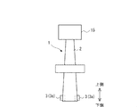
- FIG. 1 is a front view schematically showing a state in which the cutting tool 1 of the present embodiment is connected to a rotational drive mechanism of a cutting apparatus.
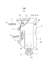
- FIG. 2 is a bottom view schematically showing the cutting tool 1 of the present embodiment.
- the cutting tool 1 includes a holder 2 and a cutting tool 3.
- the holder 2 has a substantially conical shape as a basic form, and for example, an upper end portion is connected to a rotation shaft of the rotation drive mechanism 15 of the cutting apparatus.
- a cutting tool 3 is attached to the lower end of the holder 2 in the circumferential direction.
- the holder 2 is made of, for example, a steel material.
- the shape of the holder 2 may be any shape that can form a hole in the workpiece.
- the horizontal cross section may be a polygonal shape.
- the material of the holder 2 should just be a material which can transmit the driving force of the said rotational drive mechanism 15 to the blade 3 favorably.
- the cutting tool 3 is attached to the lower end portion of the holder 2 so as to protrude from the holder 2 in the radial direction of the holder 2 as shown in FIGS. 1 and 2.
- three cutting tools 3 (3a, 3b, 3c) are arranged at substantially equal intervals in the circumferential direction of the holder 2.
- the blades 3a, 3b, and 3c are arranged at substantially the same mounting angle (for example, a rake angle of 0 °).
- the cutting tools 3 may not be arranged at substantially equal intervals in the circumferential direction of the holder 2.
- the protrusion amount Pa protruding from the holder 2 in the radial direction of the holder 2 in the cutting tool 3a is the radial direction of the holder 2 in the cutting tools 3b and 3c as shown in FIG.
- the protrusion amounts Pb and Pc protruding from the holder 2 are large. That is, the distance Ra from the center of gravity (center) O of the horizontal section of the holder 2 to the tip of the blade 3a is longer than the distances Rb and Rc from the center O of the holder 2 to the tips of the blades 3b and 3c.
- the protrusion amount Pa protruding from the holder 2 in the radial direction of the holder 2 in the cutting tool 3a is larger than the protrusion amounts Pb and Pc protruding from the holder 2 in the radial direction of the holder 2 in the cutting tools 3b and 3c.
- the blades 3a, 3b, and 3c are made of the same material and the attachment angles of the blades 3a, 3b, and 3c are equal (for example, a rake angle of 0 °)
- the cutting resistance of the cutting tool 3a is larger than the cutting resistance of the cutting tools 3b and 3c. growing. Therefore, the rotational axis of the cutting tool 1 that is cutting the workpiece is displaced from the center O of the holder 2.
- the cutting tool 3a is disposed on the surface compared to the cutting tools 3b and 3c so that the rotation axis of the cutting tool 1 that is cutting the workpiece is arranged at a position substantially equal to the center O of the holder 2. It is made of a material with low friction.
- a diamond tip is used as the cutting tool 3a, and a cemented carbide tip is used as the cutting tools 3b and 3c.
- the cutting resistance of the cutting tools 3b and 3c can be made larger than the cutting resistance of the cutting tool 3a.
- the protrusion amount Pa protruding from the holder 2 in the radial direction of the holder 2 in the blade tool 3a is made larger than the protrusion amounts Pb and Pc protruding from the holder 2 in the radial direction of the holder 2 in the blade tools 3b and 3c.
- the cutting force of the cutting tool 3a is balanced with the phenomenon that the cutting resistance of the cutting tools 3b and 3c is larger than the cutting resistance of the cutting tools 3b and 3c.
- the center of the hole formed in the workpiece and the rotation axis of the cutting tool 1 can be arranged at substantially the same position.
- the cutting tool 1 of this embodiment attaches the cutting tools 3a, 3b, and 3c to the holder 2, the hole diameter that forms a protrusion amount Pa protruding from the holder 2 in the radial direction of the holder 2 at least in the cutting tool 3a on the workpiece.
- a hole having a desired diameter can be formed in the workpiece. That is, cutting that can form a hole with a desired diameter in the workpiece without adjusting the protrusion amounts Pb and Pc protruding from the holder 2 in the radial direction of the holder 2 in the cutting tools 3b and 3c with high accuracy.
- the tool 1 can be configured. Therefore, the labor associated with the adjustment of the blade can be reduced.
- FIG. 3 is a perspective view schematically showing the holder 2, the holder 2 being turned upside down and seen from above.
- FIG. 4 is a diagram schematically showing the IV view of FIG. 3.
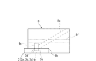
- FIG. 5 is a perspective view schematically showing the cartridge.
- FIG. 6 is a diagram schematically showing the VI view of FIG. 5.
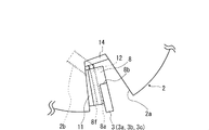
- FIG. 7 is a diagram schematically showing the VII view of FIG. 3.
- the upper part of the holder 2 of the present embodiment is formed in a substantially conical shape, and the lower part is formed in a substantially cylindrical shape.
- the center of gravity of the upper horizontal section and the position of the center of gravity of the lower horizontal section of the holder 2 as viewed from above and below are arranged at substantially equal positions.
- a groove 2a is formed in the lower part of the holder 2 with an interval in the circumferential direction.
- the three groove portions 2 a are arranged at substantially equal intervals in the circumferential direction of the holder 2.
- These groove portions 2 a are provided with openings in the radial direction and the lower side of the holder 2, and the longitudinal direction extends substantially in the vertical direction of the holder 2. These openings are formed so as to spread outward from the center of the holder 2.
- a bolt hole 2b is formed in the vicinity of the bottom of the groove 2a.
- the bolt hole 2 b of the present embodiment is disposed in the vicinity of the corner portion at the bottom of the groove 2 a as viewed from the top and bottom and is inclined with respect to the radial direction of the holder 2.
- the bolt hole 2b should just be arrange
- the cartridge 4 is disposed in the groove 2a of the holder 2 and attached to the holder 2 using a bolt.
- the cartridge 4 includes an attachment mechanism 5 for attaching the blade 3 to the holder 2, a protrusion amount adjusting mechanism 6 for adjusting a protrusion amount of the blade 3 protruding in the radial direction of the holder 2, and a holder in the blade 3. And a height adjusting mechanism 7 for adjusting the position of 2 in the vertical direction.
- a cartridge attached with the blade 3a a cartridge attached with the blade 3b, and a cartridge attached with the blade 3c are prepared.
- the shape of the cutting tool 3 is a thin triangular prism shape, and a through hole 3d is formed so as to penetrate the opposing triangular surface.
- a general shape of the blade can be adopted.
- the attachment mechanism 5 attaches the cutting tool 3 to the holder 2 through the cartridge body 8.
- the cartridge main body 8 of the present embodiment has a substantially quadrangular prism shape as a basic form.
- a bolt hole 8 a for screwing a bolt 9 for attaching the blade 3 is formed at the lower end of the cartridge body 8.
- the blade 3 is attached to the cartridge body 8 by aligning the bolt hole 8a and the through hole 3d of the blade 3 and screwing the bolt 9 into the bolt hole 8a through the through hole 3d of the blade 3. At this time, the corner of the blade 3 protrudes laterally from the cartridge body 8.
- the cartridge body 8 is preferably formed with a notch 8b for fitting a part of the cutting tool 3.
- the blade 3 can be easily aligned by simply fitting the blade 3 into the notch 8b of the cartridge body 8.
- a counterbore 3e is formed around the through hole 3d in the cutting tool 3. Thereby, the bolt head of the bolt 9 can be accommodated in the counterbore part 3 e of the blade 3.
- the cartridge body 8 is formed with a through hole 8c through which a bolt 10 for attaching the cartridge 4 to the holder 2 is passed.
- the through-hole 8 c allows the bolt 10 to pass through the cartridge body 8 with the side surface of the cartridge body 8 in contact with the side surface of the groove 2 a of the holder 2 via the washer 11.
- the holder 2 is arranged so as to be inclined when viewed from above and below.
- the through hole 8c is formed so as to allow the cartridge 4 to move in the vertical direction and allow the cartridge 2 to move in the radial direction.
- the cartridge 4 is attached to the holder 2 by aligning the through hole 8c with the bolt hole 2b of the holder 2 and screwing the bolt 10 into the bolt hole 2b of the holder 2 through the through hole 8c of the cartridge body 8. .
- the rake angle of the cutting tool 3a is, for example, approximately 0 °.
- a notch portion 8 d is formed in the cartridge body 8 so as to be arranged substantially parallel to the seating surface of the bolt 10 so that the seating surface of the bolt 10 makes good surface contact with the cartridge body 8. It is preferable that Thereby, the cartridge 4 can be firmly attached to the holder 2 by the bolt 10.
- a counterbore part 8e in which the bolt head of the bolt 10 is accommodated is formed in the notch part 8d.
- the protrusion amount adjusting mechanism 6 adjusts the protrusion amount of the hexagon socket head bolt 12 screwed into the bolt hole 8 f of the cartridge body 8, so that the protrusion amount protruding from the holder 2 in the radial direction of the holder 2 in the cutting tool 3. Adjust.
- the bolt hole 8 f is formed in the cartridge main body 8 so as to be substantially parallel to the opposing triangular surface of the blade 3 when viewed from above and below, and penetrates the cartridge main body 8.
- a hexagon socket head cap screw 12 is screwed into the bolt hole 8f, and the tip of the hexagon socket head cap screw 12 is protruded from the cartridge main body 8 to be brought into contact with the groove 2a of the holder 2, and in the radial direction of the holder 2 in the cutting tool 3.
- the amount of protrusion protruding from the holder 2 is defined.
- the protrusion amount which protrudes from the said holder 2 in the radial direction of the holder 2 in the blade tool 3 is adjusted by changing the protrusion amount of the front-end
- the height adjusting mechanism 7 adjusts the vertical position of the cutting tool 3 by adjusting the amount of protrusion of the height adjusting piece 13 screwed into the bolt hole 8g of the cartridge body 8.
- the bolt hole 8g is formed on the upper surface of the cartridge body 8 and extends in the vertical direction.
- the height adjustment piece 13 includes a bar screw portion 13a extending in the vertical direction and a contact portion 13b provided at the tip of the bar screw portion 13a.
- the contact portion 13b is brought into contact with the upper surface of the groove portion 2a of the holder 2 so that the vertical position of the cutting tool 3 is set. Stipulate. At this time, the position of the cutting tool 3 in the vertical direction is adjusted by changing the screwing amount of the cartridge body 8 into the bolt hole 8g of the bar screw portion 13a.
- the process of attaching the blade 3a to the holder 2 will be described.
- the bolt hole 8a of the cartridge body 8 and the through hole 3d of the cutting tool 3a are aligned, and the bolt 9 is screwed into the bolt hole 8a through the through hole 3d of the cutting tool 3a.
- the bar screw portion 13a of the height adjusting piece 13 is screwed into the bolt hole 8g of the cartridge body 8 by a predetermined length.
- the cartridge 4 shown in FIG. 5 is configured.
- washers 11 and 14 are arranged between the cartridge 4 and the side surface of the groove portion 2a in the holder 2 and between the cartridge 4 and the bottom surface of the groove portion 2a in the holder 2, respectively. 4 is disposed in the groove 2 a of the holder 2.
- the contact portion 13b of the height adjustment piece 13 in contact with the upper surface of the groove portion 2a in the holder 2, the amount of screwing into the bolt hole 8g of the cartridge body 8 in the bar screw portion 13a of the height adjustment piece 13 To adjust the vertical position of the blade 3a.
- the hexagon socket head bolt 12 is screwed into the bolt hole 8f of the cartridge main body 8, and the tip of the hexagon socket head bolt 12 is protruded from the cartridge main body 8 and brought into contact with the washer 14.
- the screwing amount of the hexagon socket head bolt 12 is adjusted, and the protruding amount protruding from the holder 2 in the radial direction of the holder 2 in the cutting tool 3a is adjusted.
- the process of attaching the cartridge 4 to the holder 2 is completed.
- the cartridge 4 is preferably attached to the holder 2 in the vicinity of the cutting tool 3 so that the tip position of the cutting tool 3 is not displaced.
- the cartridge 4 to which the cutting tool 3b is attached and the cartridge 4 to which the cutting tool 3c is attached are attached to the holder 2.
- the protrusion amounts Pb and Pc protruding from the holder 2 in the radial direction of the holder 2 in the blade 3b and the blade 3c are the protrusion amounts protruding from the holder 2 in the radial direction of the holder 2 in the blade 3a. It adjusts so that it may become small with respect to Pa.
- the cartridge 4 to which the cutting tool 3b is attached and the cartridge 4 to which the cutting tool 3c is attached are provided with the protruding amount adjusting mechanism 6.
- these cartridges 4 are the holders 2 in the cutting tools 3b and 3c.
- the protrusions Pb and Pc protruding from the holder 2 in the radial direction may be attached so as to be smaller than the protrusion amount Pa protruding from the holder 2 in the radial direction of the holder 2 in the cutting tool 3a, and high-precision adjustment is unnecessary. Therefore, the protrusion amount adjusting mechanism 6 may be omitted. Thereby, the structure of the cutting tool 1 can be simplified.
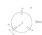
- FIG. 8 is a bottom view schematically showing the cutting tool 20 of the present embodiment.
- the cutting tool 20 of this Embodiment is set as the structure substantially the same as the cutting tool 1 of Embodiment 1, the overlapping description is abbreviate
- the protrusion amount Pa protruding from the holder 2 in the radial direction of the holder 2 in the cutting tool 21a is larger than the protrusion amounts Pb and Pc protruding from the holder 2 in the radial direction of the holder 2 in the cutting tools 21b and 21c. If the blades 21a, 21b, and 21c are substantially equal in material and the attachment angles of the blades 21a, 21b, and 21c are substantially equal, the cutting resistance of the blade 21a is larger than the cutting resistance of the blades 21b and 21c. Therefore, the rotational axis of the cutting tool 20 that is cutting the workpiece is displaced from the center O of the holder 2.
- the rotation axis of the cutting tool 20 that is cutting the workpiece is arranged at a position substantially equal to the center O of the holder 2.
- the inclination angle is greatly inclined in the negative direction of the rotation direction of the holder 2 with respect to the inclination angle of the holder 2 in the circumferential direction of the holder 2. That is, the rake angle ⁇ of the cutting tools 21b and 21c is greatly inclined in the ⁇ direction with respect to the cutting tool 21a.
- the rake angle ⁇ of the cutting tools 21b and 21c may be inclined in the ⁇ direction, and the rake angle ⁇ of the cutting tools 21a may be set to 0 °.
- the rake angle ⁇ of the cutting tools 21b and 21c may be set to 0 °, and the rake angle ⁇ of the cutting tools 21a may be set. May be inclined in the + direction.
- all the rake angles ⁇ of the cutting tools 21a, 21b, and 21c may be inclined in the ⁇ direction, and the rake angles ⁇ of the cutting tools 21b and 21c may be greatly inclined in the ⁇ direction as compared to the rake angle ⁇ of the cutting tools 21a.
- the rake angle ⁇ of the cutting tool 21a may be inclined in the + direction, and the rake angle ⁇ of the cutting tools 21b and 21c may be inclined in the ⁇ direction. At this time, the rake angles ⁇ of the cutting tools 21b and 21c are not necessarily equal.
- the cutting resistance of the cutting tools 21b and 21c can be made larger than the cutting resistance of the cutting tool 21a.
- the protrusion amount Pa protruding from the holder 2 in the radial direction of the holder 2 in the blade 21a is made larger than the protrusion amounts Pb and Pc protruding from the holder 2 in the radial direction of the holder 2 in the blades 21b and 21c.
- the center of the hole formed in the workpiece and the rotation axis of the cutting tool 20 can be arranged at substantially the same position.
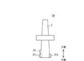
- FIG. 9 is a front view schematically showing the cutting tool 30 of the present embodiment.
- FIG. 10 is a bottom view schematically showing the cutting tool 30 of the present embodiment.
- the cutting tool 30 of this Embodiment is also set as the structure substantially the same as the cutting tool 1 of Embodiment 1, the overlapping description is abbreviate
- the protrusion amount Pa protruding from the holder 2 in the radial direction of the holder 2 in the blade 31a is compared with the protrusion amounts Pb and Pc protruding from the holder 2 in the radial direction of the holder 2 in the blades 31b and 31c. If the blades 31a, 31b, and 31c are substantially equal in material and the attachment angles of the blades 31a, 31b, and 31c are substantially equal, the cutting resistance of the blade 31a becomes larger than the cutting resistance of the blades 31b and 31c. Therefore, the rotational axis of the cutting tool 30 that is cutting the workpiece is displaced from the center O of the holder 2.
- the guide pad 32 is provided in the vicinity of the cutting tools 31b and 31c so that the rotation axis of the cutting tool 30 that is cutting the workpiece is arranged at a position substantially equal to the center O of the holder 2. Has been placed.
- the guide pad 32 has a cutting tool in the circumferential direction of the holder 2 as viewed from the vertical direction, for example, so that the cutting tools 31b and 31c are not pushed into the cutting object and the cutting tools 31b and 31c are not bent. It arrange
- the surfaces of the guide pads 32 facing the holder 2 correspond to the outer peripheral shape of the holder 2, that is, are formed so as to be in surface contact with the holder 2.
- the surface of the guide pad 32 opposite to the surface facing the holder 2 is formed as a curved surface.
- the thickness of the guide pad 32 is such that the distance from the center of the holder 2 to the surface opposite to the surface of the guide pad 32 facing the holder 2 is adjusted so that the amount of protrusion is the smallest from the center of the holder 2. Is set to be shorter than any of the distance Ram from the center of the holder 2, the distance Rb from the center of the holder 2 to the tip of the blade 31b, and the distance Rc from the center of the holder 2 to the tip of the blade 31c. ing. That is, the guide pad 32 does not protrude from the holder 2 in the radial direction of the holder 2 with respect to the distal ends of the cutting tools 31a, 31b, 31c.
- These guide pads 32 are made of artificial diamond or brass, for example, and are attached to the holder 2 by fixing means such as bolts.
- the force pushed into the cutting tools 31b and 31c by the cutting of the cutting tool 31a is received by the guide pad 32, and the rotational axis of the cutting tool 30 that is cutting the workpiece is arranged at a position substantially equal to the center O of the holder 2.
- the center of the hole formed in the workpiece and the rotation axis of the cutting tool 30 can be arranged at substantially the same position.
- the cutting tool may be configured by combining any of Embodiments 1 to 3.
- the cutting tool of the above-described embodiment includes three cutting tools, but the number of cutting tools may be plural.
- the present invention can be used as a cutting tool including a plurality of cutting tools.
Landscapes
- Engineering & Computer Science (AREA)
- Mechanical Engineering (AREA)
- Milling Processes (AREA)
- Processing Of Stones Or Stones Resemblance Materials (AREA)
- Cutting Tools, Boring Holders, And Turrets (AREA)
Abstract
刃具の調整に伴う労力を軽減することができる切削工具を提供する。本発明の一形態に係る切削工具(1)は、ホルダ(2)に第1の刃具(3a)と第2の刃具(3b)とが取り付けられており、駆動機構(15)に連結される側を上側とする上下方向と直交する方向を水平方向とした場合、第1の刃具(3a)におけるホルダ(2)から略水平方向に突出する突出量(Pa)は、第2の刃具(3b)におけるホルダ(2)から略水平方向に突出する突出量(Pb)に比べて大きく、回転軸が、ホルダ(2)が回転しつつ被切削物を切削している際におけるホルダ(2)の水平断面の重心位置と略等しい位置に配置されるように、第1の刃具(3a)における被切削物に対する切削抵抗が第2の刃具(3b)における被切削物に対する切削抵抗に比べて小さい。
Description
本発明は、切削工具に関し、複数の刃具を備える切削工具に関する。
切削工具は、例えば被切削物に孔を形成するために用いられ、特許文献1に開示されているように複数の刃具がホルダに取り付けられている。このとき、複数の刃具におけるホルダから略水平方向に突出する突出量が略等しくなるように、複数の刃具がホルダに取り付けられる。
このような切削工具は、複数の刃具におけるホルダから略水平方向に突出する突出量が略等しくなるように当該複数の刃具がホルダに取り付けられるので、刃具を取り換えた後に複数の刃具全ての当該突出量を再度、調整し直す必要がある。そのため、刃具の調整が煩雑である。
本発明は、このような問題点を解決するためになされたものであり、刃具の調整に伴う労力を軽減することができる切削工具を提供する。
本発明の一形態に係る切削工具は、ホルダに第1の刃具と第2の刃具とが取り付けられており、駆動機構に連結される側を上側とする上下方向と直交する方向を水平方向とした場合、前記第1の刃具における前記ホルダから略水平方向に突出する突出量は、前記第2の刃具における前記ホルダから略水平方向に突出する突出量に比べて大きく、回転軸が、前記ホルダが回転しつつ被切削物を切削している際における前記ホルダの水平断面の重心位置と略等しい位置に配置されるように、前記第1の刃具における前記被切削物に対する切削抵抗が前記第2の刃具における前記被切削物に対する切削抵抗に比べて小さい。
上述の切削工具において、前記第1の刃具の材質は、前記第2の刃具の材質に比べて表面の摩擦が小さいことが好ましい。
上述の切削工具において、前記第2の刃具における前記ホルダの周方向への傾斜角度は、前記第1の刃具における前記ホルダの周方向への傾斜角度に比べて前記ホルダの回転方向の負の方向に大きく傾斜していることが好ましい。
本発明の一形態に係る切削工具は、ホルダに第1の刃具と第2の刃具とが取り付けられており、駆動機構に連結される側を上側とする上下方向と直交する方向を水平方向とした場合、前記第1の刃具における前記ホルダから略水平方向に突出する突出量は、前記第2の刃具における前記ホルダから略水平方向に突出する突出量に比べて大きく、回転軸が、前記ホルダが回転しつつ被切削物を切削している際における前記ホルダの水平断面の重心位置と略等しい位置に配置されるように、前記ホルダにおける前記第2の刃具の近傍にガイドパッドが取り付けられている。
上述の切削工具において、前記第1の刃具における前記ホルダからの突出量を調整する調整機構を備え、前記第2の刃具における前記ホルダからの突出量を調整する調整機構が省略されていてもよい。
以上、説明したように、刃具の調整に伴う労力を軽減することができる切削工具を提供することができる。
以下、本発明を実施するための最良の形態について、添付図面を参照しながら説明する。但し、本発明が以下の実施の形態に限定される訳ではない。また、説明を明確にするため、以下の記載及び図面は、適宜、簡略化されている。但し、以下の説明では、切削装置の回転駆動機構に連結される側を上側として説明するが、切削工具の使用形態によって方向は適宜変更される。
<実施の形態1>
本実施の形態の切削工具を説明する。先ず、本実施の形態の切削工具の基本形態を説明する。本実施の形態の切削工具は、例えば被切削物に孔を形成する際に用いることができる。
本実施の形態の切削工具を説明する。先ず、本実施の形態の切削工具の基本形態を説明する。本実施の形態の切削工具は、例えば被切削物に孔を形成する際に用いることができる。
図1は、本実施の形態の切削工具1が切削装置の回転駆動機構に連結された状態を概略的に示す正面図である。図2は、本実施の形態の切削工具1を概略的に示す底面図である。図1及び図2に示すように、切削工具1は、ホルダ2と刃具3とを備えている。
ホルダ2は、図1及び図2に示すように、略円錐形状を基本形態とし、例えば上端部が切削装置の回転駆動機構15の回転軸に連結される。ホルダ2の下端部には、周方向に刃具3が取り付けられている。
このホルダ2は、例えば鋼材等で構成されている。但し、ホルダ2の形状は、被切削物に孔を形成することができる形状であればよく、例えば水平断面が多角形状でもよい。また、ホルダ2の材質は、当該回転駆動機構15の駆動力を良好に刃具3に伝達することができる材質であればよい。
刃具3は、図1及び図2に示すように、ホルダ2の径方向に当該ホルダ2から突出するように、ホルダ2の下端部に取り付けられている。本実施の形態では、3個の刃具3(3a、3b、3c)がホルダ2における周方向に略等間隔で配置されている。そして、刃具3a、3b、3cは、略等しい取付角度(例えば、すくい角0°)で配置されている。但し、刃具3はホルダ2における周方向に略等間隔で配置されていなくてもよい。
刃具3aにおけるホルダ2の径方向に当該ホルダ2から突出する(即ち、ホルダ2から略水平方向に突出する)突出量Paは、図2に示すように、刃具3b、3cにおけるホルダ2の径方向に当該ホルダ2から突出する突出量Pb、Pcに比べて大きい。つまり、ホルダ2における水平断面の重心位置(中心)Oから刃具3aの先端部までの距離Raは、ホルダ2の中心Oから刃具3b、3cの先端部までの距離Rb、Rcに比べて長い。
ここで、刃具3aにおけるホルダ2の径方向に当該ホルダ2から突出する突出量Paが、刃具3b、3cにおけるホルダ2の径方向に当該ホルダ2から突出する突出量Pb、Pcに比べて大きく、例えば刃具3a、3b、3cの材質が等しく、しかも刃具3a、3b、3cの取付角度が等しい(例えば、すくい角0°)場合、刃具3aの切削抵抗が刃具3b、3cの切削抵抗に比べて大きくなる。そのため、被切削物を切削中の切削工具1の回転軸が、ホルダ2の中心Oからずれてしまう。
そこで、本実施の形態では、被切削物を切削中の切削工具1の回転軸がホルダ2の中心Oと略等しい位置に配置されるように、刃具3aが刃具3b、3cに比べて表面の摩擦が小さい材質で構成されている。例えば、刃具3aとしてダイヤチップを用い、刃具3b、3cとして超硬チップを用いる。
これにより、刃具3b、3cの切削抵抗を刃具3aの切削抵抗に比べて大きくすることができる。その結果、刃具3aにおけるホルダ2の径方向に当該ホルダ2から突出する突出量Paを、刃具3b、3cにおけるホルダ2の径方向に当該ホルダ2から突出する突出量Pb、Pcに比べて大きくすることによって、刃具3aの切削抵抗が刃具3b、3cの切削抵抗に比べて大きくなる現象と均衡がとれ、被切削物を切削中の切削工具1の回転軸をホルダ2の中心Oと略等しい位置に配置することができ、言い換えると、被切削物に形成される孔の中心と切削工具1の回転軸とを略等しい位置に配置することができる。
本実施の形態の切削工具1は、刃具3a、3b、3cをホルダ2に取り付けるとき、少なくとも刃具3aにおけるホルダ2の径方向に当該ホルダ2から突出する突出量Paを被切削物に形成する孔径に合わせて当該刃具3aをホルダ2に取り付けると、被切削物に所望の径の孔を形成することができる。つまり、刃具3b、3cにおけるホルダ2の径方向に当該ホルダ2から突出する突出量Pb、Pcを高精度に調整しなくても、被切削物に所望の径の孔を形成することができる切削工具1を構成することができる。したがって、刃具の調整に伴う労力を軽減することができる。
次に、本実施の形態の切削工具1の具体的な構成を説明する。図3は、ホルダ2を概略的に示し、当該ホルダ2を上下反転させ、上方から見た斜視図である。図4は、図3のIV視を概略的に示す図である。図5は、カートリッジを概略的に示す斜視図である。図6は、図5のVI視を概略的に示す図である。図7は、図3のVII視を概略的に示す図である。
図3に示すように、本実施の形態のホルダ2の上部は略円錐形状に形成され、下部が略円柱形状に形成されている。そして、上下方向から見てホルダ2における上部の水平断面の重心位置と下部の水平断面の重心位置とは、略等しい位置に配置されている。
ホルダ2の下部には、周方向に間隔を開けて溝部2aが形成されている。本実施の形態では、3個の溝部2aがホルダ2の周方向に略等間隔で配置されている。これらの溝部2aは、ホルダ2の径方向及び下側に開口部を備えており、長手方向がホルダ2の略上下方向に向かって延在している。そして、これらの開口部は、ホルダ2の中心から外方に向かって広がるように形成されている。
溝部2aの底部近傍には、図4に示すように、ボルト穴2bが形成されている。本実施の形態のボルト穴2bは、図7に示すように、上下方向から見て溝部2aの底部における角部近傍にホルダ2の径方向に対して傾斜して配置されている。但し、ボルト穴2bは、後述するカートリッジ4を良好に固定することができる位置に配置されていればよい。
カートリッジ4は、ホルダ2の溝部2a内に配置され、ボルトを用いてホルダ2に取り付けられる。先ずカートリッジ4の構成を説明する。カートリッジ4は、図5に示すように、刃具3をホルダ2に取り付ける取付機構5と、刃具3におけるホルダ2の径方向に突出する突出量を調整する突出量調整機構6と、刃具3におけるホルダ2の上下方向への位置を調整する高さ調整機構7と、を備えている。
ここで、本実施の形態のカートリッジ4としては、刃具3aを取り付けたカートリッジと、刃具3bを取り付けたカートリッジと、刃具3cを取り付けたカートリッジと、を用意する。刃具3の形状は、薄い三角柱形状とされており、向かい合う三角形状の面を貫通するように貫通孔3dが形成されている。但し、刃具3の形状としては、一般的な刃具の形状を採用することができる。
取付機構5は、カートリッジ本体8を介して刃具3をホルダ2に取り付ける。本実施の形態のカートリッジ本体8は、図5に示すように、略四角柱形状を基本形態としている。そして、カートリッジ本体8の下端部には、図6に示すように、刃具3を取り付けるためのボルト9を捻じ込むためのボルト穴8aが形成されている。
このボルト穴8aと刃具3の貫通孔3dとを位置合わせし、ボルト9を刃具3の貫通孔3dを介してボルト穴8aに捻じ込むことによって、刃具3がカートリッジ本体8に取り付けられる。このとき、刃具3の角部がカートリッジ本体8から側方に突出する。
ここで、カートリッジ本体8には、刃具3の一部を嵌め込むための切り欠き部8bが形成されていることが好ましい。これにより、刃具3をカートリッジ本体8の切り欠き部8bに嵌め込むだけで、刃具3の位置合わせを簡単に行うことができる。
また、刃具3における貫通孔3dの周辺にザグリ部3eが形成されていることが好ましい。これにより、ボルト9のボルト頭を刃具3のザグリ部3eに収容することができる。
カートリッジ本体8には、図5に示すように、カートリッジ4をホルダ2に取り付けるためのボルト10を通すための貫通孔8cが形成されている。貫通孔8cは、図5乃至図7に示すように、カートリッジ本体8の側面をホルダ2の溝部2aの側面に座金11を介して接触させた状態で、カートリッジ本体8を介して当該ボルト10をホルダ2のボルト穴2bに捻じ込むことができるように、上下方向から見て傾斜して配置されている。そして、貫通孔8cは、カートリッジ4の上下方向の移動を許容し、且つカートリッジ4におけるホルダ2の径方向への移動を許容するように形成されている。
この貫通孔8cとホルダ2のボルト穴2bとを位置合わせし、ボルト10をカートリッジ本体8の貫通孔8cを介してホルダ2のボルト穴2bに捻じ込むことによって、カートリッジ4がホルダ2に取り付けられる。このとき、刃具3aのすくい角は例えば略0°になる。
ここで、図5に示すように、ボルト10の座面がカートリッジ本体8に良好に面接触するように、ボルト10の座面と略平行に配置される切り欠き部8dがカートリッジ本体8に形成されていることが好ましい。これにより、ボルト10によってカートリッジ4を強固にホルダ2に取り付けることができる。
また、当該切り欠き部8dには、ボルト10のボルト頭が収容されるザグリ部8eが形成されていることが好ましい。
突出量調整機構6は、カートリッジ本体8のボルト孔8fに捻じ込まれた六角穴付きボルト12の突出量を調整することで、刃具3におけるホルダ2の径方向に当該ホルダ2から突出する突出量を調整する。
ボルト孔8fは、図6に示すように、上下方向から見ると刃具3における向かい合う三角形状の面と略平行に、カートリッジ本体8に形成されており、カートリッジ本体8を貫通する。
このボルト孔8fに六角穴付きボルト12を捻じ込み、当該六角穴付きボルト12の先端部をカートリッジ本体8から突出させてホルダ2の溝部2aに接触させ、刃具3におけるホルダ2の径方向に当該ホルダ2から突出する突出量を規定する。このとき、六角穴付きボルト12の先端部の突出量を変化させることで、刃具3におけるホルダ2の径方向に当該ホルダ2から突出する突出量を調整する。
高さ調整機構7は、カートリッジ本体8のボルト穴8gに捻じ込まれた高さ調整コマ13の突出量を調整することで、刃具3における上下方向の位置を調整する。ボルト穴8gは、カートリッジ本体8の上面に形成されており、上下方向に延在している。高さ調整コマ13は、上下方向に延在する棒ネジ部13aと、棒ネジ部13aの先端部に設けられた接触部13bと、を備えている。
棒ネジ部13aをカートリッジ本体8のボルト穴8gに捻じ込み、カートリッジ4をホルダ2に取り付ける際に、ホルダ2の溝部2aの上面に接触部13bを接触させて、刃具3における上下方向の位置を規定する。このとき、棒ネジ部13aにおけるカートリッジ本体8のボルト穴8gへの捻じ込み量を変化させることで、刃具3における上下方向の位置を調整する。
次に、刃具3aのホルダ2への取付工程を説明する。先ず、カートリッジ本体8のボルト穴8aと刃具3aの貫通孔3dとを位置合わせし、ボルト9を刃具3aの貫通孔3dを介してボルト穴8aに捻じ込む。そして、カートリッジ本体8のボルト穴8gに高さ調整コマ13の棒ネジ部13aを所定の長さ捻じ込む。これにより、図5に示すカートリッジ4が構成される。
次に、図7に示すように、カートリッジ4とホルダ2における溝部2aの側面との間、及びカートリッジ4とホルダ2における溝部2aの底面との間に夫々、座金11、14を配置し、カートリッジ4をホルダ2の溝部2a内に配置する。このとき、高さ調整コマ13の接触部13bをホルダ2における溝部2aの上面に接触させた状態で、高さ調整コマ13の棒ネジ部13aにおけるカートリッジ本体8のボルト穴8gへの捻じ込み量を調整し、刃具3aにおける上下方向の位置を調整する。
次に、カートリッジ本体8のボルト孔8fに六角穴付きボルト12を捻じ込み、六角穴付きボルト12の先端部をカートリッジ本体8から突出させて座金14に接触させる。このとき、六角穴付きボルト12の捻じ込み量を調整し、刃具3aにおけるホルダ2の径方向に当該ホルダ2から突出する突出量を調整する。
次に、カートリッジ本体8の貫通孔8cにボルト10を通し、当該ボルト10をホルダ2のボルト穴2bに捻じ込むと、カートリッジ4のホルダ2への取付工程が終了する。なお、刃具3の先端位置がずれないように、カートリッジ4を刃具3の近傍でホルダ2に取り付けることが好ましい。
上述の要領で、刃具3bが取り付けられたカートリッジ4及び刃具3cが取り付けられたカートリッジ4をホルダ2に取り付ける。このとき、上述したように、刃具3b及び刃具3cにおけるホルダ2の径方向に当該ホルダ2から突出する突出量Pb、Pcが、刃具3aにおけるホルダ2の径方向に当該ホルダ2から突出する突出量Paに対して小さくなるように調整される。
なお、本実施の形態では、刃具3bが取り付けられたカートリッジ4及び刃具3cが取り付けられたカートリッジ4が突出量調整機構6を備えているが、これらのカートリッジ4は刃具3b、3cにおけるホルダ2の径方向に当該ホルダ2から突出する突出量Pb、Pcを刃具3aにおけるホルダ2の径方向に当該ホルダ2から突出する突出量Paに対して小さくなるように取り付ければよく、精度の高い調整は不要なので、突出量調整機構6を省略してもよい。これにより、切削工具1の構成を簡略化することができる。
<実施の形態2>
本実施の形態の切削工具20は、刃具21a、21b、21cを等しい材質で構成している。図8は、本実施の形態の切削工具20を概略的に示す底面図である。なお、本実施の形態の切削工具20は、実施の形態1の切削工具1と略同様の構成とされているため、重複する説明は省略し、等しい要素には同一の符号を付している。
本実施の形態の切削工具20は、刃具21a、21b、21cを等しい材質で構成している。図8は、本実施の形態の切削工具20を概略的に示す底面図である。なお、本実施の形態の切削工具20は、実施の形態1の切削工具1と略同様の構成とされているため、重複する説明は省略し、等しい要素には同一の符号を付している。
上述のように、刃具21aにおけるホルダ2の径方向に当該ホルダ2から突出する突出量Paが、刃具21b、21cにおけるホルダ2の径方向に当該ホルダ2から突出する突出量Pb、Pcに対して大きく、刃具21a、21b、21cの材質が略等しく、しかも刃具21a、21b、21cの取付角度が略等しいと、刃具21aの切削抵抗が刃具21b、21cの切削抵抗に比べて大きくなる。そのため、被切削物を切削中の切削工具20の回転軸が、ホルダ2の中心Oからずれてしまう。
そこで、本実施の形態では、被切削物を切削中の切削工具20の回転軸が、ホルダ2の中心Oと略等しい位置に配置されるように、刃具21b、21cにおけるホルダ2の周方向への傾斜角度が、刃具21aにおけるホルダ2の周方向への傾斜角度に対して、ホルダ2の回転方向の負の方向に大きく傾斜している。つまり、刃具21b、21cは、刃具21aに対してすくい角θが-方向に大きく傾斜している。
例えば、刃具21b、21cのすくい角θを-方向に傾斜させ、刃具21aのすくい角θを0°にしてもよく、刃具21b、21cのすくい角θを0°にし、刃具21aのすくい角θを+方向に傾斜させてもよい。また、刃具21a、21b、21cのすくい角θを全て-方向に傾斜させ、刃具21b、21cのすくい角θを刃具21aのすくい角θに比べて-方向に大きく傾斜させてもよい。さらに、刃具21aのすくい角θを+方向に傾斜させ、刃具21b、21cのすくい角θを-方向に傾斜させてもよい。このとき、刃具21b、21cのすくい角θは必ずしも等しくなくてよい。
これにより、刃具21b、21cの切削抵抗を刃具21aの切削抵抗に比べて大きくすることができる。その結果、刃具21aにおけるホルダ2の径方向に当該ホルダ2から突出する突出量Paを、刃具21b、21cにおけるホルダ2の径方向に当該ホルダ2から突出する突出量Pb、Pcに比べて大きくすることによって、刃具21aの切削抵抗が刃具21b、21cの切削抵抗に比べて大きくなる現象と均衡がとれ、被切削物を切削中の切削工具20の回転軸をホルダ2の中心Oと略等しい位置に配置することができ、言い換えると、被切削物に形成される孔の中心と切削工具20の回転軸とを略等しい位置に配置することができる。
<実施の形態3>
本実施の形態の切削工具30は、刃具31a、31b、31cを等しい材質で構成している。図9は、本実施の形態の切削工具30を概略的に示す正面図である。図10は、本実施の形態の切削工具30を概略的に示す底面図である。なお、本実施の形態の切削工具30も、実施の形態1の切削工具1と略同様の構成とされているため、重複する説明は省略し、等しい要素には同一の符号を付している。
本実施の形態の切削工具30は、刃具31a、31b、31cを等しい材質で構成している。図9は、本実施の形態の切削工具30を概略的に示す正面図である。図10は、本実施の形態の切削工具30を概略的に示す底面図である。なお、本実施の形態の切削工具30も、実施の形態1の切削工具1と略同様の構成とされているため、重複する説明は省略し、等しい要素には同一の符号を付している。
上述のように、刃具31aにおけるホルダ2の径方向に当該ホルダ2から突出する突出量Paが、刃具31b、31cにおけるホルダ2の径方向に当該ホルダ2から突出する突出量Pb、Pcに対して大きく、刃具31a、31b、31cの材質が略等しく、しかも刃具31a、31b、31cの取付角度が略等しいと、刃具31aの切削抵抗が刃具31b、31cの切削抵抗に比べて大きくなる。そのため、被切削物を切削中の切削工具30の回転軸が、ホルダ2の中心Oからずれてしまう。
そこで、本実施の形態では、被切削物を切削中の切削工具30の回転軸が、ホルダ2の中心Oと略等しい位置に配置されるように、刃具31b、31cの近傍にガイドパッド32が配置されている。
ガイドパッド32は、被切削物を切削中に刃具31b、31cが当該被切削物に押し込まれて、刃具31b、31cが撓まないように、例えば上下方向から見てホルダ2の周方向で刃具31b、31cを挟み込むように配置されている。そして、ガイドパッド32は、被切削物に孔を形成し終えて切削工具30を引き上げる際に、刃具31a、31b、31cより先にガイドパッド32が被切削物に接触し終えるように、刃具31b、31cの上部に配置されている。
これらのガイドパッド32におけるホルダ2と向かい合う面は、ホルダ2の外周形状に対応する、即ちホルダ2と面接触するように形成されている。そして、ガイドパッド32におけるホルダ2と向かい合う面に対して逆側の面は、湾曲面に形成されている。
ガイドパッド32の厚さは、ホルダ2の中心からガイドパッド32におけるホルダ2と向かい合う面に対して逆側の面までの距離が、ホルダ2の中心から最も突出量を少なく調整した刃具31aの先端部までの距離Ramin、ホルダ2の中心から刃具31bの先端部までの距離Rb、及びホルダ2の中心から刃具31cの先端部までの距離Rcの何れの距離よりも短くなうように、設定されている。つまり、ガイドパッド32が刃具31a、31b、31cの先端部に対してホルダ2の径方向に当該ホルダ2から突出しない。
これらのガイドパッド32は、例えば人工ダイヤや真鍮によって構成され、ボルト等の固定手段によってホルダ2に取り付けられている。
これにより、刃具31aの切削によって刃具31b、31c側に押し込まれる力をガイドパッド32で受け止めて、被切削物を切削中の切削工具30の回転軸をホルダ2の中心Oと略等しい位置に配置することができ、言い換えると、被切削物に形成される孔の中心と切削工具30の回転軸とを略等しい位置に配置することができる。
以上、本発明の実施の形態を説明したが、上記に限らず、本発明の技術的思想を逸脱しない範囲で、変更することが可能である。例えば、実施の形態1~3の何れかを組み合わせて切削工具を構成してもよい。
上述の実施の形態の切削工具は、3個の刃具を備えているが、刃具の個数は複数であればよい。
上述の実施の形態では、刃具3aのみを他の刃具3b、3cに対してホルダ2の径方向に当該ホルダ2から突出させているが、他の刃具に対してホルダ2の径方向に当該ホルダ2から突出させる刃具を少なくとも1個備えていればよい。
この出願は、2013年7月24日に出願された日本出願特願2013-153289を基礎とする優先権を主張し、その開示の全てをここに取り込む。
本発明は、複数の刃具を備える切削工具として利用可能である。
1 切削工具
2 ホルダ、2a 溝部、2b ボルト穴
3(3a、3b、3c) 刃具、3d 貫通孔、3e ザグリ部
4 カートリッジ
5 取付機構
6 突出量調整機構
7 調整機構
8 カートリッジ本体、8a ボルト穴、8b 切り欠き部、8c 貫通孔、8d 切り欠き部、8e ザグリ部、8f ボルト孔、8g ボルト穴
9、10 ボルト
11、14 座金
12 六角穴付きボルト
13 調整コマ、13a 棒ネジ部、13b 接触部
15 回転駆動機構
20 切削工具
21a、21b、21c 刃具
30 切削工具
31a、31b、31c 刃具
32 ガイドパッド
O ホルダの中心
Pa、Pb、Pc 刃具の突出量
Ra、Rb、Rc ホルダの中心から刃具の先端部までの距離
θ すくい角
2 ホルダ、2a 溝部、2b ボルト穴
3(3a、3b、3c) 刃具、3d 貫通孔、3e ザグリ部
4 カートリッジ
5 取付機構
6 突出量調整機構
7 調整機構
8 カートリッジ本体、8a ボルト穴、8b 切り欠き部、8c 貫通孔、8d 切り欠き部、8e ザグリ部、8f ボルト孔、8g ボルト穴
9、10 ボルト
11、14 座金
12 六角穴付きボルト
13 調整コマ、13a 棒ネジ部、13b 接触部
15 回転駆動機構
20 切削工具
21a、21b、21c 刃具
30 切削工具
31a、31b、31c 刃具
32 ガイドパッド
O ホルダの中心
Pa、Pb、Pc 刃具の突出量
Ra、Rb、Rc ホルダの中心から刃具の先端部までの距離
θ すくい角
Claims (5)
- ホルダに第1の刃具と第2の刃具とが取り付けられており、
駆動機構に連結される側を上側とする上下方向と直交する方向を水平方向とした場合、前記第1の刃具における前記ホルダから略水平方向に突出する突出量は、前記第2の刃具における前記ホルダから略水平方向に突出する突出量に比べて大きく、
回転軸が、前記ホルダが回転しつつ被切削物を切削している際における前記ホルダの水平断面の重心位置と略等しい位置に配置されるように、前記第1の刃具における前記被切削物に対する切削抵抗が前記第2の刃具における前記被切削物に対する切削抵抗に比べて小さい切削工具。 - 前記第1の刃具の材質は、前記第2の刃具の材質に比べて表面の摩擦が小さい請求項1に記載の切削工具。
- 前記第2の刃具における前記ホルダの周方向への傾斜角度は、前記第1の刃具における前記ホルダの周方向への傾斜角度に比べて前記ホルダの回転方向の負の方向に大きく傾斜している請求項1又は2に記載の切削工具。
- ホルダに第1の刃具と第2の刃具とが取り付けられており、
駆動機構に連結される側を上側とする上下方向と直交する方向を水平方向とした場合、前記第1の刃具における前記ホルダから略水平方向に突出する突出量は、前記第2の刃具における前記ホルダから略水平方向に突出する突出量に比べて大きく、
回転軸が、前記ホルダが回転しつつ被切削物を切削している際における前記ホルダの水平断面の重心位置と略等しい位置に配置されるように、前記ホルダにおける前記第2の刃具の近傍にガイドパッドが取り付けられている切削工具。 - 前記第1の刃具における前記ホルダからの突出量を調整する調整機構を備え、
前記第2の刃具における前記ホルダからの突出量を調整する調整機構が省略されている請求項1乃至4のいずれか1項に記載の切削工具。
Priority Applications (2)
| Application Number | Priority Date | Filing Date | Title |
|---|---|---|---|
| CN201480027149.7A CN105377487A (zh) | 2013-07-24 | 2014-06-03 | 切削工具 |
| US14/892,932 US20160193671A1 (en) | 2013-07-24 | 2014-06-03 | Cutting tool |
Applications Claiming Priority (2)
| Application Number | Priority Date | Filing Date | Title |
|---|---|---|---|
| JP2013-153289 | 2013-07-24 | ||
| JP2013153289A JP5999042B2 (ja) | 2013-07-24 | 2013-07-24 | 切削工具 |
Publications (1)
| Publication Number | Publication Date |
|---|---|
| WO2015011868A1 true WO2015011868A1 (ja) | 2015-01-29 |
Family
ID=52392936
Family Applications (1)
| Application Number | Title | Priority Date | Filing Date |
|---|---|---|---|
| PCT/JP2014/002959 Ceased WO2015011868A1 (ja) | 2013-07-24 | 2014-06-03 | 切削工具 |
Country Status (4)
| Country | Link |
|---|---|
| US (1) | US20160193671A1 (ja) |
| JP (1) | JP5999042B2 (ja) |
| CN (1) | CN105377487A (ja) |
| WO (1) | WO2015011868A1 (ja) |
Cited By (1)
| Publication number | Priority date | Publication date | Assignee | Title |
|---|---|---|---|---|
| JP2020203353A (ja) * | 2019-06-18 | 2020-12-24 | 真辺工業株式会社 | 回転切削工具 |
Citations (2)
| Publication number | Priority date | Publication date | Assignee | Title |
|---|---|---|---|---|
| JP2004322259A (ja) * | 2003-04-24 | 2004-11-18 | Aisin Seiki Co Ltd | 穴加工工具、穴加工方法 |
| JP2007038310A (ja) * | 2005-07-29 | 2007-02-15 | Shin Caterpillar Mitsubishi Ltd | 切削工具 |
Family Cites Families (13)
| Publication number | Priority date | Publication date | Assignee | Title |
|---|---|---|---|---|
| JP2759866B2 (ja) * | 1993-11-26 | 1998-05-28 | 三菱自動車工業株式会社 | 中ぐり用回転切削工具 |
| DE19621295C2 (de) * | 1996-05-25 | 1998-08-27 | Mapal Fab Praezision | Reibahle für die spanabhebende Feinbearbeitung |
| DE19717835A1 (de) * | 1997-04-26 | 1998-10-29 | Heller Geb Gmbh Maschf | Werkzeug sowie Verfahren zur Bearbeitung von Bohrungen mit einem derartigen Werkzeug |
| DE19719892A1 (de) * | 1997-05-12 | 1998-11-19 | Maier Kg Andreas | Feinstbearbeitungswerkzeug |
| DE19720823A1 (de) * | 1997-05-16 | 1998-11-19 | Heller Geb Gmbh Maschf | Werkzeug mit einem Grundkörper sowie Verfahren zur Bearbeitung von Bohrungen in einem Werkstück unter Verwendung eines solchen Werkzeuges |
| US6299391B1 (en) * | 1997-11-12 | 2001-10-09 | Caterpillar Inc. | Boring tool assembly |
| US5921727A (en) * | 1998-01-20 | 1999-07-13 | Cogsdill Tool Products, Inc. | Reamer with friction resistant layer and method for forming same |
| DE10144759A1 (de) * | 2001-09-11 | 2003-03-27 | Komet Stahlhalter Werkzeuge | Kombinationswerkzeug |
| DE10159431B4 (de) * | 2001-12-04 | 2005-10-20 | Mapal Fab Praezision | Werkzeug zur Feinstbearbeitung von Oberflächen |
| JP2004181607A (ja) * | 2002-12-06 | 2004-07-02 | Toyota Motor Corp | エンジンブロックのボア内面の加工方法 |
| JP5896867B2 (ja) * | 2012-09-11 | 2016-03-30 | 富士精工株式会社 | 下穴の仕上げ加工方法 |
| CN203045016U (zh) * | 2012-12-03 | 2013-07-10 | 綦江齿轮传动有限公司 | 组合式内刃成型铣刀 |
| CN202984775U (zh) * | 2013-01-15 | 2013-06-12 | 宁波川景誉机械科技发展有限公司 | 一种具有调节刀片高度功能的铣刀装置 |
-
2013
- 2013-07-24 JP JP2013153289A patent/JP5999042B2/ja not_active Expired - Fee Related
-
2014
- 2014-06-03 WO PCT/JP2014/002959 patent/WO2015011868A1/ja not_active Ceased
- 2014-06-03 US US14/892,932 patent/US20160193671A1/en not_active Abandoned
- 2014-06-03 CN CN201480027149.7A patent/CN105377487A/zh active Pending
Patent Citations (2)
| Publication number | Priority date | Publication date | Assignee | Title |
|---|---|---|---|---|
| JP2004322259A (ja) * | 2003-04-24 | 2004-11-18 | Aisin Seiki Co Ltd | 穴加工工具、穴加工方法 |
| JP2007038310A (ja) * | 2005-07-29 | 2007-02-15 | Shin Caterpillar Mitsubishi Ltd | 切削工具 |
Cited By (2)
| Publication number | Priority date | Publication date | Assignee | Title |
|---|---|---|---|---|
| JP2020203353A (ja) * | 2019-06-18 | 2020-12-24 | 真辺工業株式会社 | 回転切削工具 |
| JP7074348B2 (ja) | 2019-06-18 | 2022-05-24 | 真辺工業株式会社 | リーマ |
Also Published As
| Publication number | Publication date |
|---|---|
| CN105377487A (zh) | 2016-03-02 |
| US20160193671A1 (en) | 2016-07-07 |
| JP5999042B2 (ja) | 2016-09-28 |
| JP2015024447A (ja) | 2015-02-05 |
Similar Documents
| Publication | Publication Date | Title |
|---|---|---|
| US10010332B2 (en) | Cutting tool and corresponding assembly | |
| KR20110041514A (ko) | 보링 공구 | |
| RU2015140084A (ru) | Механизм для усовершенствованной двунаправленной точной регулировки кассет режущих пластин в обрабатывающих режущих инструментах | |
| JP5588460B2 (ja) | 着脱可能に締め付け固定される切削体を備えた工具 | |
| JP2009172761A (ja) | インサートチップ及びこれを用いた面取り機 | |
| CN1767918A (zh) | 钻孔刀具 | |
| JP2011529801A (ja) | 支持要素を備えた回転切削工具 | |
| JP6164389B1 (ja) | 刃先交換式切削工具 | |
| CN102006960A (zh) | 速换刀轴、孔刀及方法 | |
| JP5701321B2 (ja) | 切削工具 | |
| JP5999042B2 (ja) | 切削工具 | |
| JP5955959B2 (ja) | 調整可能な切削工具 | |
| CN104455362B (zh) | 调整装置 | |
| US9713850B2 (en) | Reaming tool and adjusting screw for a fine adjustment mechanism, in particular for a reaming tool | |
| JP2006136970A (ja) | 外径微調整式ボーリングバー | |
| US10376974B2 (en) | Sectional hob | |
| US9415449B2 (en) | Rotary cutting tool and tool unit | |
| JP4622410B2 (ja) | スローアウェイ式ドリル | |
| JP5645391B2 (ja) | 切削工具 | |
| JP2011245594A (ja) | 切削工具 | |
| JP4359918B2 (ja) | スローアウェイドリルおよび操作冶具 | |
| JP2009034819A (ja) | 切削工具 | |
| JP2008279682A (ja) | 錐 | |
| JP4353068B2 (ja) | 切削ヘッド交換式切削工具 | |
| JP7142890B2 (ja) | ブラシホルダ及び研磨ブラシセット |
Legal Events
| Date | Code | Title | Description |
|---|---|---|---|
| 121 | Ep: the epo has been informed by wipo that ep was designated in this application |
Ref document number: 14830046 Country of ref document: EP Kind code of ref document: A1 |
|
| WWE | Wipo information: entry into national phase |
Ref document number: 14892932 Country of ref document: US |
|
| NENP | Non-entry into the national phase |
Ref country code: DE |
|
| 122 | Ep: pct application non-entry in european phase |
Ref document number: 14830046 Country of ref document: EP Kind code of ref document: A1 |