WO2015011841A1 - Dispositif, procédé et programme de codage - Google Patents
Dispositif, procédé et programme de codage Download PDFInfo
- Publication number
- WO2015011841A1 WO2015011841A1 PCT/JP2013/070395 JP2013070395W WO2015011841A1 WO 2015011841 A1 WO2015011841 A1 WO 2015011841A1 JP 2013070395 W JP2013070395 W JP 2013070395W WO 2015011841 A1 WO2015011841 A1 WO 2015011841A1
- Authority
- WO
- WIPO (PCT)
- Prior art keywords
- data
- terminal
- encoding
- time
- decoder
- Prior art date
Links
Images


Classifications
-
- H—ELECTRICITY
- H04—ELECTRIC COMMUNICATION TECHNIQUE
- H04N—PICTORIAL COMMUNICATION, e.g. TELEVISION
- H04N19/00—Methods or arrangements for coding, decoding, compressing or decompressing digital video signals
- H04N19/44—Decoders specially adapted therefor, e.g. video decoders which are asymmetric with respect to the encoder
-
- H—ELECTRICITY
- H04—ELECTRIC COMMUNICATION TECHNIQUE
- H04N—PICTORIAL COMMUNICATION, e.g. TELEVISION
- H04N21/00—Selective content distribution, e.g. interactive television or video on demand [VOD]
- H04N21/20—Servers specifically adapted for the distribution of content, e.g. VOD servers; Operations thereof
- H04N21/23—Processing of content or additional data; Elementary server operations; Server middleware
- H04N21/238—Interfacing the downstream path of the transmission network, e.g. adapting the transmission rate of a video stream to network bandwidth; Processing of multiplex streams
- H04N21/23805—Controlling the feeding rate to the network, e.g. by controlling the video pump
-
- H—ELECTRICITY
- H04—ELECTRIC COMMUNICATION TECHNIQUE
- H04N—PICTORIAL COMMUNICATION, e.g. TELEVISION
- H04N19/00—Methods or arrangements for coding, decoding, compressing or decompressing digital video signals
- H04N19/42—Methods or arrangements for coding, decoding, compressing or decompressing digital video signals characterised by implementation details or hardware specially adapted for video compression or decompression, e.g. dedicated software implementation
- H04N19/423—Methods or arrangements for coding, decoding, compressing or decompressing digital video signals characterised by implementation details or hardware specially adapted for video compression or decompression, e.g. dedicated software implementation characterised by memory arrangements
-
- H—ELECTRICITY
- H04—ELECTRIC COMMUNICATION TECHNIQUE
- H04N—PICTORIAL COMMUNICATION, e.g. TELEVISION
- H04N19/00—Methods or arrangements for coding, decoding, compressing or decompressing digital video signals
- H04N19/85—Methods or arrangements for coding, decoding, compressing or decompressing digital video signals using pre-processing or post-processing specially adapted for video compression
-
- H—ELECTRICITY
- H04—ELECTRIC COMMUNICATION TECHNIQUE
- H04N—PICTORIAL COMMUNICATION, e.g. TELEVISION
- H04N21/00—Selective content distribution, e.g. interactive television or video on demand [VOD]
- H04N21/20—Servers specifically adapted for the distribution of content, e.g. VOD servers; Operations thereof
- H04N21/23—Processing of content or additional data; Elementary server operations; Server middleware
- H04N21/24—Monitoring of processes or resources, e.g. monitoring of server load, available bandwidth, upstream requests
- H04N21/2401—Monitoring of the client buffer
-
- H—ELECTRICITY
- H04—ELECTRIC COMMUNICATION TECHNIQUE
- H04N—PICTORIAL COMMUNICATION, e.g. TELEVISION
- H04N21/00—Selective content distribution, e.g. interactive television or video on demand [VOD]
- H04N21/40—Client devices specifically adapted for the reception of or interaction with content, e.g. set-top-box [STB]; Operations thereof
- H04N21/41—Structure of client; Structure of client peripherals
- H04N21/414—Specialised client platforms, e.g. receiver in car or embedded in a mobile appliance
- H04N21/41422—Specialised client platforms, e.g. receiver in car or embedded in a mobile appliance located in transportation means, e.g. personal vehicle
Definitions
- the present invention relates to an encoding device, an encoding method, and an encoding program.
- the receiving terminal temporarily stores the encoded data transmitted to the buffer, and decodes the encoded data when the decoder storage time has elapsed.
- the decoder accumulation time in the terminal increases, which causes an increase in delay time.
- the waiting time until the terminal decodes the encoded data distributed increases. For this reason, the video distributed on the terminal side is displayed later than the actually captured video, and the simultaneous progress with the relay video is impaired.
- Such an increase in delay time is not only unable to meet the user's request, but may be problematic depending on the system.
- a passenger monitoring system in a station premises there may be a case where the detection of a passenger who has fallen from a home is delayed due to a change in the video at the terminal being delayed from the actual captured video.
- the delay time can be calculated by the following equation (1).
- Delay time encoding time + network jitter absorption time + decoder storage time + decoding time (1)
- the encoding time is a time for encoding the distribution data in the distribution server.
- the network jitter absorption time is a time for storing data in a packet distributed by the distribution server.
- the decoder accumulation time is the time from when received data is accumulated in the buffer to when decoding is started.
- the decoding time is a time for decoding the encoded data.
- the ratio of the decoder accumulation time is large, and shortening the decoder accumulation time contributes to the reduction of the delay of the distribution video.
- the distribution server only needs to send the difference data to the terminal, so the amount of data to be distributed is small, and even if the decoder storage time is shortened, the quality of the distribution video is small.
- the decoder accumulation time is short, the data for reproducing the video on the terminal side may be insufficient, and the quality of the distribution video may be deteriorated.
- the quality of the distribution video has been improved recently, the amount of video data for reproducing the video on the terminal side tends to increase.
- the present invention provides an encoding device, an encoding method, and an encoding program that allow a terminal side to acquire a decoding accumulation time that takes into account improvement in quality of distribution video and reduction in delay time. The purpose is to do.
- the encoding device receives the terminal based on a first system rate when the data is encoded and transmitted to the terminal and a second system rate indicating a rate at which the terminal reproduces the data.
- a first calculation unit for calculating a decoder accumulation time for accumulating encoded data is provided.
- the encoding apparatus includes a transmission unit that adds information on the decoder accumulation time to the encoded data and transmits the encoded data to the terminal.
- the terminal side can grasp the decoder accumulation time for reproducing the moving image with high quality without delay based on the video data distributed in real time.
- FIG. 1 is a functional block diagram illustrating the configuration of the encoding device according to the first embodiment.
- FIG. 2 is a diagram illustrating an example of a system rate at each time and a time when normal encoding processing is started.
- FIG. 3 is a diagram showing an example of the system rate at each time and the timing when the encoding process of this embodiment is started.
- FIG. 4 is a diagram illustrating an example of a transition of a normal decoder accumulated data amount in the receiving terminal.
- FIG. 5 is a diagram showing an example of the transition of the decoder accumulated data amount of the present embodiment in the receiving terminal.
- FIG. 6 is a flowchart for explaining the flow of processing of the encoding apparatus.
- FIG. 7 is a diagram illustrating an example of a hardware configuration of a computer according to the encoding device.
- FIG. 1 is a functional block diagram illustrating the configuration of the encoding device according to the first embodiment.
- the encoding device 100 includes a communication I / F 110, a control unit 120, and a storage unit 130.
- the storage unit 130 stores each parameter set in the encoding device 100.
- the storage unit 130 stores a preset first system rate, video rate, audio rate, and decoder accumulation time.
- the storage unit 130 corresponds to, for example, a semiconductor memory device such as a random access memory (RAM), a read only memory (ROM), and a flash memory, and a storage device such as a hard disk or an optical disk.
- the control unit 120 includes an acquisition unit 121, a first calculation unit 122, a second calculation unit 123, a first encoding unit 124, a second encoding unit 125, and a transmission unit 126.
- the function of the control unit 120 can be realized by an integrated circuit such as ASIC (Application Specific Integrated Circuit) or FPGA (Field Programmable Gate Array). Further, the function of the control unit 120 can be realized by, for example, a CPU (Central Processing Unit) executing a predetermined program.
- ASIC Application Specific Integrated Circuit
- FPGA Field Programmable Gate Array
- the acquisition unit 121 acquires each operation parameter in the encoding device from the storage unit 130. For example, the acquiring unit 121 acquires a preset first system rate, video rate, audio rate, and first decoder accumulation time.
- the first system rate is a transmission rate (bps) per second for multiplexing and transmitting video data, audio data, and synchronization data of video data and audio data, and is set in advance from the outside. ing.
- the first system rate may be set based on the encoding time of the encoding device.
- the video rate corresponds to the transmission speed (bps) per second for delivering video to the terminal, and varies depending on the quality of the delivered video.
- the audio rate corresponds to a transmission speed (bps) per second for delivering sound to the terminal, and increases or decreases depending on the sound quality of the delivered sound.
- the first decoder accumulation time is an initial setting value of the time for accumulating encoded data in the buffer of the receiving terminal, and is preset by the outside.
- the first calculation unit 122 calculates the second decoder accumulation time based on the ratio between the first system rate and the second system rate indicating the rate for reproducing video and audio in the terminal.
- the second decoder accumulation time is a decoder accumulation time newly set by the encoding apparatus 100 according to this embodiment. Specifically, the first calculation unit 122 calculates the second decoder accumulation time by the following equation (2).
- the second system rate may be calculated by the second calculation unit 123 described later.
- Second decoder accumulation time first decoder accumulation time / (first system rate / second system rate) (2)
- the second calculation unit 123 calculates the second system rate based on the video rate, the audio rate, and the rate relating to the AV synchronization data for multiplexing and synchronization of the video data and the audio data.
- the second calculation unit 123 may periodically calculate the second system rate and store it in the storage unit 130. Specifically, the second calculator 123 calculates the second system rate using the following equation (3).
- 1st encoding part 124 encodes video data among the data delivered to a terminal.
- the first encoding unit 124 temporarily ends the processing when the amount of data stored in the buffer in the receiving terminal is completed, and stops the encoding until the next data to be encoded is obtained. Also good. Then, the first encoding unit 124 passes the encoded data to the transmission unit 126 when the data encoding is completed.
- the second encoding unit 125 may be similarly encoded for the amount of data stored in the buffer, and the encoded data may be passed to the transmission unit 126 every time encoding is completed.
- the first encoding unit 124 spatially compresses each frame of image data used for video data using a codec for compressing video data. Furthermore, the first encoding unit 124 may perform time compression for acquiring a difference value between frames of image data in parallel with spatial compression. For example, the first encoding unit 124 converts the video data into MPEG-2 Video or H.264. Coding is performed according to a standard such as H.264 / MPEG4AVC.
- 2nd encoding part 125 encodes audio
- the second encoding unit 125 encodes the audio data by compressing it using a codec for compressing the audio data to be distributed.
- the second encoding unit 125 encodes audio data according to standards such as MPEG-1Audio, MPEG2 / 4AAC, and MPEG4HE-AAC.
- the transmission unit 126 generates AV synchronization data for synchronizing video data and audio data. For example, the transmission unit 126 sets a PCR that serves as a reference clock in the MPEG2 TS stream in order to achieve synchronization. Further, the transmission unit 126 may transmit TS packets such as PAT and PMT in an MPEG2 TS stream, for example. Further, the transmission unit 126 adds information related to the second decoder accumulation time to the encoded data.
- the transmission unit 126 multiplexes and transmits the encoded video data and audio data and AV synchronization data for transmission to the terminal. For example, the transmission unit 126 divides the encoded video data, the encoded audio data, and the AV synchronization data into each channel, divides the data into 8 bits, and assigns time to each channel by shifting the time, thereby performing time division multiplexing. May be transmitted.
- the communication I / F 110 is a communication interface for distributing encoded video data, encoded audio data, and AV synchronization data to a terminal via the Internet.
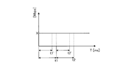
- FIG. 2 is a diagram illustrating an example of a system rate at each time and a time when a normal decoding process is started.
- the horizontal axis represents time T [ms]
- the vertical axis represents system rate [Mbps].
- the system rate continuously changes at a constant X [bps] at each time.
- the terminal performs a decoding process at time t1 and time t2.
- FIG. 3 is a diagram showing an example of the system rate at each time and the timing for starting the encoding process of this embodiment.
- the horizontal axis represents time T [ms]
- the vertical axis represents the system rate [Mbps].
- the system rate continuously changes at a constant X [bps] at each time as in FIG.
- the terminal performs a decoding process at time t1 'earlier than time t1 and at time t2' earlier than time t2.
- the terminal starts the decoding process at t1 'earlier than t1, which is the time to start normal decoding. Thereby, the delay time can be shortened.
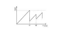
- FIG. 4 is a diagram illustrating an example of a transition of a normal decoder accumulated data amount in the receiving terminal.
- the horizontal axis in FIG. 4 represents time T [ms], and the vertical axis represents the amount of data stored in the buffer [bit].
- t1 indicated on the horizontal axis of FIG. 4 indicates the first decoding start time.
- the first data accumulation time at the terminal is between 0 and t1.
- t2 indicates the second decoding start time.
- the second data accumulation time at the terminal is between t1 and t2.
- the amount of data stored in the buffer increases in proportion to the time until the decoding start time t1.
- the accumulated data amount decreases because decoding is started when the decoding start time t1 is reached. Thereafter, the accumulated data amount increases in proportion to the time until the decoding start time t2.
- the decoder accumulation time which is the time from time 0 to the decoding start time t1, is a waiting time until decoding starts, and is added to the delay time.
- FIG. 5 is a diagram showing an example of the transition of the decoder accumulated data amount of the present embodiment in the receiving terminal.
- the horizontal axis in FIG. 5 represents time T [ms], and the vertical axis represents the amount of data stored in the buffer [bit].
- t1 'described on the horizontal axis of FIG. 5 indicates the first decoding start time in the present embodiment.
- the first decoder accumulation time for the first time at the terminal is between 0 and t1 '.
- t2 ' indicates the second decoding start time in the present embodiment.
- the second decoder accumulation time for the second time at the terminal is between t1 and t2 '. Note that t1 in FIG. 4 corresponds to t1 in FIG. 5, and t2 in FIG. 4 corresponds to t2 in FIG.
- the amount of data stored in the buffer increases in proportion to the time until the decoding start time t1 ′.
- the terminal starts decoding.
- Decryption start time t1 ′ is earlier than time t1.
- the amount of accumulated data increases in proportion to time until time t1 'earlier than time t1, and the terminal starts decoding when time t1' is reached. At this time, the amount of accumulated data decreases.
- the amount of stored data increases in proportion to the time until time t2 'that is earlier than time t2, and the terminal starts decoding when time t2' is reached. At this time, the amount of accumulated data decreases.
- the terminal starts decoding the decoded data when the second decoder storage time shorter than the first decoder storage time has elapsed.
- the decoder accumulation time can be shortened and the delay time can be shortened.
- FIG. 6 is a flowchart for explaining the process flow of the encoding apparatus 100.
- the acquiring unit 121 first acquires operating parameters including the first system rate, the video rate, the audio rate, and the first decoder accumulation time from the storage unit 130 (step S10).
- the second calculation unit 123 calculates a second system rate based on the video rate, the audio rate, and the rate related to multiplexing and AV synchronization data (step S11).
- the first calculation unit 122 calculates a second decoder accumulation time based on the obtained first decoder accumulation time, the obtained first system rate, and the second system rate (step S12).
- the first encoding unit 124 encodes video data
- the second encoding unit 125 encodes audio data
- the transmission unit 126 generates AV synchronization data for synchronizing video data and audio data (step S14).
- the transmission unit 126 multiplexes the encoded video data, the encoded audio data, and the AV synchronization data for transmission to the terminal (step S15).
- the transmission unit 126 determines whether to stop the encoding in the first encoding unit 124 and the second encoding unit 125 (step S16). If the second decoding accumulation time has not elapsed since the start of encoding (step S16 No), the transmission unit 126 continues the encoding and repeats the processing from step S13 to step S15. On the other hand, when the second decoding accumulation time has elapsed (Yes in step S16), the transmission unit 126 stops encoding and transmits the multiplexed data to the terminal (step S17).
- the encoding apparatus 100 encodes data received by the terminal based on a first system rate when the data is encoded and transmitted to the terminal and a second system rate indicating a rate at which the data is reproduced by the terminal. Is provided with a first calculation unit 122 for calculating a decoder accumulation time.
- the encoding apparatus 100 further includes a transmission unit 126 that adds information on the decoder accumulation time to the encoded data and transmits the encoded data to the terminal.
- the encoding apparatus 100 further includes a second calculation unit 123 that calculates a second system rate based on the data and data used to multiplex and synchronize the data. As a result, the second system rate reflecting the actual video rate and audio rate is calculated, and the decoder accumulation time can be obtained accurately using this.
- MPEG-2 is used as the codec, but video data and the like may be compressed by other codecs such as MPEG-1 and MPEG-4.
- FIG. 7 is a diagram illustrating an example of a hardware configuration of the computer 200 according to the encoding device 100.
- the computer 200 includes a CPU 201 that executes various arithmetic processes, an input device 202 that receives data input, and a display device 203 that displays information on a monitor or the like when receiving data input.
- the computer 200 also includes a medium reading device 204 that reads a program and the like from a storage medium, and an interface device 205 for connecting to other devices.
- the computer 200 also includes a RAM 206 that temporarily stores various information and a hard disk device 207. Each device 201 to 207 is connected to a bus 208.
- the hard disk device 207 includes an acquisition unit 121, a first calculation unit 122, a second calculation unit 123, a first encoding unit 124, a second encoding unit 125, and a transmission unit 126 of the control unit 120 illustrated in FIG. A program having the same function is stored.
- the hard disk device 207 corresponds to the storage unit 130 and stores operation parameters such as a system rate, a video rate, an audio rate, and a decoder accumulation time.
- the input device 202 accepts input of various operation parameters.
- the CPU 201 reads out each program stored in the hard disk device 207, develops it in the RAM 206, and executes it to perform various processes.
- these programs serve as the acquisition unit 121, the first calculation unit 122, the second calculation unit 123, the first encoding unit 124, the second encoding unit 125, and the transmission unit 126 illustrated in FIG. Can function.
- the computer 200 may read and execute a program stored in a storage medium readable by the computer 200.
- the storage medium readable by the computer 200 corresponds to, for example, a portable recording medium such as a CD-ROM, a DVD disk, a USB (Universal Serial Bus) memory, a semiconductor memory such as a flash memory, and a hard disk drive.
- the program may be stored in a device connected to a public line, the Internet, a LAN (Local Area Network), etc., and the computer 200 may read and execute the program therefrom.
- Encoder 110 Communication I / F 120 control unit 121 acquisition unit 122 first calculation unit 123 second calculation unit 124 first encoding unit 125 second encoding unit 126 transmission unit 130 storage unit
Abstract
L'invention concerne un dispositif de codage dans lequel une unité (121) d'acquisition acquiert divers paramètres d'exploitation. Une première unité (122) de calcul calcule un temps d'accumulation de deuxième décodeur sur la base d'un rapport entre un deuxième débit de système et un premier débit de système. Une deuxième unité (123) de calcul calcule the deuxième débit de système. Une première unité (124) de codage code des données vidéo au sein de données à distribuer à un terminal. Une deuxième unité (125) de codage code des données audio. Une unité (126) d'émission multiplexe les données vidéo et les données audio codées avec des données de synchronisation AV, et envoie lesdites données au terminal.
Priority Applications (4)
| Application Number | Priority Date | Filing Date | Title |
|---|---|---|---|
| EP13890151.7A EP3026907B1 (fr) | 2013-07-26 | 2013-07-26 | Dispositif, procédé et programme de codage |
| JP2015528092A JP6146471B2 (ja) | 2013-07-26 | 2013-07-26 | 符号化装置、符号化方法、および符号化プログラム |
| PCT/JP2013/070395 WO2015011841A1 (fr) | 2013-07-26 | 2013-07-26 | Dispositif, procédé et programme de codage |
| US15/000,805 US10284865B2 (en) | 2013-07-26 | 2016-01-19 | Encoding device, encoding method, and recording medium |
Applications Claiming Priority (1)
| Application Number | Priority Date | Filing Date | Title |
|---|---|---|---|
| PCT/JP2013/070395 WO2015011841A1 (fr) | 2013-07-26 | 2013-07-26 | Dispositif, procédé et programme de codage |
Related Child Applications (1)
| Application Number | Title | Priority Date | Filing Date |
|---|---|---|---|
| US15/000,805 Continuation US10284865B2 (en) | 2013-07-26 | 2016-01-19 | Encoding device, encoding method, and recording medium |
Publications (1)
| Publication Number | Publication Date |
|---|---|
| WO2015011841A1 true WO2015011841A1 (fr) | 2015-01-29 |
Family
ID=52392917
Family Applications (1)
| Application Number | Title | Priority Date | Filing Date |
|---|---|---|---|
| PCT/JP2013/070395 WO2015011841A1 (fr) | 2013-07-26 | 2013-07-26 | Dispositif, procédé et programme de codage |
Country Status (4)
| Country | Link |
|---|---|
| US (1) | US10284865B2 (fr) |
| EP (1) | EP3026907B1 (fr) |
| JP (1) | JP6146471B2 (fr) |
| WO (1) | WO2015011841A1 (fr) |
Families Citing this family (1)
| Publication number | Priority date | Publication date | Assignee | Title |
|---|---|---|---|---|
| TWI762908B (zh) * | 2020-04-17 | 2022-05-01 | 新唐科技股份有限公司 | 串接式擴增裝置及包含其之串接式系統 |
Citations (4)
| Publication number | Priority date | Publication date | Assignee | Title |
|---|---|---|---|---|
| JPH09298734A (ja) | 1996-04-30 | 1997-11-18 | Matsushita Electric Ind Co Ltd | ビデオオンデマンドシステム |
| JP2000124958A (ja) * | 1998-10-20 | 2000-04-28 | Mitsubishi Electric Corp | 符号化データ切替装置 |
| JP2002084339A (ja) | 2000-07-06 | 2002-03-22 | Matsushita Electric Ind Co Ltd | ストリーミング方法およびそれを実行するシステム |
| JP2011130065A (ja) * | 2009-12-16 | 2011-06-30 | Sony Corp | 送信装置および方法、並びに、受信装置および方法 |
Family Cites Families (3)
| Publication number | Priority date | Publication date | Assignee | Title |
|---|---|---|---|---|
| EP1182875A3 (fr) | 2000-07-06 | 2003-11-26 | Matsushita Electric Industrial Co., Ltd. | Méthode de transmission en continu et système correspondant |
| US7266147B2 (en) * | 2003-03-31 | 2007-09-04 | Sharp Laboratories Of America, Inc. | Hypothetical reference decoder |
| US8218439B2 (en) * | 2004-11-24 | 2012-07-10 | Sharp Laboratories Of America, Inc. | Method and apparatus for adaptive buffering |
-
2013
- 2013-07-26 JP JP2015528092A patent/JP6146471B2/ja active Active
- 2013-07-26 EP EP13890151.7A patent/EP3026907B1/fr active Active
- 2013-07-26 WO PCT/JP2013/070395 patent/WO2015011841A1/fr active Application Filing
-
2016
- 2016-01-19 US US15/000,805 patent/US10284865B2/en active Active
Patent Citations (4)
| Publication number | Priority date | Publication date | Assignee | Title |
|---|---|---|---|---|
| JPH09298734A (ja) | 1996-04-30 | 1997-11-18 | Matsushita Electric Ind Co Ltd | ビデオオンデマンドシステム |
| JP2000124958A (ja) * | 1998-10-20 | 2000-04-28 | Mitsubishi Electric Corp | 符号化データ切替装置 |
| JP2002084339A (ja) | 2000-07-06 | 2002-03-22 | Matsushita Electric Ind Co Ltd | ストリーミング方法およびそれを実行するシステム |
| JP2011130065A (ja) * | 2009-12-16 | 2011-06-30 | Sony Corp | 送信装置および方法、並びに、受信装置および方法 |
Also Published As
| Publication number | Publication date |
|---|---|
| US20160150239A1 (en) | 2016-05-26 |
| JP6146471B2 (ja) | 2017-06-14 |
| JPWO2015011841A1 (ja) | 2017-03-02 |
| EP3026907A4 (fr) | 2016-06-01 |
| EP3026907A1 (fr) | 2016-06-01 |
| EP3026907B1 (fr) | 2018-04-18 |
| US10284865B2 (en) | 2019-05-07 |
Similar Documents
| Publication | Publication Date | Title |
|---|---|---|
| JP7260687B2 (ja) | 送信方法および送信装置 | |
| CN104735470B (zh) | 一种流媒体数据传输方法及装置 | |
| TWI606722B (zh) | 用於減少視訊編碼及解碼中之延遲的方法、系統及電腦可讀取媒體 | |
| JP4837744B2 (ja) | 多重化装置、集積回路、多重化方法、多重化プログラム、多重化プログラムを記録したコンピュータ読み取り可能な記録媒体及び多重化ストリームを記録したコンピュータ読み取り可能な記録媒体 | |
| US10177899B2 (en) | Adapting a jitter buffer | |
| US8996713B2 (en) | Video streaming | |
| CN102118270A (zh) | 一种度量用户体验质量QoE的方法及装置 | |
| CN108476317B (zh) | 音频视频质量推测装置、音频视频质量推测方法以及程序 | |
| EP1941661A1 (fr) | Systeme et procede de gestion de la transmission d'images animees sur un reseau | |
| US20140112636A1 (en) | Video Playback System and Related Method of Sharing Video from a Source Device on a Wireless Display | |
| WO2016008131A1 (fr) | Techniques pour lire séparément des données audio et vidéo dans des réseaux locaux | |
| TWI431986B (zh) | Information processing apparatus and method, and program | |
| JP6146471B2 (ja) | 符号化装置、符号化方法、および符号化プログラム | |
| US9467691B2 (en) | Video system for displaying image data, method and computer program | |
| CN107087210B (zh) | 基于缓存时间判断视频播放状态的方法及终端 | |
| CN114025171A (zh) | 一种视频处理方法、装置、终端设备和存储介质 | |
| CN111836071A (zh) | 一种基于云会议的多媒体处理方法、装置及存储介质 | |
| Jang et al. | Synchronization quality enhancement in 3G-324M video telephony | |
| JPH11313320A (ja) | データ符号化装置および動画像データ符号化方法 |
Legal Events
| Date | Code | Title | Description |
|---|---|---|---|
| 121 | Ep: the epo has been informed by wipo that ep was designated in this application |
Ref document number: 13890151 Country of ref document: EP Kind code of ref document: A1 |
|
| ENP | Entry into the national phase |
Ref document number: 2015528092 Country of ref document: JP Kind code of ref document: A |
|
| WWE | Wipo information: entry into national phase |
Ref document number: 2013890151 Country of ref document: EP |
|
| NENP | Non-entry into the national phase |
Ref country code: DE |