WO2015011745A1 - 光情報記録媒体、光情報記録方法および光情報再生方法 - Google Patents
光情報記録媒体、光情報記録方法および光情報再生方法 Download PDFInfo
- Publication number
- WO2015011745A1 WO2015011745A1 PCT/JP2013/069730 JP2013069730W WO2015011745A1 WO 2015011745 A1 WO2015011745 A1 WO 2015011745A1 JP 2013069730 W JP2013069730 W JP 2013069730W WO 2015011745 A1 WO2015011745 A1 WO 2015011745A1
- Authority
- WO
- WIPO (PCT)
- Prior art keywords
- data
- pattern
- optical information
- information recording
- page
- Prior art date
- Legal status (The legal status is an assumption and is not a legal conclusion. Google has not performed a legal analysis and makes no representation as to the accuracy of the status listed.)
- Ceased
Links
Images



















Classifications
-
- G—PHYSICS
- G11—INFORMATION STORAGE
- G11B—INFORMATION STORAGE BASED ON RELATIVE MOVEMENT BETWEEN RECORD CARRIER AND TRANSDUCER
- G11B7/00—Recording or reproducing by optical means, e.g. recording using a thermal beam of optical radiation by modifying optical properties or the physical structure, reproducing using an optical beam at lower power by sensing optical properties; Record carriers therefor
- G11B7/007—Arrangement of the information on the record carrier, e.g. form of tracks, actual track shape, e.g. wobbled, or cross-section, e.g. v-shaped; Sequential information structures, e.g. sectoring or header formats within a track
- G11B7/00772—Arrangement of the information on the record carrier, e.g. form of tracks, actual track shape, e.g. wobbled, or cross-section, e.g. v-shaped; Sequential information structures, e.g. sectoring or header formats within a track on record carriers storing information in the form of optical interference patterns, e.g. holograms
- G11B7/00781—Auxiliary information, e.g. index marks, address marks, pre-pits, gray codes
-
- G—PHYSICS
- G11—INFORMATION STORAGE
- G11B—INFORMATION STORAGE BASED ON RELATIVE MOVEMENT BETWEEN RECORD CARRIER AND TRANSDUCER
- G11B7/00—Recording or reproducing by optical means, e.g. recording using a thermal beam of optical radiation by modifying optical properties or the physical structure, reproducing using an optical beam at lower power by sensing optical properties; Record carriers therefor
- G11B7/004—Recording, reproducing or erasing methods; Read, write or erase circuits therefor
- G11B7/0065—Recording, reproducing or erasing by using optical interference patterns, e.g. holograms
Definitions
- the present invention relates to a recording medium for recording information using holography and a method for reproducing information on this type of recording medium.
- An optical disk having a recording capacity of about 100 GB has been commercialized, and it is desired to increase the capacity to the same level as that of a hard disk drive in the future. To achieve such a high density, a shorter wavelength of the light source and a higher objective lens are required. A new system different from the conventional high density technology mainly for NA is required.
- the hologram recording technique is generated when a signal light having page data information two-dimensionally modulated by a spatial light modulator is superposed on a reference light having the same wavelength as the signal light inside the recording medium.
- This is a technique for recording information on a recording medium by causing refractive index modulation in the recording medium by an interference fringe pattern.
- the hologram recorded in the recording medium acts like a diffraction grating to generate diffracted light. This diffracted light is reproduced as the same light including the recorded signal light and phase information.
- Regenerated signal light is detected two-dimensionally at high speed using an image sensor such as a CMOS or CCD.
- an image sensor such as a CMOS or CCD.
- the hologram recording technology enables two-dimensional information to be simultaneously recorded on an optical recording medium by one hologram, and further enables the information to be reproduced. Since the page data can be overwritten, large-capacity and high-speed information recording / reproduction can be achieved.
- Patent Document 1 JP-A-2004-272268
- Patent Document 2 JP-A-2004-272268
- This publication discloses a multiplexing method and apparatus in which holograms are spatially multiplexed by partial spatial overlap between adjacent stacks of holograms. Each stack is for example an angle, a wavelength, a phase.
- Another multiplexing technique such as sign, peritropy, or fractal multiplexing can be further taken in.
- An amount equal to the beam waist of the signal light writing the hologram separates the individual stacks of holograms.
- a hologram and a hologram adjacent to the hologram are all read out simultaneously, and the adjacent hologram read out is not transmitted to the camera surface by arranging a filter at the beam waist of the reproduced data, or These undesired reproductions can be found in optical systems with limited angular passbands. Information, it is described that may be filtered. "By the intermediate plane of the angular filter.
- Patent Document 2 JP-T-2008-536158.
- This publication states that “there is a predetermined spare block assigned to each entire data page, each spare block including a known pixel pattern, an area of the data page and a predetermined spare block; By determining the data page position error by calculating the best match between and correcting the data pixels according to the corresponding data page position error at the detector. A process for enabling discrimination of two-dimensional page data is described.
- Patent Document 3 discloses a technique for emphasizing and recording header information in hologram recording.
- Patent Document 3 discloses a technique for emphasizing and recording header information. However, if recording is performed using this technique, light having a higher intensity than other parts is detected at the part where the header information is recorded at the time of reproduction, so when the amount of light detected at the other part is optimized The part of the header information exceeds the detection range of the image sensor, and there is a possibility that proper processing cannot be performed. On the other hand, if the appropriate amount of light is detected in the header information region, the amount of light detected in other regions may be too small to be detected correctly.
- Such information used for checking page data and determining the data format is preferably recorded in a format that allows easier and more accurate determination than user data in order to perform it accurately and in a short processing time.
- an object of the present invention is to provide an optical information recording medium, an optical information recording method, and an optical information reproducing method capable of easily and accurately discriminating page data and identifying a data format.
- FIG. 2 is a block diagram showing a recording / reproducing apparatus of an optical information recording medium for recording and / or reproducing digital information using holography.
- the optical information recording / reproducing device 10 is connected to an external control device 91 via an input / output control means 90.
- the optical information recording / reproducing apparatus 10 receives the information signal to be recorded from the external control device 91 by the input / output control means 90.
- the optical information recording / reproducing apparatus 10 transmits the reproduced information signal to the external control apparatus 91 by the input / output control means 90.
- the optical information recording / reproducing apparatus 10 includes a pickup 11, a reproduction reference light optical system 12, a cure optical system 13, a disk rotation angle detection optical system 14, and a rotation motor 50.
- the optical information recording medium 1 is a rotation motor. 50 can be rotated.
- the pickup 11 plays a role of irradiating the optical information recording medium 1 with reference light and signal light and recording digital information on the recording medium using holography.
- the information signal to be recorded is sent to the spatial light modulator in the pickup 11 by the controller 89 via the signal generating means 86, and the signal light is modulated by the spatial light modulator.
- the reproduction reference light optical system 12 When reproducing the information recorded on the optical information recording medium 1, the reproduction reference light optical system 12 generates a light wave that causes the reference light emitted from the pickup 11 to enter the optical information recording medium in a direction opposite to that during recording. Generate. Reproduction light reproduced by the reproduction reference light is detected by a photodetector (to be described later) in the pickup 11, and the signal is reproduced by the signal processing means 85.
- the irradiation time of the reference light and the signal light applied to the optical information recording medium 1 can be adjusted by controlling the opening / closing time of the shutter in the pickup 11 by the controller 89 via the shutter control means 87.
- the cure optical system 13 plays a role of generating a light beam used for pre-cure and post-cure of the optical information recording medium 1.
- Precure is a pre-process for irradiating a predetermined light beam in advance before irradiating the desired position with reference light and signal light when recording information at a desired position in the optical information recording medium 1.
- Post-cure is a post-process for irradiating a predetermined light beam after recording information at a desired position in the optical information recording medium 1 so that additional recording cannot be performed at the desired position.
- the disk rotation angle detection optical system 14 is used to detect the rotation angle of the optical information recording medium 1.
- a signal corresponding to the rotation angle is detected by the disk rotation angle detection optical system 14, and the controller 89 uses the detected signal to control the disk rotation motor control means.
- the rotation angle of the optical information recording medium 1 can be controlled via 88.
- a predetermined light source driving current is supplied from the light source driving means 82 to the light sources in the pickup 11, the cure optical system 13, and the disk rotation angle detection optical system 14, and each light source emits a light beam with a predetermined light quantity. Can do.
- the pickup 11 and the disc cure optical system 13 are provided with a mechanism capable of sliding the position in the radial direction of the optical information recording medium 1, and position control is performed via the access control means 81.
- the recording technology using the principle of angle multiplexing of holography tends to have a very small tolerance for the deviation of the reference beam angle.
- a mechanism for detecting the deviation amount of the reference beam angle is provided in the pickup 11, a servo control signal is generated by the servo signal generation unit 83, and the deviation amount is corrected via the servo control unit 84. It is necessary to provide a servo mechanism for this purpose in the optical information recording / reproducing apparatus 10.
- the pickup 11, the cure optical system 13, and the disk rotation angle detection optical system 14 may be simplified by combining several optical system configurations or all optical system configurations into one.
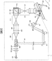
- FIG. 3 shows a recording principle in an example of a basic optical system configuration of the pickup 11 in the optical information recording / reproducing apparatus 10.
- the light beam emitted from the light source 301 passes through the collimator lens 302 and enters the shutter 303.
- the shutter 303 When the shutter 303 is open, after the light beam passes through the shutter 303, the optical ratio of the p-polarized light and the s-polarized light becomes a desired ratio by the optical element 304 composed of, for example, a half-wave plate.
- the optical element 304 composed of, for example, a half-wave plate.
- the light is incident on a PBS (Polarization Beam Splitter) prism 305.
- PBS Polarization Beam Splitter
- the light beam that has passed through the PBS prism 305 functions as signal light 306, and after the light beam diameter is expanded by the beam expander 308, the light beam passes through the phase mask 309, the relay lens 310, and the PBS prism 311 and passes through the spatial light modulator 312. Is incident on.
- the signal light to which information is added by the spatial light modulator 312 reflects the PBS prism 311 and propagates through the relay lens 313 and the spatial filter 314. Thereafter, the signal light is condensed on the optical information recording medium 1 by the objective lens 315.
- the light beam reflected from the PBS prism 305 functions as reference light 307 and is set to a predetermined polarization direction according to recording or reproduction by the polarization direction conversion element 316 and then galvano- lated via the mirror 317 and the mirror 318. Incident on the mirror 319. Since the angle of the galvanometer mirror 319 can be adjusted by the actuator 320, the incident angle of the reference light incident on the optical information recording medium 1 after passing through the lens 321 and the lens 322 can be set to a desired angle. In order to set the incident angle of the reference light, an element that converts the wavefront of the reference light may be used instead of the galvanometer mirror.
- the signal light and the reference light are incident on the optical information recording medium 1 so as to overlap each other, whereby an interference fringe pattern is formed in the recording medium, and information is recorded by writing this pattern on the recording medium.
- the incident angle of the reference light incident on the optical information recording medium 1 can be changed by the galvanometer mirror 319, recording by angle multiplexing is possible.
- holograms corresponding to each reference beam angle are called pages, and a set of pages angle-multiplexed in the same area is called a book. .
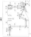
- FIG. 4 shows a reproduction principle in an example of a basic optical system configuration of the pickup 11 in the optical information recording / reproducing apparatus 10.
- the reference light is incident on the optical information recording medium 1 as described above, and the light beam transmitted through the optical information recording medium 1 is reflected by the galvanometer mirror 324 whose angle can be adjusted by the actuator 323. By doing so, the reproduction reference light is generated.
- the reproduction light reproduced by the reproduction reference light propagates through the objective lens 315, the relay lens 313, and the spatial filter 314. Thereafter, the reproduction light passes through the PBS prism 311 and enters the photodetector 325, and the recorded signal can be reproduced.
- the photodetector 325 for example, an image sensor such as a CMOS image sensor or a CCD image sensor can be used. However, any element may be used as long as page data can be reproduced.
- FIG. 6 shows an operation flow of recording and reproduction in the optical information recording / reproducing apparatus 10.
- a flow relating to recording / reproduction using holography in particular will be described.
- FIG. 6A shows an operation flow from when the optical information recording medium 1 is inserted into the optical information recording / reproducing apparatus 10 until preparation for recording or reproduction is completed
- FIG. FIG. 6C shows an operation flow until information is recorded on the information recording medium 1
- FIG. 6C shows an operation flow until the information recorded on the optical information recording medium 1 is reproduced from the ready state.
- the optical information recording / reproducing apparatus 10 discriminates whether or not the inserted medium is a medium for recording or reproducing digital information using holography, for example. (602).
- the optical information recording / reproducing apparatus 10 reads control data provided on the optical information recording medium (603). ), For example, information relating to the optical information recording medium and information relating to various setting conditions during recording and reproduction, for example.
- the operation flow from the ready state to recording information is as follows. First, data to be recorded is received (611), and information corresponding to the data is received from the spatial light modulator in the pickup 11. Send to.
- the access control means 81 is controlled to position the pickup 11 and the cure optical system 13 at predetermined positions on the optical information recording medium.
- the optical information recording medium 1 has address information, it reproduces the address information, checks whether it is positioned at the target position, and calculates the amount of deviation from the predetermined position if it is not positioned at the target position. And repeat the positioning operation.
- a predetermined region is pre-cured using the light beam emitted from the cure optical system 13 (614), and page data generation processing (617) including main data generation (615) and page header addition (616) is performed, and pickup is performed.
- Data is recorded using the reference light and the signal light emitted from 11 (618).
- post cure is performed using the light beam emitted from the cure optical system 13 (619). Data may be verified as necessary.
- the main data is a part that occupies most of the page data, and mainly stores user data.
- a table showing the correspondence between the logical address handled by the external control device 91 and the position of each page data in the optical information recording medium 1, or replacement of page data that has become difficult to reproduce due to a defect You may make it store the replacement position list
- the page header is an area provided on the page data for storing information such as the type and data format of the data recorded in the page data and the address for identifying the multiple recorded pages. Is provided separately from the recording area on the page data.
- the operation flow from the ready state to the reproduction of recorded information is as follows.
- the access control means 81 is controlled, and the pickup 11 and the reproduction reference light are reproduced.
- the position of the optical system 12 is positioned at a predetermined position on the optical information recording medium.
- the optical information recording medium 1 has address information, it reproduces the address information, checks whether it is positioned at the target position, and calculates the amount of deviation from the predetermined position if it is not positioned at the target position. And repeat the positioning operation.
- FIG. 9 shows a data processing flow during recording and reproduction.
- FIG. 9A shows the two-dimensional data on the spatial light modulator 312 after the recording data reception processing 611 in the input / output control means 90.
- FIG. 9B shows a recording data processing flow in the signal generation means 86 until conversion.
- FIG. 9B shows the process up to the reproduction data transmission process 624 in the input / output control means 90 after the two-dimensional data is detected by the photodetector 325.
- the reproduction data processing flow in the signal processing means 85 is shown.
- the data processing during recording will be described with reference to FIG.
- the processing from 901 to 906 corresponds to the internal processing of the main data generation (615) in the processing of FIG.
- the signal generation means 81 receives user data (901), it is divided into a plurality of data strings and each data string is converted to CRC (902) so that error detection during reproduction can be performed, and the number of on pixels and the number of off pixels are substantially equal.
- the data string is scrambled (903) to add a pseudo random number data string, and then error correction coding such as a Reed-Solomon code (904) is performed so that error correction can be performed during reproduction. )I do.
- the two-dimensional data (905) is configured by arranging the error correction encoded data string according to a predetermined rule.
- a modulation process such as run-length limited modulation may be added in the process 905.
- a marker serving as a reference for image position detection and image distortion correction at the time of reproduction is added to the two-dimensional data thus configured (906), and a page header is added (616) to the spatial light modulator 312. Data is transferred (907).
- the processing from 912 to 919 corresponds to the internal processing of data reproduction (624) in the processing of FIG.
- the image data detected by the photodetector 325 is transferred to the signal processing means 85 (911), and the page header is discriminated from the detected image data (623), and the data stored in the page header is acquired.
- the image position is detected with reference to the marker included in the image data (912), and distortion such as the tilt, magnification, and distortion of the image is corrected (913), and then binarization processing (914) is performed.
- error correction processing (917) is performed to remove the parity data strings.
- descrambling processing (918) is performed, CRC error detection processing (919) is performed and CRC parity is deleted, and then user data is transmitted (920) via the input / output control means 90. If it can be expected that the image position detection by the marker (912) can be performed more easily than the determination of the page header (623), the order of these processes is changed, and the image position detection result by the marker is used for the page. A header search may be performed.
- FIG. 7 is a block diagram of the signal generation means 86 of the optical information recording / reproducing apparatus 10.
- the input / output control means 90 When the input of user data is started to the output control means 90, the input / output control means 90 notifies the controller 89 that the input of user data has been started. In response to this notification, the controller 89 instructs the signal generation unit 86 to record one page of data input from the input / output control unit 90 and provides the header pattern generation unit 710 with information to be stored in the page header. A processing command from the controller 89 is notified to the sub-controller 701 in the signal generation means 86 via the control line 708. Upon receiving this notification, the sub-controller 701 controls each signal processing means via the control line 708 so that the signal processing means are operated in parallel.
- the memory control unit 703 is controlled to store the user data input from the input / output control unit 90 via the data line 709 in the memory 702.
- the CRC calculation means 704 performs control to convert the user data into CRC.
- the scrambler 705 scrambles the CRC-converted data by adding a pseudo-random data sequence
- the error correction encoder 706 performs error correction encoding by adding a parity data sequence.
- a recording marker of the main data portion of the page data is generated by adding a reference marker at the time of reproduction, and stored in the memory 702.
- the header pattern generation unit 711 generates a page header recording pattern based on the information stored in the page header input from the controller 89 and stores it in the memory 702.
- the pickup interface unit 707 reads the recording pattern of the main data and the recording pattern of the page header from the memory 702 in the order of the two-dimensional data on the spatial light modulator 312, and causes the spatial light modulator 312 in the pickup 11 to read it. Transfer two-dimensional data.
- FIG. 8 is a block diagram of the signal processing means 85 of the optical information recording / reproducing apparatus 10.
- the controller 89 instructs the signal processing means 85 to reproduce the data for one page input from the pickup 11.
- a processing command from the controller 89 is notified to the sub-controller 801 in the signal processing means 85 via the control line 811.
- the sub-controller 801 controls each signal processing unit via the control line 811 so that the signal processing units operate in parallel.
- the memory control unit 803 is controlled to store the image data input from the pickup 11 via the pickup interface unit 810 via the data line 812 in the memory 802.
- the header pattern decoding unit 813 decodes the data stored in the page header, and the detected page data identification information is the page data to be reproduced.
- the image position detection unit 809 performs control for detecting a marker from the image data stored in the memory 802 and extracting an effective data range.
- the image distortion correction unit 808 performs distortion correction such as image inclination, magnification, and distortion using the detected marker, and controls to convert the image data into the expected two-dimensional data size.
- Each bit data of a plurality of bits constituting the size-converted two-dimensional data is binarized by the binarizing means 807 to determine “0” or “1”, and the data is arranged on the memory 802 in the order of the output of the reproduction data. Control to store.
- the error correction means 806 corrects the error included in each data string
- the scramble release means 805 releases the scramble to add the pseudo random number data string
- the CRC calculation means 804 introduces an error in the user data on the memory 802. Check not included. Thereafter, the user data is transferred from the memory 802 to the input / output control means 90.
- FIG. 10A shows the positions of the signal light and the page data on the pixel surface of the spatial light modulator 312 and the position of the page header area in the page data.
- Reference numeral 1001 denotes a main data area
- reference numeral 1002 denotes a page header area
- reference numeral 1003 denotes a spatial light modulator pixel
- reference numeral 1004 denotes a signal light optical axis position.
- the pixels 1003 of the spatial light modulator are arranged in a matrix along two orthogonal directions as shown in the enlarged view of FIG. 10A.
- the respective directions are defined as an X direction and a Y direction.
- the pixel sizes of the spatial light modulator pixel 1003 in these directions are denoted by ⁇ X and ⁇ Y.
- the signal light optical axis position 1004 is a point where the optical axis of the signal light 314 directed to the optical information recording medium via the relay lens 313, the spatial filter 314, and the objective lens 315 is located on the pixel surface of the spatial light modulator 312. .
- the side view represents a cross-sectional view of the signal light 306, the relay lens 313, and the spatial filter 314 in the X and Y directions, and the opening sizes of the spatial filter 314 are denoted as Xspfs and Yspf, respectively.
- Xspfs the opening sizes of the spatial filter 314
- Yspf the opening sizes of the spatial filter 314
- the main data area 1001 is an area where user data is mainly recorded in the page data.
- the main data area 1001 is centered on the signal light optical axis position 1004 on the pixel surface of the spatial light modulator 312 and is shown in FIG.
- the objective lens 315 is a circle having a diameter substantially equal to the smaller one of the effective diameters of the objective lens 315. By making such a circular region, the effective diameter region of the relay lens 313 and the objective lens 315 can be utilized without waste, and the maximum data size that can be stored in a single page data can be obtained. . In the case where the loss of data size is allowed, it does not necessarily have to be circular.
- the page header area 1002 is an area for recording a page header for storing information such as the type and data format of data recorded in the page data and an address for identifying the multiple recorded pages. It is arranged on a straight line in the X direction or the Y direction passing through the axial position 1004, and is a rectangular region having the direction of these straight lines as a long side.
- FIG. 10A shows an example in which page header regions 1002 are provided in both the X direction and the Y direction.
- FIG. 10B is an example provided only in the X direction.
- FIG. 10C is an example provided only in the Y direction.
- FIG. 10D is an example in which two page header areas 1002 are provided only in the X direction, and a plurality of page header areas 1002 divided in this way may be provided.
- the detection image is less distorted during reproduction because it is less affected by the aberration of the optical component than when the page header region 1002 is concentrated in the periphery of the page data. An effect of enabling acquisition of a small page header image is obtained.
- the page header in this embodiment is recorded as a bit pattern arranged one-dimensionally in the long side direction of the page header area 1002 as described later.
- the bandwidth of the spatial frequency of the page data image detected at the time of reproduction is proportional to the aperture size of the spatial filter 314, the smaller the product of the pixel size of the spatial light modulator 312 and the aperture size of the spatial filter 314, The ratio of the spatial frequency band to the spatial sampling frequency (the reciprocal of the pixel interval of the spatial light modulator 312) decreases, and the amount of intersymbol interference between pixels increases.
- page header regions 1002 are provided in both directions as shown in FIG. 10A. If the X direction and the Y direction are significantly different, it is preferable to provide a page header area 1002 only in one direction where the product value is small, as shown in FIGS. 10B, 10C, and 11D.
- modulating the minimum continuous length of at least one of on and off pixels along one direction of the page data to reduce the spatial frequency bandwidth in this direction and This is the case when applying the spatial filter 314 having a smaller aperture size than the other direction.
- Such a technique is disclosed in, for example, Japanese Patent Application Laid-Open No. 2010-003358.
- the minimum continuous length of on-pixels and off-pixels in the X direction is limited to reduce the spatial frequency in the X direction and the aperture size of the spatial filter 314 in the X direction is shorter than the Y direction, only the Y direction
- the page header region 1002 may be provided only in the X direction.
- the direction in which the opening size is long makes it easy to read the data in the page header region 1002, while the direction in which the opening size is short is difficult to read.
- the page header region can be accurately reproduced by configuring in this way. In addition, a large amount of main data area can be secured.
- FIG. 1 shows an example of the pattern of the page header area 1002.
- Fig. 1 (a) is an example of a bit pattern representing information of each bit of data to be stored.
- Reference numeral 101 denotes a clock pattern unit
- 102 denotes a data pattern unit.
- the squares in the figure represent pixels of the spatial light modulator 312. Each pixel modulates light into two polarities, on and off. Pixels shown in white are on-pixels, and pixels shown in black are off-pixels.
- the bit pattern representing each bit has a clock pattern portion 101 and a data pattern portion 102, which are close to each other in the short side direction of the page header area 1002.
- the bit pattern representing “1” and the bit pattern representing “0” are distinguished by the data pattern unit 102, and the clock pattern unit 101 is common.
- the data pattern part is divided into two equal parts in the long side direction of the page header area 1002, and different polarities are given to the pixels in each area so that a constant luminance level is maintained regardless of the bit information to be recorded. ing.
- the clock pattern portion 101 has two regions each corresponding to 1/4 of both ends (corresponding to two pixels in FIG. 1A) and a central portion (FIG. 1A) in the long side direction of the page header region 1002. ) Is equivalent to 4 pixels in the middle), and the central part and the peripheral part have different polarities.
- Fig. 1 (b) is an example of a data string of a plurality of bits using the bit pattern shown in Fig. 1 (a).
- Reference numeral 103 denotes a clock pattern
- reference numeral 104 denotes a data pattern.
- the clock pattern 103 has the same period as that of the bit pattern (corresponding to 8 pixels in FIGS. 1A and 1B), and the on-pixel portion and the off-pixel portion have the same width (FIG. 1). (equivalent to the 8 pixels in (b)).
- the data pattern 104 is composed of an on-pixel area and an off-pixel area having the same width as that of the bit pattern (corresponding to 8 pixels in FIGS. 1A and 1B) or a half of the width. Is done. Further, the polarity change point of the data pattern 104 is located at the center between successive polarity change points of the clock pattern 103 with respect to the long side direction of the page header area 1002.
- FIG. 1C shows the intensity distribution of the signal light obtained from the clock pattern 103 and the data pattern 104 shown in FIG. 1B, with the position on the straight line along the long side direction of the page header area 1002 as the horizontal axis. It is the shown schematic. Here, the signal intensity obtained from the on-pixel is illustrated as being greater than the signal intensity obtained from the off-pixel.
- 105 is a clock pattern detection signal
- 106 is a data pattern detection signal.
- the vertical axis represents the signal intensity, and the center level of the signal is shown as an intersection with the horizontal axis.
- the intersection between the plot line of each detection signal and the horizontal axis corresponds to the polarity change point in FIG. In the following, the intersection of the horizontal axis and the plot line is referred to as a zero cross point.
- the zero cross points of the data pattern detection signal 106 are also located at equal intervals in correspondence with the polarity change points of the data pattern 104 being located at the center between successive polarity change points of the clock pattern 103. It is located at the center between the zero cross points of the pattern detection signal 105.
- the zero cross position of the clock pattern is discriminated from the clock pattern detection signal 105, the signal intensity of the data pattern detection signal 106 at the obtained zero cross position is subsequently detected and compared with the center level. It can be expected to obtain an effect that the discrimination can be performed easily and accurately.
- the center level can be obtained by using a low-pass filter that cuts off the repetitive spatial frequency with respect to the clock pattern detection signal 105. Further, the center level of the clock pattern detection signal thus obtained is used. Can be used for pattern discrimination of adjacent data pattern detection signals 106. Further, the peak level and bottom level of the clock pattern detection signal can be detected from the central signal level between the zero cross positions of the clock pattern detection signal.
- the page header area 1002 from the page data detected by the photodetector 325 is determined.
- the clock pattern 103 and the data pattern 104 from the page header area 1002 it is necessary to determine an appropriate position in the short side direction of the page header area 1002. Therefore, at least two patterns called position reference markers are provided along the long side direction of the page header region 1002 below.
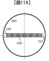
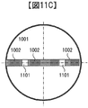
- FIG. 11A, FIG. 11B, FIG. 11C, FIG. 11D, FIG. 11E, and FIG. 11F show examples of arrangement positions of position reference markers, and 1101 represents a position reference marker in each.
- FIG. 11A shows an example in which position reference markers 1101 are arranged at both ends of one page header area 1002 arranged in one direction.
- FIG. 11B is an example in which position reference markers 1101 are arranged at both ends and the center of one page header area 1002 arranged in one direction. If the page header area 1002 is largely distorted and deviates from the straight line connecting the two position reference markers 1101 provided at both ends at the center, the reference position marker 1101 is added to the center in this way and detection described later By performing the processing, the detection accuracy of the pattern in the page header area can be improved. In addition, as long as an area for storing page header information can be secured, not only the central portion but also a larger number of reference position markers 1101 may be provided.
- FIG. 11C is an example in which the position reference markers 1101 are arranged at two locations in the middle of one page header area 1002 arranged in one direction. If the aberration of the optical component or the distortion of the disc is excessively applied, there may be a case where a sufficient amount of detected light cannot be obtained at the periphery of the detected image of page data during reproduction. By providing the position reference marker 1101 as shown in FIG. 11C, the position reference marker 1101 can be detected even in such a case.
- FIG. 11D is an example in which position reference markers 1101 are arranged at both ends of two page header areas 1002 arranged in one direction.
- the two page header regions 1002 are divided as shown in FIG. The page header can be detected accurately and easily in the same manner as in the above example.
- FIG. 11E is an example in which a position reference marker 1101 is arranged in the middle between two page header areas 1002 arranged in one direction.
- the position reference markers 1101 are provided at both ends of the two page header regions 1002.
- the page header can be detected accurately and easily.
- FIG. 11F shows an example in which page header areas 1002 are arranged in two directions.
- the position reference markers 1101 are arranged at the center and both ends, and the center portion is used in two directions.
- two or more position reference markers 1101 are provided along each direction. If so, another pattern may be arranged in the central portion.
- the polarity inversion of the clock pattern unit 101 during reproduction and the position on the photodetector 325 where the position reference marker 1101 is detected and the signal intensity By performing the two-dimensional linear interpolation process using, the distortion and intensity unevenness of the entire page data image detected by the photodetector 325 can be estimated and corrected. .
- FIG. 12A is a configuration example of the position reference marker 1101. It consists of a rectangular central part and a peripheral part surrounding the central part, and the central part and the peripheral part are composed of pixels of different polarities.
- FIG. 12A shows an example in which the peripheral portion is an on-pixel and the central portion is an off-pixel, the reverse may be possible.
- the size in the short side direction of the page header area 1002 in the center is determined to be about half the sum of the clock pattern size and the data pattern size in the same direction.
- FIG. 12B shows the positional relationship between the position reference marker 1101 and the page header area 1002.
- 1202 is a marker center upper boundary line
- 1203 is a wrinkle marker center lower boundary line.
- the marker center upper boundary line 1202 and the marker center lower boundary line 1203 connect the upper and lower boundaries of the center part of the two position reference markers 1101 arranged with respect to the page header region 1002 in the same direction. It is a straight line.
- the position reference marker 1101 is arranged so that the upper and lower sides of the center portion are positioned at the center of each of the clock pattern 103 and the data pattern 104 in the short side direction of the page header area 1002. With this positional relationship, the marker center upper boundary line 1202 and the marker center lower boundary line 1203 become the respective center positions in the short side direction of the page header area 1002 of the clock pattern 103 and the data pattern 104. .
- the page header for detecting the clock pattern 103 and the data pattern 104 by detecting the center part of the two position reference markers 1101 and determining the marker center upper boundary line 1202 and the marker center lower boundary line 1203. An appropriate position in the region short side direction can be determined.
- the central portion and the peripheral portion of the position reference marker 1101 are occupied by pixels having opposite polarities. If the region is within the position reference marker 1101, the central portion and the peripheral portion can be easily distinguished by the polarity of the pixel. It is. Therefore, the central portion can be easily detected by searching within the position reference marker 1101 as a range by ensuring the peripheral region range sufficiently large with respect to the magnitude of the shift / distortion of the detection image during reproduction. It becomes.
- the clock pattern 101 has a certain periodicity, it is possible to interpolate from the position around the detection failure part even when a part of the clock pattern 101 is not detected correctly in many cases. There is a possibility that erroneous detection or omission of the pattern occurs and the data detected from the header is discriminated from the correct bit position.
- synchronization patterns are provided at regular intervals as patterns other than “1” ⁇ “0”, and bit position deviation is corrected with reference to the detection position of the synchronization pattern. You should be able to do it.
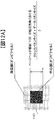
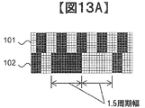
- FIG. 13A shows an example of a synchronization pattern.
- the clock pattern unit 101 arranges the clock pattern 103 and a pattern ensuring the continuity of the cycle and phase.
- the data pattern unit 102 an on-pixel pattern and an off-pixel pattern having a width 1.5 times the period of the clock pattern 103 are arranged.
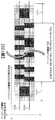
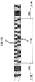
- FIG. 13B shows an example in which the synchronization pattern shown in FIG. 13A is inserted into the page header area 1002, and the data portion in the figure is a part where bit patterns representing information of “1” or “0” are arranged.
- the synchronization unit is a part where the synchronization pattern shown in FIG. 13A is arranged.
- the clock pattern 103 has a pattern with a uniform period without distinction between the data part and the synchronization part, and the data pattern 104 has an on-pixel pattern and an off-pixel pattern with a 1.5 period width only in the synchronization part. .
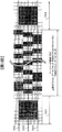
- FIG. 14A shows another example of the synchronization pattern.
- the pattern has a three-cycle width centered on a portion having a width corresponding to 1.5 cycles of the clock pattern 103 with respect to the long-axis direction of the page header region 1002, and the short-axis direction of the page header region 1002 Unlike the example shown in FIGS. 13A and 13B, the clock pattern unit 101 and the data pattern unit 102 are uniform without distinction.
- FIG. 14B shows an example in which the example of the synchronization pattern shown in FIG. 14A is inserted into the page header area 1002, and the data part in the figure is a part where bit patterns representing information of “1” or “0” are arranged. is there.
- the synchronization unit is a part where the synchronization pattern shown in FIG. 14A is arranged.
- the synchronization pattern can be determined according to one condition.
- the width of the synchronization pattern is exactly an integral multiple of the cycle of the clock pattern. By selecting this, it is possible to interpolate the clock pattern.
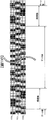
- FIG. 25A shows still another example of the synchronization pattern.
- the major axis direction is the same width as the position reference marker 1101 and larger than the 0.5 or 1 clock cycle length pattern that forms the data pattern and the clock pattern.
- This is a pattern of an integer (3 in the figure) clock period width having a rectangular central part with a size of (2 clock period length in the figure) and surrounded by pixels having a polarity different from that of the central part.
- FIG. 25B shows an example in which the synchronization pattern shown in FIG. 25A is inserted into the page header area 1002, and the data portion in the figure is a part where bit patterns representing information of “1” or “0” are arranged.
- the synchronization unit is a part where the synchronization pattern shown in FIG. 25A is arranged.
- a synchronization pattern When such a synchronization pattern is applied, it is possible to discriminate the synchronization pattern by detecting the central part based on the polarity change positions in the short axis and long axis directions. Further, regarding the length of the page header region 1002 in the major axis direction, if the length of the data portion is sufficiently larger than the width of the synchronization portion, the clock pattern interrupted by the synchronization portion can be interpolated. Further, when the synchronization pattern shown in FIG.
- the position in the minor axis direction for detecting the polarity change point in the minor axis direction at the center and discriminating between the clock pattern and the data pattern, like the position reference marker 1101. Can be used to determine the marker center upper boundary line 1202 and the marker center lower boundary line 1203 for determining the position of the marker.
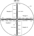
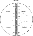
- each page header area 1002 is set to Header1, Header2, Header3, and Header4.
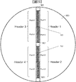
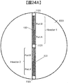
- the same information is stored in these four page header areas, and the data is quadrupled, but the arrangement order of the stored data is different in each area. That is, the data pattern area of these four page header areas is further divided into four parts, and the data to be stored is also divided into Part A, B, C, D, and Part A in Headers 1 to 4 , B, C, and D are arranged as follows. An example satisfying this arrangement order is shown in FIGS. 15A and 16A.
- the header is arranged in the order of Part ABCD in the order from the center of the page data (Header 1 in FIG. 16A)
- the order of arrangement in the remaining three headers is Part DCBA (Header 2 in FIG. 16A), Part C-A-D-B (Header 3 in FIG. 16A), Part B-D-A-C (Header 4 in FIG. 16A).
- FIG. 15B shows the arrangement order from the center of Part A, B, C, D in each Header in the arrangement of FIG. 15A, and the arrangement order from the center in the four Headers is different for all Part. It is shown.
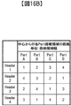
- FIG. 16B shows the arrangement order from the center of Part A, B, C, D in each Header in the arrangement of FIG. 16A, and the arrangement order from the center in the four Headers for all Part. It is shown that they are different from each other. This means that there is no bias with respect to the arrangement of each Part, and there is a small risk that a specific Part will occur in the determination in all four Headers.
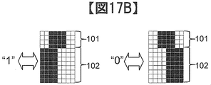
- FIG. 17 shows an example of the pattern of the page header area 1002 in this embodiment.
- ⁇ in the figure represents pixels of the spatial light modulator 312. Each pixel modulates light into two polarities, on and off. Pixels shown in white are on-pixels, and pixels shown in black are off-pixels.
- FIG. 17C schematically shows the pattern of the page header area 1002 in this embodiment, and the short side of the page header area 1002 with respect to the clock pattern 103 having a constant period with respect to the long side direction of the page header area 1002.
- Two rows of data patterns, data pattern A (1704) and data pattern B (1705), are arranged close to each other in the direction.
- FIG. 17A shows a bit pattern corresponding to 1-bit data in data pattern A (1704).
- FIG. 17B shows a bit pattern corresponding to 1-bit data in data pattern B (1705). Both of these are composed of a clock pattern unit 101 and a data pattern unit 102. The positional relationship between the data pattern A (1704) and the data pattern B (1705) is adjacent to the clock pattern 103. Different. That is, in the bit pattern of the data pattern A (1704), the clock pattern unit 101 is positioned below the data pattern unit 102 in the figure, and in the bit pattern of one data pattern B (1705), the data pattern unit The clock pattern unit 101 is located on the upper side in FIG.
- the bit pattern representing “1” and the bit pattern representing “0” are distinguished by the data pattern unit 102 and The pattern unit 101 is common.
- the data pattern part is divided into two equal parts in the long side direction of the page header area 1002, and different polarities are given to the pixels in each area so that a constant luminance level is maintained regardless of the bit information to be recorded.
- the clock pattern portion 101 is divided into two regions each having a quarter of both ends (corresponding to two pixels in FIG. 1A) and a central portion (FIG. 1A) with respect to the long side direction of the page header region 1002. ) (Corresponding to 4 pixels in the above), and the central part and the peripheral part have different polarities. Note that the width in the short side direction of the page header area 1002 of the data pattern portion is the same for both the bit patterns of the data pattern A and the data pattern B.
- the pattern shown in FIG. 17C is obtained by arranging the bit patterns of data pattern A and data pattern B shown in FIGS. 17A and 17B corresponding to the data stored in the respective areas.
- the clock pattern 103 in FIG. 17C has the same cycle as the bit pattern width (corresponding to 8 pixels in FIGS. 17A, 17B, and 17C), and the widths of the on-pixel portion and the off-pixel portion are the same (in FIG. 17C). Equivalent to 8 pixels).
- Data pattern A (1704) and data pattern B (1705) are both on-pixels having the same width as the bit pattern (equivalent to 8 pixels in FIGS. 17A, 17B, and 17C) or half the width thereof. It consists of a region and an off-pixel region. Further, the polarity change points of the data pattern A (1704) and the data pattern B (1705) are both located at the center between successive polarity change points of the clock pattern 103 with respect to the long side direction of the page header region 1002.
- the discrimination between the data pattern A (1704) and the data pattern B (1705) in the header pattern of this embodiment shown in FIG. 17C is the same as the discrimination of the data pattern 104 in the example of FIG. 1 from the clock pattern detection signal 105.
- the clock pattern has periodicity, when a missing portion is generated, it can be interpolated from the surrounding positional relationship as in the example of FIG.
- the position reference markers may be arranged as shown in FIGS. 11A, 11B, 11C, 11D, and 11E.
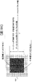
- the position reference marker for the header pattern of this embodiment, and the position in the short side direction of the page header area 1002 for detecting the clock pattern 103, the data pattern A (1704), and the data pattern B (1705) are determined by the position reference marker.
- the method will be described with reference to FIG.
- Reference numeral 1801 denotes a position reference marker
- 1802 denotes a marker center upper boundary line
- 1803 denotes a marker center center line
- 1804 denotes a marker center lower boundary line.
- FIG. 18A is a configuration example of the position reference marker 1801. It consists of a rectangular central part and a peripheral part surrounding the central part, and the central part and the peripheral part are composed of pixels of different polarities.
- FIG. 18A shows an example in which the peripheral portion is an on-pixel and the central portion is an off-pixel, the reverse is also possible.
- the size of the page header area 1002 in the central portion in the short side direction is such that the width of the clock pattern 103 is added to half the sum of the widths of the data pattern A (1704) and the data pattern B (1705) in the same direction. Stipulated in
- FIG. 18B shows the positional relationship between the position reference marker 1801 and the page header area 1002.
- the marker center upper boundary line 1802 and the marker center lower boundary line 1804 connect the upper and lower boundaries of the center part of the two position reference markers 1801 arranged with respect to the page header region 1002 in the same direction. It is a straight line.
- the position reference marker 1801 is arranged so that the upper and lower sides of the center portion are positioned in the vicinity of the respective centers of the data pattern A (1704) and the data pattern B (1705) in the short side direction of the page header area 1002. . With such a positional relationship, the marker center upper boundary line 1802 and the marker center lower boundary line 1804, and the center positions of the clock pattern 103 and the data pattern 104 in the short-side direction of the page header area 1002 are obtained.
- the detection of the data pattern A (1704) and the data pattern B (1705) is performed by detecting the center of the two position reference markers 1801 and determining the marker center upper boundary line 1802 and the marker center lower boundary line 1804. It is possible to determine an appropriate position in the direction of the short side of the page header area for performing. Further, by obtaining a marker center part center line 1803 that bisects between the marker center upper boundary line 1802 and the marker center lower boundary line 1804, the page header area short side direction for detecting the clock pattern 103 is obtained.
- the center part and the peripheral part of the position reference marker 1801 are occupied by pixels having opposite polarities. If the region is within the position reference marker 1801, the center part depends on the polarity of the pixel. And the peripheral part can be easily distinguished. Therefore, the central portion can be easily detected by searching the position reference marker 1801 as a range by ensuring the peripheral region range sufficiently large with respect to the magnitude of the shift / distortion of the detected image during reproduction. it can.
- FIG. 19A shows an example of a synchronization pattern.
- the clock pattern unit 101 arranges the clock pattern 103 and a pattern ensuring the continuity of the cycle and phase.
- An on-pixel pattern and an off-pixel pattern having a width 1.5 times the period of the clock pattern 103 are arranged in the two data pattern units 102 sandwiching the clock pattern unit 101, respectively.
- FIG. 19B shows an example in which the synchronization pattern shown in FIG. 19A is inserted into the page header area 1002, and the data portion in the figure is a part where bit patterns representing information of “1” or “0” are arranged.
- the synchronization unit is a part where the synchronization pattern shown in FIG. 19A is arranged.
- the clock pattern 103 has a pattern with a uniform period without distinction between the data part and the synchronization part, and the data pattern A (1704) and the data pattern B (1705) have an on-pixel with a 1.5 period width only in the synchronization part. A pattern and an off-pixel pattern are respectively arranged.
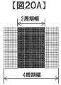
- FIG. 20A shows another example of the synchronization pattern.
- it is a pattern having a four-cycle width centered on a portion having a width corresponding to two cycles of the clock pattern 103 with respect to the major axis direction of the page header region 1002, and the minor axis direction of the page header region 1002 is Unlike the example shown in FIGS. 19A and 19B, the clock pattern unit 101 and the data pattern unit 102 are uniform without being distinguished.
- FIG. 20B shows an example in which the example of the synchronization pattern shown in FIG. 20A is inserted into the page header area 1002, and the data portion in the figure is a part where bit patterns representing information of “1” or “0” are arranged. is there.
- the synchronization unit is a part where the synchronization pattern shown in FIG. 20A is arranged.
- a uniform synchronization pattern is applied without distinguishing between the clock pattern unit 101 and the data pattern unit 102
- the synchronization pattern can be determined.
- the width of the synchronization pattern is exactly an integral multiple of the cycle of the clock pattern. By selecting this, it is possible to interpolate the clock pattern.
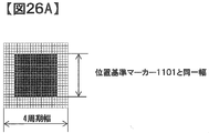
- FIG. 26A shows still another example of the synchronization pattern.
- the length is the same width as the position reference marker 1801, and is clearly longer than the 0.5 or 1 clock cycle length pattern that forms the data pattern and the clock pattern.
- This is an integer (4 in the figure) clock cycle width pattern that has a rectangular central part with an axial size (in the figure, 2 clock periods long) and is surrounded by pixels that differ in polarity from the central part.
- FIG. 26B shows an example in which the synchronization pattern shown in FIG. 26A is inserted into the page header area 1002, and the data portion in the figure is a part where bit patterns representing information of “1” or “0” are arranged.
- the synchronization unit is a part where the synchronization pattern shown in FIG. 26A is arranged.
- a synchronization pattern When such a synchronization pattern is applied, it is possible to discriminate the synchronization pattern by detecting the central part based on the polarity change positions in the short axis and long axis directions. Further, regarding the length of the page header region 1002 in the major axis direction, if the length of the data portion is sufficiently larger than the width of the synchronization portion, the clock pattern interrupted by the synchronization portion can be interpolated. Further, when the synchronization pattern shown in FIG.
- the marker center upper boundary line 1802, the marker center lower boundary line 1804, and the marker center center line 1803 for determining the position can be used.
- each page header area 1002 has a clock pattern 103 as shown in FIG.
- a header pattern provided with two data patterns (data pattern A 1704 and data pattern B 1705) is applied.
- a total of four data patterns existing in the two page header areas are defined as leader1, Header2, Header3, and Header4.
- the same information is stored in these four page header areas, and the data is quadrupled, but the arrangement order of the stored data is different in each area.
- the data pattern area of these four page header areas is further divided into four parts, and the data to be stored is also divided into Part A, B, C, D, and Part A in Headers 1 to 4 , B, C, and D are arranged as follows.
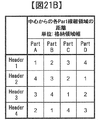
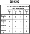
- An example satisfying this arrangement order is shown in FIGS. 21A and 22A.
- Part ABCD Header 1 in FIG. 21A
- Part ABCD Header 1 in FIG. 21A
- the arrangement order in the remaining three headers is Part DCABA (FIG. 21A, Header CD), Part CDA-B (Header 3 in FIG. 21A), Part B-A-D-C (Header 4 in FIG. 21A).
- the header is arranged in the order of Part ABCDD (Header 1 in FIG. 22A) from the center of the page data in the header
- the arrangement order in the remaining three headers is Part DCBA (Header 2 in FIG. 22A), Part C-A-D-B (Header 3 in FIG. 22A), and Part B-D-A-C (Header 4 in FIG. 22A).
- FIG. 21B shows the arrangement order from the center of Part A, B, C, D in each Header in the arrangement of FIG. 21A, and the arrangement order from the center in the four Headers is different for all Part. It is shown.
- FIG. 22B shows the arrangement order from the center of Part A, B, C, and D in each Header in the arrangement of FIG. 22A, and the arrangement order from the center in the four Headers for all Part. It is shown that they are different from each other. This means that there is no bias with respect to the arrangement of each Part, and there is a small risk that a specific Part will occur in the determination in all four Headers.
- each header is divided into four parts.
- the number of divisions is not necessarily limited to four.
- each header is part of Part A 'Part B'. The same effect can be obtained even if the two parts are divided and arranged so that the opposing Part is different with the clock pattern interposed therebetween.
- the number of headers to be arranged is not necessarily four.
- a page in which a data pattern 104 consisting of two regions of Part A ′ and Part B ′ in a row along the clock pattern 103 is provided.
- the same effect can be obtained by arranging the headers of header 1 and header 2 with the configuration of the header region 1002 and the center of the header pattern in the long side direction.
- the page header region 1002 may be provided with the data pattern 104 sandwiched between the clock patterns 103, and the two headers Header1 and Header2 may be arranged to face each other across the clock pattern 102. A similar effect can be obtained.
- Fig. 5 (a) shows an example of a page header generation flow.
- the generation of a page header includes a storage information encoding step 2701, a header data string generation step 2702, and a header patterning step 2703.
- a header storage information acquisition step 2704 for acquiring or generating information to be stored in the header such as information representing the pattern format of page data and information for identifying page data is obtained.
- a CRC code adding step 2705 for adding a CRC code used for error detection during reproduction to the information, and a step 2706 for performing error correction coding on the data after the CRC code addition are performed. Through these steps, error-corrected encoded information to be stored in the page data is generated.
- header data sequence generation step 2702 data sequences corresponding to each data pattern are recorded in a page header multiplexed and recorded from the encoded information obtained in storage information encoding step 2701 to ensure reliability. Is generated.
- the error correction encoded information generated in the payment information encoding step 2701 is divided into several partial data strings. For example, when generating the page header shown in FIG. 15, FIG. 16, FIG. 21, and FIG. 22, it is divided into four partial data strings of Part A, B, C, and D, and shown in FIG. If the indicated page header is used, it is divided into two partial data strings of Part A ′ and B ′.
- each header data string synthesizing step 2708 the partial data strings obtained in the storage information encoding step 2701 are appropriately rearranged to synthesize data strings corresponding to the respective data patterns.
- Header 1 in which partial data strings are arranged in the order of Part ABCD from the center of the page
- Partial data strings in the order of Part DCBA.
- Data sequence corresponding to Header 4 and Header 4 in which partial data sequences are arranged in the order of Header 3 and Part BDAC in which the partial data sequences are arranged in the order of Header 2 and Part C-A-D-B. Is synthesized.
- Header 1 in which partial data strings are arranged in the order of Part A′-B ′ from the center of the page
- Header 2 in which partial data strings are arranged in the order of Part B′-A ′.
- a data string corresponding to is synthesized.
- a two-dimensional header pattern to be displayed on the page data is generated based on the data string generated in the header data string generating step 2702.
- a two-dimensional pattern (for example, FIG. 1A or FIG. 1) consisting of a plurality of pixels determined corresponding to 1-bit information is applied to the data sequence generated in the header data sequence generation step 2702. 17A and 17B) are arranged, and a two-dimensional data pattern 104 and a clock pattern 103 arranged along this are generated.
- the two-dimensional pattern corresponding to this 1-bit information is selected so that the generated clock pattern 103 and data pattern satisfy the following conditions.
- each data pattern and clock pattern generated in the data pattern and clock pattern generation step 2709 is arranged in a predetermined pixel position in the page data.
- a position reference pattern and a synchronization pattern are added to the header pattern arranged in the page data arrangement step 2710. According to the above flow, a two-dimensional pattern of the page header can be generated. The generated two-dimensional pattern is recorded on the optical information recording medium 1.
- FIG. 5B shows an example of the reproduction flow of the page header generated as described above.
- a position reference pattern search step 2801 In the reproduction of page data, a position reference pattern search step 2801, a data pattern and clock pattern short axis direction determination position determination step 2802, a data pattern long axis direction determination position determination step 2803, a header data string restoration step 2804, and a stored data acquisition step 2805.
- a position reference pattern is searched from the entire two-dimensional page data detected by the photodetector 325. For simplicity, at least one of the distances between the polarity change points in the major axis direction and the minor axis direction is recorded around the pixel position of the photodetector that is expected to detect the position reference pattern.
- a position reference pattern can be searched for by searching for a pattern that is about the number of pixels in the center of the reference pattern. More precisely, an expected value pattern of the position reference pattern image detected by the photodetector 325 is obtained in advance, and the position reference pattern is detected around the pixel position of the photodetector that is expected to detect the position reference pattern.
- the position reference pattern can be determined by acquiring a plurality of two-dimensional patterns having a size expected to be imaged and selecting the one having the maximum covariance value or total correlation value between these and the expected value pattern.
- the data pattern and clock pattern short axis direction determination position determination step 2802 the short axis direction determination position of each of the data pattern and the clock pattern is obtained based on the determined position reference pattern.
- the position reference pattern short axis direction polarity reversal detection step 2806 the boundary position in the short axis direction of the header between the central portion and the peripheral portion of the position reference pattern is obtained.
- step 2807 of calculating the marker center upper boundary line and the marker center lower boundary line a straight line connecting the boundary positions in the minor axis direction of the header between the center part and the peripheral part of the adjacent position reference pattern is obtained. Therefore, the short axis direction discrimination position of each of the data pattern and the clock pattern is determined.
- the determination position of the data pattern in the long axis direction is obtained, and the data pattern and the clock pattern in the short axis direction determination position determination step 2802 are combined with the data in the short axis direction.
- the position of the pixel used for pattern discrimination is determined.
- a clock pattern detection signal acquisition step 2808 pixel information of a pixel area where the clock pattern exists is acquired.
- a clock pattern center level detection step 2809 the center level of the clock pattern region is detected from the pixel information acquired in the clock pattern detection signal acquisition step 2808.
- the pixel information and the clock pattern center level detection step 2809 arranged in the major axis direction at the position in the minor axis direction of the clock pattern discrimination determined in the data pattern and clock pattern minor axis direction discrimination position determination step 2802. From the obtained center level, the clock pattern polarity change position (zero cross point) is obtained. In the polarity inversion period / number determination 2811, the interval and the number of the polarity change positions of the obtained clock pattern are obtained.
- the correction processing step 2811 if there are locations where the interval is smaller than the assumed range and there are a large number, It is considered that a non-original clock pattern is detected and excluded, and conversely, if there are places where the interval is larger than the expected range and the number is small, there are places that were not detected due to defects etc. It is assumed that interpolation is performed based on the surrounding polarity change position.
- the data pattern discrimination position determination step 2813 the major axis direction for discriminating the data pattern is obtained based on the polarity change position determined through the correction processing step 2811, and in the data pattern and clock pattern minor axis direction discrimination position determination step 2802. A pixel for determining the data pattern is determined in accordance with the obtained position in the minor axis direction.
- the data pattern and the clock pattern are stored in the header from the data pattern based on the pixel information of the position obtained through the short axis direction determination position determination step 2802 and the data pattern long axis direction determination position determination step 2803. Determine the discriminant value of the data string.
- the data pattern amplitude determination step 2814 the recorded pattern is based on the amplitude level of the pixel information at the position obtained through the data pattern and clock pattern short axis direction determination position determination step 2802 and the data pattern long axis direction determination position determination step 2803. Discriminate between on-pixel and off-pixel. Since the data pattern and the clock pattern are close to each other, the respective center levels can be regarded as equivalent.
- the amplitude level of the pixel information is applied by using the center level obtained in the clock pattern center level detection step 2809 as a reference. Compare with.
- the data decoding step 2815 the data string stored in the data pattern is decoded based on the result of the data pattern amplitude determining step 2814. .
- the data string determined in the data decoding step 2815 is divided by the position and number determined at the time of recording to obtain a partial data string.
- the partial data sequence obtained in the data division step 2816 is changed in order so as to restore the arrangement conversion processing in each header data sequence synthesis step 2708 at the time of recording, and the data stored in the header Get the discriminant value for a column.
- the partial data strings subjected to the layout conversion process in the layout order restoration step 2817 do not necessarily have the same data pattern, and partial data strings determined from different data patterns may be combined.
- the data patterns of Headers 1, 2, 3, and 4 storing four partial data strings of Part A, B, C, and D are arranged.
- a partial data sequence obtained from Part A of Header 1 a partial data sequence obtained from Part B of Header 2, a partial data sequence obtained from Part C of Header 3, and a partial data sequence obtained from Part D of Header 4 You may combine.
- correct storage information is acquired based on the discriminant value of each data string obtained in the header data string restoration step 2804.
- the error correction step 2818 performs error correction processing in a format corresponding to the error correction encoding step 2706 performed at the time of recording on the discriminant value of each data string obtained in the header data string restoration step 2804.
- a wrinkle error detection process corresponding to the format of the CRC code addition step 2705 at the time of recording is performed on the data string obtained as a result of the error correction step 2818.
- correct data selection step 2820 a data string determined to be correct is selected from the discriminant value of each data string obtained in header data string restoration step 2804, and obtained through error correction step 2818 and error detection step 2819.
- step 2817 for dividing each stored information the data string determined to be correct is divided for each information stored at the time of recording (for example, information indicating a pattern format or information for identifying page data).
- the divided information is transmitted to the controller 89 via a memory element or a register.
- the data stored in the page header can be reproduced by the flow shown in FIG.
- a page header pattern is generated by the above-described page header generation flow of FIG. 5A and this pattern is reproduced by the reproduction flow of FIG. Identification can be performed easily and accurately.
- the present invention is not limited to this, and the present invention can also be applied to a pattern of three or more values. I can do it.
- the present invention can be applied not only to the angle multiplexing method but also to other methods such as a shift multiplexing method.
- this invention is not limited to the above-mentioned Example, Various modifications are included.
- the above-described embodiments have been described in detail for easy understanding of the present invention, and are not necessarily limited to those having all the configurations described.
- a part of the configuration of one embodiment can be replaced with the configuration of another embodiment, and the configuration of another embodiment can be added to the configuration of one embodiment.
- each of the above-described configurations, functions, processing units, processing means, and the like may be realized by hardware by designing a part or all of them by, for example, an integration means.
- Each of the above-described configurations, functions, and the like may be realized by software by interpreting and executing a program that realizes each function by the processor.
- Information such as programs, tables, and files that realize each function can be stored in a memory, a hard disk, a recording device such as an SSD (Solid State Drive), or a recording medium such as an IC card, an SD card, or a DVD.
- control lines and information lines indicate what is considered necessary for the explanation, and not all the control lines and information lines on the product are necessarily shown. Actually, it may be considered that almost all the components are connected to each other.
- SYMBOLS 1 Optical information recording medium, 10 ... Optical information recording / reproducing apparatus, 11 ... Pickup, 12 ... Reference light optical system for reproduction, 13 ... Disc Cure optical system, 14 ... Optical system for detecting the disk rotation angle, 101 ... Clock pattern part 102: Data pattern part 103 ... clock pattern 104 ... Data pattern 105 ... Clock pattern detection signal 106 ... Data pattern detection signal 81 ... access control means, 82... Light source driving means, 83... Servo signal generating means, 84 ... servo control means, 85 ... signal processing means, 86 ... signal generation means, 87 ... shutter control means, 88 ... disk rotation motor control means, 89 ...
- Controller 90 ... Input / output control means, 91 ... External control device, 301 ... light source, 303 ... shutter, 306 ... signal light, 307 ... reference light, 308 ... Beam expander, 309 ... Phase mask 310 ... relay lens, 311 ... PBS prism, 312 ... Spatial light modulator, 313 ... Relay lens, 314 ... Spatial filter, 315 ... objective lens, 316 ... polarization direction conversion element, 320 ... actuator, 321 ... lens, 322 ... lens, 323 ... actuator, 324 ... Mirror, 325 ... Photodetector 501 ... Light source, 502 ... Collimating lens, 503 ... Shutter, 504 ...
Landscapes
- Optical Recording Or Reproduction (AREA)
Abstract
ホログラフィックメモリの再生処理において、ユーザデータの判別に先行して行う、検出したページデータが予め定めた目標データを含むページであることを確認する処理やデータ形式を識別する処理を容易かつ正確に行えるようにする。 ページデータの識別情報やデータ形式を識別するための情報を格納したページヘッダをページデータのパターン内に設ける。ページヘッダには一次元的なパターンをなすデータパタンに沿って、一定周期でオンピクセルとオフピクセルが繰り返されるクロックパタンを配置する。
Description
本発明は、ホログラフィを用いて情報を記録するための記録媒体と、この種の記録媒体に情報を再生する方法に関する。
現在100GB程度の記録容量を有する光ディスクが商品化され、今後はハードディスクドライブと同程度の大容量化が望まれるが、このような高密度の実現には、光源の短波長化と対物レンズの高NA化を主とした従来の高密度化技術とは異なる新しい方式が必要である。
このような背景の下、次世代の光ストレージ技術に関する研究が行われる中で、ホログラフィを利用してデジタル情報を記録するホログラム記録技術が注目を集めている。
ホログラム記録技術とは、空間光変調器により2次元的に変調されたページデータの情報を有する信号光を、記録媒体の内部で信号光と同一の波長を有する参照光と重ね合わせ、その時に生じる干渉縞パターンによって記録媒体内に屈折率変調を生じさせることで情報を記録媒体に記録する技術である。
情報の再生時には、記録時に用いた参照光を記録媒体に照射すると、記録媒体中に記録されているホログラムが回折格子のように作用して回折光を生じる。この回折光が記録した信号光と位相情報を含めて同一の光として再生される。
再生された信号光は、CMOSやCCDなどのイメージセンサーを用いて2次元的に高速に検出される。このようにホログラム記録技術は、1つのホログラムによって2次元的な情報を同時に光記録媒体に記録し、さらにこの情報を再生することを可能とするものであり、そして、記録媒体のある場所に複数のページデータを重ね書きすることができるため、大容量かつ高速な情報の記録再生を果たすことができる。
ホログラム記録技術として、例えば特開2004-272268号公報(特許文献1)がある。本公報には、「ホログラムの隣接するスタック間で部分的空間的重なり合いによってホログラムが空間的に多重化される、多重化方法および装置が開示される。各々のスタックは、例えば角度、波長、位相符号、ペリストロピック、またはフラクタル多重化等の別の多重化技術の完全な利点をさらに取り得る。ホログラムを書き込む信号光のビームウエストに等しい量が、ホログラムの個々のスタックを分離する。再現時に、あるホログラムとそのホログラムに隣接するホログラムとは、全て同時に読み出される。再現されたデータのビームウエストにフィルタが配置されることにより、読み出された隣接するホログラムは、カメラ面まで伝達されない。もしくは、これらの所望ではない再現は、制限された角度パスバンドを有する光学系においては、中間面の角度フィルタによってフィルタリングされ得る。」と記載されている。
またホログラム再生技術として、例えば特表2008-536158号公報(特許文献2)がある。本公報には、「各データページ全体にわたって、所定の予備のブロックを割り当てることであって、各予備のブロックは既知の画素パターンを含む、ことと、データページの領域と所定の予備のブロックとの間の最良のマッチングを計算することによって、データページの位置誤差を決定することと、検出器においてデータ画素を対応するデータページの位置誤差に従って補正することとを包含する」処理を行うことによって、二次元ページデータを判別可能とする処理が記載されている。
また、特開2006-259519号公報(特許文献3)には、ホログラム記録において、ヘッダ情報を強調記録する技術が開示されている。
ところで、ホログラム記録媒体から情報を再生するときには、イメージセンサーを用いて取得したページデータ像からユーザデータを復号する前に、検出したページデータが予め定めた目標データを含むページであることを確認する必要がある。また、同一媒体内に複数のデータ形式で記録されたページデータが混在して記録されている場合には、同様にユーザデータを復号する前にデータ形式を識別する必要がある。
特許文献3には、ヘッダ情報を強調記録する技術が開示されている。しかし、この技術を用いて記録すると、再生時においてヘッダ情報を記録した部位では他の部位よりも強度の大きい光が検出されるため、他の部位における検出光量が最適となるようにしたときに、ヘッダ情報の部位はイメージセンサの検出レンジを超過し、適正な処理を行えないおそれがある。逆に、ヘッダ情報の部位において適正な検出光量となるようにすると、他の部位の検出光量が過小となり、正しく検出できないおそれがある。
これらのページデータの確認やデータ形式の判別に用いるような情報は、正確かつ短い処理時間で行うために、ユーザデータよりも簡便かつ正確な判別が可能な形式で記録されることが望ましい。
そこで本発明では、ページデータの判別やデータ形式の識別を簡便かつ正確に行うこと可能とする光情報記録媒体、光情報記録方法および光情報再生方法を提供することを目的とした。
上記課題は、例えば請求の範囲に記載の発明により解決される。
本発明によれば、ページデータの判別やデータ形式の識別を簡便かつ正確に行うことが可能となる。
以下、本発明の実施例について図面を用いて説明する。
本発明の実施形態を添付図面に従って説明する。図2はホログラフィを利用してデジタル情報を記録および/または再生する光情報記録媒体の記録再生装置を示すブロック図である。
光情報記録再生装置10は、入出力制御手段90を介して外部制御装置91と接続されている。記録する場合には、光情報記録再生装置10は外部制御装置91から記録する情報信号を入出力制御手段90により受信する。再生する場合には、光情報記録再生装置10は再生した情報信号を入出力制御手段90により外部制御装置91に送信する。
光情報記録再生装置10は、ピックアップ11、再生用参照光光学系12、キュア光学系13、ディスク回転角度検出用光学系14、及び回転モータ50を備えており、光情報記録媒体1は回転モータ50によって回転可能な構成となっている。
ピックアップ11は、参照光と信号光を光情報記録媒体1に照射してホログラフィを利用してデジタル情報を記録媒体に記録する役割を果たす。この際、記録する情報信号はコントローラ89によって信号生成手段86を介してピックアップ11内の空間光変調器に送られ、信号光は空間光変調器によって変調される。
光情報記録媒体1に記録した情報を再生する場合は、ピックアップ11から出射された参照光を記録時とは逆の向きに光情報記録媒体に入射させる光波を再生用参照光光学系12にて生成する。再生用参照光によって再生される再生光をピックアップ11内の後述する光検出器によって検出し、信号処理手段85によって信号を再生する。
光情報記録媒体1に照射する参照光と信号光の照射時間は、ピックアップ11内のシャッタの開閉時間をコントローラ89によってシャッタ制御手段87を介して制御することで調整できる。
キュア光学系13は、光情報記録媒体1のプリキュアおよびポストキュアに用いる光ビームを生成する役割を果たす。プリキュアとは、光情報記録媒体1内の所望の位置に情報を記録する際、所望位置に参照光と信号光を照射する前に予め所定の光ビームを照射する前工程である。ポストキュアとは、光情報記録媒体1内の所望の位置に情報を記録した後、該所望の位置に追記不可能とするために所定の光ビームを照射する後工程である。
ディスク回転角度検出用光学系14は、光情報記録媒体1の回転角度を検出するために用いられる。光情報記録媒体1を所定の回転角度に調整する場合は、ディスク回転角度検出用光学系14によって回転角度に応じた信号を検出し、検出された信号を用いてコントローラ89によってディスク回転モータ制御手段88を介して光情報記録媒体1の回転角度を制御する事が出来る。
光源駆動手段82からは所定の光源駆動電流がピックアップ11、キュア光学系13、ディスク回転角度検出用光学系14内の光源に供給され、各々の光源からは所定の光量で光ビームを発光することができる。
また、ピックアップ11、そして、ディスクキュア光学系13は、光情報記録媒体1の半径方向に位置をスライドできる機構が設けられており、アクセス制御手段81を介して位置制御がおこなわれる。
ところで、ホログラフィの角度多重の原理を利用した記録技術は、参照光角度のずれに対する許容誤差が極めて小さくなる傾向がある。
従って、ピックアップ11内に、参照光角度のずれ量を検出する機構を設けて、サーボ信号生成手段83にてサーボ制御用の信号を生成し、サーボ制御手段84を介して該ずれ量を補正するためのサーボ機構を光情報記録再生装置10内に備えることが必要となる。
また、ピックアップ11、キュア光学系13、ディスク回転角度検出用光学系14は、いくつかの光学系構成または全ての光学系構成をひとつに纏めて簡素化しても構わない。
図3は、光情報記録再生装置10におけるピックアップ11の基本的な光学系構成の一例における記録原理を示したものである。光源301を出射した光ビームはコリメートレンズ302を透過し、シャッタ303に入射する。シャッタ303が開いている時は、光ビームはシャッタ303を通過した後、例えば2分の1波長板などで構成される光学素子304によってp偏光とs偏光の光量比が所望の比になるようになど偏光方向が制御された後、PBS(Polarization Beam Splitter)プリズム305に入射する。
PBSプリズム305を透過した光ビームは、信号光306として働き、ビームエキスパンダ308によって光ビーム径が拡大された後、位相マスク309、リレーレンズ310、PBSプリズム311を透過して空間光変調器312に入射する。
空間光変調器312によって情報が付加された信号光は、PBSプリズム311を反射し、リレーレンズ313ならびに空間フィルタ314を伝播する。その後、信号光は対物レンズ315によって光情報記録媒体1に集光する。
一方、PBSプリズム305を反射した光ビームは参照光307として働き、偏光方向変換素子316によって記録時または再生時に応じて所定の偏光方向に設定された後、ミラー317ならびにミラー318を経由してガルバノミラー319に入射する。ガルバノミラー319はアクチュエータ320によって角度を調整可能のため、レンズ321とレンズ322を通過した後に光情報記録媒体1に入射する参照光の入射角度を、所望の角度に設定することができる。なお、参照光の入射角度を設定するために、ガルバノミラーに代えて、参照光の波面を変換する素子を用いても構わない。
このように信号光と参照光とを光情報記録媒体1において、互いに重ね合うように入射させることで、記録媒体内には干渉縞パターンが形成され、このパターンを記録媒体に書き込むことで情報を記録する。また、ガルバノミラー319によって光情報記録媒体1に入射する参照光の入射角度を変化させることができるため、角度多重による記録が可能である。
以降、同じ領域に参照光角度を変えて記録されたホログラムにおいて、1つ1つの参照光角度に対応したホログラムをページと呼び、同領域に角度多重されたページの集合をブックと呼ぶことにする。
図4は、光情報記録再生装置10におけるピックアップ11の基本的な光学系構成の一例における再生原理を示したものである。記録した情報を再生する場合は、前述したように参照光を光情報記録媒体1に入射し、光情報記録媒体1を透過した光ビームを、アクチュエータ323によって角度調整可能なガルバノミラー324にて反射させることで、その再生用参照光を生成する。
この再生用参照光によって再生された再生光は、対物レンズ315、リレーレンズ313ならびに空間フィルタ314を伝播する。その後、再生光はPBSプリズム311を透過して光検出器325に入射し、記録した信号を再生することができる。光検出器325としては例えばCMOSイメージセンサーやCCDイメージセンサーなどの撮像素子を用いることができるが、ページデータを再生可能であれば、どのような素子であっても構わない。
図6は、光情報記録再生装置10における記録、再生の動作フローを示したものである。ここでは、特にホログラフィを利用した記録再生に関するフローを説明する。
図6(a)は、光情報記録再生装置10に光情報記録媒体1を挿入した後、記録または再生の準備が完了するまでの動作フローを示し、図6(b)は準備完了状態から光情報記録媒体1に情報を記録するまでの動作フロー、図6(c)は準備完了状態から光情報記録媒体1に記録した情報を再生するまでの動作フローを示したものである。
図6(a)に示すように媒体を挿入すると(601)、光情報記録再生装置10は、例えば挿入された媒体がホログラフィを利用してデジタル情報を記録または再生する媒体であるかどうかディスク判別を行う(602)。
ディスク判別の結果、ホログラフィを利用してデジタル情報を記録または再生する光情報記録媒体であると判断されると、光情報記録再生装置10は光情報記録媒体に設けられたコントロールデータを読み出し(603)、例えば光情報記録媒体に関する情報や、例えば記録や再生時における各種設定条件に関する情報を取得する。
コントロールデータの読み出し後は、コントロールデータに応じた各種調整やピックアップ11に関わる学習処理(604)を行い、光情報記録再生装置10は、記録または再生の準備が完了する(605)。
準備完了状態から情報を記録するまでの動作フローは図6(b)に示すように、まず記録するデータを受信して(611)、該データに応じた情報をピックアップ11内の空間光変調器に送る。
その後、光情報記録媒体に高品質の情報を記録できるように、必要に応じて例えば光源301のパワー最適化やシャッタ303による露光時間の最適化等の各種記録用学習処理を事前に行う(612)。
その後、シーク動作(613)ではアクセス制御手段81を制御して、ピックアップ11ならびにキュア光学系13の位置を光情報記録媒体の所定の位置に位置づけする。光情報記録媒体1がアドレス情報を持つ場合には、アドレス情報を再生し、目的の位置に位置づけされているか確認し、目的の位置に配置されていなければ、所定の位置とのずれ量を算出し、再度位置づけする動作を繰り返す。
その後、キュア光学系13から出射する光ビームを用いて所定の領域をプリキュアし(614)、メインデータ生成(615)とページヘッダ付加(616)を含むページデータ生成処理(617)を行い、ピックアップ11から出射する参照光と信号光を用いてデータを記録する(618)。データを記録した後は、キュア光学系13から出射する光ビームを用いてポストキュアを行う(619)。必要に応じてデータをベリファイしても構わない。メインデータはページデータのうちの大半を占める部位であり、主としてユーザデータが格納される。ユーザデータ以外に、特定のページデータにおいて、外部制御装置91が扱う論理アドレスと光情報記録媒体1における各ページデータの位置との対応を表すテーブルや、欠陥によって再生困難になったページデータの交替処理における、交替前と交替先とのページデータの位置の対応を表す交替位置リストを格納するようにしてもよい。また、ページヘッダとはページデータに記録されたデータの種別やデータ形式、多重記録されたページを識別のためのアドレスなどの情報を格納するためにページデータ上に設けた領域であり、メインデータとはページデータ上の記録するための領域と分けて設ける。
準備完了状態から記録された情報を再生するまでの動作フローは図6(c)に示すように、まずシーク動作(621)で、アクセス制御手段81を制御して、ピックアップ11ならびに再生用参照光光学系12の位置を光情報記録媒体の所定の位置に位置づけする。光情報記録媒体1がアドレス情報を持つ場合には、アドレス情報を再生し、目的の位置に位置づけされているか確認し、目的の位置に配置されていなければ、所定の位置とのずれ量を算出し、再度位置づけする動作を繰り返す。
続いて、ピックアップ11から参照光を出射し、光情報記録媒体に記録された情報を読み出し、ページデータを取得し(622)、ページデータ内のページヘッダ部の判別(623)の後に再生データを検出(624)して送信する(625)。ページヘッダ部の判別(623)の結果として目標とするページデータと識別されない場合においては、目標とは異なるページデータを検出しているおそれがあるので、再生データの送信(625)は行わずに中止するか、(621)(622)の処理から再度実行しなおす。
図9は、記録、再生時のデータ処理フローを示したものであり、図9(a)は、入出力制御手段90において記録データ受信処理611後、空間光変調器312上の2次元データに変換するまでの信号生成手段86での記録データ処理フローを示しており、図9(b)は光検出器325で2次元データを検出後、入出力制御手段90における再生データ送信処理624までの信号処理手段85での再生データ処理フローを示している。
図9(a)を用いて記録時のデータ処理について説明する。901から906までの処理は、図6(b)の処理におけるメインデータ生成(615)の内部の処理に対応する。信号生成手段81がユーザデータを受信(901)すると、複数のデータ列に分割、再生時エラー検出が行えるように各データ列をCRC化(902)し、オンピクセル数とオフピクセル数をほぼ等しくし、同一パターンの繰り返しを防ぐことを目的にデータ列に擬似乱数データ列を加えるスクランブル(903)を施した後、再生時にエラー訂正が行えるようにリード・ソロモン符号等の誤り訂正符号化(904)を行う。次に誤り訂正符号化されたデータ列を予め定めた規則に従って配置して、2次元データ(905)を構成する。なお、905の処理においてランレングス制限変調などの変調処理を加えてもよい。このように構成した2次元データに対して再生時の画像位置検出や画像歪補正での基準となるマーカーを付加(906)し、ページヘッダを付加(616)の上で空間光変調器312にデータを転送(907)する。
次に図9(b)を用いて再生時のデータ処理フローについて説明する。912から919までの処理は、図6(c)の処理におけるデータ再生(624)の内部の処理に対応する。光検出器325で検出された画像データが信号処理手段85に転送(911)されるとともに、検出された画像データから、ページヘッダを判別(623)し、ページヘッダに格納されたデータを取得する、次に、この画像データに含まれるマーカーを基準に画像位置を検出(912)し、画像の傾き・倍率・ディストーションなどの歪みを補正(913)した後、2値化処理(914)を行い、マーカーを除去(915)することで1ページ分の2次元データを取得(916)する。このようにして得られた2次元データを複数のデータ列に変換した後、誤り訂正処理(917)を行い、パリティデータ列を取り除く。次にスクランブル解除処理(918)を施し、CRCによる誤り検出処理(919)を行ってCRCパリティを削除した後にユーザデータを入出力制御手段90経由で送信(920)する。なお、マーカーによる画像位置検出(912)が、ページヘッダの判別(623)よりも容易に行えることが期待できる場合は、これらの処理の順序を入れ替えて、マーカーによる画像位置検出結果を用いてページヘッダの探索を行ってもよい。
図7は、光情報記録再生装置10の信号生成手段86のブロック図である。
出力制御手段90にユーザデータの入力が開始されると、入出力制御手段90はコントローラ89にユーザデータの入力が開始されたことを通知する。コントローラ89は本通知を受け、信号生成手段86に入出力制御手段90から入力される1ページ分のデータを記録処理するよう命ずるとともに、ページヘッダに格納する情報をヘッダパタン生成手段710に与える。コントローラ89からの処理命令は制御用ライン708を経由し、信号生成手段86内サブコントローラ701に通知される。この通知を受け、サブコントローラ701は各信号処理手段を並列に動作させるよう制御用ライン708を介して各信号処理手段の制御を行う。
先ずメモリ制御手段703に、データライン709を介して入出力制御手段90から入力されるユーザデータをメモリ702に格納するよう制御する。メモリ702に格納したユーザデータが、ある一定量に達すると、CRC演算手段704でユーザデータをCRC化する制御を行う。次にCRC化したデータに、スクランブル手段705で擬似乱数データ列を加えるスクランブル化を施し、誤り訂正符号化手段706でパリティデータ列を加える誤り訂正符号化する制御を行い、さらにマーカー付加手段 710によって再生時に基準となるマーカーを付加してページデータのうちのメインデータの部分の記録パターンを生成し、メモリ702に格納する。一方で、ヘッダパタン生成手段711では、コントローラ89から入力されたページヘッダに格納する情報に基づいてページヘッダの記録パターンを生成し、メモリ702に格納する。
最後にピックアップインターフェース手段707にメモリ702からメインデータの記録パターンとページヘッダの記録パターンを空間光変調器312上の2次元データの並び順で読み出させ、ピックアップ11内の空間光変調器312に2次元データを転送する。
図8は、光情報記録再生装置10の信号処理手段85のブロック図である。
コントローラ89はピックアップ11内の光検出器325が画像データを検出すると、信号処理手段85にピックアップ11から入力される1ページ分のデータを再生処理するよう命ずる。コントローラ89からの処理命令は制御用ライン811を経由し、信号処理手段85内サブコントローラ801に通知される。本通知を受け、サブコントローラ801は各信号処理手段を並列に動作させるよう制御用ライン811を介して各信号処理手段の制御を行う。先ず、メモリ制御手段803に、データライン812を介して、ピックアップ11からピックアップインターフェース手段810を経由して入力される画像データをメモリ802に格納するよう制御する。
メモリ802に格納されたデータがある一定量に達すると、ヘッダパタン復号手段813によってページヘッダに格納されたデータを復号し、検出されたページデータの識別情報が再生の目標とするページデータであると判定したのちに、続いて画像位置検出手段809でメモリ802に格納された画像データ内からマーカーを検出して有効データ範囲を抽出する制御を行う。次に検出されたマーカーを用いて画像歪み補正手段808で、画像の傾き・倍率・ディストーションなどの歪み補正を行い、画像データを期待される2次元データのサイズに変換する制御する。サイズ変換された2次元データを構成する複数ビットの各ビットデータを、2値化手段807において“0”、“1”判定する2値化し、メモリ802上に再生データの出力の並びでデータを格納する制御を行う。次に誤り訂正手段806で各データ列に含まれる誤りを訂正し、スクランブル解除手段805で擬似乱数データ列を加えるスクランブルを解除した後、CRC演算手段804でメモリ802上のユーザデータ内に誤りが含まれない確認を行う。その後、入出力制御手段90にメモリ802からユーザデータを転送する。
ここで、ページヘッダの記録パターンと記録再生方法ならびに記録再生装置について詳細に説明する。
図10Aは、空間光変調器312の画素面における信号光およびページデータの位置と、ページデータ内におけるページヘッダ領域の位置を示している。1001はメインデータ領域、1002はページヘッダ領域、1003は空間光変調器の画素、1004は信号光光軸位置である。
空間光変調器の画素1003は、図10Aの拡大図部に示すように直交する2方向に沿ってマトリクス状に配置されており、ここではそれぞれの方向をX方向とY方向と定義している。また、空間光変調器の画素1003のこれらの方向に対する画素のサイズをΔX、ΔYと表記している。
信号光光軸位置1004は、空間光変調器312の画素面上において、リレーレンズ313、空間フィルタ314、対物レンズ315を経て光情報記録媒体に向かう信号光314の光軸が位置する点である。
側面図はX方向とY方向に対する信号光306とリレーレンズ313、空間フィルタ314の断面図を表しており、空間フィルタ314の開口サイズをそれぞれXspf 、Yspfと表記している。また、リレーレンズ313と図3で示した対物レンズ315の有効径範囲内の領域を通過する信号光のみが媒体へのホログラム記録に寄与するので、ここではこれらの有効径のうちの小さい方として信号光306の幅を扱う。
メインデータ領域1001は、ページデータにおいて主としてユーザデータが記録される領域であり、空間光変調器312の画素面上において、信号光光軸位置1004を中心とし、リレーレンズ313と図3で示した対物レンズ315の有効径のうちのいずれか小さいほうと概ね同等の直径を有する円としている。このような円状の領域とすることによって、リレーレンズ313と対物レンズ315の有効径の領域を無駄なく活用できるため、単一のページデータ内に格納可能な最大のデータサイズを得ることができる。なお、データサイズの損失を許容する場合においては、必ずしも円形でなくともよい。
ページヘッダ領域1002は、ページデータにおいて記録されたデータの種別やデータ形式、多重記録されたページを識別のためのアドレスなどの情報を格納するページヘッダを記録するための領域であり、信号光光軸位置1004を通るX方向またはY方向の直線上に配置し、これらの直線の方向を長辺とする長方形状の領域とする。
図10AはX方向とY方向の両方向にページヘッダ領域1002を設けた例である。
図10BはX方向のみに設けた例である。図10CはY方向のみに設けた例である。
また、図10DはX方向のみに2つのページヘッダ領域1002を設けた例であり、このように分断された複数のページヘッダ領域1002を設けてもよい。
このような位置・向きのページヘッダ領域1002を設けることによって、たとえばページデータの周辺部に集中して設けた場合と比較して光学部品の収差の影響を受けにくく、再生時に検出像の歪が小さいページヘッダ像を取得可能とする効果が得られる。
なお、本実施例におけるページヘッダは、後述のようにページヘッダ領域1002の長辺方向に一次元的に配置したビットパタンとして記録される。一方で再生時に検出されるページデータ像の空間周波数の帯域幅は空間フィルタ314の開口サイズに比例するので、、空間光変調器312のピクセルサイズと空間フィルタ314の開口サイズの積が小さいほど、空間サンプリング周波数(空間光変調器312のピクセル間隔の逆数)に対する空間周波数帯域の比が小さくなり、ピクセル間の符号間干渉量は増大する。このため、X方向における空間光変調器312のピクセルサイズと空間フィルタ314の開口サイズの積とY方向における積の値が同等の場合は、図10Aのように両方向にページヘッダ領域1002を設けるとよく、X方向とY方向とで大きく異なる場合は、この積の値の小さい一方向のみに図10B、図10C、図11D等のように、ページヘッダ領域1002を設けるとよい。
このことは、たとえばページデータのいずれか一方の方向に沿ってオンピクセルおよびオフピクセルの少なくとも一方の最小連続長を制限する変調を行って、この方向の空間周波数帯域幅を低減させるとともに、この方向に対して他方の方向よりも開口サイズを小型化した空間フィルタ314を適用する場合にあてはまる。このような技術については、例えば特開2010-003358に開示されている。例えば、X方向のオンピクセルおよびオフピクセルの最小連続長を制限して、X方向の空間周波数を低減させるとともに、X方向の空間フィルタ314の開口サイズをY方向よりも短くした場合、Y方向のみに図10B等のように、ページヘッダ領域1002を設けると好ましい。X方向とY方向が逆であれば、X方向のみに、ページヘッダ領域1002を設けるとよい。開口サイズが長い方向は、ページヘッダ領域1002のデータを読み易くなる一方、開口サイズが短い方向については、読みにくくなるため、このように構成することで、ページヘッダ領域を正確に再生することが出来るとともに、メインデータ領域を多く確保することが出来る。
次に、ページヘッダ領域1002に設けるパターンについて説明する。図1はページヘッダ領域1002のパターンの一例を表す。
図1(a)は格納するデータの各ビットの情報を表すビットパタンの例である。101はクロックパタン部、102はデータパタン部である。また、図中の升目は空間光変調器312の画素を表す。各々の画素はオン・オフの2極性に光を変調する。白く示した画素はオンピクセルであり、黒く示した画素はオフピクセルである。
各ビットを表すビットパタンはクロックパタン部101とデータパタン部102を有し、それぞれはページヘッダ領域1002の短辺方向で近接している。“1”を表すビットパタンと“0”を表すビットパタンは、データパタン部102で区別され、クロックパタン部101は共通である。データパタン部をページヘッダ領域1002の長辺方向に二等分し、それぞれの領域のピクセルに対して互いに異なる極性を与えることで、記録するビット情報によらず一定の輝度レベルを保持するようにしている。
また、クロックパタン部101は、ページヘッダ領域1002の長辺方向に対して、両端1/4ずつの2領域(図1(a)中の2ピクセルずつに相当)と中央部(図1(a)中の4ピクセルに相当)の3領域からなり、中央部と周辺部が異なる極性となるようにしている。
図1(b)は,図1(a)で示したビットパタンを用いて、複数ビットのデータ列を表した一例である。103はクロックパタン、104はデータパタンである。
クロックパタン103は、ビットパタンの幅と同一の周期(図1(a), 図1(b)中の8ピクセルに相当)を有し、オンピクセル部とオフピクセル部の幅が等しい(図1(b)中の8ピクセルに相当)パターンをなす。
データパタン104は、ビットパタンと同一の幅(図1(a), 図1(b)中の8ピクセルに相当)またはその1/2の幅のいずれかのオンピクセル領域およびオフピクセル領域から構成される。また、ページヘッダ領域1002の長辺方向に対して、データパタン104の極性変化点はクロックパタン103の連続する極性変化点間の中央に位置する。
図1(c)は図1(b)に示したクロックパタン103とデータパタン104から得られる信号光の強度分布を、ページヘッダ領域1002の長辺方向に沿った直線上の位置を横軸として示した概略図である。ここでは、オンピクセルから得られる信号強度の方がオフピクセルから得られる信号強度よりも大きいものとして図示している。
105はクロックパタン検出信号であり、106はデータパタン検出信号である。縦軸は信号強度を表しており、信号の中心レベルを横軸との交点として図示している。各々の検出信号のプロット線と横軸との交点は、図1(b)における極性変化点に対応する。なお、横軸とのプロット線との交点を、以下ではゼロクロス点と表記する。
図1(b)においてデータパタン104の極性変化点がクロックパタン103の連続する極性変化点間の中央に位置することと対応して、データパタン検出信号106のゼロクロス点も等間隔に位置するクロックパタン検出信号105のゼロクロス点間の中央に位置する。
このことから、クロックパタン検出信号105からクロックパタンのゼロクロス位置を判別し、得られたゼロクロス位置におけるデータパタン検出信号106の信号強度を続いて検出して中心レベルと比較することによって、データパタンの判別を容易かつ正確に行える効果を得ることが期待できる。なお、中心レベルは、クロックパタン検出信号105に対しての繰り返し空間周波数をカットオフするローパスフィルタを用いて得ることができ、さらにはこのようにして得られたクロックパタン検出信号の中心レベルを用いて隣接するデータパタン検出信号106のパターン判別に用いることができる。また、クロックパタン検出信号のゼロクロス位置間の中央の信号レベルから、クロックパタン検出信号のピークレベルとボトムレベルを検出できる。これらを用いてデータパタン検出信号106や近傍のメインデータ領域の検出信号の振幅レベルの補正を行うことによって、データ検出の精度を改善する効果が得られる。また、クロックパタンは周期性を有することから、欠落箇所が生じた場合に、周囲の位置関係から補間することが可能である。
なお、図1(a)と図1(b)において、図中の上側にクロックパタン部101とクロックパタン103、下側にデータパタン部102、データパタン104を配置する例を示したが、この位置関係は入れ替わってもよい。
ところで、ページデータの再生時において、図1に示したページヘッダ領域1002からデータを判別する処理に先立って、光検出器325によって検出したページデータの中からのページヘッダ領域1002を判別し、続いてページヘッダ領域1002からクロックパタン103とデータパタン104の検出を行うために、ページヘッダ領域 1002 の短辺方向の適正な位置を定める必要がある。そこで、以下で位置基準マーカーとよぶパターンをページヘッダ領域1002の長辺方向に沿って少なくとも2箇所設ける。
図11A、図11B、図11C、図11D、図11E、図11Fは位置基準マーカーの配置位置の例を示したものであり、それぞれにおいて1101は位置基準マーカーを表す。
図11Aは、一方向に配置された一つのページヘッダ領域1002の両端に位置基準マーカー1101を配置した例である。光学部品の収差の影響が大きく、再生時に光検出器上で結像する位置の変化量が大きいページヘッダ領域1002の両端に位置基準マーカーを設けることによって、特に両端に近い位置においても正確かつ容易にページヘッダの検出を行うことが可能となる。
図11Bは、一方向に配置された一つのページヘッダ領域1002の両端と中央に位置基準マーカー1101を配置した例である。ページヘッダ領域1002の歪が大きく、中央部において、両端に設けた2つの位置基準マーカー1101を結んだ直線からずれる場合は、このように中央部に基準位置マーカー1101を追加した上で後述の検出処理を行うことで、ページヘッダ領域のパターンの検出精度を向上できる。なお、ページヘッダの情報を格納する領域が確保できる限りにおいては、中央部だけでなく、さらに多数の基準位置マーカー1101を設けてもよい。
図11Cは、一方向に配置された一つのページヘッダ領域1002の途中の2箇所に位置基準マーカー1101を配置した例である。光学部品の収差やディスクの歪が過度に与えられた場合、再生時にページデータの検出像の周辺部において、十分な検出光量がえられないことがある。図11Cのように位置基準マーカー1101を設けることによって、このような場合においても、位置基準マーカー1101を検出が可能となる。
図11Dは、一方向に配置された2つのページヘッダ領域1002のそれぞれの両端に位置基準マーカー1101を配置した例である。ページデータの中心位置を示すパターンなどのページヘッダ以外のパターンを配置した場合においては、図11Dのように2つのページヘッダ領域1002を分断して設け、個々に対して後述する検出方法によって、前記の例と同様に正確かつ容易にページヘッダを検出できる。
図11Eは、一方向に配置された2つのページヘッダ領域1002のそれぞれの中間に位置基準マーカー1101を配置した例である。図11D の例では2つのページヘッダ領域1002のそれぞれの両端に位置基準マーカー1101を設けたが、図11Eのように合わせて2個以上の位置基準マーカー1101を設ければ、後述する検出方法によって同様に正確かつ容易にページヘッダを検出を行うことが可能となる。
図11Fは、ページヘッダ領域1002を2方向に配置した例である。ここではそれぞれの中心と両端に位置基準マーカー1101を配置し、中心部は2つの方向で兼用した例を示しているが、各々の方向に沿って2個以上の位置基準マーカー1101が設けられていれば、中心部は別のパターンを配置してもよい。
このように2方向に設けることによって、ページヘッダ検出が容易になる効果に加えて、再生時にクロックパタン部101の極性反転や位置基準マーカー1101が検出された光検出器325上の位置や信号強度を用い、2次元の線形補間処理を行うことよって、光検出器325で検出されたページデータ像全体の歪や強度むらを推定し、補正できる効果が得られる。。
次に、位置基準マーカー1101と、クロックパタン103とデータパタン104の検出を行うためのページヘッダ領域 1002 の短辺方向における位置を位置基準マーカー1101によって定める方法を、図12を用いて説明する。
図12Aは位置基準マーカー1101の構成例である。長方形の中心部と、中心部を取り囲む周辺部からなり、中心部と周辺部とは、異なる極性の画素によって構成される。図12Aでは周辺部をオンピクセル、中心部をオフピクセルとした例を示しているが、逆でも構わない。中心部のページヘッダ領域1002の短辺方向のサイズは、同方向におけるクロックパタンサイズ と データパタンサイズの和の半分程度になるように定める。
図12Bは位置基準マーカー1101とページヘッダ領域1002との位置関係を表している。1202はマーカー中央部上側境界線、1203は マーカー中央部下側境界線である。マーカー中央部上側境界線1202とマーカー中央部下側境界線1203は、それぞれ同一方向のページヘッダ領域1002に対して配置された2つの位置基準マーカー1101の中央部の上側と下側の境界同士を結んだ直線である。
位置基準マーカー1101は、中央部の上側と下側の辺がページヘッダ領域1002の短辺方向におけるクロックパタン103とデータパタン104のそれぞれの中心に位置するように配置する。このような位置関係にすることによって、マーカー中央部上側境界線1202とマーカー中央部下側境界線1203は、クロックパタン103とデータパタン104のページヘッダ領域1002の短辺方向におけるそれぞれの中央位置となる。
すなわち、2つの位置基準マーカー1101の中心部を検出し、マーカー中央部上側境界線1202とマーカー中央部下側境界線1203をもとめることによって、クロックパタン103とデータパタン104の検出を行うためのページヘッダ領域短辺方向の適正位置を定めることができる。
なお、位置基準マーカー1101の中心部と周辺部は互いに相反する極性の画素によって占められており、位置基準マーカー1101内の領域であれば、画素の極性によって中心部と周辺部を容易に区別可能である。したがって、周辺部の領域範囲を再生時の検出イメージのずれ・歪の大きさに対して十分に大きく確保することによって、位置基準マーカー1101内を範囲として探索することによって、中心部は容易に検出となる。
ところで、クロックパタン101は一定の周期性を有することから、多くの場合において一部が正しく検出されなかった場合においても、検出失敗箇所の周囲の位置から補間することが可能であるが、ときにはクロックパタンの誤検出や欠落が発生し、ヘッダから検出されたデータが正しいビット位置からずれて判別されてしまうおそれがある。このような問題を回避するためには、ページヘッダ領域1002において、”1” ”0”以外のパターンとして、一定間隔に同期パターンを設け、同期パターンの検出位置を基準としてビット位置のずれを補正できるようにするとよい。
図1(b)に示したように、”1” と”0”の2つのビットパタンからなるデータパタン104においては、ページヘッダ領域1002 の長辺方向に対してクロックパタンの周期と同一の幅(図中では8ピクセル)もしくはその半分の幅(図中では4ピクセル)の2とおりのみから構成される。そこで、この2通り以外の幅を含むパターンを同期パターンとして配置し、“1”“0”を表すパターンと区別できるようにする。
図13Aは同期パターンの一例を表している。クロックパタン部101はクロックパタン103と周期・位相の連続性を確保したパターンを配置する。データパタン部102には、クロックパタン103の周期の1.5倍の幅を有するオンピクセルパタンとオフピクセルパタンを配置する。図13Bは、図13Aに示した同期パターンをページヘッダ領域1002に挿入した例を表しており、図中のデータ部は“1”または“0”の情報を表すビットパタンを並べる部位である。また、同期部は図13Aに示した同期パターンを配置する部位である。クロックパタン103は、データ部と同期部の区別なく一様な周期のパタンが配置され、データパタン104には同期部のみに1.5周期幅のオンピクセルパタンとオフピクセルパタンがそれぞれ配置される。
図14Aは同期パターンの別の一例を表している。この例では、ページヘッダ領域1002の長軸方向に対してクロックパタン103の1.5周期分の幅を有する部位を中心とした3周期幅のパタンであり、ページヘッダ領域1002の短軸方向に関しては、図13Aと図13Bに示した例とは異なりクロックパタン部101とデータパタン部102の区別なく、一様である。図14Bは、図14Aに示した同期パターンの例をページヘッダ領域1002に挿入した例を表しており、図中のデータ部は“1”または“0”の情報を表すビットパタンを並べる部位である。また、同期部は図14Aに示した同期パターンを配置する部位である。このようなクロックパタン部101とデータパタン部102の区別なく、一様な同期パターンを適用した場合においては、クロックパタンの中断と、データパタンのおける1.5周期幅の特異パターンの検出の2つの条件によって、同期パターンを判別することが可能である。また、ページヘッダ領域1002の長軸方向における長さに関して、データ部の長さが同期部の幅と比して十分に大きければ、同期パターンの幅がクロックパタンの周期のちょうど整数倍となるように選択することによって、クロックパタンの補間が可能である。
図25Aは同期パターンのさらに別の一例を表している。この例では、ページヘッダ領域1002の短軸方向に対して、位置基準マーカー1101と同一幅 であり、またデータパタンとクロックパタンをなす0.5または1クロック周期長のパタンよりも大きい長軸方向の大きさ(図中では2クロック周期長)の長方形の中心部を有し、その周囲を中心部と極性の異なるピクセルで囲んだ整数(図中では3)クロック周期幅のパターンである。図25Bは、図25Aに示した同期パターンをページヘッダ領域1002に挿入した例を表しており、図中のデータ部は“1”または“0”の情報を表すビットパタンを並べる部位である。また、同期部は図25Aに示した同期パターンを配置する部位である。このような同期パターンを適用した場合においては、短軸と長軸方向の極性変化位置による中心部の検出によって、同期パターンを判別することが可能である。また、ページヘッダ領域1002の長軸方向における長さに関して、データ部の長さが同期部の幅と比して十分に大きければ、同期部で中断されるクロックパタンの補間が可能である。さらに、図25Aに示した同期パターンを用いると、位置基準マーカー1101と同様に、中心部の短軸方向の極性変化点を検出し、クロックパタンとデータパタンを判別するための短軸方向の位置を決めるためのマーカー中央部上側境界線1202とマーカー中央部下側境界線1203を求めるために用いることができる。
また、以上に記したページヘッダのデータ判別の信頼性をさらに向上させるためには、ヘッダに格納されるデータに関して、同一データをページ内の複数箇所に記録して多重化するとよい。
たとえば、図11Fのように、直交する2方向に対して4つのページヘッダ領域1002を配置し、それぞれのページヘッダ領域1002をHeader1、Header2、Header3、Header4、とする。これらの4つのページヘッダ領域に同一の情報を格納し、データを4重化するが、各々の領域において、格納するデータの配置順は異なるようにする。すなわち、これらの4つのページヘッダ領域のデータパタンの領域を、さらに4つに等分するとともに、格納するデータもPart A, B, C, Dに4等分し、Header1から4内におけるPart A、B、C、Dの配置順を次のように定める。この配置順を満たす例を図15A、図16Aに示す。
(各ページデータ領域におけるPart A、B、C、Dの配置順)
あるヘッダにおいてページデータの中心から順Part A-B-C-D (図15A中のHeader1)の順に配置したとき、残りの3つのヘッダ内の配置順をPart D-C-B-A (図15A中のHeader2)、Part C-D-A-B (図15A中のHeader3)、Part B-A-D-C (図15A中のHeader4)のようにする。
あるヘッダにおいてページデータの中心から順Part A-B-C-D (図15A中のHeader1)の順に配置したとき、残りの3つのヘッダ内の配置順をPart D-C-B-A (図15A中のHeader2)、Part C-D-A-B (図15A中のHeader3)、Part B-A-D-C (図15A中のHeader4)のようにする。
もしくは、あるヘッダにおいてページデータの中心から順Part A-B-C-D (図16A中のHeader1)の順に配置したとき、残りの3つのヘッダ内の配置順をPart D-C-B-A (図16A中のHeader2)、Part C-A-D-B (図16A中のHeader3)、Part B-D-A-C (図16A中のHeader4)のようにする。
図15Bは図15Aの配置における 各Header内のPart A、B,C,Dの中心からの並び順を表しており、すべてのPart に関して、4つのHeader内の中心からの配置順が互いに異なることが示されている。同様に、図16Bは図16Aの配置における 各Header内のPart A、B,C,Dの中心からの並び順を表しており、すべてのPart に関して、4つのHeader内の中心からの配置順が互いに異なることが示される。これは、各Partの配置に関して偏りがなく4つのHeaderのすべてにおいて特定のPartがすべて判別に発生する危険性が小さいことを意味する。
したがって、もしあるHeaderにおいて特定のPartの判別に失敗しても、他のHeaderの同一Partのデータに置き換えることによって、高い確率で正しいデータを得ることが可能とする効果が得られる。なお、各Part間に同期パタンを配置するとよい。これによって、判別に失敗するPartの周囲でのクロックパタンの検出失敗によるビット位置のずれを防止する効果を得ることができる。
以上に記したページデータ形式を適用することで、ページデータの判別やデータ形式の識別を簡便かつ正確に行うことが可能となる。
実施例1において図15、図16で示したヘッダ内のデータの配置方法では、図10Aのように直交する2方向に対して4つのページヘッダ領域1002を配置する。一方で、本実施例では、図10B,図10C,図10Dのように一方向のみにページヘッダ領域1002を配置した場合においても図15、図16と同様の効果を得られるページヘッダ形式の例について説明する。
図17は本実施例におけるページヘッダ領域1002のパターンの一例である。
図中の升目は空間光変調器312の画素を表す。各々の画素はオン・オフの2極性に光を変調する。白く示した画素はオンピクセルであり、黒く示した画素はオフピクセルである。
図17Cは本実施例におけるページヘッダ領域1002のパターンの概略を表しており、ページヘッダ領域1002の長辺方向に対して一定の周期をなすクロックパタン103に対して、ページヘッダ領域1002の短辺方向の両側に,データパタンA( 1704)とデータパタンB(1705)の2列のデータパタンが近接して配置される。
図17AはデータパタンA( 1704)における1ビットのデータに対応したビットパタンを表す。図17BはデータパタンB( 1705) における1ビットのデータに対応したビットパタンを表す。これらはともに、クロックパタン部101とデータパタン部102から構成されるが、クロックパタン103に対するデータパタンA(1704)とデータパタンB(1705)の隣接する方向に対応して、それぞれの位置関係が異なる。すなわち、データパタンA(1704)のビットパタンにおいてはデータパタン部102に対して図中の下側にクロックパタン部101が位置し、一方のデータパタンB(1705)のビットパタンでは、データパタン部102に対して図中の上側にクロックパタン部101が位置する。
なお、図17A、図17Bのいずれも、図1(a)で示した例と同様に、“1”を表すビットパタンと“0”を表すビットパタンは、データパタン部102で区別され、クロックパタン部101は共通である。データパタン部をページヘッダ領域1002の長辺方向に二等分し、それぞれの領域のピクセルに対して互いに異なる極性を与えることで、記録するビット情報によらず一定の輝度レベルを保持するようにしている。また、クロックパタン部101は、ページヘッダ領域1002の長辺方向に対して、両端1/4ずつの2領域(図1(a)中の2ピクセルずつに相当)と中央部(図1(a)中の4ピクセルに相当)の3領域に分割され、中央部と周辺部が異なる極性となるようにしている。なお、データパタン部のページヘッダ領域1002の短辺方向の幅は、データパタンAとデータパタンBのビットパタンとも同一とする。
図17Aと図17Bに示したデータパタンAとデータパタンBのビットパタンを、それぞれの領域に格納するデータに対応して配置することで、図17Cに示すパターンが得られる。
図17Cにおけるクロックパタン103はビットパタンの幅と同一の周期(図17A, 図17B、図17Cにおける8ピクセルに相当)を有し、オンピクセル部とオフピクセル部の幅が等しい(図17C中の8ピクセルに相当)パターンをなす。
図17Cにおけるクロックパタン103はビットパタンの幅と同一の周期(図17A, 図17B、図17Cにおける8ピクセルに相当)を有し、オンピクセル部とオフピクセル部の幅が等しい(図17C中の8ピクセルに相当)パターンをなす。
データパタンA(1704)とデータパタンB(1705)は、ともにビットパタンと同一の幅(図17A, 図17B、図17Cにおける8ピクセルに相当)またはその1/2の幅のいずれかのオンピクセル領域およびオフピクセル領域から構成される。また、ページヘッダ領域1002の長辺方向に対して、データパタンA(1704)とデータパタンB(1705)の極性変化点はいずれもクロックパタン103の連続する極性変化点間の中央に位置する。
図17Cに示した本実施例のヘッダパタンにおけるデータパタンA(1704)とデータパタンB(1705)の判別は、図1の例におけるデータパタン104の判別と同様に、クロックパタン検出信号105からクロックパタンのゼロクロス位置を判別し、得られたゼロクロス位置におけるデータパタン検出信号106の信号強度を続いて検出して中心レベルと比較することによって、データパタンの判別を容易かつ正確に行える効果を得ることが期待できる。なお、クロックパタンは周期性を有することから、欠落箇所が生じた場合に、周囲の位置関係から補間することが可能である点も、図1の例と同様である。
また、本実施例においても図11A、図11B、図11C、図11D、図11Eのように位置基準マーカーを配置するとよい。
本実施例のヘッダパタンに対する位置基準マーカーと、クロックパタン103とデータパタンA(1704)、データパタンB(1705)の検出を行うためのページヘッダ領域 1002 の短辺方向における位置を位置基準マーカーによって定める方法を、図18を用いて説明する。1801は位置基準マーカー、1802はマーカー中央部上側境界線、1803はマーカー中央部中心線、1804はマーカー中央部下側境界線をそれぞれ表す。
図18Aは位置基準マーカー1801の構成例である。長方形の中心部と、中心部を取り囲む周辺部からなり、中心部と周辺部とは、異なる極性の画素によって構成される。図18Aでは周辺部をオンピクセル、中心部をオフピクセルとした例を示しているが、逆でも構わない。中心部のページヘッダ領域1002の短辺方向のサイズは、同方向におけるデータパタンA(1704)とデータパタンB(1705)の幅の和の半分にクロックパタン103の幅を加えた程度になるように定める。
図18Bは位置基準マーカー1801とページヘッダ領域1002との位置関係を表している。マーカー中央部上側境界線1802とマーカー中央部下側境界線1804は、それぞれ同一方向のページヘッダ領域1002に対して配置された2つの位置基準マーカー1801の中央部の上側と下側の境界同士を結んだ直線である。
位置基準マーカー1801は、中央部の上側と下側の辺がページヘッダ領域1002の短辺方向におけるデータパタンA(1704)とデータパタンB(1705)のそれぞれの中心近傍に位置するように配置する。このような位置関係にすることによって、マーカー中央部上側境界線1802とマーカー中央部下側境界線1804、クロックパタン103とデータパタン104のページヘッダ領域1002の短辺方向におけるそれぞれの中央位置となる。
すなわち、2つの位置基準マーカー1801の中心部を検出し、マーカー中央部上側境界線1802とマーカー中央部下側境界線1804をもとめることによって、データパタンA(1704)とデータパタンB(1705)の検出を行うためのページヘッダ領域短辺方向の適正位置を定めることができる。また、マーカー中央部上側境界線1802とマーカー中央部下側境界線1804の間を二等分するマーカー中央部中心線1803を求めることによって、クロックパタン103の検出を行うためのページヘッダ領域短辺方向の適正位置を得ることができる
なお、位置基準マーカー1801の中心部と周辺部は互いに相反する極性の画素によって占められており、位置基準マーカー1801内の領域であれば、画素の極性によって中心部と周辺部を容易に区別可能である。したがって、周辺部の領域範囲を再生時の検出イメージのずれ・歪の大きさに対して十分に大きく確保することによって、位置基準マーカー1801内を範囲として探索することによって、中心部は容易に検出できる。
なお、位置基準マーカー1801の中心部と周辺部は互いに相反する極性の画素によって占められており、位置基準マーカー1801内の領域であれば、画素の極性によって中心部と周辺部を容易に区別可能である。したがって、周辺部の領域範囲を再生時の検出イメージのずれ・歪の大きさに対して十分に大きく確保することによって、位置基準マーカー1801内を範囲として探索することによって、中心部は容易に検出できる。
次に、本実施例のヘッダパタンに適用可能な同期パターンを示す。
図19Aは同期パターンの一例を表している。クロックパタン部101はクロックパタン103と周期・位相の連続性を確保したパターンを配置する。クロックパタン部101をはさんだ2つのデータパタン部102には、クロックパタン103の周期の1.5倍の幅を有するオンピクセルパタンとオフピクセルパタンをそれぞれ配置する。図19Bは、図19Aに示した同期パターンをページヘッダ領域1002に挿入した例を表しており、図中のデータ部は“1”または“0”の情報を表すビットパタンを並べる部位である。また同期部は図19Aに示した同期パターンを配置する部位である。クロックパタン103は、データ部と同期部の区別なく一様な周期のパタンが配置され、データパタンA(1704)とデータパタンB(1705)には同期部のみに1.5周期幅のオンピクセルパタンとオフピクセルパタンがそれぞれ配置される。
図20Aは同期パターンの別の一例を表している。この例では、ページヘッダ領域1002の長軸方向に対してクロックパタン103の2周期分の幅を有する部位を中心とした4周期幅のパタンであり、ページヘッダ領域1002の短軸方向に関しては、図19Aと図19Bに示した例とは異なりクロックパタン部101とデータパタン部102の区別なく、一様である。図20Bは、図20Aに示した同期パターンの例をページヘッダ領域1002に挿入した例を表しており、図中のデータ部は“1”または“0”の情報を表すビットパタンを並べる部位である。また、同期部は図20Aに示した同期パターンを配置する部位である。このようなクロックパタン部101とデータパタン部102の区別なく、一様な同期パターンを適用した場合においては、クロックパタンの中断と、データパタンのおける2周期幅の特異パターンの検出の2つの条件によって、同期パターンを判別することが可能である。また、ページヘッダ領域1002の長軸方向における長さに関して、データ部の長さが同期部の幅と比して十分に大きければ、同期パターンの幅がクロックパタンの周期のちょうど整数倍となるように選択することによって、クロックパタンの補間が可能である。
図26Aは同期パターンのさらに別の一例を表している。この例では、ページヘッダ領域1002の短軸方向に対して、位置基準マーカー1801と同一幅 であり、またデータパタンとクロックパタンをなす0.5または1クロック周期長のパタンよりも明確に大きい長軸方向の大きさ(図中では2クロック周期長)の長方形の中心部を有し、その周囲を中心部と極性の異なるピクセルで囲んだ整数(図中では4)クロック周期幅のパターンである。図26Bは、図26Aに示した同期パターンをページヘッダ領域1002に挿入した例を表しており、図中のデータ部は“1”または“0”の情報を表すビットパタンを並べる部位である。また、同期部は図26Aに示した同期パターンを配置する部位である。このような同期パターンを適用した場合においては、短軸と長軸方向の極性変化位置による中心部の検出によって、同期パターンを判別することが可能である。また、ページヘッダ領域1002の長軸方向における長さに関して、データ部の長さが同期部の幅と比して十分に大きければ、同期部で中断されるクロックパタンの補間が可能である。さらに、図26Aに示した同期パターンを用いると、位置基準マーカー1801と同様に、中心部の短軸方向の極性変化点を検出して、クロックパタンとデータパタンを判別するための短軸方向の位置を決めるためのマーカー中央部上側境界線1802とマーカー中央部下側境界線1804、マーカー中央部中心線1803を求めるために用いることができる。
また、以上に記したページヘッダのデータ判別の信頼性をさらに向上させるためには、ヘッダに格納されるデータに関して、同一データをページ内の複数箇所に記録して多重化するとよい。
たとえば、図11Bのように、1方向に対して2つのページヘッダ領域1002を配置した形式のページデータにおいて、それぞれのページヘッダ領域1002には、図17Cに示したようなクロックパタン103を挟んで2つのデータパタン(データパタンA 1704とデータパタンB 1705)を設けたヘッダパタンを適用する。このとき、2つのページヘッダ領域に存在する合計4つのデータパタンをeader1、Header2、Header3、Header4、とする。これらの4つのページヘッダ領域に同一の情報を格納し、データを4重化するが、各々の領域において、格納するデータの配置順は異なるようにする。すなわち、これらの4つのページヘッダ領域のデータパタンの領域を、さらに4つに等分するとともに、格納するデータもPart A, B, C, Dに4等分し、Header1から4内におけるPart A、B、C、Dの配置順を次のように定める。この配置順を満たす例を図21A、図22Aに示す。
あるヘッダにおいてページデータの中心から順Part A-B-C-D (図21A中のHeader1)の順に配置したとき、残りの3つのヘッダ内の配置順を
Part D-C-B-A (図21A中のHeader2)、Part C-D-A-B (図21A中のHeader3)、Part B-A-D-C (図21A中のHeader4)のようにする。
Part D-C-B-A (図21A中のHeader2)、Part C-D-A-B (図21A中のHeader3)、Part B-A-D-C (図21A中のHeader4)のようにする。
もしくは、あるヘッダにおいてページデータの中心から順Part A-B-C-D (図22A中のHeader1)の順に配置したとき、残りの3つのヘッダ内の配置順をPart D-C-B-A (図22A中のHeader2)、Part C-A-D-B (図22A中のHeader3)、Part B-D-A-C (図22A中のHeader4)のようにする。
図21Bは図21Aの配置における 各Header内のPart A、B,C,Dの中心からの並び順を表しており、すべてのPart に関して、4つのHeader内の中心からの配置順が互いに異なることが示されている。同様に、図22Bは図22Aの配置における各Header内のPart A、B,C,Dの中心からの並び順を表しており、すべてのPart に関して、4つのHeader内の中心からの配置順が互いに異なることが示される。これは、各Partの配置に関して偏りがなく4つのHeaderのすべてにおいて特定のPartがすべて判別に発生する危険性が小さいことを意味する。
したがって、もしあるHeaderにおいて特定のPartの判別に失敗しても、他のHeaderの同一Partのデータに置き換えることによって、高い確率で正しいデータを得ることが可能とする効果が得られる。なお、各Part間に同期パタンを配置するとよい。これによって、判別に失敗するPartの周囲でのクロックパタンの検出失敗によるビット位置のずれを防止する効果を得ることができる。
以上に記したページデータ形式を適用することで、実施例1に記載した形態と同様にページデータの判別やデータ形式の識別を簡便かつ正確に行うことが可能となる。
なお、図21、図22では、各Header内を4つのPartに分割する例を示したが、分割数は必ずしも4に限らなくともよく、図23のように、各HeaderをPartA‘ PartB’の2つに分割し、クロックパタンをはさんで対向するPartが異なるように配置しても、同様の効果を得られる。
なお、図21、図22では、各Header内を4つのPartに分割する例を示したが、分割数は必ずしも4に限らなくともよく、図23のように、各HeaderをPartA‘ PartB’の2つに分割し、クロックパタンをはさんで対向するPartが異なるように配置しても、同様の効果を得られる。
また、配置するHeaderの数も必ずしも4つにする必要は無く、例えば図24Aに示すようにクロックパタン103に沿って一列のPart A‘と Part B’の2領域からなるデータパタン104を設けるページヘッダ領域1002の構成とし、ヘッダパタンの長辺方向の中心をはさんで、Header1とHeader2の2つのヘッダを配置しても、同様の効果が得られる。
あるいは、図24Bに示すようにクロックパタン103を挟んでデータパタン104を設けるページヘッダ領域1002の構成とし、クロックパタン102をはさんで対向するようにHeader1とHeader2の2つのヘッダを配置しても、同様の効果が得られる。
次に、図5(a)と図5(b)を用いて、記録するページヘッダの生成フローと、再生フローを説明する。
図5(a)はページヘッダの生成フローの一例を表している。
ページヘッダの生成は、格納情報符号化ステップ2701と、ヘッダデータ列生成ステップ2702、ヘッダパタン化ステップ2703からなる。
格納情報符号化ステップ2701では、たとえばページデータのパターン形式を表す情報や、ページデータを識別するための情報など、ヘッダに格納する情報を取得もしくは生成するヘッダ格納情報取得ステップ2704と、得られた情報に対して再生時の誤り検出に用いるCRCコードを付加するCRCコード付加ステップ2705と、さらにCRCコード付加後のデータに対して誤り訂正符号化を行うステップ2706とを行う。これらを経て、ページデータに 格納する、誤り訂正符号化された情報を生成する。
ヘッダデータ列生成ステップ2702では、格納情報符号化ステップ2701で得た符号化された情報から、信頼性を確保するためにページヘッダ内に多重化して記録する、各々のデータパタンに対応したデータ列を生成する。データ分割 ステップ2707では、納情報符号化ステップ2701で生成した誤り訂正符号化された情報を、幾つかの部分データ列に分割する。例えば図15、図16、図21、図22に示したページヘッダを生成する場合は、Part A、B、C,Dの4つの部分データ列に分割し、図23、図24A、図25Aに示したページヘッダをする場合であればPart A‘、B’の2つの部分データ列に分割する。各ヘッダデータ列合成ステップ2708では、格納情報符号化ステップ2701で得た部分データ列を適宜並べ替えて、各々のデータパタンに対応したデータ列を合成する。例えば図15や図21に示したページデータであれば、ページ中心からPart A-B-C-Dの順に部分データ列を配置したHeader1と、Part D-C-B-Aの順に部分データ列を配置した、Header2と、Part C-D-A-Bの順に部分データ列を配置した、Header3と、Part B-A-D-Cの順に部分データ列を配置した、Header4とに対応したデータ列を合成する。図16や図22に示したページデータであれば、ページ中心からPart A-B-C-Dの順に部分データ列を配置したHeader1と、Part D-C-B-Aの順に部分データ列を配置した、Header2と、Part C-A-D-Bの順に部分データ列を配置した、Header3と、Part B-D-A-Cの順に部分データ列を配置した、Header4とに対応したデータ列を合成する。図23に示したページデータであれば、ページ中心からPart A‘-B’順に部分データ列を配置したHeader1とHeader4と、Part B‘-A’の順に部分データ列を配置した、Header2とHeader3とに対応したデータ列を合成する。図24A、図24Bに示したページデータであれば、ページ中心からPart A‘-B’順に部分データ列を配置したHeader1と、Part B‘-A’の順に部分データ列を配置した、Header2とに対応したデータ列を合成する。
ヘッダパタン化ステップ2703では、ヘッダデータ列生成ステップ2702で生成したデータ列に基づいて、ページデータに表示する二次元ヘッダパタンの生成を行う。データパタンおよび クロックパタン生成ステップ2709では、 ヘッダデータ列生成ステップ2702で生成したデータ列に対して、1ビットの情報に対応して定めた複数ピクセルからなる二次元パタン(たとえば図1(a)や図17A、図17Bで示したビットパタン)を配置し、二次元のデータパタン104と、これに沿って配置されるクロックパタン103を生成する。なお、この1ビットの情報に対応した二次元パタンは、生成したクロックパタン103とデータパタンが次の条件を満たすようなものを選択する。
(クロックパタン103とデータパタン104の条件)
・生成したクロックパタン103とデータパタン104は、ともに短軸方向に同じ極性のピクセルが並ぶようにする
・クロックパタン103は、長軸方向に対してデータパタン104の1ビットを表す長軸方向の長さと同一の周期を有する繰り返しパタンとなるようにする
・データパタン104の極性が反転する長軸方向のピクセル位置は、隣接するクロックパタン103の極性が反転する位置間の概ね中央となるになるようにする
ページデータ内配置ステップ2710はデータパタンおよび クロックパタン生成ステップ2709で生成した各々のデータパタンとクロックパタンを、ページデータ内の予め定めたピクセル位置に配置するステップである。位置基準パターンおよび 同期パターン配置2711では、 ページデータ内配置ステップ2710で配置したヘッダパタンに対して、位置基準パターンや同期パターンを付加する。以上の流れによれば、ページヘッダの2次元パターンを生成できる。生成された2次元パターンは光情報記録媒体1に記録される。
(クロックパタン103とデータパタン104の条件)
・生成したクロックパタン103とデータパタン104は、ともに短軸方向に同じ極性のピクセルが並ぶようにする
・クロックパタン103は、長軸方向に対してデータパタン104の1ビットを表す長軸方向の長さと同一の周期を有する繰り返しパタンとなるようにする
・データパタン104の極性が反転する長軸方向のピクセル位置は、隣接するクロックパタン103の極性が反転する位置間の概ね中央となるになるようにする
ページデータ内配置ステップ2710はデータパタンおよび クロックパタン生成ステップ2709で生成した各々のデータパタンとクロックパタンを、ページデータ内の予め定めたピクセル位置に配置するステップである。位置基準パターンおよび 同期パターン配置2711では、 ページデータ内配置ステップ2710で配置したヘッダパタンに対して、位置基準パターンや同期パターンを付加する。以上の流れによれば、ページヘッダの2次元パターンを生成できる。生成された2次元パターンは光情報記録媒体1に記録される。
一方で、図5(b)は上記によって生成されたページヘッダの再生フローの一例を表している。
ページデータの再生では、位置基準パターン探索ステップ2801とデータパタンおよびクロックパタン短軸方向判別位置決定ステップ2802、データパタン長軸方向 判別位置決定ステップ2803、ヘッダデータ列復元ステップ2804と、格納データ取得 ステップ2805とを行う。
位置基準パターン探索ステップ2801では、光検出器325で検出した二次元ページデータ全体から、位置基準パターンを探索する。簡易的には、位置基準パターンが検出されると見込まれる光検出器の画素位置の周辺で、長軸方向と短軸方向の2方向についての極性変化点間の距離の少なくとも一方が記録した位置基準パターンの中心部のピクセル数程度となるパタンを探索することで、位置基準パターンを探索できる。より正確には、光検出器325で検出される位置基準パターン像の期待値パターンを予め求めておき、位置基準パターンが検出されると見込まれる光検出器の画素位置の周辺で、位置基準パターンが結像されると見込まれるサイズの二次元パターンを複数取得し、これらと期待値パターンとの共分散値あるいは総合相関値が最大となるものを選択することで、位置基準パターンを判別できる。
データパタンおよびクロックパタン短軸方向判別位置決定ステップ2802では、判別した位置基準パターンに基づいて、データパタンとクロックパタンのそれぞれの短軸方向判別位置を求める。位置基準パターン短軸方向極性反転検出ステップ2806では、位置基準パターンの中心部と周辺部とのヘッダの短軸方向での境界位置を求める。マーカー中央部上側境界線と マーカー中央部下側境界線の算出ステップ2807では、隣り合う位置基準パターンの中心部と周辺部とのヘッダの短軸方向での境界位置間を結ぶ直線を求め、これにしたがって、データパタンとクロックパタンのそれぞれの短軸方向判別位置を決定する。
データパタンおよびクロックパタン短軸方向判別位置決定ステップ2802では、判別した位置基準パターンに基づいて、データパタンとクロックパタンのそれぞれの短軸方向判別位置を求める。位置基準パターン短軸方向極性反転検出ステップ2806では、位置基準パターンの中心部と周辺部とのヘッダの短軸方向での境界位置を求める。マーカー中央部上側境界線と マーカー中央部下側境界線の算出ステップ2807では、隣り合う位置基準パターンの中心部と周辺部とのヘッダの短軸方向での境界位置間を結ぶ直線を求め、これにしたがって、データパタンとクロックパタンのそれぞれの短軸方向判別位置を決定する。
データパタン長軸方向判別位置決定ステップ2803では、データパタンの長軸方向の判別位置を求め、データパタンおよびクロックパタン短軸方向判別位置決定ステップ2802で求めた短軸方向の位置とあわせて、データパタンの判別に用いる画素の位置を決定する。クロックパタン検出信号取得ステップ2808では、クロックパタンの存在する画素領域の画素情報を取得する。クロックパタン中心レベル検出ステップ2809では、クロックパタン検出信号取得ステップ2808で取得した画素情報から、クロックパタン領域の中心レベルを検出する。ゼロクロス点検出ステップ2810ではデータパタンおよびクロックパタン短軸方向判別位置決定ステップ2802で決定したクロックパタン判別の短軸方向の位置において、長軸方向に並んだ画素情報とクロックパタン中心レベル検出ステップ2809で求めた中心レベルから、クロックパタンの極性変化位置(ゼロクロス点)を求める。極性反転の周期・個数判定2811では求めたクロックパタンの極性変化位置の間隔と個数を求め、補正処理ステップ2811では間隔が想定される範囲よりも小さい箇所が存在し個数が多ければ、雑音などによって本来のクロックパタンではないものが検出したものとみなして除外し、逆に間隔が想定される範囲よりも大きい箇所が存在し個数が少なければ、欠陥などにより検出されなかった箇所が発生したものとみなし、周囲の極性変化位置に基づいて補間する。データパタン判別位置決定ステップ2813では、補正処理ステップ2811を経て判定した極性変化位置に基づいてデータパタンを判別するための長軸方向を求め、データパタンおよびクロックパタン短軸方向判別位置決定ステップ2802で求めた短軸方向の位置と合わせてデータパタンの判別をするための画素を決定する。
ヘッダデータ列復元 ステップ2804では、データパタンおよびクロックパタン短軸方向判別位置決定ステップ2802とデータパタン長軸方向 判別位置決定ステップ2803を経て求めた位置の画素情報に基づき、データパタンからヘッダに格納されたデータ列の判別値を求める。データパタン振幅判定ステップ 2814では、データパタンおよびクロックパタン短軸方向判別位置決定ステップ2802とデータパタン長軸方向 判別位置決定ステップ2803を経て求めた位置の画素情報の振幅レベル基づき、記録されたパターンがオンピクセルとオフピクセルのどちらかを判別する。データパタンとクロックパタンとが近接しているため、それぞれの中心レベルは同等とみなせるので、本ステップではクロックパタン中心レベル検出ステップ2809で求めた中心レベルを基準として適用して、画素情報の振幅レベルと比較するとよい。データ復号ステップ2815ではデータパタン振幅判定ステップ2814の結果に基づいてデータパタンに格納されたデータ列を復号する。。データ分割 ステップ2816ではデータ復号ステップ2815で判別したデータ列を、記録時に決めた位置および数で分割し、部分データ列を求める。配置順復元 ステップ2817では、データ分割 ステップ2816で得た部分データ列を、記録時の各ヘッダデータ列合成 ステップ2708での配置変換処理を復元するように順序を変更し、ヘッダに格納されたデータ列の判別値を得る。なお、配置順復元 ステップ2817で配置変換処理を行う部分データ列は必ずしも同一のデータパタンのものでなくともよく、異なるデータパターンから判別した部分データ列を組み合わせてもよい。たとえば、図15、図16、図21、図22に示したページデータではPartA,B,C,Dの4つの部分データ列が格納されたHeader1,2,3,4のデータパタンが配置されているが、Header 1のPartAから得られた部分データ列と、Header2のPartBから得られた部分データ列とHeader3のPartCから得られた部分データ列とHeader4のPartDから得られた部分データ列とを組み合わせてもよい。このように他のデータパタンからの部分データ列を許容した組み合わせはこの例では256通り存在し、検出の確実性を向上できる。
格納データ取得ステップ2805では、ヘッダデータ列復元 ステップ2804で得た各々のデータ列の判別値に基づいて、正しい格納情報を取得する。誤り訂正ステップ2818は、ヘッダデータ列復元 ステップ2804で得た各々のデータ列の判別値に対して、記録時に行った誤り訂正符号化ステップ2706に対応した形式の誤り訂正処理を行う。誤り検出ステップ2819では、誤り訂正ステップ2818の結果として得られたデータ列に対して、記録時のCRCコード付加ステップ2705の形式に対応した 誤り検出処理を行う。正解データ選択 ステップ2820では、ヘッダデータ列復元 ステップ2804で得た各々のデータ列の判別値から誤り訂正ステップ2818と誤り検出ステップ2819を経て得られた、正解と判断されるデータ列を選択する。格納情報ごとに分割するステップ2817ではこの正解と判断されるデータ列を、記録時に格納した情報(たとえばパターン形式を表す情報や、ページデータを識別するための情報)ごとに分割する。分割した情報はメモリ素子やレジスタなどを介してコントローラ89に伝達される。以上のように、図5(b)に示したフローによってページヘッダに格納されたデータが再生可能である。
以上に示した図5(a)のページヘッダの生成フローによってページヘッダパターンを生成しするとともに、このパターンを図5(b)の再生フローで再生することによって、ページデータの判別やデータ形式の識別を簡便かつ正確に行うこと可能となる。
なお、上記実施例では、“1”または“0”の情報を表す2値のパタンを用いて説明したが、本発明はこれに限られず、3値以上のパタンの場合にも適用することが出来る。
また、本発明は角度多重方式だけでなく、シフト多重方式などの他の方式に適用することが出来ることは言うまでも無い。
なお、本発明は上記した実施例に限定されるものではなく、様々な変形例が含まれる。例えば、上記した実施例は本発明を分かりやすく説明するために詳細に説明したものであり、必ずしも説明した全ての構成を備えるものに限定されるものではない。また、ある実施例の構成の一部を他の実施例の構成に置き換えることが可能であり、また、ある実施例の構成に他の実施例の構成を加えることも可能である。また、各実施例の構成の一部について、他の構成の追加・削除・置換をすることが可能である。
また、上記の各構成、機能、処理部、処理手段等は、それらの一部又は全部を、例えば集積手段で設計する等によりハードウェアで実現してもよい。また、上記の各構成、機能等は、プロセッサがそれぞれの機能を実現するプログラムを解釈し、実行することによりソフトウェアで実現してもよい。各機能を実現するプログラム、テーブル、ファイル等の情報は、メモリや、ハードディスク、SSD(Solid State Drive)等の記録装置、または、ICカード、SDカード、DVD等の記録媒体に置くことができる。
また、制御線や情報線は説明上必要と考えられるものを示しており、製品上必ずしも全ての制御線や情報線を示しているとは限らない。実際には殆ど全ての構成が相互に接続されていると考えてもよい。
1・・・光情報記録媒体、10・・・光情報記録再生装置、11・・・ピックアップ、
12・・・再生用参照光光学系、13・・・ディスクCure光学系、
14・・・ディスク回転角度検出用光学系、
101・・・クロックパタン部
102・・・データパタン部
103・・・クロックパタン
104・・・データパタン
105・・・クロックパタン検出信号
106・・・データパタン検出信号
81・・・アクセス制御手段、
82・・・光源駆動手段、83・・・サーボ信号生成手段、
84・・・サーボ制御手段、85・・・信号処理手段、86・・・信号生成手段、
87・・・シャッタ制御手段、88・・・ディスク回転モータ制御手段、
89・・・コントローラ、90・・・入出力制御手段、91・・・外部制御装置、
301・・・光源、303・・・シャッタ、306・・・信号光、307・・・参照光、
308・・・ビームエキスパンダ、309・・・フェーズ(位相)マスク、
310・・・リレーレンズ、311・・・PBSプリズム、
312・・・空間光変調器、313・・・リレーレンズ、314・・・空間フィルタ、
315・・・対物レンズ、316・・・偏光方向変換素子、320・・・アクチュエータ、
321・・・レンズ、322・・・レンズ、323・・・アクチュエータ、
324・・・ミラー、325・・・光検出器
501・・・光源、502・・・コリメートレンズ、503・・・シャッタ、504・・・光学素子、
505・・・PBSプリズム、506・・・信号光、507・・・PBSプリズム、508・・・空間光変調器、
509・・・アングルフィルタ、510・・・対物レンズ、511・・・対物レンズアクチュエータ、
512・・・参照光、513・・・ミラー、514・・・ミラー、515・・・レンズ、
516・・・ガルバノミラー、517・・・アクチュエータ、518・・・光検出器、
711・・・ヘッダパタン生成手段
813・・・ヘッダパタン復号手段
519・・・偏光方向変換素子、520・・・駆動方向、521・・・光学ブロック
1001・・・ メインデータ領域 1002・・・ ページヘッダ領域
1003・・・ 空間光変調器の画素
1101・・・ 位置基準マーカー
12・・・再生用参照光光学系、13・・・ディスクCure光学系、
14・・・ディスク回転角度検出用光学系、
101・・・クロックパタン部
102・・・データパタン部
103・・・クロックパタン
104・・・データパタン
105・・・クロックパタン検出信号
106・・・データパタン検出信号
81・・・アクセス制御手段、
82・・・光源駆動手段、83・・・サーボ信号生成手段、
84・・・サーボ制御手段、85・・・信号処理手段、86・・・信号生成手段、
87・・・シャッタ制御手段、88・・・ディスク回転モータ制御手段、
89・・・コントローラ、90・・・入出力制御手段、91・・・外部制御装置、
301・・・光源、303・・・シャッタ、306・・・信号光、307・・・参照光、
308・・・ビームエキスパンダ、309・・・フェーズ(位相)マスク、
310・・・リレーレンズ、311・・・PBSプリズム、
312・・・空間光変調器、313・・・リレーレンズ、314・・・空間フィルタ、
315・・・対物レンズ、316・・・偏光方向変換素子、320・・・アクチュエータ、
321・・・レンズ、322・・・レンズ、323・・・アクチュエータ、
324・・・ミラー、325・・・光検出器
501・・・光源、502・・・コリメートレンズ、503・・・シャッタ、504・・・光学素子、
505・・・PBSプリズム、506・・・信号光、507・・・PBSプリズム、508・・・空間光変調器、
509・・・アングルフィルタ、510・・・対物レンズ、511・・・対物レンズアクチュエータ、
512・・・参照光、513・・・ミラー、514・・・ミラー、515・・・レンズ、
516・・・ガルバノミラー、517・・・アクチュエータ、518・・・光検出器、
711・・・ヘッダパタン生成手段
813・・・ヘッダパタン復号手段
519・・・偏光方向変換素子、520・・・駆動方向、521・・・光学ブロック
1001・・・ メインデータ領域 1002・・・ ページヘッダ領域
1003・・・ 空間光変調器の画素
1101・・・ 位置基準マーカー
Claims (18)
- 2次元ページデータが記録される光情報記録媒体であって、
前記2次元ページデータは、ページデータの識別情報とデータ形式の識別情報の少なくとも一方が格納されたページヘッダ領域を有し、
前記ページヘッダ領域は、
格納したデータの1ビットの情報を所定幅で表現するパタンを配置した少なくとも1列のデータパタン列と、
前記1ビットの情報を表現するパタンの幅と同一周期で、第1のピクセルの領域と第2のピクセルの領域が繰り返されるクロックパタン列と、が配置されることを特徴とする、光情報記録媒体。 - 請求項1に記載の光情報記録媒体であって、
前記データパタン列における前記第1のピクセルと前記第2のピクセルの極性変化点は前記クロックパタン列の極性変化点間の中央に位置することを特徴とする、光情報記録媒体。 - 請求項1記載の光情報記録媒体であって、
前記ページヘッダ領域は、同一方向に平行して配置された2つの前記データパタン列を有し、
前記2つのデータパタン列の間に前記クロックパタン列が同一の方向に配置されることを特徴とする、光情報記録媒体。 - 請求項1記載の光情報記録媒体であって、
前記ページヘッダ領域は、前記2次元ページデータの中心点をとおり、画素の配置方向と同一の方向の直線上に沿って配置されることを特徴とする、光情報記録媒体。 - 請求項4に記載の光情報記録媒体であって、
前記2次元ページデータの再生時に検出されるパターンの空間周波数帯域幅と前記2次元ページデータのピクセル間隔の逆数との比が、直交する2方向の画素の配置方向に対して異なるとき、前記比の大きい方向にそって前記ページヘッダ領域を配置し、直交するもう一方の方向には前記ページヘッダ領域を配置しないことを特徴とする光情報記録媒体。 - 請求項1に記載の光情報記録媒体であって、
前記ページヘッダ領域は、前記第1のピクセルで構成される中央部と前記第2のピクセルで構成される周辺部から構成される位置基準マーカーを有し、
前記位置基準マーカーの前記中央部の上側と下側の辺の方向が、前記ページヘッダ領域の短辺方向における前記クロックパタン列と前記データパタン列のそれぞれの中心を通るように、前記位置基準マーカーが配置されることを特徴とする光情報記録媒体。 - 請求項1に記載の光情報記録媒体であって、
前記ページヘッダ領域は、前記第1のピクセルと前記第2のピクセルで構成される、同期を取るための同期領域を有し、
前記同期領域の周期は前記データパタン列と前記クロックパタン列の周期よりも長いことを特徴とする光情報記録媒体。 - 請求項1に記載の光情報記録媒体であって、
前記光情報記録媒体の中心から第1の方向の前記ページヘッダ領域のデータの配置順と、前記第1の方向とは異なる第2の方向の前記ページヘッダ領域のデータの配置順を異ならせることを特徴とする光情報記録媒体。 - 2次元ページデータを光情報記録媒体に記録する光情報記録方法であって、
前記2次元ージデータの識別情報とデータ形式の識別情報の少なくとも一方が格納されたページヘッダ領域を前記光情報記録媒体に記録し、
前記ページヘッダ領域に、格納したデータの1ビットの情報を所定幅で表現するパタンを配置した少なくとも1列のデータパタン列を記録し、
前記ページヘッダ領域に、前記1ビットの情報を表現するパタンの幅と同一周期で、第1のピクセルの領域と第2のピクセルの領域が繰り返されるクロックパタン列を記録することを特徴とする、光情報記録方法。 - 請求項9に記載の光情報記録方法であって、
前記データパタン列における前記第1のピクセルと前記第2のピクセルの極性変化点は前記クロックパタン列の極性変化点間の中央に位置するよう、前記データパタン列と前記クロックパタン列を前記ページヘッダ領域に記録することを特徴とする、光情報記録方法。 - 請求項9記載の光情報記録方法であって、
前記ページヘッダ領域に、同一方向に平行して配置された2つの前記データパタン列を記録し、
前記2つのデータパタン列の間に前記クロックパタン列が同一の方向に配置されるよう記録することを特徴とする、光情報記録方法。 - 請求項9記載の光情報記録方法であって、
が、前記2次元ページデータの中心点をとおり、画素の配置方向と同一の方向の直線上に沿って配置されるよう、前記ページヘッダ領域を前記光情報記録媒体に記録することを特徴とする、光情報記録方法。 - 請求項12に記載の光情報記録方法であって、
前記2次元ページデータの再生時に検出されるパターンの空間周波数帯域幅と前記2次元ページデータのピクセル間隔の逆数との比が、直交する2方向の画素の配置方向に対して異なるとき、前記比の大きい方向にそって前記ページヘッダ領域を配置し、直交するもう一方の方向には前記ページヘッダ領域を配置しないことを特徴とする光情報記録方法。 - 請求項9に記載の光情報記録方法であって、
前記ページヘッダ領域に、前記第1のピクセルで構成される中央部と前記第2のピクセルで構成される周辺部から構成される位置基準マーカーを記録し、
前記位置基準マーカーの前記中央部の上側と下側の辺の方向が、前記ページヘッダ領域の短辺方向における前記クロックパタン列と前記データパタン列のそれぞれの中心を通るように、前記位置基準マーカーを前記光情報記録媒体に記録することを特徴とする光情報記録方法。 - 請求項9に記載の光情報記録方法であって、
前記ページヘッダ領域に、前記第1のピクセルと前記第2のピクセルで構成される、同期を取るための同期領域を記録し、
前記同期領域の周期は前記データパタン列と前記クロックパタン列の周期よりも長いことを特徴とする光情報記録方法。 - 請求項1に記載の光情報記録方法であって、
前記光情報記録媒体の中心から第1の方向の前記ページヘッダ領域のデータの配置順と、前記第1の方向とは異なる第2の方向の前記ページヘッダ領域のデータの配置順を異ならせることを特徴とする光情報記録方法。
- 光情報記録媒体から情報を再生する光情報再生方法であって、
光情報記録媒体には、2次元ページデータが記録されており、該2次元ページデータは、ページデータの識別情報とデータ形式の識別情報の少なくとも一方が格納されたページヘッダ領域を有し、
前記ページヘッダ領域は、
格納したデータの1ビットの情報を所定幅で表現するパタンを配置した少なくとも1列のデータパタン列と、
前記1ビットの情報を表現するパタンの幅と同一周期で、第1のピクセルの領域と第2のピクセルの領域が繰り返されるクロックパタン列と、が配置されており、
前記クロックパタン列の検出信号を取得するステップと、
前記クロックパタン列の検出信号の振幅の中心レベルと前記クロックパタン列の検出信号の振幅とが交わるゼロクロス点を検出するステップと、
前記ゼロクロス点に基づいて、前記データパタン列の振幅判定位置を定めるステップと、
前記振幅判定位置において前記データパタン列の検出信号の振幅レベルを判定するステップと、
前記データパタン列の検出信号の振幅レベルに基づいて、前記データパタン列の情報を再生するステップと、
を備える光情報再生方法。 - 光情報記録媒体から情報を再生する光情報再生方法であって、
光情報記録媒体には、2次元ページデータが記録されており、該2次元ページデータは、ページデータの識別情報とデータ形式の識別情報の少なくとも一方が格納されたページヘッダ領域を有し、
前記ページヘッダ領域は、
格納したデータの1ビットの情報を所定幅で表現するパタンを配置した少なくとも1列のデータパタン列と、
前記1ビットの情報を表現するパタンの幅と同一周期で、第1のピクセルの領域と第2のピクセルの領域が繰り返されるクロックパタン列と、が配置されており、
前記クロックパタン列の検出信号を取得するステップと、
前記クロックパタン列の検出信号の振幅の中心レベルを検出するステップと、
前記クロックパタン列の検出信号の振幅の中心レベルに基づいて前記データパタン列の判別を行うステップと、
を備える光情報再生方法。
Priority Applications (1)
| Application Number | Priority Date | Filing Date | Title |
|---|---|---|---|
| PCT/JP2013/069730 WO2015011745A1 (ja) | 2013-07-22 | 2013-07-22 | 光情報記録媒体、光情報記録方法および光情報再生方法 |
Applications Claiming Priority (1)
| Application Number | Priority Date | Filing Date | Title |
|---|---|---|---|
| PCT/JP2013/069730 WO2015011745A1 (ja) | 2013-07-22 | 2013-07-22 | 光情報記録媒体、光情報記録方法および光情報再生方法 |
Publications (1)
| Publication Number | Publication Date |
|---|---|
| WO2015011745A1 true WO2015011745A1 (ja) | 2015-01-29 |
Family
ID=52392832
Family Applications (1)
| Application Number | Title | Priority Date | Filing Date |
|---|---|---|---|
| PCT/JP2013/069730 Ceased WO2015011745A1 (ja) | 2013-07-22 | 2013-07-22 | 光情報記録媒体、光情報記録方法および光情報再生方法 |
Country Status (1)
| Country | Link |
|---|---|
| WO (1) | WO2015011745A1 (ja) |
Cited By (1)
| Publication number | Priority date | Publication date | Assignee | Title |
|---|---|---|---|---|
| WO2017094130A1 (ja) * | 2015-12-02 | 2017-06-08 | 株式会社日立製作所 | 光情報記録再生装置および光情報記録再生方法 |
Citations (11)
| Publication number | Priority date | Publication date | Assignee | Title |
|---|---|---|---|---|
| JPH04366426A (ja) * | 1991-06-12 | 1992-12-18 | Sony Corp | 情報記録媒体およびその記録再生装置 |
| JPH07307064A (ja) * | 1994-05-11 | 1995-11-21 | Canon Inc | 光学的情報再生装置 |
| JPH10307262A (ja) * | 1997-03-05 | 1998-11-17 | Olympus Optical Co Ltd | ビデオマイクロスコープ |
| JPH11311937A (ja) * | 1998-02-27 | 1999-11-09 | Hideyoshi Horigome | 光情報記録装置および方法ならびに光情報再生装置および方法 |
| JP2002093059A (ja) * | 2000-09-21 | 2002-03-29 | Sony Corp | ディスクフォーマット、ディスク記録装置および方法、並びにディスク再生装置及び方法 |
| JP2006208921A (ja) * | 2005-01-31 | 2006-08-10 | Alps Electric Co Ltd | ホログラフィー記録装置,再生装置及びその方法並びにホログラフィー媒体 |
| JP2007257802A (ja) * | 2006-03-24 | 2007-10-04 | Fujifilm Corp | 光記録方法、光記録装置及び光記録媒体 |
| JP3148801U (ja) * | 2008-09-08 | 2009-03-05 | 有限会社インターネットアンドアーツ | 一次元バーコード読取機能付き半透過・反射式レンズ採用マウス入力装置 |
| JP2009226679A (ja) * | 2008-03-21 | 2009-10-08 | Win Tec:Kk | リライタブルカード |
| WO2010029613A1 (ja) * | 2008-09-09 | 2010-03-18 | パイオニア株式会社 | ホログラム装置及び記録方法 |
| JP2012138146A (ja) * | 2010-12-27 | 2012-07-19 | Hitachi Consumer Electronics Co Ltd | 光情報再生装置及び光情報再生方法 |
-
2013
- 2013-07-22 WO PCT/JP2013/069730 patent/WO2015011745A1/ja not_active Ceased
Patent Citations (11)
| Publication number | Priority date | Publication date | Assignee | Title |
|---|---|---|---|---|
| JPH04366426A (ja) * | 1991-06-12 | 1992-12-18 | Sony Corp | 情報記録媒体およびその記録再生装置 |
| JPH07307064A (ja) * | 1994-05-11 | 1995-11-21 | Canon Inc | 光学的情報再生装置 |
| JPH10307262A (ja) * | 1997-03-05 | 1998-11-17 | Olympus Optical Co Ltd | ビデオマイクロスコープ |
| JPH11311937A (ja) * | 1998-02-27 | 1999-11-09 | Hideyoshi Horigome | 光情報記録装置および方法ならびに光情報再生装置および方法 |
| JP2002093059A (ja) * | 2000-09-21 | 2002-03-29 | Sony Corp | ディスクフォーマット、ディスク記録装置および方法、並びにディスク再生装置及び方法 |
| JP2006208921A (ja) * | 2005-01-31 | 2006-08-10 | Alps Electric Co Ltd | ホログラフィー記録装置,再生装置及びその方法並びにホログラフィー媒体 |
| JP2007257802A (ja) * | 2006-03-24 | 2007-10-04 | Fujifilm Corp | 光記録方法、光記録装置及び光記録媒体 |
| JP2009226679A (ja) * | 2008-03-21 | 2009-10-08 | Win Tec:Kk | リライタブルカード |
| JP3148801U (ja) * | 2008-09-08 | 2009-03-05 | 有限会社インターネットアンドアーツ | 一次元バーコード読取機能付き半透過・反射式レンズ採用マウス入力装置 |
| WO2010029613A1 (ja) * | 2008-09-09 | 2010-03-18 | パイオニア株式会社 | ホログラム装置及び記録方法 |
| JP2012138146A (ja) * | 2010-12-27 | 2012-07-19 | Hitachi Consumer Electronics Co Ltd | 光情報再生装置及び光情報再生方法 |
Cited By (1)
| Publication number | Priority date | Publication date | Assignee | Title |
|---|---|---|---|---|
| WO2017094130A1 (ja) * | 2015-12-02 | 2017-06-08 | 株式会社日立製作所 | 光情報記録再生装置および光情報記録再生方法 |
Similar Documents
| Publication | Publication Date | Title |
|---|---|---|
| US8159923B2 (en) | Optical information recording apparatus, optical information recording method, optical information reproducing apparatus and optical information reproducing method | |
| US9013972B2 (en) | Optical information recording and reproducing method and device | |
| US8699311B2 (en) | Optical information recording/reproducing apparatus, optical information reproducing apparatus, optical information recording/reproducing method and optical information reproducing method | |
| JP2007156801A (ja) | 光情報記録方法及び再生方法 | |
| WO2015011745A1 (ja) | 光情報記録媒体、光情報記録方法および光情報再生方法 | |
| US9940964B2 (en) | Optical information recording/reproducing device, optical information reproducing device, and optical information reproducing method | |
| JP5953284B2 (ja) | 光情報記録媒体、光情報記録装置、光情報記録方法、光情報再生装置、光情報再生方法。 | |
| CN106233387B (zh) | 光信息装置以及光信息处理方法 | |
| WO2015011744A1 (ja) | 光情報記録装置、光情報再生装置、光情報記録方法および再生位置ずれ検出方法 | |
| JP6078634B2 (ja) | 光情報再生装置および光情報記録再生装置 | |
| JP2015060613A (ja) | 光情報記録装置および光情報記録方法 | |
| JP2015082327A (ja) | 光情報再生装置、光情報再生方法および光情報記録方法 | |
| CN104246886B (zh) | 光信息再现装置 | |
| JP2017168166A (ja) | 光情報再生装置および光情報再生方法 | |
| JP2007058043A (ja) | 光情報記録方法および光情報記録媒体 | |
| JP2013030262A (ja) | 光情報記録装置、光情報記録方法、光情報記録再生装置および光情報記録再生方法 | |
| JP2007087549A (ja) | 光情報記録方法 | |
| WO2015097837A1 (ja) | マーカーパタン生成方法、情報記録媒体、情報再生方法、および情報記録媒体再生装置 | |
| JP2018101450A (ja) | 光情報再生装置及び光情報再生方法 | |
| JP2015146221A (ja) | 光情報再生装置および光情報再生方法 | |
| WO2015033456A1 (ja) | 光情報記録装置、光情報再生装置、光情報記録方法および光情報再生方法 |
Legal Events
| Date | Code | Title | Description |
|---|---|---|---|
| 121 | Ep: the epo has been informed by wipo that ep was designated in this application |
Ref document number: 13890217 Country of ref document: EP Kind code of ref document: A1 |
|
| NENP | Non-entry into the national phase |
Ref country code: DE |
|
| 122 | Ep: pct application non-entry in european phase |
Ref document number: 13890217 Country of ref document: EP Kind code of ref document: A1 |
|
| NENP | Non-entry into the national phase |
Ref country code: JP |