WO2015002292A1 - 偏光紫外線異方性化材料 - Google Patents
偏光紫外線異方性化材料 Download PDFInfo
- Publication number
- WO2015002292A1 WO2015002292A1 PCT/JP2014/067894 JP2014067894W WO2015002292A1 WO 2015002292 A1 WO2015002292 A1 WO 2015002292A1 JP 2014067894 W JP2014067894 W JP 2014067894W WO 2015002292 A1 WO2015002292 A1 WO 2015002292A1
- Authority
- WO
- WIPO (PCT)
- Prior art keywords
- group
- carbon atoms
- ring
- liquid crystal
- integer
- Prior art date
- Legal status (The legal status is an assumption and is not a legal conclusion. Google has not performed a legal analysis and makes no representation as to the accuracy of the status listed.)
- Ceased
Links
Images


Classifications
-
- C—CHEMISTRY; METALLURGY
- C08—ORGANIC MACROMOLECULAR COMPOUNDS; THEIR PREPARATION OR CHEMICAL WORKING-UP; COMPOSITIONS BASED THEREON
- C08F—MACROMOLECULAR COMPOUNDS OBTAINED BY REACTIONS ONLY INVOLVING CARBON-TO-CARBON UNSATURATED BONDS
- C08F20/00—Homopolymers and copolymers of compounds having one or more unsaturated aliphatic radicals, each having only one carbon-to-carbon double bond, and only one being terminated by only one carboxyl radical or a salt, anhydride, ester, amide, imide or nitrile thereof
- C08F20/02—Monocarboxylic acids having less than ten carbon atoms, Derivatives thereof
- C08F20/10—Esters
- C08F20/34—Esters containing nitrogen, e.g. N,N-dimethylaminoethyl (meth)acrylate
- C08F20/36—Esters containing nitrogen, e.g. N,N-dimethylaminoethyl (meth)acrylate containing oxygen in addition to the carboxy oxygen, e.g. 2-N-morpholinoethyl (meth)acrylate or 2-isocyanatoethyl (meth)acrylate
-
- G—PHYSICS
- G02—OPTICS
- G02B—OPTICAL ELEMENTS, SYSTEMS OR APPARATUS
- G02B1/00—Optical elements characterised by the material of which they are made; Optical coatings for optical elements
- G02B1/04—Optical elements characterised by the material of which they are made; Optical coatings for optical elements made of organic materials, e.g. plastics
-
- G—PHYSICS
- G02—OPTICS
- G02B—OPTICAL ELEMENTS, SYSTEMS OR APPARATUS
- G02B5/00—Optical elements other than lenses
- G02B5/30—Polarising elements
- G02B5/3025—Polarisers, i.e. arrangements capable of producing a definite output polarisation state from an unpolarised input state
- G02B5/3075—Polarisers, i.e. arrangements capable of producing a definite output polarisation state from an unpolarised input state for use in the UV
-
- G—PHYSICS
- G02—OPTICS
- G02F—OPTICAL DEVICES OR ARRANGEMENTS FOR THE CONTROL OF LIGHT BY MODIFICATION OF THE OPTICAL PROPERTIES OF THE MEDIA OF THE ELEMENTS INVOLVED THEREIN; NON-LINEAR OPTICS; FREQUENCY-CHANGING OF LIGHT; OPTICAL LOGIC ELEMENTS; OPTICAL ANALOGUE/DIGITAL CONVERTERS
- G02F1/00—Devices or arrangements for the control of the intensity, colour, phase, polarisation or direction of light arriving from an independent light source, e.g. switching, gating or modulating; Non-linear optics
- G02F1/01—Devices or arrangements for the control of the intensity, colour, phase, polarisation or direction of light arriving from an independent light source, e.g. switching, gating or modulating; Non-linear optics for the control of the intensity, phase, polarisation or colour
- G02F1/13—Devices or arrangements for the control of the intensity, colour, phase, polarisation or direction of light arriving from an independent light source, e.g. switching, gating or modulating; Non-linear optics for the control of the intensity, phase, polarisation or colour based on liquid crystals, e.g. single liquid crystal display cells
- G02F1/133—Constructional arrangements; Operation of liquid crystal cells; Circuit arrangements
- G02F1/1333—Constructional arrangements; Manufacturing methods
- G02F1/1337—Surface-induced orientation of the liquid crystal molecules, e.g. by alignment layers
- G02F1/133711—Surface-induced orientation of the liquid crystal molecules, e.g. by alignment layers by organic films, e.g. polymeric films
-
- G—PHYSICS
- G02—OPTICS
- G02F—OPTICAL DEVICES OR ARRANGEMENTS FOR THE CONTROL OF LIGHT BY MODIFICATION OF THE OPTICAL PROPERTIES OF THE MEDIA OF THE ELEMENTS INVOLVED THEREIN; NON-LINEAR OPTICS; FREQUENCY-CHANGING OF LIGHT; OPTICAL LOGIC ELEMENTS; OPTICAL ANALOGUE/DIGITAL CONVERTERS
- G02F1/00—Devices or arrangements for the control of the intensity, colour, phase, polarisation or direction of light arriving from an independent light source, e.g. switching, gating or modulating; Non-linear optics
- G02F1/01—Devices or arrangements for the control of the intensity, colour, phase, polarisation or direction of light arriving from an independent light source, e.g. switching, gating or modulating; Non-linear optics for the control of the intensity, phase, polarisation or colour
- G02F1/13—Devices or arrangements for the control of the intensity, colour, phase, polarisation or direction of light arriving from an independent light source, e.g. switching, gating or modulating; Non-linear optics for the control of the intensity, phase, polarisation or colour based on liquid crystals, e.g. single liquid crystal display cells
- G02F1/133—Constructional arrangements; Operation of liquid crystal cells; Circuit arrangements
- G02F1/1333—Constructional arrangements; Manufacturing methods
- G02F1/1337—Surface-induced orientation of the liquid crystal molecules, e.g. by alignment layers
- G02F1/13378—Surface-induced orientation of the liquid crystal molecules, e.g. by alignment layers by treatment of the surface, e.g. embossing, rubbing or light irradiation
- G02F1/133788—Surface-induced orientation of the liquid crystal molecules, e.g. by alignment layers by treatment of the surface, e.g. embossing, rubbing or light irradiation by light irradiation, e.g. linearly polarised light photo-polymerisation
-
- G—PHYSICS
- G03—PHOTOGRAPHY; CINEMATOGRAPHY; ANALOGOUS TECHNIQUES USING WAVES OTHER THAN OPTICAL WAVES; ELECTROGRAPHY; HOLOGRAPHY
- G03H—HOLOGRAPHIC PROCESSES OR APPARATUS
- G03H1/00—Holographic processes or apparatus using light, infrared or ultraviolet waves for obtaining holograms or for obtaining an image from them; Details peculiar thereto
- G03H1/02—Details of features involved during the holographic process; Replication of holograms without interference recording
- G03H2001/026—Recording materials or recording processes
- G03H2001/0264—Organic recording material
Definitions
- the present invention relates to a polarized ultraviolet ray anisotropic material having a polymer having a specific N-benzylideneaniline skeleton in the side chain.
- the liquid crystal display element is known as a light, thin and low power consumption display device, and has been remarkably developed in recent years.
- the liquid crystal display element is configured, for example, by sandwiching a liquid crystal layer between a pair of transparent substrates provided with electrodes.
- an organic film made of an organic material is used as the liquid crystal alignment film so that the liquid crystal is in a desired alignment state between the substrates.
- the liquid crystal alignment film is a constituent member of the liquid crystal display element, and is formed on a surface of the substrate that holds the liquid crystal in contact with the liquid crystal, and plays a role of aligning the liquid crystal in a certain direction between the substrates.
- the liquid crystal alignment film may be required to play a role of controlling the pretilt angle of the liquid crystal in addition to the role of aligning the liquid crystal in a certain direction such as a direction parallel to the substrate.
- alignment control ability is given by performing an alignment treatment on the organic film constituting the liquid crystal alignment film.
- a rubbing method is conventionally known as an alignment treatment method for a liquid crystal alignment film for imparting alignment control ability.
- the rubbing method of rubbing the surface of the liquid crystal alignment film made of polyimide or the like generation of dust or static electricity may be a problem.
- the surface of the liquid crystal alignment film cannot be uniformly rubbed with a cloth. In some cases, alignment of the liquid crystal could not be realized.
- a photo-alignment method has been actively studied as another alignment treatment method for a liquid crystal alignment film that is not rubbed.
- Anisotropy is formed in the organic film constituting the liquid crystal alignment film by linearly polarized light or collimated light, and the liquid crystal is aligned according to the anisotropy.
- a decomposition type photo-alignment method is known as a main photo-alignment method.
- the polyimide film is irradiated with polarized ultraviolet rays, and anisotropic decomposition is caused by utilizing the polarization direction dependence of the ultraviolet absorption of the molecular structure. Then, the liquid crystal is aligned by the polyimide remaining without being decomposed (see, for example, Patent Document 1). *
- photocrosslinking type and photoisomerization type photo-alignment methods are also known.
- polyvinyl cinnamate is used and irradiated with polarized ultraviolet rays to cause a dimerization reaction (crosslinking reaction) at the double bond portion of two side chains parallel to the polarized light. Then, the liquid crystal is aligned in a direction perpendicular to the polarization direction (see, for example, Non-Patent Document 1).
- the liquid crystal alignment film alignment treatment method by the photo alignment method eliminates the need for rubbing, and there is no fear of generation of dust or static electricity.
- An alignment process can be performed even on a substrate of a liquid crystal display element having an uneven surface, which is a method for aligning a liquid crystal alignment film suitable for an industrial production process.
- the photo-alignment method does not require a rubbing process as compared with a rubbing method that has been industrially used as an alignment treatment method for liquid crystal display elements, and thus has a great advantage. And compared with the rubbing method in which the alignment control ability becomes almost constant by rubbing, the photo alignment method can control the alignment control ability by changing the irradiation amount of polarized light.
- the photo-alignment method after the liquid crystal display element is formed, the photoreactive group remaining in the liquid crystal alignment film in the element reacts with natural light or the backlight in the liquid crystal display element. Stability may be impaired. In particular, in the case of photo-alignment using isomerization of the azobenzene skeleton, this problem occurs remarkably.
- the object of the present invention is to solve the above-mentioned problems.
- the object of the present invention is a polarized ultraviolet anisotropy material that exhibits no anisotropy over time or has reduced the change over time, has excellent alignment stability, and exhibits anisotropy when irradiated with polarized ultraviolet light.
- a liquid crystal alignment film preferably a liquid crystal alignment film for a lateral electric field driving type liquid crystal display element, a retardation film, or a hologram.
- an object of the present invention is to provide a method for producing the above material and a composition for producing the above material.
- a side chain represented by the following formula (I) (wherein A 1 is —O—, —COO—, —NHCO—, —CONH—, —NHCONH—, —NHCOO—, —OCONH— or — N represents an integer of 1 to 16, and a part of the methylene group (—CH 2 —) is —O—, —COO—, —OOC—, —NHCO—, —CONH—, —NHCONH—.
- —NHCOO—, —OCONH—, —C ⁇ C— or —C ⁇ C— may be substituted (provided that the methylene group (—CH 2 —) adjacent to A 1 or —O— X is —CH ⁇ N— or —N ⁇ CH—, R is an alkyl group having 1 to 3 carbon atoms, and n 11 and n 12 are each independently an integer of 0 to 4 represents, in R 11 and R 12 are each independently, having 1 to 6 carbon atoms, straight-chain or branched-chain Al
- a 1 represents —O—, —COO— or —OCO—, preferably —O—, n represents an integer of 1 to 8, preferably 6, and the methylene group represents the above It is preferable that R is a methyl group, and n 11 and n 12 are 0.
- Each of the hydrogen atoms bonded to them is independently substituted with —NO 2 , —CN, a halogen group, an alkyl group having 1 to 5 carbon atoms, or an alkyloxy group having 1 to 5 carbon atoms. It is good;
- the material is one selected from the group consisting of a liquid crystal aligning agent, a retardation film, and a hologram, preferably a liquid crystal aligning agent or a retardation film.
- a liquid crystal aligning agent most preferably a liquid crystal aligning film for a lateral electric field drive type liquid crystal display element.
- a composition for polarizing ultraviolet anisotropic material comprising: (A) a polymer having a side chain represented by the above formula (I); and (B) an organic solvent.
- a 1 represents —O—, —COO— or —OCO—, preferably —O—
- n represents an integer of 1 to 8, preferably 6, and the methylene group represents the above It is preferable that R is a methyl group, and n 11 and n 12 are 0.
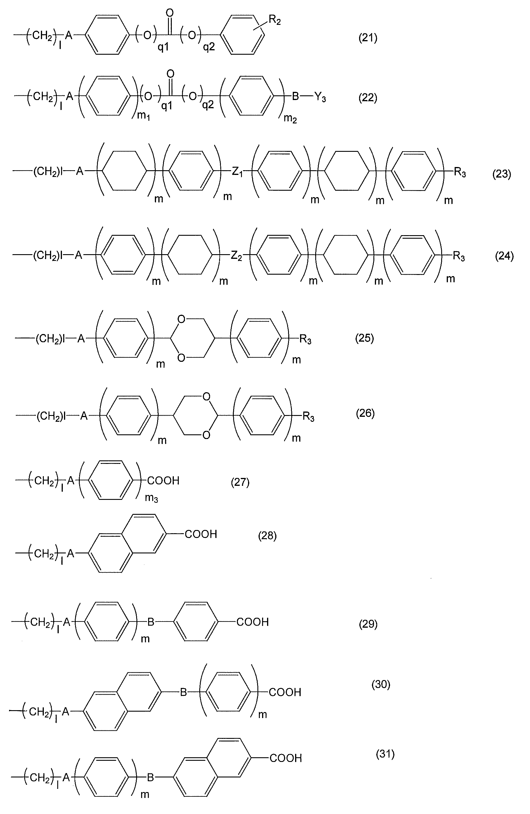
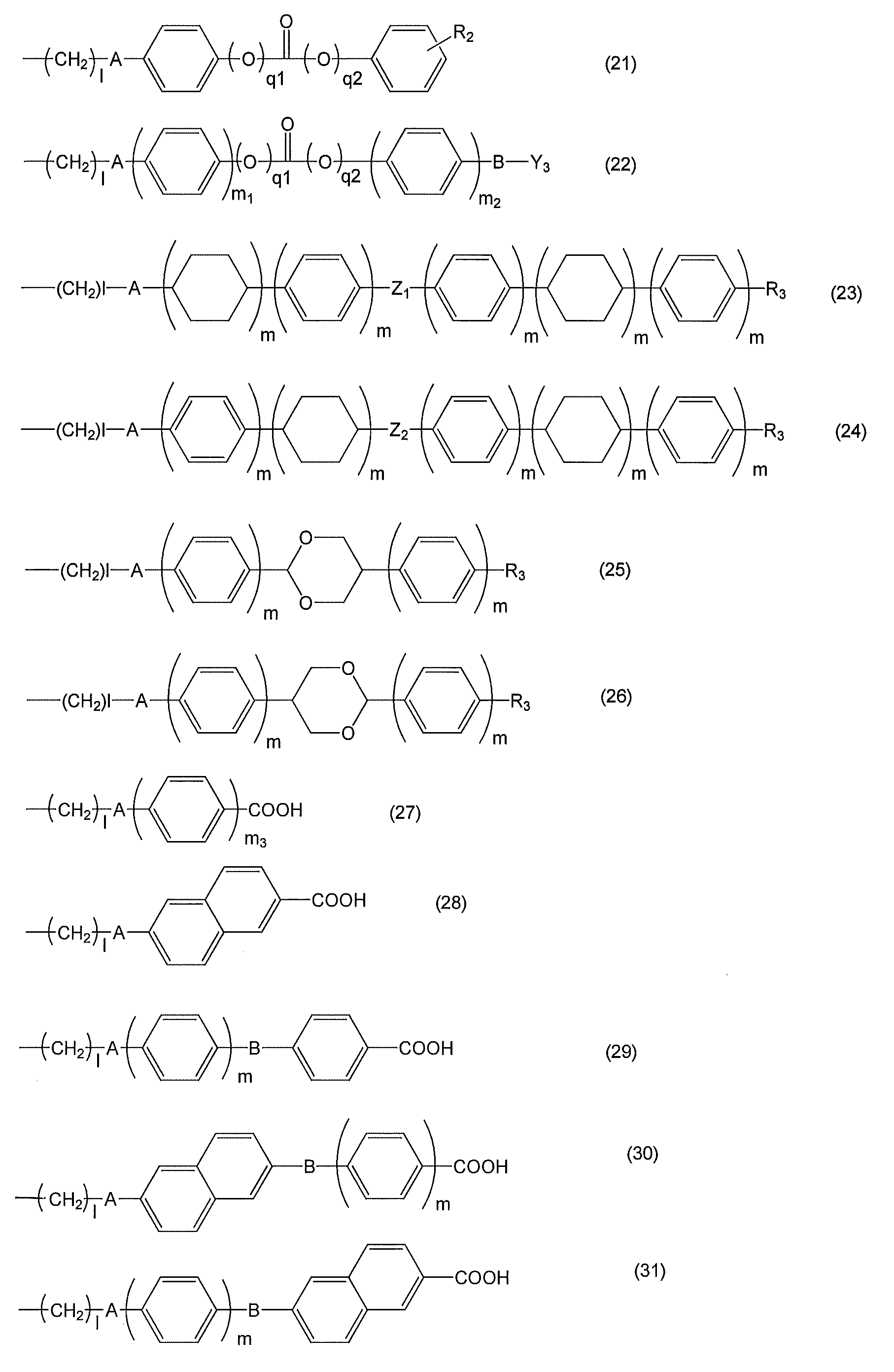
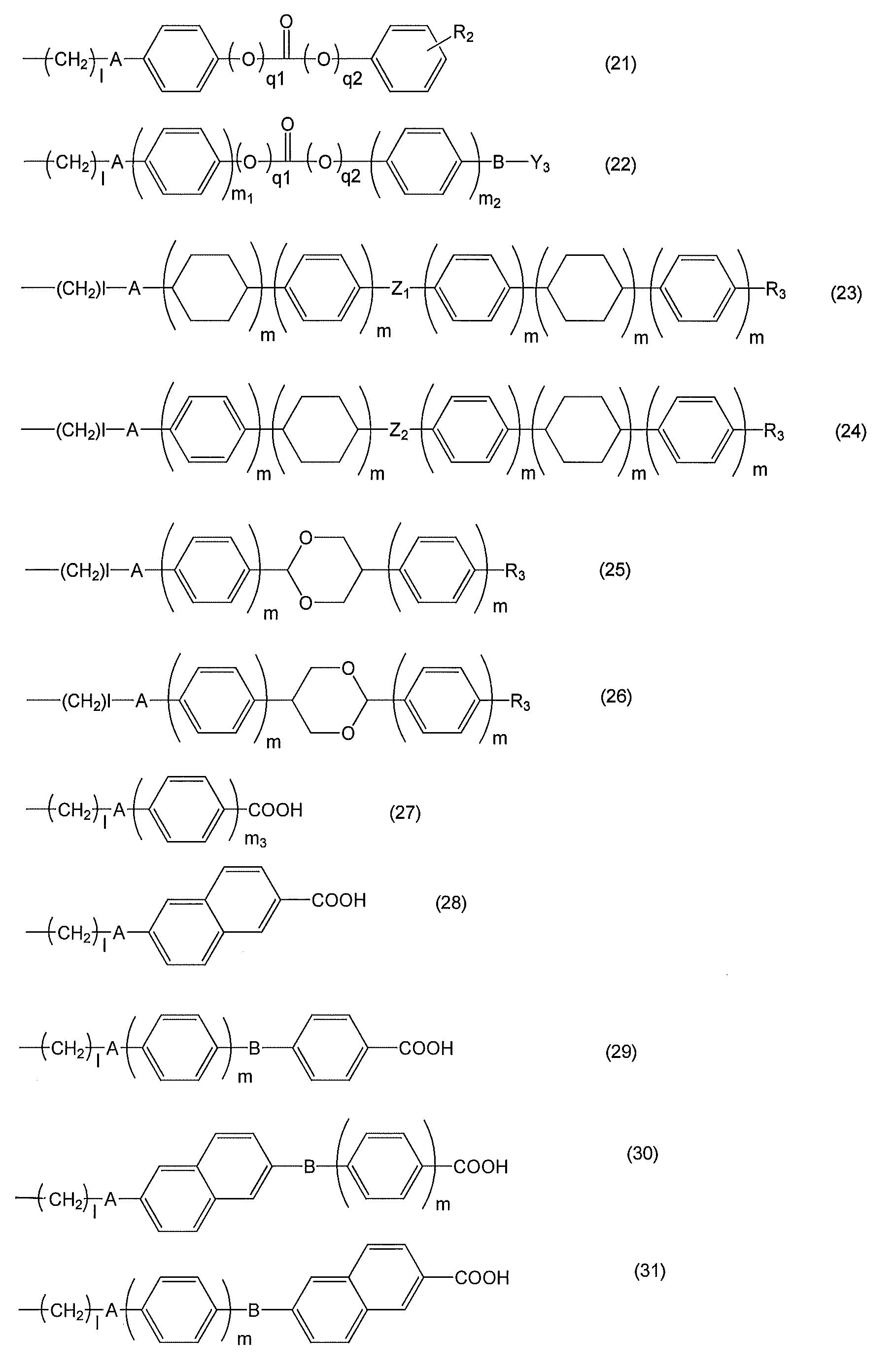
- the polymer may further have any one liquid crystalline side chain selected from the group consisting of the above formulas (21) to (31).
- the material is one selected from the group consisting of a liquid crystal aligning agent, a retardation film, and a hologram, preferably a liquid crystal aligning agent or a retardation film, more preferably A liquid crystal aligning agent, most preferably, a liquid crystal aligning film for a lateral electric field drive type liquid crystal display element is used.
- the method may further include a step of heating the coating film obtained in [III] [II].
- a 1 represents —O—, —COO— or —OCO—, preferably —O—
- n represents an integer of 1 to 8, preferably 6.
- the methylene group is preferably not substituted with the above substituents, preferably R is a methyl group and n 11 and n 12 are 0.
- the polymer may further include any one liquid crystalline side chain selected from the group consisting of the above formulas (21) to (31). .
- the material is one selected from the group consisting of a liquid crystal aligning agent, a retardation film, and a hologram, preferably a liquid crystal aligning agent or a retardation film, more preferably A liquid crystal aligning agent, most preferably, a liquid crystal aligning film for a lateral electric field drive type liquid crystal display element is used.
- the polarized ultraviolet anisotropic material is one selected from the group consisting of a liquid crystal aligning agent, a retardation film, and a hologram, preferably a liquid crystal aligning agent or a retardation film, more preferably a liquid crystal.
- An alignment agent most preferably, a liquid crystal alignment film for a horizontal electric field drive type liquid crystal display element is used.
- a polarized ultraviolet anisotropic material such as a liquid crystal alignment film, which has no or no change in alignment with time, has excellent alignment stability and exhibits anisotropy when irradiated with polarized UV rays, such as a liquid crystal alignment film
- a polarized ultraviolet anisotropic material such as a liquid crystal alignment film
- the present invention can provide a method for producing the above materials and a composition for producing the above materials.
- FIG. 3a shows the optical path figure (FIG. 3a) at the time of performing the holographic exposure of Example 5, and the height (FIG. 3b and FIG. 3c) of two types of surface relief formed by the holograph.
- the present application provides a polarized ultraviolet anisotropic material, a composition for the material, a method for producing the material, a composition used for producing the material, and the like.
- a polarized ultraviolet anisotropic material a composition for the material, a method for producing the material, a composition used for producing the material, and the like.
- This application is a material having a polymer having a side chain represented by the following formula (I), and provides a polarized UV anisotropy material that exhibits anisotropy when irradiated with polarized UV light. To do. *
- a 1 represents —O—, —COO—, —NHCO—, —CONH—, —NHCONH—, —NHCOO—, —OCONH— or —OCO—
- n represents an integer of 1 to 16
- a part of the methylene group (—CH 2 —) is —O—, —COO—, —OOC—, —NHCO—, —CONH—, —NHCONH—, —NHCOO—, —OCONH—, —C ⁇ C— or —C ⁇ C— may be substituted (provided that the methylene group (—CH 2 —) adjacent to A 1 or —O— is not substituted by these groups), and
- R represents an alkyl group having 1 to 3 carbon atoms
- n 11 and n 12 each independently represents an integer of 0 to 4
- R 11 and R 12 each independently represent Straight or branched alky
- a 1 represents —O—, —COO— or —OCO—, preferably —O—, n represents an integer of 1 to 8, preferably 6, and the methylene group is as defined above. It is preferably not substituted with a substituent, R is a methyl group, and n 11 and n 12 are preferably 0.
- the polymer having a side chain represented by the above formula (I) exhibits anisotropy when irradiated with polarized ultraviolet rays.
- a polymer having a side chain represented by the above formula (I) exhibits anisotropy when irradiated with polarized ultraviolet light having a wavelength of 100 to 400 nm.
- the polymer having a side chain represented by the above formula (I) preferably exhibits liquid crystallinity when heated in a temperature range of 40 to 300 ° C. *
- the molecular weight of the polymer (A) of the present invention is GPC (Gel Permeation Chromatography) in consideration of the intended material, for example, the strength of the resulting coating film, the workability during coating film formation, and the uniformity of the coating film.
- the weight average molecular weight measured by the above method is preferably 2,000 to 1,000,000, more preferably 5,000 to 100,000. *
- the polymer having a side chain represented by the above formula (I) preferably further has a liquid crystalline side chain having a mesogenic group exhibiting liquid crystallinity.
- a liquid crystalline side chain exhibiting liquid crystallinity in a temperature range of 40 to 300 ° C. is preferable.
- the target material is a liquid crystal alignment film, it is preferably a liquid crystalline side chain exhibiting liquid crystallinity in a temperature range of 100 to 300 ° C. *
- liquid crystalline side chains may be any one of the liquid crystalline side chains selected from the group consisting of the following formulas (21) to (31).
- a and B are each independently a single bond, —O—, —CH 2 —, —COO—, —OCO—, —CONH—, —NH—CO—, —CH ⁇ CH—CO—O.
- Z 1 and Z 2 are a single bond, — CO—, —CH 2 O—, —CH ⁇ N—, —CF 2 — is represented.
- the material having a polymer having a side chain represented by the formula (I) is one selected from the group consisting of a liquid crystal aligning agent, a retardation film, and a hologram, preferably a liquid crystal aligning agent or a retardation film. It is preferably used for a liquid crystal aligning agent, most preferably a liquid crystal aligning film for a lateral electric field drive type liquid crystal display element.
- composition for polarized ultraviolet anisotropic material having (A) a polymer having a side chain represented by the above formula (I); and (B) an organic solvent. Offer things. *
- the organic solvent used in the composition for polarizing ultraviolet anisotropic material used in the present invention is not particularly limited as long as it is an organic solvent that dissolves the component (A). Specific examples are given below. N, N-dimethylformamide, N, N-dimethylacetamide, N-methyl-2-pyrrolidone, N-methylcaprolactam, 2-pyrrolidone, N-ethylpyrrolidone, N-vinylpyrrolidone, dimethylsulfoxide, tetramethylurea, pyridine, Dimethylsulfone, hexamethylsulfoxide, ⁇ -butyrolactone, 3-methoxy-N, N-dimethylpropanamide, 3-ethoxy-N, N-dimethylpropanamide, 3-butoxy-N, N-dimethylpropanamide, 1,3 -Dimethyl-imidazolidinone, ethyl amyl ketone, methyl nonyl ketone, methyl
- the composition for polarized ultraviolet anisotropic material used in the present invention may contain components other than the components (A) and (B).
- the composition of the present invention may have a polymer exhibiting liquid crystallinity as a component other than the components (A) and (B), or may contain other polymers.
- examples of other polymers include, but are not limited to, poly (meth) acrylate, polyamic acid, polyimide, and the like.
- the content of the other polymer is 0.5 to 90% by mass, preferably 1 to 50% by mass. *
- the composition of the present invention may include, for example, a solvent or a compound that improves the film thickness uniformity and surface smoothness when the composition is applied,
- a compound that improves the adhesion between the liquid crystal alignment film and the substrate can be exemplified, but the present invention is not limited thereto.
- solvents as described above it is preferably 5% by mass to 80% by mass, more preferably 20% by mass, so that the solubility of the entire solvent contained in the composition is not significantly reduced. % To 60% by mass. *
- Examples of compounds that improve film thickness uniformity and surface smoothness include fluorine-based surfactants, silicone-based surfactants, and nonionic surfactants. More specifically, for example, Ftop (registered trademark) 301, EF303, EF352 (manufactured by Tochem Products), MegaFac (registered trademark) F171, F173, R-30 (manufactured by DIC), Florard FC430, FC431 (Manufactured by Sumitomo 3M), Asahi Guard (registered trademark) AG710 (manufactured by Asahi Glass Company), Surflon (registered trademark) S-382, SC101, SC102, SC103, SC104, SC105, SC106 (manufactured by AGC Seimi Chemical Co., Ltd.) It is done.
- the proportion of these surfactants to be used is preferably 0.01 to 2 parts by mass, more preferably 0.01 to 100 parts by mass of the component (A) in the composition.
- the amount is
- the compound that improves the adhesion between the liquid crystal alignment film and the substrate include the following functional silane-containing compounds.
- the material is a liquid crystal alignment film or the like
- the following phenotypes are used for the purpose of preventing the deterioration of the electrical characteristics due to the backlight when the liquid crystal display element is constructed in addition to improving the adhesion between the substrate and the liquid crystal alignment film.
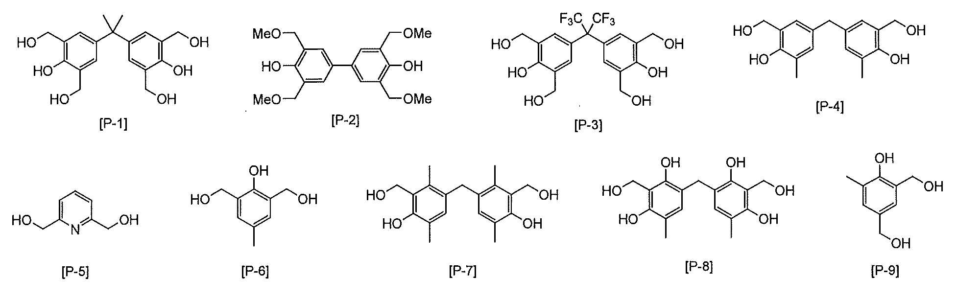
- Additives for plast-based or epoxy group-containing compounds may be included in the composition. Specific phenoplast additives are shown below, but are not limited to this structure. *
- Specific epoxy group-containing compounds include ethylene glycol diglycidyl ether, polyethylene glycol diglycidyl ether, propylene glycol diglycidyl ether, tripropylene glycol diglycidyl ether, polypropylene glycol diglycidyl ether, neopentyl glycol diglycidyl ether, 1,6 -Hexanediol diglycidyl ether, glycerin diglycidyl ether, 2,2-dibromoneopentyl glycol diglycidyl ether, 1,3,5,6-tetraglycidyl-2,4-hexanediol, N, N, N ', N ', -Tetraglycidyl-m-xylenediamine, 1,3-bis (N, N-diglycidylaminomethyl) cyclohexane, N, N, N', N ',-tetraglycidyl-4, '- diaminodip
- the amount used is 0.1 to 30 parts by mass with respect to 100 parts by mass of the component (A) of the polymer contained in the composition. It is preferable that the amount is 1 to 20 parts by mass.
- a photosensitizer can also be used as an additive. Colorless and triplet sensitizers are preferred.
- photosensitizers aromatic nitro compounds, coumarin (7-diethylamino-4-methylcoumarin, 7-hydroxy4-methylcoumarin), ketocoumarin, carbonylbiscoumarin, aromatic 2-hydroxyketone, and amino-substituted, Aromatic 2-hydroxyketones (2-hydroxybenzophenone, mono- or di-p- (dimethylamino) -2-hydroxybenzophenone), acetophenone, anthraquinone, xanthone, thioxanthone, benzanthrone, thiazoline (2-benzoylmethylene-3- Methyl- ⁇ -naphthothiazoline, 2- ( ⁇ -naphthoylmethylene) -3-methylbenzothiazoline, 2- ( ⁇ -naphthoylmethylene) -3-methylbenzothiazoline, 2- (4-biphenoy
- aromatic 2-hydroxyketone (benzophenone), coumarin, ketocoumarin, carbonylbiscoumarin, acetophen Non, anthraquinone, xanthone, thioxanthone, and acetophenone Straight tar.
- the composition may contain various compounds for the purpose of changing the properties of the obtained material.
- the material is a liquid crystal alignment film
- the electrical properties such as the dielectric constant and conductivity of the liquid crystal alignment film, the dielectric or conductive material, and the hardness of the film when the liquid crystal alignment film is formed
- a crosslinkable compound may be added.
- the polarized ultraviolet anisotropic material of the present invention can be produced, for example, by the following method.
- [I] (A) a polymer having a side chain represented by the above formula (I) (wherein A 1 , n, X, and R have the same definition as above); and (B) an organic solvent; Applying a composition for polarizing ultraviolet anisotropic material having a coating on a substrate to form a coating film; and [II] irradiating the coating film obtained in [I] with polarized ultraviolet light.
- a polarized ultraviolet anisotropic material having an orientation control ability can be obtained.
- the (A) polymer and (B) organic solvent and the composition containing them are as described above.
- the method may further include a step of heating the coating film obtained in [III] [II].
- a substrate having a conductive film is preferably used as the substrate [I].
- the above [I] and [II], and in some cases [III], may be performed using a substrate (second substrate) with or without a conductive film.
- the first and second substrates obtained above are arranged so that the liquid crystal alignment films of the first and second substrates face each other through the liquid crystal. And obtaining a liquid crystal display element. Thereby, a liquid crystal display element can be obtained.
- Step [I] is a step of applying the composition described above to a substrate to form a coating film.
- the substrate is not particularly limited, but is preferably selected depending on the target material.
- a liquid crystal alignment film particularly a liquid crystal alignment film for a liquid crystal display element
- the liquid crystal display element to be manufactured is a transmissive type
- a glass substrate or a plastic substrate such as an acrylic substrate or a polycarbonate substrate can be used.
- an opaque substrate such as a silicon wafer can also be used.
- the substrate may have a conductive film.
- the conductive film include, but are not limited to, ITO (Indium Tin Oxide) and IZO (Indium Zinc Oxide) when the liquid crystal display element is a transmission type.
- examples of the conductive film include a material that reflects light such as aluminum, but are not limited thereto.
- a method for forming a conductive film on a substrate a conventionally known method can be used. *
- the polymer (A) includes a photoreactive side chain monomer having a side chain represented by the above formula (I) and, optionally, the above formulas (21) to (31). It can be obtained by polymerizing a liquid crystalline side chain monomer having a side chain represented by The photoreactive side chain monomer having a side chain represented by the formula (I) has a side chain represented by the formula (I) at the side chain site of the polymer when a polymer is formed. A monomer that can form a polymer.
- photoreactive side chain monomer examples include radical polymerizable groups such as hydrocarbon, (meth) acrylate, itaconate, fumarate, maleate, ⁇ -methylene- ⁇ -butyrolactone, styrene, vinyl, maleimide, norbornene, etc. And a structure having a polymerizable group composed of at least one selected from the group consisting of siloxane and a side chain represented by the side chain represented by the above formula (I). *
- the liquid crystalline side chain monomer is a monomer in which a polymer derived from the monomer exhibits liquid crystallinity and the polymer can form a mesogenic group at a side chain site.
- a mesogenic group having a side chain even if it is a group having a mesogen structure alone such as biphenyl or phenylbenzoate, or a group having a mesogen structure by hydrogen bonding between side chains such as benzoic acid Good.
- the mesogenic group possessed by the side chain the following structure is preferable.
- liquid crystalline side chain monomers include hydrocarbon, (meth) acrylate, itaconate, fumarate, maleate, ⁇ -methylene- ⁇ -butyrolactone, styrene, vinyl, maleimide, norbornene and other radical polymerizable groups and siloxane
- a structure having a polymerizable group composed of at least one selected from the group consisting of and a side chain composed of at least one of the above formulas (21) to (31) is preferable.
- the polymer can be obtained by the polymerization reaction of the photoreactive side chain monomer described above. *
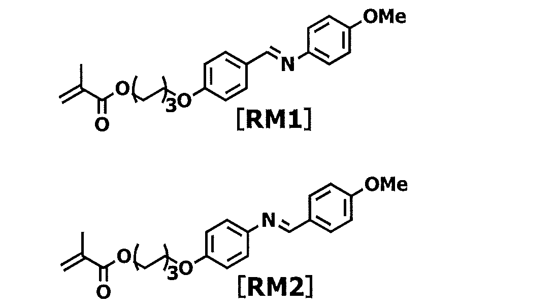
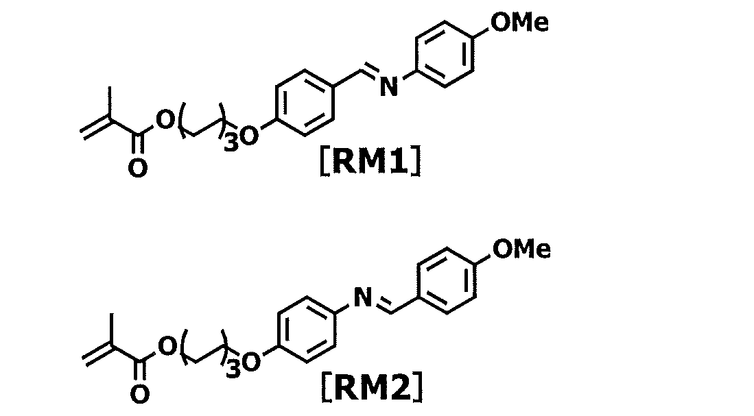
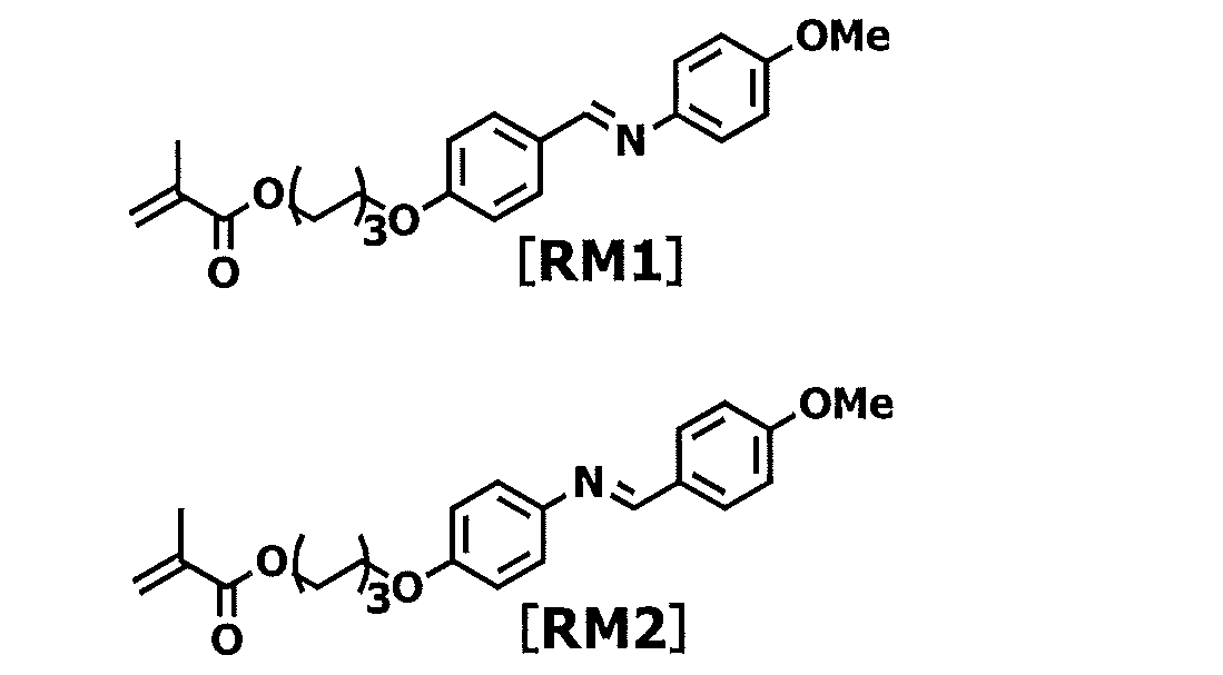
- the (A) polymer of the present invention can be produced from a composition for producing a polarized ultraviolet anisotropic material having a monomer represented by the following formula [RM1] or [RM2].
- the present invention also provides a composition for producing the polarized ultraviolet anisotropic material.
- the polymer (A) of the present invention is a copolymer of a photoreactive side chain monomer that does not exhibit liquid crystallinity and a liquid crystalline side chain monomer, or a photoreactive side chain monomer that exhibits liquid crystallinity and a liquid crystalline side. It can be obtained by copolymerization with chain monomers. Furthermore, it can be copolymerized with other monomers as long as the liquid crystallinity is not impaired.
- Examples of other monomers include industrially available monomers capable of radical polymerization reaction. Specific examples of other monomers include unsaturated carboxylic acid, acrylic ester compound, methacrylic ester compound, maleimide compound, acrylonitrile, maleic anhydride, styrene compound and vinyl compound. *
- the unsaturated carboxylic acid include acrylic acid, methacrylic acid, itaconic acid, maleic acid, fumaric acid and the like.
- acrylic acid ester compounds include methyl acrylate, ethyl acrylate, isopropyl acrylate, benzyl acrylate, naphthyl acrylate, anthryl acrylate, anthryl methyl acrylate, phenyl acrylate, 2,2,2-trifluoroethyl acrylate, tert-butyl acrylate Cyclohexyl acrylate, isobornyl acrylate, 2-methoxyethyl acrylate, methoxytriethylene glycol acrylate, 2-ethoxyethyl acrylate, tetrahydrofurfuryl acrylate, 3-methoxybutyl acrylate, 2-methyl-2-adamantyl acrylate, 2-propyl -2-adamantyl acrylate, 8-methyl-8-tricyclodec
- methacrylic acid ester compounds include methyl methacrylate, ethyl methacrylate, isopropyl methacrylate, benzyl methacrylate, naphthyl methacrylate, anthryl methacrylate, anthryl methyl methacrylate, phenyl methacrylate, 2,2,2-trifluoroethyl methacrylate, tert-butyl methacrylate.
- Cyclohexyl methacrylate isobornyl methacrylate, 2-methoxyethyl methacrylate, methoxytriethylene glycol methacrylate, 2-ethoxyethyl methacrylate, tetrahydrofurfuryl methacrylate, 3-methoxybutyl methacrylate, 2-methyl-2-adamantyl methacrylate, 2-propyl -2-Adamantyl methacrylate, 8-methyl 8 tricyclodecyl methacrylate, and, 8-ethyl-8-tricyclodecyl methacrylate.
- (Meth) acrylate compounds having a cyclic ether group such as glycidyl (meth) acrylate, (3-methyl-3-oxetanyl) methyl (meth) acrylate, and (3-ethyl-3-oxetanyl) methyl (meth) acrylate are also used. be able to. *
- Examples of the vinyl compound include vinyl ether, methyl vinyl ether, benzyl vinyl ether, 2-hydroxyethyl vinyl ether, phenyl vinyl ether, and propyl vinyl ether.
- Examples of the styrene compound include styrene, methylstyrene, chlorostyrene, bromostyrene, and the like.
- Examples of maleimide compounds include maleimide, N-methylmaleimide, N-phenylmaleimide, and N-cyclohexylmaleimide. *
- the method for producing the polymer (A) of the present embodiment is not particularly limited, and a general-purpose method handled industrially can be used. Specifically, it can be produced by cationic polymerization, radical polymerization, or anionic polymerization using a vinyl group of a liquid crystalline side chain monomer or photoreactive side chain monomer. Among these, radical polymerization is particularly preferable from the viewpoint of ease of reaction control. *
- RAFT reversible addition-cleavage chain transfer
- the radical thermal polymerization initiator is a compound that generates radicals by heating to a decomposition temperature or higher.
- radical thermal polymerization initiators include ketone peroxides (methyl ethyl ketone peroxide, cyclohexanone peroxide, etc.), diacyl peroxides (acetyl peroxide, benzoyl peroxide, etc.), hydroperoxides (hydrogen peroxide).
- the radical photopolymerization initiator is not particularly limited as long as it is a compound that initiates radical polymerization by light irradiation.
- examples of such radical photopolymerization initiators include benzophenone, Michler's ketone, 4,4′-bis (diethylamino) benzophenone, xanthone, thioxanthone, isopropylxanthone, 2,4-diethylthioxanthone, 2-ethylanthraquinone, acetophenone, 2-hydroxy- 2-methylpropiophenone, 2-hydroxy-2-methyl-4′-isopropylpropiophenone, 1-hydroxycyclohexyl phenyl ketone, isopropyl benzoin ether, isobutyl benzoin ether, 2,2-diethoxyacetophenone, 2,2- Dimethoxy-2-phenylacetophenone, camphorquinone, benzanthrone, 2-methyl-1- [4- (methylthio
- the radical polymerization method is not particularly limited, and an emulsion polymerization method, suspension polymerization method, dispersion polymerization method, precipitation polymerization method, bulk polymerization method, solution polymerization method and the like can be used. *
- the organic solvent used for the polymerization reaction of the photosensitive side chain polymer capable of exhibiting liquid crystallinity is not particularly limited as long as the generated polymer is soluble. Specific examples are given below. *
- organic solvents may be used alone or in combination. Furthermore, even if it is a solvent which does not dissolve the polymer
- the polymerization temperature at the time of radical polymerization can be selected from 30 ° C. to 150 ° C., but is preferably in the range of 50 ° C. to 100 ° C.
- the reaction can be carried out at any concentration, but if the concentration is too low, it is difficult to obtain a high molecular weight polymer, and if the concentration is too high, the viscosity of the reaction solution becomes too high and uniform stirring is difficult. Therefore, the monomer concentration is preferably 1% by mass to 50% by mass, more preferably 5% by mass to 30% by mass.
- the initial stage of the reaction is carried out at a high concentration, and then an organic solvent can be added. *
- the molecular weight of the obtained polymer is decreased when the ratio of the radical polymerization initiator is large relative to the monomer, and the molecular weight of the obtained polymer is increased when the ratio is small, the ratio of the radical initiator is
- the content is preferably 0.1 mol% to 10 mol% with respect to the monomer to be polymerized. Further, various monomer components, solvents, initiators and the like can be added during the polymerization.
- the reaction solution is preferably poured into a poor solvent to precipitate the obtained polymer.
- the poor solvent used for precipitation include methanol, acetone, hexane, heptane, butyl cellosolve, heptane, methyl ethyl ketone, methyl isobutyl ketone, ethanol, toluene, benzene, diethyl ether, methyl ethyl ether, and water.
- the polymer deposited in a poor solvent and collected can be collected by filtration, and then dried at normal temperature or reduced pressure at room temperature or by heating.
- the polymer collected by precipitation is redissolved in an organic solvent and then collected by reprecipitation is repeated 2 to 10 times, impurities in the polymer can be reduced.
- the poor solvent at this time include alcohols, ketones, hydrocarbons and the like, and it is preferable to use three or more kinds of poor solvents selected from these because purification efficiency is further improved.
- the composition of the present invention is preferably prepared as a coating solution so as to be suitable for forming a liquid crystal alignment film.
- the composition of the present invention is preferably prepared as a solution in which (A) the components of the polymer and others are dissolved in an organic solvent.
- (A) polymer component and others refer to a polymer having a side chain represented by formula (I) and a resin component containing other polymers.
- the content of the component (A) is 1 to 20% by mass, preferably 3 to 15% by mass, more preferably 3 to 10% by mass. *
- the method for applying the above-described composition onto the substrate is not particularly limited.
- the application method is generally industrially performed by screen printing, offset printing, flexographic printing, or an inkjet method.
- Other coating methods include a dipping method, a roll coater method, a slit coater method, a spinner method (rotary coating method), or a spray method, and these may be used depending on the purpose. *
- the solvent is evaporated at 50 to 200 ° C., preferably 50 to 150 ° C. by a heating means such as a hot plate, a heat circulation oven or an IR (infrared) oven, and the coating film is formed.
- a heating means such as a hot plate, a heat circulation oven or an IR (infrared) oven
- the thickness of the coating film depends on the target material, but it is 5 to 10,000 nm, preferably 10 to 5000 nm.
- it is preferably 5 to 300 nm, preferably 10 to 200 nm, and when used as a retardation film or hologram, 500 to 10,000 nm is preferable, and 500 to 5000 nm is more preferable.
- Step [II] the coating film obtained in Step [I] is irradiated with polarized ultraviolet rays.
- the substrate is irradiated with polarized ultraviolet rays through a polarizing plate from a certain direction.
- ultraviolet rays to be used ultraviolet rays having a wavelength in the range of 100 nm to 400 nm can be used.
- the optimum wavelength is selected through a filter or the like depending on the type of coating film to be used.
- ultraviolet rays having a wavelength in the range of 290 nm to 400 nm can be selected and used so that the photoisomerization reaction can be selectively induced.
- the ultraviolet light for example, light emitted from a high-pressure mercury lamp can be used.
- the irradiation amount of polarized ultraviolet rays depends on the coating film to be used.
- the amount of irradiation is polarized ultraviolet light that realizes the maximum value of ⁇ A (hereinafter also referred to as ⁇ Amax), which is the difference between the ultraviolet light absorbance in a direction parallel to the polarization direction of polarized ultraviolet light and the ultraviolet light absorbance in a direction perpendicular to the polarization direction of the polarized ultraviolet light.
- the amount is preferably in the range of 1% to 70%, more preferably in the range of 1% to 50%.
- step [III] the coating film irradiated with ultraviolet rays polarized in step [II] is heated.
- An orientation control ability can be imparted to the coating film by heating. Heating can be performed using a heating means such as a hot plate, a heat circulation type oven, or an IR (infrared) type oven.
- the heating temperature can be determined in consideration of the temperature at which the liquid crystallinity of the coating film used is developed.
- the thickness of the coating film formed after heating is preferably the same as in step [I]. *
- the manufacturing method of this invention can implement
- a liquid crystal alignment film for liquid crystal display elements can be obtained by using step [IV].
- a substrate having a conductive film for driving a lateral electric field is used as the substrate, and a liquid crystal alignment film is formed on the conductive film for driving a lateral electric field by performing the above [I] to [III].
- a substrate (first substrate) can be obtained.
- a liquid crystal alignment film having no conductive film is obtained.
- An attached substrate (second substrate) can be obtained.
- the first and second substrates are arranged to face each other with the liquid crystal alignment film facing each other through the liquid crystal, and a liquid crystal cell is manufactured by a known method. This is a step of manufacturing a liquid crystal display element.
- the first and second substrates described above are prepared, spacers are dispersed on the liquid crystal alignment film of one substrate, and the liquid crystal alignment film surface is on the inside.
- the other substrate is bonded and the liquid crystal is injected under reduced pressure, or the liquid crystal is dropped on the liquid crystal alignment film surface on which the spacers are dispersed, and then the substrate is bonded and sealed.
- Etc. can be illustrated.
- the diameter of the spacer at this time is preferably 1 ⁇ m to 30 ⁇ m, more preferably 2 ⁇ m to 10 ⁇ m. This spacer diameter determines the distance between the pair of substrates that sandwich the liquid crystal layer, that is, the thickness of the liquid crystal layer.
- substrate with a coating film irradiates the polarized ultraviolet-ray, after apply
- a highly efficient introduction of anisotropy into the side chain polymer film is realized, and a substrate with a liquid crystal alignment film having a liquid crystal alignment control ability can be manufactured.
- the present invention will be specifically described using examples, but the present invention is not limited to the examples.
- Example 1> [Preparation of liquid crystal cell] Using the liquid crystal aligning agent (A1) obtained in ⁇ Synthesis Example 3>, a liquid crystal cell was prepared according to the following procedure.
- the substrate was a glass substrate having a size of 30 mm ⁇ 40 mm and a thickness of 0.7 mm, on which comb-like pixel electrodes formed by patterning an ITO film were arranged.
- the pixel electrode has a comb-like shape configured by arranging a plurality of dog-shaped electrode elements whose central portion is bent. The width in the short direction of each electrode element is 10 ⁇ m, and the distance between the electrode elements is 20 ⁇ m.
- each pixel Since the pixel electrode forming each pixel is formed by arranging a plurality of bent-shaped electrode elements in the central portion, the shape of each pixel is not rectangular, but in the central portion like the electrode elements. It has a shape that bends and resembles a bold-faced koji.
- Each pixel is divided into upper and lower portions with a central bent portion as a boundary, and has a first region on the upper side of the bent portion and a second region on the lower side. When the first region and the second region of each pixel are compared, the formation directions of the electrode elements of the pixel electrodes constituting them are different.
- the electrode element of the pixel electrode is formed to form an angle of + 15 ° (clockwise) in the first region of the pixel, and in the second region of the pixel.
- the electrode elements of the pixel electrode are formed so as to form an angle of ⁇ 15 ° (clockwise). That is, in the first region and the second region of each pixel, the directions of the rotation operation (in-plane switching) of the liquid crystal induced by the voltage application between the pixel electrode and the counter electrode are mutually in the substrate plane. It is comprised so that it may become a reverse direction.
- the liquid crystal aligning agent (A1) obtained in ⁇ Synthesis Example 3> was spin-coated on the prepared substrate with electrodes. Subsequently, it dried for 90 second with a 70 degreeC hotplate, and formed the liquid crystal aligning film with a film thickness of 100 nm. Next, the coating film surface was irradiated with ultraviolet rays of 313 nm via a polarizing plate and then heated on a hot plate at 110 ° C. for 10 minutes to obtain a substrate with a liquid crystal alignment film. Further, a coating film was similarly formed on a glass substrate having a columnar spacer with a height of 4 ⁇ m on which no electrode was formed as a counter substrate, and an orientation treatment was performed.
- a sealant (XN-1500T manufactured by Kyoritsu Chemical Co., Ltd.) was printed on the liquid crystal alignment film of one substrate. Next, the other substrate was bonded so that the liquid crystal alignment film faces each other and the alignment direction was 0 °, and then the sealing agent was thermally cured to produce an empty cell.
- a liquid crystal cell having a configuration of an IPS (In-Plane Switching) mode liquid crystal display element is injected into this empty cell by a vacuum injection method by injecting liquid crystal MLC-2041 (manufactured by Merck), sealing the injection port. Obtained. When the obtained liquid crystal cell was baked at 120 ° C. for 30 minutes, it was confirmed that good alignment was exhibited. *
- Example 2> [Preparation of liquid crystal cell] ⁇ Example 1 except that the liquid crystal aligning agent (A2) obtained in ⁇ Synthesis Example 4> was used instead of the liquid crystal aligning agent (A1) in ⁇ Example 1>.
- a liquid crystal cell was produced by the same method as above. When the obtained liquid crystal cell was baked at 120 ° C. for 30 minutes, it was confirmed to show good alignment. *
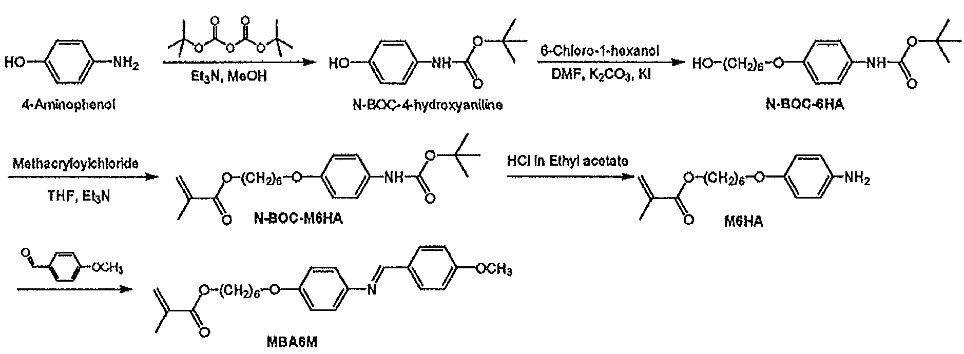
- N-BOC-6HA 17.5 g (83.7 mmol) of N-BOC-4-hydroxyaniline is placed in a 300 ml three-flask and dissolved by adding 100 ml of dimethylformamide (DMF). Chloro-1-hexanol (13.7 g, 102 mmol), K 2 CO 3 (22.5 g, 163 mmol) and KI were added in 4 cups of spatula and refluxed in an oil bath set at 100 ° C. for 3 hours. The completion of the reaction was confirmed by TLC, the reaction solution was extracted with diethyl ether (100 ml ⁇ 3 times), and the solvent was distilled off under reduced pressure.
- DMF dimethylformamide
- N-BOC-M6HA ⁇ Synthesis of N-BOC-M6HA
- THF tetrahydrofuran
- Et 3 N triethylamine
- polymerization Hydroquinone as an inhibitor was added for 4 cups of spatula and stirred.
- Et 3 N triethylamine
- methacrylic acid chloride was diluted with 150 ml of THF and slowly added dropwise with a dropping funnel. The mixture was stirred for 1 hour in an ice bath and then stirred at room temperature for about 16 hours.
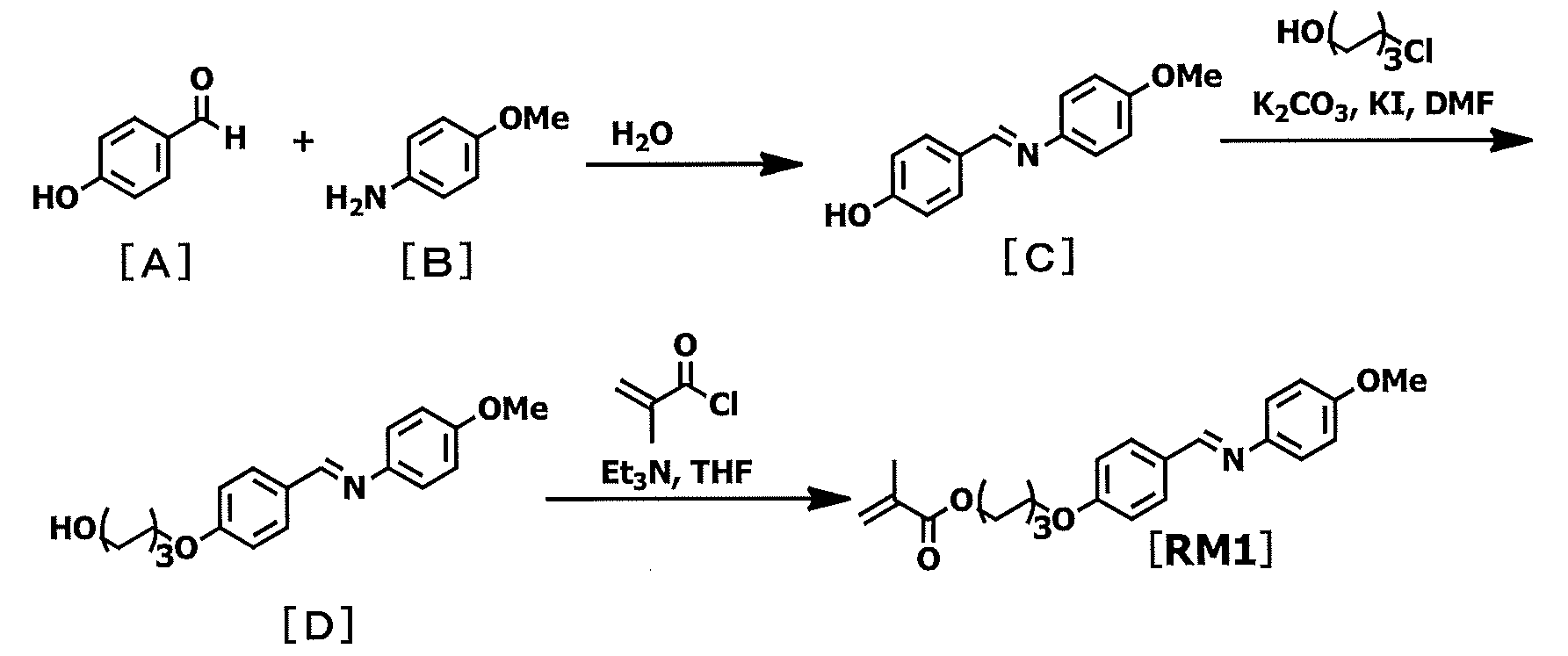
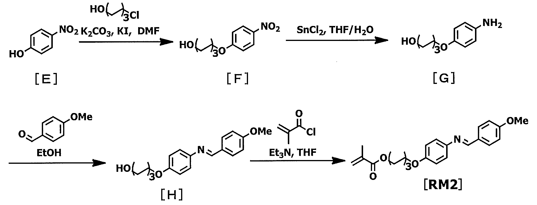
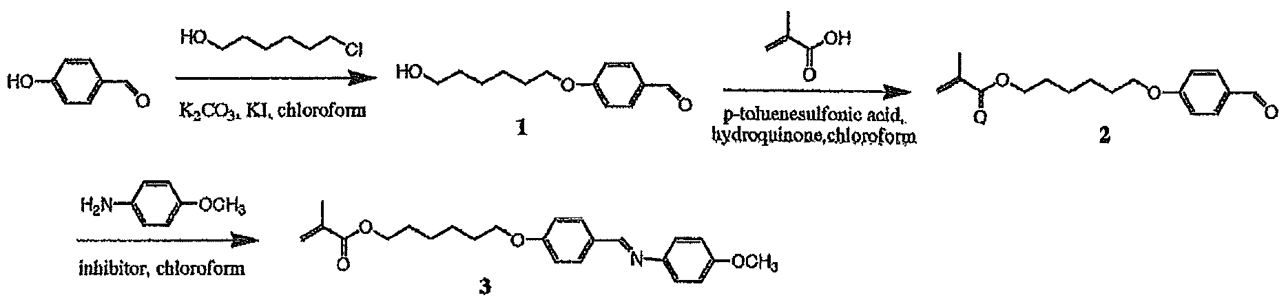
- Synthesis Example 6 ⁇ Synthesis of RM1 >> RM1 (abbreviated as “Compound 3” or “3” in the following scheme and in this Synthesis Example 6) was synthesized according to the following scheme. *
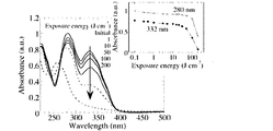
- FIG. 1 is a diagram showing a change in absorption spectrum when a polymer P1 thin film is irradiated with light of 313 nm (intensity: 10 mW / cm 2 ). Varying the amount of irradiation from 0 J / cm 2 to 300 J / cm 2, was observed that the absorption at a wavelength of 283nm and 332nm is smaller changes.
- the change was gradual until the irradiation dose reached 50 J / cm 2, but when the irradiation dose exceeded 100 J / cm 2 , the peak at 332 nm disappeared and a new peak appeared around 260 nm.
- the thin film was transparent in the visible range. Further, the thin film after irradiation (irradiation amount> 100 J / cm 2 ) became insoluble in the organic solvent.
- photoisomerization represented by the following formula (X) is the main part of the photoreaction, but when further irradiated, photoisomerization and other photoreactions such as photocrosslinking have occurred. Conceivable.
- FIG. 2 is a diagram showing a change in polarization absorption spectrum of a P1 film irradiated with 10 J / cm 2 of linearly polarized ultraviolet light 313 nm. After irradiation, the absorbance As in the direction perpendicular to the electric field vector of polarized ultraviolet light increased, but the absorbance Ap in the direction parallel to the electric field vector of polarized ultraviolet light decreased.
- FIG. 3b shows a polarization optical microscope image of an intensity holographic exposure P1 film using two p-polarized (pp) beams for 210 seconds.
- the periodic emission line ( ⁇ 3.15 ⁇ m) coincided with the molecular reorientation region perpendicular to the lattice vector.
- the surface undulation was formed at a height of 78 nm. Similar results were obtained when two s-polarized (ss) intensity holography and two circularly polarized (2CP) were used. However, the height of the surface relief depends on the polarization, and in the case of ss, the height was 20 nm, and in the case of 2CP, the height was 60 nm. *
- Polarization holography simultaneously formed both surface relief formation and periodic molecular reorientation according to the interference polarization pattern.
- ⁇ CP circularly polarized beams having opposite circularly polarized light
- ⁇ 1.58 ⁇ m
Landscapes
- Physics & Mathematics (AREA)
- Nonlinear Science (AREA)
- Optics & Photonics (AREA)
- General Physics & Mathematics (AREA)
- Chemical & Material Sciences (AREA)
- Crystallography & Structural Chemistry (AREA)
- Mathematical Physics (AREA)
- Spectroscopy & Molecular Physics (AREA)
- Medicinal Chemistry (AREA)
- Chemical Kinetics & Catalysis (AREA)
- Organic Chemistry (AREA)
- Polymers & Plastics (AREA)
- Health & Medical Sciences (AREA)
- Liquid Crystal (AREA)
- Addition Polymer Or Copolymer, Post-Treatments, Or Chemical Modifications (AREA)
- Polarising Elements (AREA)
- Holo Graphy (AREA)
Abstract
Description



ロピオン酸、3-メトキシプロピオン酸、3-メトキシプロピオン酸プロピル、3-メトキシプロピオン酸ブチル、1-メトキシ-2-プロパノール、1-エトキシ-2-プロパノール、1-ブトキシ-2-プロパノール、1-フェノキシ-2-プロパノール、プロピレングリコールモノアセテート、プロピレングリコールジアセテート、プロピレングリコール-1-モノメチルエーテル-2-アセテート、プロピレングリコール-1-モノエチルエーテル-2-アセテート、ジプロピレングリコール、2-(2-エトキシプロポキシ)プロパノール、乳酸メチルエステル、乳酸エチルエステル、乳酸n-プロピルエステル、乳酸n-ブチルエステル、乳酸イソアミルエステル等の低表面張力を有する溶媒等が挙げられる。
性側鎖モノマー] 液晶性側鎖モノマーとは、該モノマー由来の高分子が液晶性を発現し、該高分子が側鎖部位にメソゲン基を形成することができるモノマーのことである。 側鎖の有するメソゲン基として、ビフェニルやフェニルベンゾエートなどの単独でメソゲン構造となる基であっても、安息香酸などのように側鎖同士が水素結合することでメソゲン構造となる基であってもよい。側鎖の有するメソゲン基としては下記の構造が好ましい。

ルアセトアミド、N-メチル-2-ピロリドン、N-エチル-2-ピロリドン、N-メチルカプロラクタム、ジメチルスルホキシド、テトラメチル尿素、ピリジン、ジメチルスルホン、ヘキサメチルスルホキシド、γ-ブチロラクトン、イソプロピルアルコール、メトキシメチルペンタノール、ジペンテン、エチルアミルケトン、メチルノニルケトン、メチルエチルケトン、メチルイソアミルケトン、メチルイソプロピルケトン、メチルセルソルブ、エチルセルソルブ、メチルセロソルブアセテート、エチルセロソルブアセテート、ブチルカルビトール、エチルカルビトール、エチレングリコール、エチレングリコールモノアセテート、エチレングリコールモノイソプロピルエーテル、エチレングリコールモノブチルエーテル、プロピレングリコール、プロピレングリコールモノアセテート、プロピレングリコールモノメチルエーテル、プロピレングリコール-tert-ブチルエーテル、ジプロピレングリコールモノメチルエーテル、ジエチレングリコール、ジエチレングリコールモノアセテート、ジエチレングリコールジメチルエーテル、ジプロピレングリコールモノアセテートモノメチルエーテル、ジプロピレングリコールモノメチルエーテル、ジプロピレングリコールモノエチルエーテル、ジプロピレングリコールモノアセテートモノエチルエーテル、ジプロピレングリコールモノプロピルエーテル、ジプロピレングリコールモノアセテートモノプロピルエーテル、3-メチル-3-メトキシブチルアセテート、トリプロピレングリコールメチルエーテル、3-メチル-3-メトキシブタノール、ジイソプロピルエーテル、エチルイソブチルエーテル、ジイソブチレン、アミルアセテート、ブチルブチレート、ブチルエーテル、ジイソブチルケトン、メチルシクロへキセン、プロピルエーテル、ジヘキシルエーテル、ジオキサン、n-へキサン、n-ペンタン、n-オクタン、ジエチルエーテル、シクロヘキサノン、エチレンカーボネート、プロピレンカーボネート、乳酸メチル、乳酸エチル、酢酸メチル、酢酸エチル、酢酸n-ブチル、酢酸プロピレングリコールモノエチルエーテル、ピルビン酸メチル、ピルビン酸エチル、3-メトキシプロピオン酸メチル、3-エトキシプロピオン酸メチルエチル、3-メトキシプロピオン酸エチル、3-エトキシプロピオン酸、3-メトキシプロピオン酸、3-メトキシプロピオン酸プロピル、3-メトキシプロピオン酸ブチル、ジグライム、4-ヒドロキシ-4-メチル-2-ペンタノン、3-メトキシ-N,N-ジメチルプロパンアミド、3-エトキシ-N,N-ジメチルプロパンアミド、3-ブトキシ-N,N-ジメチルプロパンアミド等が挙げられる。

、100℃設定のオイルバスで3時間還流した。TLCで反応の終了を確認し、反応溶液をジエチルエーテルで抽出し(100ml×3回)、溶媒を減圧留去した。シリカゲルカラムクロマトグラフィーで精製し(シリカゲル400g、展開溶媒:酢酸エチル/ヘキサン=1/1)、再結晶することでピンク色がかった白色固体を得た。収量:12.6g;収率:48.8mol%;融点:78℃。



Claims (15)
- 下記式(I)で表される側鎖(式中、A1は-O-、-COO-、-NHCO-、-CONH-、-NHCONH-、-NHCOO-、-OCONH-又は-OCO-を表し、nは1~16の整数を表し、メチレン基(-CH2-)の一部は-O-、-COO-、-OOC-、-NHCO-、-CONH-、-NHCONH-、-NHCOO-、-OCONH-、-C=C-又は-C≡C-に置き換えられてもよく(ただし、A1又は-O-に隣接するメチレン基(-CH2-)は、これらの基に置換されない)、Xは-CH=N-又は-N=CH-を表し、Rは炭素数1~3のアルキル基を表し、n11及びn12は各々独立に0~4の整数を表し、R11及びR12は各々独立に、炭素数1~6個の直鎖又は分岐鎖のアルキル基、ハロゲン原子、ニトロ、シアノ、炭素数1~6個の直鎖又は分岐鎖のアルコキシ基を表す)を有する高分子を有する材料であって、偏光紫外線照射により異方性を示す偏光紫外線異方性材料。

- A1が-O-、-COO-又は-OCO-であり、nが1~8の整数であり、n11及びn12が0であり、R
がメチル基である請求項1記載の材料。 - 前記高分子が、下記式(21)~(31)(式中、A、及びBはそれぞれ独立に、単結合、-O-、-CH2-、-COO-、-OCO-、-CONH-、-NH-CO-、-CH=CH-CO-O-、又は-O-CO-CH=CH-を表す; q1及びq2は一方が1で他方が0である; Y3は、1価のベンゼン環、ナフタレン環、ビフェニル環、フラン環、窒素含有複素環、及び炭素数5~8の脂環式炭化水素、および、それらの組み合わせからなる群から選ばれる基であり、それらに結合する水素原子はそれぞれ独立に-NO2、-CN、ハロゲン基、炭素数1~5のアルキル基、又は炭素数1~5のアルキルオキシ基で置換されても良い; R3は、水素原子、-NO2、-CN、-CH=C(CN)2、-CH=CH-CN、ハロゲン基、1価のベンゼン環、ナフタレン環、ビフェニル環、フラン環、窒素含有複素環、炭素数5~8の脂環式炭化水素、炭素数1~12のアルキル基、又は炭素数1~12のアルコキシ基を表す; lは1~12の整数を表し、mは0から2の整数を表し、但し、式(25)~(26)において、全てのmの合計は2以上であり、式(27)~(28)において、全てのmの合計は1以上であり、m1、m2およびm3は、それぞれ独立に1~3の整数を表す; R2は、水素原子、-NO2、-CN、ハロゲン基、1価のベンゼン環、ナフタレン環、ビフェニル環、フラン環、窒素含有複素環、及び炭素数5~8の脂環式炭化水素、および、アルキル基、又はアルキルオキシ基を表す; Z1、Z2は単結合、-CO-、-CH2O-、-CH=N-、-CF2-を表す。)からなる群から選ばれるいずれか1種の液晶性側鎖をさらに有する請求項1又は2記載の材料。
- 前記材料が、液晶配向剤、位相差膜、及びホログラムからなる群から選ばれる1種に用いられる請求項1~3のいずれか1項記載の材料。
- (A)下記式(I)で表される側鎖(式中、A1は-O-、-COO-、-NHCO-、-CONH-、-NHCONH-、-NHCOO-、-OCONH-又は-OCO-を表し、nは1~16の整数を表し、メチレン基(-CH2-)の一部は-O-、-COO-、-OOC-、-NHCO-、-CONH-、-NHCONH-、-NHCOO-、-OCONH-、-C=C-又は-C≡C-に置き換えられてもよく(ただし、A1又は-O-に隣接するメチレン基(-CH2-)は、これらの基に置換されない)、Xは-CH=N-又は-N=CH-を表し、Rは炭素数1~3のアルキル基を表し、n11及びn12は各々独立に0~4の整数を表し、R11及びR12は各々独立に、炭素数1~6個の直鎖又は分岐鎖のアルキル基、ハロゲン原子、ニトロ、シアノ、炭素数1~6個の直鎖又は分岐鎖のアルコキシ基を表す)を有する高分子;及び (B)有機溶媒を有する偏光紫外線異方性材料用組成物。

- A1が-O-、-COO-又は-OCO-であり、nが1~8の整数であり、n11及びn12が0であり、Rがメチル基である請求項5記載の組成物。
- 前記(A)高分子が、下記式(21)~(31)(式中、A、及びBはそれぞれ独立に、単結合、-O-、-CH2-、-COO-、-OCO-、-CONH-、-NH-CO-、-CH=CH-CO-O-、又は-O-CO-CH=CH-を表す; q1及びq2は一方が1で他方が0である; Y3は、1価のベンゼン環、ナフタレン環、ビフェニル環、フラン環、窒素含有複素環、及び炭素数5~8の脂環式炭化水素、および、それらの組み合わせからなる群から選ばれる基であり、それらに結合する水素原子はそれぞれ独立に-NO2、-CN、ハロゲン基、炭素数1~5のアルキル基、又は炭素数1~5のアルキルオキシ基で置換されても良い; R3は、水素原子、-NO2、-CN、-CH=C(CN)2、-CH=CH-CN、ハロゲン基、1価のベンゼン環、ナフタレン環、ビフェニル環、フラン環、窒素含有複素環、炭素数5~8の脂環式炭化水素、炭素数1~12のアルキル基、又は炭素数1~12のアルコキシ基を表す; lは1~12の整数を表し、mは0から2の整数を表し、但し、式(25)~(26)において、全てのmの合計は2以上であり、式(27)~(28)において、全てのmの合計は1以上であり、m1、m2およびm3は、それぞれ独立に1~3の整数を表す; R2は、水素原子、-NO2、-CN、ハロゲン基、1価のベンゼン環、ナフタレン環、ビフェニル環、フラン環、窒素含有複素環、及び炭素数5~8の脂環式炭化水素、および、アルキル基、又はアルキルオキシ基を表す; Z1、Z2は単結合、-CO-、-CH2O-、-CH=N-、-CF2-を表す。)からなる群から選ばれるいずれか1種の液晶性側鎖をさらに有する請求項5又は6記載の組成物。
- 前記材料が、液晶配向剤、位相差膜、及びホログラムからなる群から選ばれる1種に用いられる請求項5~7のいずれか1項記載の組成物。
- [I] (A)下記式(I)で表される側鎖(式中、A1は-O-、-COO-、-NHCO-、-CONH-、-NHCONH-、-NHCOO-、-OCONH-又は-OCO-を表し、nは1~16の整数を表し、メチレン基(-CH2-)の一部は-O-、-COO-、-OOC-、-NHCO-、-CONH-、-NHCONH-、-NHCOO-、-OCONH-、-C=C-又は-C≡C-に置き換えられてもよく(ただし、A1又は-O-に隣接するメチレン基(-CH2-)は、これらの基に置換されない)、Xは-CH=N-又は-N=CH-を表し、Rは炭素数1~3のアルキル基を表し、n11及びn12は各々独立に0~4の整数を表し、R11及びR12は各々独立に、炭素数1~6個の直鎖又は分岐鎖のアルキル基、ハロゲン原子、ニトロ、シアノ、炭素数1~6個の直鎖又は分岐鎖のアルコキシ基を表す)を有する高分子;及び (B)有機溶媒を有する偏光紫外線異方性材料用組成物を、基板上に塗布して塗膜を形成する工程;及び [II] [I]で得られた塗膜に偏光した紫外線を照射する工程; を有することによって、偏光紫外線照射により異方性を示す偏光紫外線異方性材料を得る、偏光紫外線異方性材料の製造方法。

- [III] [II]で得られた塗膜を加熱する工程;をさらに有する請求項9記載の方法。
- A1が-O-、-COO-又は-OCO-であり、nが1~8の整数であり、n11及びn12が0であり、Rがメチル基である請求項9又は10記載の方法。
- 前記(A)高分子が、下記式(21)~(31)(式中、A、及びBはそれぞれ独立に、単結合、-O-、-CH2-、-COO-、-OCO-、-CONH-、-NH-CO-、-CH=CH-CO-O-、又は-O-CO-CH=CH-を表す; q1及びq2は一方が1で他方が0である; Y3は、1価のベンゼン環、ナフタレン環、ビフェニル環、フラン環、窒素含有複素環、及び炭素数5~8の脂環式炭化水素、および、それらの組み合わせからなる群から選ばれる基であり、それらに結合する水素原子はそれぞれ独立に-NO2、-CN、ハロゲン基、炭素数1~5のアルキル基、又は炭素数1~5のアルキルオキシ基で置換されても良い; R3は、水素原子、-NO2、-CN、-CH=C(CN)2、-CH=CH-CN、ハロゲン基、1価のベンゼン環、ナフタレン環、ビフェニル環、フラン環、窒素含有複素環、炭素数5~8の脂環式炭化水素、炭素数1~12のアルキル基、又は炭素数1~12のアルコキシ基を表す; lは1~12の整数を表し、mは0から2の整数を表し、但し、式(25)~(26)において、全てのmの合計は2以上であり、式(27)~(28)において、全てのmの合計は1以上であり、m1、m2およびm3は、それぞれ独立に1~3の整数を表す; R2は、水素原子、-NO2、-CN、ハロゲン基、1価のベンゼン環、ナフタレン環、ビフェニル環、フラン環、窒素含有複素環、及び炭素数5~8の脂環式炭化水素、および、アルキル基、又はアルキルオキシ基を表す; Z1、Z2は単結合、-CO-、-CH2O-、-CH=N-、-CF2-を表す。)からなる群から選ばれるいずれか1種の液晶性側鎖をさらに有する請求項9~11のいずれか1項記載の方法。

- 前記材料が、液晶配向剤、位相差膜、及びホログラムからなる群から選ばれる1種に用いられる請求項9~12のいずれか1項記載の方法。
- 下記式[RM1]又は[RM2]で表されるモノマーを有する、偏光紫外線異方性材料製造用組成物。
- 前記偏光紫外線異方性材料が、液晶配向剤、位相差膜、及びホログラムからなる群から選ばれる1種に用いられる請求項14記載の組成物。
Priority Applications (3)
| Application Number | Priority Date | Filing Date | Title |
|---|---|---|---|
| JP2015525290A JPWO2015002292A1 (ja) | 2013-07-04 | 2014-07-04 | 偏光紫外線異方性化材料 |
| CN201480048714.8A CN105518036B (zh) | 2013-07-04 | 2014-07-04 | 偏振紫外线各向异性化材料 |
| KR1020167003031A KR102311484B1 (ko) | 2013-07-04 | 2014-07-04 | 편광 자외선 이방성화 재료 |
Applications Claiming Priority (2)
| Application Number | Priority Date | Filing Date | Title |
|---|---|---|---|
| JP2013140466 | 2013-07-04 | ||
| JP2013-140466 | 2013-07-04 |
Publications (1)
| Publication Number | Publication Date |
|---|---|
| WO2015002292A1 true WO2015002292A1 (ja) | 2015-01-08 |
Family
ID=52143861
Family Applications (1)
| Application Number | Title | Priority Date | Filing Date |
|---|---|---|---|
| PCT/JP2014/067894 Ceased WO2015002292A1 (ja) | 2013-07-04 | 2014-07-04 | 偏光紫外線異方性化材料 |
Country Status (5)
| Country | Link |
|---|---|
| JP (1) | JPWO2015002292A1 (ja) |
| KR (1) | KR102311484B1 (ja) |
| CN (1) | CN105518036B (ja) |
| TW (1) | TWI701283B (ja) |
| WO (1) | WO2015002292A1 (ja) |
Cited By (4)
| Publication number | Priority date | Publication date | Assignee | Title |
|---|---|---|---|---|
| JP2017075983A (ja) * | 2015-10-13 | 2017-04-20 | 林テレンプ株式会社 | 光学的異方性素子、液晶配向膜、およびこれらに使用される液晶高分子膜ならびにその製造方法 |
| JP2019085433A (ja) * | 2017-11-01 | 2019-06-06 | 林テレンプ株式会社 | 液晶高分子膜およびその製造方法 |
| KR20190094241A (ko) * | 2017-03-29 | 2019-08-12 | 후지필름 가부시키가이샤 | 위상차 필름의 제조 방법 |
| JP2023088428A (ja) * | 2021-12-15 | 2023-06-27 | 林テレンプ株式会社 | 液晶高分子膜およびその製造方法 |
Families Citing this family (3)
| Publication number | Priority date | Publication date | Assignee | Title |
|---|---|---|---|---|
| WO2017188366A1 (ja) * | 2016-04-28 | 2017-11-02 | 日産化学工業株式会社 | 液晶配向剤、液晶配向膜、液晶表示素子及び新規モノマー |
| KR102030079B1 (ko) * | 2017-06-30 | 2019-10-08 | 주식회사 엘지화학 | 액정 배향제 조성물, 이를 이용한 액정 배향막의 제조 방법, 및 이를 이용한 액정 배향막 |
| WO2021090832A1 (ja) * | 2019-11-05 | 2021-05-14 | 日産化学株式会社 | パターニングされた単層位相差材の製造方法 |
Citations (3)
| Publication number | Priority date | Publication date | Assignee | Title |
|---|---|---|---|---|
| JPH0463805A (ja) * | 1990-07-03 | 1992-02-28 | Mitsubishi Petrochem Co Ltd | 側鎖にアゾメチン基を有する高分子化合物 |
| JPH0463804A (ja) * | 1990-07-03 | 1992-02-28 | Mitsubishi Petrochem Co Ltd | 側鎖にアゾメチン基を有する高分子化合物 |
| WO2013081066A1 (ja) * | 2011-11-29 | 2013-06-06 | 日産化学工業株式会社 | 液晶配向膜の製造方法、液晶配向膜及び液晶表示素子 |
Family Cites Families (7)
| Publication number | Priority date | Publication date | Assignee | Title |
|---|---|---|---|---|
| JPH0463811A (ja) * | 1990-07-03 | 1992-02-28 | Mitsubishi Petrochem Co Ltd | 側鎖にアゾメチン基を有する共重合体 |
| JP3315476B2 (ja) * | 1993-01-18 | 2002-08-19 | 富士写真フイルム株式会社 | 光学補償シート及びその製造方法、並びにそれを用いた液晶表示素子 |
| JP3893659B2 (ja) | 1996-03-05 | 2007-03-14 | 日産化学工業株式会社 | 液晶配向処理方法 |
| KR101330911B1 (ko) * | 2006-01-30 | 2013-11-18 | 제이에스알 가부시끼가이샤 | 액정 배향제, 배향막 및 액정 표시 소자 |
| CN101387793A (zh) * | 2008-10-23 | 2009-03-18 | 上海交通大学 | 肉桂酸类光控取向材料的离子自组装合成法 |
| JP5741050B2 (ja) * | 2011-02-23 | 2015-07-01 | ソニー株式会社 | 液晶表示装置及びその製造方法 |
| JP2013117681A (ja) * | 2011-12-05 | 2013-06-13 | Jsr Corp | 液晶配向剤 |
-
2014
- 2014-07-04 TW TW103123146A patent/TWI701283B/zh active
- 2014-07-04 KR KR1020167003031A patent/KR102311484B1/ko active Active
- 2014-07-04 JP JP2015525290A patent/JPWO2015002292A1/ja active Pending
- 2014-07-04 CN CN201480048714.8A patent/CN105518036B/zh active Active
- 2014-07-04 WO PCT/JP2014/067894 patent/WO2015002292A1/ja not_active Ceased
Patent Citations (3)
| Publication number | Priority date | Publication date | Assignee | Title |
|---|---|---|---|---|
| JPH0463805A (ja) * | 1990-07-03 | 1992-02-28 | Mitsubishi Petrochem Co Ltd | 側鎖にアゾメチン基を有する高分子化合物 |
| JPH0463804A (ja) * | 1990-07-03 | 1992-02-28 | Mitsubishi Petrochem Co Ltd | 側鎖にアゾメチン基を有する高分子化合物 |
| WO2013081066A1 (ja) * | 2011-11-29 | 2013-06-06 | 日産化学工業株式会社 | 液晶配向膜の製造方法、液晶配向膜及び液晶表示素子 |
Non-Patent Citations (2)
| Title |
|---|
| MICHIKO HIRAI ET AL.: "Synthesis and photochromic behavior of methylmethacrylate copolymers having anils as pendant", REACTIVE & FUNCTIONAL POLYMERS, vol. 45, 2000, pages 175 - 181, XP004212087, DOI: doi:10.1016/S1381-5148(00)00022-5 * |
| YOZO KOSAKA ET AL.: "Synthesis and Liquid Crystallinity of Polymethacylate Systems Containing both Electron-Donating (Quinolinylmethylene)aniline and Electron- Accepting (4'-Nitrobenzylidene)aniline Groups", MACROMOLECULES, vol. 28, 1995, pages 8295 - 8301 * |
Cited By (7)
| Publication number | Priority date | Publication date | Assignee | Title |
|---|---|---|---|---|
| JP2017075983A (ja) * | 2015-10-13 | 2017-04-20 | 林テレンプ株式会社 | 光学的異方性素子、液晶配向膜、およびこれらに使用される液晶高分子膜ならびにその製造方法 |
| KR20190094241A (ko) * | 2017-03-29 | 2019-08-12 | 후지필름 가부시키가이샤 | 위상차 필름의 제조 방법 |
| KR102179863B1 (ko) | 2017-03-29 | 2020-11-17 | 후지필름 가부시키가이샤 | 위상차 필름의 제조 방법 |
| JP2019085433A (ja) * | 2017-11-01 | 2019-06-06 | 林テレンプ株式会社 | 液晶高分子膜およびその製造方法 |
| JP7072159B2 (ja) | 2017-11-01 | 2022-05-20 | 林テレンプ株式会社 | 液晶高分子膜およびその製造方法 |
| JP2023088428A (ja) * | 2021-12-15 | 2023-06-27 | 林テレンプ株式会社 | 液晶高分子膜およびその製造方法 |
| JP7792635B2 (ja) | 2021-12-15 | 2025-12-26 | 林テレンプ株式会社 | 液晶高分子膜およびその製造方法 |
Also Published As
| Publication number | Publication date |
|---|---|
| CN105518036A (zh) | 2016-04-20 |
| KR20160027187A (ko) | 2016-03-09 |
| KR102311484B1 (ko) | 2021-10-08 |
| JPWO2015002292A1 (ja) | 2017-02-23 |
| TW201518376A (zh) | 2015-05-16 |
| CN105518036B (zh) | 2018-01-02 |
| TWI701283B (zh) | 2020-08-11 |
Similar Documents
| Publication | Publication Date | Title |
|---|---|---|
| JP6784593B2 (ja) | 液晶配向剤、液晶配向膜及び液晶表示素子 | |
| KR102258545B1 (ko) | 횡전계 구동형 액정 표시 소자의 제조 방법 | |
| JP2015007702A (ja) | 横電界駆動型液晶表示素子用液晶配向膜を有する基板の製造方法 | |
| KR102311484B1 (ko) | 편광 자외선 이방성화 재료 | |
| JP6523169B2 (ja) | 重合体、重合体組成物および横電界駆動型液晶表示素子用液晶配向膜 | |
| JP2022036952A (ja) | 液晶配向剤、液晶配向膜及び液晶表示素子 | |
| JP6823458B2 (ja) | 横電界駆動型液晶表示素子用液晶配向膜製造用組成物、該組成物を用いた液晶配向膜及びその製造方法、並びに液晶配向膜を有する液晶表示素子及びその製造方法 | |
| CN105392866B (zh) | 具有横向电场驱动型液晶表示元件用液晶取向膜的基板的制造方法 | |
| KR20160016915A (ko) | 횡전계 구동형 액정 표시 소자용 액정 배향막을 갖는 기판의 제조 방법 | |
| JP6872315B2 (ja) | 重合体組成物および横電界駆動型液晶表示素子用液晶配向膜 | |
| JP6744717B2 (ja) | 横電界駆動型液晶表示素子用液晶配向膜を有する基板の製造方法 | |
| WO2016113930A1 (ja) | 光反応性の水素結合性高分子液晶を用いた液晶配向剤、及び液晶配向膜 | |
| JP6794257B2 (ja) | 液晶配向剤、液晶配向膜および液晶表示素子 | |
| TWI628209B (zh) | 具有橫向電場驅動型液晶顯示元件用液晶配向膜之基板的製造方法 |
Legal Events
| Date | Code | Title | Description |
|---|---|---|---|
| 121 | Ep: the epo has been informed by wipo that ep was designated in this application |
Ref document number: 14819496 Country of ref document: EP Kind code of ref document: A1 |
|
| ENP | Entry into the national phase |
Ref document number: 2015525290 Country of ref document: JP Kind code of ref document: A |
|
| NENP | Non-entry into the national phase |
Ref country code: DE |
|
| ENP | Entry into the national phase |
Ref document number: 20167003031 Country of ref document: KR Kind code of ref document: A |
|
| 122 | Ep: pct application non-entry in european phase |
Ref document number: 14819496 Country of ref document: EP Kind code of ref document: A1 |