WO2015002140A1 - エンジン装置 - Google Patents
エンジン装置 Download PDFInfo
- Publication number
- WO2015002140A1 WO2015002140A1 PCT/JP2014/067371 JP2014067371W WO2015002140A1 WO 2015002140 A1 WO2015002140 A1 WO 2015002140A1 JP 2014067371 W JP2014067371 W JP 2014067371W WO 2015002140 A1 WO2015002140 A1 WO 2015002140A1
- Authority
- WO
- WIPO (PCT)
- Prior art keywords
- engine
- exhaust gas
- gas purification
- regeneration
- purification device
- Prior art date
- Legal status (The legal status is an assumption and is not a legal conclusion. Google has not performed a legal analysis and makes no representation as to the accuracy of the status listed.)
- Ceased
Links
Images







Classifications
-
- F—MECHANICAL ENGINEERING; LIGHTING; HEATING; WEAPONS; BLASTING
- F02—COMBUSTION ENGINES; HOT-GAS OR COMBUSTION-PRODUCT ENGINE PLANTS
- F02B—INTERNAL-COMBUSTION PISTON ENGINES; COMBUSTION ENGINES IN GENERAL
- F02B63/00—Adaptations of engines for driving pumps, hand-held tools or electric generators; Portable combinations of engines with engine-driven devices
- F02B63/04—Adaptations of engines for driving pumps, hand-held tools or electric generators; Portable combinations of engines with engine-driven devices for electric generators
-
- F—MECHANICAL ENGINEERING; LIGHTING; HEATING; WEAPONS; BLASTING
- F02—COMBUSTION ENGINES; HOT-GAS OR COMBUSTION-PRODUCT ENGINE PLANTS
- F02D—CONTROLLING COMBUSTION ENGINES
- F02D29/00—Controlling engines, such controlling being peculiar to the devices driven thereby, the devices being other than parts or accessories essential to engine operation, e.g. controlling of engines by signals external thereto
-
- F—MECHANICAL ENGINEERING; LIGHTING; HEATING; WEAPONS; BLASTING
- F02—COMBUSTION ENGINES; HOT-GAS OR COMBUSTION-PRODUCT ENGINE PLANTS
- F02D—CONTROLLING COMBUSTION ENGINES
- F02D41/00—Electrical control of supply of combustible mixture or its constituents
- F02D41/02—Circuit arrangements for generating control signals
- F02D41/021—Introducing corrections for particular conditions exterior to the engine
- F02D41/0235—Introducing corrections for particular conditions exterior to the engine in relation with the state of the exhaust gas treating apparatus
- F02D41/027—Introducing corrections for particular conditions exterior to the engine in relation with the state of the exhaust gas treating apparatus to purge or regenerate the exhaust gas treating apparatus
- F02D41/029—Introducing corrections for particular conditions exterior to the engine in relation with the state of the exhaust gas treating apparatus to purge or regenerate the exhaust gas treating apparatus the exhaust gas treating apparatus being a particulate filter
-
- F—MECHANICAL ENGINEERING; LIGHTING; HEATING; WEAPONS; BLASTING
- F02—COMBUSTION ENGINES; HOT-GAS OR COMBUSTION-PRODUCT ENGINE PLANTS
- F02B—INTERNAL-COMBUSTION PISTON ENGINES; COMBUSTION ENGINES IN GENERAL
- F02B3/00—Engines characterised by air compression and subsequent fuel addition
- F02B3/06—Engines characterised by air compression and subsequent fuel addition with compression ignition
-
- F—MECHANICAL ENGINEERING; LIGHTING; HEATING; WEAPONS; BLASTING
- F02—COMBUSTION ENGINES; HOT-GAS OR COMBUSTION-PRODUCT ENGINE PLANTS
- F02D—CONTROLLING COMBUSTION ENGINES
- F02D41/00—Electrical control of supply of combustible mixture or its constituents
- F02D41/22—Safety or indicating devices for abnormal conditions
- F02D2041/228—Warning displays
-
- F—MECHANICAL ENGINEERING; LIGHTING; HEATING; WEAPONS; BLASTING
- F02—COMBUSTION ENGINES; HOT-GAS OR COMBUSTION-PRODUCT ENGINE PLANTS
- F02D—CONTROLLING COMBUSTION ENGINES
- F02D2200/00—Input parameters for engine control
- F02D2200/60—Input parameters for engine control said parameters being related to the driver demands or status
- F02D2200/604—Engine control mode selected by driver, e.g. to manually start particle filter regeneration or to select driving style
-
- F—MECHANICAL ENGINEERING; LIGHTING; HEATING; WEAPONS; BLASTING
- F02—COMBUSTION ENGINES; HOT-GAS OR COMBUSTION-PRODUCT ENGINE PLANTS
- F02D—CONTROLLING COMBUSTION ENGINES
- F02D9/00—Controlling engines by throttling air or fuel-and-air induction conduits or exhaust conduits
- F02D9/04—Controlling engines by throttling air or fuel-and-air induction conduits or exhaust conduits concerning exhaust conduits
Definitions
- the present invention relates to an engine device such as a construction machine (bulldozer, hydraulic excavator, loader) or an agricultural machine (tractor, combine) or a generator or compressor on which a diesel engine is mounted, and more specifically, is included in exhaust gas.
- the present invention relates to an engine device provided with an exhaust gas purification device for removing particulate matter (soot) and the like.
- an exhaust gas purification device that removes particulate matter (soot) contained in exhaust gas is provided in the exhaust path of a diesel engine, and particulate matter (soot) contained in exhaust gas is removed.
- a technique for removing is known (see, for example, Patent Document 1).
- a technique for remotely operating an engine generator with a hand operating tool is also known (see, for example, Patent Document 2).
- JP 2011-106287 A Japanese Patent No. 4332972
- the present invention seeks to provide an engine device that has been improved by examining these current conditions.
- the invention of claim 1 includes an engine that drives a working unit, an exhaust gas purification device that is disposed in an exhaust path of the engine, and an engine controller that controls the driving of the engine, and the particulate form in the exhaust gas purification device
- An engine apparatus capable of performing regeneration control for burning and removing substances comprising a remote controller for remotely operating the engine or a working unit, and when the engine control for regenerating the exhaust gas purification apparatus is necessary Based on the regeneration request signal of the engine controller, the regeneration request of the exhaust gas purifying device is displayed as an alarm on the remote controller.
- the exhaust gas is controlled based on a regeneration request signal of the engine controller.
- the engine control for regenerating the gas purification device is configured to be started by manual operation by an operator.
- the exhaust gas purification is performed manually by an operator. While the engine control for the regeneration of the apparatus is started, the amount of particulate matter deposited in the exhaust gas purification device has fallen below the amount of particulate matter accumulated estimated during the total operation time of the engine. Sometimes, the engine control for regeneration of the exhaust gas purification device is automatically terminated.
- the engine includes: an engine that drives the working unit; an exhaust gas purification device that is disposed in an exhaust path of the engine; and an engine controller that controls the drive of the engine, and particles in the exhaust gas purification device.
- An engine device capable of performing regeneration control for burning and removing particulate matter comprising a remote controller for remotely operating the engine or working unit, and when the engine control for regenerating the exhaust gas purification device is necessary
- the regeneration request for the exhaust gas purifying device is configured to be displayed as an alarm on the remote controller based on the regeneration request signal of the engine controller, the alarm is displayed on the remote controller. Workers can notice the abnormalities of the engine and the workers can quickly check the status of the exhaust gas purification device (deposition of particulate matter).
- the operator can recognize the abnormal accumulation of particulate matter, and the engine control (regeneration approval switch is turned on) to regenerate the exhaust gas purification device. Can be performed early. For example, during construction work or civil engineering work, the worker is working away from the installation site of the stationary work machine equipped with a regeneration request lamp or buzzer, and the worker can easily alert the stationary work machine. Even if it cannot be recognized, the operator can properly recognize the abnormal accumulation of particulate matter by the alarm display of the remote controller, and the work can be continued with the regeneration control of the exhaust gas purifying device not being performed. Therefore, maintenance at a repair shop (work for forcibly regenerating the exhaust gas purification device, work for replacing the soot filter of the exhaust gas purification device) and the like can be eliminated.
- the regenerating the exhaust gas purification device when the engine control for regenerating the exhaust gas purification device is necessary, the regenerating the exhaust gas purification device based on the regeneration request signal of the engine controller. Since the engine control is configured to be started manually by the operator, the operator determines after the operator switches to the engine control state for regenerating the exhaust gas purification device. The engine control for regenerating the exhaust gas purification device can be started. It is possible to prevent the engine control for regenerating the exhaust gas purification device from being started under a situation unintended by an operator, and the operation using a generator or a compressor as a drive source is unexpectedly interrupted. I can stop.
- the engine control for regeneration of the exhaust gas purification device when a plurality of accumulation amount detection values of the particulate matter of the exhaust gas purifying device increase from any of the respective accumulation setting values, a predetermined time elapses in any of the states.
- the engine control for regeneration of the exhaust gas purification device when the combustion process of the particulate matter of the exhaust gas purification device in a no-load state where the operation is interrupted is requested, the engine control for regeneration of the exhaust gas purification device by manual operation of an operator
- the exhaust gas purification device when the accumulation amount of the particulate matter in the exhaust gas purification device falls below the accumulation amount of the particulate matter estimated in the total operation time of the engine, the exhaust gas purification device Since the engine control for regeneration is automatically terminated, the regeneration request (alarm output) of the engine controller can be easily recognized by an operator, and the exhaust gas purification device
- the regeneration control of the exhaust gas purification device can be automatically terminated when the amount of accumulated particulate matter in the exhaust gas purification device falls while the start operation of
- the regeneration control of the exhaust gas purification device can be started by manual operation of the operator, and the regeneration control of the exhaust gas purification device can be properly completed by automatic control. Can be prevented from being misidentified, and the regeneration workability of the exhaust gas purification device can be improved.
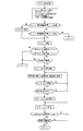
- FIG. 7 is a reset regeneration control flowchart of FIG. 6.
- FIG. 7 It is display explanatory drawing of reset reproduction
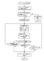
- FIG. 7 is a stationary regeneration control flowchart of FIG. 6. It is a display explanatory view of stationary regeneration control.
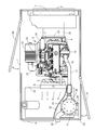
- FIGS. 1 to 10 are explanatory views of an engine generator as a stationary working machine showing the first embodiment.
- FIGS. 1 to 4 The structure of the stationary work machine according to the first embodiment will be described with reference to FIGS.
- a square box-shaped machine housing 2 is placed on the machine frame base 1.
- a diesel engine 3 is installed in the center inside the machine casing 2 on the upper surface of the machine frame base 1.
- a radiator 6 is arranged on the cooling fan 5 installation side on the front side of the diesel engine 3.
- a generator 18 described later is disposed on the back side of the diesel engine 3, and an operation panel unit 7 and an outside air intake port 8 are provided on the side wall of the machine housing 2 on the generator 18 installation side.
- a warm air discharge port 9 is provided on the side wall of the machine housing 2 on the radiator 6 installation side, and a fuel tank 10 for the diesel engine 3 is disposed on the upper surface of the machine frame base 1 on the radiator 6 installation side.
- an air cleaner 12 that removes and purifies external air is provided at the intake manifold 11 installation portion on the right side of the diesel engine 3, and an exhaust gas recirculation that recirculates part of the exhaust gas from the intake manifold 3 to each cylinder of the diesel engine 3.
- a circulation device (EGR) 13 is provided.
- An air cleaner 12 is connected to the intake manifold 11 via the exhaust gas recirculation device 13 and the intake pipe 14, and fresh air is supplied from the air cleaner 12 to the diesel engine 3.
- an exhaust throttle valve 16 is provided in the exhaust manifold 15 installation portion on the left side of the diesel engine 3.
- One end of the exhaust pipe 17 is connected to the exhaust manifold 15 via the exhaust throttle valve 16.
- the generator 18 as a working machine is attached to the flywheel housing 4 on the back side of the diesel engine 3.
- the drive shaft of the generator 18 is connected to the output shaft (not shown) of the diesel engine 3 via the PTO clutch 19 that is manually disconnected by the operator, and the generator 18 is driven by the diesel engine 3.
- the electric power of the generator 18 is configured to be supplied as a power source for an electric device or the like at a remote location using an electric cable.
- a cylindrical exhaust gas purification case (a DPF case for diesel particulates) 21 is provided as an exhaust gas purification device that removes particulate matter (soot) contained in the exhaust gas.
- a column body 22 is erected on the machine base 1, and the column body 22 is connected to a flange 23 outside the exhaust gas purification case 21 via a support arm body 24.
- An exhaust gas purification case 21 is installed in a vertically long position via a support column 22 above the fuel tank 10 inside the machine casing 2.
- the other end side of the exhaust pipe 17 is connected to the exhaust inlet pipe 25 on the upper end side of the exhaust gas purification case 21.
- An oxidation catalyst 26 and a soot filter 27 serving as a diesel particulate filter (DPF) for removing particulate matter in the exhaust gas of the diesel engine 3 are provided in the upper part and the intermediate part in the exhaust gas purification case 21, and the exhaust gas purification.
- a silencer 28 is provided in the lower part of the case 21. Exhaust gas of the diesel engine 3 supplied to the exhaust inlet pipe 25 is released to the outside of the machine casing 2 from the tail pipe 29 on the lower end side of the exhaust gas purification case 21 through the oxidation catalyst 26, the soot filter 27, and the silencer 28.
- the oxidation catalyst 26 and the soot filter 27 reduce carbon monoxide (CO), hydrocarbons (HC), particulate matter (PM), and nitrogen oxides (NOx) in the exhaust gas of the diesel engine 3. It is configured as follows.
- the first door 30 and the second door 31 are provided on the opposite side wall of the machine housing 2 so that they can be opened and closed, and the first door 30 and the second door 31 are opposed to the air cleaner 12 installation part and the exhaust gas purification case 21 installation part.
- the maintenance work of the air cleaner 12 or the exhaust gas purification case 21 is performed.
- An operator can be configured to be able to enter and leave the machine housing 2 from the first door 30 or the second door 31.
- a cooling air guide plate 32 that shields the side surface of the exhaust gas purification case 21 is provided between the radiator 6 and the warm air discharge port 9, and the warm air exhaust from the diesel engine 3 side through the radiator 6.
- the cooling air of the diesel engine 3 is guided toward the outlet 9 by the cooling air guide plate 32 to prevent the temperature of the exhaust gas purification case 21 from being lowered by the cooling air of the diesel engine 3.
- a remote controller 38 for remotely operating the diesel engine 3 is provided, and a remote controller controller 39 and an engine controller 40 formed by a microcomputer are provided.
- a rotation sensor 41 that detects the output shaft rotational speed of the diesel engine 3 is provided, and a differential pressure sensor 42 that detects an exhaust gas pressure difference before and after the soot filter 27, and a temperature sensor 43 that detects the exhaust gas temperature before and after the soot filter 27.
- the transmitter / receiver 48 to be connected is connected to the engine controller 40.
- a regeneration request lamp 51 that is turned on when particulate matter (PM) is deposited in the exhaust gas purification case 21 (soot filter 27) and a regeneration approval lamp 52 that is operated by an operator are provided.
- An interlock switch 58 that is turned on and off in conjunction with the engine controller 40 is connected.
- a liquid crystal display 61 for displaying information characters disposed on the remote controller 38, a start / stop switch 62 for starting or stopping the diesel engine 3, and a generator for remotely operating the power generation output unit 47.
- a remote switch 63, a fuel supply switch 64 that remotely controls the fuel supply of the diesel engine 3, and a transceiver 65 that is wirelessly connected to the engine controller 40 are connected to the remote controller controller 39.
- a regeneration request lamp 71 that is turned on when particulate matter (PM) is deposited in the exhaust gas purification case 21 (soot filter 27), and a regeneration approval lamp that is operated by the operator.
- the remote control controller 39 is connected with a regeneration approval switch 73 with 72, a regeneration prohibition switch 75 with a regeneration prohibition lamp 74 operated by an operator, and a notification buzzer 76 that sounds in conjunction with the lighting of the regeneration request lamp 71.
- the diesel engine 3 is operated to drive the generator 18, and the power of the generator 18 is used as a power source for a remote electric device or the like via an electric cable in construction work or civil engineering work.
- the rotational speed of the diesel engine 3 (output shaft) detected by the rotation sensor 41 and the exhaust gas differential pressure before and after the soot filter 27 detected by the differential pressure sensor 42 (exhaust gas in the exhaust gas purification case 21). Resistance) and the exhaust gas temperature in the exhaust gas purification case 21 detected by the temperature sensor 43 are read.
- the particulate matter accumulation amount (P Method PM deposition amount) is calculated (estimated).
- the particulate matter accumulation amount (C method PM deposition amount) in the case 21 is calculated (estimated).
- the PM accumulation map of the soot filter 27 is based on the detected value of the rotation sensor 41 (diesel engine 3 rpm), the detected value of the temperature sensor 43 (exhaust gas temperature), and the fuel injection amount of the fuel injection valve 44. , Created in advance and initially stored in the engine controller 40.
- assist regeneration PM combustion processing of the soot filter 27
- the assist regeneration is automatically controlled by opening and closing the exhaust throttle valve 16, and ends after a predetermined time has elapsed.
- an intake throttle valve may be provided in the intake manifold 11 and the exhaust gas temperature may be automatically controlled by opening or closing one or both of the exhaust throttle valve 16 and the intake throttle valve.
- the assist regeneration is executed while continuing the work such as the construction work or the civil engineering work with the output of the generator 18.
- reset regeneration of the soot filter 27
- the PM combustion processing injects fuel into the exhaust gas, raises the temperature of the exhaust gas to a predetermined temperature (TA) or more, and ends after a lapse of a predetermined time. "Is displayed on the liquid crystal display 61.
- the PM deposition amount in the P method is increased from a predetermined value (PA), or the PM deposition amount in the C method. Is larger than the predetermined value (CA), the characters “Standby regeneration standby” are displayed on the liquid crystal display 61.
- the reset regeneration is executed while continuing construction work or civil engineering work with the output of the generator 18, and the cumulative driving time (TB> TA) of the diesel engine 3 for each regeneration is different. At the same time, the reset playback execution time is longer than the assist playback execution time.
- the fuel injection valve 44 is automatically controlled by the regeneration request output of the engine controller 40 so that the rotational speed of the diesel engine 3 is set to an abnormal rotational speed lower than the normal rotational speed at which the generator 18 is operated.
- the change is made to notify the operator of the abnormality of the diesel engine 3 (soot filter 27).
- the operator detects the lighting of the regeneration request lamp 51, the sound of the alarm buzzer 56, the abnormal rotation of the diesel engine 3, or the character display of “stationary regeneration request” and “work stop” on the liquid crystal display 61.
- Interlock release for switching the lock switch 58 is performed by operating the on / off lever 57, and based on the character display “Please press and hold the regeneration approval switch” on the liquid crystal display 61, the regeneration approval switch 53 Is operated by the operator, stationary regeneration (PM combustion processing of the soot filter 27) is started, and the characters “regeneration operation start” are displayed on the liquid crystal display 61.
- the stationary regeneration is executed with the amount of particulate matter (PM) accumulated in the soot filter 27 as the accumulated amount.
- the stationary regeneration is terminated with the C method PM deposition amount lower than the predetermined value (CB) as the particulate matter (PM) deposition amount of the soot filter 27.
- a diesel engine 3 that drives a generator 18 as a working unit, and an exhaust gas purification case 21 as an exhaust gas purification device disposed in an exhaust path of the diesel engine 3.
- an engine controller 40 that controls the driving of the diesel engine 3 and is capable of performing regeneration control for burning and removing particulate matter in the exhaust gas purification case 21 (soot filter 27).
- the operator can recognize the abnormal accumulation of the particulate matter and regenerate the exhaust gas purification case 21 (the soot filter 27).
- the engine control operation of pressing the regeneration approval switch 73
- the worker is working at a place away from the installation place of the stationary work machine provided with the regeneration request lamp 51 or the buzzer 56, and the worker is alerted to the stationary work machine side.
- the operator can properly recognize the abnormal accumulation of the particulate matter by the alarm display of the remote controller 38, and the regeneration control of the exhaust gas purification case 21 (the soot filter 27) is not performed. Since the work is not continued in the state, maintenance at a repair shop (work for forcibly regenerating the exhaust gas purification case 21 or work for replacing the soot filter 27 of the exhaust gas purification case 21) is unnecessary. it can.
- the exhaust is determined based on the regeneration request signal of the engine controller 40.
- the engine control for regenerating the gas purification case 21 is configured to be started manually by the operator. Therefore, after the operator switches to the engine control state for regenerating the exhaust gas purification case 21 (soot filter 27), the operator makes a judgment and regenerates the exhaust gas purification case 21 (sot filter 27).
- the engine control can be started. It is possible to prevent the engine control for regenerating the exhaust gas purification case 21 (soot filter 27) from being started under a situation unintended by the operator, and the operation using the generator 18 or the compressor as a drive source is unexpected. Can be interrupted.
- the engine control for regeneration of the exhaust gas purification case 21 is automatically performed when the amount of particulate matter accumulated in the soot filter 27 falls. It is configured to completion. Therefore, the operator can easily recognize the regeneration request (alarm output) of the engine controller 40 and can appropriately execute the start operation of the regeneration control of the exhaust gas purification case 21, while the exhaust gas purification case 21 (soot filter) 27) When the amount of accumulated particulate matter falls, the regeneration control of the exhaust gas purification case 21 (soot filter 27) can be automatically terminated.
- the regeneration control of the exhaust gas purification case 21 can be started by the manual operation of the operator, and the regeneration control of the exhaust gas purification case 21 (soot filter 27) can be properly completed by automatic control.
- the regeneration control of the exhaust gas purification case 21 can be properly completed by automatic control.
Landscapes
- Engineering & Computer Science (AREA)
- Chemical & Material Sciences (AREA)
- Combustion & Propulsion (AREA)
- Mechanical Engineering (AREA)
- General Engineering & Computer Science (AREA)
- Processes For Solid Components From Exhaust (AREA)
- Control Of Vehicle Engines Or Engines For Specific Uses (AREA)
- Combined Controls Of Internal Combustion Engines (AREA)
Abstract
排気ガス浄化装置21を再生するためのエンジン制御(再生承認スイッチ73を押す操作)を早期に実行できるようにしたエンジン装置を提供することを課題としている。作業部18を駆動するエンジン3と、エンジン3の排気経路に配置した排気ガス浄化装置21と、エンジン3の駆動を制御するエンジンコントローラ40を備え、排気ガス浄化装置21内の粒子状物質を燃焼除去する再生制御を実行可能なエンジン装置において、エンジン3または作業部18を遠隔操作する遠隔操作器38を備え、排気ガス浄化装置21を再生するための前記エンジン制御が必要な状況のときに、エンジンコントローラ40の再生要求信号に基づき、前記排気ガス浄化装置21の再生要求が遠隔操作器38に警報表示されるように構成したものである。
Description
本願発明は、ディーゼルエンジンが搭載される建設機械(ブルドーザ、油圧ショベル、ローダー)または農業機械(トラクタ、コンバイン)または発電機またはコンプレッサなどのエンジン装置に係り、より詳しくは、排気ガス中に含まれた粒子状物質(すす)等を除去する排気ガス浄化装置が設置されたエンジン装置に関するものである。
従来から、ディーゼルエンジンの排気経路中に、排気ガス中に含まれた粒子状物質(すす)等を除去する排気ガス浄化装置を設け、排気ガス中に含まれた粒子状物質(すす)等を除去する技術が知られている(例えば特許文献1参照)。また、エンジン発電機を手元操作具にて遠隔操作する技術も知られている(例えば特許文献2参照)。
特許文献1のように、排気ガス中に含まれた粒子状物質(すす)等を排気ガス浄化装置のスートフィルタにて捕集する場合、機外に排出される排気ガス中の粒子状物質量を低減できるが、スートフィルタに粒子状物質が堆積して、再生要求ランプまたはブザーにて粒子状物質の異常堆積が警報されたとき、その再生要求ランプまたはブザーの警報を作業者が認識し、排気ガス浄化装置を再生するためのエンジン制御操作(再生承認スイッチを押す操作など)を行う必要がある。しかしながら、建築工事または土木工事などにおいて、再生要求ランプまたはブザーが配置された定置型作業機の設置場所から離れた場所で、電動機器などにて作業者が作業する場合、再生要求ランプまたはブザーの警報などを作業者が簡単に認識できないから、排気ガス浄化装置の再生制御が未実施の状態で作業が継続されやすく、修理専門店でのエンジンのメンテナンスが必要になる等の問題がある。
特に、建築工事に使用するエンジン発電機または土木工事に使用するエンジンコンプレッサなどのエンジン定置型作業機において、エンジンの設置場所から離れて作業するから、その作業機の再生要求ランプを作業者が常時監視できない。また、溶接機などの電動関連機材または掘削機などのエアー関連機材を使用する建築工事場所または土木工事場所の騒音などにて、前記ブザーの警報などを作業者が認識しにくい等の問題もある。
そこで、本願発明は、これらの現状を検討して改善を施したエンジン装置を提供しようとするものである。
請求項1の発明は、作業部を駆動するエンジンと、前記エンジンの排気経路に配置した排気ガス浄化装置と、前記エンジンの駆動を制御するエンジンコントローラを備え、前記排気ガス浄化装置内の粒子状物質を燃焼除去する再生制御を実行可能なエンジン装置において、前記エンジンまたは作業部を遠隔操作する遠隔操作器を備え、前記排気ガス浄化装置を再生するための前記エンジン制御が必要な状況のときに、前記エンジンコントローラの再生要求信号に基づき、前記排気ガス浄化装置の再生要求が遠隔操作器に警報表示されるように構成したものである。
請求項2の発明は、請求項1に記載したエンジン装置において、前記排気ガス浄化装置を再生するための前記エンジン制御が必要な状況のときに、前記エンジンコントローラの再生要求信号に基づき、前記排気ガス浄化装置を再生するための前記エンジン制御が作業者の手動操作にて開始されるように構成したものである。
請求項3の発明は、請求項1に記載したエンジン装置において、前記排気ガス浄化装置の粒子状物質の複数の堆積量検出値が、それぞれの堆積設定値のいずれかよりも増加したとき、そのいずれかの状態で所定時間が経過して、作業を中断した無負荷状態での前記排気ガス浄化装置の粒子状物質の燃焼処理が要求された場合、作業者の手動操作にて前記排気ガス浄化装置の再生のための前記エンジン制御を開始させる一方、前記エンジンの通算作動時間にて推定される粒子状物質の堆積量以下に、前記排気ガス浄化装置内の粒子状物質の堆積量が降下したときに、前記排気ガス浄化装置の再生のための前記エンジン制御を自動的に終了させるように構成したものである。
請求項1の発明によると、作業部を駆動するエンジンと、前記エンジンの排気経路に配置した排気ガス浄化装置と、前記エンジンの駆動を制御するエンジンコントローラを備え、前記排気ガス浄化装置内の粒子状物質を燃焼除去する再生制御を実行可能なエンジン装置において、前記エンジンまたは作業部を遠隔操作する遠隔操作器を備え、前記排気ガス浄化装置を再生するための前記エンジン制御が必要な状況のときに、前記エンジンコントローラの再生要求信号に基づき、前記排気ガス浄化装置の再生要求が遠隔操作器に警報表示されるように構成したものであるから、前記遠隔操作器の警報表示に伴い、作業中の作業者が前記エンジンの異変に気付き、作業者が前記排気ガス浄化装置(粒子状物質の堆積)の状況を速やかに確認できる。再生要求ランプまたはブザーにて粒子状物質の異常堆積が警報されたとき、その粒子状物質の異常堆積を作業者が認識でき、排気ガス浄化装置を再生するための前記エンジン制御(再生承認スイッチを押す操作)を早期に実行できる。例えば、建築工事または土木工事などにおいて、再生要求ランプまたはブザーを設けた定置型作業機の設置場所から離れた場所で作業者が作業していて、定置型作業機側の警報を作業者が容易に認識できなくても、前記遠隔操作器の警報表示にて粒子状物質の異常堆積を作業者が適正に認識でき、排気ガス浄化装置の再生制御が未実施の状態で作業が継続されることがないから、修理専門店でのメンテナンス(前記排気ガス浄化装置を強制的に再生する作業、前記排気ガス浄化装置のスートフィルタを交換する作業)などを不要にできる。
請求項2の発明によると、前記排気ガス浄化装置を再生するための前記エンジン制御が必要な状況のときに、前記エンジンコントローラの再生要求信号に基づき、前記排気ガス浄化装置を再生するための前記エンジン制御が作業者の手動操作にて開始されるように構成したものであるから、前記排気ガス浄化装置を再生するための前記エンジン制御状態に作業者が切換えてから、作業者が判断して、前記排気ガス浄化装置を再生するための前記エンジン制御を開始できる。作業者が意図しない状況下で、前記排気ガス浄化装置を再生するための前記エンジン制御が開始されるのを防止でき、発電機またはコンプレッサなどを駆動源とした作業が不意に中断されるのを阻止できる。
請求項3の発明によると、前記排気ガス浄化装置の粒子状物質の複数の堆積量検出値が、それぞれの堆積設定値のいずれかよりも増加したとき、そのいずれかの状態で所定時間が経過して、作業を中断した無負荷状態での前記排気ガス浄化装置の粒子状物質の燃焼処理が要求された場合、作業者の手動操作にて前記排気ガス浄化装置の再生のための前記エンジン制御を開始させる一方、前記エンジンの通算作動時間にて推定される粒子状物質の堆積量以下に、前記排気ガス浄化装置内の粒子状物質の堆積量が降下したときに、前記排気ガス浄化装置の再生のための前記エンジン制御を自動的に終了させるように構成したものであるから、前記エンジンコントローラの再生要求(警報出力)を作業者が簡単に認知でき、前記排気ガス浄化装置の再生制御の開始操作を適正に実行できるものでありながら、前記排気ガス浄化装置内の粒子状物質の堆積量が降下したときに、前記排気ガス浄化装置の再生制御を自動的に終了させることができる。即ち、作業者の手動操作にて、前記排気ガス浄化装置の再生制御を開始できると共に、前記排気ガス浄化装置の再生制御を自動制御にて適正に完了でき、前記再生制御の終了時期を作業者が誤認するのを防止でき、前記排気ガス浄化装置の再生作業性を向上できる。
以下、図1~図10を参照して、本願発明のエンジン装置の第1実施形態を図面に基づいて説明する。図1~図10は、第1実施形態を示す定置型作業機としてのエンジン発電機の説明図である。
図1~図4を参照して、第1実施形態の定置型作業機の構造を説明する。図1~図4に示す如く、機枠台1上に四角箱形の機筐2を載置する。機枠台1上面のうち機筐2の内部中央にディーゼルエンジン3を設置する。ディーゼルエンジン3前面側の冷却ファン5設置側にラジエータ6を配置する。ディーゼルエンジン3背面側に後述する発電機18が配置され、発電機18設置側の機筐2側壁に操作パネル部7と外気取入れ口部8を設けている。ラジエータ6設置側の機筐2側壁に暖気排出口部9を設けると共に、ラジエータ6設置側の機枠台1上面に、ディーゼルエンジン3用の燃料タンク10を配置している。
また、ディーゼルエンジン3の右側面側の吸気マニホールド11設置部に、外部空気を除塵・浄化するエアクリーナ12と、吸気マニホールド3からディーゼルエンジン3の各気筒に排気ガスの一部を還流させる排気ガス再循環装置(EGR)13を設ける。排気ガス再循環装置13と吸気管14を介して、吸気マニホールド11にエアクリーナ12を接続させ、エアクリーナ12からディーゼルエンジン3に新気を供給している。一方、ディーゼルエンジン3の左側面側の排気マニホールド15設置部に、排気スロットルバルブ16を設ける。排気スロットルバルブ16を介して排気マニホールド15に排気管17の一端側を接続させる。
ディーゼルエンジン3背面側のフライホイールハウジング4に作業機としての発電機18を取付けている。作業者が手動操作にて継断させるPTOクラッチ19を介して、ディーゼルエンジン3の出力軸(図示省略)に発電機18の駆動軸を連結させ、ディーゼルエンジン3にて発電機18を駆動する。発電機18の電力は、電気ケーブルにて遠隔場所の電動機器などの電源として供給するように構成している。なお、発電機18と同様に、ディーゼルエンジン3にて駆動するコンプレッサまたは油圧ポンプなどを設け、建築工事または土木工事などに使用する定置型作業機を構成することも可能である。
さらに、排気ガス中に含まれた粒子状物質(すす)等を除去する排気ガス浄化装置として、円筒状の排気ガス浄化ケース(ディーゼルパティキュレート用のDPFケース)21を備える。機枠台1上に支柱体22を立設させ、排気ガス浄化ケース21外側のフランジ23に支持アーム体24を介して支柱体22を連結させる。機筐2の内部のうち、燃料タンク10の上方に、支柱体22を介して縦長姿勢に排気ガス浄化ケース21を設置する。排気ガス浄化ケース21上端側の排気入口管25に排気管17の他端側を接続させる。
ディーゼルエンジン3の排気ガス中の粒子状物質を除去するディーゼルパティキュレートフィルタ(DPF)としての酸化触媒26及びスートフィルタ27を、排気ガス浄化ケース21内の上部及び中間部に設けると共に、排気ガス浄化ケース21内の下部に消音部28を設ける。排気入口管25に供給されたディーゼルエンジン3の排気ガスは、酸化触媒26、スートフィルタ27、消音部28を介して排気ガス浄化ケース21下端側のテールパイプ29から機筐2の外部に放出される。
即ち、ディーゼルエンジン3の各気筒から排気マニホールド15に排出された排気ガスが、排気ガス浄化ケース21等を経由して、機筐2の外部に放出されることにより、排気ガス浄化ケース21内部の酸化触媒26及びスートフィルタ27にて、ディーゼルエンジン3の排気ガス中の一酸化炭素(CO)や、炭化水素(HC)や、粒子状物質(PM)や、窒素酸化物質(NOx)を低減させるように構成している。
なお、機筐2の対向側壁に第1ドア30及び第2ドア31を開閉可能に設け、エアクリーナ12設置部及び排気ガス浄化ケース21設置部に第1ドア30及び第2ドア31を対向させて配置し、エアクリーナ12または排気ガス浄化ケース21のメンテナンス作業などを行う。第1ドア30または第2ドア31から作業者が機筐2内部に出入可能に構成できる。また、図3に示す如く、排気ガス浄化ケース21の側面を遮蔽する冷却風ガイド板32を、ラジエータ6と暖気排出口部9の間に設け、ラジエータ6を介してディーゼルエンジン3側から暖気排出口部9に向けて、ディーゼルエンジン3の冷却風を冷却風ガイド板32にて案内し、ディーゼルエンジン3の冷却風にて排気ガス浄化ケース21の温度が低下するのを防止している。
さらに、図1、図5~図10を参照して、排気ガス浄化ケース21内のスートフィルタ27の再生制御を説明する。図1、図5に示す如く、ディーゼルエンジン3を遠隔操作する遠隔操作器38を備えると共に、マイクロコンピュータにて形成する遠隔操作器コントローラ39とエンジンコントローラ40を備える。ディーゼルエンジン3の出力軸回転数を検出する回転センサ41と、スートフィルタ27の前後の排気ガス圧力差を検出する差圧センサ42と、スートフィルタ27の前後の排気ガス温度を検出する温度センサ43と、ディーゼルエンジン3のコモンレール式燃料噴射弁44と、ディーゼルエンジン3を始動するキースイッチ45及びスタータ46と、発電機18の出力をオンオフする発電出力部47と、遠隔操作器コントローラ39に無線接続させる送受信機48を、エンジンコントローラ40に接続させる。
また、図5に示す如く、排気ガス浄化ケース21(スートフィルタ27)内に粒子状物質(PM)が堆積したときに点灯させる再生要求ランプ51と、作業者が操作する再生承認ランプ52付きの再生承認スイッチ53と、作業者が操作する再生禁止ランプ54付きの再生禁止スイッチ55と、再生要求ランプ51の点灯と連動して鳴動させる報知ブザー56と、PTOクラッチ19の入切レバー57操作と連動してオンオフするインターロックスイッチ58を、エンジンコントローラ40に接続させる。
さらに、図5に示す如く、遠隔操作器38に配置する情報文字表示用の液晶表示器61と、ディーゼルエンジン3を起動または停止させる起動停止スイッチ62と、発電出力部47を遠隔操作する発電機遠隔スイッチ63と、ディーゼルエンジン3の燃料供給を遠隔制御する燃料供給スイッチ64と、エンジンコントローラ40に無線接続させる送受信機65を、遠隔操作器コントローラ39に接続させる。
また、図1、図5に示す如く、排気ガス浄化ケース21(スートフィルタ27)内に粒子状物質(PM)が堆積したときに点灯させる再生要求ランプ71と、作業者が操作する再生承認ランプ72付きの再生承認スイッチ73と、作業者が操作する再生禁止ランプ74付きの再生禁止スイッチ75と、再生要求ランプ71の点灯と連動して鳴動させる報知ブザー76を、遠隔操作器コントローラ39に接続させる。
図6のフローチャートに示す如く、ディーゼルエンジン3を作動させて、発電機18を駆動し、建築工事または土木工事などにおいて、電気ケーブルを介して遠隔場所の電動機器などに電源として発電機18の電力を供給するものであり、回転センサ41が検出するディーゼルエンジン3(出力軸)の回転数と、差圧センサ42が検出するスートフィルタ27前後の排気ガス差圧(排気ガス浄化ケース21内の排気抵抗)と、温度センサ43が検出する排気ガス浄化ケース21内の排気ガス温度を読み込む。
また、差圧センサ42(スートフィルタ27前後の排気ガス差圧)の検出値と、温度センサ43(排気ガス温度)の検出値に基づき、排気ガス浄化ケース21内の粒子状物質堆積量(P法PM堆積量)を演算(推定)する。一方、回転センサ41の検出値と、温度センサ43の検出値と、燃料噴射弁44の燃料噴射量と、スートフィルタ27のPM堆積マップと、ディーゼルエンジン3の累積駆動時間に基づき、排気ガス浄化ケース21内の粒子状物質堆積量(C法PM堆積量)を演算(推定)する。なお、前記スートフィルタ27のPM堆積マップは、回転センサ41(ディーゼルエンジン3回転数)の検出値と、温度センサ43(排気ガス温度)の検出値と、燃料噴射弁44の燃料噴射量にて、予め作成されて、エンジンコントローラ40に初期記憶されている。
そして、図6に示す如く、ディーゼルエンジン3の累積駆動時間が所定(TA)時間を経過したとき、アシスト再生(スートフィルタ27のPM燃焼処理)が自動的に実行される。アシスト再生(スートフィルタ27のPM燃焼処理)は、排気スロットルバルブ16の開閉にて排気ガス温度が自動制御され、所定時間経過後に終了する。なお、吸気マニホールド11に吸気スロットルバルブを設け、排気スロットルバルブ16または吸気スロットルバルブの一方または両方の開閉にて排気ガス温度を自動制御してもよい。なお、前記アシスト再生は、発電機18出力にて建築工事または土木工事などの作業を継続しながら実行される。
さらに、図6~図8に示す如く、ディーゼルエンジン3の累積駆動時間が所定時間(TB)を経過したとき、「リセット再生要求」の文字が液晶表示器61に表示されると共に、再生要求ランプ51,71が連続点灯し、再生承認ランプ52,72が点滅する。そして、再生承認スイッチ53,73が作業者にて手動操作されると、「リセット再生中」の文字が液晶表示器61に表示されると共に、リセット再生(スートフィルタ27のPM燃焼処理)が実行される。P法でのPM堆積量が所定値(PA)よりも増加していないとき、またはC法でのPM堆積量が所定値(CA)よりも増加していないとき、リセット再生(スートフィルタ27のPM燃焼処理)は、前記アシスト再生に加えて、排気ガス中に燃料を噴射させて、排気ガスの温度を所定温度(TA)以上に上昇させ、所定時間経過後に終了すると共に、「リセット再生完了」の文字が液晶表示器61に表示される。
一方、図7、図8に示す如く、前記リセット再生が開始されたときに、P法でのPM堆積量が所定値(PA)よりも増加している場合、またはC法でのPM堆積量が所定値(CA)よりも増加している場合、「ステーショナリ再生待機」の文字が液晶表示器61に表示される。なお、前記リセット再生は、発電機18出力にて建築工事または土木工事などの作業を継続しながら実行されるものであり、前記各再生のディーゼルエンジン3の累積駆動時間(TB>TA)が異なると共に、アシスト再生の実行時間よりもリセット再生の実行時間が長い。
さらに、図6、図9、図10に示す如く、P法でのPM堆積量が所定値(PA)よりも増加したとき、またはC法でのPM堆積量が所定値(CA)よりも増加したとき、そのいずれかの状態で所定時間が経過した場合、ステーショナリ再生(発電機18の出力を中断した無負荷状態でのスートフィルタ27のPM燃焼処理)が要求される。そのとき、エンジンコントローラ40の再生要求出力にて、再生要求ランプ51が点灯し、報知ブザー56が鳴動して、ステーショナリ再生要求出力を作業者に警報すると共に、「ステーショナリ再生要求」と「作業停止」の文字が液晶表示器61に表示される。
加えて、エンジンコントローラ40の再生要求出力にて、燃料噴射弁44を自動的に制御して、ディーゼルエンジン3の回転数を、発電機18を作動させる正常運転回転数よりも低い異常回転数に変更して、ディーゼルエンジン3(スートフィルタ27)の異常を作業者に報知する。再生要求ランプ51の点灯、または報知ブザー56の鳴動、またはディーゼルエンジン3の異常回転、または液晶表示器61の「ステーショナリ再生要求」と「作業停止」の文字表示を作業者が察知して、インターロックスイッチ58を切換えるインターロック解除(PTOクラッチ19切り)が入切レバー57操作にて行われ、液晶表示器61の文字表示「再生承認スイッチを長押ししてください」に基づき、再生承認スイッチ53が作業者にて操作されたとき、ステーショナリ再生(スートフィルタ27のPM燃焼処理)が開始されると共に、「再生運転開始」の文字が液晶表示器61に表示される。
作業者の手動操作(インターロック解除、再生承認スイッチ53操作)にてステーショナリ再生制御が実行されたときに、C法でのPM堆積量が所定値(CB)よりも低下していないとき(CA>CB)、所定時間が経過するまで、ステーショナリ再生制御が続行されると共に、「ステーショナリ再生中」と「作業部を停止/本機の操作を禁止中」の文字が液晶表示器61に表示される。。一方、C法でのPM堆積量が所定値(CB)よりも低下したときに、排気ガスの温度を所定温度(TB)以上に維持させ、所定時間が経過したとき、ステーショナリ再生制御が終了すると共に、「ステーショナリ再生完了」の文字が液晶表示器61に表示される。
再生禁止スイッチ55が作業者にて操作されていないとき、所定値(PA)よりも増加したP法PM堆積量、または所定値(CA)よりも増加したC法PM堆積量のいずれか多い側を、スートフィルタ27の粒子状物質(PM)堆積量として、ステーショナリ再生が実行される。また、所定値(CB)よりも低下したC法PM堆積量を、スートフィルタ27の粒子状物質(PM)堆積量として、ステーショナリ再生が終了される。
図1、図2、図5~図10に示す如く、作業部としての発電機18を駆動するディーゼルエンジン3と、ディーゼルエンジン3の排気経路に配置した排気ガス浄化装置としての排気ガス浄化ケース21と、ディーゼルエンジン3の駆動を制御するエンジンコントローラ40を備え、排気ガス浄化ケース21(スートフィルタ27)内の粒子状物質を燃焼除去する再生制御を実行可能なエンジン装置において、ディーゼルエンジン3または作業部18を遠隔操作する遠隔操作器38を備え、排気ガス浄化ケース21(スートフィルタ27)を再生するための前記エンジン制御が必要な状況のときに、前記エンジンコントローラ40の再生要求信号に基づき、排気ガス浄化ケース21の再生要求が遠隔操作器38に警報表示されるように構成している。
したがって、遠隔操作器38の警報表示に伴い、作業中の作業者がディーゼルエンジン3の異変に気付き、作業者が排気ガス浄化ケース21(粒子状物質の堆積)の状況を速やかに確認できる。再生要求ランプ71またはブザー76にて粒子状物質の異常堆積が警報されたとき、その粒子状物質の異常堆積を作業者が認識でき、排気ガス浄化ケース21(スートフィルタ27)を再生するための前記エンジン制御(再生承認スイッチ73を押す操作)を早期に実行できる。例えば、建築工事または土木工事などにおいて、再生要求ランプ51またはブザー56を設けた定置型作業機の設置場所から離れた場所で作業者が作業していて、定置型作業機側の警報を作業者が容易に認識できなくても、遠隔操作器38の警報表示にて粒子状物質の異常堆積を作業者が適正に認識でき、排気ガス浄化ケース21(スートフィルタ27)の再生制御が未実施の状態で作業が継続されることがないから、修理専門店でのメンテナンス(排気ガス浄化ケース21を強制的に再生する作業、排気ガス浄化ケース21のスートフィルタ27を交換する作業)などを不要にできる。
図5~図7、図9に示す如く、排気ガス浄化ケース21(スートフィルタ27)を再生するための前記エンジン制御が必要な状況のときに、前記エンジンコントローラ40の再生要求信号に基づき、排気ガス浄化ケース21(スートフィルタ27)を再生するための前記エンジン制御が作業者の手動操作にて開始されるように構成している。したがって、排気ガス浄化ケース21(スートフィルタ27)を再生するための前記エンジン制御状態に作業者が切換えてから、作業者が判断して、排気ガス浄化ケース21(スートフィルタ27)を再生するための前記エンジン制御を開始できる。作業者が意図しない状況下で、排気ガス浄化ケース21(スートフィルタ27)を再生するための前記エンジン制御が開始されるのを防止でき、発電機18またはコンプレッサなどを駆動源とした作業が不意に中断されるのを阻止できる。
図5~図7、図9に示す如く、排気ガス浄化ケース21(スートフィルタ27)の粒子状物質の複数の堆積量検出値が、それぞれの堆積設定値のいずれかよりも増加したとき、そのいずれかの状態で所定時間が経過して、作業を中断した無負荷状態での排気ガス浄化ケース21(スートフィルタ27)の粒子状物質の燃焼処理が要求された場合、作業者の手動操作にて排気ガス浄化ケース21(スートフィルタ27)の再生のための前記エンジン制御を開始させる一方、ディーゼルエンジン3の通算作動時間にて推定される粒子状物質の堆積量以下に、排気ガス浄化ケース21(スートフィルタ27)内の粒子状物質の堆積量が降下したときに、排気ガス浄化ケース21(スートフィルタ27)の再生のための前記エンジン制御を自動的に終了させるように構成している。したがって、エンジンコントローラ40の再生要求(警報出力)を作業者が簡単に認知でき、排気ガス浄化ケース21の再生制御の開始操作を適正に実行できるものでありながら、排気ガス浄化ケース21(スートフィルタ27)内の粒子状物質の堆積量が降下したときに、排気ガス浄化ケース21(スートフィルタ27)の再生制御を自動的に終了させることができる。即ち、作業者の手動操作にて、排気ガス浄化ケース21(スートフィルタ27)の再生制御を開始できると共に、排気ガス浄化ケース21(スートフィルタ27)の再生制御を自動制御にて適正に完了でき、前記再生制御の終了時期を作業者が誤認するのを防止でき、排気ガス浄化ケース21(スートフィルタ27)の再生作業性を向上できる。
3 ディーゼルエンジン
18 発電機(作業部)
21 排気ガス浄化ケース(排気ガス浄化装置)
38 遠隔操作器
40 エンジンコントローラ
18 発電機(作業部)
21 排気ガス浄化ケース(排気ガス浄化装置)
38 遠隔操作器
40 エンジンコントローラ
Claims (3)
- 作業部を駆動するエンジンと、前記エンジンの排気経路に配置した排気ガス浄化装置と、前記エンジンの駆動を制御するエンジンコントローラを備え、前記排気ガス浄化装置内の粒子状物質を燃焼除去する再生制御を実行可能なエンジン装置において、
前記エンジンまたは作業部を遠隔操作する遠隔操作器を備え、前記排気ガス浄化装置を再生するための前記エンジン制御が必要な状況のときに、前記エンジンコントローラの再生要求信号に基づき、前記排気ガス浄化装置の再生要求が遠隔操作器に警報表示されるように構成したことを特徴とするエンジン装置。 - 前記排気ガス浄化装置を再生するための前記エンジン制御が必要な状況のときに、前記エンジンコントローラの再生要求信号に基づき、前記排気ガス浄化装置を再生するための前記エンジン制御が作業者の手動操作にて開始されるように構成したことを特徴とする請求項1に記載のエンジン装置。
- 前記排気ガス浄化装置の粒子状物質の複数の堆積量検出値が、それぞれの堆積設定値のいずれかよりも増加したとき、そのいずれかの状態で所定時間が経過して、作業を中断した無負荷状態での前記排気ガス浄化装置の粒子状物質の燃焼処理が要求された場合、作業者の手動操作にて前記排気ガス浄化装置の再生のための前記エンジン制御を開始させる一方、前記エンジンの通算作動時間にて推定される粒子状物質の堆積量以下に、前記排気ガス浄化装置内の粒子状物質の堆積量が降下したときに、前記排気ガス浄化装置の再生のための前記エンジン制御を自動的に終了させるように構成したことを特徴とする請求項1に記載のエンジン装置。
Applications Claiming Priority (2)
| Application Number | Priority Date | Filing Date | Title |
|---|---|---|---|
| JP2013-141269 | 2013-07-05 | ||
| JP2013141269A JP2015014246A (ja) | 2013-07-05 | 2013-07-05 | エンジン装置 |
Publications (1)
| Publication Number | Publication Date |
|---|---|
| WO2015002140A1 true WO2015002140A1 (ja) | 2015-01-08 |
Family
ID=52143715
Family Applications (1)
| Application Number | Title | Priority Date | Filing Date |
|---|---|---|---|
| PCT/JP2014/067371 Ceased WO2015002140A1 (ja) | 2013-07-05 | 2014-06-30 | エンジン装置 |
Country Status (2)
| Country | Link |
|---|---|
| JP (1) | JP2015014246A (ja) |
| WO (1) | WO2015002140A1 (ja) |
Citations (3)
| Publication number | Priority date | Publication date | Assignee | Title |
|---|---|---|---|---|
| JP2009019534A (ja) * | 2007-07-10 | 2009-01-29 | Tadano Ltd | 作業用車両の排ガス浄化装置 |
| JP2010180853A (ja) * | 2009-02-09 | 2010-08-19 | Toyota Motor Corp | 内燃機関の排気浄化装置 |
| JP2011089479A (ja) * | 2009-10-22 | 2011-05-06 | Mitsubishi Fuso Truck & Bus Corp | Dpf再生制御装置 |
-
2013
- 2013-07-05 JP JP2013141269A patent/JP2015014246A/ja active Pending
-
2014
- 2014-06-30 WO PCT/JP2014/067371 patent/WO2015002140A1/ja not_active Ceased
Patent Citations (3)
| Publication number | Priority date | Publication date | Assignee | Title |
|---|---|---|---|---|
| JP2009019534A (ja) * | 2007-07-10 | 2009-01-29 | Tadano Ltd | 作業用車両の排ガス浄化装置 |
| JP2010180853A (ja) * | 2009-02-09 | 2010-08-19 | Toyota Motor Corp | 内燃機関の排気浄化装置 |
| JP2011089479A (ja) * | 2009-10-22 | 2011-05-06 | Mitsubishi Fuso Truck & Bus Corp | Dpf再生制御装置 |
Also Published As
| Publication number | Publication date |
|---|---|
| JP2015014246A (ja) | 2015-01-22 |
Similar Documents
| Publication | Publication Date | Title |
|---|---|---|
| JP5839784B2 (ja) | 排気ガス浄化システム | |
| CN104066940B (zh) | 工程机械 | |
| JP5388743B2 (ja) | 作業機の表示装置 | |
| JP5828579B2 (ja) | 作業機の排気ガス浄化システム | |
| CN103703232A (zh) | 作业机械的发动机控制系统 | |
| KR20230118845A (ko) | 작업 기계 | |
| JP2005299436A (ja) | フィルタ目詰り警告方法およびフィルタ目詰り解消方法 | |
| JP2011256767A (ja) | 作業機の排気ガス浄化システム | |
| JP5828578B2 (ja) | 排気ガス浄化システム | |
| WO2011138930A1 (ja) | 排気ガス浄化システム | |
| JP5307056B2 (ja) | エンジン装置 | |
| WO2015147230A1 (ja) | 作業車両 | |
| JP2014238091A (ja) | 排気ガス浄化システム | |
| JP5667781B2 (ja) | 作業機の排気ガス浄化システム | |
| JP2015183645A (ja) | エンジン装置 | |
| JP2015014246A (ja) | エンジン装置 | |
| JP6618494B2 (ja) | 建設機械 | |
| JP5622696B2 (ja) | 作業機 | |
| JP5667783B2 (ja) | 排気ガス浄化システム | |
| JP6207937B2 (ja) | ショベル及びショベルの管理装置 | |
| JP2014238050A (ja) | エンジン装置 | |
| JP5828577B2 (ja) | 排気ガス浄化システム | |
| JP5667784B2 (ja) | 排気ガス浄化システム | |
| JP2011231738A (ja) | 作業機の排気ガス浄化システム | |
| JP2016026281A (ja) | 作業機 |
Legal Events
| Date | Code | Title | Description |
|---|---|---|---|
| 121 | Ep: the epo has been informed by wipo that ep was designated in this application |
Ref document number: 14819759 Country of ref document: EP Kind code of ref document: A1 |
|
| NENP | Non-entry into the national phase |
Ref country code: DE |
|
| 122 | Ep: pct application non-entry in european phase |
Ref document number: 14819759 Country of ref document: EP Kind code of ref document: A1 |