WO2015001783A1 - データ送信方法、データ再生方法、データ送信装置およびデータ再生装置 - Google Patents
データ送信方法、データ再生方法、データ送信装置およびデータ再生装置 Download PDFInfo
- Publication number
- WO2015001783A1 WO2015001783A1 PCT/JP2014/003462 JP2014003462W WO2015001783A1 WO 2015001783 A1 WO2015001783 A1 WO 2015001783A1 JP 2014003462 W JP2014003462 W JP 2014003462W WO 2015001783 A1 WO2015001783 A1 WO 2015001783A1
- Authority
- WO
- WIPO (PCT)
- Prior art keywords
- time
- encoded data
- time information
- mpu
- unit
- Prior art date
- Legal status (The legal status is an assumption and is not a legal conclusion. Google has not performed a legal analysis and makes no representation as to the accuracy of the status listed.)
- Ceased
Links
Images


Classifications
-
- G—PHYSICS
- G11—INFORMATION STORAGE
- G11B—INFORMATION STORAGE BASED ON RELATIVE MOVEMENT BETWEEN RECORD CARRIER AND TRANSDUCER
- G11B27/00—Editing; Indexing; Addressing; Timing or synchronising; Monitoring; Measuring tape travel
- G11B27/10—Indexing; Addressing; Timing or synchronising; Measuring tape travel
-
- H—ELECTRICITY
- H04—ELECTRIC COMMUNICATION TECHNIQUE
- H04N—PICTORIAL COMMUNICATION, e.g. TELEVISION
- H04N21/00—Selective content distribution, e.g. interactive television or video on demand [VOD]
- H04N21/20—Servers specifically adapted for the distribution of content, e.g. VOD servers; Operations thereof
- H04N21/23—Processing of content or additional data; Elementary server operations; Server middleware
- H04N21/242—Synchronisation processes, e.g. processing of PCR [Programme Clock References]
-
- H—ELECTRICITY
- H04—ELECTRIC COMMUNICATION TECHNIQUE
- H04N—PICTORIAL COMMUNICATION, e.g. TELEVISION
- H04N21/00—Selective content distribution, e.g. interactive television or video on demand [VOD]
- H04N21/40—Client devices specifically adapted for the reception of or interaction with content, e.g. set-top-box [STB]; Operations thereof
- H04N21/43—Processing of content or additional data, e.g. demultiplexing additional data from a digital video stream; Elementary client operations, e.g. monitoring of home network or synchronising decoder's clock; Client middleware
- H04N21/4302—Content synchronisation processes, e.g. decoder synchronisation
-
- H—ELECTRICITY
- H04—ELECTRIC COMMUNICATION TECHNIQUE
- H04N—PICTORIAL COMMUNICATION, e.g. TELEVISION
- H04N21/00—Selective content distribution, e.g. interactive television or video on demand [VOD]
- H04N21/60—Network structure or processes for video distribution between server and client or between remote clients; Control signalling between clients, server and network components; Transmission of management data between server and client, e.g. sending from server to client commands for recording incoming content stream; Communication details between server and client
- H04N21/63—Control signaling related to video distribution between client, server and network components; Network processes for video distribution between server and clients or between remote clients, e.g. transmitting basic layer and enhancement layers over different transmission paths, setting up a peer-to-peer communication via Internet between remote STB's; Communication protocols; Addressing
- H04N21/643—Communication protocols
-
- H—ELECTRICITY
- H04—ELECTRIC COMMUNICATION TECHNIQUE
- H04N—PICTORIAL COMMUNICATION, e.g. TELEVISION
- H04N21/00—Selective content distribution, e.g. interactive television or video on demand [VOD]
- H04N21/80—Generation or processing of content or additional data by content creator independently of the distribution process; Content per se
- H04N21/83—Generation or processing of protective or descriptive data associated with content; Content structuring
- H04N21/845—Structuring of content, e.g. decomposing content into time segments
- H04N21/8456—Structuring of content, e.g. decomposing content into time segments by decomposing the content in the time domain, e.g. in time segments
-
- H—ELECTRICITY
- H04—ELECTRIC COMMUNICATION TECHNIQUE
- H04N—PICTORIAL COMMUNICATION, e.g. TELEVISION
- H04N21/00—Selective content distribution, e.g. interactive television or video on demand [VOD]
- H04N21/80—Generation or processing of content or additional data by content creator independently of the distribution process; Content per se
- H04N21/85—Assembly of content; Generation of multimedia applications
- H04N21/854—Content authoring
- H04N21/8547—Content authoring involving timestamps for synchronizing content
-
- H—ELECTRICITY
- H04—ELECTRIC COMMUNICATION TECHNIQUE
- H04L—TRANSMISSION OF DIGITAL INFORMATION, e.g. TELEGRAPHIC COMMUNICATION
- H04L5/00—Arrangements affording multiple use of the transmission path
- H04L5/14—Two-way operation using the same type of signal, i.e. duplex
- H04L5/143—Two-way operation using the same type of signal, i.e. duplex for modulated signals
-
- H—ELECTRICITY
- H04—ELECTRIC COMMUNICATION TECHNIQUE
- H04N—PICTORIAL COMMUNICATION, e.g. TELEVISION
- H04N21/00—Selective content distribution, e.g. interactive television or video on demand [VOD]
- H04N21/40—Client devices specifically adapted for the reception of or interaction with content, e.g. set-top-box [STB]; Operations thereof
- H04N21/43—Processing of content or additional data, e.g. demultiplexing additional data from a digital video stream; Elementary client operations, e.g. monitoring of home network or synchronising decoder's clock; Client middleware
Definitions
- This disclosure relates to a method for transmitting encoded data, a method for reproducing the data, and the like.
- MPEG-2 TS Motion Picture Experts Group-2 Transport Stream
- MMT MPEG as a new media transport method that assumes the use of various networks. Standardization of Media Transport is underway (see Non-Patent Document 1).
- MPEG media transport MMT
- a data transmission method includes a plurality of encoded data units each including a plurality of samples, reference time information indicating a reference time for setting the current time, and a head in the encoded data unit
- the start time information is a plurality of encoded data units that are presented or decoded after the start time information is transmitted among the generated encoded data units.
- the start time of each of the specific encoded data units is indicated, and each of the generated encoded data units is The time at which each of the first sample than in samples in No. data units are presented, or decoding, shown as a relative value with time of the other samples in the encoded data unit.
- the data transmission method of the present disclosure can be sufficiently applied to broadcasting.
- FIG. 1 is an explanatory diagram for explaining a problem of an assumed data transmission method.
- FIG. 2 is a block diagram of the data transmission apparatus in the present embodiment.
- FIG. 3 is a flowchart showing the operation of the data transmission apparatus according to the present embodiment.
- FIG. 4 is an explanatory diagram for explaining a data transmission method according to the present embodiment.
- FIG. 5 is a block diagram of the head time information generation unit in the present embodiment.
- FIG. 6 is a flowchart showing the operation of the start time information generation unit in the present embodiment.
- FIG. 7 is a block diagram of the above-described data reproducing apparatus in the present embodiment.
- FIG. 8 is a flowchart showing the operation of the data reproducing apparatus in the present embodiment.
- FIG. 9 is a block diagram of the head PTS determination unit in the present embodiment.
- FIG. 10 is a flowchart showing the operation of the leading PTS determination unit in the present embodiment.
- MMT which is a media transmission format that is being standardized by MPEG
- an MPU Media Processing Unit
- PTS Presentation Time Stamp
- DTS Decoding Time Stamp
- the data transmitting apparatus transmits the MPU start time information to the data reproducing apparatus.
- the start time information indicates, for example, a time (start PTS) at which presentation (or display) of the MPU is started.
- the head PTS is shown in the same format as the absolute time.
- a data reproducing apparatus that receives and reproduces MMT data requests MPU already stored in a server (data transmitting apparatus) or the like together with head time information when reproducing the data.
- the data transmitting apparatus transmits the MPU together with the head time information to the data reproducing apparatus.
- the data reproduction device reproduces the MPU so that the presentation of the MPU is started at the time of the first PTS indicated in the first time information.
- FIG. 1 is an explanatory diagram for explaining the problem of the data transmission method assumed from Non-Patent Document 1 and the like.
- the data transmission device transmits an asset that is a data string composed of a plurality of MPUs (MPU # 1, MPU # 2, MPU # 3,...) In MMT.
- the head PTSs of MPU # 1 and MPU # 2 are fixed.
- the data reproducing apparatus acquires the start time information at time T_get, and receives data of each MPU from MPU # 3 that starts processing first after time T_get.
- the head time information only indicates the head PTSs (PTSab_1, PTSab_2) of MPU # 1 and MPU # 2, and does not indicate the head PTS (PTSab_3) of MPU # 3. Therefore, the data reproducing apparatus cannot acquire the head PTS of MPU # 3.
- the data reproducing apparatus when the data reproducing apparatus starts to receive and reproduce the MPU distributed via the broadcast or the communication network in accordance with the user's acquisition request or the like, the data reproducing apparatus sets the head PTS of the received MPU. There is a problem that it cannot be acquired properly. That is, there is a problem that the start time of MPU decoding and display (output in the case of audio) cannot be determined. Further, if the head PTS cannot be acquired, for example, audio and video based on each other's PTS cannot be synchronized and reproduced.
- the assumed data transmission method and data reproduction method, and data transmission device and data reproduction device cannot be sufficiently applied to broadcasts that are required to be reproduced at a predetermined time. There is.
- the data reproducing apparatus since it was assumed that an MMT file (MP4 file) was transmitted, a sample PTS or a sample displayed or decoded first in an MPU (Media Processing Unit) of an asset configured according to the MMT DTS was known. For this reason, in the data reproducing apparatus, the first PTS and the first DTS in the MPU that starts reproduction can be acquired in advance.
- the data transmitting apparatus sequentially transmits the MMT data while generating the data, and the data reproducing apparatus reproduces the transmitted data
- the data reproducing apparatus is not limited to the top PTS of the MPU from which reproduction is started.
- the absolute time cannot be acquired in advance and the timing for starting playback cannot be determined. That is, there is a problem that it cannot be sufficiently applied to MMT data transmitted by live broadcasting or the like.
- a data transmission method includes a plurality of encoded data units each including a plurality of samples, and a reference time indicating a reference time for setting the current time
- the plurality of encodings generated by indicating start times of a plurality of specific encoded data units that are a plurality of encoded data units Each Tayunitto, indicate when each of the first sample except the sample in the coded data unit is presented or decoding, as a relative value with time of the other samples in the encoded data unit.
- the start time information includes, for example, the start time (for example, the start time) of each of a plurality of specific encoded data units (for example, a plurality of specific MPUs) to be presented or decoded after the start time information is transmitted PTS) is shown. Therefore, when receiving the start time information, the data reproducing apparatus can acquire the start time of each of the plurality of specific encoded data units that are presented or decoded after that time, that is, the appropriate start time. it can. As a result, the data reproduction device can appropriately start presenting or decoding a plurality of specific encoded data units from their start times. Therefore, it can be sufficiently applied to broadcasts that are required to be played back at a predetermined time.
- the data reproducing apparatus since the start time information indicates the start time of each of a plurality of specific encoded data units instead of only one, the data reproducing apparatus must receive any specific encoded data unit. Even in the case where it is not possible, if reception of another specific encoded data unit can be started, presentation or decoding of the specific encoded data unit can be started at an appropriate time.
- start time information may indicate at least the start time of an encoded data unit transmitted immediately after the start time information is transmitted among the plurality of generated encoded data units.
- the data reproducing apparatus can realize the presentation of the encoded data unit at an appropriate time or the start of decoding at an early stage.
- the head time information may be transmitted periodically.
- start time information may indicate the start times of the plurality of specific encoded data units whose presentation or decoding is started by the time when the start time information next to the start time information is transmitted.
- the plurality of start times indicated by the start time information are only the start times of the plurality of specific encoded data units whose presentation or decoding is started at a time close to the time at which the start time information is transmitted. Therefore, only the accurate start time can be indicated in the start time information.
- the data transmission method further includes: a propagation time from when data is transmitted to when it is received by the data reproduction device; and reception of an encoded data unit after the start time information is received by the data reproduction device. Including a calculation step of calculating a final reception time by adding a delay time until the start of the first time information to a time at which the start time information is transmitted.
- the start times of all the encoded data units that are presented or decoded between the time when the start time information is transmitted and the last reception time are encoded. It may be indicated as the first time.
- the start time information indicates a plurality of start times in consideration of the propagation time and the delay time
- presentation or decoding can be started after the start time information is received by the data reproducing device. It is possible to prevent that the first time of the encoded data unit is not shown in the first time information.
- a data reproduction method includes a plurality of encoded data units each including a plurality of samples, reference time information indicating a reference time for setting the current time, and the encoded data unit.
- the time point at which each of the plurality of non-leading samples is presented or decoded is indicated as a relative value to the time point of the other sample in the encoded data unit, and is indicated by the reference time information in the reproduction step. Indicated by a current time set according to a reference time, a start time of each of the plurality of specific encoded data units indicated by the start time information, and each of the received encoded data units.
- the previous plurality of samples are reproduced so that the plurality of samples included in the plurality of specific encoded data units are respectively presented or decoded at a timing according to the relative value of each of the plurality of non-leading samples. .
- the reproduction step when reproducing the first sample in the processing target encoded data unit that is any one of the plurality of specific encoded data units, the reference indicated by the reference time information
- the start sample is presented or decoded.
- the processing target non-leading sample that is any one of the plurality of non-leading samples in the processing target encoded data unit is played back
- the processing target non-leading sample is selected. A processing time to be presented or decoded is calculated, and when the current time has reached the calculated processing time, the processing target non-leading sample is presented or decoded.
- the processing target In the calculation of the processing time, the processing target The processing target encoded data unit indicated by the head time information, at least the relative value of the processing target non-head sample among the relative values of each of the plurality of non-head samples indicated by the encoded data unit.
- the processing time is calculated by adding to the first time.
- all samples (access units) included in a plurality of encoded data units can be presented or decoded at a predetermined time, and for broadcasts that are required to be reproduced at a predetermined time. Can be applied sufficiently.
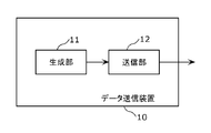
- FIG. 2 is a block diagram of the data transmission apparatus in the present embodiment.
- the data transmission device 10 in the present embodiment is a device that can be sufficiently applied to broadcasting, and includes a generation unit 11 and a transmission unit 12.
- the generation unit 11 presents or decodes a plurality of encoded data units each including a plurality of samples, reference time information indicating a reference time for setting the current time, and a leading sample in the encoded data unit. First time information indicating the first time, which is the time, is generated.
- the transmission unit 12 transmits the generated plurality of encoded data units, reference time information, and head time information.
- the start time information is a plurality of specific encoded data units that are a plurality of encoded data units that are presented or decoded after the start time information is transmitted among the plurality of encoded data units described above.
- the start time of each is shown.
- each of the plurality of encoded data units has a point in time at which each of the samples other than the first sample in the encoded data unit is presented or decoded as a time point of another sample in the encoded data unit. Shown as a relative value.
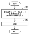
- FIG. 3 is a flowchart showing the operation of the data transmitting apparatus 10 in the present embodiment.
- the generation unit 11 generates a plurality of encoded data units, reference time information, and head time information (step S11).
- the transmission unit 12 transmits the generated plurality of encoded data units, reference time information, and head time information (step S12).
- the encoded data unit is an MPU in MMT
- the sample is an access unit.
- the reference time is a common time between the data transmitting apparatus 10 and the data reproducing apparatus that receives and reproduces data from the data transmitting apparatus 10, or is synchronized between the data transmitting apparatus 10 and the data reproducing apparatus. It is time for.
- the reference time is UTC (Coordinated Universal Time) or STC (System Time Clock).
- the beginning time information is presented or decoded with the MPU identification information (sequence number, etc.) and the leading access unit in the MPU. Shown in association with the first time, which is the time.
- the head sample (access unit) in the encoded data unit (MPU) is the head sample in the presentation order or the head sample in the decoding order. That is, if the start time indicated by the start time information is the time (start PTS) at which the start sample is presented, the start sample is the start sample in the presentation order. Further, if the head time indicated by the head time information is a time (head DTS) for decoding the head sample, the head sample is the head sample in the decoding order.
- the head time information includes a plurality of specific encoded data units (for example, presentation or decoding started after the head time information is transmitted).
- the start time (for example, start PTS) of a plurality of specific MPUs is shown. Therefore, when receiving the start time information, the data reproducing apparatus can acquire the start time of each of the plurality of specific encoded data units that are presented or decoded after that time, that is, the appropriate start time. it can.
- the data reproduction device can appropriately start presenting or decoding a plurality of specific encoded data units from their start times. Therefore, it can be sufficiently applied to broadcasts that are required to be played back at a predetermined time.
- the data reproducing apparatus since the start time information indicates the start time of each of a plurality of specific encoded data units instead of only one, the data reproducing apparatus must receive any specific encoded data unit. Even in the case where it is not possible, if reception of another specific encoded data unit can be started, presentation or decoding of the specific encoded data unit can be started at an appropriate time.
- an MPU, an access unit, and a head PTS will be described as specific examples of the encoded data unit, the sample, and the head time.
- the start time information in the present embodiment includes at least the start PTS of the MPU transmitted immediately after the transmission time of the start time information.
- the head PTS indicates the PTS of the sample that is the head in the presentation (display) order in the MPU in the same format as the absolute time.
- the absolute time is expressed by UTC (Coordinated Universal Time), and a value obtained by acquiring UTC by NTP (Network Time Protocol) is used.
- the absolute time is not limited to UTC, and any reference clock capable of expressing the absolute time, such as STC (System Time Clock) in MPEG-2 system, can be used.
- FIG. 4 is an explanatory diagram for explaining a data transmission method according to the present embodiment.
- the head time information d1 is stored at the head PTS of the MPU (MPU # 3, MPU # 4, MPU # 5) that is transmitted at the time T_send but not yet transmitted at the time T_send.
- the start time information d1 indicates the sequence number of MPU # 3 transmitted immediately after time T_send and the start PTS of MPU # 3 in association with each other.
- the sequence number of MPU # 4 and the MPU # The head PTS of # 4 is shown in association with it, and the sequence number of MPU # 5 and the head PTS of MPU # 5 are shown in association with each other.
- the number shown together with # on the right side of the MPU is the sequence number (identification information) of the MPU.
- the MPU of the sequence number indicated by the head time information d1 is the above-described specific encoded data unit.
- the data reproducing apparatus acquires the start time information d1 and starts reception from, for example, the data of MPU # 4.
- the data reproducing apparatus acquires the head PTS (PTSab_4) of MPU # 4 from the head time information d1, and starts presenting MPU # 4 when the current time becomes time PTSab_4.
- the data transmitting apparatus 10 transmits the start time information d1 for each asset.
- the start time information d1 may indicate the start DTS instead of the start PTS of the MPU, or may indicate both the start PTS and the start DTS.
- the leading DTS indicates the DTS of the sample leading in the decoding order in the MPU in the same format as the absolute time.
- the start time information d1 in the MMT MPU is described as an example, but the start time information d1 may indicate the start time of an encoded data unit other than the MPU.
- this embodiment is a PTS or DTS of an access unit (corresponding to a sample in MP4, MMT, or MPEG-DASH) such as MPEG-DASH (Dynamic Adaptive Streaming HTTP) Segment or MP4 Movie Fragment.
- MPEG-DASH Dynamic Adaptive Streaming HTTP
- MP4 Movie Fragment MP4 Movie Fragment.
- header information such as moov and mdat may not be transmitted, and only sample data constituting the MPU may be transmitted.
- the relative value from the PTS or DTS start time information d1 in the sample data in the MPU may be transmitted as information different from the MPU.
- the data transmission method according to the present embodiment can be applied to cases where content is received and reproduced by streaming (including multicast, broadcast, etc.) or downloading in a broadcast or communication network.
- the generation unit 11 of the data transmitting apparatus 10 stores at least the first PTS of a plurality of MPUs indicating the same time as the last reception time T_last or a time earlier than the last reception time T_last in the first time information d1.
- the final reception time T_last is defined as the time obtained by adding the maximum delay time Max_delay and the propagation time Trans_time to the transmission time T_send, as shown in (Equation 1) below.
- T_last T_send + Trans_time + Max_delay (Formula 1)
- T_send is the transmission time of the start time information d1
- Trans_time is the data propagation time in the transmission path (from when the data is transmitted until the data is received by the data reproducing apparatus) Time).
- Max_delay is the maximum value of the delay time from when the data reproduction apparatus receives the start time information d1 to when MPU reception is first started.
- the MPU is a random access unit (the head of the MPU is a random access point)
- the data reproducing apparatus when the data reproducing apparatus is able to acquire the head data of the MPU for the first time after receiving the head time information d1, the MPU starts from the MPU.
- the data including the MPU can be decoded.
- the generation unit 11 of the data transmission device 10 determines a random access unit such as an MPU from the delay time until reception of MPU data can be started after reception of the head time information d1.
- the maximum delay time Max_delay may be calculated by adding the maximum value of the reproduction time length of the file.
- the generation unit 11 of the data transmission apparatus 10 determines the maximum delay time based on the time from when the start time information d1 is received until the reception of the random access point data starts. Max_delay may be determined.
- the generation unit 11 of the data transmission device 10 When determining the transmission time T_send, the generation unit 11 of the data transmission device 10 does not use the exact transmission time of the start time information d1, but the estimated value of the transmission time or the time at which the start time information d1 is generated.
- the transmission time T_send may be determined.
- the generation unit 11 determines the final reception time T_last in consideration of the difference between the generation time and the actual transmission time. For example, the transmission unit 12 multiplexes the data packets when packetizing the head time information d1 and MPU (MMT packet, TS packet, RTP packet, etc.) and transmitting them. At this time, the packet of the head time information d1 and the packet of the MPU may not be multiplexed in ascending order of the time when the data included in these packets is generated. That is, a case may occur in which an MPU generated after the start time information d1 is transmitted before the start time information d1.
- MPU head time information
- the generation unit 11 may determine the final reception time T_last based on the amount of change in the transmission time caused by the change of order when packets are multiplexed.
- data multiplexing such as MPEG-DASH contents
- the generation unit 11 may periodically generate the start time information d1, and the transmission unit 12 may transmit the start time information d1 every time the start time information d1 is generated. Note that the plurality of head PTSs indicated by the head time information d1 transmitted sequentially are updated according to the transmission time T_send of the head time information d1.
- the generation unit 11 may compare the time calculated from (Equation 1) with (T_send + T) and determine the smaller value as T_last (if they are the same, any value is used). ).
- the generation unit 11 can determine the propagation time Trans_time according to a broadcasting system such as terrestrial broadcasting or satellite broadcasting.
- a broadcasting system such as terrestrial broadcasting or satellite broadcasting.
- the propagation time Trans_time may be ignored.
- the maximum delay time Max_delay can also be defined according to operational rules for broadcasting services.
- the propagation time Trans_time can be ignored because it is not necessary to consider the propagation time Trans_time.
- the generation unit 11 may set the propagation time Trans_time assuming the worst case, or after estimating the propagation time from the transmission server (data transmission device 10) to the data reproduction device, the generation time Trans_time is set. You may set adaptively.
- the start time information d1 and the MPU may be received by different channels (for example, the start time information d1 is received by HTTP, and the MPU is received by MMT protocol or RTP (Real-time Transport Protocol)).
- the data transmitting apparatus 10 may receive the MPU data transmitted before the transmission time of the head time information d1 after acquiring the head time information d1 (in FIG. After receiving the time information d1, MPU # 1 and MPU # 2 data are received). Therefore, the generation unit 11 may include the head PTS of the MPU transmitted before the transmission time T_send in the head time information d1.
- start time information d1 is transmitted by an MPEG-2 TS section or an MMT message in MMT
- an MPU having a start PTS indicating a time before the transmission time T_send is transmitted by the transmission time T_send. Will not be received after.
- a similar problem may occur when the start time information d1 is acquired from a transmission path other than broadcasting, such as via a communication network.
- the generation unit 11 calculates the final reception time T_last using the above (Equation 1), but adds a predetermined time length to the transmission time T_send without performing such calculation.
- the final reception time T_last may be determined.
- the generation unit 11 includes a start time information generation unit that generates start time information d1.
- FIG. 5 is a block diagram of the start time information generation unit in the present embodiment.
- the start time information generation unit 100 includes a start MPU determination unit 101, a start PTS acquisition unit 103, a determination unit 104, and an information generation unit 106.
- the start MPU determination unit 101 determines the MPU transmitted immediately after the transmission time T_send of the start time information d1 as the start MPU, and notifies the start PTS acquisition unit 103 of the identification information of the start MPU.
- the head PTS acquisition unit 103 acquires auxiliary information, and sequentially acquires the head PTS of each MPU after the start MPU indicated by the identification information notified from the start MPU determination unit 101 based on the auxiliary information. Then, every time the head PTS is acquired, the head PTS acquisition unit 103 notifies the determination unit 104 of the acquired head PTS.
- the determination unit 104 determines whether or not the top PTS notified from the top PTS acquisition unit 103 indicates before the last reception time T_last.
- the information generation unit 106 generates head time information d1 based on the determination result in the determination unit 104.
- FIG. 6 is a flowchart showing the operation of the start time information generation unit 100 in the present embodiment.
- the start MPU determination unit 101 determines a start MPU to be transmitted immediately after the transmission time T_send of the start time information d1.
- i is a sequence number (identification information).
- the start MPU determination unit 101 notifies the start PTS acquisition unit 103 of the identification information of the determined start MPU. Accordingly, when the head PTS acquisition unit 103 acquires the identification information from the start MPU determination unit 101, the head PTS of the start MPU (MPU (0)) indicated by the identification information is referred to auxiliary information as necessary. (Step S101).
- the determination unit 104 determines whether the first PTS indicates the time before the last reception time T_last (step S104).
- the propagation time Trans_time in (Expression 1) differs between, for example, a broadcast and a communication network, depending on a transmission path for transmitting MMT data. Therefore, the determination unit 104 may set a different value for the propagation time Trans_time according to a transmission path through which MMT data (MPU) is transmitted. For example, when two assets are transmitted via a broadcast and a communication network, the determination unit 104 sets a propagation time Trans_time for the broadcast and the communication network for each of the two assets.
- the determination unit 104 determines that the top PTS indicates the time before the last reception time T_last (Yes in step S104)
- the determination unit 104 notifies the determination result to the top PTS acquisition unit 103.
- the determination unit 104 determines that the first PTS does not indicate the time before the last reception time T_last (No in step S104)
- the determination unit 104 notifies the information generation unit 106 of the determination result.
- the information generation unit 106 generates start time information d1 storing the start PTS of each MPU from the 0th to the i-th (step S106).
- the head time information d1 generated in this way indicates the MPU identification information (for example, sequence number) and the head PTS of the MPU in association with each MPU from the 0th to the i-th.
- the information generation unit 106 reproduces not only the start PTS and flag of the start MPU described above but also the reproduction time of the start MPU and each subsequent MPU.
- the length is also stored in the start time information d1.
- step S103 shown in FIG. 6 will be described in detail.
- the method of acquiring the first PTS differs depending on the following three cases.
- the three cases are the first case where MPU (i-1) already exists, and the first case where MPU (i-1) can be generated from encoded data that does not exist but MPU (i-1) already exists.
- the second case and the third case where even the encoded data does not exist and the encoding process is necessary for the generation of MPU (i-1).
- the top PTS acquisition unit 103 adds the total playback time length of each sample constituting the MPU (i-1) to the PTS (i-1) that is the top PTS of the MPU (i-1). By adding, PTS (i) which is the head time of MPU (i) is acquired. At this time, the head PTS acquisition unit 103 acquires the above-described total reproduction time length by analyzing the MP4 header in MPU (i ⁇ 1). Note that the sum of the reproduction time lengths is handled as, for example, the above-described auxiliary information.
- the head PTS acquisition unit 103 determines one or more random access units constituting the MPU (i-1) from the encoded data. Then, the top PTS acquisition unit 103 adds the sum of the reproduction time lengths of the samples constituting the determined one or more random access units (for example, the auxiliary information described above) to PTS (i ⁇ 1). , PTS (i) is acquired.
- the random access unit corresponds to a sequence starting from an IDR picture in MPEG-4 AVC or HEVC (High Efficiency Video Coding), or a GOP of MPEG-2 Video.
- the head PTS acquisition unit 103 may determine a random access unit constituting the MPU using a playback time length preset for the MPU. For example, if the playback time length of the MPU is preset as 2 seconds and the playback time length of each random access unit is 1 second, the head PTS acquisition unit 103 determines two random access units constituting the MPU.
- the frame rate of the encoded data may change.
- the playback time length of the random access unit also changes. Therefore, the head PTS acquisition unit 103 may determine a random access unit constituting the MPU in consideration of this change.
- the head PTS acquisition unit 103 determines the playback time length of each access unit based on the sampling frequency. In addition, the head PTS acquisition unit 103 determines an access unit constituting the MPU (i-1) based on a preset reproduction time length of the MPU. Then, the top PTS acquisition unit 103 acquires PTS (i) by adding the sum of the reproduction time lengths of those access units to PTS (i ⁇ 1).
- the head PTS acquisition unit 103 determines the structure of the random access unit at the time of encoding (for example, the number of access units constituting the random access unit, the reference structure between the access units, etc.). Is set in advance. Then, the top PTS acquisition unit 103 calculates the playback time length of the random access unit based on a preset structure, and adds the playback time length to, for example, the PTS (i ⁇ 1) as the auxiliary information described above. To obtain PTS (i).
- an encoding unit (not shown) that generates encoded data by encoding the video data encodes the video data in accordance with a preset random access unit structure. Note that the encoding unit may or may not be provided in the data transmission device 10.
- the structure of the random access unit (structure A) set in advance may be different from the actual structure (structure B) of the encoded data generated by encoding by the encoding unit.
- the data transmitting apparatus 10 calculates a difference between the first PTS of the MPU corresponding to the structure A and the first PTS of the MPU corresponding to the structure B, and displays information (difference information) indicating the difference as a header of the MPU.
- Information (such as a box in 'moof') or a header of an MMT packet may be stored.
- the random access unit of structure A is composed of 15 access units
- the random access unit of structure B is composed of 18 access units
- the playback time length of the access unit is 20 msec.
- the data transmitting apparatus 10 sets the difference information indicating that the reproduction time length is longer by 60 msec than the estimated value by using the above-mentioned header To store.
- the data reproducing apparatus that has received such difference information corrects the head PTS indicated by the head time information d1 based on the difference information.
- the data reproducing apparatus also reflects the difference information on the head PTS indicated by the head time information d1 when calculating the head PTS of each MPU subsequent to the MPU corresponding to the corrected head PTS. For example, the data reproducing apparatus confirms the presence of the difference information, and if it exists, determines the first PTS that reflects the difference information.
- the information generation unit 106 may include information indicating whether or not the head PTS is a predicted value determined based on a preset structure of the random access unit in the head time information d1. This information may be included as information common to each head PTS in the head time information d1, or may be included as information set individually for each head PTS.
- the data transmitting apparatus 10 may also store information indicating the change in the reproduction time length in the above-described header or the like.
- the head PTS acquisition unit 103 uses the same method as in the second case described above based on the predetermined reproduction time length of the MPU. i) is determined. Note that when the sampling frequency is switched in the access unit constituting the MPU (i-1), the reproduction time length of the access unit changes. Therefore, the data transmitting apparatus 10 may also store information indicating the change in the reproduction time length in the above-described header or the like.
- step S101 in FIG. 6 when the top PTS acquisition unit 103 acquires the top PTS of the MPU (0), the top PTS acquisition unit 103 is also based on the information of the MPU immediately before the MPU (0).
- the head PTS of MPU (0) is acquired by performing the same process as the process of step S103 described above.
- FIG. 7 is a block diagram of the above-described data reproducing apparatus in the present embodiment.
- the data reproduction device 20 in the present embodiment is a device that can be sufficiently applied to broadcasting, and includes a reception unit 21 and a reproduction unit 22.
- the receiving unit 21 presents or decodes a plurality of encoded data units each including a plurality of samples, reference time information indicating a reference time for setting the current time, and the first sample in the encoded data unit.
- First time information d1 indicating the first time, which is the time, is received.
- the reproducing unit 22 reproduces a plurality of received encoded data units.
- the start time information d1 is a plurality of specific codes that are a plurality of encoded data units that are presented or decoded after the start time information d1 is received among the plurality of received encoded data units. Indicates the start time of the data unit.
- each of the plurality of received encoded data units indicates the time point at which each of a plurality of non-first samples, which are a plurality of samples other than the first sample in the encoded data unit, is presented or decoded. It is shown as a relative value with respect to the time points of other samples in the data unit.
- the playback unit 22 receives the current time set according to the reference time indicated by the reference time information, the start times of the plurality of specific encoded data units indicated by the start time information d1, and A plurality of samples included in the plurality of specific encoded data units are respectively presented or decoded at a timing according to the relative value of each of the plurality of non-leading samples indicated by each of the plurality of encoded data units. So that the multiple samples are played back.
- FIG. 8 is a flowchart showing the operation of the data reproducing apparatus 20 in the present embodiment.
- the receiving unit 21 receives a plurality of encoded data units, reference time information, and head time information d1 (step S21).
- the reproducing unit 22 reproduces the received plurality of encoded data units (step S22). That is, the reproduction unit 22 includes the current time set according to the reference time indicated by the reference time information, the respective start times of the plurality of specific encoded data units indicated by the start time information d1, and the received plurality of received times.
- a plurality of samples included in a plurality of specific encoded data units are respectively presented or decoded at a timing according to the relative value of each of the plurality of non-leading samples indicated by each of the encoded data units. The multiple samples are played back.
- the encoded data unit is an MPU in MMT
- the sample is an access unit.
- the reference time is a time that is common between the data transmission device 10 and the data reproduction device 20, or a time for synchronization between the data transmission device 10 and the data reproduction device 20.
- the reference time is UTC or STC.
- the start time information d1 indicates the identification information (sequence number, etc.) of the MPU and the top access unit in the MPU for each MPU that is presented or decoded after the start time information d1 is transmitted.
- the head time which is the time for decoding, is shown in association with it. Note that the head sample (access unit) in the encoded data unit (MPU) is the head sample in the presentation order or the head sample in the decoding order.
- all samples (access units) included in a plurality of encoded data units can be presented or decoded at a predetermined time
- the present invention can be sufficiently applied to broadcasts that are required to be reproduced at a predetermined time.
- the playback unit 22 includes a head PTS determination unit that determines the head PTS of each MPU to be presented or decoded based on the head time information d1.
- FIG. 9 is a block diagram of the head PTS determination unit in the present embodiment.
- the start PTS determination unit 200 includes a program information acquisition unit 201, a start time information acquisition unit 202, a start MPU acquisition unit 203, a start PTS determination unit 204, a first acquisition unit 205, and a second acquisition unit 206.
- the program information acquisition unit 201 acquires MMT program information (specifically, MPT) from the MMT package received by the reception unit 21.
- MPT MMT program information
- This program information is information transmitted from the data transmission device 10, and the program information acquisition unit 201 may acquire the program information via the reception unit 21 or without the reception unit 21. May be.
- the MMT program information is used to acquire assets such as identification information of each asset constituting the MMT package, access information of each asset (ID of MMT packet for transmitting asset data, URL for transmitting asset data, etc.). Necessary information).
- the start time information acquisition unit 202 acquires program information from the program information acquisition unit 201, and acquires the start time information d1 of the asset from the MMT package for each asset constituting the MMT package based on the program information. Then, the start time information acquisition unit 202 notifies the start MPU acquisition unit 203 that the start time information d1 has been acquired, and outputs the start time information d1 to the start PTS determination unit 204.
- the start time information d1 may be stored in an MMT message and transmitted, similarly to the program information.
- the start time information d1 may be stored as section data such as a PMT (Program Map Table) descriptor.
- PMT Program Map Table
- the start time information d1 may be stored as Segment information in MPD (Media Presentation Description).
- the start time information d1 may be transmitted separately.
- the program information and the start time information d1 may be acquired from a transmission path different from the MPU. In this case, for example, the data reproducing device 20 can obtain the MPU program information or the start time information d1 transmitted by broadcasting by accessing a server on the communication network prior to receiving the MPU. It is.
- the data transmitting apparatus 10 may determine the MPU corresponding to the head PTS stored in the head time information d1 in consideration of the difference.
- the first MPU acquisition unit 203 When the first MPU acquisition unit 203 is notified from the first time information acquisition unit 202 that the first time information d1 has been acquired, the first MPU data (first access unit) is received first after the first time information d1 is acquired. The sequence number of the MPU that has been acquired is acquired. Then, the head MPU acquisition unit 203 notifies the head PTS determination unit 204 of the sequence number.
- the start PTS determination unit 204 determines whether or not the start PTS of the MPU having the sequence number notified from the start MPU acquisition unit 203 is included in the start time information d1 output from the start time information acquisition unit 202.
- the first acquisition unit 205 acquires the first PTS of the MPU having the sequence number described above from the first time information d1, and acquires the first PTS.
- the first PTS is output.
- the second acquisition unit 206 calculates the first PTS of the MPU having the above sequence number based on the first time information d1. The calculated first PTS is output.
- initialization information at the time of decoding can be stored as sample data separately from headers such as moov and moof.
- decoding or presentation may be started from the first received sample without waiting for the head of the MPU.
- the header of the MMT packet indicates the sequence number of the MPU to which the sample data stored in the payload belongs and the number of the sample in decoding order in the MPU. Therefore, the DTS or PTS of the sample can be determined based on these pieces of information.
- FIG. 10 is a flowchart showing the operation of the head PTS determination unit 200 in the present embodiment.
- the program information acquisition unit 201 acquires program information (step S201).
- the start time information acquisition unit 202 acquires start time information d1 from the MMT package based on the program information (step S202).
- the head MPU acquisition unit 203 acquires the sequence number (SQN) of the MPU in which the head data of the MPU is first received after the head time information d1 is acquired (step S203).
- the head PTS determination unit 204 determines whether or not the head time information d1 includes the head PTS of the MPU (MPU (SQN)) identified by the acquired sequence number (SQN) (step S204). ). That is, the head PTS determination unit 204 determines whether or not the head PTS associated with the acquired sequence number (SQN) is included in the head time information d1.
- the first acquisition unit 205 determines that the first PTS included in the first time information d1. Is acquired (step S205).
- step S103 shown in FIG. 6 the head PTS is set on the assumption that video data or audio data is encoded based on a predetermined encoding operation as in the third case, and the actual PTS is set. If the encoding operation is different from the predetermined encoding operation, a difference occurs in the leading PTS. That is, a difference occurs between the leading PTS that is the predicted value included in the leading time information d1 and the leading PTS that is the actual value.
- the first acquisition unit 205 interprets information indicating whether the first PTS is a predicted value included in the MMT package, and determines that the first PTS is a predicted value. The difference information indicating the difference between the predicted value and the actual value is acquired. Then, the first acquisition unit 205 may acquire the first PTS in which the difference information is reflected by reflecting the difference information in the first PTS included in the first time information d1. Further, the first acquisition unit 205 may determine whether or not difference information exists, and if so, may reflect the difference information on the leading PTS included in the leading time information d1.
- the first acquisition unit 205 is included in the head time information d1 using the head PTS of the MPU subsequent to the MPU (SQN).
- the leading PTS may be corrected.
- the leading PTS corresponding to the MPU (MPU_pre) before decoding following the MPU (SQN) may be indicated in the leading time information repeatedly transmitted after the leading time information d1.
- the first acquisition unit 205 uses the head PTS corresponding to the MPU (MPU_pre) to calculate the head PTS of the MPU (SQN). decide.
- step S204 determines that the first PTS is not included in the first time information d1 (No in step S204).
- the second acquisition unit 206 determines that the MPU based on the first time information d1.
- the top PTS of (SQN) is calculated (step S206).
- step S206 will be described in detail.
- the second acquisition unit 206 When calculating the head PTS of the MPU (SQN), the second acquisition unit 206 first calculates the playback time length (DUR) of the MPU in which the head PTS is indicated in the head time information d1. Then, the second acquisition unit 206 may calculate the head PTS of the MPU (SQN) on the assumption that the playback time length of each MPU after that MPU is equal to the DUR. For example, it is assumed that the first PTS (PTSab_1, PTSab_2, PTSab_3) of each MPU (specific coded data unit) from MPU # 1 to MPU # 3 is stored in the head time information d1.
- DUR playback time length of the MPU in which the head PTS is indicated in the head time information d1.
- the second acquisition unit 206 may calculate the head PTS of the MPU (SQN) on the assumption that the playback time length of each MPU after that MPU is equal to the DUR. For example, it is assumed that the first P
- the data reproducing device 20 can start presentation (display) or decoding of the MPU (SQN) based on the estimated head PTS.
- the data reproducing device 20 may acquire other head time information subsequent to the head time information d1, and may acquire the head PTS of the MPU before decoding from the other head time information subsequent thereto.
- the data reproducing device 20 may set the PTS of the access unit that is first displayed in the MPU before decoding based on the leading PTS acquired from the other leading time information.
- the data reproducing device 20 sets the PTS of the access unit to the head PTS acquired from the subsequent head time information.
- the MPU (SQN) is decoded and presented (displayed) at a predetermined time in the data reproducing apparatus. You may start. For example, after buffering the encoded data of MPU (SQN), decoding of the first sample (access unit) in decoding order is completed, and the sample is presented at the earliest time that can be presented (displayed). Also at this time, the head PTS of the subsequent MPU may be adjusted based on other subsequent head time information.
- the second acquisition unit 206 performs the same method as described above.
- the head PTS of the MPU (SQN) can be calculated.
- the second acquisition unit 206 may acquire the start time information again when it is determined in step S204 that the start PTS is not included in the start time information d1.
- the data transmission device 10 periodically transmits head time information.
- the start time information of the MPU transmitted in the vicinity of the transmission time of the start time information is indicated by the start time information.
- the content has been updated. Therefore, the second acquisition unit 206 of the data reproducing device 20 transmits the time after the start time information d1 even if the start time information d1 does not include the start PTS of the MPU (SQN).
- the start PTS of the MPU can be acquired.
- the sequence number of MPU (SQN) is before the sequence number of MPU corresponding to the head PTS indicated by the head time information d1
- the head of MPU (SQN) is determined by the other head time information described above. PTS cannot be acquired. Therefore, in this case, the second acquisition unit 206 acquires the head PTS of the MPU (SQN) by assuming the playback time length of each MPU based on the head time information d1 as described above.
- the second acquisition unit 206 may separately acquire the start time information indicating the start PTS of the MPU (SQN) from a server or the like.
- the playback unit 22 of the data playback device 20 has the presentation order included in the MPU corresponding to the first PTS at the time indicated by the first PTS acquired by the first acquisition unit 205 or the second acquisition unit 206. Start presenting the first access unit. That is, when the reproducing unit 22 reproduces the head access unit in the processing target MPU that is one of the plurality of MPUs indicated by the head time information d1, the reference time indicated by the reference time information. When the current time set according to the above reaches the top PTS (head DTS) of the processing target MPU indicated by the head time information d1, the head access unit is presented (decoded).
- the MPU presents the time point at which each of the plurality of non-head access units, which are a plurality of access units other than the head access unit in the MPU, is presented (decoded) by the previous access unit in the MPU ( It is shown as a relative value (difference) with respect to the time of decoding.
- the playback unit 22 starts to present the nth access unit in the presentation order included in the MPU, first, the playback unit 22 starts from the first access unit (the access unit next to the top access unit) to the nth.
- the relative values of each access unit (each non-first access unit) up to the access unit are integrated.
- the playback unit 22 calculates the PTS of the nth access unit by adding the integration result of these relative values to the head PTS of the MPU. Then, the playback unit 22 starts presenting the nth access unit when the current time reaches the calculated PTS.
- the playback unit 22 when the playback unit 22 plays back a processing target non-head access unit that is any one of a plurality of non-head access units in the processing target MPU, the playback unit 22 first selects the processing target non-head access unit. A processing time to be presented (decoded) is calculated. Next, the playback unit 22 presents (decodes) the processing target non-first access unit when the current time reaches the calculated processing time. In the calculation of the processing time described above, the reproducing unit 22 uses at least the relative value of the processing target non-first access unit among the relative values of the plurality of non-first access units indicated by the processing target MPU, as the first time information The processing time is calculated by adding to the first PTS (first DTS) of the processing target MPU indicated by d1.
- the MMT data is sequentially transmitted while being generated, and even when the transmitted data is reproduced, by referring to the start time information,
- the head PTS of the received MPU can be acquired.
- the first PTS of the MPU is estimated based on the content of the first time information, or the first time information is The head PTS can be determined by repeatedly receiving.
- each component may be configured by dedicated hardware or may be realized by executing a software program suitable for each component.
- Each component may be realized by a program execution unit such as a CPU or a processor reading and executing a software program recorded on a recording medium such as a hard disk or a semiconductor memory.
- the software that implements the data transmission device 10 and the data reproduction device 20 according to the above-described embodiment is a program that causes a computer to execute the steps shown in FIG. 3 or FIG.
- the data of the MPU constituting the asset of the MMT package is transmitted in combination with transmission paths having different characteristics such as broadcasting and a communication network.
- transmission paths having different characteristics such as broadcasting and a communication network.
- only data received from either the transmission path of the broadcast or communication network is decoded and reproduced, and data received from both transmission paths of the broadcast and communication network is decoded and reproduced. .
- the data transmitting apparatus 10 separately stores and transmits the start time information corresponding to the MPU of the asset transmitted by broadcasting and the start time information corresponding to the MPU of the asset transmitted by the communication network. May be.
- the data reproduction device 20 can select and process the start time information according to the reproduction mode.
- the data transmission device 10 stores the start time information in the MMT in a table.
- the data transmitting apparatus 10 may store the head time information corresponding to the transmission paths of the broadcast and communication networks in separate tables. These tables are identified by identification information.
- the identification information is a table ID or the like.
- the data transmission device 10 may transmit a table corresponding to each of the broadcast and communication networks via the transmission paths of the broadcast and communication networks.
- the data transmission device 10 may transmit the tables for transmission through the corresponding transmission paths, such as transmitting the broadcast tables by broadcasting and transmitting the communication network tables through the communication network.
- the data transmitting apparatus 10 may signal the ID of the table to be used or may predefine it. In a case where broadcasting is used as a service entry, the data transmitting apparatus 10 may transmit both tables by broadcasting.
- the data transmitting apparatus 10 may store the start time information in an MMT descriptor or the like.
- the data transmission device 10 may be a table such as MPT (MMT Package Table) or MCIT (MMT Composition Information Table), that is, information on the acquisition method, decryption time or presentation time of asset data, or the display method of asset data, etc. May be stored and transmitted separately for each transmission path such as broadcast or communication network.
- the data transmitting apparatus 10 may transmit these tables on any one of the transmission paths, or transmit the broadcast table by broadcasting and communicate the communication network table on the communication network. You may transmit on the transmission line corresponding to.
- MMT MMT Package Table
- MCIT MMT Composition Information Table
- the data transmission method and the data reproduction method of the present disclosure transmit data using conventional MPEG-2 TS for broadcasting, and transmit data using MMT, MPEG-DASH, or the like in a communication channel (communication network).
- a communication channel communication network
- the present invention can also be applied to a case where data acquired through broadcasting and a communication network is handled in an integrated manner.
- head time information corresponding to MMT, MPEG-DASH, or the like transmitted on the communication path may be stored in TS section data or the like.
- a new descriptor can be defined, stored in the PMT, and transmitted.
- the communication server may determine the start time information independently of the broadcast and transmit it through the communication path.
- the data transmitting device 10 in the present embodiment packetizes and transmits the encoded data including the MPU and the start time information d1. .
- the data reproducing device 20 receives the packetized encoded data.
- the data reproduction device 20 in the present embodiment can start presenting the MPU at the correct time after the occurrence of the packet loss. That is, when the MPU packet is lost, the data reproducing device 20 may not be able to acquire the relative value (time difference) of the access units (non-first access units) included in the MPU. In such a case, the PTS of each access unit after that access unit included in the MPU cannot be determined.
- the data reproducing device 20 receives the head time information d1 indicating the head PTS of the MPU subsequent to the MPU in which the packet loss has occurred, thereby starting the presentation of the subsequent MPU from the head PTS. can do. As a result, the data reproduction device 20 can quickly recover the reproduction according to the correct time of the encoded data transmitted from the data transmission device 10.
- Each of the above devices is specifically a computer system including a microprocessor, a ROM, a RAM, a hard disk unit, a display unit, a keyboard, a mouse, and the like.
- a computer program is stored in the RAM or hard disk unit.
- Each device achieves its functions by the microprocessor operating according to the computer program.
- the computer program is configured by combining a plurality of instruction codes indicating instructions for the computer in order to achieve a predetermined function.
- a part or all of the components constituting each of the above devices may be configured by one system LSI (Large Scale Integration).
- the system LSI is an ultra-multifunctional LSI manufactured by integrating a plurality of components on a single chip, and specifically, a computer system including a microprocessor, ROM, RAM, and the like. .
- a computer program is stored in the RAM.
- the system LSI achieves its functions by the microprocessor operating according to the computer program.
- a part or all of the constituent elements constituting each of the above devices may be constituted by an IC card or a single module that can be attached to and detached from each device.
- the IC card or the module is a computer system including a microprocessor, a ROM, a RAM, and the like.
- the IC card or the module may include the super multifunctional LSI described above.
- the IC card or the module achieves its function by the microprocessor operating according to the computer program. This IC card or this module may have tamper resistance.
- the present disclosure may be the method described above. Further, the present invention may be a computer program that realizes these methods by a computer, or may be a digital signal composed of the computer program.
- the present disclosure also relates to a computer-readable recording medium such as a flexible disk, a hard disk, a CD-ROM, an MO, a DVD, a DVD-ROM, a DVD-RAM, a BD (Blu-ray ( (Registered trademark) Disc), or recorded in a semiconductor memory or the like.
- the digital signal may be recorded on these recording media.
- the computer program or the digital signal may be transmitted via an electric communication line, a wireless or wired communication line, a network represented by the Internet, a data broadcast, or the like.
- the present disclosure may be a computer system including a microprocessor and a memory, and the memory may store the computer program, and the microprocessor may operate according to the computer program.
- the program or the digital signal is recorded on the recording medium and transferred, or the program or the digital signal is transferred via the network or the like, and executed by another independent computer system. It is good.
- the data transmission method and the data reproduction method according to one or more aspects of the present disclosure have been described based on the embodiments, but the present disclosure is not limited to the embodiments. Unless it deviates from the gist of the present disclosure, one or more of the present disclosure may be applied to various modifications conceived by those skilled in the art in the present embodiment, or forms configured by combining components in different embodiments. It may be included within the scope of the embodiments.
- the data transmission method according to the present disclosure has an effect that it can be sufficiently applied to broadcasting, and can be applied to, for example, an apparatus or device that performs media transport such as video data and audio data.
Landscapes
- Engineering & Computer Science (AREA)
- Multimedia (AREA)
- Signal Processing (AREA)
- Computer Security & Cryptography (AREA)
- Two-Way Televisions, Distribution Of Moving Picture Or The Like (AREA)
- Synchronisation In Digital Transmission Systems (AREA)
- Compression Or Coding Systems Of Tv Signals (AREA)
Priority Applications (8)
| Application Number | Priority Date | Filing Date | Title |
|---|---|---|---|
| EP14820582.6A EP3018911B1 (en) | 2013-07-03 | 2014-06-30 | Data transmission method and data transmission device |
| CN201480025942.3A CN105191325B (zh) | 2013-07-03 | 2014-06-30 | 数据发送方法、数据再现方法、数据发送装置及数据再现装置 |
| US14/951,759 US9984726B2 (en) | 2013-07-03 | 2015-11-25 | Data transmission method, data playback method, data transmission device, and data playback device |
| US15/960,795 US10490225B2 (en) | 2013-07-03 | 2018-04-24 | Data transmission method, data playback method, data transmission device, and data playback device |
| US16/658,200 US10861500B2 (en) | 2013-07-03 | 2019-10-21 | Data transmission method, data playback method, data transmission device, and data playback device |
| US17/090,163 US11170818B2 (en) | 2013-07-03 | 2020-11-05 | Data transmission method, data playback method, data transmission device, and data playback device |
| US17/494,139 US11978487B2 (en) | 2013-07-03 | 2021-10-05 | Data transmission method, data playback method, data transmission device, and data playback device |
| US18/629,038 US12361974B2 (en) | 2013-07-03 | 2024-04-08 | Data transmission method, data playback method, data transmission device, and data playback device |
Applications Claiming Priority (4)
| Application Number | Priority Date | Filing Date | Title |
|---|---|---|---|
| US201361842480P | 2013-07-03 | 2013-07-03 | |
| US61/842,480 | 2013-07-03 | ||
| JP2014126553A JP2015015706A (ja) | 2013-07-03 | 2014-06-19 | データ送信方法、データ再生方法、データ送信装置およびデータ再生装置 |
| JP2014-126553 | 2014-06-19 |
Related Child Applications (1)
| Application Number | Title | Priority Date | Filing Date |
|---|---|---|---|
| US14/951,759 Continuation US9984726B2 (en) | 2013-07-03 | 2015-11-25 | Data transmission method, data playback method, data transmission device, and data playback device |
Publications (1)
| Publication Number | Publication Date |
|---|---|
| WO2015001783A1 true WO2015001783A1 (ja) | 2015-01-08 |
Family
ID=52437111
Family Applications (1)
| Application Number | Title | Priority Date | Filing Date |
|---|---|---|---|
| PCT/JP2014/003462 Ceased WO2015001783A1 (ja) | 2013-07-03 | 2014-06-30 | データ送信方法、データ再生方法、データ送信装置およびデータ再生装置 |
Country Status (5)
| Country | Link |
|---|---|
| US (6) | US9984726B2 (https=) |
| EP (1) | EP3018911B1 (https=) |
| JP (9) | JP2015015706A (https=) |
| CN (2) | CN105191325B (https=) |
| WO (1) | WO2015001783A1 (https=) |
Cited By (5)
| Publication number | Priority date | Publication date | Assignee | Title |
|---|---|---|---|---|
| WO2016125655A1 (ja) * | 2015-02-03 | 2016-08-11 | 日立マクセル株式会社 | 放送受信装置、放送受信方法及びコンテンツ出力方法 |
| WO2017014054A1 (ja) * | 2015-07-21 | 2017-01-26 | ソニー株式会社 | 送信装置、および送信方法、受信装置、および受信方法、並びにプログラム |
| CN107431845A (zh) * | 2015-03-31 | 2017-12-01 | 松下电器(美国)知识产权公司 | 发送方法、接收方法、发送装置以及接收装置 |
| CN113038188A (zh) * | 2015-03-31 | 2021-06-25 | 松下电器(美国)知识产权公司 | 发送方法、接收方法、发送装置以及接收装置 |
| US11405679B2 (en) | 2015-02-02 | 2022-08-02 | Maxell, Ltd. | Broadcast receiving apparatus, broadcast receiving method, and contents outputting method |
Families Citing this family (20)
| Publication number | Priority date | Publication date | Assignee | Title |
|---|---|---|---|---|
| US10779035B2 (en) * | 2014-01-09 | 2020-09-15 | Samsung Electronics Co., Ltd. | Method and apparatus of transmitting media data related information in multimedia transmission system |
| JP6681580B2 (ja) * | 2014-08-04 | 2020-04-15 | パナソニックIpマネジメント株式会社 | 送信方法、受信方法、送信装置及び受信装置 |
| JP6300114B2 (ja) * | 2014-08-06 | 2018-03-28 | パナソニックIpマネジメント株式会社 | 送信方法、受信方法、送信装置及び受信装置 |
| US9635407B2 (en) * | 2014-10-16 | 2017-04-25 | Samsung Electronics Co., Ltd. | Method and apparatus for bottleneck coordination to achieve QoE multiplexing gains |
| WO2016139909A1 (ja) * | 2015-03-02 | 2016-09-09 | 日本電気株式会社 | 復号装置、受信機器、送信機器、送受信システム、復号方法、および復号用プログラムが記憶された記憶媒体 |
| KR102473346B1 (ko) * | 2015-06-23 | 2022-12-05 | 삼성전자주식회사 | 디지털 방송 서비스 방법 및 장치 |
| JP6441247B2 (ja) * | 2015-10-01 | 2018-12-19 | マクセル株式会社 | 表示制御方法 |
| WO2017051808A1 (ja) | 2015-09-25 | 2017-03-30 | 日立マクセル株式会社 | 放送受信装置 |
| CN113660525A (zh) | 2015-09-25 | 2021-11-16 | 麦克赛尔株式会社 | 接收装置 |
| JP6611318B2 (ja) * | 2015-09-28 | 2019-11-27 | 東芝映像ソリューション株式会社 | 放送システム及び放送送受信方法 |
| CN110225370B (zh) * | 2016-01-18 | 2021-04-02 | 上海交通大学 | 一种多媒体内容个性化呈现的时间线控制方法 |
| EP3419297B1 (en) * | 2016-02-17 | 2021-07-21 | Samsung Electronics Co., Ltd. | Method and device for controlling the delivery type of mmt based multimedia service |
| CN109194971B (zh) * | 2018-08-27 | 2021-05-18 | 咪咕视讯科技有限公司 | 一种为多媒体文件的生成方法及装置 |
| JP6526892B2 (ja) * | 2018-09-03 | 2019-06-05 | 東芝映像ソリューション株式会社 | 放送送信装置及び放送送信方法 |
| JP6611388B2 (ja) * | 2018-09-03 | 2019-11-27 | 東芝映像ソリューション株式会社 | 放送受信装置及び放送受信方法 |
| JP6825075B2 (ja) * | 2019-12-27 | 2021-02-03 | 三菱電機株式会社 | 復号装置 |
| JP7003308B2 (ja) * | 2021-01-13 | 2022-01-20 | 三菱電機株式会社 | 復号装置 |
| US12294469B2 (en) * | 2022-05-12 | 2025-05-06 | Mellanox Technologies, Ltd | Boundary clock synchronized loop |
| US12524038B2 (en) | 2022-05-12 | 2026-01-13 | Mellanox Technologies, Ltd | Scalable boundary clock |
| US12289388B2 (en) | 2022-07-20 | 2025-04-29 | Mellanox Technologies, Ltd | Syntonization through physical layer of interconnects |
Family Cites Families (15)
| Publication number | Priority date | Publication date | Assignee | Title |
|---|---|---|---|---|
| GB2144257B (en) * | 1983-05-12 | 1986-09-17 | Victor Company Of Japan | Rotary recording medium |
| KR101777347B1 (ko) * | 2009-11-13 | 2017-09-11 | 삼성전자주식회사 | 부분화에 기초한 적응적인 스트리밍 방법 및 장치 |
| JP5489675B2 (ja) * | 2009-11-27 | 2014-05-14 | 三菱電機株式会社 | 映像情報再生方法及びシステム、並びに映像情報コンテンツ |
| KR101777348B1 (ko) * | 2010-02-23 | 2017-09-11 | 삼성전자주식회사 | 데이터 전송 방법 및 장치와 데이터 수신 방법 및 장치 |
| KR101476934B1 (ko) * | 2010-07-19 | 2014-12-30 | 엘지전자 주식회사 | 미디어 파일 송수신 방법 및 그를 이용한 송수신 장치 |
| KR101803970B1 (ko) * | 2011-03-16 | 2017-12-28 | 삼성전자주식회사 | 컨텐트를 구성하는 장치 및 방법 |
| KR101946861B1 (ko) * | 2011-09-21 | 2019-02-13 | 삼성전자주식회사 | 멀티미디어 방송 서비스의 미디어 데이터 동기화 방법 및 장치 |
| KR101885852B1 (ko) * | 2011-09-29 | 2018-08-08 | 삼성전자주식회사 | 컨텐트 전송 및 수신 방법 및 장치 |
| US9319721B2 (en) | 2011-10-13 | 2016-04-19 | Electronics And Telecommunications Research Institute | Method of configuring and transmitting an MMT transport packet |
| JP6126583B2 (ja) | 2012-03-28 | 2017-05-10 | 日本放送協会 | 符号化装置、復号装置及びこれらのプログラム |
| JP2013229690A (ja) * | 2012-04-24 | 2013-11-07 | Sharp Corp | 配信装置、配信方法、再生装置、再生方法、配信システム、プログラム、記録媒体およびメタデータ |
| KR101501344B1 (ko) * | 2012-05-02 | 2015-03-10 | 삼성전자주식회사 | 멀티미디어 서비스 송수신 방법 및 장치 |
| JP5641090B2 (ja) * | 2013-03-14 | 2014-12-17 | ソニー株式会社 | 送信装置、送信方法、受信装置および受信方法 |
| JP6323805B2 (ja) * | 2013-04-04 | 2018-05-16 | 日本放送協会 | 受信装置、送信装置、及び受信プログラム |
| KR102105567B1 (ko) * | 2014-01-09 | 2020-04-28 | 한국전자통신연구원 | Mmt 시그널링 메시지를 처리하는 장치 및 방법 |
-
2014
- 2014-06-19 JP JP2014126553A patent/JP2015015706A/ja active Pending
- 2014-06-30 CN CN201480025942.3A patent/CN105191325B/zh active Active
- 2014-06-30 CN CN201910445829.5A patent/CN110099289B/zh active Active
- 2014-06-30 WO PCT/JP2014/003462 patent/WO2015001783A1/ja not_active Ceased
- 2014-06-30 EP EP14820582.6A patent/EP3018911B1/en active Active
-
2015
- 2015-11-25 US US14/951,759 patent/US9984726B2/en active Active
-
2016
- 2016-12-08 JP JP2016238894A patent/JP6387075B2/ja active Active
-
2018
- 2018-04-24 US US15/960,795 patent/US10490225B2/en active Active
- 2018-08-10 JP JP2018151754A patent/JP6694022B2/ja active Active
-
2019
- 2019-10-21 US US16/658,200 patent/US10861500B2/en active Active
- 2019-12-26 JP JP2019237099A patent/JP6841896B2/ja active Active
-
2020
- 2020-11-05 US US17/090,163 patent/US11170818B2/en active Active
-
2021
- 2021-02-18 JP JP2021024346A patent/JP7036962B2/ja active Active
- 2021-10-05 US US17/494,139 patent/US11978487B2/en active Active
-
2022
- 2022-03-03 JP JP2022032321A patent/JP7260687B2/ja active Active
-
2023
- 2023-04-06 JP JP2023062320A patent/JP7506219B2/ja active Active
-
2024
- 2024-04-08 US US18/629,038 patent/US12361974B2/en active Active
- 2024-06-13 JP JP2024095671A patent/JP7707375B2/ja active Active
-
2025
- 2025-07-02 JP JP2025112675A patent/JP2025133854A/ja active Pending
Non-Patent Citations (2)
| Title |
|---|
| "CHO KO SEISAIDO TELEVISION HOSO SYSTEM NI KANSURU CHUKAN HOKOKU (TAJUKA HOSHIKI)", SUOMU, 3 December 2013 (2013-12-03), pages 33 - 34, XP055255518, Retrieved from the Internet <URL:http://www.soumu.go.jp/main_content/000270455.pdf> [retrieved on 20140918] * |
| AOKI ET AL.: "A Study on Media Transport Methods for Next-Generation Broadcasting Systems", ITE TECHNICAL REPORT, vol. 37, no. 9, 13 February 2013 (2013-02-13), pages 57 - 60, XP008179274 * |
Cited By (19)
| Publication number | Priority date | Publication date | Assignee | Title |
|---|---|---|---|---|
| US12267550B2 (en) | 2015-02-02 | 2025-04-01 | Maxell, Ltd. | Broadcast receiving apparatus, broadcast receiving method, and contents outputting method |
| US11871071B2 (en) | 2015-02-02 | 2024-01-09 | Maxell, Ltd. | Broadcast receiving apparatus, broadcast receiving method, and contents outputting method |
| US11405679B2 (en) | 2015-02-02 | 2022-08-02 | Maxell, Ltd. | Broadcast receiving apparatus, broadcast receiving method, and contents outputting method |
| US11184668B2 (en) | 2015-02-03 | 2021-11-23 | Maxell, Ltd. | Broadcast receiving apparatus, broadcast receiving method, and contents outputting method |
| US11962843B2 (en) | 2015-02-03 | 2024-04-16 | Maxell, Ltd. | Broadcast receiving apparatus, broadcast receiving method, and contents outputting method |
| WO2016125655A1 (ja) * | 2015-02-03 | 2016-08-11 | 日立マクセル株式会社 | 放送受信装置、放送受信方法及びコンテンツ出力方法 |
| US11695985B2 (en) | 2015-02-03 | 2023-07-04 | Maxell, Ltd. | Broadcast receiving apparatus, broadcast receiving method, and contents outputting method |
| US11477519B2 (en) | 2015-02-03 | 2022-10-18 | Maxell, Ltd. | Broadcast receiving apparatus, broadcast receiving method, and contents outputting method |
| US10547893B2 (en) | 2015-03-31 | 2020-01-28 | Panasonic Intellectual Property Corporation Of America | Receiving method, receiving device, and transmission and reception system |
| CN113038188A (zh) * | 2015-03-31 | 2021-06-25 | 松下电器(美国)知识产权公司 | 发送方法、接收方法、发送装置以及接收装置 |
| US11350154B2 (en) | 2015-03-31 | 2022-05-31 | Panasonic Intellectual Property Corporation Of America | Receiving method, receiving device, and transmission and reception system |
| CN107431845B (zh) * | 2015-03-31 | 2021-03-26 | 松下电器(美国)知识产权公司 | 发送方法、接收方法、发送装置以及接收装置 |
| US10945021B2 (en) | 2015-03-31 | 2021-03-09 | Panasonic Intellectual Property Corporation Of America | Receiving method, receiving device, and transmission and reception system |
| CN113038188B (zh) * | 2015-03-31 | 2023-06-06 | 松下电器(美国)知识产权公司 | 发送方法、接收方法、发送装置以及接收装置 |
| EP3280150A4 (en) * | 2015-03-31 | 2018-02-07 | Panasonic Intellectual Property Corporation of America | Transmission method, reception method, transmission device and reception device |
| CN107431845A (zh) * | 2015-03-31 | 2017-12-01 | 松下电器(美国)知识产权公司 | 发送方法、接收方法、发送装置以及接收装置 |
| US12382124B2 (en) | 2015-03-31 | 2025-08-05 | Panasonic Intellectual Property Corporation Of America | Receiving method, receiving device, and transmission and reception system |
| US10567852B2 (en) | 2015-07-21 | 2020-02-18 | Sony Corporation | Transmission device, transmission method, reception device, reception method, and program |
| WO2017014054A1 (ja) * | 2015-07-21 | 2017-01-26 | ソニー株式会社 | 送信装置、および送信方法、受信装置、および受信方法、並びにプログラム |
Also Published As
Similar Documents
| Publication | Publication Date | Title |
|---|---|---|
| JP7260687B2 (ja) | 送信方法および送信装置 | |
| JP7100175B2 (ja) | 送信方法及び送信装置 | |
| JP6625684B2 (ja) | 送信方法、受信方法、送信装置および受信装置 | |
| US10368115B2 (en) | Transmitting method, receiving method, transmitting device, and receiving device | |
| US12273580B2 (en) | Transmitting method, receiving method, transmitting device, and receiving device |
Legal Events
| Date | Code | Title | Description |
|---|---|---|---|
| WWE | Wipo information: entry into national phase |
Ref document number: 201480025942.3 Country of ref document: CN |
|
| 121 | Ep: the epo has been informed by wipo that ep was designated in this application |
Ref document number: 14820582 Country of ref document: EP Kind code of ref document: A1 |
|
| WWE | Wipo information: entry into national phase |
Ref document number: 2014820582 Country of ref document: EP |
|
| NENP | Non-entry into the national phase |
Ref country code: DE |