WO2014208641A1 - パンツ型着用物品及びその製造方法 - Google Patents
パンツ型着用物品及びその製造方法 Download PDFInfo
- Publication number
- WO2014208641A1 WO2014208641A1 PCT/JP2014/066926 JP2014066926W WO2014208641A1 WO 2014208641 A1 WO2014208641 A1 WO 2014208641A1 JP 2014066926 W JP2014066926 W JP 2014066926W WO 2014208641 A1 WO2014208641 A1 WO 2014208641A1
- Authority
- WO
- WIPO (PCT)
- Prior art keywords
- wearing article
- side seal
- pants
- type wearing
- exterior body
- Prior art date
Links
Images


Classifications
-
- A—HUMAN NECESSITIES
- A61—MEDICAL OR VETERINARY SCIENCE; HYGIENE
- A61F—FILTERS IMPLANTABLE INTO BLOOD VESSELS; PROSTHESES; DEVICES PROVIDING PATENCY TO, OR PREVENTING COLLAPSING OF, TUBULAR STRUCTURES OF THE BODY, e.g. STENTS; ORTHOPAEDIC, NURSING OR CONTRACEPTIVE DEVICES; FOMENTATION; TREATMENT OR PROTECTION OF EYES OR EARS; BANDAGES, DRESSINGS OR ABSORBENT PADS; FIRST-AID KITS
- A61F13/00—Bandages or dressings; Absorbent pads
- A61F13/15—Absorbent pads, e.g. sanitary towels, swabs or tampons for external or internal application to the body; Supporting or fastening means therefor; Tampon applicators
- A61F13/15577—Apparatus or processes for manufacturing
- A61F13/15707—Mechanical treatment, e.g. notching, twisting, compressing, shaping
- A61F13/15739—Sealing, e.g. involving cutting
-
- A—HUMAN NECESSITIES
- A61—MEDICAL OR VETERINARY SCIENCE; HYGIENE
- A61F—FILTERS IMPLANTABLE INTO BLOOD VESSELS; PROSTHESES; DEVICES PROVIDING PATENCY TO, OR PREVENTING COLLAPSING OF, TUBULAR STRUCTURES OF THE BODY, e.g. STENTS; ORTHOPAEDIC, NURSING OR CONTRACEPTIVE DEVICES; FOMENTATION; TREATMENT OR PROTECTION OF EYES OR EARS; BANDAGES, DRESSINGS OR ABSORBENT PADS; FIRST-AID KITS
- A61F13/00—Bandages or dressings; Absorbent pads
- A61F13/15—Absorbent pads, e.g. sanitary towels, swabs or tampons for external or internal application to the body; Supporting or fastening means therefor; Tampon applicators
- A61F13/15577—Apparatus or processes for manufacturing
- A61F13/15585—Apparatus or processes for manufacturing of babies' napkins, e.g. diapers
-
- A—HUMAN NECESSITIES
- A61—MEDICAL OR VETERINARY SCIENCE; HYGIENE
- A61F—FILTERS IMPLANTABLE INTO BLOOD VESSELS; PROSTHESES; DEVICES PROVIDING PATENCY TO, OR PREVENTING COLLAPSING OF, TUBULAR STRUCTURES OF THE BODY, e.g. STENTS; ORTHOPAEDIC, NURSING OR CONTRACEPTIVE DEVICES; FOMENTATION; TREATMENT OR PROTECTION OF EYES OR EARS; BANDAGES, DRESSINGS OR ABSORBENT PADS; FIRST-AID KITS
- A61F13/00—Bandages or dressings; Absorbent pads
- A61F13/15—Absorbent pads, e.g. sanitary towels, swabs or tampons for external or internal application to the body; Supporting or fastening means therefor; Tampon applicators
- A61F13/45—Absorbent pads, e.g. sanitary towels, swabs or tampons for external or internal application to the body; Supporting or fastening means therefor; Tampon applicators characterised by the shape
- A61F13/49—Absorbent articles specially adapted to be worn around the waist, e.g. diapers
- A61F13/496—Absorbent articles specially adapted to be worn around the waist, e.g. diapers in the form of pants or briefs
- A61F13/4963—Absorbent articles specially adapted to be worn around the waist, e.g. diapers in the form of pants or briefs characterized by the seam
-
- B—PERFORMING OPERATIONS; TRANSPORTING
- B29—WORKING OF PLASTICS; WORKING OF SUBSTANCES IN A PLASTIC STATE IN GENERAL
- B29C—SHAPING OR JOINING OF PLASTICS; SHAPING OF MATERIAL IN A PLASTIC STATE, NOT OTHERWISE PROVIDED FOR; AFTER-TREATMENT OF THE SHAPED PRODUCTS, e.g. REPAIRING
- B29C65/00—Joining or sealing of preformed parts, e.g. welding of plastics materials; Apparatus therefor
- B29C65/02—Joining or sealing of preformed parts, e.g. welding of plastics materials; Apparatus therefor by heating, with or without pressure
- B29C65/14—Joining or sealing of preformed parts, e.g. welding of plastics materials; Apparatus therefor by heating, with or without pressure using wave energy, i.e. electromagnetic radiation, or particle radiation
- B29C65/16—Laser beams
- B29C65/1629—Laser beams characterised by the way of heating the interface
- B29C65/1648—Laser beams characterised by the way of heating the interface radiating the edges of the parts to be joined
-
- B—PERFORMING OPERATIONS; TRANSPORTING
- B29—WORKING OF PLASTICS; WORKING OF SUBSTANCES IN A PLASTIC STATE IN GENERAL
- B29C—SHAPING OR JOINING OF PLASTICS; SHAPING OF MATERIAL IN A PLASTIC STATE, NOT OTHERWISE PROVIDED FOR; AFTER-TREATMENT OF THE SHAPED PRODUCTS, e.g. REPAIRING
- B29C65/00—Joining or sealing of preformed parts, e.g. welding of plastics materials; Apparatus therefor
- B29C65/02—Joining or sealing of preformed parts, e.g. welding of plastics materials; Apparatus therefor by heating, with or without pressure
- B29C65/14—Joining or sealing of preformed parts, e.g. welding of plastics materials; Apparatus therefor by heating, with or without pressure using wave energy, i.e. electromagnetic radiation, or particle radiation
- B29C65/16—Laser beams
- B29C65/1629—Laser beams characterised by the way of heating the interface
- B29C65/1654—Laser beams characterised by the way of heating the interface scanning at least one of the parts to be joined
- B29C65/1661—Laser beams characterised by the way of heating the interface scanning at least one of the parts to be joined scanning repeatedly, e.g. quasi-simultaneous laser welding
-
- B—PERFORMING OPERATIONS; TRANSPORTING
- B29—WORKING OF PLASTICS; WORKING OF SUBSTANCES IN A PLASTIC STATE IN GENERAL
- B29C—SHAPING OR JOINING OF PLASTICS; SHAPING OF MATERIAL IN A PLASTIC STATE, NOT OTHERWISE PROVIDED FOR; AFTER-TREATMENT OF THE SHAPED PRODUCTS, e.g. REPAIRING
- B29C65/00—Joining or sealing of preformed parts, e.g. welding of plastics materials; Apparatus therefor
- B29C65/02—Joining or sealing of preformed parts, e.g. welding of plastics materials; Apparatus therefor by heating, with or without pressure
- B29C65/14—Joining or sealing of preformed parts, e.g. welding of plastics materials; Apparatus therefor by heating, with or without pressure using wave energy, i.e. electromagnetic radiation, or particle radiation
- B29C65/16—Laser beams
- B29C65/1696—Laser beams making use of masks
-
- B—PERFORMING OPERATIONS; TRANSPORTING
- B29—WORKING OF PLASTICS; WORKING OF SUBSTANCES IN A PLASTIC STATE IN GENERAL
- B29C—SHAPING OR JOINING OF PLASTICS; SHAPING OF MATERIAL IN A PLASTIC STATE, NOT OTHERWISE PROVIDED FOR; AFTER-TREATMENT OF THE SHAPED PRODUCTS, e.g. REPAIRING
- B29C65/00—Joining or sealing of preformed parts, e.g. welding of plastics materials; Apparatus therefor
- B29C65/74—Joining or sealing of preformed parts, e.g. welding of plastics materials; Apparatus therefor by welding and severing, or by joining and severing, the severing being performed in the area to be joined, next to the area to be joined, in the joint area or next to the joint area
- B29C65/747—Joining or sealing of preformed parts, e.g. welding of plastics materials; Apparatus therefor by welding and severing, or by joining and severing, the severing being performed in the area to be joined, next to the area to be joined, in the joint area or next to the joint area using other than mechanical means
- B29C65/7473—Joining or sealing of preformed parts, e.g. welding of plastics materials; Apparatus therefor by welding and severing, or by joining and severing, the severing being performed in the area to be joined, next to the area to be joined, in the joint area or next to the joint area using other than mechanical means using radiation, e.g. laser, for simultaneously welding and severing
-
- B—PERFORMING OPERATIONS; TRANSPORTING
- B29—WORKING OF PLASTICS; WORKING OF SUBSTANCES IN A PLASTIC STATE IN GENERAL
- B29C—SHAPING OR JOINING OF PLASTICS; SHAPING OF MATERIAL IN A PLASTIC STATE, NOT OTHERWISE PROVIDED FOR; AFTER-TREATMENT OF THE SHAPED PRODUCTS, e.g. REPAIRING
- B29C65/00—Joining or sealing of preformed parts, e.g. welding of plastics materials; Apparatus therefor
- B29C65/76—Making non-permanent or releasable joints
-
- B—PERFORMING OPERATIONS; TRANSPORTING
- B29—WORKING OF PLASTICS; WORKING OF SUBSTANCES IN A PLASTIC STATE IN GENERAL
- B29C—SHAPING OR JOINING OF PLASTICS; SHAPING OF MATERIAL IN A PLASTIC STATE, NOT OTHERWISE PROVIDED FOR; AFTER-TREATMENT OF THE SHAPED PRODUCTS, e.g. REPAIRING
- B29C66/00—General aspects of processes or apparatus for joining preformed parts
- B29C66/01—General aspects dealing with the joint area or with the area to be joined
- B29C66/05—Particular design of joint configurations
- B29C66/10—Particular design of joint configurations particular design of the joint cross-sections
- B29C66/11—Joint cross-sections comprising a single joint-segment, i.e. one of the parts to be joined comprising a single joint-segment in the joint cross-section
- B29C66/112—Single lapped joints
- B29C66/1122—Single lap to lap joints, i.e. overlap joints
-
- B—PERFORMING OPERATIONS; TRANSPORTING
- B29—WORKING OF PLASTICS; WORKING OF SUBSTANCES IN A PLASTIC STATE IN GENERAL
- B29C—SHAPING OR JOINING OF PLASTICS; SHAPING OF MATERIAL IN A PLASTIC STATE, NOT OTHERWISE PROVIDED FOR; AFTER-TREATMENT OF THE SHAPED PRODUCTS, e.g. REPAIRING
- B29C66/00—General aspects of processes or apparatus for joining preformed parts
- B29C66/40—General aspects of joining substantially flat articles, e.g. plates, sheets or web-like materials; Making flat seams in tubular or hollow articles; Joining single elements to substantially flat surfaces
- B29C66/41—Joining substantially flat articles ; Making flat seams in tubular or hollow articles
- B29C66/43—Joining a relatively small portion of the surface of said articles
- B29C66/431—Joining the articles to themselves
-
- B—PERFORMING OPERATIONS; TRANSPORTING
- B29—WORKING OF PLASTICS; WORKING OF SUBSTANCES IN A PLASTIC STATE IN GENERAL
- B29C—SHAPING OR JOINING OF PLASTICS; SHAPING OF MATERIAL IN A PLASTIC STATE, NOT OTHERWISE PROVIDED FOR; AFTER-TREATMENT OF THE SHAPED PRODUCTS, e.g. REPAIRING
- B29C66/00—General aspects of processes or apparatus for joining preformed parts
- B29C66/70—General aspects of processes or apparatus for joining preformed parts characterised by the composition, physical properties or the structure of the material of the parts to be joined; Joining with non-plastics material
- B29C66/72—General aspects of processes or apparatus for joining preformed parts characterised by the composition, physical properties or the structure of the material of the parts to be joined; Joining with non-plastics material characterised by the structure of the material of the parts to be joined
- B29C66/723—General aspects of processes or apparatus for joining preformed parts characterised by the composition, physical properties or the structure of the material of the parts to be joined; Joining with non-plastics material characterised by the structure of the material of the parts to be joined being multi-layered
-
- B—PERFORMING OPERATIONS; TRANSPORTING
- B29—WORKING OF PLASTICS; WORKING OF SUBSTANCES IN A PLASTIC STATE IN GENERAL
- B29C—SHAPING OR JOINING OF PLASTICS; SHAPING OF MATERIAL IN A PLASTIC STATE, NOT OTHERWISE PROVIDED FOR; AFTER-TREATMENT OF THE SHAPED PRODUCTS, e.g. REPAIRING
- B29C66/00—General aspects of processes or apparatus for joining preformed parts
- B29C66/70—General aspects of processes or apparatus for joining preformed parts characterised by the composition, physical properties or the structure of the material of the parts to be joined; Joining with non-plastics material
- B29C66/72—General aspects of processes or apparatus for joining preformed parts characterised by the composition, physical properties or the structure of the material of the parts to be joined; Joining with non-plastics material characterised by the structure of the material of the parts to be joined
- B29C66/729—Textile or other fibrous material made from plastics
- B29C66/7294—Non woven mats, e.g. felt
- B29C66/72941—Non woven mats, e.g. felt coated
-
- B—PERFORMING OPERATIONS; TRANSPORTING
- B29—WORKING OF PLASTICS; WORKING OF SUBSTANCES IN A PLASTIC STATE IN GENERAL
- B29C—SHAPING OR JOINING OF PLASTICS; SHAPING OF MATERIAL IN A PLASTIC STATE, NOT OTHERWISE PROVIDED FOR; AFTER-TREATMENT OF THE SHAPED PRODUCTS, e.g. REPAIRING
- B29C66/00—General aspects of processes or apparatus for joining preformed parts
- B29C66/80—General aspects of machine operations or constructions and parts thereof
- B29C66/83—General aspects of machine operations or constructions and parts thereof characterised by the movement of the joining or pressing tools
- B29C66/834—General aspects of machine operations or constructions and parts thereof characterised by the movement of the joining or pressing tools moving with the parts to be joined
- B29C66/8341—Roller, cylinder or drum types; Band or belt types; Ball types
- B29C66/83431—Roller, cylinder or drum types; Band or belt types; Ball types rollers, cylinders or drums cooperating with bands or belts
- B29C66/83433—Roller, cylinder or drum types; Band or belt types; Ball types rollers, cylinders or drums cooperating with bands or belts the contact angle between said rollers, cylinders or drums and said bands or belts being a non-zero angle
-
- B—PERFORMING OPERATIONS; TRANSPORTING
- B29—WORKING OF PLASTICS; WORKING OF SUBSTANCES IN A PLASTIC STATE IN GENERAL
- B29C—SHAPING OR JOINING OF PLASTICS; SHAPING OF MATERIAL IN A PLASTIC STATE, NOT OTHERWISE PROVIDED FOR; AFTER-TREATMENT OF THE SHAPED PRODUCTS, e.g. REPAIRING
- B29C66/00—General aspects of processes or apparatus for joining preformed parts
- B29C66/80—General aspects of machine operations or constructions and parts thereof
- B29C66/83—General aspects of machine operations or constructions and parts thereof characterised by the movement of the joining or pressing tools
- B29C66/834—General aspects of machine operations or constructions and parts thereof characterised by the movement of the joining or pressing tools moving with the parts to be joined
- B29C66/8341—Roller, cylinder or drum types; Band or belt types; Ball types
- B29C66/83431—Roller, cylinder or drum types; Band or belt types; Ball types rollers, cylinders or drums cooperating with bands or belts
- B29C66/83435—Roller, cylinder or drum types; Band or belt types; Ball types rollers, cylinders or drums cooperating with bands or belts said rollers, cylinders or drums being hollow
-
- B—PERFORMING OPERATIONS; TRANSPORTING
- B29—WORKING OF PLASTICS; WORKING OF SUBSTANCES IN A PLASTIC STATE IN GENERAL
- B29C—SHAPING OR JOINING OF PLASTICS; SHAPING OF MATERIAL IN A PLASTIC STATE, NOT OTHERWISE PROVIDED FOR; AFTER-TREATMENT OF THE SHAPED PRODUCTS, e.g. REPAIRING
- B29C65/00—Joining or sealing of preformed parts, e.g. welding of plastics materials; Apparatus therefor
- B29C65/02—Joining or sealing of preformed parts, e.g. welding of plastics materials; Apparatus therefor by heating, with or without pressure
- B29C65/14—Joining or sealing of preformed parts, e.g. welding of plastics materials; Apparatus therefor by heating, with or without pressure using wave energy, i.e. electromagnetic radiation, or particle radiation
- B29C65/16—Laser beams
- B29C65/1603—Laser beams characterised by the type of electromagnetic radiation
- B29C65/1612—Infrared [IR] radiation, e.g. by infrared lasers
- B29C65/1619—Mid infrared radiation [MIR], e.g. by CO or CO2 lasers
-
- B—PERFORMING OPERATIONS; TRANSPORTING
- B29—WORKING OF PLASTICS; WORKING OF SUBSTANCES IN A PLASTIC STATE IN GENERAL
- B29C—SHAPING OR JOINING OF PLASTICS; SHAPING OF MATERIAL IN A PLASTIC STATE, NOT OTHERWISE PROVIDED FOR; AFTER-TREATMENT OF THE SHAPED PRODUCTS, e.g. REPAIRING
- B29C66/00—General aspects of processes or apparatus for joining preformed parts
- B29C66/01—General aspects dealing with the joint area or with the area to be joined
- B29C66/05—Particular design of joint configurations
- B29C66/10—Particular design of joint configurations particular design of the joint cross-sections
- B29C66/13—Single flanged joints; Fin-type joints; Single hem joints; Edge joints; Interpenetrating fingered joints; Other specific particular designs of joint cross-sections not provided for in groups B29C66/11 - B29C66/12
- B29C66/137—Beaded-edge joints or bead seals
-
- B—PERFORMING OPERATIONS; TRANSPORTING
- B29—WORKING OF PLASTICS; WORKING OF SUBSTANCES IN A PLASTIC STATE IN GENERAL
- B29C—SHAPING OR JOINING OF PLASTICS; SHAPING OF MATERIAL IN A PLASTIC STATE, NOT OTHERWISE PROVIDED FOR; AFTER-TREATMENT OF THE SHAPED PRODUCTS, e.g. REPAIRING
- B29C66/00—General aspects of processes or apparatus for joining preformed parts
- B29C66/70—General aspects of processes or apparatus for joining preformed parts characterised by the composition, physical properties or the structure of the material of the parts to be joined; Joining with non-plastics material
- B29C66/71—General aspects of processes or apparatus for joining preformed parts characterised by the composition, physical properties or the structure of the material of the parts to be joined; Joining with non-plastics material characterised by the composition of the plastics material of the parts to be joined
-
- B—PERFORMING OPERATIONS; TRANSPORTING
- B29—WORKING OF PLASTICS; WORKING OF SUBSTANCES IN A PLASTIC STATE IN GENERAL
- B29C—SHAPING OR JOINING OF PLASTICS; SHAPING OF MATERIAL IN A PLASTIC STATE, NOT OTHERWISE PROVIDED FOR; AFTER-TREATMENT OF THE SHAPED PRODUCTS, e.g. REPAIRING
- B29C66/00—General aspects of processes or apparatus for joining preformed parts
- B29C66/70—General aspects of processes or apparatus for joining preformed parts characterised by the composition, physical properties or the structure of the material of the parts to be joined; Joining with non-plastics material
- B29C66/73—General aspects of processes or apparatus for joining preformed parts characterised by the composition, physical properties or the structure of the material of the parts to be joined; Joining with non-plastics material characterised by the intensive physical properties of the material of the parts to be joined, by the optical properties of the material of the parts to be joined, by the extensive physical properties of the parts to be joined, by the state of the material of the parts to be joined or by the material of the parts to be joined being a thermoplastic or a thermoset
- B29C66/739—General aspects of processes or apparatus for joining preformed parts characterised by the composition, physical properties or the structure of the material of the parts to be joined; Joining with non-plastics material characterised by the intensive physical properties of the material of the parts to be joined, by the optical properties of the material of the parts to be joined, by the extensive physical properties of the parts to be joined, by the state of the material of the parts to be joined or by the material of the parts to be joined being a thermoplastic or a thermoset characterised by the material of the parts to be joined being a thermoplastic or a thermoset
- B29C66/7392—General aspects of processes or apparatus for joining preformed parts characterised by the composition, physical properties or the structure of the material of the parts to be joined; Joining with non-plastics material characterised by the intensive physical properties of the material of the parts to be joined, by the optical properties of the material of the parts to be joined, by the extensive physical properties of the parts to be joined, by the state of the material of the parts to be joined or by the material of the parts to be joined being a thermoplastic or a thermoset characterised by the material of the parts to be joined being a thermoplastic or a thermoset characterised by the material of at least one of the parts being a thermoplastic
- B29C66/73921—General aspects of processes or apparatus for joining preformed parts characterised by the composition, physical properties or the structure of the material of the parts to be joined; Joining with non-plastics material characterised by the intensive physical properties of the material of the parts to be joined, by the optical properties of the material of the parts to be joined, by the extensive physical properties of the parts to be joined, by the state of the material of the parts to be joined or by the material of the parts to be joined being a thermoplastic or a thermoset characterised by the material of the parts to be joined being a thermoplastic or a thermoset characterised by the material of at least one of the parts being a thermoplastic characterised by the materials of both parts being thermoplastics
-
- B—PERFORMING OPERATIONS; TRANSPORTING
- B29—WORKING OF PLASTICS; WORKING OF SUBSTANCES IN A PLASTIC STATE IN GENERAL
- B29L—INDEXING SCHEME ASSOCIATED WITH SUBCLASS B29C, RELATING TO PARTICULAR ARTICLES
- B29L2031/00—Other particular articles
- B29L2031/48—Wearing apparel
- B29L2031/4871—Underwear
- B29L2031/4878—Diapers, napkins
Definitions
- the present invention relates to a pants-type wearing article having a side seal portion.
- a conventional pant-type wearing article includes an absorbent main body and an exterior body that forms the outer surface of the wearing article, and both side edges of the exterior body in the front body and both side edges of the exterior body in the back body are joined together.
- a pants-type disposable diaper in which a side seal portion is formed is known.
- Patent Document 1 discloses that the side seal part has three stages from the viewpoint of coexistence of sufficient fusion strength that does not come off during wearing of the diaper and improvement of tearability. It is described that the fusion strength coexists.
- a heat roll device has been widely used for joining stacked sheets.
- the side seal portion is heated as described later. It is formed using a roll device.
- a method of welding using laser light is also known.
- Patent Document 2 a sheet laminate in which a plurality of sheets are stacked is deformed into a shape along the peripheral surface of a rotary roll having a laser light transmitting portion on the peripheral surface, and the sheet is conveyed. A method of irradiating the laminated body with laser light from the inside of the rotary roll to fuse the sheets in the laminated sheet is described.
- ⁇ Pants-type disposable diapers are usually manufactured through the following processes. That is, a diaper continuous body in which a plurality of diapers are arranged in one direction (conveying direction) is manufactured, and the front body side exterior body and the back body side of the diaper continuous body are overlapped with each other at a site where the side seal portion is to be formed. After the exterior body is joined by a joining means such as a heat roll device, the joint part is cut by a cutting means such as a cutter, thereby being divided into individual diapers.
- the side seal part of the conventional pants-type disposable diaper manufactured in this way is formed by overlapping the side edge part of the front body and the side edge part of the back body in the shape of a palm, and the top of the palm-shaped portion is Since it protrudes outward from the diaper than the part, it can be easily recognized visually.
- the palm-shaped side seal part obtained through the manufacturing process described above is relatively hard because it has a wide bonding width between exterior bodies and the exterior bodies are strongly pressurized during joining. There is room for improvement in terms of feeling and feel on the outer surface.
- the joint width between the exterior bodies in the side seal part is narrowed, the joint part between the edge of the exterior body in the front body and the edge of the exterior body in the back body extends with substantially the same width in the longitudinal direction of the side seal part. Therefore, it is difficult to change the fusion strength in the longitudinal direction of the side seal portion.
- the fusion strength is increased over the entire length of the side seal portion, and it becomes difficult to tear the side seal portion after use of the diaper, or the fusion strength is decreased over the entire length of the side seal portion.
- unintended side seal portions are easily peeled off during wearing.
- Patent Documents 1 and 2 do not describe the ease of tearing or the feeling of tearing or the method of the side seal part in which the joint width between the exterior bodies is narrowed.
- the present invention includes an exterior body that forms an outer surface of a worn article, and a pair of side seal portions, a waist opening, and both side edges of the exterior body in the front body and both side edges of the exterior body in the back body are joined together
- a pants-type wearing article in which a pair of leg openings is formed is provided.
- the side seal part is a continuous linear fusion in which the edge of the exterior body in the front body and the edge of the exterior body in the back body extend in the longitudinal direction of the side seal part.
- the seal edge part is formed over the entire length of the side seal part, and has a strength of fusion strength in the longitudinal direction.
- this invention provides the manufacturing method of the said underpants type wearing article.
- the first method of the present invention is in a pressurized state, a polymerization pressurizing step in which a site where a side seal portion is to be formed in a belt-shaped exterior body in a state where the front body side and the back body side are overlapped is in a pressurized state.
- a side seal part forming step of forming the side seal part by fusing the cut edges of the laminated outer package.
- the width of the light passage portion is fused to the seal edge portion using a support member that changes discontinuously or continuously in the longitudinal direction of the light passage portion. Forms the strength of wearing strength.
- this invention provides the manufacturing method of the said underpants type wearing article.
- the second method of the present invention is a polymerization pressurizing step for pressing the formation planned site of the side seal part in the belt-shaped exterior body in a state where the front body side and the back body side are overlapped, While cutting the exterior body by irradiating a laser beam through a light passage portion extending in a direction intersecting the transport direction of the exterior body to the formation planned site of the side seal portion in a pressurized state And a side seal portion forming step of forming the side seal portion by fusing the cut edge portions of the laminated exterior body produced by the division.
- a protrusion projecting toward the exterior body is provided in the vicinity of the light passage portion on the outer surface in contact with the exterior body, and the projecting height or width of the projecting portion is Using a support member that changes discontinuously or continuously along the longitudinal direction of the light passage portion, the strength of the fusion strength is formed on the seal edge portion.
- this invention provides the manufacturing method of the said underpants type wearing article.
- the third method of the present invention is in a pressurized state, a polymerization pressurizing step in which the site where the side seal portion is to be formed in the belt-shaped exterior body in a state where the front body side and the back body side are overlapped is in a pressurized state.
- a side seal part forming step of forming the side seal part by fusing the cut edges of the laminated outer package.
- the strength of the fusion strength is formed at the seal edge portion by changing the output of laser light to be irradiated or the scanning speed.
- FIG. 1 is a schematic perspective view which shows an example of the manufacturing method of the underpants type disposable diaper using the laser type
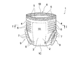
- FIG. 2 is a perspective view schematically showing a pants-type disposable diaper of the basic technology manufactured by carrying out the manufacturing method shown in FIG.
- FIG. 3 is a cross-sectional view schematically showing a cross section taken along line II of FIG.
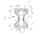
- FIG. 4 is a plan view schematically showing a developed and extended state of the diaper shown in FIG.
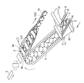
- FIG. 5 is a perspective view schematically showing a manufacturing process of the diaper continuous body shown in FIG. 1.
- FIGS. 7 (a) and 7 (c) are diagrams schematically showing a state where the diaper continuous body is introduced into the laser-type bonding apparatus shown in FIG. 1 in a plane
- FIG. FIG. 6B is a cross-sectional view taken along the line II-II of FIG. 6A.
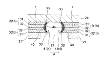
- FIGS. 7 (a) to 7 (c) show the side seal portion (seal edge) at the same time that the continuous diaper (strip-shaped exterior body) is cut using the laser type bonding apparatus shown in FIG. It is explanatory drawing explaining a mode that it forms.
- FIG. 8 is a view corresponding to FIG. 7C of another example of a method for manufacturing a pants-type disposable diaper using the laser-type bonding apparatus shown in FIG.
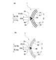
- FIG. 9 (a) and 9 (b) are respectively a side seal portion (seal edge portion) on one side and the vicinity thereof in FIG. 3 in a state where the waist opening of the diaper shown in FIG. 3 is expanded.
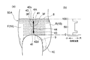
- Fig.10 (a) is a side view of 1st Embodiment (pants-type disposable diaper) of the underpants type wearing article of this invention
- FIG.10 (b) is the seal edge part of the side seal part of 1st Embodiment. It is a graph which shows distribution of the fusion strength of.
- FIG. 11 is a view corresponding to a partially enlarged view of FIG. 6A in the first embodiment of the manufacturing method of the present invention.
- FIG. 12A is a graph showing the relationship between the width of the slit (light passage portion), the fusion strength of the seal edge, and the seal width.
- FIG. 12B is a schematic diagram showing how the pressurization state of the target portion irradiated with laser light changes when the width of the slit (light passage portion) is changed.
- FIG. 12C is an explanatory diagram of the seal width.
- FIG. 13 is a schematic cross-sectional view showing a laser beam passage and its vicinity in the laser-type bonding apparatus used in the second embodiment of the manufacturing method of the present invention.
- FIG. 14 is a view showing a state in which the light passage portion of the laser beam and the vicinity thereof in the laser type bonding apparatus shown in FIG.
- FIG. 13 are viewed from the outer surface side of the cylindrical roll on which the diaper continuous body (band-shaped exterior body) is arranged. is there.
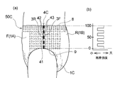
- Fig.15 (a) is a side view of 2nd Embodiment (pants-type disposable diaper) of the underpants type wearing article of this invention
- FIG.15 (b) is the seal edge part of the side seal part of 2nd Embodiment. It is a graph which shows distribution of the fusion strength of.
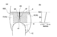
- FIG.16 (a) is a side view of 3rd Embodiment (pants-type disposable diaper) of the underpants type wearing article of this invention
- FIG.16 (b) is the seal edge part of the side seal part of 3rd Embodiment. It is a graph which shows distribution of the fusion strength of.
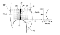
- Fig. 17 (a) is a side view of the fourth embodiment (pants-type disposable diaper) of the pants-type wearing article of the present invention
- Fig. 17 (b) is a seal edge of the side seal portion of the fourth embodiment. It is a graph which shows distribution of the fusion strength of.
- Fig.18 (a) is a side view of 5th Embodiment (pants type disposable diaper) of the underpants type wearing article of this invention
- FIG.18 (b) is a seal edge of the side seal part of 5th Embodiment. It is a graph which shows distribution of the fusion strength of.
- FIG.19 (a) is a side view of 6th Embodiment (pants-type disposable diaper) of the underpants type wearing article of this invention
- FIG.19 (b) is a seal edge of the side seal part of 6th Embodiment. It is a graph which shows distribution of the fusion strength of.
- FIG. 20A is an explanatory diagram of a preferable manufacturing method of the diaper of the fourth embodiment (corresponding to FIG. 11)
- FIG. 20B is an explanatory diagram of a preferable manufacturing method of the diaper of the fifth embodiment ( FIG. 11 is a diagram corresponding to FIG.
- the present invention relates to a pants-type wearing article having a side seal portion excellent in flexibility or touch, and excellent in ease of tearing and feeling of tearing, and a method for manufacturing the same.
- One of the main features of the present invention includes an exterior body that forms an outer surface of a worn article, and a pair of side seals in which both side edges of the exterior body in the front body and both side edges of the exterior body in the back body are joined.
- a pant-type wearing article in which a waist opening and a pair of leg openings are formed, the side seal part is the edge of the exterior body in the front body and the edge of the exterior body in the back body is the side seal
- a device for improving the ease of tearing and the tearing feeling on the seal edge hereinafter improved tearability
- this tearability improving means is, for example, by irradiating a laser beam to a predetermined portion of the belt-shaped exterior body in a state where the front body side and the back body side are overlapped in the manufacturing process of the pants-type wearing article, When the outer body is divided into lengths for individual wearing articles, and at the same time, the cut edges of the laminated outer body produced by the division are fused together to form a pair of side seal parts. It is particularly useful.
- FIG. 1 The outline of the manufacturing method of the underpants type disposable diaper using the laser type
- a diaper 1 that is a manufacturing object of a manufacturing method using this laser type bonding apparatus includes an absorbent main body 2 and an exterior body 3 that forms the outer surface of a wearing article.
- a pants-type disposable diaper in which B1 and B1 are joined to form a pair of side seal portions 4 and 4, a waist opening 8 and a pair of leg openings 9 and 9.
- the exterior body 3 is positioned on the non-skin contact surface side of the absorbent main body 2 and fixes the absorbent main body 2.
- the pair of side seal portions 4, 4 in the diaper 1 extends in the longitudinal direction of the side seal portion 4, with the edge of the exterior body 3 in the front body F and the edge of the exterior body 3 in the back body R, respectively.
- the sealing edge part 41 couple
- the diaper 1 has a longitudinal direction X corresponding to the wearer's front-rear direction and a lateral direction Y orthogonal to the wearer's front-rear direction in a developed and extended plan view as shown in FIG.
- the diaper 1 can be divided into a crotch part 1C arranged at the crotch part at the time of wearing, and an abdominal side part 1A and a back side part 1B located in the longitudinal direction X.
- the exterior body 3 in the crotch part 1 ⁇ / b> C is formed with recesses for forming leg openings 9, 9 at the left and right side edges along the vertical direction X.
- the diaper 1 can be divided into a front body F and a back body R with a virtual center line CL that bisects the diaper 1 in the vertical direction X as a boundary.
- a skin contact surface is a surface directed to a wearer's skin side at the time of wearing in a pants type wearing article or its constituent member (for example, an absorptive main part), and a non-skin contact surface is In the pants-type wearing article or its constituent members, it is a surface directed to the side opposite to the wearer's skin side (clothing side) when worn.
- the vertical direction X corresponds to the direction (longitudinal direction) along the long side of the absorbent main body 2 which is a disposable diaper or its constituent member
- the horizontal direction Y is the absorbent which is a disposable diaper or its constituent member. It coincides with the width direction of the main body 2.
- the absorbent main body 2 has a vertically long shape in one direction (longitudinal direction X), and a surface sheet (not shown) that forms a skin contact surface; A back sheet (not shown) that forms a non-skin contact surface, and a liquid-retaining absorbent (not shown) interposed between the two sheets. And has a long shape in the same direction.
- the absorbent main body 2 is joined to a central portion of the outer package 3 by a known joining means (adhesive or the like) so that the longitudinal direction thereof coincides with the longitudinal direction X of the diaper 1 in the unfolded and extended state.
- the expanded and extended state means that the side seal portion is peeled off, the diaper is set in the expanded state, the elastic member of each part is expanded in the expanded diaper, and the design dimensions (the influence of the elastic member is eliminated at all). In this state, it is expanded until it becomes the same size as when expanded in a flat shape.
- the outer package 3 is arranged on the outer layer sheet 31 that forms the outer surface of the diaper 1 (non-skin contact surface of the outer package 3), and on the inner surface side of the outer layer sheet 31.
- An inner layer sheet 32 that forms the inner surface of 1 (skin contact surface of the exterior body 3), and a plurality of thread-like or belt-like elastic members 5, 6, and 7 fixed between the sheets 31 and 32 with an adhesive. It is configured to include.
- the two sheets 31 and 32 are joined to each other at a predetermined site by an adhesive or heat seal (not shown).
- the exterior body 3 (the outer layer sheet 31 and the inner layer sheet 32) includes a resin material and is formed using the resin material as a main component.
- the resin material includes a heat-sealable synthetic resin such as polyethylene, polyethylene terephthalate, and polypropylene.
- the nonwoven fabric include air-through nonwoven fabric, heat roll nonwoven fabric, spunlace nonwoven fabric, spunbond nonwoven fabric, and melt blown nonwoven fabric.
- the manufacturing method of the diaper 1 exists in the superposition
- polymerization pressurization process which makes the formation planned site
- the belt-shaped outer package 3 (outer layer sheet 31, inner layer sheet 32) is folded in the width direction.
- the front body side and the back body side of the strip-shaped exterior body 3 to which the absorbent main body 2 is fixed are overlapped with each other, whereby “a precursor of a pants-type disposable diaper in which a side seal portion is not formed is unidirectional.
- a continuous diaper 10 is produced.
- sticker part formation process as shown in FIG. 1, the strip
- the pants comprising the exterior body 3 having a pair of side seal portions 4 and 4 by fusing the cut edges of the plurality of exterior bodies 3 (the outer layer sheet 31 and the inner layer sheet 32) in a laminated state generated by The mold disposable diaper 1 is continuously manufactured.
- the waist elastic member 5 forming the waist gather, the waist elastic member 6 forming the waist gather, and the leg elastic member 7 forming the leg gather have a predetermined elongation rate.
- a plurality of each are arranged in the stretched state.
- the leg elastic member 7 is arranged while forming a predetermined leg-circumferential pattern via a known swing guide (not shown) that reciprocates perpendicular to the sheet flow direction.
- an adhesive coating machine (see FIG. (Not shown) to apply hot melt adhesive.
- the elastic members such as the waist elastic member 5 and the waistline elastic member 6 are divided by the laser light irradiation in the sheets 31 and 32 (the site where the side seal portion 4 is to be formed, reference numeral 10C in FIG. 6).
- an adhesive is preferable to apply an adhesive to the adhesive.
- a hot melt adhesive is intermittently applied to the waist elastic member 5 and the waist elastic member 6 by an adhesive application machine (not shown) before being arranged between the sheets 31 and 32. May be.
- a plurality of joint portions for joining the belt-like outer layer sheet 31 and the belt-like inner layer sheet 32 between the two adjacent waistline elastic members 6 and 6, It is also preferable to use a convex roll and a corresponding joining means (not shown) such as an anvil roll.
- the plurality of waistline elastic members 6 and the plurality of leg portions are made by using elastic member precut means (not shown) so as to correspond to positions where the absorbent main body 2 described later is disposed.
- the elastic member 7 is pressed and divided into a plurality of pieces so that the contraction function is not expressed.
- the elastic member precut means include an elastic member dividing portion used in the method for manufacturing a composite elastic member described in JP-A-2002-253605.
- an adhesive such as a hot melt adhesive is applied in advance to the absorbent main body 2 manufactured in a separate process (not shown), and the absorbent main body 2 is rotated by 90 degrees. Then, it is intermittently supplied and fixed on the inner layer sheet 32 constituting the strip-shaped outer package 3.
- the adhesive for fixing the absorbent main body may be preliminarily applied not to the absorbent main body 2 but to the position where the absorbent main body 2 is arranged in the inner layer sheet 32.
- leg hole LO ' is formed inside the annular part enclosed by the leg part elastic member 7 in the strip
- This leg hole forming step can be carried out by using a technique similar to that in a conventional method for manufacturing this type of article, such as a rotary cutter and a laser cutter.
- the leg hole is formed after the absorbent main body 2 is arranged on the belt-shaped outer package 3, but the leg hole may be formed before the absorbent main body 2 is arranged.
- the strip-shaped exterior body 3 is folded in the width direction (a direction perpendicular to the conveying direction of the exterior body 3). More specifically, as shown in FIG. 5, both side portions 3 a, 3 a along the transport direction of the strip-shaped exterior body 3 are folded back so as to cover both ends in the longitudinal direction of the absorbent main body 2. After fixing both ends in the longitudinal direction, the outer package 3 is folded in the width direction together with the absorbent main body 2 (polymerization step in the polymerization pressure step). In this way, the diaper continuous body 10 is obtained.
- the diaper continuous body 10 thus manufactured is irradiated with laser light using a laser bonding apparatus 20 to form a pair of side seal portions 4 and 4 (side seal portion).
- a pants-type disposable diaper 1 having an exterior body 3 having a pair of side seal portions 4 is continuously manufactured.
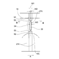
- the laser type bonding apparatus 20 will be described.
- the laser type bonding apparatus 20 is arranged in a hollow cylindrical roll 23 that is rotationally driven in the direction of arrow A and a hollow portion of the cylindrical roll 23 as shown in FIG.
- a belt-type pressure device 26 including an irradiation head 35 that irradiates a laser beam 30 toward a cylindrical (annular) support member 21 that forms a peripheral surface portion 23, and an endless pressure belt 24 (pressing member).
- the laser-type joining device 20 includes a tension adjusting mechanism (not shown) that can adjust the tension of the pressure belt 24 wound around the outer peripheral surface of the annular support member 21 (the peripheral surface portion of the cylindrical roll 23). By adjustment, the pressure applied to the diaper continuous body 10 (sheet laminated body) can be appropriately adjusted by the support member 21 and the pressure belt 24.
- the support member 21 forms a peripheral surface portion (contact portion with the workpiece) of the cylindrical roll 23, and is between a pair of annular frames 22, 22 that form both ends of the cylindrical roll 23 in the rotation axis direction. It is pinched and fixed.
- the support member 21 is made of a metal material such as iron, aluminum, stainless steel, or copper, or a material having heat resistance such as ceramics.
- the support member 21 has a light passage portion 27 through which laser light can pass. As shown in FIG. 1, FIG. 6A and FIG. 6B, the support member 21 has a slit-like opening 27 that penetrates the support member 21 in the thickness direction as a light passage portion. .
- the opening 27 has a rectangular shape in plan view, and the longitudinal direction of the opening 27 intersects with the conveyance direction A of the diaper continuous body 10 (band-shaped exterior body 3).
- a plurality of cylinders are formed at predetermined intervals in the circumferential direction of the cylindrical support member 21 so as to coincide with the direction parallel to the axial length direction of the rotation shaft (the direction indicated by the symbol X in FIG. 6A).
- the support member 21 allows the laser light to pass through the opening 27, but does not allow the laser light to pass (transmit) at portions other than the opening 27.
- a method of forming the opening 27 in the support member 21 1) etching, punching, laser processing, or the like at a predetermined position of the support member 21 made of a single annular member having the same length as the circumferential length of the annular frame 22. 2)
- the support member 21 is replaced with a single annular member, and a plurality of curved rectangular members are used as the support member 21, and the plurality of members are connected between the pair of frames 22, 22.
- a method of arranging the frame body 22 at a predetermined interval in the circumferential direction may be mentioned.
- the interval between two adjacent members forms a slit-shaped opening 27.
- the method 2) is used.
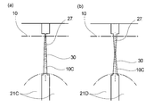
- a support member 21A in which the width of the opening 27A (light passage portion) changes in the longitudinal direction of the opening 27A (light passage portion).
- a projecting portion projecting toward the exterior body 3 is provided in the vicinity of the opening 27 (light passage portion) on the outer surface in contact with the strip-shaped exterior body 3.
- a support member 21 ⁇ / b> B in which the height of the protruding portion changes along the longitudinal direction of the opening (light passage portion).
- each of these members is the cylindrical shape of the cylindrical roll 23. It is rotationally moved in a curved state corresponding to the peripheral surface portion.
- a light passage portion through which laser light can pass is a support member.
- the parting portion 10C that overlaps with the opening 27 itself is not sandwiched between the members 21 and 24, but the vicinity thereof, that is, the portion that overlaps with the vicinity of the opening 27 (opening edge) in the diaper continuous body 10. Is sandwiched between the two members 21 and 24, and therefore does not move before and after the irradiation of the laser beam, and therefore, the cutting edge portion generated by the division of the diaper continuous body 10 by the irradiation of the laser beam does not move. That is, the parting planned portion 10C of the diaper continuous body 10 (portion overlapping the opening 27 in the sheet laminate) is a portion restrained by the pressing force between the members 21 and 24, and the pressing force is practically the same. It is an affected part.
- the support member 21 has a recess 28 on its outer surface (contact surface with the workpiece).
- a plurality of recesses 28 are formed at predetermined intervals in the circumferential direction of the cylindrical support member 21, and a slit-shaped opening 27 is formed in a region (convex part) located between two adjacent recesses 28, 28. Is formed.
- the opening 27 is formed in the center in the circumferential direction of the cylindrical support member 21 in the convex portion.
- the relative thickness of the diaper continuous body 10 is relatively small. It is possible to introduce the diaper continuous body 10 onto the outer surface of the support member 21 so that a large portion (for example, an arrangement region of the absorbent main body 2) is accommodated in the recess 28. Then, when the diaper continuous body 10 is introduced onto the support member 21 in such a manner, as shown in FIG. 6B, the contact surface (the other surface) of the diaper continuous body 10 with the pressure belt 24 (pressing member).
- the belt-type pressure device 26 includes an endless pressure belt 24 (pressing member) and three rolls 25a, 25b, and 25c that rotate while the pressure belt 24 is stretched.
- the rolls 25a, 25b, and 25c may be drive rolls or driven rolls that rotate with the pressure belt 24.
- the pressure belt 24 moves at the same speed as the cylindrical roll 23 (supporting member 21) by using any one or more of the rolls 25a, 25b, and 25c as a driving roll or rotating with the cylindrical roll 23.
- the support member 21 and the pressure belt 24 are preferably maintained in a predetermined temperature range by air cooling, water cooling, or the like.
- a metal or resin belt having heat resistance capable of withstanding the heat generated during processing can be used, for example, a metal material such as iron, aluminum, stainless steel, or the like. Can be used.
- a belt that does not transmit the laser beam irradiated to the workpiece strip-shaped outer package 3 is usually used. You can also.
- an irradiation head 35 that irradiates a laser beam 30 toward a support member 21 that forms a peripheral surface portion of the cylindrical roll 23 is provided in the hollow portion of the hollow cylindrical roll 23.
- the irradiation head 35 is a galvano scanner (device having a mirror on the motor shaft) that freely scans the laser light 30, and the laser light 30 is in a direction parallel to the rotation axis of the cylindrical roll 23 (reference numeral in FIG. 6A).
- a mechanism for making the spot diameter of the laser beam 30 constant is provided.
- the laser irradiation mechanism has such a configuration, so that the irradiation point of the laser light 30 is the circumferential direction of the cylindrical roll 23 and a direction orthogonal to the circumferential direction (a direction indicated by a symbol X in FIG. 6A). It can be arbitrarily moved in both directions of a direction parallel to the rotation axis of the roll 23).
- the diaper continuous body 10 includes a support member 21 that forms a peripheral surface portion of a cylindrical roll 23 that is rotationally driven in the direction of arrow A in a state where a predetermined tension is applied by a guide roll (not shown). After being transported by a predetermined distance in the circumferential direction by rotation of the cylindrical roll 23 so as to be wound around the support member 21, it is separated from the support member 21 by an unillustrated lead roll, nip roll or the like. . As described above, the diaper continuous body 10 is wound around the support member 21 forming the peripheral surface portion of the cylindrical roll 23 with a predetermined tension and is conveyed so as to be in pressure contact with the pressure belt 24.
- the portion sandwiched between the support member 21 and the pressure belt 24 and the vicinity thereof are in a state of being pressurized (compressed) in the thickness direction from before being divided by the laser light irradiation.
- the diaper continuous body 10 contains a nonwoven fabric, the diaper continuous body 10 can be more efficiently compressed, and as a result, the diaper continuous body 10 being compressed is irradiated with laser light.
- this it becomes possible to fuse the cut edges of the plurality of sheets (exterior body 3) constituting the divided portion more reliably, and the side seal portion 4 can be fused. The strength is improved.
- the rotation angle of the support member 21 (cylindrical roll 23) from when the diaper continuous body 10 is introduced onto the support member 21 to when the diaper continuous body 10 leaves the diaper continuous body 10 can be, for example, 90 degrees or more and 270 degrees or less. Is 120 degrees or more and 270 degrees or less.
- the range of the angle (pressure contact angle) at which the diaper continuous body 10 is pressed against the support member 21 by the pressure belt 24 (pressing member) is the entire circumference of the cylindrical support member 21 (cylindrical roll 23). When the pressure contact is 360 degrees, it is preferably 90 degrees or more and 270 degrees or less, and more preferably 120 degrees or more and 270 degrees or less.
- one surface 10a forms the peripheral surface portion of the cylindrical roll 23 and laser light.
- a continuous diaper brought into contact with the outer surface of the support member 21 having a slit-like opening 27 (light passage portion) through which 30 can pass and brought into a pressurized state by the support member 21 and the pressure belt 24 (pressing member).
- the body 10 part where the side seal portion 4 is to be formed
- the diaper continuous body 10 is divided at the same time.
- the cut edges of the plurality of sheets (exterior body 3) in the pressurized state are fused together to form the side seal portion 4 (side seal portion forming step).
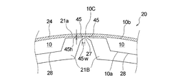
- FIG. 7 is a diagram for explaining how the side seal portion 4 (seal edge) is formed at the same time as the diaper continuous body 10 (band-shaped sheet laminate) is divided using the laser bonding apparatus 20.
- 7 (a) schematically shows a portion 10C (part where the side seal portion 4 is to be formed) scheduled to be divided by the laser beam 30 of the diaper continuous body 10 and its vicinity.
- the diaper continuous part 10C of the diaper continuous body 10 in the illustrated embodiment is the center in the longitudinal direction (conveying direction A) in the region where the absorbent main body 2 of the diaper continuous body 10 is not disposed. It is. 10 C of such parting plan parts are the opening edge part of the waist opening part 8 (refer FIG.
- the 8 layer structure part on which 8 sheets were piled up, and other parts are 4 sheets. It is a four-layer structure part that is superimposed.
- the four-layer structure portion includes two sheets (an outer layer sheet 31 and an inner layer sheet 32) constituting one exterior body 3 in the ventral side part 1A, and a back side part 1B. It consists of the same two sheets 31 and 32 that constitute one exterior body 3, and these four sheets are laminated.
- the eight-layer structure portion is folded so that both side portions 3a and 3a of the strip-shaped outer package 3 cover both longitudinal ends of the absorbent main body 2 when the diaper continuous body 10 is manufactured ( (See FIGS.
- the sheets (inner layer sheet 32) absorb the laser beam 30 and generate heat.
- all of the four sheets 31 and 32 constituting the parting planned portion 10 ⁇ / b> C are sheets (nonwoven fabrics) that absorb the laser beam 30 and generate heat.
- the two sheets of the outer layer sheet 31 and the inner layer sheet 32 that overlap each other in the vicinity of the portion 10C to be divided may be joined by an adhesive or the like before the irradiation with the laser beam 30, or may be joined at all. It is not necessary.
- the diaper continuous body 10 has one surface 10 a abutting against the support member 21, and a parting planned portion 10 ⁇ / b> C (part where the side seal portion 4 is to be formed) is on the slit-shaped opening 27.
- the pressure belt 24 pressing member
- the pressure belt 24 is pressed against the other surface 10b so that it is conveyed in the direction of the arrow A while being introduced onto the support member 21 that rotates in the direction of the arrow A so as to be positioned in the direction of the thickness A.
- Pressure compression
- the laser beam 30 is irradiated through the opening part 27 from the supporting member 21 side with respect to the parting part 10C to be divided in such a conveyance and pressurization state.
- the irradiation point of the laser beam 30 is configured to be arbitrarily movable in the circumferential direction of the cylindrical roll 23, and is set to scan following the movement of the opening 27 along the circumferential direction. Therefore, the laser beam 30 is continuously irradiated for a certain period of time to the parting planned portion 10C located on the opening 27 during the conveyance.
- the forming materials (fibers, etc.) of the sheets 31 and 32 existing in the parting portion 10C are vaporized by the heat generated by the direct irradiation of the laser light 30 and disappear.
- the forming material existing in the vicinity of the parting portion 10 ⁇ / b> C is indirectly heated by the laser beam 30 and melted.
- the parting plan part 10C of a four-layer structure is melted, and in a form in which a single sheet sheet laminate (diaper precursor) is cut from the diaper continuous body 10,
- the cut edges of the four sheets 31 and 32 in the sheet laminate of the single sheets produced by the division, and the diaper continuous 10 are fused together.
- Each of these cut edges is pressed (compressed) by being sandwiched between the support member 21 and the pressure belt 24 from before the formation (before the diaper continuous body 10 is divided by irradiation with the laser beam 30). ).
- the strip-shaped exterior body 3 is divided by the single laser light irradiation, and the exterior body 3 in the two pressurized states generated by the division is thus obtained.
- the fusion and separation are the same with approximately half the laser output compared to the method of fusing the two fusion places with two laser irradiations. It can be carried out in a process, and the diaper 1 can be manufactured efficiently.
- the cut edges of the sheets 31 and 32 are heated and melted during the irradiation of the laser beam 30 and immediately after the end of the irradiation, but are separated from the diaper continuous body 10 by the irradiation of the laser beam 30.
- Each of the leaf diaper precursor and the diaper continuum 10 is maintained in the pressurized state by the support member 21 and the pressure belt 24, and after the irradiation is completed, the air is applied to the outside air, the support member 21 and the pressure belt 24.
- the material is quickly cooled and solidified by heat transfer to form the fused portion 40 in which the forming material (fibers, etc.) of the cut edge is fused and integrated.
- the fused part 40 one of the pair of side seal parts 4, 4 in one diaper 1 is formed.
- the cutting edge portions of the sheets 31 and 32 may be forcibly cooled by using known cooling means such as a suction device and an exhaust device to promote the formation of the fused portion 40.
- the laser beam 30 seems to hit another opening 27 adjacent to the irradiation direction in the direction opposite to the conveyance direction A. And is irradiated to another parting planned portion 10C located thereabove through the other opening 27.
- another part 10C to be divided is divided and fused in the same manner as described above, and the other side seal part 4 (fused part 40) that forms a pair with the previously formed side seal part 4 is formed.
- the pants-type disposable diaper 1 including the exterior body 3 having the pair of side seal portions 4 and 4 is continuously manufactured.
- the diaper is larger than the width W of the slit-shaped opening 27 irradiated with the laser beam 30 (see FIG. 7B.
- the portion 27 may be located at a portion sandwiched between a pair of opening edges along a direction orthogonal to the conveyance direction A. That is, in the diaper continuous body 10, even in a portion that is not sandwiched between the support member 21 and the pressure belt 24 (pressing member), in the vicinity of the opening 27 (opening edge), that is, as described above, The fused part 40 can be formed if the pressure applied by the clamping between the members 21 and 24 is practically affected.
- the side seal portion 4 includes an edge portion 3F of the outer body 3 in the front body F and an edge portion 3R of the outer body 3 in the rear body R.
- the sealing edge part 41 couple
- the seal edge 41 has an outer edge 4a composed of the fused portion 40 in the cross section orthogonal to the direction in which the side seal portion 4 extends when worn. It has a shape recessed toward the inside.
- the fused portion 40 in the seal edge portion 41 has a narrow width W4 that appears on the outer surface of the diaper in the same cross section, and the width W4 is preferably 5 mm or less, more preferably 3 mm or less, and even more preferably 2 mm or less. It is.
- bond part 40 of the seal edge part 41 in this invention has the constant width W4 which appears on the outer surface of a pants
- the width W4 appearing on the outer surface of the pants-type wearing article is constant over the entire length in the longitudinal direction of the side seal part 4 and the maximum value of the width W4 in the entire range in the longitudinal direction of the side seal part 4 It means that the difference from the minimum value of the width W4 is less than 50% of the maximum value.
- the production method of the present invention there is an advantage that the fusion strength can be increased or decreased while maintaining the width W4 substantially constant and maintaining good flexibility and touch.
- the width W4 is narrow as described above. Considering the size of the entire product, even if the width W4 of the side seal portion 4 is swung by 50%, the width W4 is substantially narrow and has the above-described fusion strength and appearance. .
- the direction where the side seal part 4 is extended is extended.
- the side seal part 4 (seal edge part 41) generated by the above-mentioned division in the cross section in the direction perpendicular to the horizontal direction (the same direction as the lateral direction Y of the diaper 1) is the outer edge 4a formed by the outer edge of the fused part 40.
- a fusion arcuate portion 40 of the four sheets 31 and 32 constituting the outer package 3 is formed on the inner side of the diaper 1 including the outer edge 4a and more on the inner side of the diaper 1 than the outer arc 4a.
- the fusion part 40 is formed, and the center part in the thickness direction of the exterior body 3 (the vertical direction in FIG. 7C or FIG. 8) is wider than the both end parts (upper end part and lower end part). . More specifically, the fusion part 40 has a width of the fusion part 40 toward the center part in the thickness direction in a cross-sectional view along the lateral direction Y of the diaper 1 (direction orthogonal to the dividing direction by the laser beam). It gradually becomes wider and is formed in a so-called crescent or half-moon shape (the fused portion 40 shown in FIG. 7 (c) has a crescent shape). It is preferable that the seal edge part 41 has such a shape even in a worn state.
- the side seal portion 4 is harder and softer than other parts of the diaper 1 due to the presence of the fused portion 40 formed by melting and solidifying the sheet forming material, and causes the feeling of wearing the diaper 1 to be reduced.
- the fusion part 40 is formed in a crescent shape or a half moon shape in a cross-sectional view in the width direction of the diaper 1 as described above, the fusion part in the conventional side seal part (for example, in Patent Document 1) Compared to the case where it is formed in a rectangular shape in the same sectional view as shown in FIG. 1 (part indicated by reference numeral 9), the corner 3S of the side edge portion of the exterior body 3 constituting the side seal portion 4 is formed.
- the wearing feeling of the diaper is improved as compared with the conventional product.
- the central portion in the thickness direction of the side edge of the exterior body 3 (the corner 3S on the one surface side of the exterior body 3 and the 3S on the other surface side, which is a part that greatly affects the fusion strength of the side seal portion 4) Since a sufficient amount of the fused portion 40 exists in the center portion between the side portions), the side seal portion 4 has a practically sufficient fusion strength, and the side seal portion 4 is worn while the diaper 1 is worn. Inconveniences such as tearing of the seal 4 hardly occur.
- the side seal part 4 (fusion
- 9A and 9B show the side seal portion 4 (fused portion 40) in a state where the waist opening 8 is expanded when the diaper 1 is worn. In the state where the waist opening 8 is expanded, the side seal portion 4 is normally in a state where the fused portion 40 is exposed as shown in FIG. 9A, but the outer edge 4a of the side seal portion 4 is the exterior. It is difficult to visually recognize from the outside due to the convex arc shape toward the inside of the body 3 and the fact that the fused portion 40 is smaller than the conventional side seal portion (fused portion).
- the outer edge 4a of the side seal portion 4 has a convex arc shape toward the inner side of the exterior body 3, so that depending on the forming material of the sheets 31, 32, as shown in FIG.
- the corner 3S of the side edge of the exterior body 3 on the abdominal side 1A side and the corner of the side edge of the exterior body 3 on the back side 1B side The portion 3S may approach and the separation distance between the corner portions 3S and 3S may be reduced. Therefore, the fusion part 40 located between the two corners 3S and 3S is difficult to touch by the hand and is located on the outer side of the diaper 1 closer to the diaper 1 than the fusion part 40. Therefore, not only the feeling of wearing the diaper 1 but also the appearance is improved.
- the laser beam irradiated to the diaper continuous body 10 is absorbed by the sheets (the outer layer sheet 31 and the inner layer sheet 32) constituting the outer package 3 to generate heat.
- a laser beam having a wavelength is used.
- the “sheet constituting the exterior body” is not limited to the sheet (for example, the outer layer sheet 31 in the above-described embodiment) constituting one surface of the exterior body (the contact surface with the support member 21). Any sheet may be used as long as the sheet is configured. Whether or not the laser light applied to the exterior body has an oscillation wavelength that is absorbed by the sheet and generates heat for the individual sheets constituting the exterior body depends on the material of the sheet and the laser light to be used.
- the laser beam may be CO 2 laser, YAG It is preferable to use a laser, an LD laser (semiconductor laser), a YVO4 laser, a fiber laser, or the like.
- the oscillation wavelength that can be absorbed by the sheet and cause the sheet to generate heat is, for example, 8.0 ⁇ m or more and 15 It is preferable to use 0.0 ⁇ m or less, and it is particularly preferable to use an oscillation wavelength of 9.0 ⁇ m or more and 11.0 ⁇ m or less of a CO 2 laser in which a high-power laser device exists.
- the spot diameter of laser light, laser output, and the like can be appropriately selected in consideration of the material and thickness of the sheet constituting the exterior body.
- [Tearability improvement means] A pair of side seals 4 and 4 obtained through the process in which the diaper 1 which is the manufacturing object of the manufacturing method using the laser type bonding apparatus described above, that is, the division and welding of the outer package 3 are performed simultaneously.
- the diaper 1 which comprises is excellent in the softness
- the fusion strength tends to be uniform in the longitudinal direction of the side seal portion, and the ease of tearing and the feeling of tearing tend to be insufficient.
- the diaper 1 is provided with means for improving tearability for the purpose of enhancing the ease of tearing and the feeling of tearing.
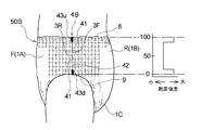
- FIG. 10 shows a first embodiment of the pant-type wearing article of the present invention (pants-type disposable diaper 50A).
- the pair of side seal portions 4A in the diaper 50A of the first embodiment is similar to the pair of side seal portions 4 in the diaper 1 described above, and the outer edge portion 3F of the outer body 3 in the front body F and the outer body 3 in the rear body R.
- the edge portion 3R forms a seal edge portion 41 joined by a continuous linear fusion portion 40 extending in the longitudinal direction of the side seal portion 4A.
- the structure and forming method of the seal edge 41 are the same as the seal edge 41 in the diaper 1 described above.
- the difference between the diaper 50A of the first embodiment and the diaper 1 described above is that, as shown in FIG.
- the seal edge portion 41 constituting the side seal portion 4A has a weakly bonded region 42 having a relatively low fusion strength. And a high bonding region 43 having a relatively high fusion strength. “Relatively low” means “low” compared to the contrasting region, and “relatively high” means “high” compared to the contrasting region.
- the width W4 of the fused portion 40 appearing on the outer surface of the diaper is the same over the entire length in the longitudinal direction of the side seal portion (seal edge portion). However, for convenience of explanation, the width of the side seal portion (seal edge portion) is changed to a width corresponding to the strength of the fusion strength. That is, the lower the fusion strength, the narrower the width, and the thicker the higher the fusion strength.
- the fusion strength is the fusion strength between the outer body 3 on the front body F side and the outer body 3 on the rear body R side in the seal edge 41, and a preferable measurement method is as follows.
- ⁇ Measurement method of fusion strength> From the pants-type wearing article, the side seal part 4 is located in the center in the longitudinal direction, and has a width having a part of the outer body 3 on the front body F side and a part of the outer body 3 on the rear body R side on both sides thereof. A 10 mm strip-shaped test piece is cut out, and the test piece is fixed between chucks of a tensile tester (for example, Tensilon “RTC series” manufactured by A & D).
- a tensile tester for example, Tensilon “RTC series” manufactured by A & D.
- test piece is pulled at an extension speed of the interval between chucks of 300 mm / min until the outer body 3 on the front body F side and the outer body 3 on the rear body R side are completely divided in the longitudinal direction. .
- the maximum value of the tensile stress at that time is defined as the fusion strength.
- the seal edge 41 in the side seal portion 4A of the diaper 50A of the first embodiment has an end weakly bonded region 42u (weakly bonded region) having a relatively low fusion strength at the end on the waist opening 8 side.
- a high joint region 43 having a relatively high fusion strength is provided at a portion adjacent to the end weak joint region 42u.
- the side seal portion 4A is formed by forming the seal edge portion 41 similar to the seal edge portion 41 of the diaper 1, the side seal portion 4A has flexibility and touch. Is excellent. Moreover, since it has the edge part weak junction area
- the diaper 50A of the first embodiment has an intermediate joint region 44 having a fusion strength intermediate between the end weak joint region 42u and the high joint region 43 at the center in the longitudinal direction of the side seal portion 4A. ing.
- FIG. 10B is a graph showing the fusion strength of the seal edge at each position when the lower end position of the side seal portion is 0 and the upper end position is 100.
- an end weakly bonded region 42d (weakly bonded region) having a relatively low fusion strength is also provided at the end of the seal edge 41 on the side of the leg opening 9 in the side seal portion 4A. And also has a high bonding region 43 having a higher fusion strength than that of the end weakly bonded region 42d in the adjacent portion of the end weakly bonded region 42d in the longitudinal direction of the side seal portion 4A. Yes. Therefore, the side seal portion 4A can be easily torn from the leg opening 9 side, and the diaper (wearing article) removing operation can be performed smoothly.
- each region has the following fusion strength measured by the measurement method described above. It is preferable.
- the fusion strength at the end weakly bonded regions 42u and 42d is preferably 18 N / 10 mm or less, more preferably 15 N / 10 mm or less, preferably 1 N / 10 mm or more, more preferably 1.5 N / 10 mm. That's it.
- the fusion strength in the high bonding region 43 is preferably 2 N / 10 mm or more, more preferably 2.5 N / 10 mm or more, preferably 20 N / 10 mm or less, more preferably 18 N / 10 mm or less.
- the fusion strength in the intermediate bonding region 44 is preferably 1.5 N / 10 mm or more, more preferably 2 N / 10 mm or more, and preferably from the viewpoint that a bond that does not come off at the time of wearing and is easy to tear after use is required. It is 18 N / 10 mm or less, more preferably 15 N / 10 mm or less.
- the diaper 50A of the first embodiment is manufactured in the same manner as the manufacturing method described in the basic technique except that the support member 21A is used.
- the diaper continuous body 10 (band-shaped exterior body 3) in a state where the front body side and the back body side are overlapped is introduced into a cylindrical roll 23 having a peripheral surface portion made of a support member 21A.
- the opening 27A is formed with respect to the formation planned portion 10C of the side seal portion of the diaper continuous body 10 (band-shaped outer package 3) while applying pressure between the pressure belt 24 and the support member 21A.
- the laser beam 30 is irradiated. As shown in FIG.
- the opening 27 ⁇ / b> A (light passage portion) in the support member 21 ⁇ / b> A includes a wide portion 52, a narrow portion 53 that is narrower than the wide portion 52, and an intermediate portion between the wide portion 52 and the narrow portion 53.
- An intermediate width portion 54 having a width is provided.
- the “intermediate width” is a width wider than the narrow portion 53 and narrower than the wide portion 52.
- a corresponding cross-sectional view (a cross-sectional view taken along the line III-III in FIG. 11) in a portion irradiated with laser light through the narrow portion 53 appears in the same manner as FIG.
- the portion irradiated with the laser beam through the narrow portion 53 is subjected to the same process as the laser beam irradiation shown in FIG.
- the exterior body 3 is divided, and the cut edges of the laminated exterior body 3 are generated by the division.
- the portion 10C where the side seal portion is to be formed in the portion irradiated with laser light through the intermediate width portion 54 or the wide portion 52, the wider the width, the relatively less the pressure is applied.
- the laser beam 30 is irradiated to the diaper continuous body 10 in a state where the outer package of the sheet is not sufficiently adhered to the narrow portion 53.
- the outer body 3 is divided at the portion irradiated with the laser light through the intermediate width portion 54 or the wide portion 52, the melting of the cut edges of the laminated outer body 3 caused by the division occurs.
- the fusion strength by the fusion part 40 generated by the adhesion is weaker than that of the part irradiated with the laser light through the narrow part 53.
- FIG. 12A shows the following conditions while pressing with a laser-type bonding apparatus shown in FIG.
- FIG. 12B is a schematic diagram showing how the pressurization state of the target portion irradiated with laser light changes when the width of the slit (light passage portion) is changed.
- Laser light irradiation conditions Spot diameter: 0.3 mm Pressure: 0.4 MPa
- the width of the light passage part is excessively increased with respect to the spot diameter, the fusion strength becomes zero, and the edge of the exterior body in the front body before fusion and the edge of the exterior body in the back body are not joined. Part is generated. Accordingly, a support member in which such a relationship is obtained in advance for each laminated structure of the exterior body to be irradiated with laser light, and the width of the light passage portion is appropriately controlled according to the fusion strength to be applied to the seal edge portion. 11, for example, as shown in FIG. 11, the laser beam is emitted from the central portion of the slit-shaped opening 27 ⁇ / b> A from the one end side to the other end side in the axial length direction of the cylindrical roll.
- the diaper 50A can be manufactured only by scanning linearly at a constant speed without changing the output.
- the support member whose width of the light passage portion changes in the longitudinal direction of the light passage portion is used, and the laser beam is irradiated through the light passage portion, thereby providing flexibility and touch.
- the ratio (W2 / W1) of the width W2 of the narrow portion 53 to the width W1 of the wide portion 52 is, for example, preferably 0.025 or more, more preferably 0.05 or more, and preferably 0.9. Or less, more preferably 0.85 or less, and preferably 0.025 to 0.9, more preferably 0.05 to 0.85.
- the ratio (W3 / W1) of the width W3 of the intermediate width portion 54 to the width W1 of the wide portion 52 is, for example, preferably 0.05 or more, more preferably 0.075 or more, and preferably 0.95. Or less, more preferably 0.9 or less, and preferably 0.05 to 0.95, more preferably 0.075 to 0.9.
- FIG. 13 is an explanatory diagram of a second embodiment of the manufacturing method of the present invention for manufacturing the diaper 50A of the first embodiment.
- the exterior body 3 side is located in the vicinity of the opening 27 (light passage portion) in the outer surface 21a with which the strip-shaped exterior body 3 contacts.
- the support member 21 ⁇ / b> B has a protrusion 45 that protrudes in the height direction, and the height 45 h of the protrusion 45 changes discontinuously along the longitudinal direction of the opening 27 (light passage portion).
- the light passing portion through which the laser light can pass is composed of a slit-shaped opening 27 that penetrates the support member 21 in the thickness direction.
- the portion of the exterior body 3) that overlaps with the opening 27 does not generate pressure applied by being sandwiched between the support member 21 and the pressure belt 24 (pressing member). Since the portion 10 ⁇ / b> C is a portion in which the applied pressure is substantially affected, the fused portion 40 is formed. In order to form the fused portion 40 more stably, it is effective to further increase the pressure applied by the clamping between the members 21 and 24.
- a protruding portion 45 is formed on the outer surface 21a on the outer diaper continuous body 10 side (on the belt-shaped outer package 3 side and the pressure belt 24 side) with respect to the outer surface 21a. More specifically, the protrusion 45 is formed along each of a pair of opening edges extending in the longitudinal direction of each of the plurality of openings 27 (the width direction of the support member 21) on the outer surface 21 a of the support member 21. Each protrusion 45 is formed to extend in the longitudinal direction along the opening 27.
- Each protrusion 45 has a high-order part 45a, a low-order part 45b, and a middle-order part 45c having different protrusion heights 45h (projection heights from the peripheral part) in the longitudinal direction.
- the lower part 45b has a lower protrusion height 45h than the higher part 45a
- the middle part 45c has a protrusion height 45h higher than the lower part 45b and lower than the higher part 45a.
- the top of the protrusion 45 may be flat or a curved surface having a predetermined curvature, and the curved surface may be parallel to the outer surface 21 a of the cylindrical support member 21.
- a protruding part 45 having a high-order part 45a is formed, so that the diaper continuous body 10 (strip-shaped exterior body) is provided in the vicinity of the high-order part 45a. ) Can be effectively increased in the vicinity of the portion scheduled to be divided, thereby ensuring the division of the diaper continuous body 10 and the fusion of the cut end, and the above-described high bonding region in the seal edge portion 41. 43 can be formed reliably.
- the applied pressure in the vicinity of the part to be divided in the diaper continuous body 10 can be reduced as compared with the vicinity of the higher portion 45a.
- region 43 in the seal edge part 41 mentioned above can be formed efficiently.
- the support member 21B in which the protrusion height of the protrusion 45 changes along the longitudinal direction of the light passage portion 27 is pressed by the support member 21B.
- the protrusion height 45h (see FIG. 13) of the protrusion 45 is preferably 0. 0.1 mm or more, more preferably 1 mm or more, preferably 10 mm or less, more preferably 8 mm or less, preferably 0.1 mm or more and 10 mm or less, more preferably 1 mm or more and 8 mm or less.
- the width 45w of the protrusion 45 is preferably 1 mm or more, more preferably 2 mm or more, and preferably 20 mm or less, more preferably.
- the lower portion 45b has a height difference from the higher portion 45a of preferably 0.1 mm or more, more preferably 0.2 mm or more, and preferably 5 mm or less, more preferably 4 mm or less, more specifically preferably It is 0.1 mm or more and 5 mm or less, More preferably, it is 0.2 mm or more and 4 mm or less.
- the middle portion 45c has a height difference from the high portion 45a of preferably 0.05 mm or more, more preferably 0.1 mm or more, and preferably 4.5 mm or less, more preferably 3.5 mm or less.
- the lower portion 45b may be a portion that does not protrude from the outer surface 21a of the support member 21 at all, instead of the one that protrudes from the outer surface 21a of the support member 21.
- FIG. 15 is a figure which shows the underpants type disposable diaper as 2nd Embodiment of the underpants type wearing article of this invention.
- the seal edge portion 41 in the side seal portion 4B of the diaper 50B of the second embodiment has an end high joint region 43u (high joint region) having relatively high fusion strength at the end on the waist opening 8 side.
- a weakly bonded region 42 having a relatively low fusion strength is provided at a portion adjacent to the end highly bonded region 43u.
- “Weak bonding area” is synonymous with “low bonding area”.
- the side seal portion 4B is formed by forming the seal edge portion 41 similar to the seal edge portion 41 of the diaper 1, the side seal portion 4B is flexible and soft. Is excellent. Moreover, since it has the edge part high joining area
- the end high joint region 43d (high joint region) having a relatively high fusion strength is also provided at the end of the seal edge 41 on the side of the leg opening 9 in the side seal portion 4B.
- a weakly bonded region 42 having a relatively low fusion strength is provided adjacent to the end highly bonded region 43d. Therefore, it is possible to prevent unintended peeling of the side seal part from the end part on the leg opening 9 side during wearing of the side seal part 4A.
- the diaper (wearing article) removal operation can be performed smoothly.
- the strength preferably has a fusion strength equivalent to that of the intermediate joint region 44 in the diaper 50A, and the weak joint region 42 preferably has a fusion strength equivalent to that of the weak joint region 42 in the diaper 50A.
- the diaper 50B of the second embodiment corresponds to the light passing portion 27A corresponding to the end portion on the waist opening portion 8 side and the end portion on the leg opening portion 9 side in the manufacturing method of the first embodiment of the present invention described above. It is manufactured in the same manner as in the method of the first embodiment except that it is replaced with one having a relatively narrow narrow portion at a position where it has a relatively wide wide portion between the narrow portions. be able to.
- the diaper 50B of 2nd Embodiment is the manufacturing method of the 2nd embodiment of this invention mentioned above, the support member 21B, the edge part by the side of the waist opening part 8 in the vicinity of the light passage part 27, and leg opening It can be manufactured in the same manner as in the method of the second embodiment except that a high-order part 45a is provided at a position corresponding to the end part on the part 9 side and a low-order part 45b is provided between the high-order parts 45a. .
- FIG. 16 is a figure which shows the underpants type disposable diaper as 3rd Embodiment of the underpants type wearing article of this invention.
- a weak joint region 42 and a high joint region 43 having different fusion strengths are formed on the seal edge 41 constituting the side seal portion 4C.
- the portions 4C are alternately formed in the longitudinal direction, and a plurality of portions are formed.
- the seal edge portion 41 constituting the side seal portion 4C and the weakly bonded regions 42 and the high bonded regions 43 having different fusion strengths are alternately formed.
- they are alternately peeled off, and vibrations and the like are transmitted to the hand, so infant guardians, elderly people, caregivers, etc. fully realize that the side seal 4C has been torn. It is capable of tearing and is excellent in tearing.
- the light passing portion 27A is formed by alternately forming the narrow portions 53 and the wide portions 52 in the longitudinal direction. It can be manufactured in the same manner as the method of the first embodiment except that it is replaced. Further, in the diaper 50C of the third embodiment, in the manufacturing method of the second embodiment of the present invention described above, the support member 21B is light-transmitted between the high-order part 45a and the low-order part 45b in the vicinity of the light passage part 27. It can be manufactured in the same manner as in the method of the second embodiment except that one formed alternately along the longitudinal direction of the portion 27 is used.
- FIGS. 17 to 19 are views showing pants-type disposable diapers as fourth to sixth embodiments of the pants-type wearing article of the present invention.
- the diaper 50D of the fourth embodiment, the diaper 50E of the fifth embodiment, and the diaper 50F of the sixth embodiment have continuous fusion strength at the seal edge portions 41 constituting the side seal portions 4D, 4E, 4F, respectively.
- the seal edge portion 41 constituting the side seal portion 4D is the other end on the leg opening 9 side from the one end portion on the waist opening 8 side of the side seal portion 4D.
- the sealing edge portion 41 constituting the side seal portion 4E is located on the side of the waist opening 8 of the side seal portion 4E.
- the sealing edge portion 41 constituting the side seal portion 4F is after the fusion strength gradually decreases from one end portion on the side of the waist opening 8 of the side seal portion 4F toward the center portion.
- the fusion strength gradually increases from the central portion toward the other end on the leg opening 9 side.
- the width of the opening 27 is used instead of the support member 21 used in the manufacturing method of the basic technology described above.
- 20A shows a support member 21C that can be preferably used for manufacturing the diaper 50D of the fourth embodiment
- FIG. 20B shows a support member that can be preferably used for manufacture of the diaper 50E of the fifth embodiment. 21D was shown.
- a diaper (wearing article) is provided at the end of the side seal portion 41D on the leg opening 9 side of the seal edge portion 41D because the seal edge portion 41 has a weak fusion strength.
- the side seal portion 4D can be easily torn from the leg opening 9 side, and the diaper (wearing article) removal operation can be performed smoothly.
- the fusion strength is increased from the leg opening 9 side toward the waist opening 8 side, unintentional peeling of the seal edge extends over a wide range of the side seal part 4D during wearing, It is possible to prevent the diaper (wearing article) from slipping off or coming off.
- a region where the sealing strength of the seal edge 41 is weak is formed on the end of the seal opening 41 on the side of the waist opening 8 and the end of the leg opening 9 on the side seal 4E. Therefore, when removing the diaper (wearing article), the side seal portion 4E can be easily torn from the waist opening 8 side or the leg opening 9 side, and the diaper (wearing article) removal operation can be performed smoothly. Can do. Further, since the fusion strength at the longitudinal center portion of the side seal portion 4E is high, unintentional peeling of the seal edge extends over a wide range of the side seal portion 4E during wearing, and the diaper (wearing article) ) Can be prevented from falling off or coming off.
- the diaper 50F of the sixth embodiment can prevent unintended peeling of the side seal portion from the end on the waist opening 8 side or the end on the leg opening 9 side during wearing.
- the diaper (wearing article) removal operation can be performed smoothly.
- the side seal part 4 (fusion part 40) becomes difficult to visually recognize from the outside in the wearing state or the natural state (contracted state) of the diaper 1, for example, after the use of the diaper 1, the protection from the infant who is the wearer When a person (for example, a mother) removes the diaper, it is difficult to find the side seal portion 4, and there is a possibility that it takes time to remove the diaper 1.
- the color of the constituent member of the diaper 1 that traverses the side seal portion 4 is changed to the side seal portion as a means for solving such inconvenience due to the decrease in visibility of the side seal portion 4.
- the method of making it differ on the ventral side (front side) and back side (rear side) rather than 4 is mentioned.
- the waist part elastic member 5 or the sheet constituting the exterior body 3 is composed of the abdominal side part 1 ⁇ / b> A (front view) and the back side part 1 ⁇ / b> B (back view) of the diaper 1.
- a method of changing the color of the sheet 32 or the like is employed, the side seal portion 4 is positioned at the color switching portion, so that the visibility of the side seal portion 4 is further enhanced, and the occurrence of the inconvenience is further effectively prevented.
- the melting of the outer package using the heat source is not limited to the laser beam irradiation to the outer package, and as a non-contact heat source, infrared or halogen light may be used. It can also be carried out by thermocompression bonding of the exterior body using a known heat roll device or the like, or applying ultrasonic vibration to the exterior body using a known ultrasonic vibration device or the like.
- segmentation of an exterior body and formation of a junction part in the said side seal part formation process may be simultaneous, and may be divided after formation of a junction part.
- the pant-type wearing article of the present invention is scanned with laser light when irradiating laser light linearly along the longitudinal direction of the slit-shaped opening (light passage part) in the manufacturing method of the basic technology.
- it can be manufactured by appropriately changing the output of the irradiated laser beam or the scanning speed. For example, it is possible to form a seal edge in which a region irradiated with an increased output is a high joint region and a region irradiated with a weak output is a weakly bonded region.
- the seal edge where the scanning speed is slowed down and the part that gives a relatively large amount of energy is a high joint area, and the part that fastens the scanning speed and the part that gives a relatively small amount of energy becomes a weak joint area. It can also be formed.
- laser light is added to the part where the fusion strength is to be increased.
- Other parts of the seal edge may be irradiated in advance by irradiating the laser beam only on the part where the fusion strength is to be increased before the laser beam is irradiated or the laser beam is irradiated. It is possible to form a high bonding region having a higher fusion strength than the portion.
- the protrusion height of the protrusion is discontinuously along the longitudinal direction of the light passage in the vicinity of the light passage on the outer surface in contact with the exterior body.
- the portion where the laser beam is irradiated to the portion that is relatively strongly pressed by the narrow portion is formed as a portion where the fusion strength is relatively high, and the portion where the fusion strength is relatively high and the portion where the width is wide.
- the portion where the fusion-bonded portion is formed by irradiating the weakly pressurized portion with the laser beam is a region having a relatively low fusion strength.
- the strip-shaped outer package (sheet laminate) is a stack of four sheets as shown in FIG. 7A, or two, three, or five or more sheets. May be.
- the laser-type bonding apparatus 20 is provided with a mechanism for controlling the tension of the diaper continuous body 10. Also good.
- the exterior body 3 in the embodiment (mode) is not divided into the abdominal part 1A and the dorsal part 1B, but the abdominal part 1A, the crotch part 1C, and the dorsal part 1B.
- the exterior body in the present invention is not limited to such a continuous shape, and is, for example, the stomach side disposed on the wearer's stomach side (front side). It is divided
- seat member distribute
- the polymerization pressurizing step includes a front body side (a belt-like stomach side sheet member) of the belt-like exterior body to which the absorbent main body is fixed.
- a site where the side seal portion is to be formed in the belt-shaped exterior body having a configuration in which the back body side (band-shaped backside sheet member) is superimposed is brought into a pressurized state.
- Pants-type wearing articles such as pants-type disposable diapers with a split-type exterior body can also be divided into a crotch part and an abdominal side part and a back side part extending in front and rear thereof, and the abdominal sheet member is worn when worn It arrange
- seat member is distribute
- seat member are mutually joined in the right-and-left both sides of a pants type wearing article, and a pair of side seal part is formed.
- both side parts along the conveyance direction of each inner layer sheet 32 were folded back so as to cover both ends in the longitudinal direction of the absorbent main body 2, the width direction (longitudinal direction) of the band-shaped outer layer sheet 31 was more than the band-shaped inner layer sheet 32. Absorbs only the extension part of the outer layer sheet 31 that extends outward from the side edge of the inner layer sheet 32 when the sheets 31 and 32 are overlapped.
- the body 2 may be folded back so as to cover both ends in the longitudinal direction.
- the parting plan part 10C of the diaper continuous body 10 is a six-layer structure part in which the opening end part of the waist opening part 8 and its vicinity are overlapped with six sheets, and the other part is four sheets. Becomes a four-layer structure part.
- seat 32 do not need to be folded.
- the end portion on the waist opening 8 side and the end portion weakly bonded regions 42u and 42d on the end portion on the leg opening 9 side are provided, and a high bonding region is provided in the adjacent portion.
- end high joint regions are provided at both the end on the waist opening 8 side and the end on the leg opening 9 side, and the side seal portion is provided in the center in the longitudinal direction.
- the weak joint region is provided, the end high joint region may be provided only in one of the end portion on the waist opening 8 side and the end portion on the leg opening 9 side.
- the following three methods (1) to (3) are exemplified as a method for producing a pants-type wearing article, the following three methods can be implemented by arbitrarily combining two or more.
- (1) In the side seal portion forming step using a support member in which the width of the light passage portion changes discontinuously or continuously in the longitudinal direction of the light passage portion, the strength of the fusion strength is applied to the seal edge portion. How to form.
- the method (1) and the method (2) are combined to form a region having a relatively high fusion strength at the seal edge with both sides of the narrow portion of the light passage portion as a high-order portion, while passing the light. It is also possible to form a region having a relatively low fusion strength at the seal edge portion by setting both sides of the wide portion of the portion to a lower portion.
- pant-type wearing article in the present invention is not limited to a pant-type disposable diaper, and may be a pant-type sanitary napkin. It may be a diaper cover or the like that does not include
- the description omitted in one embodiment described above and the requirements of only one embodiment can be applied to other embodiments as appropriate, and the requirements in each embodiment can be appropriately changed between the embodiments. Can be substituted.
- An exterior body that forms the outer surface of the wearing article is provided, and a pair of side seal portions, a waist opening portion, and a pair of leg openings are formed by joining both side edges of the exterior body in the front body and both side edges of the exterior body in the back body
- a pants-type wearing article in which a part is formed The side seal portion includes a seal edge portion in which the edge portion of the exterior body in the front body and the edge portion of the exterior body in the back body are joined by a continuous linear fusion portion extending in the longitudinal direction of the side seal portion.
- the pants-type wearing article which is formed and has the sealing edge portion continuous over the entire length of the side seal portion and having a strength of fusion strength in its longitudinal direction.
- the exterior body includes an outer layer sheet that forms an outer surface of a worn article, an inner layer sheet that is disposed on the inner surface side of the outer layer sheet, and a plurality of thread-like or belt-like elastic members that are fixed between the two sheets with an adhesive.
- the underpants-type wearing article according to the above ⁇ 1> comprising: ⁇ 3> Between the outer layer sheet and the inner layer sheet, a waist elastic member that forms a waist gather, a waist elastic member that forms a waist gather, and a leg elastic member that forms a leg gather are stretched to a predetermined elongation rate.
- the underpants-type wearing article according to the above ⁇ 2> wherein a plurality of each are arranged in an extended state.
- the exterior body in the front body and the exterior body in the back body include a waist elastic member forming a waist gather or a waist elastic member forming a waist gather
- ⁇ 6> The pants-type wearing article according to any one of ⁇ 1> to ⁇ 5>, wherein the exterior body includes a nonwoven fabric, a film, or a laminate sheet of the nonwoven fabric and the film.
- a fusion portion between sheets constituting the exterior body is formed on the outer edge of the seal edge portion, and the fusion portion is in the thickness direction of the exterior body.
- the outer edge of the seal edge portion has a convex arc shape toward the inside of the wearing article, and includes the outer edge and is further inward of the wearing article.
- ⁇ 1> to ⁇ 6 wherein a fusion part between sheets constituting the exterior body is formed, and the fusion part is wider at the center in the thickness direction of the exterior body than both ends.
- the seal edge portion has an end weakly bonded region having a relatively low fusion strength at an end on the waist opening side or an end on the leg opening side, and in the longitudinal direction of the side seal portion.
- the pants-type wearing article according to any one of the above items ⁇ 1> to ⁇ 8> which has a high bonding region having a relatively high fusion strength at a site adjacent to the end weak bonding region.
- the seal edge portion in the side seal portion has an end weak joint region having a relatively low fusion strength at the end on the waist opening side, and the end weakness in the longitudinal direction of the side seal portion.
- the end portion of the side seal portion in the longitudinal direction of the side seal portion has a weakly bonded end portion at the end portion on the leg opening portion side of the seal edge portion, and has a relatively low fusion strength.
- the pants-type wearing article according to any one of the above items ⁇ 1> to ⁇ 10>, wherein the article has a high-bonding region at a site adjacent to the weak-bonding region, the fusion strength being higher than that of the end weak-bonding region. .
- the seal edge portion has an end high joint region having relatively high fusion strength at an end portion on the waist opening side or an end portion on the leg opening side, and in the longitudinal direction of the side seal portion.
- the pants-type wearing article according to any one of the above items ⁇ 1> to ⁇ 8>, which has a weakly bonded region having a relatively low fusion strength at the center.
- the seal edge portion in the side seal portion has an end high joint region having a relatively high fusion strength at the end on the waist opening side, and the end height in the longitudinal direction of the side seal portion.
- the pants-type wearing article according to any one of ⁇ 1> to ⁇ 8>, wherein the article has a weakly bonded region having a relatively low fusion strength at a site adjacent to the bonded region.
- the end portion on the leg opening side of the seal edge in the side seal portion also has an end high joint region with relatively high fusion strength, and the end height in the longitudinal direction of the side seal portion.
- ⁇ 16> The pants-type wearing article according to any one of ⁇ 1> to ⁇ 14>, wherein the sealing edge has a continuously changing fusion strength in a longitudinal direction thereof.
- the sealing edge portion constituting the side seal portion has a fusion strength that continuously decreases from one end portion on the waist opening side of the side seal portion toward the other end portion on the leg opening portion side, The pants-type wearing article according to ⁇ 16>.
- the seal edge portion constituting the side seal portion after the fusion strength gradually increases from the one end portion of the side seal portion on the waist opening side toward the center portion, then the other side on the leg opening portion side from the center portion.
- the pants-type wearing article according to ⁇ 16> wherein the fusion strength gradually decreases toward the end.
- the seal edge portion constituting the side seal portion is formed on the other side of the leg opening portion from the center portion after the fusion strength gradually decreases from one end portion of the side seal portion on the waist opening side toward the center portion.
- the pants-type wearing article according to ⁇ 16> wherein the fusion strength gradually increases toward the end.
- ⁇ 20> The pant mold according to any one of ⁇ 1> to ⁇ 15>, wherein the fusion part has a constant width that appears on the outer surface of the pant-type wearing article over the entire length of the side seal part in the longitudinal direction. Wearing articles.
- the fusion strength at the end weakly bonded region is preferably 18 N / 10 mm or less, more preferably 15 N / 10 mm or less, preferably 1 N / 10 mm or more, more preferably 1.5 N / 10 mm or more.
- the fusion strength in the high bonding region is preferably 2 N / 10 mm or more, more preferably 2.5 N / 10 mm or more, preferably 20 N / 10 mm or less, more preferably 18 N / 10 mm or less.
- the fusion strength in the intermediate joining region is preferably 1.5 N / 10 mm or more, more preferably 2 N / 10 mm or more, preferably 18 N / 10 mm or less, more preferably 15 N / 10 mm or less.
- the pant-type wearing article according to any one of the above items ⁇ 1> to ⁇ 24>, wherein the color of the constituent member of the pant-type wearing article is different between the ventral side and the back side than the side seal portion.
- the pants-type wearing article has a crotch portion arranged in the crotch portion when worn, and a ventral side portion and a back side portion located in the longitudinal direction of the crotch portion,
- the pants-type wearing article can be divided into a crotch part arranged in the crotch part at the time of wearing, and a ventral part and a back part located in the longitudinal direction of the crotch part,
- the pants-type wearing article according to any one of ⁇ 1> to ⁇ 26>, wherein the exterior body has an hourglass-like continuous shape extending from the abdominal side, the crotch part, and the back side.
- the pants-type wearing article can be divided into a crotch part arranged in the crotch part at the time of wearing, and a ventral part and a back part located in the longitudinal direction of the crotch part,
- the exterior body is divided into an abdominal sheet member disposed on the abdominal side part and a back sheet member disposed on the back side part, and the absorbent main body is bridged and fixed to both the sheet members.
- the pants-type wearing article according to any one of ⁇ 1> to ⁇ 27>.
- the width of the light passage portion is changed in the longitudinal direction of the light passage portion by using a support member that changes discontinuously or continuously, and the fusion strength strength of the seal edge portion is increased or decreased.
- the manufacturing method of the underpants type wearing article which forms.
- the light passage part is a method for producing a pants-type wearing article according to the above ⁇ 29>, wherein a narrow part and a wide part narrower than the wide part are alternately formed in the longitudinal direction.
- the light passage part in the support member has a wide part, a narrow part narrower than the wide part, and an intermediate width part having an intermediate width between the wide part and the narrow part.
- the seal edge generated by the laser beam can be obtained by scanning the laser beam having the same spot diameter and the same laser output at a constant speed along the longitudinal direction of the light passing portion and changing the width of the light passing portion.
- the ratio (W2 / W1) of the width W2 of the narrow portion to the width W1 of the wide portion is preferably 0.025 or more, more preferably 0.05 or more, and preferably 0.9 or less.
- the ratio (W3 / W1) of the width W3 of the intermediate width portion to the width W1 of the wide portion is preferably 0.05 or more, more preferably 0.075 or more, and preferably 0.95 or less. More preferably, it is 0.9 or less, preferably 0.05 to 0.95, more preferably 0.075 to 0.9, any one of the above ⁇ 29> to ⁇ 33> Manufacturing method of pants-type wearing articles.
- the side seal portion forming step there is a projecting portion projecting toward the exterior body side in the vicinity of the light passage portion on the outer surface in contact with the exterior body, and the projecting height or width of the projecting portion is that of the light passage portion.
- a method for manufacturing a pants-type wearing article wherein a strength of fusion strength is formed on the seal edge using a support member that changes discontinuously or continuously along a longitudinal direction.
- the protrusion is formed along each of a pair of opening edge portions extending in the longitudinal direction of the light passage portion, and is formed to extend in the longitudinal direction along the light passage portion. In the direction, the projecting height from the peripheral part has a high part, a low part and a middle part that are different from each other,
- the pants according to ⁇ 35> wherein the lower portion has a protruding height lower than that of the higher portion, and the middle portion has a protruding height higher than the lower portion and lower than the higher portion.
- the protrusion height of the protrusion is preferably 0.1 mm or more, more preferably 1 mm or more, preferably 10 mm or less, more preferably 8 mm or less, and preferably 0.1 mm or more and 10 mm or less, More preferably, it is 1 mm or more and 8 mm or less,
- the height difference between the low-order part and the high-order part is preferably 0.1 mm or more, more preferably 0.2 mm or more, and preferably 5 mm or less, more preferably 4 mm or less, more specifically preferably
- the height difference between the middle portion and the high portion is preferably 0.05 mm or more, more preferably 0.1 mm or more, and preferably 4.5 mm or less, more preferably 3.5 mm or less.
- the pant-type wearing article according to any one of the above ⁇ 35> to ⁇ 38>, which is preferably 0.05 mm to 4.5 mm, more preferably 0.1 mm to 3.5 mm.
- Production method. ⁇ 40> Using the support member in which the width of the protruding portion formed in the vicinity of the light passage portion changes discontinuously along the longitudinal direction of the light passage portion, the strength of the fusion strength is formed on the seal edge portion.
- the part where the laser beam is irradiated to the part that is relatively strongly pressed by the narrow part, and the part where the fused part is formed is relatively weak by the part where the fusion strength is relatively high and the part where the width is wide.
- the width 45w of the protrusion is preferably 1 mm or more, more preferably 2 mm or more, and preferably 20 mm or less, more preferably 10 mm or less, more specifically, preferably 1 mm or more and 20 mm or less, more preferably 2 mm or more.
- ⁇ 42> The method for producing a pants-type wearing article according to any one of the above ⁇ 1> to ⁇ 28>, A polymerization pressurizing step for pressing the formation planned site of the side seal part in the belt-shaped exterior body in a state where the front body side and the back body side are overlapped; and While cutting the exterior body by irradiating a laser beam through a light passage portion extending in a direction intersecting the transport direction of the exterior body to the formation planned site of the side seal portion in a pressurized state A side seal part forming step of forming the side seal part by fusing the cut edges of the laminated outer package produced by the division, In the said side seal part formation process, the manufacturing method of the underpants type wearing article which forms the strength of fusion strength in the said seal edge part by changing the output or scanning speed of the laser beam to irradiate.
- a waist gather is formed between the belt-like outer layer sheet constituting the outer package continuously supplied from the raw fabric roll and the belt-shaped inner layer sheet constituting the outer package continuously supplied from the raw roll.
- the manufacturing method of the underpants type wearing article of any one of 45>. ⁇ 47> By feeding and pressing a belt-like outer layer sheet and a belt-like inner layer sheet sandwiching a waist elastic member, a waistline elastic member, and a leg elastic member in a stretched state between a pair of nip rolls, a plurality of pieces are provided between the belt-like sheets.
- the belt-like outer layer sheet and the belt-like inner layer sheet constituting the exterior body are hot-melted with an adhesive coating machine on a predetermined portion of one or both of the opposite surfaces of the two sheets before being overlapped.
- the elastic member such as the waist elastic member, the waist elastic member, and the like in the band-shaped outer layer sheet constituting the outer package and the portion to be divided by the laser beam irradiation in the band-shaped inner layer sheet constituting the outer package
- the stretched state is arranged so as to straddle, the pants-type wearing article according to any one of the above items ⁇ 29> to ⁇ 48>, wherein an adhesive is applied to the portion to be divided and the vicinity thereof Method.
- the waist part elastic member and the waistline part elastic member are hot melt type by an adhesive coating machine before being arranged between the belt-like outer layer sheet constituting the exterior body and the belt-like inner layer sheet constituting the body.
- ⁇ 51> Between the two sheets of the outer layer sheet constituting the outer package and the inner layer sheet constituting the outer package, which overlap each other in the vicinity of the part to be divided by the laser beam irradiation, before the laser beam irradiation, The method for producing a pants-type wearing article according to any one of the above items ⁇ 29> to ⁇ 50>, which is not joined.
- the pants-type wearing article according to any one of ⁇ 29> to ⁇ 52>, wherein the side seal portion forming step forms a pair of side seal portions by irradiating a laser beam using a laser type bonding apparatus.
- the laser-type bonding apparatus is configured to rotate a hollow cylindrical roll and a laser beam toward a cylindrical (annular) support member disposed in a hollow portion of the cylindrical roll and forming a peripheral surface portion of the cylindrical roll.
- a belt-type pressure device including an irradiation head for irradiation, an endless pressure belt (pressing member), and a tension of the pressure belt wound around the outer peripheral surface (circumferential surface portion of the cylindrical roll) of the annular support member ⁇ 53> described above, wherein a tension adjusting mechanism capable of increasing or decreasing adjustment is provided, and by adjusting the tension, the pressure applied to the continuous body of the pants-type wearing article can be adjusted by the support member and the pressure belt. Manufacturing method of pants-type wearing articles.
- the support member has a light passage part through which laser light can pass
- the support member has a recess on its outer surface (contact surface with the workpiece), and a plurality of the recesses are formed at predetermined intervals in the circumferential direction of the cylindrical support member,
- Method. ⁇ 58> The method for producing a pants-type wearing article according to any one of ⁇ 29> to ⁇ 57>, wherein the support member and the pressure belt are maintained in a predetermined temperature range by air cooling, water cooling, or the like.
- the continuum of the pants-type wearing article is introduced onto the rotating support member so that one surface is in contact with the support member and the part to be divided (the part where the side seal part is to be formed) is located on the light passage part.
- the pressure belt (pressing member) is pressed against the other surface to be pressed (compressed) in the thickness direction while being conveyed.
- Laser beam is irradiated from the support member side through the light passing part to the part to be divided that is being transported and pressurized, and the irradiation point of the laser beam can be arbitrarily moved in the circumferential direction of the cylindrical roll By being configured to scan following the movement of the light passage portion along the circumferential direction, the part to be divided located on the light passage portion is being conveyed.
- ⁇ 62> The outer layer sheet constituting the outer package and the cut edge portion of the inner layer sheet constituting the outer package are heated and melted during the irradiation of the laser beam and immediately after the irradiation, but by the irradiation of the laser beam Irradiation is completed while the pressed state of the support member and the pressure belt of each of the diaper precursor of a single sheet cut from the continuous body of the pant-type wearing article and the continuous body of the pant-type wearing article is maintained.
- ⁇ 29> The above-mentioned ⁇ 29>, after which it is quickly cooled and solidified by heat transfer to the outside air, the support member, or the pressure belt, and the forming material (fibers, etc.) of the cutting edge is fused and integrated.
- the sheet constituting the exterior body is a synthetic resin nonwoven fabric or film, The method for producing a pants-type wearing article according to any one of ⁇ 29> to ⁇ 62>, wherein a CO 2 laser, a YAG laser, an LD laser (semiconductor laser), a YVO 4 laser, a fiber laser, or the like is used as the laser light.
- a CO 2 laser, a YAG laser, an LD laser (semiconductor laser), a YVO 4 laser, a fiber laser, or the like is used as the laser light.
- the sheet constituting the outer package includes polyethylene, polyethylene terephthalate, polypropylene, or the like as a synthetic resin, an oscillation wavelength of 8.0 ⁇ m or more and 15.0 ⁇ m or less is used.
- ⁇ 29> to ⁇ 63 > The manufacturing method of the underpants type wearing article of any one of>.
- ⁇ 65> The method for producing a pants-type wearing article according to any one of the above items ⁇ 29> to ⁇ 64>, wherein the laser light has a CO 2 laser oscillation wavelength of 9.0 ⁇ m to 11.0 ⁇ m.
Landscapes
- Engineering & Computer Science (AREA)
- Health & Medical Sciences (AREA)
- Mechanical Engineering (AREA)
- Physics & Mathematics (AREA)
- Optics & Photonics (AREA)
- Epidemiology (AREA)
- Life Sciences & Earth Sciences (AREA)
- Veterinary Medicine (AREA)
- Electromagnetism (AREA)
- Biomedical Technology (AREA)
- Heart & Thoracic Surgery (AREA)
- Vascular Medicine (AREA)
- Toxicology (AREA)
- Animal Behavior & Ethology (AREA)
- General Health & Medical Sciences (AREA)
- Public Health (AREA)
- Manufacturing & Machinery (AREA)
- Textile Engineering (AREA)
- Absorbent Articles And Supports Therefor (AREA)
Abstract
本発明のおむつ(50B)は、外面を形成する外装体(3)を備え、前身頃(F)における外装体(3)の左右両側縁部と後身頃(R)における外装体(3)の左右両側縁部とが接合されて一対のサイドシール部(4,4)、ウエスト開口部(8)及び一対のレッグ開口部(9,9)が形成されているパンツ型使い捨ておむつであり、サイドシール部(4)は、前身頃における外装体の縁部(3F)と後身頃における外装体の縁部(3R)を形成してなり、シール縁部(41)は、サイドシール部の全長に亘って連続しており、その長手方向に、融着強度の強弱を有している。
Description
本発明は、サイドシール部を有するパンツ型着用物品に関する。
従来のパンツ型着用物品として、吸収性本体と着用物品の外面を形成する外装体とを備え、前身頃における外装体の両側縁部と後身頃における外装体の両側縁部とが接合されて一対のサイドシール部が形成されているパンツ型使い捨ておむつが知られている。
通常、パンツ型使い捨ておむつを着用者の身体から取り外す際には、サイドシール部において該おむつを前身頃と後身頃とに引き裂く。おむつ使用後の交換の際におむつを速やかに身体から取り外すためには、サイドシール部は容易に引き裂くことができるようになっていることが好ましい。サイドシール部の引き裂き性に関し、例えば特許文献1には、おむつの着用中に外れたりしない程度の十分な融着強度と引き裂き性の向上との両立等の観点から、サイドシール部に3段階の融着強度を併存させることが記載されている。
また従来、使い捨ておむつや生理用ナプキン等の吸収性物品の製造工程においては、重ね合わせたシートどうしの接合にヒートロール装置が汎用されており、一般に、サイドシール部は、後述するように、ヒートロール装置を用いて形成される。また、他の接合方法として、レーザー光を用いて溶着する方法も知られている。例えば特許文献2には、複数枚のシートが重ねられたシート積層体を、周面にレーザー光透過性部を有する回転ロールの該周面に沿った形状に変形させて搬送しながら、該シート積層体に対して該回転ロールの内側からレーザー光を照射し、該シート積層体内のシートどうしを融着させる方法が記載されている。
パンツ型使い捨ておむつは、通常、次のような工程を経て製造される。即ち、複数のおむつが一方向(搬送方向)に連なった構成のおむつ連続体を製造し、このおむつ連続体における、サイドシール部形成予定部位において互いに重なり合う前身頃側の外装体と後身頃側の外装体とを、ヒートロール装置等の接合手段により接合した後、その接合部をカッター等の切断手段により切断することにより、個々のおむつに分断する工程を経て製造される。こうして製造される従来のパンツ型使い捨ておむつのサイドシール部は、前身頃の側縁部と後身頃の側縁部とが合掌状に重なり合って形成されており、その合掌状部分の頂部が、周辺部よりもおむつの外方に突出しているので、目視により容易に認識できる。
前述した製造工程を経て得られた合掌状のサイドシール部は、外装体どうしの接合幅が広いことや、接合の際に外装体が強く加圧することなどから、比較的硬いものとなり易く、着用感や外表面の肌触りの点で改善の余地がある。他方、サイドシール部における外装体どうしの接合幅を狭くすると前身頃における外装体の縁部と後身頃における外装体の縁部との接合部が、サイドシール部の長手方向に略同じ幅で延在するサイドシール部となり易く、そのため、サイドシール部の長手方向に融着強度の変化を付けることが難しい。そのため、例えば、融着強度がサイドシール部の全長に亘って強くなって、おむつの使用後に、サイドシール部を引き裂くことが難しくなったり、融着強度がサイドシール部の全長に亘って弱くなって、着用中に意図しないサイドシール部の剥離が生じたりし易くなる。また、融着強度がサイドシール部の全長に亘って一様であると、サイドシール部を引き裂いたときに、正しく引き裂いた感じがしないという保護者や介護者等の使用感についても改善の余地があった。特許文献1及び2には、外装体どうしの接合幅を狭くしたサイドシール部について、その引き裂き易さや引き裂き感を向上させることやその方法について記載されていない。
本発明は、着用物品の外面を形成する外装体を備え、前身頃における外装体の両側縁部と後身頃における外装体の両側縁部とが接合されて一対のサイドシール部、ウエスト開口部及び一対のレッグ開口部が形成されているパンツ型着用物品を提供する。本発明のパンツ型着用物品における前記サイドシール部は、前身頃における外装体の縁部と後身頃における外装体の縁部が、該サイドシール部の長手方向に延在する連続線状の融着部で結合したシール縁部を形成してなり、前記シール縁部は、前記サイドシール部の全長に亘って連続しており、その長手方向に、融着強度の強弱を有している。
また本発明は、前記のパンツ型着用物品の製造方法を提供する。
本発明の第1方法は、前身頃側と後身頃側とを重ねた状態の帯状の外装体におけるサイドシール部の形成予定部位を加圧状態にする重合加圧工程と、加圧状態にある前記サイドシール部の形成予定部位に、前記外装体の搬送方向と交差する方向に延在する光通過部を介してレーザー光を照射することにより、該外装体を分断すると共に、その分断によって生じた積層状態の外装体の切断縁部どうしを融着させて前記サイドシール部を形成するサイドシール部形成工程とを具備する。第1方法の前記サイドシール部形成工程においては、前記光通過部の幅が、該光通過部の長手方向に非連続的又は連続的に変化する支持部材を用いて、前記シール縁部に融着強度の強弱を形成する。
本発明の第1方法は、前身頃側と後身頃側とを重ねた状態の帯状の外装体におけるサイドシール部の形成予定部位を加圧状態にする重合加圧工程と、加圧状態にある前記サイドシール部の形成予定部位に、前記外装体の搬送方向と交差する方向に延在する光通過部を介してレーザー光を照射することにより、該外装体を分断すると共に、その分断によって生じた積層状態の外装体の切断縁部どうしを融着させて前記サイドシール部を形成するサイドシール部形成工程とを具備する。第1方法の前記サイドシール部形成工程においては、前記光通過部の幅が、該光通過部の長手方向に非連続的又は連続的に変化する支持部材を用いて、前記シール縁部に融着強度の強弱を形成する。
また本発明は、前記のパンツ型着用物品の製造方法を提供する。
本発明の第2方法は、前身頃側と後身頃側とを重ねた状態の帯状の外装体におけるサイドシール部の形成予定部位を加圧状態にする重合加圧工程と、
加圧状態にある前記サイドシール部の形成予定部位に、前記外装体の搬送方向と交差する方向に延在する光通過部を介してレーザー光を照射することにより、該外装体を分断すると共に、その分断によって生じた積層状態の外装体の切断縁部どうしを融着させて前記サイドシール部を形成するサイドシール部形成工程とを具備する。第2方法の前記サイドシール部形成工程においては、外装体が接する外面における前記光通過部の近傍に、該外装体側に突出する突出部を有し、該突出部の突出高さ又は幅が該光通過部の長手方向に沿って非連続的又は連続的に変化する支持部材を用いて、前記シール縁部に融着強度の強弱を形成する。
また本発明は、前記のパンツ型着用物品の製造方法を提供する。
本発明の第3方法は、前身頃側と後身頃側とを重ねた状態の帯状の外装体におけるサイドシール部の形成予定部位を加圧状態にする重合加圧工程と、加圧状態にある前記サイドシール部の形成予定部位に、前記外装体の搬送方向と交差する方向に延在する光通過部を介してレーザー光を照射することにより、該外装体を分断すると共に、その分断によって生じた積層状態の外装体の切断縁部どうしを融着させて前記サイドシール部を形成するサイドシール部形成工程とを具備する。第3方法の前記サイドシール部形成工程においては、照射するレーザー光の出力又は走査速度を変化させることによって、前記シール縁部に融着強度の強弱を形成する。
本発明の第3方法は、前身頃側と後身頃側とを重ねた状態の帯状の外装体におけるサイドシール部の形成予定部位を加圧状態にする重合加圧工程と、加圧状態にある前記サイドシール部の形成予定部位に、前記外装体の搬送方向と交差する方向に延在する光通過部を介してレーザー光を照射することにより、該外装体を分断すると共に、その分断によって生じた積層状態の外装体の切断縁部どうしを融着させて前記サイドシール部を形成するサイドシール部形成工程とを具備する。第3方法の前記サイドシール部形成工程においては、照射するレーザー光の出力又は走査速度を変化させることによって、前記シール縁部に融着強度の強弱を形成する。
本発明は、柔軟性又は肌触りに優れたサイドシール部を有するとともに、サイドシール部の引き裂き易さや引き裂き感に優れたパンツ型着用物品及びその製造方法に関する。
本発明の主たる特長の1つは、着用物品の外面を形成する外装体を備え、前身頃における外装体の両側縁部と後身頃における外装体の両側縁部とが接合されて一対のサイドシール部、ウエスト開口部及び一対のレッグ開口部が形成されているパンツ型着用物品において、そのサイドシール部が、前身頃における外装体の縁部と後身頃における外装体の縁部が、該サイドシール部の長手方向に延在する連続線状の融着部で結合したシール縁部を形成してなる場合に、そのシール縁部に、引き裂き易さや引き裂き感を向上させる工夫(以下、引き裂き性向上手段ともいう)を採用した点にある。
この引き裂き性向上手段の採用は、パンツ型着用物品の製造工程において、前身頃側と後身頃側とを重ねた状態の帯状の外装体における所定箇所に、例えばレーザー光を照射する等して、前記外装体を個々の着用物品用の長さに分断するのと同時に、その分断によって生じた積層状態の外装体の切断縁部どうしを融着して、一対のサイドシール部を形成する場合に特に有用である。
この引き裂き性向上手段の採用は、パンツ型着用物品の製造工程において、前身頃側と後身頃側とを重ねた状態の帯状の外装体における所定箇所に、例えばレーザー光を照射する等して、前記外装体を個々の着用物品用の長さに分断するのと同時に、その分断によって生じた積層状態の外装体の切断縁部どうしを融着して、一対のサイドシール部を形成する場合に特に有用である。
以下、先ず、本発明で採用する引き裂き性向上手段を適用し得る、基本技術のパンツ型着用物品及びその製造方法について説明し、次いで、引き裂き性向上手段を適用した本発明のパンツ型着用物品及びその製造方法の好ましい実施形態について説明する。
[基本技術]
図1には、本発明の製造方法の一実施態様であるパンツ型使い捨ておむつの製造方法に適用可能な、レーザー式接合装置を用いたパンツ型使い捨ておむつの製造方法の概略が示されている。このレーザー式接合装置を用いた製造方法の製造目的物であるおむつ1は、図2~図4に示すように、吸収性本体2と、着用物品の外面を形成する外装体3とを備え、前身頃F(腹側部1A)における外装体3の縦方向Xに沿う左右両側縁部A1,A1と後身頃R(背側部1B)における外装体3の縦方向Xに沿う左右両側縁部B1,B1とが接合されて一対のサイドシール部4,4、ウエスト開口部8及び一対のレッグ開口部9,9が形成されているパンツ型使い捨ておむつである。外装体3は、吸収性本体2の非肌当接面側に位置して該吸収性本体2を固定している。また、おむつ1における一対のサイドシール部4,4は、それぞれ、前身頃Fにおける外装体3の縁部と後身頃Rにおける外装体3の縁部が、サイドシール部4の長手方向に延在する連続線状の融着部40で結合したシール縁部41を形成してなる。
図1には、本発明の製造方法の一実施態様であるパンツ型使い捨ておむつの製造方法に適用可能な、レーザー式接合装置を用いたパンツ型使い捨ておむつの製造方法の概略が示されている。このレーザー式接合装置を用いた製造方法の製造目的物であるおむつ1は、図2~図4に示すように、吸収性本体2と、着用物品の外面を形成する外装体3とを備え、前身頃F(腹側部1A)における外装体3の縦方向Xに沿う左右両側縁部A1,A1と後身頃R(背側部1B)における外装体3の縦方向Xに沿う左右両側縁部B1,B1とが接合されて一対のサイドシール部4,4、ウエスト開口部8及び一対のレッグ開口部9,9が形成されているパンツ型使い捨ておむつである。外装体3は、吸収性本体2の非肌当接面側に位置して該吸収性本体2を固定している。また、おむつ1における一対のサイドシール部4,4は、それぞれ、前身頃Fにおける外装体3の縁部と後身頃Rにおける外装体3の縁部が、サイドシール部4の長手方向に延在する連続線状の融着部40で結合したシール縁部41を形成してなる。
おむつ1は、図4に示す如き展開且つ伸長状態の平面視において、着用者の前後方向に相当する縦方向Xとこれに直交する横方向Yとを有している。おむつ1は、着用時に股下部に配される股下部1C並びにその縦方向Xの前後に位置する腹側部1A及び背側部1Bに区分することができる。股下部1Cにおける外装体3は、その縦方向Xに沿う左右両側縁部にレッグ開口部9,9形成用の凹欠部が形成されている。また、おむつ1は、図4に示すように、おむつ1を縦方向Xに二分する仮想中心線CLを境にして、前身頃Fと後身頃Rとに区分することができる。
尚、本明細書において、肌当接面は、パンツ型着用物品又はその構成部材(例えば吸収性本体)における、着用時に着用者の肌側に向けられる面であり、非肌当接面は、パンツ型着用物品又はその構成部材における、着用時に着用者の肌側とは反対側(着衣側)に向けられる面である。おむつ1において、縦方向Xは、使い捨ておむつ又はその構成部材である吸収性本体2の長辺に沿う方向(長手方向)に一致し、横方向Yは、使い捨ておむつ又はその構成部材である吸収性本体2の幅方向に一致する。
吸収性本体2は、図4に示すように、一方向(縦方向X)が相対的に長い縦長の形状を有しており、肌当接面を形成する表面シート(図示せず)と、非肌当接面を形成する裏面シート(図示せず)と、これら両シート間に介在配置された液保持性の吸収体(図示せず)とを具備し、該吸収体は、縦方向Xと同方向に長い形状を有している。吸収性本体2は、その長手方向を、展開且つ伸長状態におけるおむつ1の縦方向Xに一致させて、外装体3の中央部に公知の接合手段(接着剤等)により接合されている。ここで、展開且つ伸長状態とは、サイドシール部を引き剥がして、おむつを展開状態とし、その展開状態のおむつを、各部の弾性部材を伸長させて、設計寸法(弾性部材の影響を一切排除した状態で平面状に広げたときの寸法と同じ)となるまで拡げた状態をいう。
外装体3は、図2~図4に示すように、おむつ1の外面(外装体3の非肌当接面)を形成する外層シート31と、該外層シート31の内面側に配され、おむつ1の内面(外装体3の肌当接面)を形成する内層シート32と、両シート31,32間に接着剤により固定された複数本の糸状又は帯状の弾性部材5,6,7とを含んで構成されている。両シート31,32間は、所定部位において接着剤又はヒートシール等(図示せず)によって接合されている。
外装体3(外層シート31、内層シート32)は、樹脂材を含み、該樹脂材を主成分として形成されている。外装体3(外層シート31、内層シート32)の一例として、樹脂材としてポリエチレン、ポリエチレンテレフタレート、ポリプロピレン等の熱融着性の合成樹脂を含み、不織布、フィルム、不織布とフィルムとのラミネートシート等からなるものが挙げられる。不織布としては、エアースルー不織布、ヒートロール不織布、スパンレース不織布、スパンボンド不織布、メルトブローン不織布等が挙げられる。
おむつ1の製造方法は、前身頃側と後身頃側とを重ねた状態の帯状の外装体3におけるサイドシール部の形成予定部位を加圧状態にする重合加圧工程と、加圧状態にあるサイドシール部の形成予定部位に、外装体3の搬送方向Aと交差する方向に延在する光通過部27を介してレーザー光を照射することにより、該外装体3を分断すると共に、その分断によって生じた、積層状態の外装体の切断縁部どうしを融着させてサイドシール部4を形成するサイドシール部形成工程とを具備している。また、重合加圧工程の前に、帯状の外装体3(外層シート31、内層シート32)に吸収性本体2を固定する本体固定工程を具備している。
より具体的には、おむつ1の製造方法においては、図5に示すように、前記重合加圧工程において、帯状の外装体3(外層シート31、内層シート32)をその幅方向に折り畳むことにより、吸収性本体2が固定された帯状の外装体3の前身頃側と後身頃側とを重ね合わせ、それによって、「サイドシール部が形成されていないパンツ型使い捨ておむつの前駆体が一方向に連なってなる、おむつ連続体10」を製造する。そして、前記サイドシール部形成工程において、このおむつ連続体10における帯状の外装体3を、図1に示すように、レーザー光30の照射により、個々に分断(溶断)するのと同時に、その分断によって生じた、積層状態の複数枚の外装体3(外層シート31、内層シート32)の切断縁部どうしを融着して、一対のサイドシール部4,4を有する外装体3を具備するパンツ型使い捨ておむつ1を連続的に製造する。
より詳細に説明すると、先ず、図5に示すように、原反ロール(図示せず)から連続的に供給される帯状の外層シート31と、原反ロール(図示せず)から連続的に供給される帯状の内層シート32の間に、ウェストギャザーを形成するウエスト部弾性部材5、胴回りギャザーを形成する胴回り部弾性部材6及びレッグギャザーを形成するレッグ部弾性部材7を、所定の伸長率に伸長させた伸長状態で各々複数本配する。このとき、レッグ部弾性部材7は、シートの流れ方向とは直交して往復運動する公知の揺動ガイド(図示せず)を介して、所定の脚周りパターンを形成しながら配される。また、帯状の外層シート31及び帯状の内層シート32には、それらを重ね合わせる前に、両シート31,32の何れか一方又は双方の対向する面の所定部位に、接着剤塗工機(図示せず)によりホットメルト型接着剤を塗工する。尚、ウエスト部弾性部材5、胴回り部弾性部材6等の弾性部材が、両シート31,32における、レーザー光の照射によって分断される部分(サイドシール部4の形成予定部位,図6中符号10Cで示す分断予定部分)を跨ぐように伸長状態で配されている場合、その分断後の該弾性部材の大幅な縮みや該弾性部材の抜け等の不都合を回避するために、該部分及びその近傍に接着剤を塗工しておくことが好ましい。ウエスト部弾性部材5及び胴回り部弾性部材6には、両シート31,32間に配される前に、接着剤塗工機(図示せず)によりホットメルト型接着剤を間欠的に塗工しても良い。
そして、図5に示すように、一対のニップロール11,11の間に、ウエスト部弾性部材5、胴回り部弾性部材6及びレッグ部弾性部材7を伸長状態で挟み込んだ帯状の外層シート31及び帯状の内層シート32を送り込んで加圧することにより、帯状シート31,32間に複数本の弾性部材5,6,7が伸長状態で配された帯状の外装体3を形成する。
この外装体3の形成工程においては、隣り合う2本の胴回り部弾性部材6,6間において帯状の外層シート31と帯状の内層シート32とを接合する複数の接合部(図示せず)を、凸ロールとこれに対応するアンビルロール等の接合手段(図示せず)を用いて形成することも好ましい。
その後、必要に応じて、弾性部材プレカット手段(図示せず)を用いて、後述する吸収性本体2を配する位置に対応させて、該複数本の胴回り部弾性部材6及び複数本のレッグ部弾性部材7を押圧して、収縮機能が発現されないように個々複数個に分断する。前記弾性部材プレカット手段としては、例えば、特開2002-253605号公報に記載の複合伸縮部材の製造方法に用いる弾性部材分断部等が挙げられる。
次いで、図5に示すように、別工程で製造された吸収性本体2に予めホットメルト接着剤等の接着剤を塗工(図示せず)し、該吸収性本体2を90度回転させて、帯状の外装体3を構成する内層シート32上に間欠的に供給して固定する。尚、吸収性本体固定用の接着剤は、吸収性本体2ではなく、内層シート32における吸収性本体2の配置予定位置に予め塗工しても良い。
そして、図5に示すように、吸収性本体2が配置された帯状の外装体3におけるレッグ部弾性部材7で環状に囲まれた環状部の内側にレッグホールLO’を形成する。このレッグホール形成工程は、ロータリーカッター、レーザーカッター等の従来からこの種の物品の製造方法における手法と同様の手法を用いて実施することができる。尚、図示の態様においては、帯状の外装体3に吸収性本体2を配置した後にレッグホールを形成しているが、吸収性本体2の配置前にレッグホールを形成しても良い。
次いで、帯状の外装体3をその幅方向(外装体3の搬送方向と直交する方向)に折り畳む。より具体的には、図5に示すように、帯状の外装体3の搬送方向に沿う両側部3a,3aを、吸収性本体2の長手方向両端部を覆うように折り返して吸収性本体2の長手方向両端部を固定した後、外装体3を吸収性本体2と共にその幅方向に2つ折りする(重合加圧工程における重合工程)。こうして、おむつ連続体10が得られる。
次いで、こうして製造されたおむつ連続体10に対して、図1に示すように、レーザー式接合装置20を用いてレーザー光を照射して一対のサイドシール部4,4を形成し(サイドシール部形成工程)、一対の該サイドシール部4を有する外装体3を具備するパンツ型使い捨ておむつ1を連続的に製造する。
レーザー式接合装置20について説明すると、レーザー式接合装置20は、図1に示すように、矢印A方向に回転駆動される中空の円筒ロール23と、円筒ロール23の中空部に配され、円筒ロール23の周面部を形成する円筒状(環状)の支持部材21に向けてレーザー光30を照射する照射ヘッド35と、無端状の加圧ベルト24(押さえ部材)を備えたベルト式加圧装置26とを備えている。
レーザー式接合装置20は、環状の支持部材21の外周面(円筒ロール23の周面部)に巻き掛ける加圧ベルト24の張力を増減調整できる張力調整機構(図示せず)を備え、該張力の調整により、支持部材21と加圧ベルト24とによって、おむつ連続体10(シート積層体)に加える圧力を適宜調整することができる。
レーザー式接合装置20は、環状の支持部材21の外周面(円筒ロール23の周面部)に巻き掛ける加圧ベルト24の張力を増減調整できる張力調整機構(図示せず)を備え、該張力の調整により、支持部材21と加圧ベルト24とによって、おむつ連続体10(シート積層体)に加える圧力を適宜調整することができる。
支持部材21は、円筒ロール23の周面部(被加工物との当接部)を形成しており、円筒ロール23の回転軸方向両端部を形成する一対の環状の枠体22,22間に挟持固定されている。支持部材21は、鉄、アルミニウム、ステンレス鋼、銅等の金属材料又はセラミックス等の耐熱性を有する材料からなる。
支持部材21は、レーザー光が通過可能な光通過部27を有している。支持部材21は、図1、図6(a)及び図6(b)に示すように、光通過部として、該支持部材21を厚み方向に貫通するスリット状の開口部27を有している。開口部27は、平面視して矩形形状を有し、その長手方向を、おむつ連続体10(帯状の外装体3)の搬送方向Aと交差する方向、より具体的には、円筒ロール23の回転軸の軸長方向と平行な方向(図6(a)中に符号Xで示す方向)に一致させて、円筒状の支持部材21の周方向に所定間隔を置いて複数形成されている。支持部材21は、開口部27ではレーザー光を通過させる一方、開口部27以外の部分ではレーザー光を通過(透過)させない。支持部材21に開口部27を形成する方法としては、1)環状の枠体22の周長と同じ長さの単一の環状部材からなる支持部材21の所定箇所にエッチング、パンチング、レーザー加工等により開口部27を穿設する方法、2)支持部材21として、単一の環状部材に代えて、湾曲した矩形形状の部材を複数用い、それら複数の部材を、一対の枠体22,22間に、該枠体22の周方向に所定間隔を置いて配置する方法が挙げられる。前記2)の方法では、隣接する2つの部材の間隔が、スリット状の開口部27となる。本基本技術及び後述する本発明の製造方法の第1及び第2実施態様においては、前記2)の方法を用いている。
後述する本発明の製造方法の第1実施態様においては、この支持部材21として、開口部27A(光通過部)の幅が、開口部27A(光通過部)の長手方向に変化する支持部材21Aを用い、後述する本発明の製造方法の第2実施態様においては、帯状の外装体3が接する外面における開口部27(光通過部)の近傍に、該外装体3側に突出する突出部を有し、該突出部の高さが、開口部(光通過部)の長手方向に沿って変化する支持部材21Bを用いる。
尚、図6(a)及び図6(b)では、説明容易の観点から、支持部材21及び加圧ベルト24(押さえ部材)並びにこれらに挟まれたおむつ連続体10(帯状の外装体)が、図6(a)及び図6(b)中、左側から右側に向かって水平移動しているかのように記載しているが、実際には、これら各部材は、円筒ロール23の円筒状の周面部に対応した湾曲状態で回転移動している。
尚、図6(a)及び図6(b)では、説明容易の観点から、支持部材21及び加圧ベルト24(押さえ部材)並びにこれらに挟まれたおむつ連続体10(帯状の外装体)が、図6(a)及び図6(b)中、左側から右側に向かって水平移動しているかのように記載しているが、実際には、これら各部材は、円筒ロール23の円筒状の周面部に対応した湾曲状態で回転移動している。
レーザー式接合装置20(複数枚のシートの縁部が重なった状態で融着したシール縁部を有するシート融着体の製造装置)においては、レーザー光が通過可能な光通過部が、支持部材21を厚み方向に貫通する(スリット状の)開口部27からなるため、おむつ連続体10(シート積層体)における開口部27と重なる部分(分断予定部分10C)は、加圧ベルト24が当接するだけで、支持部材21と加圧ベルト24(押さえ部材)とで挟まれない。従って厳密に言えば、分断予定部分10Cには、両部材21,24で挟持されることにより発生する加圧力は発生しない。しかし、開口部27と重なる分断予定部分10Cは、それ自体は両部材21,24で挟持されなくとも、その近傍、即ち、おむつ連続体10における開口部27の近傍(開口縁部)と重なる部分は両部材21,24で挟持されるため、レーザー光の照射前後で動かず、従って、レーザー光の照射によるおむつ連続体10の分断によって生じた切断縁部は動かない。つまり、おむつ連続体10の分断予定部分10C(シート積層体における開口部27と重なる部分)は、両部材21,24での挟持による加圧力により拘束された部分であり、該加圧力が事実上影響する部分である。
支持部材21は、図6(b)に示すように、その外面(被加工物との当接面)に凹部28を有している。凹部28は、円筒状の支持部材21の周方向に所定間隔を置いて複数形成されており、隣接する2つの凹部28,28間に位置する領域(凸部)に、スリット状の開口部27が形成されている。開口部27は、前記凸部における円筒状の支持部材21の周方向の中央に形成されている。
このように、支持部材21の外面に凹部28が形成されていることにより、おむつ連続体10(帯状のシート積層体)の厚みが均一でない場合は、該おむつ連続体10における相対的に厚みの大きい部分(例えば吸収性本体2の配置領域)が凹部28内に収まるように、該おむつ連続体10を支持部材21の外面上に導入することが可能となる。そして、おむつ連続体10をそのように支持部材21上に導入すると、図6(b)に示すように、おむつ連続体10における加圧ベルト24(押さえ部材)との当接面(他方の面10b)が略平坦となるため、加圧ベルト24をおむつ連続体10に押し付けたときに、おむつ連続体10における、開口部27が形成された前記凸部上に位置する部分が、おむつ連続体10の支持部材21への所定のテンションでの巻きかけと加圧ベルト24とによって、所定の圧力でその厚み方向に均一に加圧されるようになる。こうしてレーザー光の照射による分断前から厚み方向に加圧された部分にレーザー光を照射して、該部分を分断することにより、その分断された該部分を構成する複数枚のシートの切断縁部どうしをより確実に融着させることが可能となり、サイドシール部4(シール縁部)の融着強度の一層の向上が図られる。
ベルト式加圧装置26は、無端状の加圧ベルト24(押さえ部材)及び該加圧ベルト24が架け渡された状態で回転する3本のロール25a,25b,25cを備えている。ロール25a,25b,25cは駆動ロールでも良く、加圧ベルト24に連れ回りする従動ロールでも良い。加圧ベルト24は、ロール25a,25b,25cの何れか1以上を駆動ロールとして、又は円筒ロール23と連れ回りして、円筒ロール23(支持部材21)と同速度で移動する。支持部材21及び加圧ベルト24は、空冷、水冷等により温度を所定の温度範囲に維持することが好ましい。
加圧ベルト24(押さえ部材)としては、加工時に発生する熱に耐えうる耐熱性を有する金属又は樹脂製のベルトを用いることができ、例えば、鉄、アルミニウム、ステンレス鋼等の金属材料からなるものを用いることができる。また、加圧ベルト24としては、通常、被加工物(帯状の外装体3)に対して照射されるレーザー光の透過性を有しないものが用いられるが、該透過性を有するものを用いることもできる。
図1に示すように、中空の円筒ロール23の中空部には、該円筒ロール23の周面部を形成する支持部材21に向けてレーザー光30を照射する照射ヘッド35が設けられている。照射ヘッド35は、レーザー光30を自在に走査するガルバノスキャナ(モータ軸にミラーが付いた装置)であり、レーザー光30を円筒ロール23の回転軸と平行な方向(図6(a)中符号Xで示す方向)に進退させる機構、レーザー光30が支持部材21上のおむつ連続体10に当たる位置(照射点)を円筒ロール23の周方向に移動させる機構、及び円筒ロール23の周面上でレーザー光30のスポット径を一定にする機構等を備えている。レーザー照射機構は、このような構成を有することによって、レーザー光30の照射点を、円筒ロール23の周方向及び該周方向と直交する方向(図6(a)中符号Xで示す方向。円筒ロール23の回転軸と平行な方向。)の両方向に任意に移動させることができる。
図1に示すように、おむつ連続体10は、図示しない案内ロール等によって、所定のテンションが掛けられた状態で、矢印A方向に回転駆動される円筒ロール23の周面部を形成する支持部材21の外面上に導入され、該支持部材21に巻き掛けられるようにして該円筒ロール23の回転によりその周方向に所定距離搬送された後、図示しない導出ロール及びニップロール等によって該支持部材21から離れる。このように、おむつ連続体10を、円筒ロール23の周面部を形成する支持部材21に所定のテンションで巻き掛け且つ加圧ベルト24によって圧接するようにして搬送することにより、おむつ連続体10における支持部材21と加圧ベルト24とに挟まれた部分及びその近傍は、レーザー光の照射による分断前からその厚み方向に加圧(圧縮)された状態となる。このため、おむつ連続体10が不織布を含む場合等に、該おむつ連続体10をより効率的に圧縮させることができ、結果として、斯かる圧縮中のおむつ連続体10に対してレーザー光を照射してこれを分断したときに、その分断された部分を構成する複数枚のシート(外装体3)の切断縁部どうしをより確実に融着させることが可能となり、サイドシール部4の融着強度の向上が図られる。
おむつ連続体10が、支持部材21上に導入されてからこれを離れるまでの該支持部材21(円筒ロール23)の回転角度は、例えば、90度以上270度以下とすることができ、より好ましくは120度以上270度以下である。また、加圧ベルト24(押さえ部材)によりおむつ連続体10を支持部材21に圧接させる角度(圧接角度)の範囲は、円筒状の支持部材21(円筒ロール23)の周方向の全周に亘って圧接させる場合を360度とした場合に、90度以上270度以下であることが好ましく、より好ましくは120度以上270度以下である。
図1、図6(a)及び図6(b)に示す実施形態においては、おむつ連続体10を連続搬送しつつ、その一方の面10aを、円筒ロール23の周面部を形成し且つレーザー光30が通過可能なスリット状の開口部27(光通過部)を有する支持部材21の外面に当接させ、支持部材21と加圧ベルト24(押さえ部材)とによって加圧状態となったおむつ連続体10(サイドシール部4の形成予定部位)に対して、支持部材21側から開口部27を介してレーザー光30を照射することにより、おむつ連続体10を分断するのと同時に、その分断によって生じた前記加圧状態にある複数枚のシート(外装体3)の切断縁部どうしを融着させて、サイドシール部4を形成する(サイドシール部形成工程)。
図7は、レーザー式接合装置20を用いておむつ連続体10(帯状のシート積層体)を分断するのと同時にサイドシール部4(シール縁部)を形成する様子を説明する図であり、図7(a)には、おむつ連続体10のレーザー光30による分断予定部分10C(サイドシール部4の形成予定部位)及びその近傍が模式的に示されている。図示の態様におけるおむつ連続体10の分断予定部分10Cは、図6(a)に示すように、おむつ連続体10の吸収性本体2が配置されていない領域における長手方向(搬送方向A)の中央である。斯かる分断予定部分10Cは、ウエスト開口部8(図2参照)の開口端部及びその近傍が、8枚のシートが重ねられた8層構造部分、それ以外の部分が、4枚のシートが重ねられた4層構造部分となっている。4層構造部分は、図7(a)に示すように、腹側部1Aにおける1枚の外装体3を構成する2枚のシート(外層シート31及び内層シート32)と、背側部1Bにおける1枚の外装体3を構成する同じく2枚のシート31,32とからなり、これら4枚のシートが積層されて構成されている。一方、8層構造部分は、前述したように、おむつ連続体10の製造時に帯状の外装体3の両側部3a,3aが吸収性本体2の長手方向両端部を覆うように折り返されている(図4及び図5参照)ことに起因して、腹側部1A及び背側部1Bそれぞれに外装体3が2枚存し且つこれら計4枚の外装体3,3が積層されているので、結果として8枚のシート31,32が積層されて構成されている。尚、4層構造部分及び8層構造部分それぞれにおいて、互いに重なり合うシート31,32間には、ウエスト部弾性部材5、胴回り部弾性部材6等の弾性部材が介在配置されている場合があるが、図7では、説明容易の観点から、該弾性部材の図示を省略している。以下、主として、4層構造部分について説明するが、特に断らない限り、8層構造部分も4層構造部分と同様に構成されサイドシール部4が形成される。
おむつ連続体10における4層構造の分断予定部分10Cにおいて、おむつ連続体10の一方の面10a(支持部材21との当接面)を構成する外層シート31及び一方の面10aを構成するシート以外のシート(内層シート32)は、何れか一方又は両方が、レーザー光30を吸収して発熱するシートである。図示の態様においては、分断予定部分10Cを構成する4枚のシート31,32の全てが、レーザー光30を吸収して発熱するシート(不織布)である。また、分断予定部分10C及びその近傍における互いに重なり合う外層シート31及び内層シート32の2枚のシート間は、レーザー光30の照射前において、接着剤等により接合されていても良く、全く接合されていなくても良い。
おむつ連続体10は、図7(b)に示すように、一方の面10aが支持部材21に当接し且つ分断予定部分10C(サイドシール部4の形成予定部位)がスリット状の開口部27上に位置するように、矢印A方向に回転する支持部材21上に導入されると共に、他方の面10bに加圧ベルト24(押さえ部材)が押し付けられることによって、矢印A方向に搬送されつつ厚み方向に加圧(圧縮)される。そして、斯かる搬送中且つ加圧状態の分断予定部分10Cに対して、支持部材21側から開口部27を介してレーザー光30が照射される。前述したように、レーザー光30の照射点は、円筒ロール23の周方向に任意に移動可能に構成されており、開口部27の該周方向に沿った移動に追従して走査するように設定されているので、該開口部27上に位置する分断予定部分10Cには、その搬送中にレーザー光30が一定時間連続的に照射される。
4層構造の分断予定部分10Cにレーザー光30が照射されると、該分断予定部分10Cに存するシート31,32の形成材料(繊維等)は、レーザー光30の直射による発熱によって気化して消失し、該分断予定部分10Cの近傍に存する該形成材料は、レーザー光30によって間接的に熱せされて溶融する。その結果、図7(c)に示すように、4層構造の分断予定部分10Cが溶断されて、おむつ連続体10から1つの枚葉のシート積層体(おむつ前駆体)が切り分けられる形で、該おむつ連続体10が分断されるのと同時に、その分断によって生じた該枚葉のシート積層体における4枚のシート31,32の切断縁部どうし、及び、切り分けられた該おむつ連続体10における4枚のシート31,32の切断縁部どうしが、それぞれ融着する。これらの切断縁部どうしは、それぞれ、その形成前(レーザー光30の照射によるおむつ連続体10の分断前)から、支持部材21と加圧ベルト24とに挟まれることによって加圧状態(圧縮状態)とされていたものである。図示の態様のおむつの製造方法によれば、このように、一回のレーザー光の照射で、帯状の外装体3の分断と、その分断によって生じた2箇所の加圧状態にある外装体3の切断縁部どうしの融着とを同時に実施するため、2箇所の融着箇所を二回のレーザー光の照射で融着する方法に比べ、おおよそ半分のレーザー出力で融着と分断とを同一工程で実施でき、おむつ1を効率良く製造することができる。
シート31,32の切断縁部は、レーザー光30の照射中及び照射終了直後は、発熱して溶融状態となっているが、レーザー光30の照射によっておむつ連続体10から切り分けられた1つの枚葉のおむつ前駆体及び該おむつ連続体10それぞれの、支持部材21と加圧ベルト24とによる加圧状態が保持されたまま、照射終了後からは外気や支持部材21・加圧ベルト24への伝熱によって速やかに冷却されて固化し、該切断縁部の形成材料(繊維等)が溶融一体化した融着部40となる。こうして、融着部40が形成されることによって、1個のおむつ1における一対のサイドシール部4,4のうちの一方が形成される。尚、必要に応じ、吸引装置、排気装置等の公知の冷却手段を用いてシート31,32の切断縁部を強制的に冷却し、融着部40の形成を促進しても良い。
こうして1箇所の分断予定部分10C(サイドシール部4の形成予定部位)が分断されると、レーザー光30は、その照射点が搬送方向Aとは逆方向に隣接する別の開口部27に当たるように移動され、該別の開口部27を介してその上に位置する別の分断予定部分10Cに照射される。これにより、別の分断予定部分10Cが前記と同様に分断・融着され、先に形成されたサイドシール部4と対をなす他方のサイドシール部4(融着部40)が形成される。以後、同様の操作を繰り返すことにより、一対のサイドシール部4,4を有する外装体3を具備するパンツ型使い捨ておむつ1が連続的に製造される。
尚、レーザー光30が照射されるスリット状の開口部27の幅W(図7(b)参照。開口部27の、円筒ロール23の周方向に沿った長さ。)に比して、おむつ連続体10(帯状のシート積層体)におけるレーザー光30のスポット(レーザー光30が照射されている部分)の直径φが小さい場合(φ/Wが1未満の場合)には、図8に示すように、レーザー光30の照射によって形成された一対のサイドシール部4,4(融着部40,40)は、おむつ連続体10における開口部27と重なる部位(平面視において、スリット状の開口部27の、搬送方向Aと直交する方向に沿う一対の開口縁部に挟まれた部位)に位置し得る。即ち、おむつ連続体10において、支持部材21と加圧ベルト24(押さえ部材)とで挟まれていない部位であっても、開口部27の近傍(開口縁部)、即ち前述したように、両部材21,24での挟持による加圧力が事実上影響する部位であれば、融着部40は形成され得る。
こうして製造されたおむつ1の主たる特長部分の1つとして、サイドシール部4に、前身頃Fにおける外装体3の縁部3Fと後身頃Rにおける外装体3の縁部3Rが、該サイドシール部の長手方向に延在する連続線状の融着部40で結合したシール縁部41が形成されることが挙げられる。
シール縁部41は、図9(a)及び図9(b)に示すように、着用時におけるサイドシール部4が延びる方向と直交する断面において、融着部40からなる外縁4aが、着用物品の内方に向かって窪んだ形状を有している。また、シール縁部41における融着部40は、同断面において、おむつの外面に表れる幅W4が狭く、その幅W4は、好ましくは5mm以下、より好ましくは3mm以下であり、更に好ましくは2mm以下である。
シール縁部41は、図9(a)及び図9(b)に示すように、着用時におけるサイドシール部4が延びる方向と直交する断面において、融着部40からなる外縁4aが、着用物品の内方に向かって窪んだ形状を有している。また、シール縁部41における融着部40は、同断面において、おむつの外面に表れる幅W4が狭く、その幅W4は、好ましくは5mm以下、より好ましくは3mm以下であり、更に好ましくは2mm以下である。
本発明におけるシール縁部41の融着部40は、サイドシール部4の長手方向の全長に亘って、パンツ型着用物品の外面に表れる幅W4が一定であることが好ましい。
ここで、サイドシール部4の長手方向の全長に亘って、パンツ型着用物品の外面に表れる幅W4が一定とは、サイドシール部4の長手方向の全範囲における、当該幅W4の最大値と当該幅W4の最小値との差が、当該最大値の50%未満であることを意味する。本発明、特に本発明の製造方法によれば、当該幅W4をほぼ一定にして、柔軟性や肌触り等を良好に維持しつつ、融着強度に強弱を設けられる利点がある。
なお、当該幅W4は前述したように狭く、製品全体の大きさから考えて、サイドシール部4の幅W4が50%振れたとしても実質的には細く、上述した融着強度や外観を有する。
ここで、サイドシール部4の長手方向の全長に亘って、パンツ型着用物品の外面に表れる幅W4が一定とは、サイドシール部4の長手方向の全範囲における、当該幅W4の最大値と当該幅W4の最小値との差が、当該最大値の50%未満であることを意味する。本発明、特に本発明の製造方法によれば、当該幅W4をほぼ一定にして、柔軟性や肌触り等を良好に維持しつつ、融着強度に強弱を設けられる利点がある。
なお、当該幅W4は前述したように狭く、製品全体の大きさから考えて、サイドシール部4の幅W4が50%振れたとしても実質的には細く、上述した融着強度や外観を有する。
また、図7(c)や図3に示すように、腹側部1A(外装体F)と背側部1B(後身頃R)とを重ねた平面状態においては、サイドシール部4が延びる方向と直交する方向(おむつ1の横方向Yと同方向)の断面において、前記分断によって生じたサイドシール部4(シール縁部41)は、融着部40の外縁からなる外縁4aが、おむつ1の内方に向かって凸の弧状をなし、且つ外縁4aを含んでそれよりも該おむつ1の内方に、該外装体3を構成する4枚のシート31,32どうしの融着部40が形成され、該融着部40は、該外装体3の厚み方向(図7(c)又は図8の上下方向)の中央部が両端部(上端部及び下端部)に比して幅が広い。より具体的には、融着部40は、おむつ1の横方向Y(レーザー光による分断方向と直交する方向)に沿う断面視において、厚み方向において中央部に向けて融着部40の幅が徐々に広くなっており、所謂、三日月状又は半月状に形成されている〔図7(c)に示す融着部40は三日月状〕。シール縁部41は、着用状態においても、このような形状を有していることが好ましい。
サイドシール部4は、シートの形成材料が溶融固化してなる融着部40の存在により、おむつ1の他の部位に比して硬くて肌触りが悪く、おむつ1の着用感を低下させる原因となり得る部位であるところ、このように融着部40がおむつ1の幅方向の断面視において三日月状又は半月状に形成されていると、従来のサイドシール部における融着部(例えば特許文献1の図1に記載の符号9で示す部位)のように同断面視において矩形形状に形成されている場合に比して、サイドシール部4を構成する外装体3の側縁部の角部3Sに存する融着部40の割合が減少し、これにより角部3Sが本来有する柔軟性、肌触り感が損なわれ難くなるため、従来品に比しておむつの着用感が向上する。一方、サイドシール部4の融着強度に大きな影響を及ぼす部位である、外装体3の側縁部の厚み方向の中央部(外装体3の一面側の角部3Sと他面側の3Sとに挟まれた部分の中央部)には、十分な量の融着部40が存しているため、サイドシール部4は実用上十分な融着強度を有し、おむつ1の着用中にサイドシール4が破れる等の不都合が生じ難い。
また、サイドシール部4(融着部40)は、おむつ1の着用状態又は自然状態(収縮状態)において外部から視認し難いという特徴を有している。図9(a)及び図9(b)には、おむつ1の着用時にウエスト開口部8が拡げられた状態における、サイドシール部4(融着部40)が示されている。ウエスト開口部8が拡げられた状態において、サイドシール部4は、通常は図9(a)に示すように、融着部40が露出した状態となるが、サイドシール部4の外縁4aが外装体3の内方に向かって凸の弧状をなしていること、及び融着部40が従来のサイドシール部(融着部)に比して小さいこと等により、外部から視認し難い。特に、サイドシール部4の外縁4aが外装体3の内方に向かって凸の弧状をなしていることにより、シート31,32の形成材料如何によっては、図9(b)に示すように、おむつ1の着用時にウエスト開口部8が拡げられた状態においては、腹側部1A側の外装体3の側縁部の角部3Sと背側部1B側の外装体3の側縁部の角部3Sとが接近し、両角部3S,3S間の離間距離が縮まる場合がある。そのため、両角部3S,3S間に位置する融着部40は、該融着部40よりもおむつ1の外方側に位置する、互いに近接した両角部3S,3Sによって、手で触れ難く且つ外部から視認し難い状態となり、それによって、おむつ1の着用感のみならず外観も向上する。
レーザー光について説明すると、おむつ連続体10(帯状の外装体3)に照射するレーザー光としては、外装体3を構成するシート(外層シート31及び内層シート32)に吸収され該シートを発熱させる発振波長のレーザー光を用いる。ここで、「外装体を構成するシート」は、外装体の一方の面(支持部材21との当接面)を構成するシート(例えば前述した態様では外層シート31)に限定されず、外装体を構成するシートであればどれであっても良い。外装体に照射するレーザー光が、該外装体を構成する個々のシートについて、該シートに吸収されて該シートを発熱させる発振波長であるか否かは、シートの材質と、使用するレーザー光の発振波長との関係で決まる。外装体を構成するシートが、使い捨ておむつや生理用ナプキン等の吸収性物品(サニタリー用品)の製造に汎用される合成樹脂製の不織布やフィルムである場合、レーザー光としては、CO2レーザー、YAGレーザー、LDレーザー(半導体レーザー)、YVO4レーザー、ファイバーレーザー等を用いることが好ましい。また、外装体を構成するシートが、合成樹脂として、ポリエチレン、ポリエチレンテレフタレート、ポリプロピレン等を含む場合、該シートに吸収され該シートを良好に発熱させ得る発振波長としては、例えば、8.0μm以上15.0μm以下を用いることが好ましく、高出力のレーザー装置が存在するCO2レーザーの発振波長の9.0μm以上11.0μm以下を用いることが特に好ましい。レーザー光のスポット径、レーザー出力等は、外装体を構成するシートの材質や厚み等を考慮して適宜選択することができる。
[引き裂き性向上手段]
前述した、レーザー式接合装置を用いた製造方法の製造目的物であるおむつ1、即ち、外装体3の分断と溶着とが同時に実施される工程を経て得られた一対のサイドシール部4,4を具備するおむつ1は、サイドシール部4の柔軟性、肌触りに優れ、着用感が良好である。その一方、このようなサイドシール部においては、融着強度がサイドシール部の長手方向に一様になり易く、引き裂き易さや引き裂き感が不充分なものとなりやすい。
前述した、レーザー式接合装置を用いた製造方法の製造目的物であるおむつ1、即ち、外装体3の分断と溶着とが同時に実施される工程を経て得られた一対のサイドシール部4,4を具備するおむつ1は、サイドシール部4の柔軟性、肌触りに優れ、着用感が良好である。その一方、このようなサイドシール部においては、融着強度がサイドシール部の長手方向に一様になり易く、引き裂き易さや引き裂き感が不充分なものとなりやすい。
そこで、本発明では、引き裂き易さや引き裂き感を高める目的で、おむつ1に引き裂き性向上手段を具備させている。
以下、本発明のパンツ型着用物品及びその製造方法について、その好ましい実施形態(及び実施態様)に基づき図面を参照して説明する。尚、後述する実施形態(及び実施態様)については、前記[基本技術]と異なる構成部分を主として説明し、同様の構成部分は同一の符号を付して説明を省略する。特に説明しない構成部分は、前記[基本技術]についての説明が適宜適用される。
図10には、本発明のパンツ型着用物品の第1実施形態(パンツ型使い捨ておむつ50A)が示されている。
第1実施形態のおむつ50Aにおける一対のサイドシール部4Aは、前述したおむつ1における一対のサイドシール部4と同様に、前身頃Fにおける外装体3の縁部3Fと後身頃Rにおける外装体3の縁部3Rが、サイドシール部4Aの長手方向に延在する連続線状の融着部40で結合したシール縁部41を形成してなる。このシール縁部41の構造及び形成方法は、前述したおむつ1におけるシール縁部41と同じである。
第1実施形態のおむつ50Aが、前述したおむつ1と異なる点は、図10に示すように、サイドシール部4Aを構成するシール縁部41が、融着強度が相対的に低い弱接合領域42と、融着強度が相対的に高い高接合領域43とを有する点である。「相対的に低い」とは、対比する領域に比べて「低い」という意味であり、「相対的に高い」は、対比する領域に比べて「高い」という意味である。
なお、図10及び後述する図15~図19においては、実際には、おむつの外面に表れる融着部40の幅W4は、サイドシール部(シール縁部)の長手方向の全長に亘って同一であるところ、説明の便宜上、サイドシール部(シール縁部)の幅を、融着強度の強弱に応じた幅に変えて示してある。即ち、融着強度が低いほど細い幅、高いほど太い幅で表している。
ここで、融着強度は、シール縁部41における前身頃F側の外装体3と後身頃R側の外装体3との融着強度であり、好ましい測定方法は、以下の通りである。
<融着強度の測定方法>
パンツ型着用物品から、サイドシール部4が長手方向の中央に位置し、その両側に前身頃F側の外装体3の一部及び後身頃R側の外装体3の一部を有する、幅が10mmの短冊状の試験片を切り出し、該試験片を、引っ張り試験機(例えば、エーアンドデイ社のテンシロン「RTCシリーズ」)のチャック間に固定する。そして、その試験片を、チャック間の間隔の拡大速度を300mm/分として、長手方向に、前身頃F側の外装体3と後身頃R側の外装体3とが完全に分割されるまで引っ張る。そのときの、引っ張り応力の最大値を融着強度とする。
<融着強度の測定方法>
パンツ型着用物品から、サイドシール部4が長手方向の中央に位置し、その両側に前身頃F側の外装体3の一部及び後身頃R側の外装体3の一部を有する、幅が10mmの短冊状の試験片を切り出し、該試験片を、引っ張り試験機(例えば、エーアンドデイ社のテンシロン「RTCシリーズ」)のチャック間に固定する。そして、その試験片を、チャック間の間隔の拡大速度を300mm/分として、長手方向に、前身頃F側の外装体3と後身頃R側の外装体3とが完全に分割されるまで引っ張る。そのときの、引っ張り応力の最大値を融着強度とする。
第1実施形態のおむつ50Aのサイドシール部4Aにおけるシール縁部41は、ウエスト開口部8側の端部に、融着強度が相対的に低い端部弱接合領域42u(弱接合領域)を有し、サイドシール部4Aの長手方向における、該端部弱接合領域42uの隣接部位に、融着強度が相対的に高い高接合領域43を有している。
第1実施形態のおむつ50Aによれば、おむつ1のシール縁部41と同様のシール縁部41を形成してサイドシール部4Aを形成してあるため、サイドシール部4Aが、柔軟性や肌触りに優れている。
また、サイドシール部4Aにおけるシール縁部41のウエスト開口部8側の端部に、端部弱接合領域42uを有するため、おむつ(着用物品)を取り外す際に、サイドシール部4Aを、ウエスト開口部8側から容易に引き裂くことができ、おむつ(着用物品)取り外し作業をスムーズに行うことができる。また、端部弱接合領域42uに隣接する高接合領域43の存在によって、着用中に、ウエスト開口部8側の端部に意図しない剥離が生じたとしても、その剥離の進行が高接合領域43によって阻止される。そのため、着用中における、おむつ(着用物品)のズレ落ちや脱げ等も防止される。
なお、第1実施形態のおむつ50Aは、サイドシール部4Aの長手方向における中央部に、端部弱接合領域42uと高接合領域43との中間の融着強度を有する中間接合領域44を有している。図10(b)は、サイドシール部の下端位置を0、上端位置を100としたときの各位置における、シール縁部の融着強度を示すグラフである。
第1実施形態のおむつ50Aは、サイドシール部4Aにおけるシール縁部41のレッグ開口部9側の端部にも、融着強度が相対的に低い端部弱接合領域42d(弱接合領域)を有しており、サイドシール部4Aの長手方向における、該端部弱接合領域42dの隣接部位にも、融着強度が端部弱接合領域42dに比して高い高接合領域43を有している。そのため、サイドシール部4Aを、レッグ開口部9側からも容易に引き裂くことができ、おむつ(着用物品)取り外し作業をスムーズに行うことができる。また、高接合領域43の存在によって、着用中に、レッグ開口部9側の端部に意図しない剥離が生じたとしても、その剥離の進行が高接合領域43によって阻止され、着用中における、おむつ(着用物品)のズレ落ちや脱げ等を防止することができる。
ウエスト開口部8側又はレッグ開口部9側からの引き裂き容易性の観点及び着用中におけるズレ落ち防止等の観点から、各領域は、上述した測定方法で測定した融着強度が下記の通りであることが好ましい。
端部弱接合領域42u,42dにおける融着強度は、それぞれ、好ましくは18N/10mm以下、更に好ましくは15N/10mm以下であり、また、好ましくは1N/10mm以上、更に好ましくは1.5N/10mm以上である。
高接合領域43における融着強度は、好ましくは2N/10mm以上、更に好ましくは2.5N/10mm以上であり、また、好ましくは20N/10mm以下、更に好ましくは18N/10mm以下である。
中間接合領域44における融着強度は、着用時に外れず使用後に引き裂きやすい接合が求められている観点から、好ましくは1.5N/10mm以上、更に好ましくは2N/10mm以上であり、また、好ましくは18N/10mm以下、更に好ましくは15N/10mm以下である。
第1実施形態のおむつ50Aを製造する本発明の製造方法の第1実施態様においては、前述したレーザー式接合装置20における支持部材21として、図11に示すように、開口部27A(光通過部)の幅が、開口部27A(光通過部)の長手方向に非連続的に変化する支持部材21Aを用いる。第1実施態様の製造方法においては、支持部材21Aを用いる以外は、基本技術で説明した製造方法と同様にして、第1実施形態のおむつ50Aを製造する。
より具体的に説明すると、前身頃側と後身頃側とを重ねた状態のおむつ連続体10(帯状の外装体3)を、周面部が支持部材21Aからなる円筒ロール23に導入し、図1に示すように、加圧ベルト24と支持部材21Aとの間で加圧しつつ、該おむつ連続体10(帯状の外装体3)のサイドシール部の形成予定部位10Cに対して、開口部27Aを介してレーザー光30を照射する。
支持部材21Aにおける開口部27A(光通過部)は、図11に示すように、幅広部52と、幅広部52より幅が狭い幅狭部53、幅広部52と幅狭部53との中間の幅を有する中間幅部54を有している。前記「中間の幅」とは、幅狭部53より広く幅広部52より狭い幅である。幅狭部53を介してレーザー光を照射する部位における対応する断面図(図11のIIIーIII線に沿う断面図)は、図7(c)と同様に表れる。
支持部材21Aにおける開口部27A(光通過部)は、図11に示すように、幅広部52と、幅広部52より幅が狭い幅狭部53、幅広部52と幅狭部53との中間の幅を有する中間幅部54を有している。前記「中間の幅」とは、幅狭部53より広く幅広部52より狭い幅である。幅狭部53を介してレーザー光を照射する部位における対応する断面図(図11のIIIーIII線に沿う断面図)は、図7(c)と同様に表れる。
第1実施態様の製造方法においては、サイドシール部の形成予定部位10Cのうち、幅狭部53を介してレーザー光を照射する部位においては、図7に示すレーザー光の照射と同様に、加圧により複数枚の外装体が密着した状態のおむつ連続体10に対してレーザー光30を照射することによって、外装体3の分断及びその分断によって生じた積層状態の外装体3の切断縁部どうしの融着を生じさせる。他方、サイドシール部の形成予定部位10Cのうち、中間幅部54又は幅広部52を介してレーザー光を照射する部位においては、幅が広い程、相対的に加圧の程度が弱くなり、複数枚の外装体が幅狭部53における程は充分に密着していない状態のおむつ連続体10に対してレーザー光30を照射することになる。これにより、中間幅部54又は幅広部52を介してレーザー光を照射する部位には、外装体3の分断が生じるものの、その分断によって生じた積層状態の外装体3の切断縁部どうしの融着により生じる融着部40による融着強度は、幅狭部53を介してレーザー光を照射した部位に比べて弱くなる。
図12(a)は、ポリプロピレン繊維からなる4枚の不織布を重ねた帯状の外装体(不織布間にはホットメルト接着剤が介在)に、図1に示すレーザー式接合装置で加圧しながら下記条件でレーザー光を照射したときの、スリット(光通過部)の幅とシール縁部の融着強度及びシール幅との関係を示すグラフである。シール幅は、図12(c)に示すように、前身頃F側の外装体と後身頃R側の外装体との接合箇所における融着部40の幅である。図12(b)は、スリット(光通過部)の幅を変化させたときに、レーザー光を照射する対象部位の加圧状態がどのように変化するかを示す模式図である。
レーザー光の照射条件
スポット径:0.3mm 圧力:0.4MPa
レーザー出力:24W 走査速度:325mm/秒
図12に示す結果から、同一のスポット径のレーザー光を光通過部の長手方向に沿って等速度で走査させていながら、光通過部の幅を異ならせるだけで、そのレーザー光により生じるシール縁部(融着部)の融着強度を異ならせることができることが判る。また、融着強度が変化する理由は、光通過部の幅によって、融着部40における、前身頃側の外装体と後身頃側の外装体との融着部分の幅(シール幅)が変化するためである。なお、スポット径に対して光通過部の幅を過剰に広げると、融着強度がゼロとなり、融着前身頃における外装体の縁部と後身頃における外装体の縁部とが接合されない非シール部が生じる。
従って、レーザー光を照射する外装体の積層構造毎に、そのような関係を予め求めておき、シール縁部に付与したい融着強度に応じて、光通過部の幅を適宜に制御した支持部材を用いることにより、例えば、図11に示すように、レーザー光を、スリット状の開口部27Aの中央部を、円筒ロールの軸長方向の一端側から他端側に向かって、スポット径及びレーザー出力を変えずに等速度で直線状に走査させるだけでも、前述のおむつ50Aの製造が可能となる。
従って、レーザー光を照射する外装体の積層構造毎に、そのような関係を予め求めておき、シール縁部に付与したい融着強度に応じて、光通過部の幅を適宜に制御した支持部材を用いることにより、例えば、図11に示すように、レーザー光を、スリット状の開口部27Aの中央部を、円筒ロールの軸長方向の一端側から他端側に向かって、スポット径及びレーザー出力を変えずに等速度で直線状に走査させるだけでも、前述のおむつ50Aの製造が可能となる。
第1実施態様の製造方法によれば、光通過部の幅が、光通過部長手方向に変化する支持部材を用い、その光通過部を介してレーザー光を照射することにより、柔軟性及び肌触りに優れるとともに、融着強度に強弱を有し引き裂き易さや引き裂き感に優れたサイドシールを効率良く形成することができる。
なお、幅広部52の幅W1に対する幅狭部53の幅W2の比(W2/W1)は、例えば好ましくは0.025以上、より好ましくは0.05以上であり、また、好ましくは0.9以下であり、より好ましくは0.85以下であり、また、好ましくは0.025~0.9、より好ましくは0.05~0.85である。また、幅広部52の幅W1に対する中間幅部54の幅W3の比(W3/W1)は、例えば好ましくは0.05以上、より好ましくは0.075以上であり、また、好ましくは0.95以下であり、より好ましくは0.9以下であり、また、好ましくは0.05~0.95、より好ましくは0.075~0.9である。
なお、幅広部52の幅W1に対する幅狭部53の幅W2の比(W2/W1)は、例えば好ましくは0.025以上、より好ましくは0.05以上であり、また、好ましくは0.9以下であり、より好ましくは0.85以下であり、また、好ましくは0.025~0.9、より好ましくは0.05~0.85である。また、幅広部52の幅W1に対する中間幅部54の幅W3の比(W3/W1)は、例えば好ましくは0.05以上、より好ましくは0.075以上であり、また、好ましくは0.95以下であり、より好ましくは0.9以下であり、また、好ましくは0.05~0.95、より好ましくは0.075~0.9である。
図13は、第1実施形態のおむつ50Aを製造する本発明の製造方法の第2実施態様の説明図である。第2実施態様の製造方法においては、前述したレーザー式接合装置20における支持部材21として、帯状の外装体3が接する外面21aにおける開口部27(光通過部)の近傍に、該外装体3側に突出する突出部45を有し、該突出部45の高さ45hが、開口部27(光通過部)の長手方向に沿って非連続的に変化する支持部材21Bを用いる。
基本技術で説明したレーザー式接合装置20においては、レーザー光が通過可能な光通過部が、支持部材21を厚み方向に貫通するスリット状の開口部27からなるため、おむつ連続体10(帯状の外装体3)における開口部27と重なる部分(分断予定部分10C)には、支持部材21と加圧ベルト24(押さえ部材)とに挟まれることにより発生する加圧力が発生しないが、該分断予定部分10Cは該加圧力が事実上影響する部分であるため、融着部40が形成される。融着部40がより安定的に形成されるようにするためには、両部材21,24での挟持による加圧力をより高める工夫が有効である。
第2実施態様で用いる支持部材21Bにおいては、図13及び図14に示すように、おむつ連続体10が配される支持部材21の外面21aにおけるスリット状の開口部27の近傍(開口部27の縁部から35mm以内の領域)に、周辺部よりも該外面21a上のおむつ連続体10側(帯状の外装体3側、加圧ベルト24側)に突出した突出部45が形成されている。更に説明すると、突出部45は、支持部材21の外面21aにおける、複数の開口部27それぞれの長手方向(支持部材21の幅方向)に延びる一対の開口縁部それぞれに沿って形成されており、各突出部45は、開口部27に沿ってその長手方向に延びて形成されている。各突出部45は、長手方向に、突出高さ45h(周辺部からの突出高さ)が相互に異なる高位部45a、低位部45b及び中位部45cを有している。低位部45bは、突出高さ45hが高位部45aに比して低く、中位部45cは、突出高さ45hが、低位部45bより高く高位部45aより低くなっている。突出部45の頂部は、平坦でも良く、所定の曲率を有する曲面であっても良く、斯かる曲面は、円筒状の支持部材21の外面21aと平行であっても良い。
支持部材21の外面21aにおける開口部27の近傍(開口縁部)に、高位部45aを有する突出部45を形成することにより、高位部45aの近傍においては、おむつ連続体10(帯状の外装体)における前記分断予定部分近傍に対する加圧力を効果的に高めることができ、それにより、おむつ連続体10の分断及び切断端部の融着を確実にして、上述したシール縁部41における高接合領域43を確実に形成させることができる。他方、低位部45b及び中位部45cの近傍においては、おむつ連続体10(帯状の外装体)における前記分断予定部分近傍の加圧力を高位部45aの近傍に比して低下させることができ、それにより、上述したシール縁部41における弱接合領域42及び中間接合領域43を効率よく形成させることができる。
第2実施態様の製造方法によれば、このように、突出部45の突出高さが光通過部27の長手方向に沿って変化する支持部材21Bを用い、その支持部材21Bによって加圧された帯状の外装体3に対して、光通過部を介してレーザー光を照射することにより、柔軟性及び肌触りに優れるとともに、融着強度に強弱を有し引き裂き易さや引き裂き感に優れたサイドシールを効率良く形成することができる。
シール縁部41に高接合領域43を確実に形成して、サイドシール部4Aに所要の融着強度を確保する観点から、突出部45の突出高さ45h(図13参照)は、好ましくは0.1mm以上、更に好ましくは1mm以上であり、また、好ましくは10mm以下、更に好ましくは8mm以下であり、また、好ましくは0.1mm以上10mm以下、更に好ましくは1mm以上8mm以下である。
また、突出部45の幅45w(図13参照。支持部材21の幅方向と直交する方向の長さ。)は、好ましくは1mm以上、更に好ましくは2mm以上、そして、好ましくは20mm以下、更に好ましくは10mm以下、より具体的には、好ましくは1mm以上20mm以下、更に好ましくは2mm以上10mm以下である。
低位部45bは、高位部45aとの高低差が、好ましくは0.1mm以上、更に好ましくは0.2mm以上、そして、好ましくは5mm以下、更に好ましくは4mm以下、より具体的には、好ましくは0.1mm以上5mm以下、更に好ましくは0.2mm以上4mm以下である。
中位部45cは、高位部45aとの高低差が、好ましくは0.05mm以上、更に好ましくは0.1mm以上であり、そして、好ましくは4.5mm以下、更に好ましくは3.5mm以下、より具体的には、好ましくは0.05mm以上4.5mm以下、更に好ましくは0.1mm以上3.5mm以下である。
なお、低位部45bは、支持部材21の外面21aから突出するものに代えて、支持部材21の外面21aから全く突出しない部分であっても良い。
図15は、本発明のパンツ型着用物品の第2実施形態としてのパンツ型使い捨ておむつを示す図である。
第2実施形態のおむつ50Bのサイドシール部4Bにおけるシール縁部41は、ウエスト開口部8側の端部に、融着強度が相対的に高い端部高接合領域43u(高接合領域)を有し、サイドシール部4Bの長手方向における、該端部高接合領域43uの隣接部位に、融着強度が相対的に低い弱接合領域42を有している。「弱接合領域」は「低接合領域」と同義である。
第2実施形態のおむつ50Bのサイドシール部4Bにおけるシール縁部41は、ウエスト開口部8側の端部に、融着強度が相対的に高い端部高接合領域43u(高接合領域)を有し、サイドシール部4Bの長手方向における、該端部高接合領域43uの隣接部位に、融着強度が相対的に低い弱接合領域42を有している。「弱接合領域」は「低接合領域」と同義である。
第2実施形態のおむつ50Bによれば、おむつ1のシール縁部41と同様のシール縁部41を形成してサイドシール部4Bを形成してあるため、サイドシール部4Bが、柔軟性や肌触りに優れている。
また、サイドシール部4Bにおけるシール縁部41のウエスト開口部8側の端部に、端部高接合領域43uを有するため、着用中に、ウエスト開口部8側の端部から、意図しないサイドシール部の剥離が生じることも防止できる。
また、第2実施形態のおむつ50Bは、サイドシール部4Bにおけるシール縁部41のレッグ開口部9側の端部にも、融着強度が相対的に高い端部高接合領域43d(高接合領域)を有し、サイドシール部4Bの長手方向における、該端部高接合領域43dの隣接部位に、融着強度が相対的に低い弱接合領域42を有している。そのため、サイドシール部4Aを、着用中に、レッグ開口部9側の端部から、意図しないサイドシール部の剥離が生じることも防止できる。
他方、おむつ(着用物品)を取り外す際には、ウエスト開口部8側の端部又はレッグ開口部9側の端部を引き裂けば、それに続く弱接合領域42の剥離はスムーズに進行する。そのため、おむつ(着用物品)取り外し作業をスムーズに行うことができる。
ウエスト開口部8側又はレッグ開口部9側から意図しない剥離が生じることを防止する観点及びおむつの取り外しの際のスムーズな引き裂き性の観点から、例えば、端部高接合領域43u,43dにおける融着強度は、おむつ50Aにおける中間接合領域44と同等の融着強度を有することが好ましく、弱接合領域42は、おむつ50Aにおける弱接合領域42と同等の融着強度を有することが好ましい。
第2実施形態のおむつ50Bは、上述した本発明の第1実施態様の製造方法において、光通過部27Aを、ウエスト開口部8側の端部及びレッグ開口部9側の端部のそれぞれに対応する位置に相対的に幅の狭い幅狭部を有し、幅狭部どうし間に相対的に幅の広い幅広部を有するものに代える以外は、第1実施態様の方法と同様にして製造することができる。また、第2実施形態のおむつ50Bは、上述した本発明の第2実施態様の製造方法において、支持部材21Bを、その光通過部27の近傍における、ウエスト開口部8側の端部及びレッグ開口部9側の端部に対応する位置に高位部45aを有し、高位部45aどうし間に低位部45bを有するものを用いる以外は、第2実施態様の方法と同様にして製造することができる。
図16は、本発明のパンツ型着用物品の第3実施形態としてのパンツ型使い捨ておむつを示す図である。
第3実施形態のおむつ50Cは、サイドシール部4Cを構成するシール縁部41に、融着強度が相互に異なる弱接合領域42と高接合領域43とが形成されており、それらは、サイドシール部4Cの長手方向に交互に形成されており、且つそれぞれ複数形成されている。
第3実施形態のおむつ50Cは、サイドシール部4Cを構成するシール縁部41に、融着強度が相互に異なる弱接合領域42と高接合領域43とが形成されており、それらは、サイドシール部4Cの長手方向に交互に形成されており、且つそれぞれ複数形成されている。
第3実施形態のおむつ50Cによれば、サイドシール部4Cを構成するシール縁部41、融着強度が相互に異なる弱接合領域42と高接合領域43とが交互に形成されているため、サイドシール部4Cを引き裂く際に、それらが交互に剥離してそれによる振動などが手に伝わるため、幼児の保護者や高齢者、その介護者等は、サイドシール4Cを引き裂いたことを充分に実感することができ、引き裂き感に優れている。
第3実施形態のおむつ50Cは、上述した本発明の第1実施態様の製造方法において、光通過部27Aを、その長手方向に幅狭部53と幅広部52とが交互に形成されたものに代える以外は、第1実施態様の方法と同様にして製造することができる。また、第3実施形態のおむつ50Cは、上述した本発明の第2実施態様の製造方法において、支持部材21Bを、その光通過部27の近傍に、高位部45aと低位部45bとが光通過部27の長手方向に沿って交互に形成されたものを用いる以外は、第2実施態様の方法と同様にして製造することができる。
図17~図19は、本発明のパンツ型着用物品の第4~第6実施形態としてのパンツ型使い捨ておむつを示す図である。
第4実施形態のおむつ50D、第5実施形態のおむつ50E及び第6実施形態のおむつ50Fは、それぞれ、サイドシール部4D,4E,4Fを構成するシール縁部41において、融着強度が連続的に変化している。具体的には、第4実施形態のおむつ50Dにおいては、サイドシール部4Dを構成するシール縁部41は、サイドシール部4Dのウエスト開口部8側の一端部からレッグ開口部9側の他端部に向かって融着強度が連続的に減少しており、第5実施形態のおむつ50Eにおいては、サイドシール部4Eを構成するシール縁部41は、サイドシール部4Eのウエスト開口部8側の一端部から中央部に向かって融着強度が漸次増大した後、該中央部からレッグ開口部9側の他端部に向かって融着強度が漸次減少している。第6実施形態のおむつ50Fにおいては、サイドシール部4Fを構成するシール縁部41は、サイドシール部4Fのウエスト開口部8側の一端部から中央部に向かって融着強度が漸次減少した後、該中央部からレッグ開口部9側の他端部に向かって融着強度が漸次増大している。
第4実施形態のおむつ50D、第5実施形態のおむつ50E及び第6実施形態のおむつ50Fは、それぞれ、サイドシール部4D,4E,4Fを構成するシール縁部41において、融着強度が連続的に変化している。具体的には、第4実施形態のおむつ50Dにおいては、サイドシール部4Dを構成するシール縁部41は、サイドシール部4Dのウエスト開口部8側の一端部からレッグ開口部9側の他端部に向かって融着強度が連続的に減少しており、第5実施形態のおむつ50Eにおいては、サイドシール部4Eを構成するシール縁部41は、サイドシール部4Eのウエスト開口部8側の一端部から中央部に向かって融着強度が漸次増大した後、該中央部からレッグ開口部9側の他端部に向かって融着強度が漸次減少している。第6実施形態のおむつ50Fにおいては、サイドシール部4Fを構成するシール縁部41は、サイドシール部4Fのウエスト開口部8側の一端部から中央部に向かって融着強度が漸次減少した後、該中央部からレッグ開口部9側の他端部に向かって融着強度が漸次増大している。
第4~第6実施形態のおむつ50D,50E,50Fは、上述した基本技術の製造方法で用いた支持部材21に代えて、図20に示すように、開口部27(光通過部)の幅が、その長手方向に沿って連続的に変化するものを用いる以外は、当該基本技術の製造方法と同様にして製造することができる。なお、図20(a)には、第4実施形態のおむつ50Dの製造に好ましく用い得る支持部材21C、図20(b)には、第5実施形態のおむつ50Eの製造に好ましく用い得る支持部材21Dを示した。
第4実施形態のおむつ50Dにおいては、サイドシール部4Dにおけるシール縁部41のレッグ開口部9側の端部に、シール縁部41の融着強度が弱い領域を有するため、おむつ(着用物品)を取り外す際に、サイドシール部4Dを、レッグ開口部9側から容易に引き裂くことができ、おむつ(着用物品)取り外し作業をスムーズに行うことができる。また、レッグ開口部9側からウエスト開口部8側に向かって融着強度が高くなっているため、着用中に、シール縁部の意図しない剥離が、サイドシール部4Dの広い範囲に及んで、おむつ(着用物品)のズレ落ちや脱げ等が生じることも防止することができる。
第5実施形態のおむつ50Eは、サイドシール部4Eにおけるシール縁部41のウエスト開口部8側の端部及びレッグ開口部9側の端部に、シール縁部41の融着強度が弱い領域を有するため、おむつ(着用物品)を取り外す際に、サイドシール部4Eを、ウエスト開口部8側又はレッグ開口部9側から容易に引き裂くことができ、おむつ(着用物品)取り外し作業をスムーズに行うことができる。また、サイドシール部4Eの長手方向中央部における融着強度が高くなっているため、着用中に、シール縁部の意図しない剥離が、サイドシール部4Eの広い範囲に及んで、おむつ(着用物品)のズレ落ちや脱げ等が生じることも防止することができる。
第6実施形態のおむつ50Fは、着用中に、ウエスト開口部8側の端部又はレッグ開口部9側の端部から、意図しないサイドシール部の剥離が生じることを防止できる。他方、おむつ(着用物品)を取り外す際には、ウエスト開口部8側の端部又はレッグ開口部9側の端部を引き裂けば、それに続く弱接合領域42の剥離はスムーズに進行する。そのため、おむつ(着用物品)取り外し作業をスムーズに行うことができる。
尚、おむつ1の着用状態又は自然状態(収縮状態)においてサイドシール部4(融着部40)が外部から視認し難い状態となると、例えばおむつ1の使用後に、着用者である乳幼児からその保護者(例えば母親)がおむつを取り外す際にサイドシール部4を見つけ難く、おむつ1の取り外し作業に手間取るおそれがある。このような、サイドシール部4の視認性の低下に起因する不都合を解消する手段としては、本発明に加えて例えば、サイドシール部4を横断するおむつ1の構成部材の色を、サイドシール部4よりも腹側(前側)と背側(後側)とで異ならせる方法が挙げられる。より具体的には例えば、おむつ1の腹側部1A(前見頃)と背側部1B(後見頃)とで、ウエスト部弾性部材5、又は外装体3を構成するシート(外層シート31、内層シート32等)の色を異ならせる方法が挙げられる。
斯かる方法を採用すると、色の切り替え部分にサイドシール部4が位置するようになるため、サイドシール部4の目視による視認性が一層高まり、前記不都合の発生が一層効果的に防止される。
斯かる方法を採用すると、色の切り替え部分にサイドシール部4が位置するようになるため、サイドシール部4の目視による視認性が一層高まり、前記不都合の発生が一層効果的に防止される。
また、本発明においては、前記サイドシール部形成工程における外装体の分断及び接合部の形成は、熱源を用いて該外装体を溶融することにより実施すれば良い。熱源を用いた外装体の溶融は、前述の如き、外装体へのレーザー光の照射に制限されず、非接触熱源として、赤外線やハロゲン光を用いてもよく、それ以外の他の方法、例えば、公知のヒートロール装置等を用いた外装体の加熱圧着、あるいは公知の超音波振動装置等を用いた外装体への超音波振動の付与、等により実施することもできる。
また、前記サイドシール部形成工程における外装体の分断及び接合部の形成は、同時でもよく、接合部の形成後に分断してもよい。
また、前記サイドシール部形成工程における外装体の分断及び接合部の形成は、同時でもよく、接合部の形成後に分断してもよい。
以上、本発明をその実施態様に基づいて説明したが、本発明は、上述した実施態様に制限されることなく適宜変更が可能である。
例えば、本発明のパンツ型着用物品は、基本技術の製造方法において、スリット状の開口部(光通過部)に、その長手方向に沿って直線状にレーザー光を照射するに当たり、レーザー光を走査させながら、その照射するレーザー光の出力又は走査速度を適宜に変化させることによって製造することもできる。例えば、出力を強くして照射した部位が高接合領域、出力を弱くして照射した部位が弱接合領域となったシール縁部を形成することもできる。また、走査速度を遅くして相対的に多量のエネルギーを与えた部位が高接合領域、走査速度を速くして相対的に少量のエネルギーを与えた部位が弱接合領域となったシール縁部を形成することもできる。
また、基本技術の製造方法において、スリット状の開口部(光通過部)に、その長手方向に沿って直線状にレーザー光を照射した後に、融着強度を高めたい部位に、レーザー光を追加的に照射したり、シール縁部を生じさせるレーザー光の照射前に、融着強度を高めたい部位のみに、レーザー光を予め照射しておくこと等によって、シール縁部の一部に他の部位よりも融着強度が高い高接合領域を形成することができる。
また、基本技術の製造方法において、スリット状の開口部(光通過部)に、その長手方向に沿って直線状にレーザー光を照射した後に、融着強度を高めたい部位に、レーザー光を追加的に照射したり、シール縁部を生じさせるレーザー光の照射前に、融着強度を高めたい部位のみに、レーザー光を予め照射しておくこと等によって、シール縁部の一部に他の部位よりも融着強度が高い高接合領域を形成することができる。
また、上述した本発明の第2実施態様の製造方法においては、外装体が接する外面における光通過部の近傍に、突出部の突出高さが光通過部の長手方向に沿って非連続的に変化する支持部材を用いて、シール縁部に融着強度の強弱を形成したが、これに代えて、外装体が接する外面における光通過部の近傍に、光通過部の近傍に形成した突出部の幅が光通過部の長手方向に沿って非連続的に変化する支持部材を用いて、シール縁部に融着強度の強弱を形成することもできる。この場合、幅が狭い部分によって相対的に強く加圧された部分にレーザー光を照射して融着部を形成した部分が、融着強度が相対的に高い領域、幅が広い部分によって相対的に弱く加圧された部分にレーザー光を照射して融着部を形成した部分が、融着強度が相対的に低い領域となる。
光通過部の幅や、外装体が接する外面から突出する突出部の高さや幅は、前述の実施態様のように、光通過部の長手方向に沿って非連続的に変化させるのに代えて、光通過部の長手方向に沿って連続的に変化させても良い。
光通過部の幅や、外装体が接する外面から突出する突出部の高さや幅は、前述の実施態様のように、光通過部の長手方向に沿って非連続的に変化させるのに代えて、光通過部の長手方向に沿って連続的に変化させても良い。
また、帯状の外装体(シート積層体)は、図7(a)に示す如き4枚のシートが重ねられたものの他、2枚、3枚又は5枚以上のシートが重ねられたものであっても良い。また、おむつ連続体10を円筒ロール23(支持部材21)に皴やたるみを発生させずに巻き掛けるために、レーザー式接合装置20に、おむつ連続体10のテンションを制御する機構を具備させても良い。
また、前記実施形態(態様)における外装体3は、図4に示すように、腹側部1Aと背側部1Bとで分割されずに、腹側部1A、股下部1C及び背側部1Bに亘る砂時計状等の連続した形状を有していたが、本発明における外装体は、このような連続した形状に制限されず、例えば、着用者の腹側(前側)に配される腹側シート部材と、着用者の背側(後側)に配される背側シート部材とに分割されており、吸収性本体がこれら両シート部材に架け渡して固定されていても良い。このような分割タイプの外装体を具備するパンツ型使い捨ておむつの製造方法における前記重合加圧工程は、吸収性本体が固定された帯状の外装体の前身頃側(帯状の腹側シート部材)と後身頃側(帯状の背側シート部材)とが重ね合わされた構成を有する帯状の外装体におけるサイドシール部の形成予定部位を加圧状態にする。分割タイプの外装体を具備するパンツ型使い捨ておむつ等のパンツ型着用物品も、股下部及びその前後に延在する腹側部及び背側部に区分でき、前記腹側シート部材は、着用時に着用者の腹側に配される前記腹側部に配され、前記背側シート部材は、着用時に着用者の背側に配される前記背側部に配されている。そして、その背側シート部材と腹側シート部材とが、パンツ型着用物品の左右両側部において互いに接合されて一対のサイドシール部が形成されている。
また、前記実施態様では、前記重合加圧工程の実施前に、図5に示すように、帯状の外装体3の搬送方向に沿う両側部3a,3a、即ち、帯状の外層シート31及び帯状の内層シート32それぞれの搬送方向に沿う両側部を、吸収性本体2の長手方向両端部を覆うように折り返していたが、帯状の外層シート31として、帯状の内層シート32よりも幅方向(長手方向と直交する方向)の長さが長いものを用い、両シート31,32を重ね合わせたときに内層シート32の側縁から外方に延出する、外層シート31の延出部のみを、吸収性本体2の長手方向両端部を覆うように折り返しても良い。その場合、おむつ連続体10の分断予定部分10Cは、ウエスト開口部8の開口端部及びその近傍が、6枚のシートが重ねられた6層構造部分、それ以外の部分が、4枚のシートが重ねられた4層構造部分となる。また、帯状の外装体3の搬送方向に沿う両側部3a,3a、即ち、帯状の外層シート31及び帯状の内層シート32それぞれの搬送方向に沿う両側部は、折り畳まなくても良い。
また、第1実施態様のおむつ50Aにおいては、ウエスト開口部8側の端部及びレッグ開口部9側の端部の端部弱接合領域42u,42dを設け、その隣接部位に高接合領域を設けたが、ウエスト開口部8側の端部及びレッグ開口部9側の端部の何れか一方の端部のみに端部弱接合領域を設けても良い。また、第2実施態様のおむつ50Bにおいては、ウエスト開口部8側の端部及びレッグ開口部9側の端部の両方に端部高接合領域を設け、サイドシール部の長手方向の中央部に弱接合領域を設けたが、ウエスト開口部8側の端部及びレッグ開口部9側の端部の何れか一方の端部のみに端部高接合領域を設けても良い。
また、パンツ型着用物品の製造方法として、下記の3つの方法(1)~(3)等を例示したが、以下の3つの方法は2以上を任意に組み合わせて実施することもできる。
(1)サイドシール部形成工程において、光通過部の幅が、該光通過部の長手方向に非連続的又は連続的に変化する支持部材を用いて、シール縁部に融着強度の強弱を形成する方法。
(2)サイドシール部形成工程において、外装体が接する外面における光通過部の近傍に、外装体側に突出する突出部を有し、該突出部の突出高さ又は幅が該光通過部の長手方向に沿って非連続的又は連続的に変化する支持部材を用いて、シール縁部に融着強度の強弱を形成する方法。
(3)サイドシール部形成工程において、照射するレーザー光の出力又は走査速度を変化させることによって、シール縁部に融着強度の強弱を形成する方法。
例えば(1)の方法と(2)の方法を組み合わせて、光通過部の幅が狭い部分の両側を高位部としてシール縁部に相対的に融着強度が高い領域を形成する一方、光通過部の幅が広い部分の両側を低位部にしてシール縁部に相対的に融着強度が低い領域を形成することもできる。
また、本発明におけるパンツ型着用物品は、パンツ型使い捨ておむつに限られず、パンツ型の生理用ナプキンであっても良く、また、着用物品の外面を形成する外装体を具備する一方、吸収性本体を具備しない、おむつカバー等であっても良い。
上述した一の実施形態における説明省略部分及び一の実施形態のみが有する要件は、それぞれ他の実施形態に適宜適用することができ、また、各実施形態における要件は、適宜、実施形態間で相互に置換可能である。
上述した一の実施形態における説明省略部分及び一の実施形態のみが有する要件は、それぞれ他の実施形態に適宜適用することができ、また、各実施形態における要件は、適宜、実施形態間で相互に置換可能である。
前述した本発明の実施形態(態様)に関し、更に以下の付記(パンツ型着用物品、パンツ型着用物品の製造方法)を開示する。
<1>
着用物品の外面を形成する外装体を備え、前身頃における外装体の両側縁部と後身頃における外装体の両側縁部とが接合されて一対のサイドシール部、ウエスト開口部及び一対のレッグ開口部が形成されているパンツ型着用物品であって、
前記サイドシール部は、前身頃における外装体の縁部と後身頃における外装体の縁部が、該サイドシール部の長手方向に延在する連続線状の融着部で結合したシール縁部を形成してなり、前記シール縁部は、前記サイドシール部の全長に亘って連続しており、その長手方向に、融着強度の強弱を有している、パンツ型着用物品。
着用物品の外面を形成する外装体を備え、前身頃における外装体の両側縁部と後身頃における外装体の両側縁部とが接合されて一対のサイドシール部、ウエスト開口部及び一対のレッグ開口部が形成されているパンツ型着用物品であって、
前記サイドシール部は、前身頃における外装体の縁部と後身頃における外装体の縁部が、該サイドシール部の長手方向に延在する連続線状の融着部で結合したシール縁部を形成してなり、前記シール縁部は、前記サイドシール部の全長に亘って連続しており、その長手方向に、融着強度の強弱を有している、パンツ型着用物品。
<2>
前記外装体は、着用物品の外面を形成する外層シートと、該外層シートの内面側に配された内層シートと、両シート間に接着剤により固定された複数本の糸状又は帯状の弾性部材とを含んで構成されている、前記<1>記載のパンツ型着用物品。
<3>
前記外層シートと、内層シートの間に、ウェストギャザーを形成するウエスト部弾性部材、胴回りギャザーを形成する胴回り部弾性部材及びレッグギャザーを形成するレッグ部弾性部材が、所定の伸長率に伸長させた伸長状態で各々複数本配されている前記<2>記載のパンツ型着用物品。
<4>
前身頃における外装体及び後身頃における外装体が、ウェストギャザーを形成するウエスト部弾性部材又は胴回りギャザーを形成する胴回り部弾性部材を含み、サイドシール部を挟む両側それぞれにおける外装体を構成するシート間に、前記ウエスト部弾性部材又は前記胴回り部弾性部材が接着剤を介して固定されている、前記<2>又は<3>に記載のパンツ型着用物品。
<5>
外装体は、樹脂材を含み、該樹脂材を主成分として形成されている、前記<1>~<4>の何れか1に記載のパンツ型着用物品。
<6>
前記外装体は、不織布、フィルム、又は、不織布とフィルムとのラミネートシートを有する、前記<1>~<5>の何れか1に記載のパンツ型着用物品。
<7>
前記サイドシール部が延びる方向と直交する断面において、前記シール縁部の外縁には、前記外装体を構成するシートどうしの融着部が形成され、該融着部は、該外装体の厚み方向の中央部が両端部に比して幅が広い、前記<1>~<6>の何れか1に記載のパンツ型着用物品。
<8>
前記サイドシール部が延びる方向と直交する断面において、前記シール縁部の外縁は、着用物品の内方に向かって凸の弧状をなし、且つ該外縁を含んでそれよりも着用物品の内方に、前記外装体を構成するシートどうしの融着部が形成され、該融着部は、該外装体の厚み方向の中央部が両端部に比して幅が広い、前記<1>~<6>の何れか1に記載のパンツ型着用物品。
<9>
前記シール縁部は、前記ウエスト開口部側の端部又は前記レッグ開口部側の端部に、融着強度が相対的に低い端部弱接合領域を有し、前記サイドシール部の長手方向における、該端部弱接合領域の隣接部位に、融着強度が相対的に高い高接合領域を有している、前記<1>~<8>の何れか1に記載のパンツ型着用物品。
<10>
前記サイドシール部における前記シール縁部は、ウエスト開口部側の端部に、融着強度が相対的に低い端部弱接合領域を有し、該サイドシール部の長手方向における、該端部弱接合領域の隣接部位に、融着強度が相対的に高い高接合領域を有している、前記<1>~<9>の何れか1に記載のパンツ型着用物品。
<11>
前記サイドシール部における前記シール縁部のレッグ開口部側の端部に、融着強度が相対的に低い端部弱接合領域を有しており、該サイドシール部の長手方向における、該端部弱接合領域の隣接部位に、融着強度が端部弱接合領域に比して高い高接合領域を有している、前記<1>~<10>の何れか1に記載のパンツ型着用物品。
<12>
前記シール縁部は、前記ウエスト開口部側の端部又は前記レッグ開口部側の端部に、融着強度が相対的に高い端部高接合領域を有し、前記サイドシール部の長手方向における中央部に融着強度が相対的に低い弱接合領域を有している、前記<1>~<8>の何れか1に記載のパンツ型着用物品。
<13>
前記サイドシール部における前記シール縁部は、ウエスト開口部側の端部に、融着強度が相対的に高い端部高接合領域を有し、該サイドシール部の長手方向における、該端部高接合領域の隣接部位に、融着強度が相対的に低い弱接合領域を有している、前記<1>~<8>の何れか1に記載のパンツ型着用物品。
<14>
前記サイドシール部における前記シール縁部のレッグ開口部側の端部にも、融着強度が相対的に高い端部高接合領域を有し、該サイドシール部の長手方向における、該端部高接合領域の隣接部位に、融着強度が相対的に低い弱接合領域を有している、前記<13>記載のパンツ型着用物品。
<15>
前記シール縁部は、融着強度が相互に異なる弱接合領域と高接合領域を、前記サイドシール部の長手方向に交互に複数有している、前記<1>~<14>の何れか1に記載のパンツ型着用物品。
<16>
前記シール縁部は、その長手方向において、融着強度が連続的に変化している、前記<1>~<14>の何れか1に記載のパンツ型着用物品。
<17>
前記サイドシール部を構成する前記シール縁部は、該サイドシール部のウエスト開口部側の一端部からレッグ開口部側の他端部に向かって融着強度が連続的に減少している、前記<16>に記載のパンツ型着用物品。
<18>
前記サイドシール部を構成する前記シール縁部は、該サイドシール部のウエスト開口部側の一端部から中央部に向かって融着強度が漸次増大した後、該中央部からレッグ開口部側の他端部に向かって融着強度が漸次減少している、前記<16>に記載のパンツ型着用物品。
<19>
前記サイドシール部を構成する前記シール縁部は、該サイドシール部のウエスト開口部側の一端部から中央部に向かって融着強度が漸次減少した後、該中央部からレッグ開口部側の他端部に向かって融着強度が漸次増大している、前記<16>に記載のパンツ型着用物品。
<20>
前記融着部は、前記サイドシール部の長手方向の全長に亘って、パンツ型着用物品の外面に表れる幅が一定である、前記<1>~<15>の何れか1に記載のパンツ型着用物品。
<21>
前記サイドシール部の長手方向における中央部に、端部弱接合領域と高接合領域との中間の融着強度を有する中間接合領域を有している、前記<1>~<20>の何れか1に記載のパンツ型着用物品。
<22>
前記端部弱接合領域における融着強度は、好ましくは18N/10mm以下、更に好ましくは15N/10mm以下であり、また、好ましくは1N/10mm以上、更に好ましくは1.5N/10mm以上である、前記<1>~<21>の何れか1に記載のパンツ型着用物品。
<23>
前記高接合領域における融着強度は、好ましくは2N/10mm以上、更に好ましくは2.5N/10mm以上であり、また、好ましくは20N/10mm以下、更に好ましくは18N/10mm以下である、前記<1>~<22>の何れか1に記載のパンツ型着用物品。
<24>
前記中間接合領域における融着強度は、好ましくは1.5N/10mm以上、更に好ましくは2N/10mm以上であり、また、好ましくは18N/10mm以下、更に好ましくは15N/10mm以下である、前記<1>~<23>の何れか1に記載のパンツ型着用物品。
<25>
パンツ型着用物品の構成部材の色を、前記サイドシール部よりも腹側と背側とで異ならせる、前記<1>~<24>の何れか1に記載のパンツ型着用物品。
<26>
前記パンツ型着用物品は、着用時に股下部に配される股下部並びにその縦方向の前後に位置する腹側部及び背側部を有し、
前記パンツ型着用物品の腹側部と背側部とで、ウエスト部弾性部材又は前記外装体を構成するシートの色を異ならせる、前記<1>~<25>の何れか1に記載のパンツ型着用物品。
<27>
前記パンツ型着用物品は、着用時に股下部に配される股下部並びにその縦方向の前後に位置する腹側部及び背側部に区分することができ、
前記外装体は、腹側部、股下部及び背側部に亘る砂時計状の連続した形状を有する、前記<1>~<26>の何れか1に記載のパンツ型着用物品。
<28>
前記パンツ型着用物品は、着用時に股下部に配される股下部並びにその縦方向の前後に位置する腹側部及び背側部に区分することができ、
前記外装体は、腹側部に配される腹側シート部材と、背側部に配される背側シート部材とに分割されており、吸収性本体がこれら両シート部材に架け渡して固定されている、前記<1>~<27>の何れか1に記載のパンツ型着用物品。
<29>
前記<1>~<28>の何れか1に記載のパンツ型着用物品の製造方法であって、
前身頃側と後身頃側とを重ねた状態の帯状の外装体におけるサイドシール部の形成予定部位を加圧状態にする重合加圧工程と、
加圧状態にある前記サイドシール部の形成予定部位に、前記外装体の搬送方向と交差する方向に延在する光通過部を介してレーザー光を照射することにより、該外装体を分断すると共に、その分断によって生じた積層状態の外装体の切断縁部どうしを融着させて前記サイドシール部を形成するサイドシール部形成工程とを具備し、
前記サイドシール部形成工程においては、前記光通過部の幅が、該光通過部の長手方向に非連続的又は連続的に変化する支持部材を用いて、前記シール縁部に融着強度の強弱を形成する、パンツ型着用物品の製造方法。
<30>
光通過部は、その長手方向に、幅狭部と、該幅広部より幅が狭い幅広部とが交互に形成されたものである、前記<29>記載のパンツ型着用物品の製造方法。
<31>
前記支持部材における前記光通過部は、幅広部と、該幅広部より幅が狭い幅狭部と、該幅広部と該幅狭部との中間の幅を有する中間幅部とを有している、前記<29>又は<30>記載のパンツ型着用物品の製造方法。
<32>
同一のスポット径及び同一のレーザー出力のレーザー光を前記光通過部の長手方向に沿って等速度で走査させて、該光通過部の幅を異ならせるだけで、該レーザー光により生じる前記シール縁部(融着部)の融着強度を異ならせる、前記<29>~<31>の何れか1に記載のパンツ型着用物品の製造方法。
<33>
前記幅広部の幅W1に対する前記幅狭部の幅W2の比(W2/W1)は、好ましくは0.025以上、より好ましくは0.05以上であり、また、好ましくは0.9以下であり、より好ましくは0.85以下であり、また、好ましくは0.025~0.9、より好ましくは0.05~0.85である、前記<29>~<32>の何れか1に記載のパンツ型着用物品の製造方法。
<34>
前記幅広部の幅W1に対する前記中間幅部の幅W3の比(W3/W1)は、好ましくは0.05以上、より好ましくは0.075以上であり、また、好ましくは0.95以下であり、より好ましくは0.9以下であり、また、好ましくは0.05~0.95、より好ましくは0.075~0.9である、前記<29>~<33>の何れか1に記載のパンツ型着用物品の製造方法。
<35>
前記<1>~<28>の何れか1に記載のパンツ型着用物品の製造方法であって、
前身頃側と後身頃側とを重ねた状態の帯状の外装体におけるサイドシール部の形成予定部位を加圧状態にする重合加圧工程と、
加圧状態にある前記サイドシール部の形成予定部位に、前記外装体の搬送方向と交差する方向に延在する光通過部を介してレーザー光を照射することにより、該外装体を分断すると共に、その分断によって生じた積層状態の外装体の切断縁部どうしを融着させて前記サイドシール部を形成するサイドシール部形成工程とを具備し、
前記サイドシール部形成工程においては、外装体が接する外面における前記光通過部の近傍に、該外装体側に突出する突出部を有し、該突出部の突出高さ又は幅が該光通過部の長手方向に沿って非連続的又は連続的に変化する支持部材を用いて、前記シール縁部に融着強度の強弱を形成する、パンツ型着用物品の製造方法。
<36>
前記突出部は、前記光通過部の長手方向に延びる一対の開口縁部それぞれに沿って形成され、かつ該光通過部に沿ってその長手方向に延びて形成されており
前記突出部は、長手方向に、周辺部からの突出高さが相互に異なる高位部、低位部及び中位部を有しており、
前記低位部は、突出高さが前記高位部に比して低く、前記中位部は、突出高さが、該低位部より高く該高位部より低くなっている、前記<35>記載のパンツ型着用物品の製造方法。
<37>
前記突出部の突出高さは、好ましくは0.1mm以上、更に好ましくは1mm以上であり、また、好ましくは10mm以下、更に好ましくは8mm以下であり、また、好ましくは0.1mm以上10mm以下、更に好ましくは1mm以上8mm以下である、前記<35>又は<36>に記載のパンツ型着用物品の製造方法。
<38>
前記低位部は、前記高位部との高低差が、好ましくは0.1mm以上、更に好ましくは0.2mm以上、そして、好ましくは5mm以下、更に好ましくは4mm以下、より具体的には、好ましくは0.1mm以上5mm以下、更に好ましくは0.2mm以上4mm以下である、前記<35>~<37>の何れか1に記載のパンツ型着用物品の製造方法。
<39>
前記中位部は、前記高位部との高低差が、好ましくは0.05mm以上、更に好ましくは0.1mm以上であり、そして、好ましくは4.5mm以下、更に好ましくは3.5mm以下、より具体的には、好ましくは0.05mm以上4.5mm以下、更に好ましくは0.1mm以上3.5mm以下である、前記<35>~<38>の何れか1に記載のパンツ型着用物品の製造方法。
<40>
前記光通過部の近傍に形成した前記突出部の幅が光通過部の長手方向に沿って非連続的に変化する前記支持部材を用いて、前記シール縁部に融着強度の強弱を形成し、幅が狭い部分によって相対的に強く加圧された部分にレーザー光を照射して融着部を形成した部分が、融着強度が相対的に高い領域、幅が広い部分によって相対的に弱く加圧された部分にレーザー光を照射して融着部を形成した部分が、融着強度が相対的に低い領域となる、前記<35>~<39>の何れか1に記載のパンツ型着用物品の製造方法。
<41>
前記突出部の幅45wは、好ましくは1mm以上、更に好ましくは2mm以上、そして、好ましくは20mm以下、更に好ましくは10mm以下、より具体的には、好ましくは1mm以上20mm以下、更に好ましくは2mm以上10mm以下である、前記<35>~<40>の何れか1に記載のパンツ型着用物品の製造方法。
<42>
前記<1>~<28>の何れか1に記載のパンツ型着用物品の製造方法であって、
前身頃側と後身頃側とを重ねた状態の帯状の外装体におけるサイドシール部の形成予定部位を加圧状態にする重合加圧工程と、
加圧状態にある前記サイドシール部の形成予定部位に、前記外装体の搬送方向と交差する方向に延在する光通過部を介してレーザー光を照射することにより、該外装体を分断すると共に、その分断によって生じた積層状態の外装体の切断縁部どうしを融着させて前記サイドシール部を形成するサイドシール部形成工程とを具備し、
前記サイドシール部形成工程においては、照射するレーザー光の出力又は走査速度を変化させることによって、前記シール縁部に融着強度の強弱を形成する、パンツ型着用物品の製造方法。
前記<1>~<28>の何れか1に記載のパンツ型着用物品の製造方法であって、
前身頃側と後身頃側とを重ねた状態の帯状の外装体におけるサイドシール部の形成予定部位を加圧状態にする重合加圧工程と、
加圧状態にある前記サイドシール部の形成予定部位に、前記外装体の搬送方向と交差する方向に延在する光通過部を介してレーザー光を照射することにより、該外装体を分断すると共に、その分断によって生じた積層状態の外装体の切断縁部どうしを融着させて前記サイドシール部を形成するサイドシール部形成工程とを具備し、
前記サイドシール部形成工程においては、前記光通過部の幅が、該光通過部の長手方向に非連続的又は連続的に変化する支持部材を用いて、前記シール縁部に融着強度の強弱を形成する、パンツ型着用物品の製造方法。
<30>
光通過部は、その長手方向に、幅狭部と、該幅広部より幅が狭い幅広部とが交互に形成されたものである、前記<29>記載のパンツ型着用物品の製造方法。
<31>
前記支持部材における前記光通過部は、幅広部と、該幅広部より幅が狭い幅狭部と、該幅広部と該幅狭部との中間の幅を有する中間幅部とを有している、前記<29>又は<30>記載のパンツ型着用物品の製造方法。
<32>
同一のスポット径及び同一のレーザー出力のレーザー光を前記光通過部の長手方向に沿って等速度で走査させて、該光通過部の幅を異ならせるだけで、該レーザー光により生じる前記シール縁部(融着部)の融着強度を異ならせる、前記<29>~<31>の何れか1に記載のパンツ型着用物品の製造方法。
<33>
前記幅広部の幅W1に対する前記幅狭部の幅W2の比(W2/W1)は、好ましくは0.025以上、より好ましくは0.05以上であり、また、好ましくは0.9以下であり、より好ましくは0.85以下であり、また、好ましくは0.025~0.9、より好ましくは0.05~0.85である、前記<29>~<32>の何れか1に記載のパンツ型着用物品の製造方法。
<34>
前記幅広部の幅W1に対する前記中間幅部の幅W3の比(W3/W1)は、好ましくは0.05以上、より好ましくは0.075以上であり、また、好ましくは0.95以下であり、より好ましくは0.9以下であり、また、好ましくは0.05~0.95、より好ましくは0.075~0.9である、前記<29>~<33>の何れか1に記載のパンツ型着用物品の製造方法。
<35>
前記<1>~<28>の何れか1に記載のパンツ型着用物品の製造方法であって、
前身頃側と後身頃側とを重ねた状態の帯状の外装体におけるサイドシール部の形成予定部位を加圧状態にする重合加圧工程と、
加圧状態にある前記サイドシール部の形成予定部位に、前記外装体の搬送方向と交差する方向に延在する光通過部を介してレーザー光を照射することにより、該外装体を分断すると共に、その分断によって生じた積層状態の外装体の切断縁部どうしを融着させて前記サイドシール部を形成するサイドシール部形成工程とを具備し、
前記サイドシール部形成工程においては、外装体が接する外面における前記光通過部の近傍に、該外装体側に突出する突出部を有し、該突出部の突出高さ又は幅が該光通過部の長手方向に沿って非連続的又は連続的に変化する支持部材を用いて、前記シール縁部に融着強度の強弱を形成する、パンツ型着用物品の製造方法。
<36>
前記突出部は、前記光通過部の長手方向に延びる一対の開口縁部それぞれに沿って形成され、かつ該光通過部に沿ってその長手方向に延びて形成されており
前記突出部は、長手方向に、周辺部からの突出高さが相互に異なる高位部、低位部及び中位部を有しており、
前記低位部は、突出高さが前記高位部に比して低く、前記中位部は、突出高さが、該低位部より高く該高位部より低くなっている、前記<35>記載のパンツ型着用物品の製造方法。
<37>
前記突出部の突出高さは、好ましくは0.1mm以上、更に好ましくは1mm以上であり、また、好ましくは10mm以下、更に好ましくは8mm以下であり、また、好ましくは0.1mm以上10mm以下、更に好ましくは1mm以上8mm以下である、前記<35>又は<36>に記載のパンツ型着用物品の製造方法。
<38>
前記低位部は、前記高位部との高低差が、好ましくは0.1mm以上、更に好ましくは0.2mm以上、そして、好ましくは5mm以下、更に好ましくは4mm以下、より具体的には、好ましくは0.1mm以上5mm以下、更に好ましくは0.2mm以上4mm以下である、前記<35>~<37>の何れか1に記載のパンツ型着用物品の製造方法。
<39>
前記中位部は、前記高位部との高低差が、好ましくは0.05mm以上、更に好ましくは0.1mm以上であり、そして、好ましくは4.5mm以下、更に好ましくは3.5mm以下、より具体的には、好ましくは0.05mm以上4.5mm以下、更に好ましくは0.1mm以上3.5mm以下である、前記<35>~<38>の何れか1に記載のパンツ型着用物品の製造方法。
<40>
前記光通過部の近傍に形成した前記突出部の幅が光通過部の長手方向に沿って非連続的に変化する前記支持部材を用いて、前記シール縁部に融着強度の強弱を形成し、幅が狭い部分によって相対的に強く加圧された部分にレーザー光を照射して融着部を形成した部分が、融着強度が相対的に高い領域、幅が広い部分によって相対的に弱く加圧された部分にレーザー光を照射して融着部を形成した部分が、融着強度が相対的に低い領域となる、前記<35>~<39>の何れか1に記載のパンツ型着用物品の製造方法。
<41>
前記突出部の幅45wは、好ましくは1mm以上、更に好ましくは2mm以上、そして、好ましくは20mm以下、更に好ましくは10mm以下、より具体的には、好ましくは1mm以上20mm以下、更に好ましくは2mm以上10mm以下である、前記<35>~<40>の何れか1に記載のパンツ型着用物品の製造方法。
<42>
前記<1>~<28>の何れか1に記載のパンツ型着用物品の製造方法であって、
前身頃側と後身頃側とを重ねた状態の帯状の外装体におけるサイドシール部の形成予定部位を加圧状態にする重合加圧工程と、
加圧状態にある前記サイドシール部の形成予定部位に、前記外装体の搬送方向と交差する方向に延在する光通過部を介してレーザー光を照射することにより、該外装体を分断すると共に、その分断によって生じた積層状態の外装体の切断縁部どうしを融着させて前記サイドシール部を形成するサイドシール部形成工程とを具備し、
前記サイドシール部形成工程においては、照射するレーザー光の出力又は走査速度を変化させることによって、前記シール縁部に融着強度の強弱を形成する、パンツ型着用物品の製造方法。
<43>
レーザー光の出力を強くして照射した部位が高接合領域、レーザー光の出力を弱くして照射した部位が弱接合領域となったシール縁部を形成する、前記<42>記載のパンツ型着用物品の製造方法。
<44>
レーザー光の走査速度を遅くして相対的に多量のエネルギーを与えた部位が高接合領域、走査速度を速くして相対的に少量のエネルギーを与えた部位が弱接合領域となったシール縁部を形成する、前記<42>又は<43>記載のパンツ型着用物品の製造方法。
<45>
スリット状の光通過部に、その長手方向に沿って直線状にレーザー光を照射した後に、融着強度を高めたい部位に、レーザー光を追加的に照射したり、シール縁部を生じさせるレーザー光の照射前に、融着強度を高めたい部位のみに、レーザー光を予め照射しておく、前記<42>~<44>の何れか1に記載のパンツ型着用物品の製造方法。
<46>
原反ロールから連続的に供給される前記外装体を構成する帯状の外層シートと、原反ロールから連続的に供給される該外装体を構成する帯状の内層シートの間に、ウェストギャザーを形成するウエスト部弾性部材、胴回りギャザーを形成する胴回り部弾性部材及びレッグギャザーを形成するレッグ部弾性部材を、所定の伸長率に伸長させた伸長状態で各々複数本配する、前記<29>~<45>の何れか1に記載のパンツ型着用物品の製造方法。
<47>
一対のニップロールの間に、ウエスト部弾性部材、胴回り部弾性部材及びレッグ部弾性部材を伸長状態で挟み込んだ帯状の外層シート及び帯状の内層シートを送り込んで加圧することにより、該帯状シート間に複数本の弾性部材が伸長状態で配された帯状の前記外装体を形成する、前記<29>~<46>の何れか1に記載のパンツ型着用物品の製造方法。
<48>
前記外装体を構成する帯状の外層シート及び帯状の内層シートには、それらを重ね合わせる前に、両シートの何れか一方又は双方の対向する面の所定部位に、接着剤塗工機によりホットメルト型接着剤を塗工する、前記<29>~<47>の何れか1に記載のパンツ型着用物品の製造方法。
<49>
ウエスト部弾性部材、胴回り部弾性部材等の弾性部材が、前記外装体を構成する帯状の外層シート及び該外装体を構成する帯状の内層シートにおける、レーザー光の照射によって分断される分断予定部分を跨ぐように伸長状態で配されている場合、該分断予定部分及びその近傍に接着剤を塗工しておく、前記<29>~<48>の何れか1に記載のパンツ型着用物品の製造方法。
<50>
ウエスト部弾性部材及び胴回り部弾性部材には、前記外装体を構成する帯状の外層シート及び該装体を構成する帯状の内層シート間に配される前に、接着剤塗工機によりホットメルト型接着剤を間欠的に塗工する、前記<29>~<49>の何れか1に記載のパンツ型着用物品の製造方法。
<51>
レーザー光の照射によって分断される分断予定部分及びその近傍における互いに重なり合う前記外装体を構成する外層シート及び該外装体を構成する内層シートの2枚のシート間は、レーザー光の照射前において、全く接合されていない、前記<29>~<50>の何れか1に記載のパンツ型着用物品の製造方法。
<52>
帯状の前記外装体をその幅方向に折り畳むことにより、吸収性本体が固定された帯状の該外装体の前身頃側と後身頃側とを重ね合わせ、サイドシール部が形成されていないパンツ型着用物品の前駆体が一方向に連なってなる、パンツ型着用物品の連続体を製造する、前記<29>~<51>の何れか1に記載のパンツ型着用物品の製造方法。
<53>
前記サイドシール部形成工程は、レーザー式接合装置を用いてレーザー光を照射して一対のサイドシール部を形成する、前記<29>~<52>の何れか1に記載のパンツ型着用物品の製造方法。
<54>
前記レーザー式接合装置は、回転駆動される中空の円筒ロールと、該円筒ロールの中空部に配され、該円筒ロールの周面部を形成する円筒状(環状)の支持部材に向けてレーザー光を照射する照射ヘッドと、無端状の加圧ベルト(押さえ部材)を備えたベルト式加圧装置と、環状の該支持部材の外周面(円筒ロールの周面部)に巻き掛ける該加圧ベルトの張力を増減調整できる張力調整機構とを備え、該張力の調整により、該支持部材と該加圧ベルトとによって、パンツ型着用物品の連続体に加える圧力を調整することができる、前記<53>記載のパンツ型着用物品の製造方法。
<55>
前記支持部材は、レーザー光が通過可能な光通過部を有しており、
前記光通過部として、前記支持部材を厚み方向に貫通するスリット状の開口部を有している、前記<29>~<54>の何れか1に記載のパンツ型着用物品の製造方法。
<56>
前記支持部材は、前記光通過部ではレーザー光を通過させる一方、前記光通過部以外の部分ではレーザー光を通過(透過)させない、前記<29>~<55>の何れか1に記載のパンツ型着用物品の製造方法。
<57>
前記支持部材は、その外面(被加工物との当接面)に凹部を有しており、該凹部は、円筒状の該支持部材の周方向に所定間隔を置いて複数形成されており、隣接する2つの凹部間に位置する領域(凸部)に、スリット状の前記光通過部が形成されている、前記<29>~<56>の何れか1に記載のパンツ型着用物品の製造方法。
<58>
前記支持部材及び加圧ベルトは、空冷、水冷等により温度を所定の温度範囲に維持する、前記<29>~<57>の何れか1に記載のパンツ型着用物品の製造方法。
<59>
パンツ型着用物品の連続体は、一方の面が支持部材に当接し且つ分断予定部分(サイドシール部の形成予定部位)が前記光通過部上に位置するように、回転する支持部材上に導入されると共に、他方の面に加圧ベルト(押さえ部材)が押し付けられることによって、搬送されつつ厚み方向に加圧(圧縮)される、前記<29>~<58>の何れか1に記載のパンツ型着用物品の製造方法。
<60>
搬送中且つ加圧状態の分断予定部分に対して、支持部材側から前記光通過部を介してレーザー光を照射され、該レーザー光の照射点は、円筒ロールの周方向に任意に移動可能に構成されており、該光通過部の該周方向に沿った移動に追従して走査するように設定されていることにより、該光通過部上に位置する該分断予定部分には、その搬送中に該レーザー光が一定時間連続的に照射される、前記<29>~<59>の何れか1に記載のパンツ型着用物品の製造方法。
<61>
一回のレーザー光の照射で、帯状の前記外装体の分断と、その分断によって生じた2箇所の加圧状態にある該外装体の切断縁部どうしの融着とを同時に実施する、前記<29>~<60>の何れか1に記載のパンツ型着用物品の製造方法。
<62>
前記外装体を構成する外層シート及び該外装体を構成する内層シートの切断縁部は、レーザー光の照射中及び照射終了直後は、発熱して溶融状態となっているが、レーザー光の照射によってパンツ型着用物品の連続体から切り分けられた1つの枚葉のおむつ前駆体及び該パンツ型着用物品の連続体それぞれの、支持部材と加圧ベルトとによる加圧状態が保持されたまま、照射終了後からは外気や支持部材・加圧ベルトへの伝熱によって速やかに冷却されて固化し、該切断縁部の形成材料(繊維等)が溶融一体化した融着部となる、前記<29>~<61>の何れか1に記載のパンツ型着用物品の製造方法。
<63>
前記外装体を構成するシートが、合成樹脂製の不織布やフィルムであり、
レーザー光として、CO2レーザー、YAGレーザー、LDレーザー(半導体レーザー)、YVO4レーザー、ファイバーレーザー等を用いる、前記<29>~<62>の何れか1に記載のパンツ型着用物品の製造方法。
<64>
レーザー光としては、前記外装体を構成するシートが、合成樹脂として、ポリエチレン、ポリエチレンテレフタレート、ポリプロピレン等を含む場合、発振波長が8.0μm以上15.0μm以下を用いる、前記<29>~<63>の何れか1に記載のパンツ型着用物品の製造方法。
<65>
レーザー光としては、CO2レーザーの発振波長の9.0μm以上11.0μm以下を用いる、前記<29>~<64>の何れか1に記載のパンツ型着用物品の製造方法。
本発明によれば、柔軟性又は肌触りに優れたサイドシール部を有するとともに、サイドシール部の引き裂き易さや引き裂き感に優れたパンツ型着用物品が提供される。
Claims (33)
- 着用物品の外面を形成する外装体を備え、前身頃における外装体の両側縁部と後身頃における外装体の両側縁部とが接合されて一対のサイドシール部、ウエスト開口部及び一対のレッグ開口部が形成されているパンツ型着用物品であって、
前記サイドシール部は、前身頃における外装体の縁部と後身頃における外装体の縁部が、該サイドシール部の長手方向に延在する連続線状の融着部で結合したシール縁部を形成してなり、
前記シール縁部は、前記サイドシール部の全長に亘って連続しており、その長手方向に、融着強度の強弱を有している、パンツ型着用物品。 - 前記外装体は、着用物品の外面を形成する外層シートと、該外層シートの内面側に配された内層シートと、両シート間に接着剤により固定された複数本の糸状又は帯状の弾性部材とを含んで構成されている、請求項1に記載のパンツ型着用物品。
- 前記外層シートと、内層シートの間に、ウェストギャザーを形成するウエスト部弾性部材、胴回りギャザーを形成する胴回り部弾性部材及びレッグギャザーを形成するレッグ部弾性部材が、所定の伸長率に伸長させた伸長状態で各々複数本配されている、請求項2に記載のパンツ型着用物品。
- 前身頃における外装体及び後身頃における外装体が、ウェストギャザーを形成するウエスト部弾性部材又は胴回りギャザーを形成する胴回り部弾性部材を含み、サイドシール部を挟む両側それぞれにおける外装体を構成するシート間に、前記ウエスト部弾性部材又は前記胴回り部弾性部材が接着剤を介して固定されている、請求項2又は3に記載のパンツ型着用物品。
- 外装体は、樹脂材を含み、該樹脂材を主成分として形成されている、請求項1~4の何れか1項に記載のパンツ型着用物品。
- 前記外装体は、不織布、フィルム、又は、不織布とフィルムとのラミネートシートを有する、請求項1~5の何れか1項に記載のパンツ型着用物品。
- 前記サイドシール部が延びる方向と直交する断面において、前記シール縁部の外縁には、前記外装体を構成するシートどうしの融着部が形成され、該融着部は、該外装体の厚み方向の中央部が両端部に比して幅が広い、請求項1~6の何れか1項に記載のパンツ型着用物品。
- 前記サイドシール部が延びる方向と直交する断面において、前記シール縁部の外縁は、着用物品の内方に向かって凸の弧状をなし、且つ該外縁を含んでそれよりも着用物品の内方に、前記外装体を構成するシートどうしの融着部が形成され、該融着部は、該外装体の厚み方向の中央部が両端部に比して幅が広い、請求項1~6の何れか1項に記載のパンツ型着用物品。
- 前記シール縁部は、前記ウエスト開口部側の端部又は前記レッグ開口部側の端部に、融着強度が相対的に低い端部弱接合領域を有し、前記サイドシール部の長手方向における、該端部弱接合領域の隣接部位に、融着強度が相対的に高い高接合領域を有している、請求項1~8の何れか1項に記載のパンツ型着用物品。
- 前記サイドシール部における前記シール縁部は、ウエスト開口部側の端部に、融着強度が相対的に低い端部弱接合領域を有し、該サイドシール部の長手方向における、該端部弱接合領域の隣接部位に、融着強度が相対的に高い高接合領域を有している、請求項1~9の何れか1項に記載のパンツ型着用物品。
- 前記サイドシール部における前記シール縁部のレッグ開口部側の端部に、融着強度が相対的に低い端部弱接合領域を有しており、該サイドシール部の長手方向における、該端部弱接合領域の隣接部位に、融着強度が端部弱接合領域に比して高い高接合領域を有している、請求項1~10の何れか1項に記載のパンツ型着用物品。
- 前記シール縁部は、前記ウエスト開口部側の端部又は前記レッグ開口部側の端部に、融着強度が相対的に高い端部高接合領域を有し、前記サイドシール部の長手方向における中央部に融着強度が相対的に低い弱接合領域を有している、請求項1~8の何れか1項に記載のパンツ型着用物品。
- 前記サイドシール部における前記シール縁部は、ウエスト開口部側の端部に、融着強度が相対的に高い端部高接合領域を有し、該サイドシール部の長手方向における、該端部高接合領域の隣接部位に、融着強度が相対的に低い弱接合領域を有している、請求項1~8の何れか1項に記載のパンツ型着用物品。
- 前記サイドシール部における前記シール縁部のレッグ開口部側の端部にも、融着強度が相対的に高い端部高接合領域を有し、該サイドシール部の長手方向における、該端部高接合領域の隣接部位に、融着強度が相対的に低い弱接合領域を有している、請求項13に記載のパンツ型着用物品。
- 前記シール縁部は、融着強度が相互に異なる弱接合領域と高接合領域を、前記サイドシール部の長手方向に交互に複数有している、請求項1~14の何れか1項に記載のパンツ型着用物品。
- 前記シール縁部は、その長手方向において、融着強度が連続的に変化している、請求項1~14の何れか1項に記載のパンツ型着用物品。
- 前記サイドシール部を構成する前記シール縁部は、該サイドシール部のウエスト開口部側の一端部からレッグ開口部側の他端部に向かって融着強度が連続的に減少している、請求項16に記載のパンツ型着用物品。
- 前記サイドシール部を構成する前記シール縁部は、該サイドシール部のウエスト開口部側の一端部から中央部に向かって融着強度が漸次増大した後、該中央部からレッグ開口部側の他端部に向かって融着強度が漸次減少している、請求項16に記載のパンツ型着用物品。
- 前記サイドシール部を構成する前記シール縁部は、該サイドシール部のウエスト開口部側の一端部から中央部に向かって融着強度が漸次減少した後、該中央部からレッグ開口部側の他端部に向かって融着強度が漸次増大している、請求項16に記載のパンツ型着用物品。
- 前記融着部は、前記サイドシール部の長手方向の全長に亘って、パンツ型着用物品の外面に表れる幅が一定である、請求項1~15の何れか1項に記載のパンツ型着用物品。
- 前記サイドシール部の長手方向における中央部に、端部弱接合領域と高接合領域との中間の融着強度を有する中間接合領域を有している、請求項1~20の何れか1項に記載のパンツ型着用物品。
- パンツ型着用物品の構成部材の色を、前記サイドシール部よりも腹側と背側とで異ならせる、請求項1~21の何れか1項に記載のパンツ型着用物品。
- 前記パンツ型着用物品は、着用時に股下部に配される股下部並びにその縦方向の前後に位置する腹側部及び背側部を有し、
前記パンツ型着用物品の腹側部と背側部とで、ウエスト部弾性部材又は前記外装体を構成するシートの色を異ならせる、請求項1~22の何れか1項に記載のパンツ型着用物品。 - 前記パンツ型着用物品は、着用時に股下部に配される股下部並びにその縦方向の前後に位置する腹側部及び背側部に区分することができ、
前記外装体は、腹側部、股下部及び背側部に亘る砂時計状の連続した形状を有する、請求項1~23の何れか1項に記載のパンツ型着用物品。 - 前記パンツ型着用物品は、着用時に股下部に配される股下部並びにその縦方向の前後に位置する腹側部及び背側部に区分することができ、
前記外装体は、腹側部に配される腹側シート部材と、背側部に配される背側シート部材とに分割されており、吸収性本体がこれら両シート部材に架け渡して固定されている、請求項1~24の何れか1項に記載のパンツ型着用物品。 - 請求項1~25の何れか1項に記載のパンツ型着用物品の製造方法であって、
前身頃側と後身頃側とを重ねた状態の帯状の外装体におけるサイドシール部の形成予定部位を加圧状態にする重合加圧工程と、
加圧状態にある前記サイドシール部の形成予定部位に、前記外装体の搬送方向と交差する方向に延在する光通過部を介してレーザー光を照射することにより、該外装体を分断すると共に、その分断によって生じた積層状態の外装体の切断縁部どうしを融着させて前記サイドシール部を形成するサイドシール部形成工程とを具備し、
前記サイドシール部形成工程においては、前記光通過部の幅が、該光通過部の長手方向に非連続的又は連続的に変化する支持部材を用いて、前記シール縁部に融着強度の強弱を形成する、パンツ型着用物品の製造方法。 - 光通過部は、その長手方向に、幅狭部と、該幅広部より幅が狭い幅広部とが交互に形成されたものである、請求項26記載のパンツ型着用物品の製造方法。
- 請求項1~25の何れか1項に記載のパンツ型着用物品の製造方法であって、
前身頃側と後身頃側とを重ねた状態の帯状の外装体におけるサイドシール部の形成予定部位を加圧状態にする重合加圧工程と、
加圧状態にある前記サイドシール部の形成予定部位に、前記外装体の搬送方向と交差する方向に延在する光通過部を介してレーザー光を照射することにより、該外装体を分断すると共に、その分断によって生じた積層状態の外装体の切断縁部どうしを融着させて前記サイドシール部を形成するサイドシール部形成工程とを具備し、
前記サイドシール部形成工程においては、外装体が接する外面における前記光通過部の近傍に、該外装体側に突出する突出部を有し、該突出部の突出高さ又は幅が該光通過部の長手方向に沿って非連続的又は連続的に変化する支持部材を用いて、前記シール縁部に融着強度の強弱を形成する、パンツ型着用物品の製造方法。 - 前記突出部は、前記光通過部の長手方向に延びる一対の開口縁部それぞれに沿って形成され、かつ該光通過部に沿ってその長手方向に延びて形成されており
前記突出部は、長手方向に、周辺部からの突出高さが相互に異なる高位部、低位部及び中位部を有しており、
前記低位部は、突出高さが前記高位部に比して低く、前記中位部は、突出高さが、該低位部より高く該高位部より低くなっている、請求項28記載のパンツ型着用物品の製造方法。 - 前記光通過部の近傍に形成した前記突出部の幅が光通過部の長手方向に沿って非連続的に変化する前記支持部材を用いて、前記シール縁部に融着強度の強弱を形成し、幅が狭い部分によって相対的に強く加圧された部分にレーザー光を照射して融着部を形成した部分が、融着強度が相対的に高い領域、幅が広い部分によって相対的に弱く加圧された部分にレーザー光を照射して融着部を形成した部分が、融着強度が相対的に低い領域となる、請求項28又は29に記載のパンツ型着用物品の製造方法。
- 請求項1~25の何れか1項に記載のパンツ型着用物品の製造方法であって、
前身頃側と後身頃側とを重ねた状態の帯状の外装体におけるサイドシール部の形成予定部位を加圧状態にする重合加圧工程と、
加圧状態にある前記サイドシール部の形成予定部位に、前記外装体の搬送方向と交差する方向に延在する光通過部を介してレーザー光を照射することにより、該外装体を分断すると共に、その分断によって生じた積層状態の外装体の切断縁部どうしを融着させて前記サイドシール部を形成するサイドシール部形成工程とを具備し、
前記サイドシール部形成工程においては、照射するレーザー光の出力又は走査速度を変化させることによって、前記シール縁部に融着強度の強弱を形成する、パンツ型着用物品の製造方法。 - レーザー光の出力を強くして照射した部位が高接合領域、レーザー光の出力を弱くして照射した部位が弱接合領域となったシール縁部を形成する、請求項31に記載のパンツ型着用物品の製造方法。
- レーザー光の走査速度を遅くして相対的に多量のエネルギーを与えた部位が高接合領域、走査速度を速くして相対的に少量のエネルギーを与えた部位が弱接合領域となったシール縁部を形成する、請求項31又は32に記載のパンツ型着用物品の製造方法。
Applications Claiming Priority (2)
| Application Number | Priority Date | Filing Date | Title |
|---|---|---|---|
| JP2013-137386 | 2013-06-28 | ||
| JP2013137386A JP6271170B2 (ja) | 2013-06-28 | 2013-06-28 | パンツ型着用物品及びその製造方法 |
Publications (1)
| Publication Number | Publication Date |
|---|---|
| WO2014208641A1 true WO2014208641A1 (ja) | 2014-12-31 |
Family
ID=52141968
Family Applications (1)
| Application Number | Title | Priority Date | Filing Date |
|---|---|---|---|
| PCT/JP2014/066926 WO2014208641A1 (ja) | 2013-06-28 | 2014-06-26 | パンツ型着用物品及びその製造方法 |
Country Status (2)
| Country | Link |
|---|---|
| JP (1) | JP6271170B2 (ja) |
| WO (1) | WO2014208641A1 (ja) |
Cited By (4)
| Publication number | Priority date | Publication date | Assignee | Title |
|---|---|---|---|---|
| CN104958145A (zh) * | 2015-07-23 | 2015-10-07 | 杭州可靠护理用品股份有限公司 | 成人纸尿裤 |
| US10390998B2 (en) | 2014-11-07 | 2019-08-27 | The Procter & Gamble Company | Process and apparatus for manufacturing an absorbent article using a laser source |
| US10806635B2 (en) | 2016-03-15 | 2020-10-20 | The Procter & Gamble Company | Methods and apparatuses for separating and positioning discrete articles |
| EP4180014A1 (en) * | 2021-11-12 | 2023-05-17 | Fameccanica.Data S.p.A. | A method and apparatus for producing washable absorbent garments |
Families Citing this family (5)
| Publication number | Priority date | Publication date | Assignee | Title |
|---|---|---|---|---|
| CN104203544B (zh) | 2012-05-16 | 2018-05-08 | 花王株式会社 | 片熔接体的制造方法 |
| JP6161029B2 (ja) | 2013-06-28 | 2017-07-12 | 花王株式会社 | パンツ型着用物品及びその製造方法 |
| JP5766252B2 (ja) | 2013-11-01 | 2015-08-19 | 花王株式会社 | パンツ型着用物品及びその製造方法 |
| JP6834079B2 (ja) * | 2016-06-30 | 2021-02-24 | 日本製紙クレシア株式会社 | パンツタイプ吸収性物品 |
| JP6667831B2 (ja) * | 2017-01-16 | 2020-03-18 | 株式会社タカラ工芸社 | フィルタープレス用濾過フィルターの製造方法 |
Citations (8)
| Publication number | Priority date | Publication date | Assignee | Title |
|---|---|---|---|---|
| JPH04229233A (ja) * | 1990-04-27 | 1992-08-18 | Crosfield Electronics Ltd | プラスチック材料の接着形成方法 |
| JPH0631721U (ja) * | 1992-10-08 | 1994-04-26 | トーヨー衛材株式会社 | パンツ型使い捨ておむつ |
| JPH07255773A (ja) * | 1994-03-17 | 1995-10-09 | Daio Paper Corp | パンツ型使い捨て紙おむつ |
| JP2008136651A (ja) * | 2006-12-01 | 2008-06-19 | Kao Corp | パンツ型の着用物品 |
| JP2008161525A (ja) * | 2006-12-28 | 2008-07-17 | Kao Corp | 着用物品の製造方法 |
| JP2010188629A (ja) * | 2009-02-18 | 2010-09-02 | Kao Corp | シート融着体の製造方法及びレーザー式接合装置 |
| WO2011156299A1 (en) * | 2010-06-07 | 2011-12-15 | The Procter & Gamble Company | Seam structure and method for making a seam |
| JP2013031763A (ja) * | 2012-11-19 | 2013-02-14 | Livedo Corporation | パンツ型使い捨ておむつの製造方法 |
-
2013
- 2013-06-28 JP JP2013137386A patent/JP6271170B2/ja active Active
-
2014
- 2014-06-26 WO PCT/JP2014/066926 patent/WO2014208641A1/ja active Application Filing
Patent Citations (8)
| Publication number | Priority date | Publication date | Assignee | Title |
|---|---|---|---|---|
| JPH04229233A (ja) * | 1990-04-27 | 1992-08-18 | Crosfield Electronics Ltd | プラスチック材料の接着形成方法 |
| JPH0631721U (ja) * | 1992-10-08 | 1994-04-26 | トーヨー衛材株式会社 | パンツ型使い捨ておむつ |
| JPH07255773A (ja) * | 1994-03-17 | 1995-10-09 | Daio Paper Corp | パンツ型使い捨て紙おむつ |
| JP2008136651A (ja) * | 2006-12-01 | 2008-06-19 | Kao Corp | パンツ型の着用物品 |
| JP2008161525A (ja) * | 2006-12-28 | 2008-07-17 | Kao Corp | 着用物品の製造方法 |
| JP2010188629A (ja) * | 2009-02-18 | 2010-09-02 | Kao Corp | シート融着体の製造方法及びレーザー式接合装置 |
| WO2011156299A1 (en) * | 2010-06-07 | 2011-12-15 | The Procter & Gamble Company | Seam structure and method for making a seam |
| JP2013031763A (ja) * | 2012-11-19 | 2013-02-14 | Livedo Corporation | パンツ型使い捨ておむつの製造方法 |
Cited By (4)
| Publication number | Priority date | Publication date | Assignee | Title |
|---|---|---|---|---|
| US10390998B2 (en) | 2014-11-07 | 2019-08-27 | The Procter & Gamble Company | Process and apparatus for manufacturing an absorbent article using a laser source |
| CN104958145A (zh) * | 2015-07-23 | 2015-10-07 | 杭州可靠护理用品股份有限公司 | 成人纸尿裤 |
| US10806635B2 (en) | 2016-03-15 | 2020-10-20 | The Procter & Gamble Company | Methods and apparatuses for separating and positioning discrete articles |
| EP4180014A1 (en) * | 2021-11-12 | 2023-05-17 | Fameccanica.Data S.p.A. | A method and apparatus for producing washable absorbent garments |
Also Published As
| Publication number | Publication date |
|---|---|
| JP2015008944A (ja) | 2015-01-19 |
| JP6271170B2 (ja) | 2018-01-31 |
Similar Documents
| Publication | Publication Date | Title |
|---|---|---|
| JP6271170B2 (ja) | パンツ型着用物品及びその製造方法 | |
| JP6161029B2 (ja) | パンツ型着用物品及びその製造方法 | |
| JP5750431B2 (ja) | パンツ型使い捨ておむつ及びその製造方法 | |
| JP5766252B2 (ja) | パンツ型着用物品及びその製造方法 | |
| JP5687732B2 (ja) | シート融着体の製造装置及びシート融着体の製造方法 | |
| JP6140582B2 (ja) | パンツ型吸収性物品 | |
| JP5822278B2 (ja) | 使い捨ておむつ | |
| WO2014208635A1 (ja) | パンツ型使い捨ておむつ | |
| JP5705347B2 (ja) | パンツ型着用物品及びその製造方法 | |
| JP6271171B2 (ja) | パンツ型着用物品及びその製造方法 | |
| JP6180026B2 (ja) | パンツ型吸収性物品 | |
| JP6180025B2 (ja) | パンツ型着用物品及びその製造方法 | |
| JP6108618B2 (ja) | パンツ型着用物品及びその製造方法 | |
| JP6195302B2 (ja) | パンツ型吸収性物品 | |
| JP6778073B2 (ja) | パンツ型着用物品及びその製造方法並びにパンツ型着用物品の装着方法 | |
| JP2015008946A (ja) | パンツ型着用物品及びその製造方法 | |
| JP6382081B2 (ja) | シート融着体の製造装置及び製造方法 | |
| JP6189110B2 (ja) | パンツ型着用物品 | |
| JP6189109B2 (ja) | パンツ型着用物品 |
Legal Events
| Date | Code | Title | Description |
|---|---|---|---|
| 121 | Ep: the epo has been informed by wipo that ep was designated in this application |
Ref document number: 14818360 Country of ref document: EP Kind code of ref document: A1 |
|
| NENP | Non-entry into the national phase |
Ref country code: DE |
|
| 122 | Ep: pct application non-entry in european phase |
Ref document number: 14818360 Country of ref document: EP Kind code of ref document: A1 |