WO2014208641A1 - パンツ型着用物品及びその製造方法 - Google Patents
パンツ型着用物品及びその製造方法 Download PDFInfo
- Publication number
- WO2014208641A1 WO2014208641A1 PCT/JP2014/066926 JP2014066926W WO2014208641A1 WO 2014208641 A1 WO2014208641 A1 WO 2014208641A1 JP 2014066926 W JP2014066926 W JP 2014066926W WO 2014208641 A1 WO2014208641 A1 WO 2014208641A1
- Authority
- WO
- WIPO (PCT)
- Prior art keywords
- wearing article
- side seal
- pants
- type wearing
- exterior body
- Prior art date
- Legal status (The legal status is an assumption and is not a legal conclusion. Google has not performed a legal analysis and makes no representation as to the accuracy of the status listed.)
- Ceased
Links
Images


Classifications
-
- A—HUMAN NECESSITIES
- A61—MEDICAL OR VETERINARY SCIENCE; HYGIENE
- A61F—FILTERS IMPLANTABLE INTO BLOOD VESSELS; PROSTHESES; DEVICES PROVIDING PATENCY TO, OR PREVENTING COLLAPSING OF, TUBULAR STRUCTURES OF THE BODY, e.g. STENTS; ORTHOPAEDIC, NURSING OR CONTRACEPTIVE DEVICES; FOMENTATION; TREATMENT OR PROTECTION OF EYES OR EARS; BANDAGES, DRESSINGS OR ABSORBENT PADS; FIRST-AID KITS
- A61F13/00—Bandages or dressings; Absorbent pads
- A61F13/15—Absorbent pads, e.g. sanitary towels, swabs or tampons for external or internal application to the body; Supporting or fastening means therefor; Tampon applicators
- A61F13/15577—Apparatus or processes for manufacturing
- A61F13/15707—Mechanical treatment, e.g. notching, twisting, compressing, shaping
- A61F13/15739—Sealing, e.g. involving cutting
-
- A—HUMAN NECESSITIES
- A61—MEDICAL OR VETERINARY SCIENCE; HYGIENE
- A61F—FILTERS IMPLANTABLE INTO BLOOD VESSELS; PROSTHESES; DEVICES PROVIDING PATENCY TO, OR PREVENTING COLLAPSING OF, TUBULAR STRUCTURES OF THE BODY, e.g. STENTS; ORTHOPAEDIC, NURSING OR CONTRACEPTIVE DEVICES; FOMENTATION; TREATMENT OR PROTECTION OF EYES OR EARS; BANDAGES, DRESSINGS OR ABSORBENT PADS; FIRST-AID KITS
- A61F13/00—Bandages or dressings; Absorbent pads
- A61F13/15—Absorbent pads, e.g. sanitary towels, swabs or tampons for external or internal application to the body; Supporting or fastening means therefor; Tampon applicators
- A61F13/15577—Apparatus or processes for manufacturing
- A61F13/15585—Apparatus or processes for manufacturing of babies' napkins, e.g. diapers
-
- A—HUMAN NECESSITIES
- A61—MEDICAL OR VETERINARY SCIENCE; HYGIENE
- A61F—FILTERS IMPLANTABLE INTO BLOOD VESSELS; PROSTHESES; DEVICES PROVIDING PATENCY TO, OR PREVENTING COLLAPSING OF, TUBULAR STRUCTURES OF THE BODY, e.g. STENTS; ORTHOPAEDIC, NURSING OR CONTRACEPTIVE DEVICES; FOMENTATION; TREATMENT OR PROTECTION OF EYES OR EARS; BANDAGES, DRESSINGS OR ABSORBENT PADS; FIRST-AID KITS
- A61F13/00—Bandages or dressings; Absorbent pads
- A61F13/15—Absorbent pads, e.g. sanitary towels, swabs or tampons for external or internal application to the body; Supporting or fastening means therefor; Tampon applicators
- A61F13/45—Absorbent pads, e.g. sanitary towels, swabs or tampons for external or internal application to the body; Supporting or fastening means therefor; Tampon applicators characterised by the shape
- A61F13/49—Absorbent pads, e.g. sanitary towels, swabs or tampons for external or internal application to the body; Supporting or fastening means therefor; Tampon applicators characterised by the shape specially adapted to be worn around the waist, e.g. diapers, nappies
- A61F13/496—Absorbent pads, e.g. sanitary towels, swabs or tampons for external or internal application to the body; Supporting or fastening means therefor; Tampon applicators characterised by the shape specially adapted to be worn around the waist, e.g. diapers, nappies in the form of pants or briefs
- A61F13/4963—Absorbent pads, e.g. sanitary towels, swabs or tampons for external or internal application to the body; Supporting or fastening means therefor; Tampon applicators characterised by the shape specially adapted to be worn around the waist, e.g. diapers, nappies in the form of pants or briefs characterized by the seam
-
- B—PERFORMING OPERATIONS; TRANSPORTING
- B29—WORKING OF PLASTICS; WORKING OF SUBSTANCES IN A PLASTIC STATE IN GENERAL
- B29C—SHAPING OR JOINING OF PLASTICS; SHAPING OF MATERIAL IN A PLASTIC STATE, NOT OTHERWISE PROVIDED FOR; AFTER-TREATMENT OF THE SHAPED PRODUCTS, e.g. REPAIRING
- B29C65/00—Joining or sealing of preformed parts, e.g. welding of plastics materials; Apparatus therefor
- B29C65/02—Joining or sealing of preformed parts, e.g. welding of plastics materials; Apparatus therefor by heating, with or without pressure
- B29C65/14—Joining or sealing of preformed parts, e.g. welding of plastics materials; Apparatus therefor by heating, with or without pressure using wave energy, i.e. electromagnetic radiation, or particle radiation
- B29C65/16—Laser beams
- B29C65/1629—Laser beams characterised by the way of heating the interface
- B29C65/1648—Laser beams characterised by the way of heating the interface radiating the edges of the parts to be joined
-
- B—PERFORMING OPERATIONS; TRANSPORTING
- B29—WORKING OF PLASTICS; WORKING OF SUBSTANCES IN A PLASTIC STATE IN GENERAL
- B29C—SHAPING OR JOINING OF PLASTICS; SHAPING OF MATERIAL IN A PLASTIC STATE, NOT OTHERWISE PROVIDED FOR; AFTER-TREATMENT OF THE SHAPED PRODUCTS, e.g. REPAIRING
- B29C65/00—Joining or sealing of preformed parts, e.g. welding of plastics materials; Apparatus therefor
- B29C65/02—Joining or sealing of preformed parts, e.g. welding of plastics materials; Apparatus therefor by heating, with or without pressure
- B29C65/14—Joining or sealing of preformed parts, e.g. welding of plastics materials; Apparatus therefor by heating, with or without pressure using wave energy, i.e. electromagnetic radiation, or particle radiation
- B29C65/16—Laser beams
- B29C65/1629—Laser beams characterised by the way of heating the interface
- B29C65/1654—Laser beams characterised by the way of heating the interface scanning at least one of the parts to be joined
- B29C65/1661—Laser beams characterised by the way of heating the interface scanning at least one of the parts to be joined scanning repeatedly, e.g. quasi-simultaneous laser welding
-
- B—PERFORMING OPERATIONS; TRANSPORTING
- B29—WORKING OF PLASTICS; WORKING OF SUBSTANCES IN A PLASTIC STATE IN GENERAL
- B29C—SHAPING OR JOINING OF PLASTICS; SHAPING OF MATERIAL IN A PLASTIC STATE, NOT OTHERWISE PROVIDED FOR; AFTER-TREATMENT OF THE SHAPED PRODUCTS, e.g. REPAIRING
- B29C65/00—Joining or sealing of preformed parts, e.g. welding of plastics materials; Apparatus therefor
- B29C65/02—Joining or sealing of preformed parts, e.g. welding of plastics materials; Apparatus therefor by heating, with or without pressure
- B29C65/14—Joining or sealing of preformed parts, e.g. welding of plastics materials; Apparatus therefor by heating, with or without pressure using wave energy, i.e. electromagnetic radiation, or particle radiation
- B29C65/16—Laser beams
- B29C65/1696—Laser beams making use of masks
-
- B—PERFORMING OPERATIONS; TRANSPORTING
- B29—WORKING OF PLASTICS; WORKING OF SUBSTANCES IN A PLASTIC STATE IN GENERAL
- B29C—SHAPING OR JOINING OF PLASTICS; SHAPING OF MATERIAL IN A PLASTIC STATE, NOT OTHERWISE PROVIDED FOR; AFTER-TREATMENT OF THE SHAPED PRODUCTS, e.g. REPAIRING
- B29C65/00—Joining or sealing of preformed parts, e.g. welding of plastics materials; Apparatus therefor
- B29C65/74—Joining or sealing of preformed parts, e.g. welding of plastics materials; Apparatus therefor by welding and severing, or by joining and severing, the severing being performed in the area to be joined, next to the area to be joined, in the joint area or next to the joint area
- B29C65/747—Joining or sealing of preformed parts, e.g. welding of plastics materials; Apparatus therefor by welding and severing, or by joining and severing, the severing being performed in the area to be joined, next to the area to be joined, in the joint area or next to the joint area using other than mechanical means
- B29C65/7473—Joining or sealing of preformed parts, e.g. welding of plastics materials; Apparatus therefor by welding and severing, or by joining and severing, the severing being performed in the area to be joined, next to the area to be joined, in the joint area or next to the joint area using other than mechanical means using radiation, e.g. laser, for simultaneously welding and severing
-
- B—PERFORMING OPERATIONS; TRANSPORTING
- B29—WORKING OF PLASTICS; WORKING OF SUBSTANCES IN A PLASTIC STATE IN GENERAL
- B29C—SHAPING OR JOINING OF PLASTICS; SHAPING OF MATERIAL IN A PLASTIC STATE, NOT OTHERWISE PROVIDED FOR; AFTER-TREATMENT OF THE SHAPED PRODUCTS, e.g. REPAIRING
- B29C65/00—Joining or sealing of preformed parts, e.g. welding of plastics materials; Apparatus therefor
- B29C65/76—Making non-permanent or releasable joints
-
- B—PERFORMING OPERATIONS; TRANSPORTING
- B29—WORKING OF PLASTICS; WORKING OF SUBSTANCES IN A PLASTIC STATE IN GENERAL
- B29C—SHAPING OR JOINING OF PLASTICS; SHAPING OF MATERIAL IN A PLASTIC STATE, NOT OTHERWISE PROVIDED FOR; AFTER-TREATMENT OF THE SHAPED PRODUCTS, e.g. REPAIRING
- B29C66/00—General aspects of processes or apparatus for joining preformed parts
- B29C66/01—General aspects dealing with the joint area or with the area to be joined
- B29C66/05—Particular design of joint configurations
- B29C66/10—Particular design of joint configurations particular design of the joint cross-sections
- B29C66/11—Joint cross-sections comprising a single joint-segment, i.e. one of the parts to be joined comprising a single joint-segment in the joint cross-section
- B29C66/112—Single lapped joints
- B29C66/1122—Single lap to lap joints, i.e. overlap joints
-
- B—PERFORMING OPERATIONS; TRANSPORTING
- B29—WORKING OF PLASTICS; WORKING OF SUBSTANCES IN A PLASTIC STATE IN GENERAL
- B29C—SHAPING OR JOINING OF PLASTICS; SHAPING OF MATERIAL IN A PLASTIC STATE, NOT OTHERWISE PROVIDED FOR; AFTER-TREATMENT OF THE SHAPED PRODUCTS, e.g. REPAIRING
- B29C66/00—General aspects of processes or apparatus for joining preformed parts
- B29C66/40—General aspects of joining substantially flat articles, e.g. plates, sheets or web-like materials; Making flat seams in tubular or hollow articles; Joining single elements to substantially flat surfaces
- B29C66/41—Joining substantially flat articles ; Making flat seams in tubular or hollow articles
- B29C66/43—Joining a relatively small portion of the surface of said articles
- B29C66/431—Joining the articles to themselves
-
- B—PERFORMING OPERATIONS; TRANSPORTING
- B29—WORKING OF PLASTICS; WORKING OF SUBSTANCES IN A PLASTIC STATE IN GENERAL
- B29C—SHAPING OR JOINING OF PLASTICS; SHAPING OF MATERIAL IN A PLASTIC STATE, NOT OTHERWISE PROVIDED FOR; AFTER-TREATMENT OF THE SHAPED PRODUCTS, e.g. REPAIRING
- B29C66/00—General aspects of processes or apparatus for joining preformed parts
- B29C66/70—General aspects of processes or apparatus for joining preformed parts characterised by the composition, physical properties or the structure of the material of the parts to be joined; Joining with non-plastics material
- B29C66/72—General aspects of processes or apparatus for joining preformed parts characterised by the composition, physical properties or the structure of the material of the parts to be joined; Joining with non-plastics material characterised by the structure of the material of the parts to be joined
- B29C66/723—General aspects of processes or apparatus for joining preformed parts characterised by the composition, physical properties or the structure of the material of the parts to be joined; Joining with non-plastics material characterised by the structure of the material of the parts to be joined being multi-layered
-
- B—PERFORMING OPERATIONS; TRANSPORTING
- B29—WORKING OF PLASTICS; WORKING OF SUBSTANCES IN A PLASTIC STATE IN GENERAL
- B29C—SHAPING OR JOINING OF PLASTICS; SHAPING OF MATERIAL IN A PLASTIC STATE, NOT OTHERWISE PROVIDED FOR; AFTER-TREATMENT OF THE SHAPED PRODUCTS, e.g. REPAIRING
- B29C66/00—General aspects of processes or apparatus for joining preformed parts
- B29C66/70—General aspects of processes or apparatus for joining preformed parts characterised by the composition, physical properties or the structure of the material of the parts to be joined; Joining with non-plastics material
- B29C66/72—General aspects of processes or apparatus for joining preformed parts characterised by the composition, physical properties or the structure of the material of the parts to be joined; Joining with non-plastics material characterised by the structure of the material of the parts to be joined
- B29C66/729—Textile or other fibrous material made from plastics
- B29C66/7294—Non woven mats, e.g. felt
- B29C66/72941—Non woven mats, e.g. felt coated
-
- B—PERFORMING OPERATIONS; TRANSPORTING
- B29—WORKING OF PLASTICS; WORKING OF SUBSTANCES IN A PLASTIC STATE IN GENERAL
- B29C—SHAPING OR JOINING OF PLASTICS; SHAPING OF MATERIAL IN A PLASTIC STATE, NOT OTHERWISE PROVIDED FOR; AFTER-TREATMENT OF THE SHAPED PRODUCTS, e.g. REPAIRING
- B29C66/00—General aspects of processes or apparatus for joining preformed parts
- B29C66/80—General aspects of machine operations or constructions and parts thereof
- B29C66/83—General aspects of machine operations or constructions and parts thereof characterised by the movement of the joining or pressing tools
- B29C66/834—General aspects of machine operations or constructions and parts thereof characterised by the movement of the joining or pressing tools moving with the parts to be joined
- B29C66/8341—Roller, cylinder or drum types; Band or belt types; Ball types
- B29C66/83431—Roller, cylinder or drum types; Band or belt types; Ball types rollers, cylinders or drums cooperating with bands or belts
- B29C66/83433—Roller, cylinder or drum types; Band or belt types; Ball types rollers, cylinders or drums cooperating with bands or belts the contact angle between said rollers, cylinders or drums and said bands or belts being a non-zero angle
-
- B—PERFORMING OPERATIONS; TRANSPORTING
- B29—WORKING OF PLASTICS; WORKING OF SUBSTANCES IN A PLASTIC STATE IN GENERAL
- B29C—SHAPING OR JOINING OF PLASTICS; SHAPING OF MATERIAL IN A PLASTIC STATE, NOT OTHERWISE PROVIDED FOR; AFTER-TREATMENT OF THE SHAPED PRODUCTS, e.g. REPAIRING
- B29C66/00—General aspects of processes or apparatus for joining preformed parts
- B29C66/80—General aspects of machine operations or constructions and parts thereof
- B29C66/83—General aspects of machine operations or constructions and parts thereof characterised by the movement of the joining or pressing tools
- B29C66/834—General aspects of machine operations or constructions and parts thereof characterised by the movement of the joining or pressing tools moving with the parts to be joined
- B29C66/8341—Roller, cylinder or drum types; Band or belt types; Ball types
- B29C66/83431—Roller, cylinder or drum types; Band or belt types; Ball types rollers, cylinders or drums cooperating with bands or belts
- B29C66/83435—Roller, cylinder or drum types; Band or belt types; Ball types rollers, cylinders or drums cooperating with bands or belts said rollers, cylinders or drums being hollow
-
- B—PERFORMING OPERATIONS; TRANSPORTING
- B29—WORKING OF PLASTICS; WORKING OF SUBSTANCES IN A PLASTIC STATE IN GENERAL
- B29C—SHAPING OR JOINING OF PLASTICS; SHAPING OF MATERIAL IN A PLASTIC STATE, NOT OTHERWISE PROVIDED FOR; AFTER-TREATMENT OF THE SHAPED PRODUCTS, e.g. REPAIRING
- B29C65/00—Joining or sealing of preformed parts, e.g. welding of plastics materials; Apparatus therefor
- B29C65/02—Joining or sealing of preformed parts, e.g. welding of plastics materials; Apparatus therefor by heating, with or without pressure
- B29C65/14—Joining or sealing of preformed parts, e.g. welding of plastics materials; Apparatus therefor by heating, with or without pressure using wave energy, i.e. electromagnetic radiation, or particle radiation
- B29C65/16—Laser beams
- B29C65/1603—Laser beams characterised by the type of electromagnetic radiation
- B29C65/1612—Infrared [IR] radiation, e.g. by infrared lasers
- B29C65/1619—Mid infrared radiation [MIR], e.g. by CO or CO2 lasers
-
- B—PERFORMING OPERATIONS; TRANSPORTING
- B29—WORKING OF PLASTICS; WORKING OF SUBSTANCES IN A PLASTIC STATE IN GENERAL
- B29C—SHAPING OR JOINING OF PLASTICS; SHAPING OF MATERIAL IN A PLASTIC STATE, NOT OTHERWISE PROVIDED FOR; AFTER-TREATMENT OF THE SHAPED PRODUCTS, e.g. REPAIRING
- B29C66/00—General aspects of processes or apparatus for joining preformed parts
- B29C66/01—General aspects dealing with the joint area or with the area to be joined
- B29C66/05—Particular design of joint configurations
- B29C66/10—Particular design of joint configurations particular design of the joint cross-sections
- B29C66/13—Single flanged joints; Fin-type joints; Single hem joints; Edge joints; Interpenetrating fingered joints; Other specific particular designs of joint cross-sections not provided for in groups B29C66/11 - B29C66/12
- B29C66/137—Beaded-edge joints or bead seals
-
- B—PERFORMING OPERATIONS; TRANSPORTING
- B29—WORKING OF PLASTICS; WORKING OF SUBSTANCES IN A PLASTIC STATE IN GENERAL
- B29C—SHAPING OR JOINING OF PLASTICS; SHAPING OF MATERIAL IN A PLASTIC STATE, NOT OTHERWISE PROVIDED FOR; AFTER-TREATMENT OF THE SHAPED PRODUCTS, e.g. REPAIRING
- B29C66/00—General aspects of processes or apparatus for joining preformed parts
- B29C66/70—General aspects of processes or apparatus for joining preformed parts characterised by the composition, physical properties or the structure of the material of the parts to be joined; Joining with non-plastics material
- B29C66/71—General aspects of processes or apparatus for joining preformed parts characterised by the composition, physical properties or the structure of the material of the parts to be joined; Joining with non-plastics material characterised by the composition of the plastics material of the parts to be joined
-
- B—PERFORMING OPERATIONS; TRANSPORTING
- B29—WORKING OF PLASTICS; WORKING OF SUBSTANCES IN A PLASTIC STATE IN GENERAL
- B29C—SHAPING OR JOINING OF PLASTICS; SHAPING OF MATERIAL IN A PLASTIC STATE, NOT OTHERWISE PROVIDED FOR; AFTER-TREATMENT OF THE SHAPED PRODUCTS, e.g. REPAIRING
- B29C66/00—General aspects of processes or apparatus for joining preformed parts
- B29C66/70—General aspects of processes or apparatus for joining preformed parts characterised by the composition, physical properties or the structure of the material of the parts to be joined; Joining with non-plastics material
- B29C66/73—General aspects of processes or apparatus for joining preformed parts characterised by the composition, physical properties or the structure of the material of the parts to be joined; Joining with non-plastics material characterised by the intensive physical properties of the material of the parts to be joined, by the optical properties of the material of the parts to be joined, by the extensive physical properties of the parts to be joined, by the state of the material of the parts to be joined or by the material of the parts to be joined being a thermoplastic or a thermoset
- B29C66/739—General aspects of processes or apparatus for joining preformed parts characterised by the composition, physical properties or the structure of the material of the parts to be joined; Joining with non-plastics material characterised by the intensive physical properties of the material of the parts to be joined, by the optical properties of the material of the parts to be joined, by the extensive physical properties of the parts to be joined, by the state of the material of the parts to be joined or by the material of the parts to be joined being a thermoplastic or a thermoset characterised by the material of the parts to be joined being a thermoplastic or a thermoset
- B29C66/7392—General aspects of processes or apparatus for joining preformed parts characterised by the composition, physical properties or the structure of the material of the parts to be joined; Joining with non-plastics material characterised by the intensive physical properties of the material of the parts to be joined, by the optical properties of the material of the parts to be joined, by the extensive physical properties of the parts to be joined, by the state of the material of the parts to be joined or by the material of the parts to be joined being a thermoplastic or a thermoset characterised by the material of the parts to be joined being a thermoplastic or a thermoset characterised by the material of at least one of the parts being a thermoplastic
- B29C66/73921—General aspects of processes or apparatus for joining preformed parts characterised by the composition, physical properties or the structure of the material of the parts to be joined; Joining with non-plastics material characterised by the intensive physical properties of the material of the parts to be joined, by the optical properties of the material of the parts to be joined, by the extensive physical properties of the parts to be joined, by the state of the material of the parts to be joined or by the material of the parts to be joined being a thermoplastic or a thermoset characterised by the material of the parts to be joined being a thermoplastic or a thermoset characterised by the material of at least one of the parts being a thermoplastic characterised by the materials of both parts being thermoplastics
-
- B—PERFORMING OPERATIONS; TRANSPORTING
- B29—WORKING OF PLASTICS; WORKING OF SUBSTANCES IN A PLASTIC STATE IN GENERAL
- B29L—INDEXING SCHEME ASSOCIATED WITH SUBCLASS B29C, RELATING TO PARTICULAR ARTICLES
- B29L2031/00—Other particular articles
- B29L2031/48—Wearing apparel
- B29L2031/4871—Underwear
- B29L2031/4878—Diapers, napkins
Definitions
- the present invention relates to a pants-type wearing article having a side seal portion.
- a conventional pant-type wearing article includes an absorbent main body and an exterior body that forms the outer surface of the wearing article, and both side edges of the exterior body in the front body and both side edges of the exterior body in the back body are joined together.
- a pants-type disposable diaper in which a side seal portion is formed is known.
- Patent Document 1 discloses that the side seal part has three stages from the viewpoint of coexistence of sufficient fusion strength that does not come off during wearing of the diaper and improvement of tearability. It is described that the fusion strength coexists.
- a heat roll device has been widely used for joining stacked sheets.
- the side seal portion is heated as described later. It is formed using a roll device.
- a method of welding using laser light is also known.
- Patent Document 2 a sheet laminate in which a plurality of sheets are stacked is deformed into a shape along the peripheral surface of a rotary roll having a laser light transmitting portion on the peripheral surface, and the sheet is conveyed. A method of irradiating the laminated body with laser light from the inside of the rotary roll to fuse the sheets in the laminated sheet is described.
- ⁇ Pants-type disposable diapers are usually manufactured through the following processes. That is, a diaper continuous body in which a plurality of diapers are arranged in one direction (conveying direction) is manufactured, and the front body side exterior body and the back body side of the diaper continuous body are overlapped with each other at a site where the side seal portion is to be formed. After the exterior body is joined by a joining means such as a heat roll device, the joint part is cut by a cutting means such as a cutter, thereby being divided into individual diapers.
- the side seal part of the conventional pants-type disposable diaper manufactured in this way is formed by overlapping the side edge part of the front body and the side edge part of the back body in the shape of a palm, and the top of the palm-shaped portion is Since it protrudes outward from the diaper than the part, it can be easily recognized visually.
- the palm-shaped side seal part obtained through the manufacturing process described above is relatively hard because it has a wide bonding width between exterior bodies and the exterior bodies are strongly pressurized during joining. There is room for improvement in terms of feeling and feel on the outer surface.
- the joint width between the exterior bodies in the side seal part is narrowed, the joint part between the edge of the exterior body in the front body and the edge of the exterior body in the back body extends with substantially the same width in the longitudinal direction of the side seal part. Therefore, it is difficult to change the fusion strength in the longitudinal direction of the side seal portion.
- the fusion strength is increased over the entire length of the side seal portion, and it becomes difficult to tear the side seal portion after use of the diaper, or the fusion strength is decreased over the entire length of the side seal portion.
- unintended side seal portions are easily peeled off during wearing.
- Patent Documents 1 and 2 do not describe the ease of tearing or the feeling of tearing or the method of the side seal part in which the joint width between the exterior bodies is narrowed.
- the present invention includes an exterior body that forms an outer surface of a worn article, and a pair of side seal portions, a waist opening, and both side edges of the exterior body in the front body and both side edges of the exterior body in the back body are joined together
- a pants-type wearing article in which a pair of leg openings is formed is provided.
- the side seal part is a continuous linear fusion in which the edge of the exterior body in the front body and the edge of the exterior body in the back body extend in the longitudinal direction of the side seal part.
- the seal edge part is formed over the entire length of the side seal part, and has a strength of fusion strength in the longitudinal direction.
- this invention provides the manufacturing method of the said underpants type wearing article.
- the first method of the present invention is in a pressurized state, a polymerization pressurizing step in which a site where a side seal portion is to be formed in a belt-shaped exterior body in a state where the front body side and the back body side are overlapped is in a pressurized state.
- a side seal part forming step of forming the side seal part by fusing the cut edges of the laminated outer package.
- the width of the light passage portion is fused to the seal edge portion using a support member that changes discontinuously or continuously in the longitudinal direction of the light passage portion. Forms the strength of wearing strength.
- this invention provides the manufacturing method of the said underpants type wearing article.
- the second method of the present invention is a polymerization pressurizing step for pressing the formation planned site of the side seal part in the belt-shaped exterior body in a state where the front body side and the back body side are overlapped, While cutting the exterior body by irradiating a laser beam through a light passage portion extending in a direction intersecting the transport direction of the exterior body to the formation planned site of the side seal portion in a pressurized state And a side seal portion forming step of forming the side seal portion by fusing the cut edge portions of the laminated exterior body produced by the division.
- a protrusion projecting toward the exterior body is provided in the vicinity of the light passage portion on the outer surface in contact with the exterior body, and the projecting height or width of the projecting portion is Using a support member that changes discontinuously or continuously along the longitudinal direction of the light passage portion, the strength of the fusion strength is formed on the seal edge portion.
- this invention provides the manufacturing method of the said underpants type wearing article.
- the third method of the present invention is in a pressurized state, a polymerization pressurizing step in which the site where the side seal portion is to be formed in the belt-shaped exterior body in a state where the front body side and the back body side are overlapped is in a pressurized state.
- a side seal part forming step of forming the side seal part by fusing the cut edges of the laminated outer package.
- the strength of the fusion strength is formed at the seal edge portion by changing the output of laser light to be irradiated or the scanning speed.
- FIG. 1 is a schematic perspective view which shows an example of the manufacturing method of the underpants type disposable diaper using the laser type
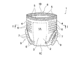
- FIG. 2 is a perspective view schematically showing a pants-type disposable diaper of the basic technology manufactured by carrying out the manufacturing method shown in FIG.
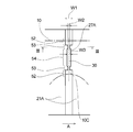
- FIG. 3 is a cross-sectional view schematically showing a cross section taken along line II of FIG.
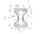
- FIG. 4 is a plan view schematically showing a developed and extended state of the diaper shown in FIG.
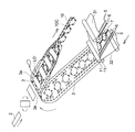
- FIG. 5 is a perspective view schematically showing a manufacturing process of the diaper continuous body shown in FIG. 1.
- FIGS. 7 (a) and 7 (c) are diagrams schematically showing a state where the diaper continuous body is introduced into the laser-type bonding apparatus shown in FIG. 1 in a plane
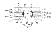
- FIG. FIG. 6B is a cross-sectional view taken along the line II-II of FIG. 6A.
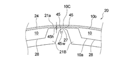
- FIGS. 7 (a) to 7 (c) show the side seal portion (seal edge) at the same time that the continuous diaper (strip-shaped exterior body) is cut using the laser type bonding apparatus shown in FIG. It is explanatory drawing explaining a mode that it forms.
- FIG. 8 is a view corresponding to FIG. 7C of another example of a method for manufacturing a pants-type disposable diaper using the laser-type bonding apparatus shown in FIG.
- FIG. 9 (a) and 9 (b) are respectively a side seal portion (seal edge portion) on one side and the vicinity thereof in FIG. 3 in a state where the waist opening of the diaper shown in FIG. 3 is expanded.
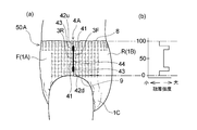
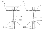
- Fig.10 (a) is a side view of 1st Embodiment (pants-type disposable diaper) of the underpants type wearing article of this invention
- FIG.10 (b) is the seal edge part of the side seal part of 1st Embodiment. It is a graph which shows distribution of the fusion strength of.
- FIG. 11 is a view corresponding to a partially enlarged view of FIG. 6A in the first embodiment of the manufacturing method of the present invention.
- FIG. 12A is a graph showing the relationship between the width of the slit (light passage portion), the fusion strength of the seal edge, and the seal width.
- FIG. 12B is a schematic diagram showing how the pressurization state of the target portion irradiated with laser light changes when the width of the slit (light passage portion) is changed.
- FIG. 12C is an explanatory diagram of the seal width.
- FIG. 13 is a schematic cross-sectional view showing a laser beam passage and its vicinity in the laser-type bonding apparatus used in the second embodiment of the manufacturing method of the present invention.
- FIG. 14 is a view showing a state in which the light passage portion of the laser beam and the vicinity thereof in the laser type bonding apparatus shown in FIG.
- FIG. 13 are viewed from the outer surface side of the cylindrical roll on which the diaper continuous body (band-shaped exterior body) is arranged. is there.
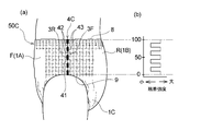
- Fig.15 (a) is a side view of 2nd Embodiment (pants-type disposable diaper) of the underpants type wearing article of this invention
- FIG.15 (b) is the seal edge part of the side seal part of 2nd Embodiment. It is a graph which shows distribution of the fusion strength of.
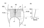
- FIG.16 (a) is a side view of 3rd Embodiment (pants-type disposable diaper) of the underpants type wearing article of this invention
- FIG.16 (b) is the seal edge part of the side seal part of 3rd Embodiment. It is a graph which shows distribution of the fusion strength of.
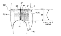
- Fig. 17 (a) is a side view of the fourth embodiment (pants-type disposable diaper) of the pants-type wearing article of the present invention
- Fig. 17 (b) is a seal edge of the side seal portion of the fourth embodiment. It is a graph which shows distribution of the fusion strength of.
- Fig.18 (a) is a side view of 5th Embodiment (pants type disposable diaper) of the underpants type wearing article of this invention
- FIG.18 (b) is a seal edge of the side seal part of 5th Embodiment. It is a graph which shows distribution of the fusion strength of.
- FIG.19 (a) is a side view of 6th Embodiment (pants-type disposable diaper) of the underpants type wearing article of this invention
- FIG.19 (b) is a seal edge of the side seal part of 6th Embodiment. It is a graph which shows distribution of the fusion strength of.
- FIG. 20A is an explanatory diagram of a preferable manufacturing method of the diaper of the fourth embodiment (corresponding to FIG. 11)
- FIG. 20B is an explanatory diagram of a preferable manufacturing method of the diaper of the fifth embodiment ( FIG. 11 is a diagram corresponding to FIG.
- the present invention relates to a pants-type wearing article having a side seal portion excellent in flexibility or touch, and excellent in ease of tearing and feeling of tearing, and a method for manufacturing the same.
- One of the main features of the present invention includes an exterior body that forms an outer surface of a worn article, and a pair of side seals in which both side edges of the exterior body in the front body and both side edges of the exterior body in the back body are joined.
- a pant-type wearing article in which a waist opening and a pair of leg openings are formed, the side seal part is the edge of the exterior body in the front body and the edge of the exterior body in the back body is the side seal
- a device for improving the ease of tearing and the tearing feeling on the seal edge hereinafter improved tearability
- this tearability improving means is, for example, by irradiating a laser beam to a predetermined portion of the belt-shaped exterior body in a state where the front body side and the back body side are overlapped in the manufacturing process of the pants-type wearing article, When the outer body is divided into lengths for individual wearing articles, and at the same time, the cut edges of the laminated outer body produced by the division are fused together to form a pair of side seal parts. It is particularly useful.
- FIG. 1 The outline of the manufacturing method of the underpants type disposable diaper using the laser type
- a diaper 1 that is a manufacturing object of a manufacturing method using this laser type bonding apparatus includes an absorbent main body 2 and an exterior body 3 that forms the outer surface of a wearing article.
- a pants-type disposable diaper in which B1 and B1 are joined to form a pair of side seal portions 4 and 4, a waist opening 8 and a pair of leg openings 9 and 9.
- the exterior body 3 is positioned on the non-skin contact surface side of the absorbent main body 2 and fixes the absorbent main body 2.
- the pair of side seal portions 4, 4 in the diaper 1 extends in the longitudinal direction of the side seal portion 4, with the edge of the exterior body 3 in the front body F and the edge of the exterior body 3 in the back body R, respectively.
- the sealing edge part 41 couple
- the diaper 1 has a longitudinal direction X corresponding to the wearer's front-rear direction and a lateral direction Y orthogonal to the wearer's front-rear direction in a developed and extended plan view as shown in FIG.
- the diaper 1 can be divided into a crotch part 1C arranged at the crotch part at the time of wearing, and an abdominal side part 1A and a back side part 1B located in the longitudinal direction X.
- the exterior body 3 in the crotch part 1 ⁇ / b> C is formed with recesses for forming leg openings 9, 9 at the left and right side edges along the vertical direction X.
- the diaper 1 can be divided into a front body F and a back body R with a virtual center line CL that bisects the diaper 1 in the vertical direction X as a boundary.
- a skin contact surface is a surface directed to a wearer's skin side at the time of wearing in a pants type wearing article or its constituent member (for example, an absorptive main part), and a non-skin contact surface is In the pants-type wearing article or its constituent members, it is a surface directed to the side opposite to the wearer's skin side (clothing side) when worn.
- the vertical direction X corresponds to the direction (longitudinal direction) along the long side of the absorbent main body 2 which is a disposable diaper or its constituent member
- the horizontal direction Y is the absorbent which is a disposable diaper or its constituent member. It coincides with the width direction of the main body 2.
- the absorbent main body 2 has a vertically long shape in one direction (longitudinal direction X), and a surface sheet (not shown) that forms a skin contact surface; A back sheet (not shown) that forms a non-skin contact surface, and a liquid-retaining absorbent (not shown) interposed between the two sheets. And has a long shape in the same direction.
- the absorbent main body 2 is joined to a central portion of the outer package 3 by a known joining means (adhesive or the like) so that the longitudinal direction thereof coincides with the longitudinal direction X of the diaper 1 in the unfolded and extended state.
- the expanded and extended state means that the side seal portion is peeled off, the diaper is set in the expanded state, the elastic member of each part is expanded in the expanded diaper, and the design dimensions (the influence of the elastic member is eliminated at all). In this state, it is expanded until it becomes the same size as when expanded in a flat shape.
- the outer package 3 is arranged on the outer layer sheet 31 that forms the outer surface of the diaper 1 (non-skin contact surface of the outer package 3), and on the inner surface side of the outer layer sheet 31.
- An inner layer sheet 32 that forms the inner surface of 1 (skin contact surface of the exterior body 3), and a plurality of thread-like or belt-like elastic members 5, 6, and 7 fixed between the sheets 31 and 32 with an adhesive. It is configured to include.
- the two sheets 31 and 32 are joined to each other at a predetermined site by an adhesive or heat seal (not shown).
- the exterior body 3 (the outer layer sheet 31 and the inner layer sheet 32) includes a resin material and is formed using the resin material as a main component.
- the resin material includes a heat-sealable synthetic resin such as polyethylene, polyethylene terephthalate, and polypropylene.
- the nonwoven fabric include air-through nonwoven fabric, heat roll nonwoven fabric, spunlace nonwoven fabric, spunbond nonwoven fabric, and melt blown nonwoven fabric.
- the manufacturing method of the diaper 1 exists in the superposition
- polymerization pressurization process which makes the formation planned site
- the belt-shaped outer package 3 (outer layer sheet 31, inner layer sheet 32) is folded in the width direction.
- the front body side and the back body side of the strip-shaped exterior body 3 to which the absorbent main body 2 is fixed are overlapped with each other, whereby “a precursor of a pants-type disposable diaper in which a side seal portion is not formed is unidirectional.
- a continuous diaper 10 is produced.
- sticker part formation process as shown in FIG. 1, the strip
- the pants comprising the exterior body 3 having a pair of side seal portions 4 and 4 by fusing the cut edges of the plurality of exterior bodies 3 (the outer layer sheet 31 and the inner layer sheet 32) in a laminated state generated by The mold disposable diaper 1 is continuously manufactured.
- the waist elastic member 5 forming the waist gather, the waist elastic member 6 forming the waist gather, and the leg elastic member 7 forming the leg gather have a predetermined elongation rate.
- a plurality of each are arranged in the stretched state.
- the leg elastic member 7 is arranged while forming a predetermined leg-circumferential pattern via a known swing guide (not shown) that reciprocates perpendicular to the sheet flow direction.
- an adhesive coating machine (see FIG. (Not shown) to apply hot melt adhesive.
- the elastic members such as the waist elastic member 5 and the waistline elastic member 6 are divided by the laser light irradiation in the sheets 31 and 32 (the site where the side seal portion 4 is to be formed, reference numeral 10C in FIG. 6).
- an adhesive is preferable to apply an adhesive to the adhesive.
- a hot melt adhesive is intermittently applied to the waist elastic member 5 and the waist elastic member 6 by an adhesive application machine (not shown) before being arranged between the sheets 31 and 32. May be.
- a plurality of joint portions for joining the belt-like outer layer sheet 31 and the belt-like inner layer sheet 32 between the two adjacent waistline elastic members 6 and 6, It is also preferable to use a convex roll and a corresponding joining means (not shown) such as an anvil roll.
- the plurality of waistline elastic members 6 and the plurality of leg portions are made by using elastic member precut means (not shown) so as to correspond to positions where the absorbent main body 2 described later is disposed.
- the elastic member 7 is pressed and divided into a plurality of pieces so that the contraction function is not expressed.
- the elastic member precut means include an elastic member dividing portion used in the method for manufacturing a composite elastic member described in JP-A-2002-253605.
- an adhesive such as a hot melt adhesive is applied in advance to the absorbent main body 2 manufactured in a separate process (not shown), and the absorbent main body 2 is rotated by 90 degrees. Then, it is intermittently supplied and fixed on the inner layer sheet 32 constituting the strip-shaped outer package 3.
- the adhesive for fixing the absorbent main body may be preliminarily applied not to the absorbent main body 2 but to the position where the absorbent main body 2 is arranged in the inner layer sheet 32.
- leg hole LO ' is formed inside the annular part enclosed by the leg part elastic member 7 in the strip
- This leg hole forming step can be carried out by using a technique similar to that in a conventional method for manufacturing this type of article, such as a rotary cutter and a laser cutter.
- the leg hole is formed after the absorbent main body 2 is arranged on the belt-shaped outer package 3, but the leg hole may be formed before the absorbent main body 2 is arranged.
- the strip-shaped exterior body 3 is folded in the width direction (a direction perpendicular to the conveying direction of the exterior body 3). More specifically, as shown in FIG. 5, both side portions 3 a, 3 a along the transport direction of the strip-shaped exterior body 3 are folded back so as to cover both ends in the longitudinal direction of the absorbent main body 2. After fixing both ends in the longitudinal direction, the outer package 3 is folded in the width direction together with the absorbent main body 2 (polymerization step in the polymerization pressure step). In this way, the diaper continuous body 10 is obtained.
- the diaper continuous body 10 thus manufactured is irradiated with laser light using a laser bonding apparatus 20 to form a pair of side seal portions 4 and 4 (side seal portion).
- a pants-type disposable diaper 1 having an exterior body 3 having a pair of side seal portions 4 is continuously manufactured.
- the laser type bonding apparatus 20 will be described.
- the laser type bonding apparatus 20 is arranged in a hollow cylindrical roll 23 that is rotationally driven in the direction of arrow A and a hollow portion of the cylindrical roll 23 as shown in FIG.
- a belt-type pressure device 26 including an irradiation head 35 that irradiates a laser beam 30 toward a cylindrical (annular) support member 21 that forms a peripheral surface portion 23, and an endless pressure belt 24 (pressing member).
- the laser-type joining device 20 includes a tension adjusting mechanism (not shown) that can adjust the tension of the pressure belt 24 wound around the outer peripheral surface of the annular support member 21 (the peripheral surface portion of the cylindrical roll 23). By adjustment, the pressure applied to the diaper continuous body 10 (sheet laminated body) can be appropriately adjusted by the support member 21 and the pressure belt 24.
- the support member 21 forms a peripheral surface portion (contact portion with the workpiece) of the cylindrical roll 23, and is between a pair of annular frames 22, 22 that form both ends of the cylindrical roll 23 in the rotation axis direction. It is pinched and fixed.
- the support member 21 is made of a metal material such as iron, aluminum, stainless steel, or copper, or a material having heat resistance such as ceramics.
- the support member 21 has a light passage portion 27 through which laser light can pass. As shown in FIG. 1, FIG. 6A and FIG. 6B, the support member 21 has a slit-like opening 27 that penetrates the support member 21 in the thickness direction as a light passage portion. .
- the opening 27 has a rectangular shape in plan view, and the longitudinal direction of the opening 27 intersects with the conveyance direction A of the diaper continuous body 10 (band-shaped exterior body 3).
- a plurality of cylinders are formed at predetermined intervals in the circumferential direction of the cylindrical support member 21 so as to coincide with the direction parallel to the axial length direction of the rotation shaft (the direction indicated by the symbol X in FIG. 6A).
- the support member 21 allows the laser light to pass through the opening 27, but does not allow the laser light to pass (transmit) at portions other than the opening 27.
- a method of forming the opening 27 in the support member 21 1) etching, punching, laser processing, or the like at a predetermined position of the support member 21 made of a single annular member having the same length as the circumferential length of the annular frame 22. 2)
- the support member 21 is replaced with a single annular member, and a plurality of curved rectangular members are used as the support member 21, and the plurality of members are connected between the pair of frames 22, 22.
- a method of arranging the frame body 22 at a predetermined interval in the circumferential direction may be mentioned.
- the interval between two adjacent members forms a slit-shaped opening 27.
- the method 2) is used.
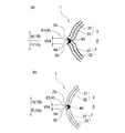
- a support member 21A in which the width of the opening 27A (light passage portion) changes in the longitudinal direction of the opening 27A (light passage portion).
- a projecting portion projecting toward the exterior body 3 is provided in the vicinity of the opening 27 (light passage portion) on the outer surface in contact with the strip-shaped exterior body 3.
- a support member 21 ⁇ / b> B in which the height of the protruding portion changes along the longitudinal direction of the opening (light passage portion).
- each of these members is the cylindrical shape of the cylindrical roll 23. It is rotationally moved in a curved state corresponding to the peripheral surface portion.
- a light passage portion through which laser light can pass is a support member.
- the parting portion 10C that overlaps with the opening 27 itself is not sandwiched between the members 21 and 24, but the vicinity thereof, that is, the portion that overlaps with the vicinity of the opening 27 (opening edge) in the diaper continuous body 10. Is sandwiched between the two members 21 and 24, and therefore does not move before and after the irradiation of the laser beam, and therefore, the cutting edge portion generated by the division of the diaper continuous body 10 by the irradiation of the laser beam does not move. That is, the parting planned portion 10C of the diaper continuous body 10 (portion overlapping the opening 27 in the sheet laminate) is a portion restrained by the pressing force between the members 21 and 24, and the pressing force is practically the same. It is an affected part.
- the support member 21 has a recess 28 on its outer surface (contact surface with the workpiece).
- a plurality of recesses 28 are formed at predetermined intervals in the circumferential direction of the cylindrical support member 21, and a slit-shaped opening 27 is formed in a region (convex part) located between two adjacent recesses 28, 28. Is formed.
- the opening 27 is formed in the center in the circumferential direction of the cylindrical support member 21 in the convex portion.
- the relative thickness of the diaper continuous body 10 is relatively small. It is possible to introduce the diaper continuous body 10 onto the outer surface of the support member 21 so that a large portion (for example, an arrangement region of the absorbent main body 2) is accommodated in the recess 28. Then, when the diaper continuous body 10 is introduced onto the support member 21 in such a manner, as shown in FIG. 6B, the contact surface (the other surface) of the diaper continuous body 10 with the pressure belt 24 (pressing member).
- the belt-type pressure device 26 includes an endless pressure belt 24 (pressing member) and three rolls 25a, 25b, and 25c that rotate while the pressure belt 24 is stretched.
- the rolls 25a, 25b, and 25c may be drive rolls or driven rolls that rotate with the pressure belt 24.
- the pressure belt 24 moves at the same speed as the cylindrical roll 23 (supporting member 21) by using any one or more of the rolls 25a, 25b, and 25c as a driving roll or rotating with the cylindrical roll 23.
- the support member 21 and the pressure belt 24 are preferably maintained in a predetermined temperature range by air cooling, water cooling, or the like.
- a metal or resin belt having heat resistance capable of withstanding the heat generated during processing can be used, for example, a metal material such as iron, aluminum, stainless steel, or the like. Can be used.
- a belt that does not transmit the laser beam irradiated to the workpiece strip-shaped outer package 3 is usually used. You can also.
- an irradiation head 35 that irradiates a laser beam 30 toward a support member 21 that forms a peripheral surface portion of the cylindrical roll 23 is provided in the hollow portion of the hollow cylindrical roll 23.
- the irradiation head 35 is a galvano scanner (device having a mirror on the motor shaft) that freely scans the laser light 30, and the laser light 30 is in a direction parallel to the rotation axis of the cylindrical roll 23 (reference numeral in FIG. 6A).
- a mechanism for making the spot diameter of the laser beam 30 constant is provided.
- the laser irradiation mechanism has such a configuration, so that the irradiation point of the laser light 30 is the circumferential direction of the cylindrical roll 23 and a direction orthogonal to the circumferential direction (a direction indicated by a symbol X in FIG. 6A). It can be arbitrarily moved in both directions of a direction parallel to the rotation axis of the roll 23).
- the diaper continuous body 10 includes a support member 21 that forms a peripheral surface portion of a cylindrical roll 23 that is rotationally driven in the direction of arrow A in a state where a predetermined tension is applied by a guide roll (not shown). After being transported by a predetermined distance in the circumferential direction by rotation of the cylindrical roll 23 so as to be wound around the support member 21, it is separated from the support member 21 by an unillustrated lead roll, nip roll or the like. . As described above, the diaper continuous body 10 is wound around the support member 21 forming the peripheral surface portion of the cylindrical roll 23 with a predetermined tension and is conveyed so as to be in pressure contact with the pressure belt 24.
- the portion sandwiched between the support member 21 and the pressure belt 24 and the vicinity thereof are in a state of being pressurized (compressed) in the thickness direction from before being divided by the laser light irradiation.
- the diaper continuous body 10 contains a nonwoven fabric, the diaper continuous body 10 can be more efficiently compressed, and as a result, the diaper continuous body 10 being compressed is irradiated with laser light.
- this it becomes possible to fuse the cut edges of the plurality of sheets (exterior body 3) constituting the divided portion more reliably, and the side seal portion 4 can be fused. The strength is improved.
- the rotation angle of the support member 21 (cylindrical roll 23) from when the diaper continuous body 10 is introduced onto the support member 21 to when the diaper continuous body 10 leaves the diaper continuous body 10 can be, for example, 90 degrees or more and 270 degrees or less. Is 120 degrees or more and 270 degrees or less.
- the range of the angle (pressure contact angle) at which the diaper continuous body 10 is pressed against the support member 21 by the pressure belt 24 (pressing member) is the entire circumference of the cylindrical support member 21 (cylindrical roll 23). When the pressure contact is 360 degrees, it is preferably 90 degrees or more and 270 degrees or less, and more preferably 120 degrees or more and 270 degrees or less.
- one surface 10a forms the peripheral surface portion of the cylindrical roll 23 and laser light.
- a continuous diaper brought into contact with the outer surface of the support member 21 having a slit-like opening 27 (light passage portion) through which 30 can pass and brought into a pressurized state by the support member 21 and the pressure belt 24 (pressing member).
- the body 10 part where the side seal portion 4 is to be formed
- the diaper continuous body 10 is divided at the same time.
- the cut edges of the plurality of sheets (exterior body 3) in the pressurized state are fused together to form the side seal portion 4 (side seal portion forming step).
- FIG. 7 is a diagram for explaining how the side seal portion 4 (seal edge) is formed at the same time as the diaper continuous body 10 (band-shaped sheet laminate) is divided using the laser bonding apparatus 20.
- 7 (a) schematically shows a portion 10C (part where the side seal portion 4 is to be formed) scheduled to be divided by the laser beam 30 of the diaper continuous body 10 and its vicinity.
- the diaper continuous part 10C of the diaper continuous body 10 in the illustrated embodiment is the center in the longitudinal direction (conveying direction A) in the region where the absorbent main body 2 of the diaper continuous body 10 is not disposed. It is. 10 C of such parting plan parts are the opening edge part of the waist opening part 8 (refer FIG.
- the 8 layer structure part on which 8 sheets were piled up, and other parts are 4 sheets. It is a four-layer structure part that is superimposed.
- the four-layer structure portion includes two sheets (an outer layer sheet 31 and an inner layer sheet 32) constituting one exterior body 3 in the ventral side part 1A, and a back side part 1B. It consists of the same two sheets 31 and 32 that constitute one exterior body 3, and these four sheets are laminated.
- the eight-layer structure portion is folded so that both side portions 3a and 3a of the strip-shaped outer package 3 cover both longitudinal ends of the absorbent main body 2 when the diaper continuous body 10 is manufactured ( (See FIGS.
- the sheets (inner layer sheet 32) absorb the laser beam 30 and generate heat.
- all of the four sheets 31 and 32 constituting the parting planned portion 10 ⁇ / b> C are sheets (nonwoven fabrics) that absorb the laser beam 30 and generate heat.
- the two sheets of the outer layer sheet 31 and the inner layer sheet 32 that overlap each other in the vicinity of the portion 10C to be divided may be joined by an adhesive or the like before the irradiation with the laser beam 30, or may be joined at all. It is not necessary.
- the diaper continuous body 10 has one surface 10 a abutting against the support member 21, and a parting planned portion 10 ⁇ / b> C (part where the side seal portion 4 is to be formed) is on the slit-shaped opening 27.
- the pressure belt 24 pressing member
- the pressure belt 24 is pressed against the other surface 10b so that it is conveyed in the direction of the arrow A while being introduced onto the support member 21 that rotates in the direction of the arrow A so as to be positioned in the direction of the thickness A.
- Pressure compression
- the laser beam 30 is irradiated through the opening part 27 from the supporting member 21 side with respect to the parting part 10C to be divided in such a conveyance and pressurization state.
- the irradiation point of the laser beam 30 is configured to be arbitrarily movable in the circumferential direction of the cylindrical roll 23, and is set to scan following the movement of the opening 27 along the circumferential direction. Therefore, the laser beam 30 is continuously irradiated for a certain period of time to the parting planned portion 10C located on the opening 27 during the conveyance.
- the forming materials (fibers, etc.) of the sheets 31 and 32 existing in the parting portion 10C are vaporized by the heat generated by the direct irradiation of the laser light 30 and disappear.
- the forming material existing in the vicinity of the parting portion 10 ⁇ / b> C is indirectly heated by the laser beam 30 and melted.
- the parting plan part 10C of a four-layer structure is melted, and in a form in which a single sheet sheet laminate (diaper precursor) is cut from the diaper continuous body 10,
- the cut edges of the four sheets 31 and 32 in the sheet laminate of the single sheets produced by the division, and the diaper continuous 10 are fused together.
- Each of these cut edges is pressed (compressed) by being sandwiched between the support member 21 and the pressure belt 24 from before the formation (before the diaper continuous body 10 is divided by irradiation with the laser beam 30). ).
- the strip-shaped exterior body 3 is divided by the single laser light irradiation, and the exterior body 3 in the two pressurized states generated by the division is thus obtained.
- the fusion and separation are the same with approximately half the laser output compared to the method of fusing the two fusion places with two laser irradiations. It can be carried out in a process, and the diaper 1 can be manufactured efficiently.
- the cut edges of the sheets 31 and 32 are heated and melted during the irradiation of the laser beam 30 and immediately after the end of the irradiation, but are separated from the diaper continuous body 10 by the irradiation of the laser beam 30.
- Each of the leaf diaper precursor and the diaper continuum 10 is maintained in the pressurized state by the support member 21 and the pressure belt 24, and after the irradiation is completed, the air is applied to the outside air, the support member 21 and the pressure belt 24.
- the material is quickly cooled and solidified by heat transfer to form the fused portion 40 in which the forming material (fibers, etc.) of the cut edge is fused and integrated.
- the fused part 40 one of the pair of side seal parts 4, 4 in one diaper 1 is formed.
- the cutting edge portions of the sheets 31 and 32 may be forcibly cooled by using known cooling means such as a suction device and an exhaust device to promote the formation of the fused portion 40.
- the laser beam 30 seems to hit another opening 27 adjacent to the irradiation direction in the direction opposite to the conveyance direction A. And is irradiated to another parting planned portion 10C located thereabove through the other opening 27.
- another part 10C to be divided is divided and fused in the same manner as described above, and the other side seal part 4 (fused part 40) that forms a pair with the previously formed side seal part 4 is formed.
- the pants-type disposable diaper 1 including the exterior body 3 having the pair of side seal portions 4 and 4 is continuously manufactured.
- the diaper is larger than the width W of the slit-shaped opening 27 irradiated with the laser beam 30 (see FIG. 7B.
- the portion 27 may be located at a portion sandwiched between a pair of opening edges along a direction orthogonal to the conveyance direction A. That is, in the diaper continuous body 10, even in a portion that is not sandwiched between the support member 21 and the pressure belt 24 (pressing member), in the vicinity of the opening 27 (opening edge), that is, as described above, The fused part 40 can be formed if the pressure applied by the clamping between the members 21 and 24 is practically affected.
- the side seal portion 4 includes an edge portion 3F of the outer body 3 in the front body F and an edge portion 3R of the outer body 3 in the rear body R.
- the sealing edge part 41 couple
- the seal edge 41 has an outer edge 4a composed of the fused portion 40 in the cross section orthogonal to the direction in which the side seal portion 4 extends when worn. It has a shape recessed toward the inside.
- the fused portion 40 in the seal edge portion 41 has a narrow width W4 that appears on the outer surface of the diaper in the same cross section, and the width W4 is preferably 5 mm or less, more preferably 3 mm or less, and even more preferably 2 mm or less. It is.
- bond part 40 of the seal edge part 41 in this invention has the constant width W4 which appears on the outer surface of a pants
- the width W4 appearing on the outer surface of the pants-type wearing article is constant over the entire length in the longitudinal direction of the side seal part 4 and the maximum value of the width W4 in the entire range in the longitudinal direction of the side seal part 4 It means that the difference from the minimum value of the width W4 is less than 50% of the maximum value.
- the production method of the present invention there is an advantage that the fusion strength can be increased or decreased while maintaining the width W4 substantially constant and maintaining good flexibility and touch.
- the width W4 is narrow as described above. Considering the size of the entire product, even if the width W4 of the side seal portion 4 is swung by 50%, the width W4 is substantially narrow and has the above-described fusion strength and appearance. .
- the direction where the side seal part 4 is extended is extended.
- the side seal part 4 (seal edge part 41) generated by the above-mentioned division in the cross section in the direction perpendicular to the horizontal direction (the same direction as the lateral direction Y of the diaper 1) is the outer edge 4a formed by the outer edge of the fused part 40.
- a fusion arcuate portion 40 of the four sheets 31 and 32 constituting the outer package 3 is formed on the inner side of the diaper 1 including the outer edge 4a and more on the inner side of the diaper 1 than the outer arc 4a.
- the fusion part 40 is formed, and the center part in the thickness direction of the exterior body 3 (the vertical direction in FIG. 7C or FIG. 8) is wider than the both end parts (upper end part and lower end part). . More specifically, the fusion part 40 has a width of the fusion part 40 toward the center part in the thickness direction in a cross-sectional view along the lateral direction Y of the diaper 1 (direction orthogonal to the dividing direction by the laser beam). It gradually becomes wider and is formed in a so-called crescent or half-moon shape (the fused portion 40 shown in FIG. 7 (c) has a crescent shape). It is preferable that the seal edge part 41 has such a shape even in a worn state.
- the side seal portion 4 is harder and softer than other parts of the diaper 1 due to the presence of the fused portion 40 formed by melting and solidifying the sheet forming material, and causes the feeling of wearing the diaper 1 to be reduced.
- the fusion part 40 is formed in a crescent shape or a half moon shape in a cross-sectional view in the width direction of the diaper 1 as described above, the fusion part in the conventional side seal part (for example, in Patent Document 1) Compared to the case where it is formed in a rectangular shape in the same sectional view as shown in FIG. 1 (part indicated by reference numeral 9), the corner 3S of the side edge portion of the exterior body 3 constituting the side seal portion 4 is formed.
- the wearing feeling of the diaper is improved as compared with the conventional product.
- the central portion in the thickness direction of the side edge of the exterior body 3 (the corner 3S on the one surface side of the exterior body 3 and the 3S on the other surface side, which is a part that greatly affects the fusion strength of the side seal portion 4) Since a sufficient amount of the fused portion 40 exists in the center portion between the side portions), the side seal portion 4 has a practically sufficient fusion strength, and the side seal portion 4 is worn while the diaper 1 is worn. Inconveniences such as tearing of the seal 4 hardly occur.
- the side seal part 4 (fusion
- 9A and 9B show the side seal portion 4 (fused portion 40) in a state where the waist opening 8 is expanded when the diaper 1 is worn. In the state where the waist opening 8 is expanded, the side seal portion 4 is normally in a state where the fused portion 40 is exposed as shown in FIG. 9A, but the outer edge 4a of the side seal portion 4 is the exterior. It is difficult to visually recognize from the outside due to the convex arc shape toward the inside of the body 3 and the fact that the fused portion 40 is smaller than the conventional side seal portion (fused portion).
- the outer edge 4a of the side seal portion 4 has a convex arc shape toward the inner side of the exterior body 3, so that depending on the forming material of the sheets 31, 32, as shown in FIG.
- the corner 3S of the side edge of the exterior body 3 on the abdominal side 1A side and the corner of the side edge of the exterior body 3 on the back side 1B side The portion 3S may approach and the separation distance between the corner portions 3S and 3S may be reduced. Therefore, the fusion part 40 located between the two corners 3S and 3S is difficult to touch by the hand and is located on the outer side of the diaper 1 closer to the diaper 1 than the fusion part 40. Therefore, not only the feeling of wearing the diaper 1 but also the appearance is improved.
- the laser beam irradiated to the diaper continuous body 10 is absorbed by the sheets (the outer layer sheet 31 and the inner layer sheet 32) constituting the outer package 3 to generate heat.
- a laser beam having a wavelength is used.
- the “sheet constituting the exterior body” is not limited to the sheet (for example, the outer layer sheet 31 in the above-described embodiment) constituting one surface of the exterior body (the contact surface with the support member 21). Any sheet may be used as long as the sheet is configured. Whether or not the laser light applied to the exterior body has an oscillation wavelength that is absorbed by the sheet and generates heat for the individual sheets constituting the exterior body depends on the material of the sheet and the laser light to be used.
- the laser beam may be CO 2 laser, YAG It is preferable to use a laser, an LD laser (semiconductor laser), a YVO4 laser, a fiber laser, or the like.
- the oscillation wavelength that can be absorbed by the sheet and cause the sheet to generate heat is, for example, 8.0 ⁇ m or more and 15 It is preferable to use 0.0 ⁇ m or less, and it is particularly preferable to use an oscillation wavelength of 9.0 ⁇ m or more and 11.0 ⁇ m or less of a CO 2 laser in which a high-power laser device exists.
- the spot diameter of laser light, laser output, and the like can be appropriately selected in consideration of the material and thickness of the sheet constituting the exterior body.
- [Tearability improvement means] A pair of side seals 4 and 4 obtained through the process in which the diaper 1 which is the manufacturing object of the manufacturing method using the laser type bonding apparatus described above, that is, the division and welding of the outer package 3 are performed simultaneously.
- the diaper 1 which comprises is excellent in the softness
- the fusion strength tends to be uniform in the longitudinal direction of the side seal portion, and the ease of tearing and the feeling of tearing tend to be insufficient.
- the diaper 1 is provided with means for improving tearability for the purpose of enhancing the ease of tearing and the feeling of tearing.
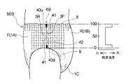
- FIG. 10 shows a first embodiment of the pant-type wearing article of the present invention (pants-type disposable diaper 50A).
- the pair of side seal portions 4A in the diaper 50A of the first embodiment is similar to the pair of side seal portions 4 in the diaper 1 described above, and the outer edge portion 3F of the outer body 3 in the front body F and the outer body 3 in the rear body R.
- the edge portion 3R forms a seal edge portion 41 joined by a continuous linear fusion portion 40 extending in the longitudinal direction of the side seal portion 4A.
- the structure and forming method of the seal edge 41 are the same as the seal edge 41 in the diaper 1 described above.
- the difference between the diaper 50A of the first embodiment and the diaper 1 described above is that, as shown in FIG.
- the seal edge portion 41 constituting the side seal portion 4A has a weakly bonded region 42 having a relatively low fusion strength. And a high bonding region 43 having a relatively high fusion strength. “Relatively low” means “low” compared to the contrasting region, and “relatively high” means “high” compared to the contrasting region.
- the width W4 of the fused portion 40 appearing on the outer surface of the diaper is the same over the entire length in the longitudinal direction of the side seal portion (seal edge portion). However, for convenience of explanation, the width of the side seal portion (seal edge portion) is changed to a width corresponding to the strength of the fusion strength. That is, the lower the fusion strength, the narrower the width, and the thicker the higher the fusion strength.
- the fusion strength is the fusion strength between the outer body 3 on the front body F side and the outer body 3 on the rear body R side in the seal edge 41, and a preferable measurement method is as follows.
- ⁇ Measurement method of fusion strength> From the pants-type wearing article, the side seal part 4 is located in the center in the longitudinal direction, and has a width having a part of the outer body 3 on the front body F side and a part of the outer body 3 on the rear body R side on both sides thereof. A 10 mm strip-shaped test piece is cut out, and the test piece is fixed between chucks of a tensile tester (for example, Tensilon “RTC series” manufactured by A & D).
- a tensile tester for example, Tensilon “RTC series” manufactured by A & D.
- test piece is pulled at an extension speed of the interval between chucks of 300 mm / min until the outer body 3 on the front body F side and the outer body 3 on the rear body R side are completely divided in the longitudinal direction. .
- the maximum value of the tensile stress at that time is defined as the fusion strength.
- the seal edge 41 in the side seal portion 4A of the diaper 50A of the first embodiment has an end weakly bonded region 42u (weakly bonded region) having a relatively low fusion strength at the end on the waist opening 8 side.
- a high joint region 43 having a relatively high fusion strength is provided at a portion adjacent to the end weak joint region 42u.
- the side seal portion 4A is formed by forming the seal edge portion 41 similar to the seal edge portion 41 of the diaper 1, the side seal portion 4A has flexibility and touch. Is excellent. Moreover, since it has the edge part weak junction area
- the diaper 50A of the first embodiment has an intermediate joint region 44 having a fusion strength intermediate between the end weak joint region 42u and the high joint region 43 at the center in the longitudinal direction of the side seal portion 4A. ing.
- FIG. 10B is a graph showing the fusion strength of the seal edge at each position when the lower end position of the side seal portion is 0 and the upper end position is 100.
- an end weakly bonded region 42d (weakly bonded region) having a relatively low fusion strength is also provided at the end of the seal edge 41 on the side of the leg opening 9 in the side seal portion 4A. And also has a high bonding region 43 having a higher fusion strength than that of the end weakly bonded region 42d in the adjacent portion of the end weakly bonded region 42d in the longitudinal direction of the side seal portion 4A. Yes. Therefore, the side seal portion 4A can be easily torn from the leg opening 9 side, and the diaper (wearing article) removing operation can be performed smoothly.
- each region has the following fusion strength measured by the measurement method described above. It is preferable.
- the fusion strength at the end weakly bonded regions 42u and 42d is preferably 18 N / 10 mm or less, more preferably 15 N / 10 mm or less, preferably 1 N / 10 mm or more, more preferably 1.5 N / 10 mm. That's it.
- the fusion strength in the high bonding region 43 is preferably 2 N / 10 mm or more, more preferably 2.5 N / 10 mm or more, preferably 20 N / 10 mm or less, more preferably 18 N / 10 mm or less.
- the fusion strength in the intermediate bonding region 44 is preferably 1.5 N / 10 mm or more, more preferably 2 N / 10 mm or more, and preferably from the viewpoint that a bond that does not come off at the time of wearing and is easy to tear after use is required. It is 18 N / 10 mm or less, more preferably 15 N / 10 mm or less.
- the diaper 50A of the first embodiment is manufactured in the same manner as the manufacturing method described in the basic technique except that the support member 21A is used.
- the diaper continuous body 10 (band-shaped exterior body 3) in a state where the front body side and the back body side are overlapped is introduced into a cylindrical roll 23 having a peripheral surface portion made of a support member 21A.
- the opening 27A is formed with respect to the formation planned portion 10C of the side seal portion of the diaper continuous body 10 (band-shaped outer package 3) while applying pressure between the pressure belt 24 and the support member 21A.
- the laser beam 30 is irradiated. As shown in FIG.
- the opening 27 ⁇ / b> A (light passage portion) in the support member 21 ⁇ / b> A includes a wide portion 52, a narrow portion 53 that is narrower than the wide portion 52, and an intermediate portion between the wide portion 52 and the narrow portion 53.
- An intermediate width portion 54 having a width is provided.
- the “intermediate width” is a width wider than the narrow portion 53 and narrower than the wide portion 52.
- a corresponding cross-sectional view (a cross-sectional view taken along the line III-III in FIG. 11) in a portion irradiated with laser light through the narrow portion 53 appears in the same manner as FIG.
- the portion irradiated with the laser beam through the narrow portion 53 is subjected to the same process as the laser beam irradiation shown in FIG.
- the exterior body 3 is divided, and the cut edges of the laminated exterior body 3 are generated by the division.
- the portion 10C where the side seal portion is to be formed in the portion irradiated with laser light through the intermediate width portion 54 or the wide portion 52, the wider the width, the relatively less the pressure is applied.
- the laser beam 30 is irradiated to the diaper continuous body 10 in a state where the outer package of the sheet is not sufficiently adhered to the narrow portion 53.
- the outer body 3 is divided at the portion irradiated with the laser light through the intermediate width portion 54 or the wide portion 52, the melting of the cut edges of the laminated outer body 3 caused by the division occurs.
- the fusion strength by the fusion part 40 generated by the adhesion is weaker than that of the part irradiated with the laser light through the narrow part 53.
- FIG. 12A shows the following conditions while pressing with a laser-type bonding apparatus shown in FIG.
- FIG. 12B is a schematic diagram showing how the pressurization state of the target portion irradiated with laser light changes when the width of the slit (light passage portion) is changed.
- Laser light irradiation conditions Spot diameter: 0.3 mm Pressure: 0.4 MPa
- the width of the light passage part is excessively increased with respect to the spot diameter, the fusion strength becomes zero, and the edge of the exterior body in the front body before fusion and the edge of the exterior body in the back body are not joined. Part is generated. Accordingly, a support member in which such a relationship is obtained in advance for each laminated structure of the exterior body to be irradiated with laser light, and the width of the light passage portion is appropriately controlled according to the fusion strength to be applied to the seal edge portion. 11, for example, as shown in FIG. 11, the laser beam is emitted from the central portion of the slit-shaped opening 27 ⁇ / b> A from the one end side to the other end side in the axial length direction of the cylindrical roll.
- the diaper 50A can be manufactured only by scanning linearly at a constant speed without changing the output.
- the support member whose width of the light passage portion changes in the longitudinal direction of the light passage portion is used, and the laser beam is irradiated through the light passage portion, thereby providing flexibility and touch.
- the ratio (W2 / W1) of the width W2 of the narrow portion 53 to the width W1 of the wide portion 52 is, for example, preferably 0.025 or more, more preferably 0.05 or more, and preferably 0.9. Or less, more preferably 0.85 or less, and preferably 0.025 to 0.9, more preferably 0.05 to 0.85.
- the ratio (W3 / W1) of the width W3 of the intermediate width portion 54 to the width W1 of the wide portion 52 is, for example, preferably 0.05 or more, more preferably 0.075 or more, and preferably 0.95. Or less, more preferably 0.9 or less, and preferably 0.05 to 0.95, more preferably 0.075 to 0.9.
- FIG. 13 is an explanatory diagram of a second embodiment of the manufacturing method of the present invention for manufacturing the diaper 50A of the first embodiment.
- the exterior body 3 side is located in the vicinity of the opening 27 (light passage portion) in the outer surface 21a with which the strip-shaped exterior body 3 contacts.
- the support member 21 ⁇ / b> B has a protrusion 45 that protrudes in the height direction, and the height 45 h of the protrusion 45 changes discontinuously along the longitudinal direction of the opening 27 (light passage portion).
- the light passing portion through which the laser light can pass is composed of a slit-shaped opening 27 that penetrates the support member 21 in the thickness direction.
- the portion of the exterior body 3) that overlaps with the opening 27 does not generate pressure applied by being sandwiched between the support member 21 and the pressure belt 24 (pressing member). Since the portion 10 ⁇ / b> C is a portion in which the applied pressure is substantially affected, the fused portion 40 is formed. In order to form the fused portion 40 more stably, it is effective to further increase the pressure applied by the clamping between the members 21 and 24.
- a protruding portion 45 is formed on the outer surface 21a on the outer diaper continuous body 10 side (on the belt-shaped outer package 3 side and the pressure belt 24 side) with respect to the outer surface 21a. More specifically, the protrusion 45 is formed along each of a pair of opening edges extending in the longitudinal direction of each of the plurality of openings 27 (the width direction of the support member 21) on the outer surface 21 a of the support member 21. Each protrusion 45 is formed to extend in the longitudinal direction along the opening 27.
- Each protrusion 45 has a high-order part 45a, a low-order part 45b, and a middle-order part 45c having different protrusion heights 45h (projection heights from the peripheral part) in the longitudinal direction.
- the lower part 45b has a lower protrusion height 45h than the higher part 45a
- the middle part 45c has a protrusion height 45h higher than the lower part 45b and lower than the higher part 45a.
- the top of the protrusion 45 may be flat or a curved surface having a predetermined curvature, and the curved surface may be parallel to the outer surface 21 a of the cylindrical support member 21.
- a protruding part 45 having a high-order part 45a is formed, so that the diaper continuous body 10 (strip-shaped exterior body) is provided in the vicinity of the high-order part 45a. ) Can be effectively increased in the vicinity of the portion scheduled to be divided, thereby ensuring the division of the diaper continuous body 10 and the fusion of the cut end, and the above-described high bonding region in the seal edge portion 41. 43 can be formed reliably.
- the applied pressure in the vicinity of the part to be divided in the diaper continuous body 10 can be reduced as compared with the vicinity of the higher portion 45a.
- region 43 in the seal edge part 41 mentioned above can be formed efficiently.
- the support member 21B in which the protrusion height of the protrusion 45 changes along the longitudinal direction of the light passage portion 27 is pressed by the support member 21B.
- the protrusion height 45h (see FIG. 13) of the protrusion 45 is preferably 0. 0.1 mm or more, more preferably 1 mm or more, preferably 10 mm or less, more preferably 8 mm or less, preferably 0.1 mm or more and 10 mm or less, more preferably 1 mm or more and 8 mm or less.
- the width 45w of the protrusion 45 is preferably 1 mm or more, more preferably 2 mm or more, and preferably 20 mm or less, more preferably.
- the lower portion 45b has a height difference from the higher portion 45a of preferably 0.1 mm or more, more preferably 0.2 mm or more, and preferably 5 mm or less, more preferably 4 mm or less, more specifically preferably It is 0.1 mm or more and 5 mm or less, More preferably, it is 0.2 mm or more and 4 mm or less.
- the middle portion 45c has a height difference from the high portion 45a of preferably 0.05 mm or more, more preferably 0.1 mm or more, and preferably 4.5 mm or less, more preferably 3.5 mm or less.
- the lower portion 45b may be a portion that does not protrude from the outer surface 21a of the support member 21 at all, instead of the one that protrudes from the outer surface 21a of the support member 21.
- FIG. 15 is a figure which shows the underpants type disposable diaper as 2nd Embodiment of the underpants type wearing article of this invention.
- the seal edge portion 41 in the side seal portion 4B of the diaper 50B of the second embodiment has an end high joint region 43u (high joint region) having relatively high fusion strength at the end on the waist opening 8 side.
- a weakly bonded region 42 having a relatively low fusion strength is provided at a portion adjacent to the end highly bonded region 43u.
- “Weak bonding area” is synonymous with “low bonding area”.
- the side seal portion 4B is formed by forming the seal edge portion 41 similar to the seal edge portion 41 of the diaper 1, the side seal portion 4B is flexible and soft. Is excellent. Moreover, since it has the edge part high joining area
- the end high joint region 43d (high joint region) having a relatively high fusion strength is also provided at the end of the seal edge 41 on the side of the leg opening 9 in the side seal portion 4B.
- a weakly bonded region 42 having a relatively low fusion strength is provided adjacent to the end highly bonded region 43d. Therefore, it is possible to prevent unintended peeling of the side seal part from the end part on the leg opening 9 side during wearing of the side seal part 4A.
- the diaper (wearing article) removal operation can be performed smoothly.
- the strength preferably has a fusion strength equivalent to that of the intermediate joint region 44 in the diaper 50A, and the weak joint region 42 preferably has a fusion strength equivalent to that of the weak joint region 42 in the diaper 50A.
- the diaper 50B of the second embodiment corresponds to the light passing portion 27A corresponding to the end portion on the waist opening portion 8 side and the end portion on the leg opening portion 9 side in the manufacturing method of the first embodiment of the present invention described above. It is manufactured in the same manner as in the method of the first embodiment except that it is replaced with one having a relatively narrow narrow portion at a position where it has a relatively wide wide portion between the narrow portions. be able to.
- the diaper 50B of 2nd Embodiment is the manufacturing method of the 2nd embodiment of this invention mentioned above, the support member 21B, the edge part by the side of the waist opening part 8 in the vicinity of the light passage part 27, and leg opening It can be manufactured in the same manner as in the method of the second embodiment except that a high-order part 45a is provided at a position corresponding to the end part on the part 9 side and a low-order part 45b is provided between the high-order parts 45a. .
- FIG. 16 is a figure which shows the underpants type disposable diaper as 3rd Embodiment of the underpants type wearing article of this invention.
- a weak joint region 42 and a high joint region 43 having different fusion strengths are formed on the seal edge 41 constituting the side seal portion 4C.
- the portions 4C are alternately formed in the longitudinal direction, and a plurality of portions are formed.
- the seal edge portion 41 constituting the side seal portion 4C and the weakly bonded regions 42 and the high bonded regions 43 having different fusion strengths are alternately formed.
- they are alternately peeled off, and vibrations and the like are transmitted to the hand, so infant guardians, elderly people, caregivers, etc. fully realize that the side seal 4C has been torn. It is capable of tearing and is excellent in tearing.
- the light passing portion 27A is formed by alternately forming the narrow portions 53 and the wide portions 52 in the longitudinal direction. It can be manufactured in the same manner as the method of the first embodiment except that it is replaced. Further, in the diaper 50C of the third embodiment, in the manufacturing method of the second embodiment of the present invention described above, the support member 21B is light-transmitted between the high-order part 45a and the low-order part 45b in the vicinity of the light passage part 27. It can be manufactured in the same manner as in the method of the second embodiment except that one formed alternately along the longitudinal direction of the portion 27 is used.
- FIGS. 17 to 19 are views showing pants-type disposable diapers as fourth to sixth embodiments of the pants-type wearing article of the present invention.
- the diaper 50D of the fourth embodiment, the diaper 50E of the fifth embodiment, and the diaper 50F of the sixth embodiment have continuous fusion strength at the seal edge portions 41 constituting the side seal portions 4D, 4E, 4F, respectively.
- the seal edge portion 41 constituting the side seal portion 4D is the other end on the leg opening 9 side from the one end portion on the waist opening 8 side of the side seal portion 4D.
- the sealing edge portion 41 constituting the side seal portion 4E is located on the side of the waist opening 8 of the side seal portion 4E.
- the sealing edge portion 41 constituting the side seal portion 4F is after the fusion strength gradually decreases from one end portion on the side of the waist opening 8 of the side seal portion 4F toward the center portion.
- the fusion strength gradually increases from the central portion toward the other end on the leg opening 9 side.
- the width of the opening 27 is used instead of the support member 21 used in the manufacturing method of the basic technology described above.
- 20A shows a support member 21C that can be preferably used for manufacturing the diaper 50D of the fourth embodiment
- FIG. 20B shows a support member that can be preferably used for manufacture of the diaper 50E of the fifth embodiment. 21D was shown.
- a diaper (wearing article) is provided at the end of the side seal portion 41D on the leg opening 9 side of the seal edge portion 41D because the seal edge portion 41 has a weak fusion strength.
- the side seal portion 4D can be easily torn from the leg opening 9 side, and the diaper (wearing article) removal operation can be performed smoothly.
- the fusion strength is increased from the leg opening 9 side toward the waist opening 8 side, unintentional peeling of the seal edge extends over a wide range of the side seal part 4D during wearing, It is possible to prevent the diaper (wearing article) from slipping off or coming off.
- a region where the sealing strength of the seal edge 41 is weak is formed on the end of the seal opening 41 on the side of the waist opening 8 and the end of the leg opening 9 on the side seal 4E. Therefore, when removing the diaper (wearing article), the side seal portion 4E can be easily torn from the waist opening 8 side or the leg opening 9 side, and the diaper (wearing article) removal operation can be performed smoothly. Can do. Further, since the fusion strength at the longitudinal center portion of the side seal portion 4E is high, unintentional peeling of the seal edge extends over a wide range of the side seal portion 4E during wearing, and the diaper (wearing article) ) Can be prevented from falling off or coming off.
- the diaper 50F of the sixth embodiment can prevent unintended peeling of the side seal portion from the end on the waist opening 8 side or the end on the leg opening 9 side during wearing.
- the diaper (wearing article) removal operation can be performed smoothly.
- the side seal part 4 (fusion part 40) becomes difficult to visually recognize from the outside in the wearing state or the natural state (contracted state) of the diaper 1, for example, after the use of the diaper 1, the protection from the infant who is the wearer When a person (for example, a mother) removes the diaper, it is difficult to find the side seal portion 4, and there is a possibility that it takes time to remove the diaper 1.
- the color of the constituent member of the diaper 1 that traverses the side seal portion 4 is changed to the side seal portion as a means for solving such inconvenience due to the decrease in visibility of the side seal portion 4.
- the method of making it differ on the ventral side (front side) and back side (rear side) rather than 4 is mentioned.
- the waist part elastic member 5 or the sheet constituting the exterior body 3 is composed of the abdominal side part 1 ⁇ / b> A (front view) and the back side part 1 ⁇ / b> B (back view) of the diaper 1.
- a method of changing the color of the sheet 32 or the like is employed, the side seal portion 4 is positioned at the color switching portion, so that the visibility of the side seal portion 4 is further enhanced, and the occurrence of the inconvenience is further effectively prevented.
- the melting of the outer package using the heat source is not limited to the laser beam irradiation to the outer package, and as a non-contact heat source, infrared or halogen light may be used. It can also be carried out by thermocompression bonding of the exterior body using a known heat roll device or the like, or applying ultrasonic vibration to the exterior body using a known ultrasonic vibration device or the like.
- segmentation of an exterior body and formation of a junction part in the said side seal part formation process may be simultaneous, and may be divided after formation of a junction part.
- the pant-type wearing article of the present invention is scanned with laser light when irradiating laser light linearly along the longitudinal direction of the slit-shaped opening (light passage part) in the manufacturing method of the basic technology.
- it can be manufactured by appropriately changing the output of the irradiated laser beam or the scanning speed. For example, it is possible to form a seal edge in which a region irradiated with an increased output is a high joint region and a region irradiated with a weak output is a weakly bonded region.
- the seal edge where the scanning speed is slowed down and the part that gives a relatively large amount of energy is a high joint area, and the part that fastens the scanning speed and the part that gives a relatively small amount of energy becomes a weak joint area. It can also be formed.
- laser light is added to the part where the fusion strength is to be increased.
- Other parts of the seal edge may be irradiated in advance by irradiating the laser beam only on the part where the fusion strength is to be increased before the laser beam is irradiated or the laser beam is irradiated. It is possible to form a high bonding region having a higher fusion strength than the portion.
- the protrusion height of the protrusion is discontinuously along the longitudinal direction of the light passage in the vicinity of the light passage on the outer surface in contact with the exterior body.
- the portion where the laser beam is irradiated to the portion that is relatively strongly pressed by the narrow portion is formed as a portion where the fusion strength is relatively high, and the portion where the fusion strength is relatively high and the portion where the width is wide.
- the portion where the fusion-bonded portion is formed by irradiating the weakly pressurized portion with the laser beam is a region having a relatively low fusion strength.
- the strip-shaped outer package (sheet laminate) is a stack of four sheets as shown in FIG. 7A, or two, three, or five or more sheets. May be.
- the laser-type bonding apparatus 20 is provided with a mechanism for controlling the tension of the diaper continuous body 10. Also good.
- the exterior body 3 in the embodiment (mode) is not divided into the abdominal part 1A and the dorsal part 1B, but the abdominal part 1A, the crotch part 1C, and the dorsal part 1B.
- the exterior body in the present invention is not limited to such a continuous shape, and is, for example, the stomach side disposed on the wearer's stomach side (front side). It is divided
- seat member distribute
- the polymerization pressurizing step includes a front body side (a belt-like stomach side sheet member) of the belt-like exterior body to which the absorbent main body is fixed.
- a site where the side seal portion is to be formed in the belt-shaped exterior body having a configuration in which the back body side (band-shaped backside sheet member) is superimposed is brought into a pressurized state.
- Pants-type wearing articles such as pants-type disposable diapers with a split-type exterior body can also be divided into a crotch part and an abdominal side part and a back side part extending in front and rear thereof, and the abdominal sheet member is worn when worn It arrange
- seat member is distribute
- seat member are mutually joined in the right-and-left both sides of a pants type wearing article, and a pair of side seal part is formed.
- both side parts along the conveyance direction of each inner layer sheet 32 were folded back so as to cover both ends in the longitudinal direction of the absorbent main body 2, the width direction (longitudinal direction) of the band-shaped outer layer sheet 31 was more than the band-shaped inner layer sheet 32. Absorbs only the extension part of the outer layer sheet 31 that extends outward from the side edge of the inner layer sheet 32 when the sheets 31 and 32 are overlapped.
- the body 2 may be folded back so as to cover both ends in the longitudinal direction.
- the parting plan part 10C of the diaper continuous body 10 is a six-layer structure part in which the opening end part of the waist opening part 8 and its vicinity are overlapped with six sheets, and the other part is four sheets. Becomes a four-layer structure part.
- seat 32 do not need to be folded.
- the end portion on the waist opening 8 side and the end portion weakly bonded regions 42u and 42d on the end portion on the leg opening 9 side are provided, and a high bonding region is provided in the adjacent portion.
- end high joint regions are provided at both the end on the waist opening 8 side and the end on the leg opening 9 side, and the side seal portion is provided in the center in the longitudinal direction.
- the weak joint region is provided, the end high joint region may be provided only in one of the end portion on the waist opening 8 side and the end portion on the leg opening 9 side.
- the following three methods (1) to (3) are exemplified as a method for producing a pants-type wearing article, the following three methods can be implemented by arbitrarily combining two or more.
- (1) In the side seal portion forming step using a support member in which the width of the light passage portion changes discontinuously or continuously in the longitudinal direction of the light passage portion, the strength of the fusion strength is applied to the seal edge portion. How to form.
- the method (1) and the method (2) are combined to form a region having a relatively high fusion strength at the seal edge with both sides of the narrow portion of the light passage portion as a high-order portion, while passing the light. It is also possible to form a region having a relatively low fusion strength at the seal edge portion by setting both sides of the wide portion of the portion to a lower portion.
- pant-type wearing article in the present invention is not limited to a pant-type disposable diaper, and may be a pant-type sanitary napkin. It may be a diaper cover or the like that does not include
- the description omitted in one embodiment described above and the requirements of only one embodiment can be applied to other embodiments as appropriate, and the requirements in each embodiment can be appropriately changed between the embodiments. Can be substituted.
- An exterior body that forms the outer surface of the wearing article is provided, and a pair of side seal portions, a waist opening portion, and a pair of leg openings are formed by joining both side edges of the exterior body in the front body and both side edges of the exterior body in the back body
- a pants-type wearing article in which a part is formed The side seal portion includes a seal edge portion in which the edge portion of the exterior body in the front body and the edge portion of the exterior body in the back body are joined by a continuous linear fusion portion extending in the longitudinal direction of the side seal portion.
- the pants-type wearing article which is formed and has the sealing edge portion continuous over the entire length of the side seal portion and having a strength of fusion strength in its longitudinal direction.
- the exterior body includes an outer layer sheet that forms an outer surface of a worn article, an inner layer sheet that is disposed on the inner surface side of the outer layer sheet, and a plurality of thread-like or belt-like elastic members that are fixed between the two sheets with an adhesive.
- the underpants-type wearing article according to the above ⁇ 1> comprising: ⁇ 3> Between the outer layer sheet and the inner layer sheet, a waist elastic member that forms a waist gather, a waist elastic member that forms a waist gather, and a leg elastic member that forms a leg gather are stretched to a predetermined elongation rate.
- the underpants-type wearing article according to the above ⁇ 2> wherein a plurality of each are arranged in an extended state.
- the exterior body in the front body and the exterior body in the back body include a waist elastic member forming a waist gather or a waist elastic member forming a waist gather
- ⁇ 6> The pants-type wearing article according to any one of ⁇ 1> to ⁇ 5>, wherein the exterior body includes a nonwoven fabric, a film, or a laminate sheet of the nonwoven fabric and the film.
- a fusion portion between sheets constituting the exterior body is formed on the outer edge of the seal edge portion, and the fusion portion is in the thickness direction of the exterior body.
- the outer edge of the seal edge portion has a convex arc shape toward the inside of the wearing article, and includes the outer edge and is further inward of the wearing article.
- ⁇ 1> to ⁇ 6 wherein a fusion part between sheets constituting the exterior body is formed, and the fusion part is wider at the center in the thickness direction of the exterior body than both ends.
- the seal edge portion has an end weakly bonded region having a relatively low fusion strength at an end on the waist opening side or an end on the leg opening side, and in the longitudinal direction of the side seal portion.
- the pants-type wearing article according to any one of the above items ⁇ 1> to ⁇ 8> which has a high bonding region having a relatively high fusion strength at a site adjacent to the end weak bonding region.
- the seal edge portion in the side seal portion has an end weak joint region having a relatively low fusion strength at the end on the waist opening side, and the end weakness in the longitudinal direction of the side seal portion.
- the end portion of the side seal portion in the longitudinal direction of the side seal portion has a weakly bonded end portion at the end portion on the leg opening portion side of the seal edge portion, and has a relatively low fusion strength.
- the pants-type wearing article according to any one of the above items ⁇ 1> to ⁇ 10>, wherein the article has a high-bonding region at a site adjacent to the weak-bonding region, the fusion strength being higher than that of the end weak-bonding region. .
- the seal edge portion has an end high joint region having relatively high fusion strength at an end portion on the waist opening side or an end portion on the leg opening side, and in the longitudinal direction of the side seal portion.
- the pants-type wearing article according to any one of the above items ⁇ 1> to ⁇ 8>, which has a weakly bonded region having a relatively low fusion strength at the center.
- the seal edge portion in the side seal portion has an end high joint region having a relatively high fusion strength at the end on the waist opening side, and the end height in the longitudinal direction of the side seal portion.
- the pants-type wearing article according to any one of ⁇ 1> to ⁇ 8>, wherein the article has a weakly bonded region having a relatively low fusion strength at a site adjacent to the bonded region.
- the end portion on the leg opening side of the seal edge in the side seal portion also has an end high joint region with relatively high fusion strength, and the end height in the longitudinal direction of the side seal portion.
- ⁇ 16> The pants-type wearing article according to any one of ⁇ 1> to ⁇ 14>, wherein the sealing edge has a continuously changing fusion strength in a longitudinal direction thereof.
- the sealing edge portion constituting the side seal portion has a fusion strength that continuously decreases from one end portion on the waist opening side of the side seal portion toward the other end portion on the leg opening portion side, The pants-type wearing article according to ⁇ 16>.
- the seal edge portion constituting the side seal portion after the fusion strength gradually increases from the one end portion of the side seal portion on the waist opening side toward the center portion, then the other side on the leg opening portion side from the center portion.
- the pants-type wearing article according to ⁇ 16> wherein the fusion strength gradually decreases toward the end.
- the seal edge portion constituting the side seal portion is formed on the other side of the leg opening portion from the center portion after the fusion strength gradually decreases from one end portion of the side seal portion on the waist opening side toward the center portion.
- the pants-type wearing article according to ⁇ 16> wherein the fusion strength gradually increases toward the end.
- ⁇ 20> The pant mold according to any one of ⁇ 1> to ⁇ 15>, wherein the fusion part has a constant width that appears on the outer surface of the pant-type wearing article over the entire length of the side seal part in the longitudinal direction. Wearing articles.
- the fusion strength at the end weakly bonded region is preferably 18 N / 10 mm or less, more preferably 15 N / 10 mm or less, preferably 1 N / 10 mm or more, more preferably 1.5 N / 10 mm or more.
- the fusion strength in the high bonding region is preferably 2 N / 10 mm or more, more preferably 2.5 N / 10 mm or more, preferably 20 N / 10 mm or less, more preferably 18 N / 10 mm or less.
- the fusion strength in the intermediate joining region is preferably 1.5 N / 10 mm or more, more preferably 2 N / 10 mm or more, preferably 18 N / 10 mm or less, more preferably 15 N / 10 mm or less.
- the pant-type wearing article according to any one of the above items ⁇ 1> to ⁇ 24>, wherein the color of the constituent member of the pant-type wearing article is different between the ventral side and the back side than the side seal portion.
- the pants-type wearing article has a crotch portion arranged in the crotch portion when worn, and a ventral side portion and a back side portion located in the longitudinal direction of the crotch portion,
- the pants-type wearing article can be divided into a crotch part arranged in the crotch part at the time of wearing, and a ventral part and a back part located in the longitudinal direction of the crotch part,
- the pants-type wearing article according to any one of ⁇ 1> to ⁇ 26>, wherein the exterior body has an hourglass-like continuous shape extending from the abdominal side, the crotch part, and the back side.
- the pants-type wearing article can be divided into a crotch part arranged in the crotch part at the time of wearing, and a ventral part and a back part located in the longitudinal direction of the crotch part,
- the exterior body is divided into an abdominal sheet member disposed on the abdominal side part and a back sheet member disposed on the back side part, and the absorbent main body is bridged and fixed to both the sheet members.
- the pants-type wearing article according to any one of ⁇ 1> to ⁇ 27>.
- the width of the light passage portion is changed in the longitudinal direction of the light passage portion by using a support member that changes discontinuously or continuously, and the fusion strength strength of the seal edge portion is increased or decreased.
- the manufacturing method of the underpants type wearing article which forms.
- the light passage part is a method for producing a pants-type wearing article according to the above ⁇ 29>, wherein a narrow part and a wide part narrower than the wide part are alternately formed in the longitudinal direction.
- the light passage part in the support member has a wide part, a narrow part narrower than the wide part, and an intermediate width part having an intermediate width between the wide part and the narrow part.
- the seal edge generated by the laser beam can be obtained by scanning the laser beam having the same spot diameter and the same laser output at a constant speed along the longitudinal direction of the light passing portion and changing the width of the light passing portion.
- the ratio (W2 / W1) of the width W2 of the narrow portion to the width W1 of the wide portion is preferably 0.025 or more, more preferably 0.05 or more, and preferably 0.9 or less.
- the ratio (W3 / W1) of the width W3 of the intermediate width portion to the width W1 of the wide portion is preferably 0.05 or more, more preferably 0.075 or more, and preferably 0.95 or less. More preferably, it is 0.9 or less, preferably 0.05 to 0.95, more preferably 0.075 to 0.9, any one of the above ⁇ 29> to ⁇ 33> Manufacturing method of pants-type wearing articles.
- the side seal portion forming step there is a projecting portion projecting toward the exterior body side in the vicinity of the light passage portion on the outer surface in contact with the exterior body, and the projecting height or width of the projecting portion is that of the light passage portion.
- a method for manufacturing a pants-type wearing article wherein a strength of fusion strength is formed on the seal edge using a support member that changes discontinuously or continuously along a longitudinal direction.
- the protrusion is formed along each of a pair of opening edge portions extending in the longitudinal direction of the light passage portion, and is formed to extend in the longitudinal direction along the light passage portion. In the direction, the projecting height from the peripheral part has a high part, a low part and a middle part that are different from each other,
- the pants according to ⁇ 35> wherein the lower portion has a protruding height lower than that of the higher portion, and the middle portion has a protruding height higher than the lower portion and lower than the higher portion.
- the protrusion height of the protrusion is preferably 0.1 mm or more, more preferably 1 mm or more, preferably 10 mm or less, more preferably 8 mm or less, and preferably 0.1 mm or more and 10 mm or less, More preferably, it is 1 mm or more and 8 mm or less,
- the height difference between the low-order part and the high-order part is preferably 0.1 mm or more, more preferably 0.2 mm or more, and preferably 5 mm or less, more preferably 4 mm or less, more specifically preferably
- the height difference between the middle portion and the high portion is preferably 0.05 mm or more, more preferably 0.1 mm or more, and preferably 4.5 mm or less, more preferably 3.5 mm or less.
- the pant-type wearing article according to any one of the above ⁇ 35> to ⁇ 38>, which is preferably 0.05 mm to 4.5 mm, more preferably 0.1 mm to 3.5 mm.
- Production method. ⁇ 40> Using the support member in which the width of the protruding portion formed in the vicinity of the light passage portion changes discontinuously along the longitudinal direction of the light passage portion, the strength of the fusion strength is formed on the seal edge portion.
- the part where the laser beam is irradiated to the part that is relatively strongly pressed by the narrow part, and the part where the fused part is formed is relatively weak by the part where the fusion strength is relatively high and the part where the width is wide.
- the width 45w of the protrusion is preferably 1 mm or more, more preferably 2 mm or more, and preferably 20 mm or less, more preferably 10 mm or less, more specifically, preferably 1 mm or more and 20 mm or less, more preferably 2 mm or more.
- ⁇ 42> The method for producing a pants-type wearing article according to any one of the above ⁇ 1> to ⁇ 28>, A polymerization pressurizing step for pressing the formation planned site of the side seal part in the belt-shaped exterior body in a state where the front body side and the back body side are overlapped; and While cutting the exterior body by irradiating a laser beam through a light passage portion extending in a direction intersecting the transport direction of the exterior body to the formation planned site of the side seal portion in a pressurized state A side seal part forming step of forming the side seal part by fusing the cut edges of the laminated outer package produced by the division, In the said side seal part formation process, the manufacturing method of the underpants type wearing article which forms the strength of fusion strength in the said seal edge part by changing the output or scanning speed of the laser beam to irradiate.
- a waist gather is formed between the belt-like outer layer sheet constituting the outer package continuously supplied from the raw fabric roll and the belt-shaped inner layer sheet constituting the outer package continuously supplied from the raw roll.
- the manufacturing method of the underpants type wearing article of any one of 45>. ⁇ 47> By feeding and pressing a belt-like outer layer sheet and a belt-like inner layer sheet sandwiching a waist elastic member, a waistline elastic member, and a leg elastic member in a stretched state between a pair of nip rolls, a plurality of pieces are provided between the belt-like sheets.
- the belt-like outer layer sheet and the belt-like inner layer sheet constituting the exterior body are hot-melted with an adhesive coating machine on a predetermined portion of one or both of the opposite surfaces of the two sheets before being overlapped.
- the elastic member such as the waist elastic member, the waist elastic member, and the like in the band-shaped outer layer sheet constituting the outer package and the portion to be divided by the laser beam irradiation in the band-shaped inner layer sheet constituting the outer package
- the stretched state is arranged so as to straddle, the pants-type wearing article according to any one of the above items ⁇ 29> to ⁇ 48>, wherein an adhesive is applied to the portion to be divided and the vicinity thereof Method.
- the waist part elastic member and the waistline part elastic member are hot melt type by an adhesive coating machine before being arranged between the belt-like outer layer sheet constituting the exterior body and the belt-like inner layer sheet constituting the body.
- ⁇ 51> Between the two sheets of the outer layer sheet constituting the outer package and the inner layer sheet constituting the outer package, which overlap each other in the vicinity of the part to be divided by the laser beam irradiation, before the laser beam irradiation, The method for producing a pants-type wearing article according to any one of the above items ⁇ 29> to ⁇ 50>, which is not joined.
- the pants-type wearing article according to any one of ⁇ 29> to ⁇ 52>, wherein the side seal portion forming step forms a pair of side seal portions by irradiating a laser beam using a laser type bonding apparatus.
- the laser-type bonding apparatus is configured to rotate a hollow cylindrical roll and a laser beam toward a cylindrical (annular) support member disposed in a hollow portion of the cylindrical roll and forming a peripheral surface portion of the cylindrical roll.
- a belt-type pressure device including an irradiation head for irradiation, an endless pressure belt (pressing member), and a tension of the pressure belt wound around the outer peripheral surface (circumferential surface portion of the cylindrical roll) of the annular support member ⁇ 53> described above, wherein a tension adjusting mechanism capable of increasing or decreasing adjustment is provided, and by adjusting the tension, the pressure applied to the continuous body of the pants-type wearing article can be adjusted by the support member and the pressure belt. Manufacturing method of pants-type wearing articles.
- the support member has a light passage part through which laser light can pass
- the support member has a recess on its outer surface (contact surface with the workpiece), and a plurality of the recesses are formed at predetermined intervals in the circumferential direction of the cylindrical support member,
- Method. ⁇ 58> The method for producing a pants-type wearing article according to any one of ⁇ 29> to ⁇ 57>, wherein the support member and the pressure belt are maintained in a predetermined temperature range by air cooling, water cooling, or the like.
- the continuum of the pants-type wearing article is introduced onto the rotating support member so that one surface is in contact with the support member and the part to be divided (the part where the side seal part is to be formed) is located on the light passage part.
- the pressure belt (pressing member) is pressed against the other surface to be pressed (compressed) in the thickness direction while being conveyed.
- Laser beam is irradiated from the support member side through the light passing part to the part to be divided that is being transported and pressurized, and the irradiation point of the laser beam can be arbitrarily moved in the circumferential direction of the cylindrical roll By being configured to scan following the movement of the light passage portion along the circumferential direction, the part to be divided located on the light passage portion is being conveyed.
- ⁇ 62> The outer layer sheet constituting the outer package and the cut edge portion of the inner layer sheet constituting the outer package are heated and melted during the irradiation of the laser beam and immediately after the irradiation, but by the irradiation of the laser beam Irradiation is completed while the pressed state of the support member and the pressure belt of each of the diaper precursor of a single sheet cut from the continuous body of the pant-type wearing article and the continuous body of the pant-type wearing article is maintained.
- ⁇ 29> The above-mentioned ⁇ 29>, after which it is quickly cooled and solidified by heat transfer to the outside air, the support member, or the pressure belt, and the forming material (fibers, etc.) of the cutting edge is fused and integrated.
- the sheet constituting the exterior body is a synthetic resin nonwoven fabric or film, The method for producing a pants-type wearing article according to any one of ⁇ 29> to ⁇ 62>, wherein a CO 2 laser, a YAG laser, an LD laser (semiconductor laser), a YVO 4 laser, a fiber laser, or the like is used as the laser light.
- a CO 2 laser, a YAG laser, an LD laser (semiconductor laser), a YVO 4 laser, a fiber laser, or the like is used as the laser light.
- the sheet constituting the outer package includes polyethylene, polyethylene terephthalate, polypropylene, or the like as a synthetic resin, an oscillation wavelength of 8.0 ⁇ m or more and 15.0 ⁇ m or less is used.
- ⁇ 29> to ⁇ 63 > The manufacturing method of the underpants type wearing article of any one of>.
- ⁇ 65> The method for producing a pants-type wearing article according to any one of the above items ⁇ 29> to ⁇ 64>, wherein the laser light has a CO 2 laser oscillation wavelength of 9.0 ⁇ m to 11.0 ⁇ m.
Landscapes
- Engineering & Computer Science (AREA)
- Health & Medical Sciences (AREA)
- Mechanical Engineering (AREA)
- Physics & Mathematics (AREA)
- Optics & Photonics (AREA)
- Vascular Medicine (AREA)
- Electromagnetism (AREA)
- Veterinary Medicine (AREA)
- Public Health (AREA)
- Epidemiology (AREA)
- Biomedical Technology (AREA)
- Heart & Thoracic Surgery (AREA)
- Toxicology (AREA)
- Life Sciences & Earth Sciences (AREA)
- Animal Behavior & Ethology (AREA)
- General Health & Medical Sciences (AREA)
- Manufacturing & Machinery (AREA)
- Textile Engineering (AREA)
- Absorbent Articles And Supports Therefor (AREA)
Applications Claiming Priority (2)
| Application Number | Priority Date | Filing Date | Title |
|---|---|---|---|
| JP2013137386A JP6271170B2 (ja) | 2013-06-28 | 2013-06-28 | パンツ型着用物品及びその製造方法 |
| JP2013-137386 | 2013-06-28 |
Publications (1)
| Publication Number | Publication Date |
|---|---|
| WO2014208641A1 true WO2014208641A1 (ja) | 2014-12-31 |
Family
ID=52141968
Family Applications (1)
| Application Number | Title | Priority Date | Filing Date |
|---|---|---|---|
| PCT/JP2014/066926 Ceased WO2014208641A1 (ja) | 2013-06-28 | 2014-06-26 | パンツ型着用物品及びその製造方法 |
Country Status (2)
| Country | Link |
|---|---|
| JP (1) | JP6271170B2 (enExample) |
| WO (1) | WO2014208641A1 (enExample) |
Cited By (6)
| Publication number | Priority date | Publication date | Assignee | Title |
|---|---|---|---|---|
| CN104958145A (zh) * | 2015-07-23 | 2015-10-07 | 杭州可靠护理用品股份有限公司 | 成人纸尿裤 |
| US10390998B2 (en) | 2014-11-07 | 2019-08-27 | The Procter & Gamble Company | Process and apparatus for manufacturing an absorbent article using a laser source |
| US10806635B2 (en) | 2016-03-15 | 2020-10-20 | The Procter & Gamble Company | Methods and apparatuses for separating and positioning discrete articles |
| CN115958795A (zh) * | 2022-12-22 | 2023-04-14 | 山东云豪卫生用品股份有限公司 | 一种纸尿裤橡筋边缘热压封边装置 |
| EP4180014A1 (en) * | 2021-11-12 | 2023-05-17 | Fameccanica.Data S.p.A. | A method and apparatus for producing washable absorbent garments |
| US12409080B2 (en) | 2019-10-22 | 2025-09-09 | Essity Hygiene And Health Aktiebolag | Pant-type garment and method for the production thereof |
Families Citing this family (5)
| Publication number | Priority date | Publication date | Assignee | Title |
|---|---|---|---|---|
| EP2813347B1 (en) | 2012-05-16 | 2018-07-25 | Kao Corporation | Method and device for manufacturing fused sheets |
| JP6161029B2 (ja) | 2013-06-28 | 2017-07-12 | 花王株式会社 | パンツ型着用物品及びその製造方法 |
| JP5766252B2 (ja) | 2013-11-01 | 2015-08-19 | 花王株式会社 | パンツ型着用物品及びその製造方法 |
| JP6834079B2 (ja) * | 2016-06-30 | 2021-02-24 | 日本製紙クレシア株式会社 | パンツタイプ吸収性物品 |
| JP6667831B2 (ja) * | 2017-01-16 | 2020-03-18 | 株式会社タカラ工芸社 | フィルタープレス用濾過フィルターの製造方法 |
Citations (8)
| Publication number | Priority date | Publication date | Assignee | Title |
|---|---|---|---|---|
| JPH04229233A (ja) * | 1990-04-27 | 1992-08-18 | Crosfield Electronics Ltd | プラスチック材料の接着形成方法 |
| JPH0631721U (ja) * | 1992-10-08 | 1994-04-26 | トーヨー衛材株式会社 | パンツ型使い捨ておむつ |
| JPH07255773A (ja) * | 1994-03-17 | 1995-10-09 | Daio Paper Corp | パンツ型使い捨て紙おむつ |
| JP2008136651A (ja) * | 2006-12-01 | 2008-06-19 | Kao Corp | パンツ型の着用物品 |
| JP2008161525A (ja) * | 2006-12-28 | 2008-07-17 | Kao Corp | 着用物品の製造方法 |
| JP2010188629A (ja) * | 2009-02-18 | 2010-09-02 | Kao Corp | シート融着体の製造方法及びレーザー式接合装置 |
| WO2011156299A1 (en) * | 2010-06-07 | 2011-12-15 | The Procter & Gamble Company | Seam structure and method for making a seam |
| JP2013031763A (ja) * | 2012-11-19 | 2013-02-14 | Livedo Corporation | パンツ型使い捨ておむつの製造方法 |
-
2013
- 2013-06-28 JP JP2013137386A patent/JP6271170B2/ja active Active
-
2014
- 2014-06-26 WO PCT/JP2014/066926 patent/WO2014208641A1/ja not_active Ceased
Patent Citations (8)
| Publication number | Priority date | Publication date | Assignee | Title |
|---|---|---|---|---|
| JPH04229233A (ja) * | 1990-04-27 | 1992-08-18 | Crosfield Electronics Ltd | プラスチック材料の接着形成方法 |
| JPH0631721U (ja) * | 1992-10-08 | 1994-04-26 | トーヨー衛材株式会社 | パンツ型使い捨ておむつ |
| JPH07255773A (ja) * | 1994-03-17 | 1995-10-09 | Daio Paper Corp | パンツ型使い捨て紙おむつ |
| JP2008136651A (ja) * | 2006-12-01 | 2008-06-19 | Kao Corp | パンツ型の着用物品 |
| JP2008161525A (ja) * | 2006-12-28 | 2008-07-17 | Kao Corp | 着用物品の製造方法 |
| JP2010188629A (ja) * | 2009-02-18 | 2010-09-02 | Kao Corp | シート融着体の製造方法及びレーザー式接合装置 |
| WO2011156299A1 (en) * | 2010-06-07 | 2011-12-15 | The Procter & Gamble Company | Seam structure and method for making a seam |
| JP2013031763A (ja) * | 2012-11-19 | 2013-02-14 | Livedo Corporation | パンツ型使い捨ておむつの製造方法 |
Cited By (6)
| Publication number | Priority date | Publication date | Assignee | Title |
|---|---|---|---|---|
| US10390998B2 (en) | 2014-11-07 | 2019-08-27 | The Procter & Gamble Company | Process and apparatus for manufacturing an absorbent article using a laser source |
| CN104958145A (zh) * | 2015-07-23 | 2015-10-07 | 杭州可靠护理用品股份有限公司 | 成人纸尿裤 |
| US10806635B2 (en) | 2016-03-15 | 2020-10-20 | The Procter & Gamble Company | Methods and apparatuses for separating and positioning discrete articles |
| US12409080B2 (en) | 2019-10-22 | 2025-09-09 | Essity Hygiene And Health Aktiebolag | Pant-type garment and method for the production thereof |
| EP4180014A1 (en) * | 2021-11-12 | 2023-05-17 | Fameccanica.Data S.p.A. | A method and apparatus for producing washable absorbent garments |
| CN115958795A (zh) * | 2022-12-22 | 2023-04-14 | 山东云豪卫生用品股份有限公司 | 一种纸尿裤橡筋边缘热压封边装置 |
Also Published As
| Publication number | Publication date |
|---|---|
| JP2015008944A (ja) | 2015-01-19 |
| JP6271170B2 (ja) | 2018-01-31 |
Similar Documents
| Publication | Publication Date | Title |
|---|---|---|
| JP6271170B2 (ja) | パンツ型着用物品及びその製造方法 | |
| JP6161029B2 (ja) | パンツ型着用物品及びその製造方法 | |
| JP5750431B2 (ja) | パンツ型使い捨ておむつ及びその製造方法 | |
| JP5766252B2 (ja) | パンツ型着用物品及びその製造方法 | |
| JP6140582B2 (ja) | パンツ型吸収性物品 | |
| JP5687732B2 (ja) | シート融着体の製造装置及びシート融着体の製造方法 | |
| JP5822278B2 (ja) | 使い捨ておむつ | |
| WO2014208637A1 (ja) | パンツ型着用物品及びその製造方法 | |
| JP6108618B2 (ja) | パンツ型着用物品及びその製造方法 | |
| JP6271171B2 (ja) | パンツ型着用物品及びその製造方法 | |
| JP6180025B2 (ja) | パンツ型着用物品及びその製造方法 | |
| JP6180026B2 (ja) | パンツ型吸収性物品 | |
| JP2015008946A (ja) | パンツ型着用物品及びその製造方法 | |
| JP6195302B2 (ja) | パンツ型吸収性物品 | |
| JP6778073B2 (ja) | パンツ型着用物品及びその製造方法並びにパンツ型着用物品の装着方法 | |
| JP6382081B2 (ja) | シート融着体の製造装置及び製造方法 | |
| JP6189109B2 (ja) | パンツ型着用物品 | |
| JP6189110B2 (ja) | パンツ型着用物品 |
Legal Events
| Date | Code | Title | Description |
|---|---|---|---|
| 121 | Ep: the epo has been informed by wipo that ep was designated in this application |
Ref document number: 14818360 Country of ref document: EP Kind code of ref document: A1 |
|
| NENP | Non-entry into the national phase |
Ref country code: DE |
|
| 122 | Ep: pct application non-entry in european phase |
Ref document number: 14818360 Country of ref document: EP Kind code of ref document: A1 |