WO2014208576A1 - 繊維強化樹脂切断装置 - Google Patents
繊維強化樹脂切断装置 Download PDFInfo
- Publication number
- WO2014208576A1 WO2014208576A1 PCT/JP2014/066787 JP2014066787W WO2014208576A1 WO 2014208576 A1 WO2014208576 A1 WO 2014208576A1 JP 2014066787 W JP2014066787 W JP 2014066787W WO 2014208576 A1 WO2014208576 A1 WO 2014208576A1
- Authority
- WO
- WIPO (PCT)
- Prior art keywords
- fiber
- reinforced resin
- fiber reinforced
- cutting
- cut
- Prior art date
- Legal status (The legal status is an assumption and is not a legal conclusion. Google has not performed a legal analysis and makes no representation as to the accuracy of the status listed.)
- Ceased
Links
Images


Classifications
-
- B—PERFORMING OPERATIONS; TRANSPORTING
- B26—HAND CUTTING TOOLS; CUTTING; SEVERING
- B26D—CUTTING; DETAILS COMMON TO MACHINES FOR PERFORATING, PUNCHING, CUTTING-OUT, STAMPING-OUT OR SEVERING
- B26D1/00—Cutting through work characterised by the nature or movement of the cutting member or particular materials not otherwise provided for; Apparatus or machines therefor; Cutting members therefor
- B26D1/01—Cutting through work characterised by the nature or movement of the cutting member or particular materials not otherwise provided for; Apparatus or machines therefor; Cutting members therefor involving a cutting member which does not travel with the work
- B26D1/04—Cutting through work characterised by the nature or movement of the cutting member or particular materials not otherwise provided for; Apparatus or machines therefor; Cutting members therefor involving a cutting member which does not travel with the work having a linearly-movable cutting member
- B26D1/06—Cutting through work characterised by the nature or movement of the cutting member or particular materials not otherwise provided for; Apparatus or machines therefor; Cutting members therefor involving a cutting member which does not travel with the work having a linearly-movable cutting member wherein the cutting member reciprocates
- B26D1/08—Cutting through work characterised by the nature or movement of the cutting member or particular materials not otherwise provided for; Apparatus or machines therefor; Cutting members therefor involving a cutting member which does not travel with the work having a linearly-movable cutting member wherein the cutting member reciprocates of the guillotine type
-
- B—PERFORMING OPERATIONS; TRANSPORTING
- B26—HAND CUTTING TOOLS; CUTTING; SEVERING
- B26D—CUTTING; DETAILS COMMON TO MACHINES FOR PERFORATING, PUNCHING, CUTTING-OUT, STAMPING-OUT OR SEVERING
- B26D1/00—Cutting through work characterised by the nature or movement of the cutting member or particular materials not otherwise provided for; Apparatus or machines therefor; Cutting members therefor
- B26D1/56—Cutting through work characterised by the nature or movement of the cutting member or particular materials not otherwise provided for; Apparatus or machines therefor; Cutting members therefor involving a cutting member which travels with the work otherwise than in the direction of the cut, i.e. flying cutter
- B26D1/60—Cutting through work characterised by the nature or movement of the cutting member or particular materials not otherwise provided for; Apparatus or machines therefor; Cutting members therefor involving a cutting member which travels with the work otherwise than in the direction of the cut, i.e. flying cutter and is mounted on a movable carriage
-
- B—PERFORMING OPERATIONS; TRANSPORTING
- B29—WORKING OF PLASTICS; WORKING OF SUBSTANCES IN A PLASTIC STATE IN GENERAL
- B29B—PREPARATION OR PRETREATMENT OF THE MATERIAL TO BE SHAPED; MAKING GRANULES OR PREFORMS; RECOVERY OF PLASTICS OR OTHER CONSTITUENTS OF WASTE MATERIAL CONTAINING PLASTICS
- B29B9/00—Making granules
- B29B9/02—Making granules by dividing preformed material
- B29B9/06—Making granules by dividing preformed material in the form of filamentary material, e.g. combined with extrusion
-
- B—PERFORMING OPERATIONS; TRANSPORTING
- B29—WORKING OF PLASTICS; WORKING OF SUBSTANCES IN A PLASTIC STATE IN GENERAL
- B29B—PREPARATION OR PRETREATMENT OF THE MATERIAL TO BE SHAPED; MAKING GRANULES OR PREFORMS; RECOVERY OF PLASTICS OR OTHER CONSTITUENTS OF WASTE MATERIAL CONTAINING PLASTICS
- B29B9/00—Making granules
- B29B9/12—Making granules characterised by structure or composition
- B29B9/14—Making granules characterised by structure or composition fibre-reinforced
-
- B—PERFORMING OPERATIONS; TRANSPORTING
- B29—WORKING OF PLASTICS; WORKING OF SUBSTANCES IN A PLASTIC STATE IN GENERAL
- B29C—SHAPING OR JOINING OF PLASTICS; SHAPING OF MATERIAL IN A PLASTIC STATE, NOT OTHERWISE PROVIDED FOR; AFTER-TREATMENT OF THE SHAPED PRODUCTS, e.g. REPAIRING
- B29C48/00—Extrusion moulding, i.e. expressing the moulding material through a die or nozzle which imparts the desired form; Apparatus therefor
- B29C48/001—Combinations of extrusion moulding with other shaping operations
- B29C48/0022—Combinations of extrusion moulding with other shaping operations combined with cutting
-
- B—PERFORMING OPERATIONS; TRANSPORTING
- B29—WORKING OF PLASTICS; WORKING OF SUBSTANCES IN A PLASTIC STATE IN GENERAL
- B29C—SHAPING OR JOINING OF PLASTICS; SHAPING OF MATERIAL IN A PLASTIC STATE, NOT OTHERWISE PROVIDED FOR; AFTER-TREATMENT OF THE SHAPED PRODUCTS, e.g. REPAIRING
- B29C48/00—Extrusion moulding, i.e. expressing the moulding material through a die or nozzle which imparts the desired form; Apparatus therefor
- B29C48/16—Articles comprising two or more components, e.g. co-extruded layers
-
- B—PERFORMING OPERATIONS; TRANSPORTING
- B29—WORKING OF PLASTICS; WORKING OF SUBSTANCES IN A PLASTIC STATE IN GENERAL
- B29C—SHAPING OR JOINING OF PLASTICS; SHAPING OF MATERIAL IN A PLASTIC STATE, NOT OTHERWISE PROVIDED FOR; AFTER-TREATMENT OF THE SHAPED PRODUCTS, e.g. REPAIRING
- B29C48/00—Extrusion moulding, i.e. expressing the moulding material through a die or nozzle which imparts the desired form; Apparatus therefor
- B29C48/25—Component parts, details or accessories; Auxiliary operations
- B29C48/285—Feeding the extrusion material to the extruder
- B29C48/288—Feeding the extrusion material to the extruder in solid form, e.g. powder or granules
- B29C48/2886—Feeding the extrusion material to the extruder in solid form, e.g. powder or granules of fillers or of fibrous materials, e.g. short-fibre reinforcements
-
- B—PERFORMING OPERATIONS; TRANSPORTING
- B29—WORKING OF PLASTICS; WORKING OF SUBSTANCES IN A PLASTIC STATE IN GENERAL
- B29K—INDEXING SCHEME ASSOCIATED WITH SUBCLASSES B29B, B29C OR B29D, RELATING TO MOULDING MATERIALS OR TO MATERIALS FOR MOULDS, REINFORCEMENTS, FILLERS OR PREFORMED PARTS, e.g. INSERTS
- B29K2105/00—Condition, form or state of moulded material or of the material to be shaped
- B29K2105/06—Condition, form or state of moulded material or of the material to be shaped containing reinforcements, fillers or inserts
- B29K2105/12—Condition, form or state of moulded material or of the material to be shaped containing reinforcements, fillers or inserts of short lengths, e.g. chopped filaments, staple fibres or bristles
Definitions
- the present invention relates to a fiber reinforced resin cutting device used for cutting a fiber reinforced thermoplastic resin composition that has been extruded and the molten thermoplastic resin has not yet solidified.
- the fiber reinforced thermoplastic resin composition continuously extruded by an extruder is generally solidified to such an extent that it can be cut, then cut by a pelletizer or the like, and then pelletized, and then subjected to injection molding or the like.
- Patent Document 1 describes a method in which a strand obtained by impregnating a carbon fiber extruded by an extruder with a semi-aromatic polyamide resin is cooled and solidified in a cooling tank and then cut with a pelletizer.
- Patent Document 2 describes that a fiber-reinforced thermoplastic resin composition obtained by impregnating a reinforcing continuous carbon fiber with an acid group-containing polyolefin resin by a drawing method is cooled to a cuttable temperature and then cut.
- the fiber reinforced thermoplastic resin composition extruded from the extruder may be desirably brought into the next processing step in a high temperature state without being cooled and solidified from the viewpoint of work efficiency and energy efficiency. is there.
- the fiber reinforced thermoplastic resin composition when the fiber reinforced thermoplastic resin composition is in a high temperature state and the reinforcing fiber is short and small, the reinforcing fiber is not cut but is divided into either the extruder side or the cut side. Therefore, the fiber-reinforced thermoplastic resin composition can be easily cut.
- the reinforcing fiber of the fiber reinforced thermoplastic resin composition is long, it is not easy to cut the fiber reinforced thermoplastic resin composition.
- the present invention is a fiber reinforced thermoplastic resin composition (fiber reinforced resin) that is extruded from an extruder and the molten thermoplastic resin is not yet solidified. It aims at providing the fiber reinforced resin cutting device which can perform suitably the cutting
- the fiber reinforced resin cutting device includes a vertically movable upper and lower fixed blade that sandwiches and fixes a fiber reinforced resin extruded forward from an extruder, and the upper or lower fixed fiber reinforced resin that is sandwiched between the upper and lower fixed blades.
- An upper and lower cutting blade capable of moving up and down and moving along the front surface of the blade, and a moving means capable of moving forward and backward to move the upper and lower cutting blades in the cut state forward;
- the reinforced resin is torn and cut into a predetermined length.
- the upper and lower cutting blades have a plate shape in which one has saw-toothed teeth and the other has no teeth.
- the upper and lower cutting blades can be cut so as to conflict.
- the reinforcing fiber contained in the fiber reinforced resin can be a carbon fiber.
- the fiber length of the carbon fiber contained in the fiber reinforced resin is 1 mm or more, the fiber reinforced resin cutting device according to the present invention can be suitably used.
- the fiber reinforced resin cutting device preferably has a moving table for receiving the cut fiber reinforced resin and discharging the received fiber reinforced resin to a predetermined position.
- the fiber reinforced resin fiber reinforced thermoplastic resin composition
- the fiber-reinforced resin composition that is continuously molded including those having a carbon fiber having a length of 1 mm or more can be successively cut into a desired size.
- Carbon fiber reinforced parts and the like can be produced efficiently and economically by subjecting the fiber reinforced thermoplastic resin composition cut to a size to a forming process.
- FIG. 1 is a schematic diagram showing the configuration and operation of a fiber reinforced resin cutting device according to the present invention.
- the fiber reinforced resin cutting device 10 includes upper and lower fixed blades 13 (13A, 13B) that are movable up and down to sandwich and fix a fiber reinforced resin 25 pushed forward from an extruder 20. ), And upper and lower cutting blades 15 (15A, 15B) capable of moving up and down to move and cut the sandwiched fiber reinforced resin 25 along the front surface of the upper or lower fixed blade 13, respectively.
- moving means 17 capable of moving forward and backward to move the upper and lower cutting blades 15 forward. By moving the moving means 17 forward, the fiber reinforced resin 25 can be cut to a predetermined length.
- the upper and lower fixed blades 13 (13A, 13B) can move the upper fixed blade 13A and the lower fixed blade 13B up and down, and can be stopped and fixed at predetermined positions.
- the fiber reinforced resin 25 pushed forward from the front can be sandwiched and fixed at a predetermined strength.
- the opposing portions of the upper fixed blade 13A and the lower fixed blade 13B may have a shape that can sandwich and fix the fiber reinforced resin 25, and may have a flat plate shape.
- the upper and lower cutting blades 15 can move the upper cutting blade 15A and the lower cutting blade 15B up and down, and can be stopped and fixed at predetermined positions.
- the lower cutting blade 15B is moved up and down along the fixed blade 13A, and the lower cutting blade 15B is moved up and down along the lower fixed blade 13B.
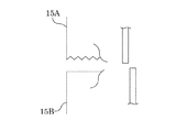
- Either the upper cutting blade 15A or the lower cutting blade 15B may have saw-tooth teeth so that the fiber reinforced resin 25 can be easily cut (FIG. 2).
- the upper cutting blade 15A and the lower cutting blade 15B are only required to be close to each other so as to be close to each other. As shown in FIG.
- the fiber reinforced resin 25 containing the reinforcing fiber having a long fiber length Position control of the upper cutting blade 15A and the lower cutting blade 15B is easy. If the fiber is rigid, the fiber reinforced resin 25 may become thicker than the discharge port due to the springback by becoming a long fiber. It is desirable to ensure at least twice the height of the discharge port.
- the moving means 17 can move the upper and lower cutting blades 15 forward in the fiber reinforced resin 25 fixed by the upper and lower fixed blades 13 and cut into the upper and lower cutting blades 15. It is only necessary that the reinforced resin 25 can be torn and cut.
- the operation timing and movement amount of the moving means 17 can be determined as appropriate.
- the cut portion of the fiber reinforced resin 25 has a moving table 28 that can receive the cut portion and discharge the received cut portion to a predetermined position.
- the fiber reinforced resin 25 preferably contains carbon fibers having a fiber length of 1 mm or more. This is because such fiber reinforced resin 25 is not easily cut. That is, the fiber reinforced resin cutting device 10 is suitably used for cutting the fiber reinforced resin 25 containing carbon fibers having a fiber length of 1 mm or more. The fiber reinforced resin cutting device 10 is preferably used for cutting a fiber reinforced resin 25 containing carbon fibers having a fiber length of 1 to 30 mm or less.
- the fiber reinforced resin 25 extruded from the extruder as shown in FIG. 1 (a) is fixed by the upper and lower fixed blades 13 and cut into the upper and lower cutting blades 15 as shown in FIG. 1 (b). It is.
- the upper and lower cutting blades 15 cut into the fiber reinforced resin 25 are moved forward. Thereby, the fiber reinforced resin 25 is cut so as to be torn off.
- the upper and lower cutting blades 15 are moved up and down, the cut portion of the fiber reinforced resin 25 that has been torn off is received by the moving table and discharged to a predetermined position (FIG. 1 (d)).
- the upper and lower fixed blades 13 are moved up and down to prepare for the next cycle (FIG. 1 (e)).
- a cutting test of a fiber reinforced resin 25 containing carbon fibers having different fiber lengths in polyamide 6 resin was performed.
- the fiber reinforced resin 25 is cut using a method (invention example) in which the fiber reinforced resin cutting device according to the present invention is used for cutting, and a stainless steel spatula having a thickness of 2 mm near the discharge port of the twin screw extruder. This was carried out by a manual cutting method using Comparative Example 1 (Comparative Examples 1 to 3).
- the reinforcing fiber resin 25 was produced by extruding a roving carbon fiber obtained by bundling polyamide 6 resin and a single fiber having a fiber diameter of 7 ⁇ m, using a twin screw extruder manufactured by Nippon Steel Works.
- the configuration of the screw element of the twin screw extruder and the screw rotation speed were adjusted, and the fiber length of the carbon fiber contained in the reinforcing fiber resin 25 was adjusted.
- the fiber length was measured by visual observation of the remaining carbon fiber after heating the fiber reinforced resin 25 at 550 ° C. for 6 hours in an electric furnace to burn off the resin component.
- the carbon fiber content of the fiber reinforced resin 25 was 30% by volume.
- the discharge temperature of the fiber reinforced resin 25 was 265 ° C.
- the discharge port size was 600 width ⁇ 10 mm thickness.
- FIG. 3 shows a cut piece obtained by cutting the fiber reinforced resin 25 with the fiber reinforced resin cutting device according to the present invention.
- the upper and lower sides of the cut piece are cut surfaces, and a torn state is observed, but the cut surface is relatively smooth.
- Table 1 shows the cutting results of the inventive example and the comparative example. It can be seen that cutting with a spatula is more difficult as the fiber length becomes longer, and becomes difficult when the fiber length exceeds several millimeters, especially 10 mm. When the fiber length exceeds 20 mm, it can be seen that it is difficult to cut the fiber reinforced resin 25 unless the fiber reinforced resin cutting device according to the present invention is used.
- the fiber-reinforced thermoplastic resin composition molded according to the present invention can be suitably used as a material for fiber-reinforced parts of various sizes made of long-fiber carbon fibers. For this reason, by using the present invention, it is possible to efficiently and economically produce fiber reinforced parts of various sizes made of long carbon fibers.
- Fiber reinforced resin cutting device 13 10 Fiber reinforced resin cutting device 13, 13A, 13B Upper and lower fixed blades 15, 15A, 15B Upper and lower cutting blades 17 Moving means 20 Extruder 25 Fiber reinforced resin 28 Moving table
Landscapes
- Engineering & Computer Science (AREA)
- Mechanical Engineering (AREA)
- Life Sciences & Earth Sciences (AREA)
- Forests & Forestry (AREA)
- Processing And Handling Of Plastics And Other Materials For Molding In General (AREA)
- Extrusion Moulding Of Plastics Or The Like (AREA)
- Nonmetal Cutting Devices (AREA)
- Reinforced Plastic Materials (AREA)
Abstract
本発明は、押出機から押し出された溶融熱可塑性樹脂が未だ固化していない状態の比較的長繊維の強化繊維を含む繊維強化熱可塑性樹脂組成物の切断を好適に行うことができる繊維強化樹脂切断装置を提供することを目的とする。 本発明に係る繊維強化樹脂切断装置は、押出機から前方に押し出される繊維強化樹脂を挟み込んで固定する上下動可能な上及び下固定刃と、この挟み込まれた繊維強化樹脂を前記上又は下固定刃の前面に沿ってそれぞれ移動して切り込む上下動可能な上及び下切断刃と、その切り込んだ状態の上及び下切断刃を前方に移動させる前後進可能な移動手段とを有し、前記繊維強化樹脂を引きちぎって所定長さに切断してなる。
Description
本発明は、押し出されて未だ溶融熱可塑性樹脂が固化していない繊維強化熱可塑性樹脂組成物の切断に使用される繊維強化樹脂切断装置に関する。
押出機により連続的に押し出された繊維強化熱可塑性樹脂組成物は、一般的に切断できる程度に固化された後、ペレタイザーなどにより切断されてペレット化され、その後射出成形などに供されている。
例えば、特許文献1に、押出機により押し出された炭素繊維に半芳香族ポリアミド樹脂を含浸させたストランドを冷却槽により冷却・固化させた後、ペレタイザーで切断する方法が記載されている。特許文献2に、強化用連続炭素繊維に酸基含有ポリオレフィン系樹脂を引き抜き法により含浸させて得られた繊維強化熱可塑性樹脂組成物を切断可能な温度まで冷却した後切断するとの記載がある。
特許文献1又は2に示されるように、繊維強化熱可塑性樹脂組成物がストランドのようなものである場合は、成形された繊維強化熱可塑性樹脂組成物を切断可能な程度に冷却・固化した後、工具鋼又はダイヤモンド製の切断刃を用いたペレタイザーなどにより容易に切断することができる。しかしながら、繊維強化熱可塑性樹脂組成物が炭素繊維を含有するものであってその容量が大きなものである場合は、切断刃の損傷が問題になる。
一方、押出機から押し出された繊維強化熱可塑性樹脂組成物は、作業効率やエネルギー効率の観点から、一旦冷却・固化することなく高温状態のままで次の加工工程に持ち込まれるのが望ましい場合がある。このような場合に、繊維強化熱可塑性樹脂組成物が高温状態にあって強化繊維が短小である場合は、強化繊維は切断されるというより押出機側又は切断される側のいずれかに分塊されるので、繊維強化熱可塑性樹脂組成物の切断は容易である。しかしながら、繊維強化熱可塑性樹脂組成物の強化繊維が長大である場合は、繊維強化熱可塑性樹脂組成物の切断は容易ではない。
本発明は、このような従来の問題点に鑑み、押出機から押し出され未だ溶融熱可塑性樹脂が固化していない状態の繊維強化熱可塑性樹脂組成物(繊維強化樹脂)、なかでも比較的長繊維の強化繊維を含むものの切断を好適に行うことができる繊維強化樹脂切断装置を提供することを目的とする。
本発明に係る繊維強化樹脂切断装置は、押出機から前方に押し出される繊維強化樹脂を挟み込んで固定する上下動可能な上及び下固定刃と、この挟み込まれた繊維強化樹脂を前記上又は下固定刃の前面に沿ってそれぞれ移動して切り込む上下動可能な上及び下切断刃と、その切り込んだ状態の上及び下切断刃を前方に移動させる前後進可能な移動手段とを有し、前記繊維強化樹脂を引きちぎって所定長さに切断してなる。
上記発明において、上及び下切断刃は、一方が鋸刃状の歯を有し、他方が歯を有しない平板状であるものがよい。この上及び下切断刃は、食い違うように切り込むことができるようにすることができる。
また、繊維強化樹脂に含有される強化繊維は炭素繊維とすることができる。繊維強化樹脂に含有される炭素繊維の繊維長が、1mm以上の場合に、本発明に係る繊維強化樹脂切断装置を好適に使用することができる。
また、本発明に係る繊維強化樹脂切断装置は、切断された繊維強化樹脂を受け取り、その受け取った繊維強化樹脂を所定位置に排出する移動台を有するものが好ましい。
本発明によれば、押出機から押し出された溶融熱可塑性樹脂が未だ固化していない状態の比較的長繊維の強化繊維を含む繊維強化樹脂(繊維強化熱可塑性樹脂組成物)の切断を容易に行うことができる。また、本発明によれば、長さが1mm以上の炭素繊維を有するものを含めて連続して成形される繊維強化樹脂組成物を次々に所望の大きさに切断することができるので、この所望の大きさに切断された繊維強化熱可塑性樹脂組成物を素材にして成形加工を施すことにより、炭素繊維強化部品などを効率的又経済的に生産することができる。
以下、本発明を実施するための形態について図面を基に説明する。図1は、本発明に係る繊維強化樹脂切断装置の構成と作動を示す模式図である。本繊維強化樹脂切断装置10は、図1(a)に示すように、押出機20から前方に押し出される繊維強化樹脂25を挟み込んで固定する上下動可能な上及び下固定刃13(13A、13B)と、この挟み込まれた繊維強化樹脂25を上又は下固定刃13の前面に沿ってそれぞれ移動して切り込む上下動可能な上及び下切断刃15(15A、15B)と、その切り込んだ状態の上及び下切断刃15を前方に移動させる前後進可能な移動手段17とを有している。この移動手段17を前方に移動することによって、繊維強化樹脂25を所定長さに引きちぎって切断することができる。
上及び下固定刃13(13A、13B)は、上固定刃13A、下固定刃13Bをそれぞれ上下動させ又所定位置に停止・固定させることができるようになっており、所定間隔で押出機20から前方に押し出される繊維強化樹脂25を所定の強さで挟み込んで固定することができるようになっている。上固定刃13A、下固定刃13Bの相対する部分は、繊維強化樹脂25を挟み込み・固定できる形状であればよく、平板状とすることができる。
上及び下切断刃15(15A、15B)は、上切断刃15A、下切断刃15Bをそれぞれ上下動させ又所定位置に停止・固定させることができるようになっており、上切断刃15Aは上固定刃13Aに沿って上下動し、下切断刃15Bは下固定刃13Bに沿って上下動するようになっている。上切断刃15A又は下切断刃15Bの何れかは、繊維強化樹脂25を容易に切り込むことができるように鋸刃状の歯を有するのがよい(図2)。上切断刃15Aと下切断刃15Bは、相互に対向して近接できるようになっていればよく、図2に示すように、食い違うように切り込むことができるようにすることができる。上切断刃15Aと下切断刃15Bが、食い違うように切り込むことができるようになっていると、繊維長の長い強化繊維を含有する繊維強化樹脂25の切断を確実に行うことができ、また、上切断刃15Aと下切断刃15Bの位置制御が容易である。繊維に剛性がある場合は長繊維になることでスプリングバックにより、繊維強化樹脂25は吐出口の高さより厚くなることが有るので、上切断刃15A、下切断刃15Bの上下動の可動域は吐出口の高さの2倍以上を確保しておくことが望ましい。
移動手段17は、上及び下固定刃13で固定され、上及び下切断刃15に切り込まれた状態の繊維強化樹脂25において、上及び下切断刃15を前方に移動させることができ、繊維強化樹脂25を引きちぎって切断することができるようになっていればよい。移動手段17の作動タイミング、移動量は、適宜決めることができるようになっている。
繊維強化樹脂25の切断された部分は、これを受け取り、その受け取った切断部分を所定位置に排出することができる移動台28を有するのがよい。
押出機20は、公知の押出機を使用することができる。繊維強化樹脂25は、繊維長が1mm以上の炭素繊維を含有するものがよい。このような繊維強化樹脂25は、切断が容易でないからである。すなわち、本繊維強化樹脂切断装置10は、繊維長が1mm以上の炭素繊維を含有する繊維強化樹脂25の切断に好適に使用される。本繊維強化樹脂切断装置10は、好ましくは、繊維長が1~30mm以下の炭素繊維を含有する繊維強化樹脂25の切断に使用される。
以下に、この繊維強化樹脂切断装置10により繊維強化樹脂25を切断する工程について説明する。図1(a)に示すように押出機から押し出された繊維強化樹脂25は、図1(b)に示すように、上及び下固定刃13で固定され、上及び下切断刃15に切り込まれる。次に、図1(c)に示すように、この繊維強化樹脂25に切り込んだ上及び下切断刃15を前方に移動させる。これによって、繊維強化樹脂25は引きちぎられるように切断される。次に、上及び下切断刃15を上下動させると、引きちぎられた繊維強化樹脂25の切断部分は、移動台により受け取られ、所定の位置に排出される(図1(d))。そして、上及び下固定刃13を上下動させ、次のサイクルに備える(図1(e))。
ポリアミド6樹脂に繊維長の異なる炭素繊維を含有する繊維強化樹脂25の切断試験を行った。繊維強化樹脂25の切断は、本発明に係る繊維強化樹脂切断装置を使用して切断する方法(発明例)と、二軸押出機の吐出口付近で作業員が板厚2mmのステンレス製のへらを使用した手作業で切断する方法(比較例1~3)により行った。強化繊維樹脂25は、株式会社日本製鋼所製二軸押出機を用い、ポリアミド6樹脂と繊維径7μmの単繊維を束ねたロービング状態の炭素繊維を押し出すことにより作製した。このとき、二軸押出機のスクリュエレメントの構成やスクリュ回転速度を調整し、強化繊維樹脂25に含有される炭素繊維の繊維長を調整した。繊維長は、繊維強化樹脂25を電気炉により550℃で6時間加熱し、樹脂分を焼き飛ばした後、残った炭素繊維を目視により計測した。繊維強化樹脂25の炭素繊維含有率は体積比で30%であった。繊維強化樹脂25の吐出温度は265℃であった。二軸押出機は、吐出口のサイズが幅600×厚さ10(mm)であった。
図3に、本発明に係る繊維強化樹脂切断装置により繊維強化樹脂25を切断した切断片を示す。この切断片の上下が切断面であり、引きちぎられた様子が観察されるが、切断面は比較的滑らかである。
表1に、発明例と比較例の切断結果を示す。へらによる切断は、繊維長が長いほど難しく、繊維長が数mm以上、特に10mmを越えると難しくなることが分かる。繊維長が20mmを越えると、本発明に係る繊維強化樹脂切断装置によらなければ繊維強化樹脂25の切断は困難であることが分かる。

本発明により成形される繊維強化熱可塑性樹脂組成物は、長繊維の炭素繊維からなる種々の大きさの繊維強化部品の素材として好適に利用することができる。このため、本発明を使用することにより、長繊維の炭素繊維からなる種々の大きさの繊維強化部品を効率的、経済的に生産することができる。
10 繊維強化樹脂切断装置
13、13A、13B 上及び下固定刃
15、15A、15B 上及び下切断刃
17 移動手段
20 押出機
25 繊維強化樹脂
28 移動台
13、13A、13B 上及び下固定刃
15、15A、15B 上及び下切断刃
17 移動手段
20 押出機
25 繊維強化樹脂
28 移動台
Claims (6)
- 押出機から前方に押し出される繊維強化樹脂を挟み込んで固定する上下動可能な上及び下固定刃と、この挟み込まれた繊維強化樹脂を前記上又は下固定刃の前面に沿ってそれぞれ移動して切り込む上下動可能な上及び下切断刃と、その切り込んだ状態の上及び下切断刃を前方に移動させる前後進可能な移動手段とを有し、前記繊維強化樹脂を引きちぎって所定長さに切断する繊維強化樹脂切断装置。
- 上及び下切断刃は、一方が鋸刃状の歯を有し、他方が歯を有しない平板状であることを特徴とする請求項1に記載の繊維強化樹脂切断装置。
- 上及び下切断刃は、食い違うように切り込むことができるようになっていることを特徴とする請求項2に記載の繊維強化樹脂切断装置。
- 繊維強化樹脂に含有される強化繊維は、炭素繊維であることを特徴とする請求項1に記載の繊維強化樹脂切断装置。
- 繊維強化樹脂に含有される炭素繊維の繊維長は、1mm以上であることを特徴とする請求項4に記載の繊維強化樹脂切断装置。
- 切断された繊維強化樹脂を受け取り、その受け取った繊維強化樹脂を所定位置に排出する移動台を有することを特徴とする請求項1に記載の繊維強化樹脂切断装置。
Applications Claiming Priority (2)
| Application Number | Priority Date | Filing Date | Title |
|---|---|---|---|
| JP2013-134363 | 2013-06-26 | ||
| JP2013134363A JP5762473B2 (ja) | 2013-06-26 | 2013-06-26 | 繊維強化樹脂切断装置 |
Publications (1)
| Publication Number | Publication Date |
|---|---|
| WO2014208576A1 true WO2014208576A1 (ja) | 2014-12-31 |
Family
ID=52141908
Family Applications (1)
| Application Number | Title | Priority Date | Filing Date |
|---|---|---|---|
| PCT/JP2014/066787 Ceased WO2014208576A1 (ja) | 2013-06-26 | 2014-06-25 | 繊維強化樹脂切断装置 |
Country Status (2)
| Country | Link |
|---|---|
| JP (1) | JP5762473B2 (ja) |
| WO (1) | WO2014208576A1 (ja) |
Citations (5)
| Publication number | Priority date | Publication date | Assignee | Title |
|---|---|---|---|---|
| JPS53154175U (ja) * | 1977-05-11 | 1978-12-04 | ||
| JPH04152016A (ja) * | 1990-10-17 | 1992-05-26 | O K B Kk | 金属チューブ分断法 |
| JP2010116428A (ja) * | 2008-11-11 | 2010-05-27 | Tosoh Corp | 再生繊維状充填材強化ポリフェニレンスルフィド粒状物の製造方法 |
| JP2011063029A (ja) * | 2010-11-12 | 2011-03-31 | Daicel Chemical Industries Ltd | 被熱処理炭素長繊維強化樹脂ペレットの製造方法 |
| JP2011245755A (ja) * | 2010-05-27 | 2011-12-08 | Teijin Ltd | 炭素繊維の樹脂含浸ストランドおよびペレットの製造方法 |
Family Cites Families (1)
| Publication number | Priority date | Publication date | Assignee | Title |
|---|---|---|---|---|
| JPS62113514A (ja) * | 1985-11-13 | 1987-05-25 | Plast Kogaku Kenkyusho:Kk | 複合材製造装置 |
-
2013
- 2013-06-26 JP JP2013134363A patent/JP5762473B2/ja active Active
-
2014
- 2014-06-25 WO PCT/JP2014/066787 patent/WO2014208576A1/ja not_active Ceased
Patent Citations (5)
| Publication number | Priority date | Publication date | Assignee | Title |
|---|---|---|---|---|
| JPS53154175U (ja) * | 1977-05-11 | 1978-12-04 | ||
| JPH04152016A (ja) * | 1990-10-17 | 1992-05-26 | O K B Kk | 金属チューブ分断法 |
| JP2010116428A (ja) * | 2008-11-11 | 2010-05-27 | Tosoh Corp | 再生繊維状充填材強化ポリフェニレンスルフィド粒状物の製造方法 |
| JP2011245755A (ja) * | 2010-05-27 | 2011-12-08 | Teijin Ltd | 炭素繊維の樹脂含浸ストランドおよびペレットの製造方法 |
| JP2011063029A (ja) * | 2010-11-12 | 2011-03-31 | Daicel Chemical Industries Ltd | 被熱処理炭素長繊維強化樹脂ペレットの製造方法 |
Also Published As
| Publication number | Publication date |
|---|---|
| JP5762473B2 (ja) | 2015-08-12 |
| JP2015009288A (ja) | 2015-01-19 |
Similar Documents
| Publication | Publication Date | Title |
|---|---|---|
| TWI688592B (zh) | 纖維強化樹脂成形材料及其製造方法 | |
| JP6490757B2 (ja) | 幅狭フレーク状の複合繊維材料の圧縮成形法 | |
| EP4035860A3 (en) | Method and apparatus for producing fiber-reinforced resin molding material | |
| EP3515677B1 (de) | Verfahren und vorrichtung für das recycling von thermoplastischem faserverbundmaterial | |
| CN105377461B (zh) | 用于弯曲金属产品的机器和相应的弯曲方法 | |
| CN212147100U (zh) | 一种牵引装置及具有该牵引装置的挤出造粒设备 | |
| CN104985778A (zh) | 一种全自动端子进给系统 | |
| JPWO2018055932A1 (ja) | 切込プリプレグ及び切込プリプレグの製造方法 | |
| JPWO2020218233A1 (ja) | 繊維強化樹脂製締結具の製造方法および繊維強化樹脂製締結具 | |
| CN207326074U (zh) | 一种型材锯切装置 | |
| JP6641315B2 (ja) | 裁断分離装置及び繊維強化樹脂成形体の製造装置 | |
| JP2016078308A (ja) | 繊維強化熱可塑性樹脂成形品の製造方法 | |
| JP5762473B2 (ja) | 繊維強化樹脂切断装置 | |
| JP6933951B2 (ja) | 繊維強化熱可塑性樹脂の混練方法および可塑化装置 | |
| WO2016093320A1 (ja) | 裁断装置及びその運転方法 | |
| FR3056136A1 (fr) | Systeme de decoupe d'un tissu de fibres de renfort pour la fabrication de feuilles en matiere plastique renforcee | |
| CN203752535U (zh) | 一种用于选择性激光烧结的纤维植入装置 | |
| CN209608079U (zh) | 一种自动剪编织机构 | |
| CN202399307U (zh) | 角度切割机 | |
| CN201833074U (zh) | 数控钢管切割料架 | |
| FR2916003B1 (fr) | Systeme destine a la fabrication de fils coupes en matiere thermoplastique. | |
| CN104400820A (zh) | 泡沫塑料用切割设备 | |
| CN205969186U (zh) | 一种摆动玻纤切断装置 | |
| CN204662136U (zh) | 一种纤维布料连续自动变模裁切装置及纤维布注胶成型制品生产设备 | |
| CN203270343U (zh) | 一种编织袋切刀装置 |
Legal Events
| Date | Code | Title | Description |
|---|---|---|---|
| 121 | Ep: the epo has been informed by wipo that ep was designated in this application |
Ref document number: 14817700 Country of ref document: EP Kind code of ref document: A1 |
|
| NENP | Non-entry into the national phase |
Ref country code: DE |
|
| 122 | Ep: pct application non-entry in european phase |
Ref document number: 14817700 Country of ref document: EP Kind code of ref document: A1 |