WO2014208384A1 - 表示装置及びテレビ受像機 - Google Patents
表示装置及びテレビ受像機 Download PDFInfo
- Publication number
- WO2014208384A1 WO2014208384A1 PCT/JP2014/065898 JP2014065898W WO2014208384A1 WO 2014208384 A1 WO2014208384 A1 WO 2014208384A1 JP 2014065898 W JP2014065898 W JP 2014065898W WO 2014208384 A1 WO2014208384 A1 WO 2014208384A1
- Authority
- WO
- WIPO (PCT)
- Prior art keywords
- optical sheet
- display device
- display panel
- light guide
- guide plate
- Prior art date
- Legal status (The legal status is an assumption and is not a legal conclusion. Google has not performed a legal analysis and makes no representation as to the accuracy of the status listed.)
- Ceased
Links
Images



Classifications
-
- G—PHYSICS
- G02—OPTICS
- G02B—OPTICAL ELEMENTS, SYSTEMS OR APPARATUS
- G02B6/00—Light guides; Structural details of arrangements comprising light guides and other optical elements, e.g. couplings
- G02B6/0001—Light guides; Structural details of arrangements comprising light guides and other optical elements, e.g. couplings specially adapted for lighting devices or systems
- G02B6/0011—Light guides; Structural details of arrangements comprising light guides and other optical elements, e.g. couplings specially adapted for lighting devices or systems the light guides being planar or of plate-like form
- G02B6/0081—Mechanical or electrical aspects of the light guide and light source in the lighting device peculiar to the adaptation to planar light guides, e.g. concerning packaging
- G02B6/0086—Positioning aspects
- G02B6/0088—Positioning aspects of the light guide or other optical sheets in the package
-
- G—PHYSICS
- G02—OPTICS
- G02B—OPTICAL ELEMENTS, SYSTEMS OR APPARATUS
- G02B6/00—Light guides; Structural details of arrangements comprising light guides and other optical elements, e.g. couplings
- G02B6/0001—Light guides; Structural details of arrangements comprising light guides and other optical elements, e.g. couplings specially adapted for lighting devices or systems
- G02B6/0011—Light guides; Structural details of arrangements comprising light guides and other optical elements, e.g. couplings specially adapted for lighting devices or systems the light guides being planar or of plate-like form
- G02B6/0066—Light guides; Structural details of arrangements comprising light guides and other optical elements, e.g. couplings specially adapted for lighting devices or systems the light guides being planar or of plate-like form characterised by the light source being coupled to the light guide
- G02B6/0068—Arrangements of plural sources, e.g. multi-colour light sources
-
- G—PHYSICS
- G02—OPTICS
- G02B—OPTICAL ELEMENTS, SYSTEMS OR APPARATUS
- G02B6/00—Light guides; Structural details of arrangements comprising light guides and other optical elements, e.g. couplings
- G02B6/0001—Light guides; Structural details of arrangements comprising light guides and other optical elements, e.g. couplings specially adapted for lighting devices or systems
- G02B6/0011—Light guides; Structural details of arrangements comprising light guides and other optical elements, e.g. couplings specially adapted for lighting devices or systems the light guides being planar or of plate-like form
- G02B6/0066—Light guides; Structural details of arrangements comprising light guides and other optical elements, e.g. couplings specially adapted for lighting devices or systems the light guides being planar or of plate-like form characterised by the light source being coupled to the light guide
- G02B6/0073—Light emitting diode [LED]
-
- G—PHYSICS
- G02—OPTICS
- G02F—OPTICAL DEVICES OR ARRANGEMENTS FOR THE CONTROL OF LIGHT BY MODIFICATION OF THE OPTICAL PROPERTIES OF THE MEDIA OF THE ELEMENTS INVOLVED THEREIN; NON-LINEAR OPTICS; FREQUENCY-CHANGING OF LIGHT; OPTICAL LOGIC ELEMENTS; OPTICAL ANALOGUE/DIGITAL CONVERTERS
- G02F1/00—Devices or arrangements for the control of the intensity, colour, phase, polarisation or direction of light arriving from an independent light source, e.g. switching, gating or modulating; Non-linear optics
- G02F1/01—Devices or arrangements for the control of the intensity, colour, phase, polarisation or direction of light arriving from an independent light source, e.g. switching, gating or modulating; Non-linear optics for the control of the intensity, phase, polarisation or colour
- G02F1/13—Devices or arrangements for the control of the intensity, colour, phase, polarisation or direction of light arriving from an independent light source, e.g. switching, gating or modulating; Non-linear optics for the control of the intensity, phase, polarisation or colour based on liquid crystals, e.g. single liquid crystal display cells
- G02F1/133—Constructional arrangements; Operation of liquid crystal cells; Circuit arrangements
- G02F1/1333—Constructional arrangements; Manufacturing methods
- G02F1/133308—Support structures for LCD panels, e.g. frames or bezels
-
- G—PHYSICS
- G02—OPTICS
- G02F—OPTICAL DEVICES OR ARRANGEMENTS FOR THE CONTROL OF LIGHT BY MODIFICATION OF THE OPTICAL PROPERTIES OF THE MEDIA OF THE ELEMENTS INVOLVED THEREIN; NON-LINEAR OPTICS; FREQUENCY-CHANGING OF LIGHT; OPTICAL LOGIC ELEMENTS; OPTICAL ANALOGUE/DIGITAL CONVERTERS
- G02F1/00—Devices or arrangements for the control of the intensity, colour, phase, polarisation or direction of light arriving from an independent light source, e.g. switching, gating or modulating; Non-linear optics
- G02F1/01—Devices or arrangements for the control of the intensity, colour, phase, polarisation or direction of light arriving from an independent light source, e.g. switching, gating or modulating; Non-linear optics for the control of the intensity, phase, polarisation or colour
- G02F1/13—Devices or arrangements for the control of the intensity, colour, phase, polarisation or direction of light arriving from an independent light source, e.g. switching, gating or modulating; Non-linear optics for the control of the intensity, phase, polarisation or colour based on liquid crystals, e.g. single liquid crystal display cells
- G02F1/133—Constructional arrangements; Operation of liquid crystal cells; Circuit arrangements
- G02F1/1333—Constructional arrangements; Manufacturing methods
- G02F1/1335—Structural association of cells with optical devices, e.g. polarisers or reflectors
- G02F1/1336—Illuminating devices
- G02F1/133602—Direct backlight
- G02F1/133608—Direct backlight including particular frames or supporting means
-
- G—PHYSICS
- G02—OPTICS
- G02F—OPTICAL DEVICES OR ARRANGEMENTS FOR THE CONTROL OF LIGHT BY MODIFICATION OF THE OPTICAL PROPERTIES OF THE MEDIA OF THE ELEMENTS INVOLVED THEREIN; NON-LINEAR OPTICS; FREQUENCY-CHANGING OF LIGHT; OPTICAL LOGIC ELEMENTS; OPTICAL ANALOGUE/DIGITAL CONVERTERS
- G02F1/00—Devices or arrangements for the control of the intensity, colour, phase, polarisation or direction of light arriving from an independent light source, e.g. switching, gating or modulating; Non-linear optics
- G02F1/01—Devices or arrangements for the control of the intensity, colour, phase, polarisation or direction of light arriving from an independent light source, e.g. switching, gating or modulating; Non-linear optics for the control of the intensity, phase, polarisation or colour
- G02F1/13—Devices or arrangements for the control of the intensity, colour, phase, polarisation or direction of light arriving from an independent light source, e.g. switching, gating or modulating; Non-linear optics for the control of the intensity, phase, polarisation or colour based on liquid crystals, e.g. single liquid crystal display cells
- G02F1/133—Constructional arrangements; Operation of liquid crystal cells; Circuit arrangements
- G02F1/1333—Constructional arrangements; Manufacturing methods
- G02F1/1335—Structural association of cells with optical devices, e.g. polarisers or reflectors
- G02F1/1336—Illuminating devices
- G02F1/133615—Edge-illuminating devices, i.e. illuminating from the side
-
- G—PHYSICS
- G09—EDUCATION; CRYPTOGRAPHY; DISPLAY; ADVERTISING; SEALS
- G09G—ARRANGEMENTS OR CIRCUITS FOR CONTROL OF INDICATING DEVICES USING STATIC MEANS TO PRESENT VARIABLE INFORMATION
- G09G3/00—Control arrangements or circuits, of interest only in connection with visual indicators other than cathode-ray tubes
- G09G3/20—Control arrangements or circuits, of interest only in connection with visual indicators other than cathode-ray tubes for presentation of an assembly of a number of characters, e.g. a page, by composing the assembly by combination of individual elements arranged in a matrix no fixed position being assigned to or needed to be assigned to the individual characters or partial characters
- G09G3/34—Control arrangements or circuits, of interest only in connection with visual indicators other than cathode-ray tubes for presentation of an assembly of a number of characters, e.g. a page, by composing the assembly by combination of individual elements arranged in a matrix no fixed position being assigned to or needed to be assigned to the individual characters or partial characters by control of light from an independent source
- G09G3/36—Control arrangements or circuits, of interest only in connection with visual indicators other than cathode-ray tubes for presentation of an assembly of a number of characters, e.g. a page, by composing the assembly by combination of individual elements arranged in a matrix no fixed position being assigned to or needed to be assigned to the individual characters or partial characters by control of light from an independent source using liquid crystals
-
- G—PHYSICS
- G02—OPTICS
- G02F—OPTICAL DEVICES OR ARRANGEMENTS FOR THE CONTROL OF LIGHT BY MODIFICATION OF THE OPTICAL PROPERTIES OF THE MEDIA OF THE ELEMENTS INVOLVED THEREIN; NON-LINEAR OPTICS; FREQUENCY-CHANGING OF LIGHT; OPTICAL LOGIC ELEMENTS; OPTICAL ANALOGUE/DIGITAL CONVERTERS
- G02F2201/00—Constructional arrangements not provided for in groups G02F1/00 - G02F7/00
- G02F2201/50—Protective arrangements
Definitions
- the present invention relates to a display device and a television receiver including the display device.
- a conventional liquid crystal display device has a backlight chassis that supports a plurality of fluorescent tubes arranged in a row, an optical sheet that is held in the backlight chassis and diffuses light emitted from the fluorescent tubes, and an image is generated by light transmitted through the optical sheet.
- a liquid crystal display panel or the like see Patent Documents 1 and 2).
- LEDs have been widely used as light sources and the like, and are employed in backlights of liquid crystal display devices.
- a liquid crystal display device there is an edge light type device including a light guide plate arranged on the back side of a liquid crystal display panel, an LED arranged opposite to an end surface of the light guide plate, and the like. The light emitted from the LED enters the light guide plate from the end face of the light guide plate, passes through the light guide plate, and enters the liquid crystal display panel from the back side of the liquid crystal display panel.
- the optical sheet can be fixed to the backlight chassis, when the LED is used as the backlight, the liquid crystal display There is a demand for thinning and narrowing of the apparatus, there is no gap for arranging the optical sheet, and it is difficult to hold or fix the optical sheet. Further, if the optical sheet cannot be securely held or fixed, the optical sheet may move due to external force such as vibration or impact applied to the liquid crystal display device, and may contact the liquid crystal panel and damage the liquid crystal panel.
- the present invention has been made in view of such circumstances, and an object thereof is to provide a display device capable of reliably holding an optical sheet and a television receiver including the display device.
- the display device includes a light guide plate, a plurality of light source elements arranged to face the end face of the light guide plate, an optical sheet arranged on one surface side of the light guide plate, and arranged to face the optical sheet.
- a display device comprising a display panel, a first holding unit that shields light from the plurality of light source elements and holds the optical sheet from the light guide plate side, and the optical sheet from the opposite side to the first holding unit.
- a second holding portion for holding, and a gap is provided between the optical sheet and the display panel by the second holding portion.
- the first holding portion has a locking portion for locking the optical sheet
- the optical sheet has a locked portion for locking the locking portion.
- the display device is characterized in that the second holding portion is in contact with the vicinity of the locked portion of the optical sheet.
- the display device is characterized in that the locked portion is a hole provided in the optical sheet, and the locking portion is a protrusion fitted into the hole.
- a television receiver includes the display device according to the present invention and a receiving unit that receives a television signal, and the display device displays an image based on the television signal received by the receiving unit. It is characterized by that.
- the optical sheet can be securely held.
- FIG. 2 is an external perspective view illustrating an example of a configuration of a television receiver according to the first embodiment.
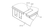
- FIG. 3 is a cross-sectional view illustrating a main part of the display device according to the first embodiment. 3 is a perspective view of a main part showing an example of a configuration of an optical sheet according to Embodiment 1.
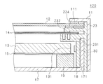
- FIG. 10 is a cross-sectional view illustrating a main part of a display device according to a second embodiment.
- FIG. 10 is a cross-sectional view illustrating a main part of a display device according to a third embodiment.
- FIG. 1 is an external perspective view showing an example of the configuration of the television receiver 200 according to the first embodiment.
- the television receiver 200 includes a display device 100, a receiving unit 150 that receives a television signal, a stand 201, and the like.
- Display device 100 displays an image based on the television signal received by receiving unit 150.
- the display device 100 is a rectangular liquid crystal panel, and includes a display panel 12 whose one surface is a display surface, a bezel 11 that covers a peripheral portion of the display panel 12, and the like.
- details of the display device 100 will be described.
- FIG. 2 is a cross-sectional view showing a main part of the display device 100 of the first embodiment.
- the display device 100 includes a display panel 12 having a display surface on one surface (front surface), a light guide plate 13 disposed on the other surface side (back surface side) of the display panel, and an end surface 131 of the light guide plate 13.
- the LED 30 as a plurality of light source elements arranged in opposition, the substrate 18 on which the LEDs 30 are mounted on one surface, the optical sheet 14 disposed on the display panel 12 side of the light guide plate 13, and the substrate 18 are fixed and the back covers the light guide plate 13
- a bezel 11 that covers the light frame 17, the peripheral edge of the display panel 12, and the side surface of the backlight frame 17 is provided.
- the light source unit employs a so-called edge light system, and is constituted by components or members excluding the display panel 12 and the bezel 11 from the display device 100.
- the light guide plate 13 LED 30, optical sheet 14, backlight frame 17, and the like.
- the display panel 12 has a glass substrate on one surface (front surface) and the other surface (back surface), and a liquid crystal substance is sealed between the pair of glass substrates.
- a voltage to a driver that drives each pixel of the display panel 12 the light transmittance determined by the electro-optical characteristics of the liquid crystal substance can be changed, and the amount of light transmitted through the display panel 12 is controlled for each pixel.
- the image can be displayed in gradation.
- the light guide plate 13 has a rectangular shape, and the vertical and horizontal dimensions are substantially the same as the vertical and horizontal dimensions of the display panel 12.
- the material of the light guide plate 13 is, for example, an acrylic resin or a polycarbonate resin, but is not limited thereto.
- the light guide plate 13 is disposed on the other surface side of the display panel 12 (the side opposite to the display surface).
- the optical sheet 14 has a rectangular shape that is slightly smaller than the dimensions of the display panel 12.
- the optical sheet 14 is obtained by laminating one or a plurality of optical sheets having a light diffusion function and optical sheets having a light condensing function.
- the display panel 12 is disposed to face the optical sheet 14.
- the optical sheet 14 is disposed on the display panel 12 side of the light guide plate 13.
- the reflection sheet 15 has a rectangular shape slightly larger than the dimension of the light guide plate 13.
- the reflection sheet 15 reflects light emitted from the back surface (back surface) of the light guide plate 13 and makes it enter the light guide plate 13 again.
- the substrate 18 has an elongated shape, and a plurality of LEDs 30 are arranged at appropriate intervals. That is, the plurality of LEDs 30 are arranged linearly along the longitudinal direction of the substrate 18. Accordingly, the LED 30 is disposed to face the end surface 131 of the light guide plate 13.
- the length of the substrate 18 is substantially equal to the vertical dimension or the horizontal dimension of the light guide plate 13, for example.
- the total length of the plurality of substrates 18 is substantially equal to the vertical dimension or the horizontal dimension of the light guide plate 13.
- the light emitted from the LED 30 enters from the end face 131 of the light guide plate 13.
- the incident light exits from the exit surface of the light guide plate 13, is diffused and collected by the optical sheet 14, and enters the display panel 12 from the back surface of the display panel 12. Thereby, the display surface of the display panel 12 becomes uniform brightness.
- the backlight frame 17 has vertical and horizontal dimensions that are the same as the vertical and horizontal dimensions of the display panel 12, and has a standing plate 171 that is erected with its peripheral edge bent in a substantially L shape.
- the height dimension of the upright plate 171 is equivalent to the width dimension of the substrate 18.
- the inner surface of the upright plate 171 is in contact with the other surface of the substrate 18, and the upright plate 171 supports the substrate 18.
- the backlight frame 17 has a fixing portion 19 that supports and fixes the light guide plate 13.
- the back of the backlight frame 17 is covered with a housing such as a cabinet (not shown).
- a chassis 21 is provided as a first holding part having a substantially L-shaped cross section. That is, the chassis 21 includes a contact plate 211 that contacts the standing plate 171 and a holding plate 212 that is bent and extended by approximately 90 degrees from the contact plate 211.
- the holding plate 212 is arranged in parallel to the longitudinal direction of the light guide plate 13.
- the holding plate 212 has a function of shielding light emitted from the LEDs 30 disposed to face the end surface 131 of the light guide plate 13 from being emitted to the display panel 12.
- the holding plate 212 has a function of holding the optical sheet 14 from the light guide plate 13 side. That is, the optical sheet 14 is disposed on the upper surface (the display panel 12 side) of the holding plate 212.
- the optical sheet 14 By disposing the optical sheet 14 on the upper surface of the holding plate 212, the optical sheet 14 can be disposed between the light guide plate 13 and the display panel 12, and the light source unit can be narrowed. . In addition, since the optical sheet 14 is on the upper surface of the holding plate 212, the light is diffused by the optical sheet 14 even if the light from the LED 30 is shielded by the holding plate 212 and there is a shadow portion. It is possible to eliminate unevenness.
- FIG. 3 is a main part perspective view showing an example of the configuration of the optical sheet 14 of the first embodiment.
- the holding plate 212 has a protrusion 213 as a locking portion for locking the optical sheet 14 on the surface on which the optical sheet 14 is arranged.
- the optical sheet 14 has a hole 141 as a locked portion to which the protruding portion 213 is locked. That is, the locked portion is a hole 141 provided in the optical sheet 14, and the locking portion is a protrusion 213 that fits into the hole 141.
- the protruding portion 213 of the holding plate 212 is locked in the hole 141 of the optical sheet 14, the movement of the optical sheet 14 can be restricted, and the optical sheet 14 can be reliably held.
- the shape or dimension of the projection part 213 and the hole 141 can be determined suitably.
- the chassis 22 has a function as a second holding unit, and holds the optical sheet 14 from the side opposite to the holding plate 212 by separating the display panel 12 and the optical sheet 14.
- the chassis 22 includes a contact plate 221 that contacts the inner surface of the bezel 11 and a holding plate 222 that is bent and extended from the contact plate 221 by approximately 90 degrees.
- the holding plate 222 is disposed in parallel to the longitudinal direction of the light guide plate 13.
- a holding plate 212 that holds the optical sheet 14 from the light guide plate 13 side and a holding plate 222 that holds the optical sheet 14 from the side opposite to the holding plate 212 are provided. Thereby, the optical sheet 14 can be reliably held.
- the holding plate 222 is formed with a contact portion 223 that contacts the vicinity of the hole 141 of the optical sheet 14. Since the optical sheet 14 is contacted from the display panel 12 side by the contact portion 221, movement and floating of the optical sheet 14 can be restricted, and the optical sheet 14 can be held more reliably.
- the holding plate 222 Since the holding plate 222 is disposed between the hole 141 of the optical sheet 14 and the protrusion 213 of the holding plate 212 and the peripheral portion of the display panel 12, the holding plate 222 allows the display panel 12 to be viewed from the display surface side. Even in this case, it is possible to prevent the end portion of the optical sheet 14 and the portion that holds the optical sheet 14 (for example, the protruding portion 213 and the hole 141) from being directly visible.
- the holding plate 222 is disposed between the display panel 12 and the optical sheet 14, a gap (required separation distance) can be provided between the display panel 12 and the optical sheet 14. And the display panel 12 can be prevented from contacting each other. Thereby, breakage or damage of the display panel 12 or breakage of the optical sheet 14 can be prevented, and deterioration of the display quality of the display panel 12 can be prevented.
- the gap adjusting member 224 is provided between the holding plate 222 and the display panel 12, but the gap adjusting member 224 is not essential.
- the bezel 11 has a substantially L-shaped cross section and is arranged so as to cover the peripheral portion of the display panel 12 and the standing plate 171 of the backlight frame 17 through the chassis 21 and 22.
- a holding portion 111 that holds the display panel 12 is provided at the end of the bezel 11.
- Each of the bezel 11, the chassis 21, 22 and the standing plate 171 is formed with a screw hole (not shown), and the bezel 11, the chassis 21, 22 and the backlight frame 17 are fixed by fastening the screws. Can do.
- FIG. 4 is a cross-sectional view illustrating a main part of the display device 110 according to the second embodiment.
- the protruding portion 213 is formed on the holding plate 212 as the first holding portion.
- the protruding portion 225 is formed on the holding plate 222 as the second holding portion.
- symbol is attached
- the holding plate 222 has a protrusion 225 serving as a locking portion for locking the optical sheet 14 on the surface on which the optical sheet 14 is disposed.
- the optical sheet 14 has a hole 141 as a locked portion to which the protruding portion 225 is locked.
- the movement of the optical sheet 14 can be restricted, and the optical sheet 14 can be reliably held.
- the shape or dimension of the protrusion part 225 and the hole 141 can be determined suitably.
- a gap (required separation distance) may be provided between the display panel 12 and the optical sheet 14. It is possible to prevent the optical sheet 14 and the display panel 12 from contacting each other. Thereby, breakage or damage of the display panel 12 or breakage of the optical sheet 14 can be prevented, and deterioration of the display quality of the display panel 12 can be prevented.
- FIG. 5 is a cross-sectional view showing a main part of the display device 120 according to the third embodiment.
- the chassis 21 as the first holding unit and the chassis 22 as the second holding unit are separate members, but in the third embodiment, the chassis 21 and 22 are integrated. 23.
- symbol is attached
- the integrated chassis 23 includes a holding plate 231 that holds the optical sheet 14 from the light guide plate 13 side, and a holding plate 232 that holds the optical sheet 14 from the side opposite to the holding plate 231. Thereby, the optical sheet 14 can be reliably held.
- the optical sheet 14 By disposing the optical sheet 14 on the upper surface of the holding plate 231, the optical sheet 14 can be disposed between the light guide plate 13 and the display panel 12, and the light source unit can be narrowed. . Further, since the optical sheet 14 is on the upper surface of the holding plate 231, even if the light from the LED 30 is shielded by the holding plate 231 and there is a shadow portion, the light is diffused by the optical sheet 14, and therefore the holding plate 231. It is possible to eliminate unevenness.
- the holding plate 232 is disposed between the display panel 12 and the optical sheet 14, a gap (required separation distance) can be provided between the display panel 12 and the optical sheet 14. And the display panel 12 can be prevented from contacting each other. Thereby, breakage or damage of the display panel 12 or breakage of the optical sheet 14 can be prevented, and deterioration of the display quality of the display panel 12 can be prevented.
Landscapes
- Physics & Mathematics (AREA)
- General Physics & Mathematics (AREA)
- Optics & Photonics (AREA)
- Nonlinear Science (AREA)
- Chemical & Material Sciences (AREA)
- Crystallography & Structural Chemistry (AREA)
- Mathematical Physics (AREA)
- Engineering & Computer Science (AREA)
- Computer Hardware Design (AREA)
- Theoretical Computer Science (AREA)
- Microelectronics & Electronic Packaging (AREA)
- Liquid Crystal (AREA)
Abstract
光学シートを確実に保持することができる表示装置及びテレビ受像機を提供する。 表示装置は、一面に表示面を有する表示パネルの他面側に配置される導光板と、導光板の端面に対向配置された複数の光源素子と、導光板の表示パネル側に配置された光学シートと、光学シートに対向配置された表示パネルとを備え、さらに、複数の光源素子からの光が表示パネルへ出射されるのを遮蔽し、光学シートを導光板側から保持する第1保持部と、表示パネルと光学シートとを離隔させて光学シートを第1保持部と反対側から保持する第2保持部とを備える。そして、第2保持部により光学シートと表示パネルとの間に隙間を設けてある。
Description
本発明は、表示装置及び該表示装置を備えるテレビ受像機に関する。
従来の液晶表示装置は、列置された複数の蛍光管を支持するバックライトシャーシ、バックライトシャーシに保持され、蛍光管から照射された光を拡散する光学シート、光学シートを透過した光により映像を表示する液晶表示パネルなどを備える(特許文献1、2参照)。
一方、近年ではLEDの高輝度化に伴って、LEDが光源等として広く使用されるようになり、液晶表示装置のバックライトに採用されている。このような液晶表示装置としては、液晶表示パネルの裏面側に配置された導光板、導光板の端面に対向配置したLEDなどを備えたエッジライト方式のものがある。LEDから発せられた光は、導光板の端面から導光板内部に入射し、導光板を通って液晶表示パネルの裏面側から液晶表示パネルの内部に入射される。
しかし、特許文献1、2のような蛍光管を用いた液晶表示装置にあっては、光学シートをバックライトシャーシに固定することができたものの、バックライトとしてLEDを用いる場合には、液晶表示装置の薄型化、狭額縁化の要求があり、光学シートを配置するための隙間がなく、光学シートを保持又は固定することが困難であった。また、光学シートを確実に保持又は固定することができないと、液晶表示装置に加わる振動又は衝撃などの外力により、光学シートが移動し、液晶パネルと接触して液晶パネルを破損させるおそれもある。
本発明は斯かる事情に鑑みてなされたものであり、光学シートを確実に保持することができる表示装置及び該表示装置を備えるテレビ受像機を提供することを目的とする。
本発明に係る表示装置は、導光板と、前記導光板の端面に対向配置された複数の光源素子と、前記導光板の一面側に配置された光学シートと、該光学シートに対向配置された表示パネルとを備える表示装置において、前記複数の光源素子からの光を遮蔽し、前記光学シートを導光板側から保持する第1保持部と、前記光学シートを前記第1保持部と反対側から保持する第2保持部とを備え、該第2保持部により前記光学シートと表示パネルとの間に隙間を設けたことを特徴とする。
本発明に係る表示装置は、前記第1保持部は、前記光学シートを係止する係止部を有し、前記光学シートは、前記係止部が係止する被係止部を有することを特徴とする。
本発明に係る表示装置は、前記第2保持部は、前記光学シートの被係止部の近傍に当接するようにしてあることを特徴とする。
本発明に係る表示装置は、前記被係止部は、前記光学シートに設けられた孔であり、前記係止部は、前記孔に嵌合する突起部であることを特徴とする。
本発明に係るテレビ受像機は、本発明に係る表示装置と、テレビジョン信号を受信する受信部とを備え、前記表示装置は、前記受信部で受信したテレビジョン信号に基づく映像を表示するようにしてあることを特徴とする。
本発明によれば、光学シートを確実に保持することができる。
(実施の形態1)
以下、本発明をその実施の形態を示す図面に基づいて説明する。図1は実施の形態1のテレビ受像機200の構成の一例を示す外観斜視図である。テレビ受像機200は、表示装置100、テレビジョン信号を受信する受信部150、スタンド201などを備える。表示装置100は、受信部150で受信したテレビジョン信号に基づく映像を表示する。また、表示装置100は、矩形状の液晶パネルであって、一面が表示面となる表示パネル12、表示パネル12の周縁部を覆うベゼル11などを備える。以下、表示装置100の詳細について説明する。
以下、本発明をその実施の形態を示す図面に基づいて説明する。図1は実施の形態1のテレビ受像機200の構成の一例を示す外観斜視図である。テレビ受像機200は、表示装置100、テレビジョン信号を受信する受信部150、スタンド201などを備える。表示装置100は、受信部150で受信したテレビジョン信号に基づく映像を表示する。また、表示装置100は、矩形状の液晶パネルであって、一面が表示面となる表示パネル12、表示パネル12の周縁部を覆うベゼル11などを備える。以下、表示装置100の詳細について説明する。
図2は実施の形態1の表示装置100の要部を示す断面図である。図2に示すように、表示装置100は、一面(表面)に表示面を有する表示パネル12、表示パネルの他面側(裏面側)に配置された導光板13、導光板13の端面131に対向配置された複数の光源素子としてのLED30、LED30を一面に実装した基板18、導光板13の表示パネル12側に配置された光学シート14、基板18を固定するとともに、導光板13を覆うバックライトフレーム17、表示パネル12の周縁部及びバックライトフレーム17の側面を覆うベゼル11などを備える。
なお、本実施の形態において、光源ユニットは、いわゆるエッジライト方式を採用したものであり、表示装置100から、表示パネル12、ベゼル11などを除いた部品又は部材で構成され、例えば、導光板13、LED30、光学シート14、バックライトフレーム17などを備える。
表示パネル12は、一面(表面)及び他面(裏面)にガラス基板を有し、一対のガラス基板の間に液晶物質を封入してある。表示パネル12の各画素を駆動するドライバに電圧を印加して、液晶物質の電気光学特性により決定される光透過率を変えることができ、表示パネル12を透過する光の量を画素毎に制御して画像を階調表示することができる。
導光板13は、矩形状をなし、縦横寸法は、表示パネル12の縦横寸法と略同じである。導光板13の材質は、例えば、アクリル樹脂、ポリカーボネート樹脂などであるが、これに限定されるものではない。導光板13は、表示パネル12の他面側(表示面と反対側)に配置してある。
光学シート14は、表示パネル12の寸法よりも若干小さい矩形状をなす。光学シート14は、光の拡散機能を有する光学シート及び光の集光機能を有する光学シートを1又は複数枚積層したものである。表示パネル12は、光学シート14に対向して配置してある。光学シート14は、導光板13の表示パネル12側に配置してある。
反射シート15は、導光板13の寸法よりも若干大きい矩形状をなす。反射シート15は、導光板13の背面(裏面)から出射した光を反射して、再び導光板13の内部へ入射させる。
基板18は細長状をなし、複数のLED30を適長の間隔を設けて列置してある。すなわち、複数のLED30を基板18の長手方向に沿って線状に配置してある。これにより、LED30は導光板13の端面131に対向配置される。導光板13の端面131に対向して1枚の基板18を設ける場合、基板18の長さは、例えば、導光板13の縦寸法又は横寸法に略等しい。また、複数枚の基板18を長手方向に並べて端面131に対向配置する場合は、当該複数枚の基板18の長さの合計が導光板13の縦寸法又は横寸法に略等しくなる。
LED30から発せられた光は、導光板13の端面131から入射する。入射した光は、導光板13の出射面から出射し、光学シート14により拡散及び集光されて表示パネル12の裏面から表示パネル12内部に入射する。これにより、表示パネル12の表示面は均一な明るさとなる。
バックライトフレーム17は、縦横寸法が表示パネル12の縦横寸法と同等であって、周縁部を略L字状に屈曲させて立設した立設板171を有する。立設板171の高さ寸法は、基板18の幅寸法と同等である。立設板171の内面は基板18の他面に当接してあり、立設板171は基板18を支持する。
また、バックライトフレーム17は、導光板13を支持して固定する固定部19を有する。なお、バックライトフレーム17の背後は、不図示のキャビネット等の筐体により覆われる。
立設板171の外面には、断面形状が略L字状の第1保持部としてのシャーシ21を設けている。すなわち、シャーシ21は、立設板171に当接する当接板211、当接板211から略90度屈曲して延設された保持板212を有する。保持板212は、導光板13の長手方向に平行に配置してある。
保持板212は、導光板13の端面131に対向配置されたLED30からの光が表示パネル12へ出射されるのを遮蔽する機能を有する。また、保持板212は、光学シート14を導光板13側から保持する機能を有する。すなわち、光学シート14は、保持板212の上面(表示パネル12側)に配置してある。
光学シート14を保持板212の上面に配置することにより、導光板13と表示パネル12との適宜の間に光学シート14を配置することができ、光源ユニットを狭額縁化することが可能となる。また、光学シート14が保持板212の上面にあるので、LED30からの光が保持板212により遮蔽されて影の部分が存在しても、光学シート14により光が拡散されるので、保持板212のムラ消しが可能となる。
図3は実施の形態1の光学シート14の構成の一例を示す要部斜視図である。図2、図3に示すように、保持板212は、光学シート14が配置される面に光学シート14を係止する係止部としての突起部213を形成してある。また、光学シート14は、突起部213が係止する被係止部としての孔141を形成してある。すなわち、被係止部は、光学シート14に設けられた孔141であり、係止部は、孔141に嵌合する突起部213である。
保持板212の突起部213が光学シート14の孔141に係止するので、光学シート14の移動を規制することができ、光学シート14を確実に保持することができる。なお、突起部213、孔141の形状又は寸法は適宜決定することができる。
シャーシ22は、第2保持部としての機能を有し、表示パネル12と光学シート14とを離隔させて光学シート14を保持板212と反対側から保持する。シャーシ22は、ベゼル11の内面に当接する当接板221、当接板221から略90度屈曲して延設された保持板222を有する。保持板222は、導光板13の長手方向に平行に配置してある。
光学シート14を導光板13側から保持する保持板212、光学シート14を保持板212と反対側から保持する保持板222を有する。これにより、光学シート14を確実に保持することができる。
保持板222には、光学シート14の孔141の近傍を当接する当接部223を形成してある。当接部221で光学シート14を表示パネル12側から当接するので、光学シート14の移動及び浮きなどを規制することができ、さらに確実に光学シート14を保持することができる。
保持板222は、光学シート14の孔141及び保持板212の突起部213と表示パネル12の周縁部との間に配置してあるので、保持板222により、表示パネル12を表示面側から覗きこんだ場合でも、光学シート14の端部及び光学シート14を保持する部分(例えば、突起部213、孔141など)が直接見えることを防止することができる。
また、保持板222を表示パネル12と光学シート14との間に配置してあるので、表示パネル12と光学シート14との間に隙間(所要の離隔距離)を設けることができ、光学シート14と表示パネル12とが接触することを防止することができる。これにより、表示パネル12の破損又は傷つき、あるいは光学シート14の破損を防止することができ、表示パネル12の表示品位が低下することを防止することができる。図2では、保持板222と表示パネル12との間に隙間調整部材224を設けているが、隙間調整部材224は必須ではない。
ベゼル11は、断面形状が略L字状をなし、表示パネル12の周縁部を覆うとともに、シャーシ21、22を介してバックライトフレーム17の立設板171を覆うように配置される。また、ベゼル11の端部には、表示パネル12を保持する保持部111を設けてある。
ベゼル11、シャーシ21、22、立設板171それぞれには、不図示のねじ孔を形成してあり、ねじを締結することにより、ベゼル11、シャーシ21、22、バックライトフレーム17を固定することができる。
(実施の形態2)
図4は実施の形態2の表示装置110の要部を示す断面図である。実施の形態1においては、第1保持部としての保持板212に突起部213を形成した構成であったが、実施の形態2では、第2保持部としての保持板222に突起部225を形成した点が異なる。なお、実施の形態1と同様の箇所は同一符号を付して説明を省略する。
図4は実施の形態2の表示装置110の要部を示す断面図である。実施の形態1においては、第1保持部としての保持板212に突起部213を形成した構成であったが、実施の形態2では、第2保持部としての保持板222に突起部225を形成した点が異なる。なお、実施の形態1と同様の箇所は同一符号を付して説明を省略する。
図4に示すように、保持板222は、光学シート14が配置される面に光学シート14を係止する係止部としての突起部225を形成してある。また、光学シート14は、突起部225が係止する被係止部としての孔141を形成してある。
保持板222の突起部225が光学シート14の孔141に係止するので、光学シート14の移動を規制することができ、光学シート14を確実に保持することができる。なお、突起部225、孔141の形状又は寸法は適宜決定することができる。
また、図4においても、保持板222を表示パネル12と光学シート14との間に配置してあるので、表示パネル12と光学シート14との間に隙間(所要の離隔距離)を設けることができ、光学シート14と表示パネル12とが接触することを防止することができる。これにより、表示パネル12の破損又は傷つき、あるいは光学シート14の破損を防止することができ、表示パネル12の表示品位が低下することを防止することができる。
(実施の形態3)
図5は実施の形態3の表示装置120の要部を示す断面図である。実施の形態1、2では、第1保持部としてのシャーシ21と第2保持部としてのシャーシ22とが別個の部材であったが、実施の形態3では、シャーシ21、22を一体化したシャーシ23を備える。なお、実施の形態1と同様の箇所は同一符号を付して説明を省略する。
図5は実施の形態3の表示装置120の要部を示す断面図である。実施の形態1、2では、第1保持部としてのシャーシ21と第2保持部としてのシャーシ22とが別個の部材であったが、実施の形態3では、シャーシ21、22を一体化したシャーシ23を備える。なお、実施の形態1と同様の箇所は同一符号を付して説明を省略する。
図5に示すように、一体化されたシャーシ23は、光学シート14を導光板13側から保持する保持板231、光学シート14を保持板231と反対側から保持する保持板232を有する。これにより、光学シート14を確実に保持することができる。
光学シート14を保持板231の上面に配置することにより、導光板13と表示パネル12との適宜の間に光学シート14を配置することができ、光源ユニットを狭額縁化することが可能となる。また、光学シート14が保持板231の上面にあるので、LED30からの光が保持板231により遮蔽されて影の部分が存在しても、光学シート14により光が拡散されるので、保持板231のムラ消しが可能となる。
また、保持板232を表示パネル12と光学シート14との間に配置してあるので、表示パネル12と光学シート14との間に隙間(所要の離隔距離)を設けることができ、光学シート14と表示パネル12とが接触することを防止することができる。これにより、表示パネル12の破損又は傷つき、あるいは光学シート14の破損を防止することができ、表示パネル12の表示品位が低下することを防止することができる。
100、110、120 表示装置
11 ベゼル
12 表示パネル
13 導光板
131 端面
14 光学シート
141 孔(被係止部)
15 反射シート
17 バックライトフレーム
171 立設板(支持板)
18 基板
21 シャーシ(第1保持部)
22 シャーシ(第2保持部)
23 シャーシ(第1保持部、第2保持部)
212 、222 保持板
223 当接部
213、225 突起部(係止部)
30 LED(光源素子)
150 受信部
200 テレビ受像機
11 ベゼル
12 表示パネル
13 導光板
131 端面
14 光学シート
141 孔(被係止部)
15 反射シート
17 バックライトフレーム
171 立設板(支持板)
18 基板
21 シャーシ(第1保持部)
22 シャーシ(第2保持部)
23 シャーシ(第1保持部、第2保持部)
212 、222 保持板
223 当接部
213、225 突起部(係止部)
30 LED(光源素子)
150 受信部
200 テレビ受像機
Claims (5)
- 導光板と、前記導光板の端面に対向配置された複数の光源素子と、前記導光板の一面側に配置された光学シートと、該光学シートに対向配置された表示パネルとを備える表示装置において、
前記複数の光源素子からの光を遮蔽し、前記光学シートを導光板側から保持する第1保持部と、
前記光学シートを前記第1保持部と反対側から保持する第2保持部と
を備え、
該第2保持部により前記光学シートと表示パネルとの間に隙間を設けたことを特徴とする表示装置。 - 前記第1保持部は、
前記光学シートを係止する係止部を有し、
前記光学シートは、
前記係止部が係止する被係止部を有することを特徴とする請求項1に記載の表示装置。 - 前記第2保持部は、
前記光学シートの被係止部の近傍に当接するようにしてあることを特徴とする請求項1又は請求項2に記載の表示装置。 - 前記被係止部は、
前記光学シートに設けられた孔であり、
前記係止部は、
前記孔に嵌合する突起部であることを特徴とする請求項2に記載の表示装置。 - 請求項1に記載の表示装置と、
テレビジョン信号を受信する受信部と
を備え、
前記表示装置は、
前記受信部で受信したテレビジョン信号に基づく映像を表示するようにしてあることを特徴とするテレビ受像機。
Priority Applications (1)
| Application Number | Priority Date | Filing Date | Title |
|---|---|---|---|
| US14/781,546 US9684123B2 (en) | 2013-06-27 | 2014-06-16 | Display device and television receiver |
Applications Claiming Priority (2)
| Application Number | Priority Date | Filing Date | Title |
|---|---|---|---|
| JP2013-135406 | 2013-06-27 | ||
| JP2013135406 | 2013-06-27 |
Publications (1)
| Publication Number | Publication Date |
|---|---|
| WO2014208384A1 true WO2014208384A1 (ja) | 2014-12-31 |
Family
ID=52141726
Family Applications (1)
| Application Number | Title | Priority Date | Filing Date |
|---|---|---|---|
| PCT/JP2014/065898 Ceased WO2014208384A1 (ja) | 2013-06-27 | 2014-06-16 | 表示装置及びテレビ受像機 |
Country Status (2)
| Country | Link |
|---|---|
| US (1) | US9684123B2 (ja) |
| WO (1) | WO2014208384A1 (ja) |
Cited By (1)
| Publication number | Priority date | Publication date | Assignee | Title |
|---|---|---|---|---|
| WO2021208477A1 (zh) * | 2020-04-13 | 2021-10-21 | 惠州视维新技术有限公司 | 一种背光模组及显示装置 |
Families Citing this family (4)
| Publication number | Priority date | Publication date | Assignee | Title |
|---|---|---|---|---|
| US10185081B2 (en) * | 2013-06-13 | 2019-01-22 | Sakai Display Products Corporation | Display apparatus and television receiving apparatus |
| KR20190115283A (ko) * | 2018-04-02 | 2019-10-11 | 삼성전자주식회사 | 디스플레이 장치 |
| KR102948434B1 (ko) * | 2020-12-02 | 2026-04-06 | 현대자동차주식회사 | 디스플레이 장치 및 그러한 디스플레이 장치를 포함하는 차량 |
| CN214151307U (zh) * | 2021-02-20 | 2021-09-07 | Oppo广东移动通信有限公司 | 壳体组件及显示设备 |
Citations (3)
| Publication number | Priority date | Publication date | Assignee | Title |
|---|---|---|---|---|
| JP2006058484A (ja) * | 2004-08-18 | 2006-03-02 | Sony Corp | バックライト装置 |
| JP2007087618A (ja) * | 2005-09-20 | 2007-04-05 | Enplas Corp | 面光源装置及び表示装置 |
| JP2008299181A (ja) * | 2007-06-01 | 2008-12-11 | Hitachi Ltd | 液晶表示装置 |
Family Cites Families (6)
| Publication number | Priority date | Publication date | Assignee | Title |
|---|---|---|---|---|
| JP4084766B2 (ja) | 2004-03-26 | 2008-04-30 | シャープ株式会社 | バックライト装置 |
| KR101297250B1 (ko) * | 2008-02-14 | 2013-08-19 | 엘지디스플레이 주식회사 | 액정표시장치 |
| JP2009211933A (ja) | 2008-03-04 | 2009-09-17 | Sharp Corp | 表示装置 |
| KR101533661B1 (ko) * | 2009-01-22 | 2015-07-03 | 삼성디스플레이 주식회사 | 표시 장치 |
| KR20100127177A (ko) * | 2009-05-25 | 2010-12-03 | 삼성전자주식회사 | 디스플레이장치의 백라이트 장치 |
| KR101351425B1 (ko) * | 2012-03-06 | 2014-01-15 | 엘지디스플레이 주식회사 | 백 라이트 유닛 및 이를 이용한 액정 표시장치 |
-
2014
- 2014-06-16 WO PCT/JP2014/065898 patent/WO2014208384A1/ja not_active Ceased
- 2014-06-16 US US14/781,546 patent/US9684123B2/en not_active Expired - Fee Related
Patent Citations (3)
| Publication number | Priority date | Publication date | Assignee | Title |
|---|---|---|---|---|
| JP2006058484A (ja) * | 2004-08-18 | 2006-03-02 | Sony Corp | バックライト装置 |
| JP2007087618A (ja) * | 2005-09-20 | 2007-04-05 | Enplas Corp | 面光源装置及び表示装置 |
| JP2008299181A (ja) * | 2007-06-01 | 2008-12-11 | Hitachi Ltd | 液晶表示装置 |
Cited By (1)
| Publication number | Priority date | Publication date | Assignee | Title |
|---|---|---|---|---|
| WO2021208477A1 (zh) * | 2020-04-13 | 2021-10-21 | 惠州视维新技术有限公司 | 一种背光模组及显示装置 |
Also Published As
| Publication number | Publication date |
|---|---|
| US20160054516A1 (en) | 2016-02-25 |
| US9684123B2 (en) | 2017-06-20 |
Similar Documents
| Publication | Publication Date | Title |
|---|---|---|
| US9195087B2 (en) | Display device and television device | |
| US8319729B2 (en) | Display device | |
| US9366804B2 (en) | Backplane and backlight module and liquid crystal display device using same | |
| JP5173640B2 (ja) | バックライトユニット及びその組立方法 | |
| US20120327686A1 (en) | Light source module and display device having the same | |
| US20170108640A1 (en) | Backlight module and display device | |
| WO2015123910A1 (zh) | 灯条及用该灯条的背光模组 | |
| KR20180049363A (ko) | 디스플레이 장치 | |
| US9684123B2 (en) | Display device and television receiver | |
| US10302851B2 (en) | Display apparatus | |
| KR20130075369A (ko) | 액정표시장치모듈 | |
| WO2014199988A1 (ja) | 表示装置及びテレビ受像機 | |
| WO2013191051A1 (ja) | 表示装置、及びテレビ受信装置 | |
| JP6282663B2 (ja) | 表示装置 | |
| WO2012050052A1 (ja) | バックライトユニットおよび液晶表示装置 | |
| JP5677996B2 (ja) | 表示装置、及びテレビ受信装置 | |
| US20140132848A1 (en) | Illuminating device, display device, and television receiver | |
| US10345513B2 (en) | Display device | |
| KR102204870B1 (ko) | 바텀 커버와 이를 갖는 액정 표시 모듈 및 평판 표시 장치 | |
| CN101813273B (zh) | 背光模块以及液晶显示模块 | |
| JP4121437B2 (ja) | 面状光源装置及びこれを用いた液晶表示装置 | |
| CN104272177A (zh) | 显示装置和电视接收装置 | |
| CN104321583B (zh) | 照明装置、显示装置以及电视接收装置 | |
| US20120194759A1 (en) | Liquid crystal module and method for assembling thereof | |
| KR101210650B1 (ko) | 백라이트 유닛 및 디스플레이 장치 |
Legal Events
| Date | Code | Title | Description |
|---|---|---|---|
| 121 | Ep: the epo has been informed by wipo that ep was designated in this application |
Ref document number: 14817757 Country of ref document: EP Kind code of ref document: A1 |
|
| WWE | Wipo information: entry into national phase |
Ref document number: 14781546 Country of ref document: US |
|
| NENP | Non-entry into the national phase |
Ref country code: DE |
|
| 122 | Ep: pct application non-entry in european phase |
Ref document number: 14817757 Country of ref document: EP Kind code of ref document: A1 |
|
| NENP | Non-entry into the national phase |
Ref country code: JP |