WO2014207862A1 - 冷蔵庫 - Google Patents
冷蔵庫 Download PDFInfo
- Publication number
- WO2014207862A1 WO2014207862A1 PCT/JP2013/067654 JP2013067654W WO2014207862A1 WO 2014207862 A1 WO2014207862 A1 WO 2014207862A1 JP 2013067654 W JP2013067654 W JP 2013067654W WO 2014207862 A1 WO2014207862 A1 WO 2014207862A1
- Authority
- WO
- WIPO (PCT)
- Prior art keywords
- refrigerator
- shelf board
- upper plate
- shelf
- support part
- Prior art date
Links
Images


Classifications
-
- F—MECHANICAL ENGINEERING; LIGHTING; HEATING; WEAPONS; BLASTING
- F25—REFRIGERATION OR COOLING; COMBINED HEATING AND REFRIGERATION SYSTEMS; HEAT PUMP SYSTEMS; MANUFACTURE OR STORAGE OF ICE; LIQUEFACTION SOLIDIFICATION OF GASES
- F25D—REFRIGERATORS; COLD ROOMS; ICE-BOXES; COOLING OR FREEZING APPARATUS NOT OTHERWISE PROVIDED FOR
- F25D25/00—Charging, supporting, and discharging the articles to be cooled
- F25D25/02—Charging, supporting, and discharging the articles to be cooled by shelves
- F25D25/027—Rotatable shelves
-
- A—HUMAN NECESSITIES
- A47—FURNITURE; DOMESTIC ARTICLES OR APPLIANCES; COFFEE MILLS; SPICE MILLS; SUCTION CLEANERS IN GENERAL
- A47B—TABLES; DESKS; OFFICE FURNITURE; CABINETS; DRAWERS; GENERAL DETAILS OF FURNITURE
- A47B73/00—Bottle cupboards; Bottle racks
-
- A—HUMAN NECESSITIES
- A47—FURNITURE; DOMESTIC ARTICLES OR APPLIANCES; COFFEE MILLS; SPICE MILLS; SUCTION CLEANERS IN GENERAL
- A47B—TABLES; DESKS; OFFICE FURNITURE; CABINETS; DRAWERS; GENERAL DETAILS OF FURNITURE
- A47B96/00—Details of cabinets, racks or shelf units not covered by a single one of groups A47B43/00 - A47B95/00; General details of furniture
- A47B96/02—Shelves
- A47B96/025—Shelves with moving elements, e.g. movable extensions or link elements
-
- A—HUMAN NECESSITIES
- A47—FURNITURE; DOMESTIC ARTICLES OR APPLIANCES; COFFEE MILLS; SPICE MILLS; SUCTION CLEANERS IN GENERAL
- A47F—SPECIAL FURNITURE, FITTINGS, OR ACCESSORIES FOR SHOPS, STOREHOUSES, BARS, RESTAURANTS OR THE LIKE; PAYING COUNTERS
- A47F3/00—Show cases or show cabinets
- A47F3/04—Show cases or show cabinets air-conditioned, refrigerated
- A47F3/0404—Cases or cabinets of the closed type
- A47F3/0408—Cases or cabinets of the closed type with forced air circulation
-
- A—HUMAN NECESSITIES
- A47—FURNITURE; DOMESTIC ARTICLES OR APPLIANCES; COFFEE MILLS; SPICE MILLS; SUCTION CLEANERS IN GENERAL
- A47F—SPECIAL FURNITURE, FITTINGS, OR ACCESSORIES FOR SHOPS, STOREHOUSES, BARS, RESTAURANTS OR THE LIKE; PAYING COUNTERS
- A47F3/00—Show cases or show cabinets
- A47F3/04—Show cases or show cabinets air-conditioned, refrigerated
- A47F3/0482—Details common to both closed and open types
- A47F3/0486—Details common to both closed and open types for charging, displaying or discharging the articles
- A47F3/0491—Cooled shelves
-
- F—MECHANICAL ENGINEERING; LIGHTING; HEATING; WEAPONS; BLASTING
- F25—REFRIGERATION OR COOLING; COMBINED HEATING AND REFRIGERATION SYSTEMS; HEAT PUMP SYSTEMS; MANUFACTURE OR STORAGE OF ICE; LIQUEFACTION SOLIDIFICATION OF GASES
- F25D—REFRIGERATORS; COLD ROOMS; ICE-BOXES; COOLING OR FREEZING APPARATUS NOT OTHERWISE PROVIDED FOR
- F25D2325/00—Charging, supporting or discharging the articles to be cooled, not provided for in other groups of this subclass
- F25D2325/021—Shelves with several possible configurations
-
- F—MECHANICAL ENGINEERING; LIGHTING; HEATING; WEAPONS; BLASTING
- F25—REFRIGERATION OR COOLING; COMBINED HEATING AND REFRIGERATION SYSTEMS; HEAT PUMP SYSTEMS; MANUFACTURE OR STORAGE OF ICE; LIQUEFACTION SOLIDIFICATION OF GASES
- F25D—REFRIGERATORS; COLD ROOMS; ICE-BOXES; COOLING OR FREEZING APPARATUS NOT OTHERWISE PROVIDED FOR
- F25D2331/00—Details or arrangements of other cooling or freezing apparatus not provided for in other groups of this subclass
- F25D2331/80—Type of cooled receptacles
- F25D2331/803—Bottles
-
- F—MECHANICAL ENGINEERING; LIGHTING; HEATING; WEAPONS; BLASTING
- F25—REFRIGERATION OR COOLING; COMBINED HEATING AND REFRIGERATION SYSTEMS; HEAT PUMP SYSTEMS; MANUFACTURE OR STORAGE OF ICE; LIQUEFACTION SOLIDIFICATION OF GASES
- F25D—REFRIGERATORS; COLD ROOMS; ICE-BOXES; COOLING OR FREEZING APPARATUS NOT OTHERWISE PROVIDED FOR
- F25D2331/00—Details or arrangements of other cooling or freezing apparatus not provided for in other groups of this subclass
- F25D2331/80—Type of cooled receptacles
- F25D2331/809—Holders
Definitions
- the present invention relates to a refrigerator, and particularly to a configuration for storing beverage bottles and the like in a refrigerator.
- Patent Document 1 includes a bottle storage shelf on which bottles of wine or the like are placed, and the bottle storage shelves can be adjusted either horizontally or forwardly to store bottles of wine or the like.
- a refrigerator is disclosed in which the state can be adjusted both horizontally and forwardly.
- Patent Document 2 discloses a showcase that can be used by switching between an inclined state and a horizontal state on a provided product display shelf.
- Patent Document 3 discloses a refrigerator in which a notch is provided in an intermediate portion of a rail that supports a shelf board in order to facilitate removal of the shelf board.
- This invention was made in order to solve the above problems, and it aims at obtaining the refrigerator which can change the inside into a form with easy bottle preservation
- the refrigerator according to the present invention is a refrigerator provided with a shelf and a supporting part for supporting the shelf in the warehouse, the shelf is provided with an opening on the mounting surface, and the supporting part is provided at the rear in the interior.
- the rear support portion provided, the front horizontal support portion provided in the front of the cabinet so as to support the shelf horizontally, and the shelf provided in the front of the cabinet so as to incline the stored items in the rear of the cabinet.
- a forward inclined support portion for supporting the plate is a refrigerator provided with a shelf and a supporting part for supporting the shelf in the warehouse, the shelf is provided with an opening on the mounting surface, and the supporting part is provided at the rear in the interior.
- the rear support portion provided, the front horizontal support portion provided in the front of the cabinet so as to support the shelf horizontally, and the shelf provided in the front of the cabinet so as to incline the stored items in the rear of the cabinet.
- a forward inclined support portion for supporting the plate.
- FIG. 1 It is a figure which shows operation
- FIG. 1 is a perspective view of the shelf board which concerns on Embodiment 2 of this invention
- (b) is a top view of a shelf board
- (c) is a cross-sectional enlarged view of the notch part 415.
- FIG. It is a figure which shows operation
- (A) is a perspective view of the shelf board which concerns on Embodiment 3 of this invention
- (b) is a top view of a shelf board
- (c) is a figure which shows a mode that a shelf board is supported by a support part.
- FIG. 3 It is a figure which shows operation
- (A) is a perspective view of the shelf board and support part which concern on Embodiment 4 of this invention
- (b) is the top view and side view of a shelf board. It is a figure which shows the detail of the locking mechanism which concerns on Embodiment 4 of this invention. It is a figure which shows operation
- (A) is a perspective view of the shelf board and attachment hole which concern on Embodiment 5 of this invention
- (b) is a top view of a shelf board.
- FIG. 5 It is a figure which shows operation
- (A) is the state which made the accommodation state of a to-be-contained object horizontal in the tray which concerns on Embodiment 7 of this invention
- (b) is a figure which shows the state which inclines the accommodation state of a to-be-contained object.
- Embodiment 1 FIG. 1
- the refrigerator according to Embodiment 1 of the present invention includes a plurality of compartments in a box-shaped main body 1 whose one surface (front surface) is open. From the upper part, these storage compartments are, for example, a storage compartment 2 used as a freezer compartment, for example, a storage compartment 3 used as an ice making room, a storage compartment 4 used as a refrigerator compartment, for example, a storage compartment 5 used as a vegetable compartment. It is.
- the storage 2 and the storage 3 are partitioned by a wall 1a
- the storage 3 and the storage 4 are partitioned by a wall 1b
- the storage 4 and the storage 5 are partitioned by a wall 1c.
- a door 1 d is provided at the front opening of the storage 2
- a door 1 e is provided at the front opening of the storage 3
- a door 1 f is provided at the front opening of the storage 4.
- the doors 1d to 1f are rotatably provided by hinges or the like.
- the storage 5 is provided with a box-shaped drawer 1g having an open top, and can be pulled out and stored in a sliding manner. It should be noted that the relationship between the installation positions of the respective storages and whether to use an opening / closing structure with a door or an opening / closing structure with a drawer is not limited to that shown in FIG.
- the main body 1 is provided with a cooler, a fan, and a compressor (all not shown), and air cooled by the cooler passes through an air passage 6 provided on the back of the main body 1 from each outlet 1h. Sent to storage. The arrows in FIG. 1 indicate how the cooled air is blown out from the outlet 1h.
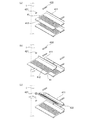
- the storage 4 is provided with a plurality of shelf boards 41 and a plurality of support portions 42 in the storage. Although a three-stage configuration is shown in FIG. 1, any number of stages may be used.
- FIG. 2 the detail of the shelf board 41 and the support part 42 is shown.
- 2A is a perspective view of the shelf board 41 and the support part 42
- FIG. 2B is a plan view and a side view of the shelf board 41
- FIG. 2C shows a state in which the shelf board 41 is supported by the support part 42. .
- the shelf board 41 is a rectangular plate-like member having a substantially L-shaped cross section having a standing surface 411 that rises from a placement surface on which an object to be stored such as a bottle is placed, and an opening 412 on the placement surface. There are multiple.
- the opening 412 is formed in a slit shape that becomes longer in the direction from the end where the standing surface 411 rises to the end facing the end.
- the support part 42 is divided into a front support part 421 and a rear support part 422 which are rod-like members each having a substantially rectangular cross section, and the front support part 421 and the rear support part 422 are arranged on the inner side wall of the storage 4 respectively. Is done.
- the front support part 421 is provided on the front side in the warehouse (door 1f side), and the rear support part 422 is provided on the rear side in the warehouse (on the outlet 1h side). That is, the front support part 421 is provided in the front of the cabinet (on the door 1f side) than the rear support part 422.
- Each of the front support part 421 and the rear support part 422 is provided with the same height on both the left and right side surfaces, and a set of two front support parts 421 and two rear support parts 422 provided with the same horizontal height, A plurality of sets are arranged in the vertical direction on the inner wall of the side surface of the storage 4.
- the rear support part 422 is provided with a notch part 423.
- the notch 423 is supported when the shelf plate 41 is inclined and supported by the front support portion 421 and the rear support portion 422 provided below the front support portion 421.
- the inclination angle of the shelf board 41 is fixed by catching the rising portion of the standing surface 411. Therefore, the notch 423 is appropriately formed in a shape in which the inclination of the shelf board 41 is stable as shown in FIG.
- the lowermost support portion 42 does not need to be divided into the front support portion 421 and the rear support portion 422, and may be provided with the notch portion 423 on the rear side.
- the front support portion 421 is designed to taper at an angle along the inclination of the shelf plate 41 as shown in FIG. 2C so that the contact portion of the front support portion 421 with the shelf plate 41 becomes a surface. May be.
- FIG. 3A shows a state in which the shelf board 41 is supported horizontally by the support portion 42.
- a plurality of sets of two front support portions 421 and two rear support portions 422 provided so that the horizontal height of the upper surface is the same are provided on the inner side wall of the storage 4. .
- the bottom surface of the shelf board 41 is supported by the upper surface of the support portion 42 thus provided.
- the shelf board 41 is installed so that the standing surface 411 is positioned in the interior depth direction, and the opening 412 becomes longer in the depth direction.
- the support part like the front support part 421 that is provided in the front of the cabinet and supports the shelf board 41 horizontally is called a front horizontal support part.
- FIG. 3B shows the time when the shelf board 41 is removed from the support portion 42 from the state of FIG. 3A, and the shelf board 41 is pulled out in the direction of the arrow in the figure (from the back in the storage 4 to the front side).
- the rising portion of the standing surface 411 of the removed shelf board 41 is inserted into the cutout portion 423 of the rear support portion 422 and provided above the rear support portion 422.
- the front support portion 421 supports the front portion of the removed shelf board 41 (the periphery of the end portion facing the end portion where the standing surface 411 rises on the placement surface).
- the shelf board 41 is supported in the state which inclined to the back in the store
- the support portion such as the front support portion 421 that supports the shelf board 41 so as to incline the storage object rearward in the store is provided in the front of the store, and the front tilt support unit. Call it.
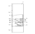
- FIG. 4 the principal part sectional drawing of the storage 4 when the shelf board 41 is made to incline is shown.
- the bottle can be stored in an inclined state on the shelf 41, and the space in the depth direction required for storage can be made smaller than when the bottle is tilted horizontally.
- the shelf board 41 in 4 can also store a bottle effectively.
- the refrigerator is originally shallow in the refrigerator, bottles that could not be stored in the shelf board 41 can be stored.
- the opening 412 even when the shelf board 41 is in an inclined state, the cool air blown out from the outlet 1 h reaches the near side in the storage 4 without being blocked, and the cooling performance is not impaired.
- the opening 412 is long in the depth direction and parallel to the axial direction of the bottle placed on the shelf board 41, the tilted bottle can be prevented from falling.
- the bottles can be effectively stored even in the shelf board 41 in the storage 4. Further, the bottle can be easily stored and taken out.
- a cooling air passage can be secured by the opening 412 to maintain the same cooling performance as usual, and the bottle can be prevented from falling during storage.
- a movable part is not required, it is low-cost and has high robustness.
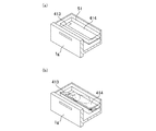
- FIG. 5 the detail of the shelf board 41 with which the storage 4 of the refrigerator which concerns on Embodiment 2 of this invention is equipped is shown. Since the second embodiment is different from the first embodiment only in the shelf board 41 and the support section 42, the description of the configuration other than the shelf board 41 and the support section 42 will be omitted as appropriate.
- 5A is a perspective view of the shelf board 41
- FIG. 5B is a plan view of the shelf board 41
- FIG. 5C is an enlarged cross-sectional view of the notch 415.
- the shelf plate 41 includes an upper plate 413 and a lower plate 414, and the upper plate 413 includes a front upper plate 413a and a rear upper plate 413b.
- the upper plate 413 and the lower plate 414 are rectangular plate-like members having the same size, and their end portions are rotatably supported by hinges or the like.
- a lower upper plate 413b and a rear upper plate 413b of the upper plate 413 are rotatably supported by a lower plate 414 and a hinge.
- the rear upper plate 413b and the front upper plate 413a are rotatably supported by a hinge and the like.
- the movement axis is parallel to the rotation axes of the upper plate 413 and the lower plate 414.
- the front upper plate 413a is provided with an opening 412a
- the rear upper plate 413b is provided with an opening 412b.
- the opening 412b is connected to the rear upper plate 413b from the rotation support portion of the rear upper plate 413b and the lower plate 414. It is formed in a slit shape that becomes longer in the direction toward the rotation support portion with the front upper plate 413a.
- the opening 412a is formed at a position obtained by extending the opening 412b in the length direction.
- the lower plate 414 includes a plurality of groove-shaped cutouts 415 on one surface (upper surface) that contacts the upper plate 413.
- the notch portion 415 has an end portion in a direction facing the rotation shaft in the front upper plate 413a when the rear upper plate 413b and the front upper plate 413a are rotated.
- the inclination angle of the upper plate 413 is fixed. Since a plurality of the notches 415 are provided in parallel with the groove shape, the inclination angle can be adjusted.
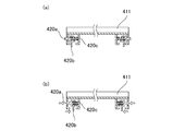
- FIG. 6A shows a state in which the shelf board 41 is supported horizontally by the support portion 42.
- the support part 42 in this Embodiment 2 may be a support part of a shelf plate as provided in a normal refrigerator, for example, a rod-shaped member arranged on the inner wall of the side surface in the storage 4 It is not necessary to divide like the support part 42 of the form 1 or to provide a notch.
- the support portion 42 is a rear support portion and also a front horizontal support portion that horizontally supports the shelf board 41.
- the shelf board 41 is installed such that the front upper plate 413a is positioned in the front side of the cabinet and the rear upper plate 413b is positioned in the back direction of the cabinet, and the notch 415 becomes a groove in the width direction of the cabinet, The part 412b becomes longer in the depth direction.
- FIG. 6B shows a state where the upper plate 413 is lifted from the state of FIG. Subsequently, as shown in FIG. 6C, the front upper plate 413 a is bent and hooked on the notch 415 of the lower plate 414. Thereby, the back upper board 413b is supported in the state which inclined to the back in the store
- the notch part 415 which supports the back upper plate 413b by inclining back in the warehouse is a front inclination support part provided in the front in the warehouse.
- FIG. 7 shows a cross-sectional view of the main part of the storage 4 when the rear upper plate 413b is inclined.
- the bottle can be stored in an inclined state on the rear upper plate 413b, and the space in the depth direction required for storage can be made smaller than when the bottle is tilted horizontally.
- Bottles can also be stored effectively in the shelf 41 in the storage 4. In particular, if the refrigerator is originally shallow in the refrigerator, bottles that could not be stored in the shelf board 41 can be stored. Further, by providing the openings 412a and 412b, even when the upper plate 413 is inclined, the cool air blown out from the air outlet 1h reaches the near side in the storage 4 without being blocked, and the cooling performance is not impaired. Furthermore, since the opening 412b is long in the depth direction and parallel to the axial direction of the bottle placed on the upper plate 413, the tilted bottle can be prevented from falling.
- bottles can be effectively stored even on the shelf board 41 in the storage 4. Further, the bottle can be easily stored and taken out.
- a cooling air passage is secured by the openings 412a and 412b to maintain the same cooling performance as usual, and the bottle can be prevented from falling during storage.
- the versatility is high, and it is not necessary to remove the shelf board 41 and change the shelf position, so that deformation is easy. Since no opening is provided in the lower plate 414, there is an effect that even if water is spilled on the shelf plate 41, water does not leak to the lower stage.
- FIG. 8 the detail of the shelf board 41 and the support part 42 with which the storage 4 of the refrigerator which concerns on Embodiment 3 of this invention is provided is shown. Since the third embodiment is different from the first embodiment only in the shelf board 41 and the support section 42, the description of the configuration other than the shelf board 41 and the support section 42 will be omitted as appropriate.
- 8A is a perspective view of the shelf board 41
- FIG. 8B is a plan view of the shelf board 41
- FIG. 8C shows a state in which the shelf board 41 is supported by the support portion 42.
- the shelf plate 41 includes an upper plate 413 and a lower plate 414, and the upper plate 413 further includes an opening 416 and an engaging portion 418.
- the upper plate 413 is formed by hollowing out a part of a rectangular plate-like member so that the end surface is corrugated to provide an opening 416.
- an engagement portion 418 is provided at the tip of the end portion 417 formed on both side surfaces of the opening 416 by hollowing out.
- the engaging part 418 is a rod-shaped member, for example.
- the lower plate 414 is a quadrangular plate-like member and includes engaged portions 419 that engage with the engaging portions 418 at both ends.
- the engaged portion 419 is, for example, a plurality of grooves.
- the lower plate 414 is raised in the shape of the opening 416 at the center. This is to prevent a step from being generated on the upper surface of the shelf 41 serving as a mounting surface in a state where the entire shelf 41 is supported horizontally as described later.
- the support part 42 includes a normal support part 424 and a bottle storage support part 425.
- the normal support portion 424 is a rod-like member having one surface disposed behind the side wall in the storage 4 and is provided in a plurality of stages at the same height on both side surfaces.
- the bottle storage support portion 425 is a short bar-shaped member having one surface arranged in front of the side wall in the storage 4 and is provided in a plurality of stages at the same height on both side surfaces.
- the lowermost bottle storage support part 425 is provided between the lowermost normal support part 424 and the next normal support part 424 in front of the side wall in the storage 4.
- the N-th stage bottle storage support part 425 from the bottom (N is a natural number of 1 or more) includes an N-th stage normal support part 424 and a (N + 1) -th stage normal support part 424 from the bottom. Provided in between.
- the upper plate 413 is supported by the bottle storage support portion 425 and is inclined to the back of the interior. At this time, the inclination angle can be adjusted depending on which position of the plurality of grooves of the engaged portion 419 the engaging portion 418 is engaged with.
- FIG. 9A shows a state where the shelf board 41 is horizontally supported by the N-th normal support portion 424 from the bottom.
- the normal support portion 424 is a rear support portion and also a front horizontal support portion that supports the shelf board 41 horizontally.
- the shelf board 41 is installed so that the opening part 416 and the edge part 417 may be located in the back of a store
- FIG. 9B shows a state in which the upper plate 413 has been lifted from the state of FIG. Subsequently, as shown in FIG. 9C, the angle of inclination of the upper plate 413 is adjusted by engaging the engaging portion 418 of the upper plate 413 with the engaged portion 419 of the lower plate 414 from below.
- a bottle storage support portion 425 provided between the N-th normal support portion 424 and the (N + 1) -th normal support portion 424 from the bottom supports the front portion of the upper plate 413 in the cabinet.
- the upper board 413 is supported in the state which inclined to the back in the store
- the bottle storage support portion 425 that supports the upper plate 413 by tilting backward in the cabinet is a forward tilt support portion provided in the front of the cabinet.
- FIG. 10 the principal part sectional drawing of the storage 4 when the upper board 413 is inclined is shown.
- the bottle can be stored in an inclined state on the upper plate 413, and the space in the depth direction required for storage can be made smaller than when the bottle is tilted horizontally.
- the shelf board 41 in 4 can also store a bottle effectively. In particular, if the refrigerator is originally shallow in the refrigerator, bottles that could not be stored in the shelf board 41 can be stored.
- the opening 416 forms a space between the upper plate 413 and the lower plate 414 when the upper plate 413 is inclined, so that the upper plate 413 is inclined, The cold air blown out from the outlet 1h reaches the front of the storage 4 without being blocked, and the cooling performance is not impaired.
- bottles can be effectively stored even on the shelf board 41 in the storage 4. Further, the bottle can be easily stored and taken out. Further, the cooling air passage can be secured by the opening 416 and the cooling performance that is not different from the normal can be maintained.
- the opening 416 when the upper plate 413 is in a horizontal state, the opening 416 is blocked, so that even if water is spilled on the shelf plate 41, the upper plate 413 does not leak to the lower stage. Since it is not necessary to move all the shelf boards 41 only by moving, there exists an effect that a deformation
- Embodiment 4 FIG. 11 the detail of the shelf board 41 and the support part 42 with which the storage 4 of the refrigerator which concerns on Embodiment 4 of this invention is equipped is shown.
- a lock mechanism 420 is provided at each of two side end portions intersecting with an end portion where the standing surface 411 rises.
- the fourth embodiment includes a mounting hole 426 in place of the front support portion 421 of the first embodiment.
- FIG. 11A is a perspective view of the shelf board 41 and the support portion 42
- FIG. 11B is a plan view and a side view of the shelf board 41.
- the shelf board 41 is a plate-like member having a substantially L-shaped cross section including a lock mechanism 420 in addition to the standing surface 411 and the opening 412 shown in the first embodiment.
- the support part 42 includes a mounting hole 426 and the rear support part 422 shown in the first embodiment.
- the mounting hole 426 is a recess provided in the inner wall of the side surface of the storage 4 and is provided in a plurality of arcs in front of the rear support 422 (on the door 1f side).
- FIG. 12 shows details of the lock mechanism 420.
- the lock mechanism 420 includes a convex portion that engages with the attachment hole 426, and is a mechanism that enables switching between protrusion and protrusion release of the convex portion.
- the lock mechanism 420 includes a lock pin 420a, a knob 420b, and a protruding spring 420c.
- the lock pin 420a and the knob 420b are integrally formed, and the protruding spring 420c is opposed to the lock pin 420a and the knob 420b that are integrally formed at one end with the fixed portion of the shelf board 41 and the other end.
- FIG. 12A shows a state where the protruding spring 420c is in a natural length state and the lock pin 420a is protruding.
- the protruding lock pin 420a is engaged with the mounting hole 426, whereby the shelf board 41 is supported.
- FIG. 12B when the knob 420b is slid by applying a force in the direction of the arrow in the figure, the lock pin 420a also slides integrally, the protruding spring 420c contracts, and the lock pin 420a The protrusion is released.
- the force applied in the direction of the arrow in FIG. 12 (b) is released, the protruding spring 420c is extended by the reaction, and the lock pin 420a and the knob 420b are slid in the direction opposite to the arrow, and again in the state of FIG. 12 (a).
- the operation when the shelf 41 is supported by the support 42 while the shelf 41 is inclined from the state where the shelf 41 is horizontally supported by the support 42 will be described with reference to FIG.
- the lock pin 420a Engage.
- the lock mechanism 420 is positioned one by one on the left and right in the front of the inside of the inside end of the shelf board 41. From this state, the knob 420b is slid to release the protrusion of the lock pin 420a, and the shelf board 41 is lifted.
- the lock pin 420a is protruded at the position of any one of the mounting holes 426 provided in a plurality of arcs above the mounting holes 426 that have maintained the shelf plate 41 horizontally, and both are engaged. Let them support.
- the rising portion of the standing surface 411 is inserted into the cutout portion 423 of the rear support portion 422.
- the shelf board 41 is supported in the state which inclined to the back in the store
- a plurality of mounting holes 426 are provided in an arc shape, and the inclination angle of the shelf board 41 can be arbitrarily adjusted by the holes engaged with the lock pins 420a.
- bottles can be effectively stored even on the shelf board 41 in the storage 4. Further, the bottle can be easily stored and taken out.
- a cooling air passage can be secured by the opening 412 to maintain the same cooling performance as usual, and the bottle can be prevented from falling during storage. Further, as compared with the first embodiment, it is not necessary to remove the shelf board 41 and change the shelf position, so that the deformation is easy and the inclination angle of the shelf board 41 can be adjusted.
- FIG. 14 the detail of the shelf board 41 and the support part 42 with which the storage 4 of the refrigerator which concerns on Embodiment 5 of this invention is equipped is shown.
- the locking mechanism shown in the fourth embodiment at the end portion that intersects the side end portion of the upper plate 413, that is, the end portion that faces the corrugated end portion. 420 is provided at both ends.
- the fifth embodiment is provided with the mounting holes 426 shown in the fourth embodiment in place of the bottle storage support portion 425 of the third embodiment.
- FIG. 14A is a perspective view of the shelf board 41 and the mounting hole 426
- FIG. 14B is a plan view of the shelf board 41.
- the shelf board 41 is provided with the lock mechanism 420 on the upper board 413 shown in the third embodiment.
- the support part 42 includes a mounting hole 426 and the normal support part 424 shown in the third embodiment.
- the attachment holes 426 are concave portions provided on the inner wall of the side surface of the storage 4 and are provided in a plurality of arc shapes.
- the N-th mounting hole 426 from the bottom includes the N-th normal support portion 424 from the bottom and the (N + 1) -th normal support from the bottom. Provided between the unit 424 and the unit 424.
- the shelf board 41 is supported only by the normal support portion 424.
- the lock mechanism 420 is positioned one by one on the left and right in the front of the upper end of the upper plate 413.
- the normal support portion 424 is a rear support portion and also a front horizontal support portion that supports the shelf board 41 horizontally. From this state, the upper plate 413 is lifted and the knob 420b is slid to release the protrusion of the lock pin 420a.
- the attachment hole 426 that supports the upper plate 413 by inclining rearward in the interior is a forward inclined support portion provided in the front of the interior.
- the bottles can be effectively stored even on the shelf board 41 in the storage 4. Further, the bottle can be easily stored and taken out.
- a cooling air passage can be secured to maintain the same cooling performance as usual.
- the opening 416 of the upper plate 413 is blocked, so that water does not leak to the lower stage even if water is spilled on the shelf plate 41. Since only the upper plate 413 needs to be moved and it is not necessary to move all the shelf plates 41, there is an effect that the tilt angle can be easily adjusted and the tilt angle can be adjusted.
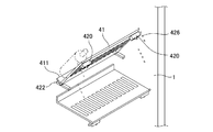
- FIG. 16 the perspective view of the shelf board 41 with which the storage 4 of the refrigerator which concerns on Embodiment 6 of this invention is equipped is shown.
- the shelf board 41 is a rectangular plate-like member, and includes a recess 43 and a bending member 44.
- the curved member 44 is a member in which two straight columns 441 and a curved curved portion 442 are integrally formed. Both ends of the curved member 44 are rotatably supported by hinges or the like on the side surface of the shelf board 41.
- the shelf board 41 is installed on the support portion 42 so that the rotation axis of the bending member 44 is parallel to the interior width direction of the storage 4 and the bending member 44 is disposed in the front of the interior of the storage. .
- FIG. 16 a state when the bending member 44 is tilted is shown in the lower shelf board 41.
- the concave portion 43 is a concave portion that is formed long in the width direction of the storage 4 on the upper surface of the shelf board 41.
- the bending member 44 is rotated and tilted, the bending member 44 is stored.
- the state when the bending member 44 is raised is shown in the upper shelf 41.
- the bending member 44 is raised by rotating in the direction of the arrow in FIG. 16 (around the interior width direction).
- the bending member 44 is installed so as to be fixed at an arbitrary angle by a known technique.
- the bending member 44 is curved in a waveform, and when the bottle is placed in an inclined state by the bending member 44, it functions as a bottle overturn prevention mechanism. Further, when the bending member 44 is raised, a space is secured between the bending member 44 and the top surface of the shelf board 41, so that the cold air blown from the outlet 1h reaches the front of the storage 4 without being blocked. Cooling performance is not impaired.
- the curved member 44 on which the bottle is placed in an inclined state can be referred to as a placement surface. Therefore, the space secured between the curved member 44 and the top surface of the shelf 41 is an opening in the placement surface. Can do. Moreover, it can be said that the hinge etc. which support the bending member 44 which the shelf board 41 has so that a to-be-contained object may incline back in a store
- the bending member 44 may be realized by forming a metal material such as a wire into a rod shape or a line shape, or may be formed by plastic molding other than metal as long as the bottle can be held.
- the support part 42 in this Embodiment 6 may be a support part of a shelf plate as provided in a normal refrigerator, for example, a rod-shaped member having one surface arranged on the side wall in the storage 4. It is not necessary to divide like the support part 42 of the form 1 or to provide a notch.
- the support portion 42 is a rear support portion and also a front horizontal support portion that horizontally supports the shelf board 41.
- the bottles can be effectively stored even on the shelf board 41 in the storage 4. Further, the bottle can be easily stored and taken out.
- the cooling air passage is secured to maintain the same cooling performance as usual, and the corrugated curved member 44 can prevent the bottle from falling during storage.
- since there is no opening other than the space formed between the bending member 44 and the top surface of the shelf board 41 even if water spills on the shelf board 41, water does not leak to the lower stage. Further, it is only necessary to move the bending member 44, and it is not necessary to move all the shelf boards 41, so that deformation is easy, and there is an effect that it can be realized at low cost by using a wire.
- Embodiment 7 FIG.
- each configuration in which the bottles shown in the first to sixth embodiments are inclined with the shelf board 41 is made into a tray type suitable for a slide-type drawer storage such as the storage 5 in FIG. It is developed.
- FIG. 17 shows the tray 51 provided in the drawer-type storage 5 with the shelf board 41 shown in the third embodiment arranged thereon.
- the tray 51 is a box-shaped container whose one surface (upper surface) is open.
- the upper plate 413 is in a horizontal state.
- FIG. 17B shows the state in which the upper plate 413 is inclined by the same operation as that shown in the third embodiment.
- the bottom surface of the tray 51 corresponds to the normal support portion 424
- the upper end portion of the front surface of the tray 51 corresponds to the bottle storage support portion 425.
- a normal support portion 424 and a bottle storage support portion 425 may be separately provided on the side surface inside the tray 51.
- FIG. 17 shows the configuration of the third embodiment expanded to a tray type, but it has already been described that the configurations of the embodiments other than the third embodiment may be expanded to a tray type. It is as follows.
- the effects described in the first to sixth embodiments can be obtained even in the drawer-type storage 5.
- the refrigerator according to the present invention can be used to store a bottle of beverage or the like in the warehouse because the inside of the warehouse can be changed to a form in which the bottle can be easily stored without impairing the cooling performance.
Landscapes
- Physics & Mathematics (AREA)
- Thermal Sciences (AREA)
- Engineering & Computer Science (AREA)
- Chemical & Material Sciences (AREA)
- Combustion & Propulsion (AREA)
- Mechanical Engineering (AREA)
- General Engineering & Computer Science (AREA)
- Cold Air Circulating Systems And Constructional Details In Refrigerators (AREA)
- Devices That Are Associated With Refrigeration Equipment (AREA)
- Freezers Or Refrigerated Showcases (AREA)
Abstract
Description
また、特許文献2には、設けられた商品陳列棚において傾斜状態と水平状態とを切換えて使用可能としたショーケースが開示されている。
また、特許文献3には、棚板を取り外ししやすくするために、棚板を支持するレールの中間部に切欠きを設けた冷蔵庫が開示されている。
ドアポケットでなく、庫内の棚板でボトルを収納する場合は、ボトルを倒して寝かせた状態で収納する必要があるため、開封した牛乳等の紙パック容器は収納することができない。また、奥行きが浅い冷蔵庫では、1.5L等の高さがあるボトルは棚板からはみ出してしまい、収納することができない。
このため、棚板での収納スペースは空いているものの、飲料のボトルやパック等が保存できるドアポケットは一杯になっているという状況が生じ、庫内を有効に使えないという課題があった。
庫内の棚板を上記特許文献に開示される手法で傾斜させた場合は、庫内奥面から搬送される冷気が庫内手前まで届かず、傾斜させた各棚板の底部に留まってしまい、効果的に冷却できなくなるという課題があった。
実施の形態1.
図1に、本発明の実施の形態1に係る冷蔵庫の側面方向からみた断面図を示す。本発明の実施の形態1に係る冷蔵庫は、一面(前面)が開口した箱型の本体1内に、複数に区画された貯蔵庫を備えている。
これら複数に区画された貯蔵庫は、上部より、例えば冷凍室として利用される貯蔵庫2、例えば製氷室として利用される貯蔵庫3、冷蔵室として利用される貯蔵庫4、例えば野菜室として利用される貯蔵庫5である。貯蔵庫2と貯蔵庫3との間は壁1aで、貯蔵庫3と貯蔵庫4との間は壁1bで、貯蔵庫4と貯蔵庫5との間は壁1cでそれぞれ仕切られる。
図2に、棚板41と支持部42の詳細を示す。図2(a)は棚板41と支持部42の斜視図、(b)は棚板41の平面図と側面図、(c)は支持部42で棚板41を支持する様子を示している。
前方支持部421と後方支持部422はそれぞれ、左右両側面において同じ高さで備えられ、水平高さ同じに備えられた2つの前方支持部421と2つの後方支持部422とを一組として、上下方向に複数組並べて貯蔵庫4の側面内壁に備えられる。
切り欠部423は、図2(c)に示すように、前方支持部421と該前方支持部421の下方に備えられた後方支持部422とで棚板41を傾斜させて支持する際に、立ち面411の立ち上がり部が引っ掛かることで、棚板41の傾斜角度を固定する。従って切り欠部423は、図2(c)のように棚板41の傾きが安定する形状に適宜形成される。
なお、最下段の支持部42は、前方支持部421と後方支持部422とに分割する必要はなく、切り欠部423を後方に備えていればよい。
また、前方支持部421の棚板41との当接部分が面となるように、図2(c)のように棚板41の傾斜に沿った角度で先細りするように前方支持部421を設計してもよい。
図3(a)に、支持部42により棚板41が水平に支持されている状態を示す。
上記したように、貯蔵庫4の側面内壁には、上面の水平高さが同じになるように備えられた2つの前方支持部421と2つの後方支持部422の組が、複数組備えられている。
このように備えられた支持部42の上面で棚板41の底面を支持する。このとき、棚板41は、立ち面411が庫内奥方向に位置するように設置され、開口部412は奥行き方向に長くなる。
なお、このように、庫内前方に設けられて、棚板41を水平に支持している前方支持部421のような支持部を、前方水平支持部と呼ぶ。
続いて、図3(c)に示すように、取り外した棚板41の立ち面411の立ち上がり部を後方支持部422の切り欠部423に差し込むとともに、該後方支持部422よりも上方に備えられた前方支持部421に、取り外した棚板41の前方部分(載置面において立ち面411が立ち上がる端部に対向する端部の周辺)を支持させる。これにより、棚板41が庫内の奥へと傾斜した状態で支持される。
なお、このように、庫内前方に設けられて、被収納物を庫内後方に傾斜させるように、棚板41を支持している前方支持部421のような支持部を、前方傾斜支持部と呼ぶ。
ボトルを棚板41上で傾斜させた状態で収納することができ、ボトルを水平に倒したときよりも、収納に必要な奥行き方向のスペースを小さくすることができるので、ドアポケットでなく、貯蔵庫4内の棚板41でも有効にボトルを収納できる。特に、元々庫内の奥行きが浅い冷蔵庫であれば、そもそも棚板41では収納できなかったボトルを収納できる。
また、開口部412を備えることにより、棚板41が傾斜状態になっても、吹き出し口1hから吹き出す冷気が、遮られることなく貯蔵庫4内の手前まで届き、冷却性能が損なわれない。さらに、開口部412は奥行き方向に長く、棚板41に置かれるボトルの軸方向と平行になるので、傾斜状態のボトルが転倒するのを防止することができる。
また、開口部412により冷却風路を確保して通常と変わらない冷却性能を保持すると共に、保存中にボトルが倒れることを防止できる。
また、可動部を必要としないため、低コストであり、かつ、高い堅牢性を持つ。
図5に、本発明の実施の形態2に係る冷蔵庫の貯蔵庫4に備えられる棚板41の詳細を示す。この実施の形態2は、棚板41と支持部42においてのみ実施の形態1と異なるので、棚板41と支持部42以外の構成については適宜説明を省略する。
図5(a)は棚板41の斜視図、(b)は棚板41の平面図、(c)は切り欠部415の断面拡大図を示している。
上板413と下板414は同程度の大きさの四角形の板状部材であり、お互いの端部同士がヒンジ等によって回動可能に支持される。下板414とヒンジ等によって回動可能に支持されるのが上板413の後方上板413bであり、この後方上板413bと前方上板413aはヒンジ等によって回動可能に支持され、その回動軸は、上板413と下板414の回動軸と平行となる。
図6(a)に、支持部42により棚板41が水平に支持されている状態を示す。なお、この実施の形態2での支持部42は、通常の冷蔵庫に備えられているような棚板の支持部、例えば一面が貯蔵庫4内の側面内壁に配置された棒状の部材でよく、実施の形態1の支持部42のように分割したり、切り欠を備える必要はない。支持部42は、後方支持部であるとともに、棚板41を水平に支持する前方水平支持部でもある。
このとき、棚板41は、前方上板413aが庫内手前方向に、後方上板413bが庫内奥方向に位置するように設置され、切り欠部415は庫内幅方向の溝となり、開口部412bは奥行き方向に長くなる。
続いて、図6(c)に示すように、前方上板413aを折り曲げて、下板414の切り欠部415に引っ掛ける。これにより、後方上板413bが庫内の奥へと傾斜した状態で支持される。このように後方上板413bを庫内後方に傾斜させて支持する切り欠部415は、庫内前方に設けられた前方傾斜支持部であるといえる。
ボトルを後方上板413b上で傾斜させた状態で収納することができ、ボトルを水平に倒したときよりも、収納に必要な奥行き方向のスペースを小さくすることができるので、ドアポケットでなく、貯蔵庫4内の棚板41でも有効にボトルを収納できる。特に、元々庫内の奥行きが浅い冷蔵庫であれば、そもそも棚板41では収納できなかったボトルを収納できる。
また、開口部412a、412bを備えることにより、上板413が傾斜状態になっても、吹き出し口1hから吹き出す冷気が、遮られることなく貯蔵庫4内の手前まで届き、冷却性能が損なわれない。さらに、開口部412bは奥行き方向に長く、上板413に置かれるボトルの軸方向と平行になるので、傾斜状態のボトルが転倒するのを防止することができる。
また、開口部412a、412bにより冷却風路を確保して通常と変わらない冷却性能を保持すると共に、保存中にボトルが倒れることを防止できる。
また、実施の形態1と比較すると、通常の冷蔵庫に備えられている既存の支持部を利用できるために汎用性が高く、棚板41を取り外して棚位置を変更する必要がないため変形が容易であり、下板414には開口部を設けないので棚板41上で水物がこぼれても下段に水漏れしないという効果がある。
図8に、本発明の実施の形態3に係る冷蔵庫の貯蔵庫4に備えられる棚板41と支持部42の詳細を示す。この実施の形態3は、棚板41と支持部42においてのみ実施の形態1と異なるので、棚板41と支持部42以外の構成については適宜説明を省略する。
図8(a)は棚板41の斜視図、(b)は棚板41の平面図、(c)は支持部42で棚板41を支持する様子を示している。
上板413は、四角形の板状部材を端面が波形となるように一部くり抜いて開口部416を設けたものである。また、くり抜くことで開口部416の両側面に形成される端部417の先端には、係合部418が備えられる。係合部418は、例えば棒状の部材である。
下板414は、四角形の板状部材であり、両端に係合部418と係合する被係合部419が備えらえる。被係合部419は例えば複数の溝である。また、下板414は、中央部が開口部416の形状で盛り上がっている。これは、後述するような棚板41全体が水平に支持される状態において、載置面となる棚板41の上面に段差が生じることがないようにするためである。
最下段のボトル収納用支持部425は、貯蔵庫4内の側面内壁前方に、最下段の通常支持部424と次段の通常支持部424との間に備えられる。同様に、下からN段目(Nは1以上の自然数)のボトル収納用支持部425は、下からN段目の通常支持部424と下から(N+1)段目の通常支持部424との間に備えられる。
図9(a)に、下からN段目の通常支持部424により棚板41が水平に支持されている状態を示す。通常支持部424は、後方支持部であるとともに、棚板41を水平に支持する前方水平支持部でもある。
このとき、棚板41は、開口部416と端部417が、庫内後方に位置するように設置される。
続いて、図9(c)に示すように、上板413の係合部418を下板414の被係合部419に係合させることで上板413の傾斜角度を調整しつつ、下からN段目の通常支持部424と下から(N+1)段目の通常支持部424との間に備えられたボトル収納用支持部425に上板413の庫内手前部分を支持させる。これにより、上板413が庫内の奥へと傾斜した状態で支持される。このように上板413を庫内後方に傾斜させて支持するボトル収納用支持部425は、庫内前方に設けられた前方傾斜支持部であるといえる。
ボトルを上板413上で傾斜させた状態で収納することができ、ボトルを水平に倒したときよりも、収納に必要な奥行き方向のスペースを小さくすることができるので、ドアポケットでなく、貯蔵庫4内の棚板41でも有効にボトルを収納できる。特に、元々庫内の奥行きが浅い冷蔵庫であれば、そもそも棚板41では収納できなかったボトルを収納できる。
また、開口部416により、上板413が傾斜したときに上板413と下板414との間に庫内前後方向に抜ける空間が形成されるので、上板413が傾斜状態になっても、吹き出し口1hから吹き出す冷気が、遮られることなく貯蔵庫4内の手前まで届き、冷却性能が損なわれない。
また、開口部416により冷却風路を確保して通常と変わらない冷却性能を保持することができる。
また、実施の形態1と比較すると、上板413を水平状態にしているときは開口部416が塞がれるので棚板41上で水物がこぼれても下段に水漏れしない、上板413を動かすだけでよく棚板41全てを動かす必要がないため変形が容易であるという効果がある。
図11に、本発明の実施の形態4に係る冷蔵庫の貯蔵庫4に備えられる棚板41と支持部42の詳細を示す。
この実施の形態4は、実施の形態1の棚板41において、立ち面411が立ち上がる端部と交差する2つの側方端部それぞれにおいてロック機構420を備えるものである。
また、この実施の形態4は、実施の形態1の前方支持部421に代えて、取付穴426を備えるものである。
既に説明したように、棚板41は実施の形態1で示した立ち面411、開口部412に加えて、ロック機構420を備える断面略L字型の板状部材である。
取付穴426は、貯蔵庫4の側面内壁に設けられる凹部であり、後方支持部422よりも庫内前方(扉1f側)に、円弧状に複数備えられる。
ロック機構420は、取付穴426に係合する凸部を備え、この凸部の突出と突出解除とを切り替え可能とする機構である。ロック機構420は、例えば図12に示すようにロックピン420a、ツマミ420b、突出しバネ420cを備える。
ロックピン420aとツマミ420bとは一体的に形成されて、突出しバネ420cは一端が棚板41の固定された部位に、他端が一体的に形成されたロックピン420aとツマミ420bに対向する。
図12(b)中の矢印方向に加えた力を解除すると、突出しバネ420cが反動で伸びてロックピン420aとツマミ420bとを矢印と逆方向にスライドさせ、再度図12(a)の状態に戻る。
棚板41を水平に支持させるときは、棚板41を支持する後方支持部422と同じ高さ周辺に円弧状に複数備えられている取付穴426のうち両側面1つずつとロックピン420aとを係合させる。棚板41を支持部42で支持させたとき、ロック機構420は、棚板41の庫内側方端部の庫内前方に左右1つずつ位置する。
この状態から、ツマミ420bをスライドさせてロックピン420aの突出を解除し、棚板41を持ち上げる。
つまり、庫内前方に設けられた取付穴426は、棚板41を水平に支持する前方水平支持部であるとともに、被収納物を庫内後方に傾斜させるように、棚板41を支持する前方傾斜支持部でもある。
取付穴426は円弧状に複数備えられており、ロックピン420aと係合させる穴によって棚板41の傾斜角度を任意に調整することができる。
また、開口部412により冷却風路を確保して通常と変わらない冷却性能を保持すると共に、保存中にボトルが倒れることを防止できる。
また、実施の形態1と比較すると、棚板41を取り外して棚位置を変更する必要がないため変形が容易であり、棚板41の傾斜角度の調整が可能になるという効果がある。
図14に、本発明の実施の形態5に係る冷蔵庫の貯蔵庫4に備えられる棚板41と支持部42の詳細を示す。
この実施の形態5は、実施の形態3の棚板41において、上板413の側方端部つまり波形の端部に対向する端部と交差する端部において実施の形態4で示したロック機構420を両端に備えるものである。
また、この実施の形態5は、実施の形態3のボトル収納用支持部425に代えて、実施の形態4で示した取付穴426を備えるものである。
既に説明したように、棚板41は実施の形態3で示した上板413に、ロック機構420を備えたものである。
取付穴426は、実施の形態4で示したように、貯蔵庫4の側面内壁に設けられる凹部であり、円弧状に複数備えられる。なお、実施の形態3で示したボトル収納用支持部425と同じく、下からN段目の取付穴426は、下からN段目の通常支持部424と下から(N+1)段目の通常支持部424との間に備えられる。
棚板41を水平に支持させるときは、棚板41を通常支持部424のみで支持する。このとき、ロック機構420は、上板413の庫内側方端部の庫内前方に左右1つずつ位置する。通常支持部424は、後方支持部であるとともに、棚板41を水平に支持する前方水平支持部でもある。
この状態から、上板413を持ち上げて、ツマミ420bをスライドさせてロックピン420aの突出を解除する。
続いて、上板413の係合部418を下板414の被係合部419に係合させつつ、棚板41を水平状態に支持していた通常支持部424より上方の取付穴426のうち任意の1つの穴の位置でロックピン420aを突出させ、両者を係合させて支持させる。これにより、上板413が庫内の奥へと傾斜した状態で支持される。このように上板413を庫内後方に傾斜させて支持する取付穴426は、庫内前方に設けられた前方傾斜支持部であるといえる。
また、冷却風路を確保して通常と変わらない冷却性能を保持することができる。
また、実施の形態1と比較すると、上板413を水平状態にしているときは上板413の開口部416が塞がれるので棚板41上で水物がこぼれても下段に水漏れしない、上板413を動かすだけでよく棚板41全てを動かす必要がないため変形が容易である、傾斜角度の調整が可能になるという効果がある。
図16に、本発明の実施の形態6に係る冷蔵庫の貯蔵庫4に備えられる棚板41の斜視図を示す。
棚板41は、四角形の板状部材であり、凹部43と、湾曲部材44とを備える。
湾曲部材44は、直線状の2つの支柱441と波形に湾曲した湾曲部442とが一体的に形成された部材であり、棚板41の側面においてヒンジ等により両端が回動可能に支持されて備えられる。湾曲部材44の回動軸が、貯蔵庫4の庫内幅方向と平行になるように、また、湾曲部材44が庫内前方に配置されるように、棚板41は支持部42に設置される。
一方、湾曲部材44を起こしたときの状態を上段の棚板41に示している。図16中矢印の方向(庫内幅方向回り)に回動させることで湾曲部材44は起き上がる。湾曲部材44は、周知の技術により、任意の角度にて固定が可能なように設置される。
また、被収納物を庫内後方に傾斜させるように、棚板41が有する湾曲部材44を支持するヒンジ等は、前方傾斜支持部であるといえる。
また、この実施の形態6での支持部42は、通常の冷蔵庫に備えられているような棚板の支持部、例えば一面が貯蔵庫4内の側面内壁に配置された棒状の部材でよく、実施の形態1の支持部42のように分割したり、切り欠を備える必要はない。支持部42は、後方支持部であるとともに、棚板41を水平に支持する前方水平支持部でもある。
また、冷却風路を確保して通常と変わらない冷却性能を保持すると共に、波形の湾曲部材44により保存中にボトルが倒れることを防止できる。
また、実施の形態1と比較すると、湾曲部材44と棚板41上面との間に形成される空間以外には開口部がないので棚板41上で水物がこぼれても下段に水漏れしない、湾曲部材44を動かすだけでよく棚板41全てを動かす必要がないため変形が容易である、ワイヤーの使用により安価に実現可能であるという効果がある。
この実施の形態7では、実施の形態1~6で示したボトルを棚板41で傾斜状態にする各構成を、図1の貯蔵庫5のようなスライド式の引出し式貯蔵庫に適したトレイ型に展開したものである。
図17(b)は、実施の形態3で示した動作と同様の動作で上板413を傾斜させた状態のものである。このとき、トレイ51の底面は通常支持部424に、トレイ51の前面の上端部はボトル収納用支持部425にそれぞれ対応する。なお、トレイ51内部の側面に、通常支持部424、ボトル収納用支持部425を別途備えてもよい。
また、図17では、実施の形態3の構成をトレイ型に展開したものを示したが、実施の形態3以外の実施の形態の構成をトレイ型に展開してもよいのは、既に述べたとおりである。
Claims (14)
- 庫内に棚板と前記棚板を支持する支持部とを備える冷蔵庫であって、
前記棚板は、
載置面において開口部を備え、
前記支持部は、
庫内後方に設けられた後方支持部と、
前記棚板を水平に支持するように庫内前方に設けられた前方水平支持部と、
被収納物を庫内後方に傾斜させるように、庫内前方に設けられて前記棚板を支持する前方傾斜支持部とを備えることを特徴とする冷蔵庫。 - 前記棚板は、
庫内後方に前記開口部を有して、前記開口部の両側面で庫内後方側に係合部を備える上板と、
前記係合部と係合する複数の被係合部を備える下板とを備え、
前記前方傾斜支持部は、
前記上板を庫内後方に傾斜させて支持するように設けられたことを特徴とする請求項1記載の冷蔵庫。 - 前記棚板は、
庫内側方端部の庫内前方に、凸部を備えるロック機構を備え、
前記前方傾斜支持部は、
庫内側面に円弧状に複数設けられた取付穴であることを特徴とする請求項1記載の冷蔵庫。 - 前記上板は、
庫内側方端部の庫内前方に、凸部を備えるロック機構を備え、
前記前方傾斜支持部は、
庫内側面に円弧状に複数設けられた取付穴であることを特徴とする請求項2記載の冷蔵庫。 - 前記棚板は、
前記載置面の庫内後方端部から立ち上がる立ち面を備え、
前記開口部は、
庫内奥行き方向に長いスリット状であり、
前記後方支持部は、
切り欠部を備えることを特徴とする請求項1記載の冷蔵庫。 - 前記棚板は、
前記棚板の側面において庫内幅方向回りに回動可能に支持される、波形に湾曲した湾曲部材と、
前記湾曲部材を回動収納可能な凹部とを備え、
前記湾曲部材が回動して立ち上がると、前記湾曲部材と前記棚板上面との間に前記開口部が形成されることを特徴とする請求項1記載の冷蔵庫。 - 前記棚板は、
切り欠部を備える下板と、
前記下板と回動可能に接続される上板とを備え、
前記上板は、
庫内後方端部が前記下板の庫内後方端部と回動可能に接続されて、開口部を有する後方上板と、
庫内後方端部が前記後方上板の庫内前方端部と回動可能に接続されて、開口部を有するとともに、前記切り欠部と係合する前方上板とを備え、
前記前方傾斜支持部は、
前記切り欠部であり、前記後方上板を庫内後方に傾斜させて支持するように設けられたことを特徴とする請求項1記載の冷蔵庫。 - 庫内に更に、上面が開口した箱型のトレイを備える冷蔵庫であって、
前記棚板と前記支持部とは、
前記トレイ内に設けられることを特徴とする請求項1記載の冷蔵庫。 - 庫内に更に、上面が開口した箱型のトレイを備える冷蔵庫であって、
前記棚板と前記支持部とは、
前記トレイ内に設けられることを特徴とする請求項2記載の冷蔵庫。 - 庫内に更に、上面が開口した箱型のトレイを備える冷蔵庫であって、
前記棚板と前記支持部とは、
前記トレイ内に設けられることを特徴とする請求項3記載の冷蔵庫。 - 庫内に更に、上面が開口した箱型のトレイを備える冷蔵庫であって、
前記棚板と前記支持部とは、
前記トレイ内に設けられることを特徴とする請求項4記載の冷蔵庫。 - 庫内に更に、上面が開口した箱型のトレイを備える冷蔵庫であって、
前記棚板と前記支持部とは、
前記トレイ内に設けられることを特徴とする請求項5記載の冷蔵庫。 - 庫内に更に、上面が開口した箱型のトレイを備える冷蔵庫であって、
前記棚板と前記支持部とは、
前記トレイ内に設けられることを特徴とする請求項6記載の冷蔵庫。 - 庫内に更に、上面が開口した箱型のトレイを備える冷蔵庫であって、
前記棚板と前記支持部とは、
前記トレイ内に設けられることを特徴とする請求項7記載の冷蔵庫。
Priority Applications (4)
| Application Number | Priority Date | Filing Date | Title |
|---|---|---|---|
| CN201380077744.7A CN105339746A (zh) | 2013-06-27 | 2013-06-27 | 冰箱 |
| JP2015523750A JPWO2014207862A1 (ja) | 2013-06-27 | 2013-06-27 | 冷蔵庫 |
| PCT/JP2013/067654 WO2014207862A1 (ja) | 2013-06-27 | 2013-06-27 | 冷蔵庫 |
| TW102128211A TW201500707A (zh) | 2013-06-27 | 2013-08-07 | 冰箱 |
Applications Claiming Priority (1)
| Application Number | Priority Date | Filing Date | Title |
|---|---|---|---|
| PCT/JP2013/067654 WO2014207862A1 (ja) | 2013-06-27 | 2013-06-27 | 冷蔵庫 |
Publications (1)
| Publication Number | Publication Date |
|---|---|
| WO2014207862A1 true WO2014207862A1 (ja) | 2014-12-31 |
Family
ID=52141265
Family Applications (1)
| Application Number | Title | Priority Date | Filing Date |
|---|---|---|---|
| PCT/JP2013/067654 WO2014207862A1 (ja) | 2013-06-27 | 2013-06-27 | 冷蔵庫 |
Country Status (4)
| Country | Link |
|---|---|
| JP (1) | JPWO2014207862A1 (ja) |
| CN (1) | CN105339746A (ja) |
| TW (1) | TW201500707A (ja) |
| WO (1) | WO2014207862A1 (ja) |
Cited By (4)
| Publication number | Priority date | Publication date | Assignee | Title |
|---|---|---|---|---|
| CN104880008A (zh) * | 2015-05-18 | 2015-09-02 | 合肥美的电冰箱有限公司 | 冰箱搁架组件和冰箱 |
| JP3206430U (ja) * | 2016-07-05 | 2016-09-15 | 季之 菱沼 | 液体紙容器用トレイ |
| EP3483538A1 (en) * | 2017-11-13 | 2019-05-15 | BSH Hausgeräte GmbH | A present shelf and a refrigerator |
| EP3081885B1 (de) * | 2015-04-16 | 2020-09-30 | BSH Hausgeräte GmbH | Haushaltskühlgerät mit einem fachboden |
Citations (9)
| Publication number | Priority date | Publication date | Assignee | Title |
|---|---|---|---|---|
| JPS52136594U (ja) * | 1976-04-09 | 1977-10-17 | ||
| JPS5485995U (ja) * | 1977-11-30 | 1979-06-18 | ||
| JPS55149189U (ja) * | 1979-04-11 | 1980-10-27 | ||
| JPS55150988U (ja) * | 1979-04-17 | 1980-10-30 | ||
| JPS5949887U (ja) * | 1982-09-27 | 1984-04-02 | 株式会社日立製作所 | 冷蔵庫の可変棚 |
| JPH0949684A (ja) * | 1995-08-07 | 1997-02-18 | Fujitsu General Ltd | 野菜収納容器 |
| JP2000130925A (ja) * | 1998-10-29 | 2000-05-12 | Matsukinrii:Kk | 冷蔵庫 |
| JP2002228352A (ja) * | 2001-01-29 | 2002-08-14 | Toshiba Corp | 冷蔵庫の多機能棚 |
| JP2005331223A (ja) * | 2004-05-18 | 2005-12-02 | Lg Electronics Inc | ワイン冷蔵庫の棚 |
Family Cites Families (8)
| Publication number | Priority date | Publication date | Assignee | Title |
|---|---|---|---|---|
| JPS5962490U (ja) * | 1982-10-20 | 1984-04-24 | 三洋電機株式会社 | 貯蔵庫の棚装置 |
| JPH0327073U (ja) * | 1989-07-26 | 1991-03-19 | ||
| JP2001201251A (ja) * | 2000-01-20 | 2001-07-27 | Gac Kk | 貯蔵庫 |
| CN1191451C (zh) * | 2002-04-25 | 2005-03-02 | 乐金电子(天津)电器有限公司 | 电冰箱的搁架装置 |
| CN1213272C (zh) * | 2002-11-26 | 2005-08-03 | 乐金电子(天津)电器有限公司 | 冰箱的搁板 |
| CN2671427Y (zh) * | 2003-12-16 | 2005-01-19 | 广州万宝集团有限公司 | 多用途置物搁架 |
| CN201583101U (zh) * | 2009-12-31 | 2010-09-15 | 海尔集团公司 | 一种具有酒架的冷藏柜 |
| CN202515047U (zh) * | 2012-03-28 | 2012-11-07 | 深圳市新潮电器有限公司 | 两用型层架 |
-
2013
- 2013-06-27 CN CN201380077744.7A patent/CN105339746A/zh active Pending
- 2013-06-27 JP JP2015523750A patent/JPWO2014207862A1/ja active Pending
- 2013-06-27 WO PCT/JP2013/067654 patent/WO2014207862A1/ja active Application Filing
- 2013-08-07 TW TW102128211A patent/TW201500707A/zh unknown
Patent Citations (9)
| Publication number | Priority date | Publication date | Assignee | Title |
|---|---|---|---|---|
| JPS52136594U (ja) * | 1976-04-09 | 1977-10-17 | ||
| JPS5485995U (ja) * | 1977-11-30 | 1979-06-18 | ||
| JPS55149189U (ja) * | 1979-04-11 | 1980-10-27 | ||
| JPS55150988U (ja) * | 1979-04-17 | 1980-10-30 | ||
| JPS5949887U (ja) * | 1982-09-27 | 1984-04-02 | 株式会社日立製作所 | 冷蔵庫の可変棚 |
| JPH0949684A (ja) * | 1995-08-07 | 1997-02-18 | Fujitsu General Ltd | 野菜収納容器 |
| JP2000130925A (ja) * | 1998-10-29 | 2000-05-12 | Matsukinrii:Kk | 冷蔵庫 |
| JP2002228352A (ja) * | 2001-01-29 | 2002-08-14 | Toshiba Corp | 冷蔵庫の多機能棚 |
| JP2005331223A (ja) * | 2004-05-18 | 2005-12-02 | Lg Electronics Inc | ワイン冷蔵庫の棚 |
Cited By (5)
| Publication number | Priority date | Publication date | Assignee | Title |
|---|---|---|---|---|
| EP3081885B1 (de) * | 2015-04-16 | 2020-09-30 | BSH Hausgeräte GmbH | Haushaltskühlgerät mit einem fachboden |
| CN104880008A (zh) * | 2015-05-18 | 2015-09-02 | 合肥美的电冰箱有限公司 | 冰箱搁架组件和冰箱 |
| JP3206430U (ja) * | 2016-07-05 | 2016-09-15 | 季之 菱沼 | 液体紙容器用トレイ |
| EP3483538A1 (en) * | 2017-11-13 | 2019-05-15 | BSH Hausgeräte GmbH | A present shelf and a refrigerator |
| US10485339B2 (en) | 2017-11-13 | 2019-11-26 | Bsh Hausgeraete Gmbh | Rack and refrigeration appliance |
Also Published As
| Publication number | Publication date |
|---|---|
| CN105339746A (zh) | 2016-02-17 |
| JPWO2014207862A1 (ja) | 2017-02-23 |
| TW201500707A (zh) | 2015-01-01 |
Similar Documents
| Publication | Publication Date | Title |
|---|---|---|
| CN102395849B (zh) | 用于制冷机的滑动搁板 | |
| KR101602215B1 (ko) | 냉장고의 수납 장치 및 이를 구비한 냉장고 | |
| EP2818814B1 (en) | Refrigerator | |
| EP3653979B1 (en) | Refrigerator | |
| US8029081B2 (en) | Refrigerator | |
| AU2012250112B2 (en) | Crisper drawers with rollers and ramp | |
| JP6496419B2 (ja) | 冷蔵庫 | |
| US20080168794A1 (en) | Refrigerator | |
| KR20110040567A (ko) | 분할식 선반을 갖는 냉장고 | |
| WO2014207862A1 (ja) | 冷蔵庫 | |
| US20100175420A1 (en) | Refrigerator | |
| KR101622231B1 (ko) | 냉장고 | |
| KR102043201B1 (ko) | 냉장고 | |
| WO2010100909A1 (ja) | 冷蔵庫 | |
| KR101298070B1 (ko) | 냉장고용 선반 어셈블리 및 그를 구비한 공간 가변형 냉장고 | |
| KR101774101B1 (ko) | 냉장고 선반 | |
| US9222723B2 (en) | Foldable rack for a refrigerator | |
| AU2016400675A1 (en) | Refrigerator | |
| WO2018197220A1 (en) | A household cooling appliance with collapsible shelf | |
| KR100700617B1 (ko) | 냉장고의 접이식 선반 및 이를 구비한 냉장고 | |
| JP3470222B2 (ja) | 棚付移動用冷蔵庫 | |
| JP2004293911A (ja) | 棚装置、および棚装置を備えた冷蔵庫 | |
| KR20140119970A (ko) | 냉장고 | |
| US11709016B2 (en) | Support assembly for an appliance | |
| JP2004020114A (ja) | 冷蔵庫 |
Legal Events
| Date | Code | Title | Description |
|---|---|---|---|
| WWE | Wipo information: entry into national phase |
Ref document number: 201380077744.7 Country of ref document: CN |
|
| ENP | Entry into the national phase |
Ref document number: 2015523750 Country of ref document: JP Kind code of ref document: A |
|
| 121 | Ep: the epo has been informed by wipo that ep was designated in this application |
Ref document number: 13887994 Country of ref document: EP Kind code of ref document: A1 |
|
| NENP | Non-entry into the national phase |
Ref country code: DE |
|
| 122 | Ep: pct application non-entry in european phase |
Ref document number: 13887994 Country of ref document: EP Kind code of ref document: A1 |