WO2014204017A1 - 清掃用具および清掃用具の製造方法 - Google Patents
清掃用具および清掃用具の製造方法 Download PDFInfo
- Publication number
- WO2014204017A1 WO2014204017A1 PCT/JP2014/070384 JP2014070384W WO2014204017A1 WO 2014204017 A1 WO2014204017 A1 WO 2014204017A1 JP 2014070384 W JP2014070384 W JP 2014070384W WO 2014204017 A1 WO2014204017 A1 WO 2014204017A1
- Authority
- WO
- WIPO (PCT)
- Prior art keywords
- cleaning tool
- brush
- cleaning
- region
- base
- Prior art date
- Legal status (The legal status is an assumption and is not a legal conclusion. Google has not performed a legal analysis and makes no representation as to the accuracy of the status listed.)
- Ceased
Links
Images












Classifications
-
- A—HUMAN NECESSITIES
- A47—FURNITURE; DOMESTIC ARTICLES OR APPLIANCES; COFFEE MILLS; SPICE MILLS; SUCTION CLEANERS IN GENERAL
- A47L—DOMESTIC WASHING OR CLEANING; SUCTION CLEANERS IN GENERAL
- A47L13/00—Implements for cleaning floors, carpets, furniture, walls, or wall coverings
- A47L13/10—Scrubbing; Scouring; Cleaning; Polishing
- A47L13/38—Other dusting implements
Definitions
- the present invention relates to a cleaning tool for cleaning an object to be cleaned.
- Japanese Unexamined Patent Application Publication No. 2007-159612 discloses a cleaning article that is attached to a handle and used.
- the cleaning article has a fiber layer and a handle insertion part.
- the handle insertion portion is formed by a fused portion provided in the fiber layer. That is, a fusion insertion portion is formed by fusing predetermined regions of a pair of fiber layers, and a grip insertion portion is formed by opposing the fusion portions of the pair of fiber layers.
- the cleaning article described in Japanese Patent Application Laid-Open No. 2007-159612 has a low degree of freedom in design because the grip insertion portion is formed so that the fused portions formed in the pair of fiber layers face each other.
- the present invention has been made in view of such a point, and an object thereof is to provide a more rational construction technique for a cleaning tool.
- a cleaning tool includes a cleaning sheet and a holder that holds the cleaning sheet.
- the cleaning sheet is configured to extend in both the longitudinal direction defined by the direction in which the holder is inserted into the cleaning sheet and the longitudinal crossing direction defined by the direction intersecting the longitudinal direction.
- the holder has a holding part for holding the cleaning sheet, and a holding part connected to the holding part and held by the user.
- the cleaning sheet includes a brush portion configured to be able to clean an object to be cleaned, a base portion formed by a nonwoven fabric to which the brush portion is connected and whose length in the longitudinal direction is shorter than the brush portion, and the brush portion and the base portion. And an insertion portion that is formed therebetween and into which the holding portion is inserted.
- a hardened portion is formed in the longitudinal region of the brush portion forming the insertion portion.
- the brush portion is formed of a fiber structure.
- This fiber structure can be formed by a fiber assembly of a plurality of fibers having an orientation in a predetermined direction.
- a fiber structure can be formed with a nonwoven fabric.
- the fiber structure can be formed of fibers having heat-welding properties.
- a hardening part can be formed by welding the heat welding fiber in a fiber structure.
- the cured portion can be formed by curing the impregnated body impregnated in the fiber constituent body.
- the cured portion formed in the region extending from the end portion of the brush portion to the end portion of the base portion is formed with a cured portion in the brush portion. It is possible to form a high-rigidity portion having high rigidity compared to a region where there is no region. In this case, the high-rigidity part can prevent the brush part area not held by the holding part from sagging.
- the high-rigidity end region that is the region including the end portion in the longitudinal direction of the high-rigidity portion forms a scraped portion that comes into contact with the object to be cleaned. be able to. With this scraping portion, the user can scrape dirt, dust, and the like to be cleaned.
- the hardened portion formed in the region extending between both end portions of the base portion has a low friction portion having a lower coefficient of friction than the base portion. Can be formed. By this low friction portion, the holding portion can be smoothly inserted into the insertion space.
- the brush portion can have a first brush region in which the hardened portion is formed and a second brush region in which the hardened portion is not formed.
- the brush portion when the brush portion is formed of a fiber assembly, the entanglement of the respective fiber assemblies in the first brush region and the second brush region can be reduced.
- the brush portion can be provided on one surface of the base portion.
- the brush portion can be provided on one surface and the other surface of the base portion.
- the manufacturing method of the cleaning tool in this invention is related with the manufacturing method of the cleaning tool which has a cleaning sheet and the holding tool holding a cleaning sheet.
- the cleaning sheet has a base portion and a brush portion bonded to the base portion, and is held between the step of forming a cured portion on the brush portion, the step of connecting the base portion to the brush portion, and the brush portion and the base portion. Forming an insertion part for inserting the part.
- the brush portion can be formed of a fiber structure.
- the fiber structure can be formed by a fiber assembly of a plurality of fibers having an orientation in a specific direction.
- a fiber structure can be formed with a nonwoven fabric.
- the fiber structure can be formed of fibers having heat-welding properties.
- a hardening part can be formed by welding the heat welding fiber in a fiber structure.
- the cured portion can be formed by curing the impregnated body impregnated in the fiber constituent.
- the cleaning objects to be cleaned using this cleaning tool A include indoor, outdoor, and outdoor surfaces to be cleaned (floor surface, wall surface, window, ceiling surface, outer wall surface, furniture, etc.) Surface, clothes, curtains, bedding, lighting, home appliances, etc.) and surfaces to be cleaned in each component of the human body.
- These various surfaces to be cleaned may be configured as a flat surface, or may be configured as a curved surface, an uneven surface, or a step surface.
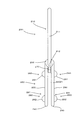
- the cleaning tool A includes a cleaning body holder 200 and a cleaning body 100.
- the cleaning body holder 200 is detachably attached to the cleaning body 100 and is configured to hold the cleaning body 100.
- This cleaning tool A is an example of the “cleaning tool” in the present invention.
- This cleaning body holder 200 is an example of the “holder” in the present invention.
- This cleaning body 100 is an example of the “cleaning sheet” in the present invention.
- the cleaning body 100 is configured to extend in both the longitudinal direction Y and the longitudinal intersecting direction X defined by the direction intersecting the longitudinal direction Y.
- the longitudinal direction Y is defined by a direction parallel to the direction in which the cleaning body holder 200 is inserted into the cleaning body 100.
- the direction in which the cleaning body holder 200 is inserted into the cleaning body 100 is the insertion direction Y1.
- the direction opposite to the insertion direction Y1 is the drawing direction Y2.
- a direction intersecting with each of the longitudinal direction Y and the longitudinal crossing direction X is a thickness direction Z.
- “intersection” means “orthogonal”.
- This longitudinal direction Y is an example of the “longitudinal direction” in the present invention.
- This longitudinal cross direction X is an example of the “longitudinal cross direction” in the present invention.
- the cleaning body 100 further extends in the thickness direction Z, which is a direction defined by the direction intersecting both the longitudinal direction Y and the longitudinal intersecting direction X.
- the cleaning body 100 has one surface 100Z1 and the other surface 100Z2 facing the one surface 100Z1.
- the other surface 100Z2 is directed to the cleaning target side.
- the cleaning body holder 200 is mainly composed of a handle part 210 and a cleaning body holding part 220.
- the handle part 210 is a member that is formed in a long shape and is held by the user during cleaning.
- the handle part 210 has a handle 211 and a handle joint part 212.
- the handle joint portion 212 is joined to the connecting portion 230 of the cleaning body holding portion 220.
- the handle 211 is formed in a long shape extending from the handle joint portion 212.
- the handle portion 210 is an example of the “gripping portion” in the present invention.
- the cleaning body holding unit 220 is an example of the “holding unit” in the present invention.
- the cleaning body holding part 220 is a member for holding the cleaning body 100, which is molded from a resin material.
- the cleaning body holding part 220 is mainly composed of two holding members 221 formed in a long shape, a convex part 260, a pressing plate 270, and the like.
- the cleaning body holder 220 is made of polypropylene (PP).
- maintenance part 220 can select the resin material which has flexibility suitably.
- polyethylene (PE), polyethylene terephthalate (PET), acrylonitrile-butadiene-styrene resin (ABS), and polyester-based thermoplastic elastomer can be used.
- the cleaning body holding part 220 has a first surface 220Z1 and a second surface 220Z2 facing the first surface 220Z1.
- the second surface 220Z2 is a surface that is directed to the cleaning target during the cleaning operation.
- the holding member 221 extends from the connecting portion 230 in a direction opposite to the direction in which the handle 211 extends. That is, the holding member 221 includes a connecting portion 230, a tip portion 240, and an intermediate portion 250 that extends from the connecting portion 230 toward the tip portion 240.
- the front end portions 240 of the two holding members 221 are free ends.
- the convex part 260 is provided in the outer side direction in the intermediate part 250.
- the convex portion 260 includes a first convex portion 261 provided on the connecting portion 230 side and a second convex portion 262 provided on the distal end portion 240 side.
- the pressing plate 270 is formed so as to protrude from the connecting portion 230.
- the holding plate 270 is formed between the pair of holding members 221 so as to extend in parallel with the holding member 221.
- the presser plate 270 is configured as a plate-like member that is curved so as to be convex downward, and further includes a locking projection (not shown) on the lower surface.
- the cleaning body 100 is a sheet-like cleaning body having a dirt collecting function for collecting dirt such as dust to be cleaned. As shown in FIGS. 4 to 7, the cleaning body 100 is formed in a rectangular shape in plan view.
- This cleaning body 100 is a disposable type that is used once as a guide, or a disposable type that is replaced with multiple uses as a guide while holding dust and dust removed from the surface to be cleaned. It may be of a type that can be used repeatedly after washing or the like.
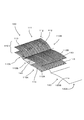
- FIG. 3 is an exploded perspective view showing each component of the cleaning body 100 according to the embodiment of the present invention.
- the base 120 is formed of a nonwoven fabric.
- the base 120 has an end 120X in the longitudinal cross direction X, an end 120Y in the longitudinal direction Y, one surface 120C, and the other surface 120D.
- the base 120 is an example of the “base” in the present invention.
- the brush part 110 is disposed on the other surface 120B of the base part 120. In the present embodiment, nothing is arranged on one surface 120 ⁇ / b> A of the base 120.
- the brush part 110 can be arranged on one surface 120A of the base part 120 as will be described later.
- the base 120 is formed so that the length in the longitudinal direction Y is shorter than the brush portion 110.
- the base 120 is an example of the “base” according to the present invention.
- the base 120 is formed of a nonwoven fabric.
- the nonwoven fabric which comprises the base 120 the sheet-like nonwoven fabric which consists of a thermomeltable fiber (thermoplastic fiber) typically is used. That is, these base portions 120 are also referred to as “nonwoven fabric sheets”.
- these base portions 120 are also referred to as “nonwoven fabric sheets”.
- synthetic fibers such as polyethylene (PE), polypropylene (PP), and polyethylene terephthalate (PET), are used for this nonwoven fabric.
- PE polyethylene
- PP polypropylene
- PET polyethylene terephthalate
- a nonwoven fabric what was formed by the air through method or the spun bond method is used.
- a cloth or a film body made of a synthetic resin can be used.
- the brush portion 110 is formed by the fiber structure 111 so that the object to be cleaned can be cleaned.
- the fiber structure 111 refers to a structure formed of “fibers”.
- “fiber” means a typical single fiber, or a typical fiber formed in the length direction and / or the radial direction (twisted yarn, spun yarn, plural lengths). Thread material in which fibers are partially connected).
- the “typical fiber” is a structural unit such as a yarn or a woven fabric, and has a length that is sufficiently long compared to the thickness, and is in a thin and flexible form. Specifically, long continuous fibers are long fibers (filaments), and short fibers are short fibers (staples).
- the fiber structure 111 is formed by a fiber assembly 112 including a plurality of fibers 113 having orientation in a predetermined direction.
- the fiber aggregate 112 is formed by an aggregate of fibers 113 having orientation in the longitudinal cross direction X.
- the fiber assembly 112 is formed by a plurality of fibers 113 having an orientation in the longitudinal cross direction X and stacked in the thickness direction Z. Since the fiber 113 is a flexible material, it is easily bent and deformed. Therefore, the fiber orientation direction of the fiber 113 indicates the fiber orientation in the product design.
- the fiber assembly 112 is typically made of polyethylene (PE), polypropylene (PP), polyethylene terephthalate (PET), nylon, rayon, etc., and is practically a long fiber (filament) obtained by opening the tow. ) Is preferably used.
- the core portion is made of polypropylene (PP) or polyethylene terephthalate (PET), and the sheath portion covering the outer surface of the core portion is made of a composite fiber of polyethylene (PE) to form the fiber assembly 112.
- the fineness 113 of the fibers forming the fiber assembly 112 is preferably 1 to 50 dtex, more preferably 2 to 10 dtex.
- an oil agent is supplied to the fiber assembly 112 in order to improve the function of collecting dirt during cleaning.
- This oil agent is mainly composed of liquid paraffin.
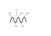
- the fiber 113 which comprises the fiber assembly 112 has a preferable crimped fiber shown in FIG. 11 and FIG.
- the crimped fiber 113 is formed with a large number of bent portions 113 ⁇ / b> A by being subjected to a predetermined winding and shrinking process. Accordingly, the fibers 113 are easily entangled by the bent portion 113A.
- the structure when the bent portion 113 ⁇ / b> A of one fiber 113 and the bent portion 113 ⁇ / b> A of the other fiber 113 are in contact with each other, the fiber assembly 112 is bulky. Therefore, when crimped fibers are used, the structure further facilitates the incorporation of dust into the crimped portions. This structure can be realized in particular by using crimped fibers formed from tow fibers.
- the fiber structure 111 can also be formed of a nonwoven fabric 114 as described later.
- the brush portion 110 is an example of the “brush portion” according to the present invention.
- This fiber component 111 is an example of the “fiber component” according to the present invention.
- the fiber 113 is an example of the “fiber” according to the present invention.
- This fiber assembly 112 is an example of the “fiber assembly” according to the present invention.
- This nonwoven fabric 114 is an example embodiment that corresponds to the “nonwoven fabric forming the fiber structure” according to the present invention.
- the brush portion 110 has a first brush region 110A in which the curing portion 140 is formed, and a second brush region 110B in which the curing portion 140 is not formed.
- the cleaning sheet 100 is laminated in the order of the base 120, the first brush region 110A, and the second brush region 110B.
- the cleaning body 110 can also be configured to include only the base 120 and the first brush region 110A without having the second brush region 110B.
- the fiber assembly 112 forming the first brush region 110A is a first fiber assembly 112A.
- the fiber assembly 112 that forms the second brush region 110B is a second fiber assembly 112B.
- the hardening part 140 is formed by welding the heat-welding fiber in the fiber structure 111. Further, the curing unit 140 may be formed by curing the impregnated body impregnated in the fiber structure 111.
- an impregnation body shows the raw material which can be apply
- a typical example of the impregnated body is an adhesive.
- the hardening part 140 in this invention hardens
- the curing unit 140 according to the present invention does not include the curing that occurs when connecting a plurality of components.
- the curing unit 140 is an example of the “curing unit” according to the present invention.
- the first brush region 110A is an example of the “first brush region” according to the present invention.
- the second brush region 110B is an example of the “second brush region” according to the present invention.
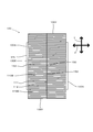
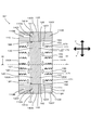
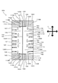
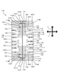
- FIG. 4 is a plan view of the cleaning sheet 100 viewed from the cleaning surface side
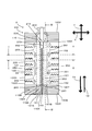
- FIG. 5 is a plan view of the cleaning sheet 100 viewed from the holding surface side.
- the base part 120 and the brush part 110 are joined by the joint part 150.
- the joining by the joining part 150 is preferably a welding joining.
- the joining part 150 can also be joined by an adhesive.
- the joint 150 extends along the longitudinal direction Y of the cleaning body 100.
- “along the longitudinal direction” typically means a state parallel to the longitudinal direction Y.
- the individual joints 150 are not necessarily parallel to the longitudinal direction Y, but the individual joints 150 as a whole are continuous in the longitudinal direction Y. Also satisfies “in the longitudinal direction” according to the present invention.
- the joint 150 extends along the longitudinal direction Y passing through the center of the longitudinal cross direction 100X of the cleaning body 100, and joins the base 120 and the first brush region 110A (first fiber assembly 112A). Part 151. Further, the joint 150 extends along the longitudinal direction Y in a state of being spaced from the first joint 151 in the longitudinal cross direction 100X, and the base 120 and the first brush region 110A (first fiber assembly 112A). And a second joint portion 152 that joins the two. A plurality of the second bonding portions 152 are formed in a state of being spaced along the longitudinal direction Y.
- the joint extends along the longitudinal direction Y passing through the center of the longitudinal cross direction 100X of the cleaning body 100, and the first brush region 110A (first fiber assembly 112A) and the second brush region 110B (second It has the 3rd junction part 153 which joins the fiber assembly 112B).
- the curing unit 140 is provided along the longitudinal direction of the first brush region 110A.
- the first joint portion 151 joins the base portion 120 and the cured portion 140 in the first brush region 110A.
- the 2nd junction part 152 joins the base 120 and the area
- the hardened portion 140 is formed by welding or impregnating the first brush region 110A as described above. Therefore, for example, when heat welding is performed as the first joint portion 151, the base portion 120 and the cured portion 140 may not necessarily be reliably connected or the joint state may be weakened.
- the second joint portion 152 joins the base portion 120 and the region where the hardened portion 140 is not formed in the first brush region 110A, the base portion 120 and the first brush region 110A can be reliably joined. it can.
- the hardening part 140 is formed ranging from one end part 100Y in the longitudinal direction Y to the other end part 100Y.
- a holding space 130 is formed between the base 120 and the first brush region 110 ⁇ / b> A between the pair of second joints 152 extending along the longitudinal direction Y.
- the holding space 130 is formed between the predetermined region extending along the longitudinal direction Y in the base portion 120 and the curing portion 140 in the first brush region 110A.
- the holding space 130 is an example of the “insertion portion” according to the present invention.
- the cleaning body holding part 220 in the holder 200 is inserted into the holding space 130.
- the hardening part 140 in the holding space 130 forms a low friction part 131 with respect to the cleaning body holding part 220.
- the region of the base 120 in the holding space 130 forms a high friction part 132 with respect to the cleaning body holding part 220.
- the definitions of “low friction” and “high friction” mean that the low friction part 131 has a lower friction coefficient than the high friction part 132.
- the low friction part 131 is an example of the “low friction part” according to the present invention.
- the length of the base portion 120 in the longitudinal direction Y is shorter than the length of the brush portion 110 in the longitudinal direction Y. Therefore, the brush portion 110 has a region where the base portion 120 is not disposed.
- a region of the brush portion 110 where the base portion 120 is not disposed has a high-rigidity portion 141 and a low-rigidity portion 142.
- the high-rigidity portion 141 is a region where the hardened portion 140 is formed
- the low-rigidity region 142 is a region where the hardened portion 140 is not formed.
- the hardened portion 140 formed in the region extending from the end of the brush portion 110 to the end of the base portion 120 forms the high-rigidity portion 141.
- the definitions of “high rigidity” and “low rigidity” mean that the high rigidity area 141 has higher rigidity than the low rigidity area 142.
- This highly rigid portion 141 is an example of the “highly rigid portion” according to the present invention.
- a region including the end portion 140Y on the longitudinal direction Y of the cured portion 140 is a high-rigidity end region 141A.
- the region that comes into contact with the object to be cleaned forms a scraped portion 141B.
- the scraping portion 141B includes a high-rigidity portion 141 (an end portion in the longitudinal direction Y of the curing portion 140 and a corner portion 141B1 where the high-rigidity portion 141 and the low-rigidity portion 142 intersect.
- the corner portion 141B1 is the cleaning body 100.
- This high-rigidity end region 141A is an example of the “high-rigidity end region” according to the present invention.
- This scraping portion 141B is an example of the “scraping portion” according to the present invention.
- a plurality of strip portions 170 are formed by a plurality of cut portions 171 provided from the end portions 120 ⁇ / b> X in the longitudinal cross direction X.
- the cut portion 171 has a zigzag shape.
- the shape of the cut portion 171 various shapes can be selected, and for example, it can be a straight shape.
- each holding member 221 can be inserted into the holding space 130.
- the cleaning body 100 is held by the cleaning body holder 200 by the holding member 221 being inserted into the holding space 130 along the insertion direction Y1.
- the cleaning body holder 200 is pulled out from the holding space 130 along the pulling direction Y2.
- the convex portion 260 is disposed between the adjacent second joint portions 152. Thereby, the engagement state of the cleaning body holder 200 and the cleaning body 100 is reliably maintained.
- the presser plate 270 holds the base 120 together with the holding member 221.
- FIG. 7 is an explanatory diagram showing the relationship between the components of the cleaning body 100 and the holder 200.
- the cleaning body 100 forms a distance D100 defined by a straight line having the shortest length in a straight line connecting both end portions 100Y in the longitudinal direction Y.
- the distance D100 is formed on the cleaning body 100, it can be said that the distance D100 is formed on the brush portion 110.
- the base 120 has a distance D200 defined by a straight line having the shortest length in a straight line connecting both end portions 120Y in the longitudinal direction Y. In the longitudinal direction Y, the base portion 120 is formed shorter than the brush portion 110.
- the base 120 is arranged in the central region of the brush portion 110 in the longitudinal direction Y.
- a distance D300 is formed in a region where the base portion 120 is not formed.
- the distance D300 is formed on one end 100Y side in the longitudinal direction Y of the cleaning body 100 and on the other end 100Y side, respectively.
- the distance 300D is a straight line having the shortest length in a straight line connecting the end portion 120Y in the longitudinal direction Y of the base portion 120 and the end portion 100Y in the longitudinal direction Y of the cleaning body 100 (brush portion 110). It can also be defined as follows.
- the holder 200 forms a distance D400 defined by a straight line having the shortest length in a straight line connecting the root portion of the holding member 221 and the distal end portion 240 in the longitudinal direction Y.
- the length of the distance D400 is shorter than the total length of the distance D200 and one distance D300. That is, an area where the holding member 221 is not disposed is formed in an area on the distal end portion 240 side of the holding member 221 in the cleaning body 100.
- the distance D400 is formed slightly longer than the distance D200.
- the region where the holding member 221 is not arranged in the cleaning body 100 is a straight line having the shortest length in a straight line connecting the distal end portion 240 of the holding member 221 and the end portion 100Y in the longitudinal direction Y of the cleaning body 100.
- a distance D500 defined by is formed. The length of the distance D500 is shorter than the length of the distance D300.
- the cleaning body 100 is not supported by the holding member 221.
- a highly rigid region 141A is formed. Therefore, even when the user uses the cleaning tool A, the region where the distance D500 exists does not droop greatly.
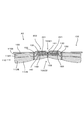
- FIG. 8 is a diagram showing a cross section taken along line II in FIG. 6, and FIG. 9 is a diagram showing a cross section taken along line II-II in FIG.
- the second brush region 110 ⁇ / b> B (second fiber assembly 112 ⁇ / b> B) has a cured portion facing region 160 that faces the cured portion 140. Since the hardening part opposing area
- region 160 has opposed the hardening part 140, it becomes a structure which is hard to get entangled with the fiber 113 of 112 A of 1st fiber aggregates. That is, the first fiber assembly 112A and the second fiber assembly 112B are configured to be less likely to be entangled.
- the dust captured by the cleaning body 100 is easily moved toward the back of the fiber assembly 112 (in the direction of the first fiber assembly 112A as viewed from the second fiber assembly 112B) by the cleaning operation by the user. . Therefore, more dust can be captured.
- the cleaning tool A The operation of the cleaning tool A according to the embodiment of the present invention will be described with reference to FIG.
- the user holds the handle 211 of the handle part 210 and inserts the holding member 221 into the insertion space 130 of the cleaning body 100.
- the distal end portion 240 of the holding member 221 is brought into contact with the curing portion 140 in the insertion space 130.
- the hardening part 140 of the insertion space 130 forms a low friction part 131. That is, the user can insert the distal end portion 240 of the holding member 221 while abutting against the low friction 131. Therefore, the mounting work of the holder 200 and the cleaning body 100 is facilitated.
- the user holds the handle 211 of the handle unit 210 and brings the cleaning body 100 into contact with the object to be cleaned.
- the brush unit 110 can collect or remove dust to be cleaned in the brush unit 110.
- the first fiber aggregate 112A and the second fiber aggregate 112B in the brush portion 110 are not easily entangled by the cured portion 140 and the cured portion facing region 160. Therefore, the cleaning body 100 can capture dust efficiently.
- the other surface 100Z2 of the cleaning body 100 is pressed against the object to be cleaned.
- the first surface 220Z1 of the cleaning body holding part 220 is pressed against the high friction part 132. Therefore, detachment between the holder 200 and the cleaning body 100 during cleaning can be prevented.
- the hardening part 140 in the front end direction (direction facing the handle part 210) of the cleaning tool A forms a high-rigidity part 141. Therefore, it can prevent that the front-end
- the hardening part 140 in the front end direction of the cleaning tool A has a scraping part 141B.
- the scraping portion 141B has a corner portion 141B1. Therefore, the user can scrape dust by bringing the scraping portion 141B and the corner portion 141B1 into contact with the object to be cleaned.
- the holder 200 is pulled out of the cleaning body 100. Also at this time, the user can pull out the front end portion 240 of the holding member 221 while contacting the low friction 131. Therefore, the work of detaching the holder 200 and the cleaning body 100 is facilitated.
- FIG. 11 shows the fibers 113 that form the fiber assembly 112.
- the fiber 113 which concerns on FIG. 11 shows the stationary state in which the external force is not applied. Since the fiber 113 is a crimped fiber, it has a plurality of bent portions 113A and has a zigzag shape. The bent portion 113A is also called a crimp portion. The fiber 113 can be expanded and contracted by having the bent portion 113A.
- FIG. 12 shows a state in which an external force (tension) is applied in opposite directions to both ends of the fiber 113 in a stationary state.
- the fibers 113 can be extended by separating the distance between the bent portions 113A.
- the fiber 113 returns from the extended state shown in FIG. 12 to the stationary state shown in FIG.
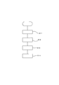
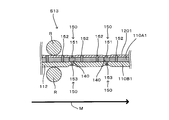
- FIG. 13 is a flowchart showing the first manufacturing process.
- the first step S11 is a step of forming the cured portion 140 in the first brush region 110A
- the base 120 is laminated on the first brush region 110A
- the first brush region 110A and the base 120 are joined to each other.
- 151 and the second step S12 which is a step of connecting by the joint portion 152
- the second brush region 110B is stacked on the first brush region 110A
- the first brush region 110A and the second brush region 110B are joined by the joint portion 153.
- the third step S13 which is a step of connecting, the step of obtaining the cleaning body 100 by cutting the laminated base 120, the first brush region 110A, and the second brush region 110B at predetermined positions. 4 steps S14.
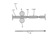
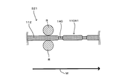
- FIG. 14 shows the first step S11.
- the first brush material 110A1 that becomes the first brush region 110A is supplied.
- the first brush material 110A1 is formed of the fiber assembly 112.
- a predetermined area of the first brush material 110A1 is heated. Accordingly, the cured portion 140 is formed by welding the fibers 113 constituting the fiber assembly 112.
- This 1st process S11 is an example of "a process of forming a hardening part in the brush part" concerning the present invention.
- each material is supported by the support roll R and is transferred in the machine direction M by a drive mechanism (not shown).
- the fiber orientation direction in the fiber assembly 112 approximately matches the machine direction M.
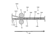
- FIG. 15 shows the second step S12.
- the base material 1201 forming the base 120 is supplied to the first brush material 110A1.
- the base material 1201 and the first brush material 110A1 are joined by the joint 150.
- the joint 150 is a pair of second joints that joins the first joint 151 that joins the base material 1201 and the curing part 140 and the predetermined region of the first brush material 110A1 that does not have the base material 121 and the cure part 140.
- a junction 152 is provided.
- the region where the joint 150 is formed is heated. As a result, the base material 1201 and the curing part 140, and the base material 1201 and the first brush material 110A1 are welded.
- a holding space 130 is formed between the base material 1201 and the first brush material 110A1 between the pair of second joints 152 that are separated in the machine direction M.
- the step of forming the second joint portion 152 with respect to the base material 1201 and the first brush material 110A1 includes the steps of “connecting the base to the brush portion, and between the brush portion and the base. And a step of forming an insertion portion for inserting the holding portion.
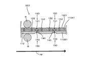
- FIG. 16 shows the third step S13.
- region 110B is supplied with respect to the surface where the base material 120 in 1st brush material 110A1 is not arrange
- the second brush material 110B1 is formed of the fiber assembly 112. Then, the second brush material 110 ⁇ / b> B ⁇ b> 1 and the curing portion 140 are joined by the third joint portion 153 as the joint portion 150.
- the third joint portion 153 is formed by heat welding by heating predetermined regions of the second brush material 110B1 and the curing portion 140.
- FIG. 17 shows the fourth step S14.
- the base material 1201, the first brush material 110A1, and the second brush material 110B1 that are stacked and welded are cut in a predetermined region.
- the cleaning body 100 of the cleaning tool A according to the present invention is manufactured.
- FIG. 18 is a flowchart showing the second manufacturing process.
- the first step S21 is a step of forming the cured portion 140 in the first brush region 110A
- the base 120 is laminated on the first brush region 110A
- the first brush region 110A and the base 120 are joined to each other.
- the second brush region 110B is stacked on the first brush region 110A, and the first brush region 110A and the second brush region 110B are joined to each other by the joint portion 151 and the joint portion 153.
- the third step S23 which is a step of connecting, the step of obtaining the cleaning body 100 by cutting the laminated base 120, the first brush region 110A, and the second brush region 110B at predetermined positions.
- 4 steps S24 is a step of connecting, the step of obtaining the cleaning body 100 by cutting the laminated base 120, the first brush region 110A, and the second brush region 110B at predetermined positions.
- FIG. 19 shows the first step S21. Since 1st process S21 is the same as 1st process S11 in a 1st manufacturing method, it abbreviate
- FIG. 20 shows the second step S22.
- the base material 1201 forming the base 120 is supplied to the first brush material 110A1.
- the base material 1201 and the first brush material 110A1 are joined by the joint 150. That is, as the joint portion 150, a pair of second joint portions 152 that join the base material 121 and a predetermined region of the first brush material 110A1 that does not have the curing portion 140 are provided.
- the region where the joint 150 is formed is heated. As a result, the base material 1201 and the first brush material 110A1 are welded.
- a holding space 130 is formed between the base material 1201 and the first brush material 110A1 between the pair of second joints 152 that are separated in the machine direction M.
- the step of forming the second joint portion 152 with respect to the base material 1201 and the first brush material 110A1 includes the steps of “connecting the base to the brush portion, and between the brush portion and the base. And a step of forming an insertion portion for inserting the holding portion.
- FIG. 21 shows the third step S23.
- region 110B is supplied with respect to the surface in which the base material 120 in 1st brush material 110A1 is not arrange
- the second brush material 110B1 is formed of the fiber assembly 112.
- the junction part 150 the 1st junction part 151 which joins the base material 1201 and the hardening part 140, and the 3rd junction part 153 which joins the 2nd brush material 110B1 and the hardening part 140 are provided.
- the first joint portion 151 and the third joint portion 153 are formed by heat welding by heating predetermined regions of the second brush material 110B1 and the curing portion 140.
- the 1st junction part 151 and the 3rd junction part 153 are provided by the single heat welding apparatus. Therefore, the first joint 151 and the third joint 153 can be formed at the same time, so that a stable production speed can be maintained.
- FIG. 22 shows the fourth step S24.
- the base material 1201, the first brush material 110A1, and the second brush material 110B1 that are stacked and welded are cut in a predetermined region.
- cleaning object 100 of cleaning tool A concerning the present invention is manufactured.
- FIGS. 14 to 17 and 19 to 22 described above the example in which the fiber assembly 112 is used as the fiber component 111 that forms the brush portion 110 has been described.
- a nonwoven fabric 114 can be used as the fiber structure 111.
- the example in which the hardened portion 140 is formed by heat welding has been described.
- the hardening part 140 can also be formed by hardening the impregnated body impregnated in the fiber structure 111.
- the cleaning tool A1 which concerns on a 1st modification differs in the structure of the cleaning body compared with the cleaning tool A in the above-mentioned embodiment. That is, the cleaning body 101 according to the first modification does not have the first joint portion 151 as the joint portion 150. For this reason, in the cleaning body 101 according to the above-described embodiment, the holding space 130 is divided into two regions by the first joint portion 151. However, in the cleaning body 101 according to the first modification, the holding space 130 is divided. Has a single region.
- the holding space 130 has a single region, in the mounting of the holding space 130 and the cleaning body holding part 220 of the holding tool 200, the same action as the cleaning tool A of the above embodiment is performed. And there is an effect.
- the holder 201 of the cleaning tool A1 according to the first modification has the same configuration as the holder 200 according to Embodiment A.
- the cleaning body holding portion 220 of the holder 201 can be configured as a single structure.
- the cleaning tool A2 which concerns on a 2nd modification differs in the structure of the cleaning body compared with the cleaning tool A in the above-mentioned embodiment. That is, in the cleaning body 102 according to the second modified example, the second joint 152 as the joint 150 welds all of the base 120, the first brush region 110A, and the third brush region 110B. That is, in the other surface 100Z2 of the cleaning body 102, a location where the second joint portion 152 exists and a location where it does not exist are formed.
- the second fiber assembly 112B has a fixed end joined to the third joint 153 and a free end at a location where the second joint 152 does not exist on the other surface 100Z2.
- the second fiber assembly 112B has a fixed end joined to the second joint 152 and a free end at a location where the second joint 152 exists on the other surface 100Z2. That is, in the cleaning tool A2 according to the second modified example, the second fiber assembly 112B includes a mixture of regions having fibers of different lengths. Therefore, it becomes possible to capture dust effectively between areas having fibers of different lengths.
- a third modification will be described based on FIG.
- the cleaning tool A3 which concerns on a 3rd modification differs in the structure of the cleaning body compared with the cleaning tool A in the above-mentioned embodiment.
- the holder 203 (not shown) according to the third modification has the same configuration as the holder 200 in the embodiment. That is, in the cleaning body 103 according to the third modification, the formation region of the hardened portion 140 in the longitudinal direction Y is within the range where the base portion 120 exists. Therefore, in the region where the hardened portion 140 is formed, the low friction portion 131, the high friction portion 132, and the hardened portion facing region 160 are formed in the same manner as the cleaning body 100 in the embodiment.
- the hardened portion facing region 160 is not particularly formed. That is, in a region where the hardened portion 140 is not formed, the first fiber aggregate 112A and the second fiber aggregate 112B are likely to be entangled. As a result, the region where the first fiber assembly 112A and the second fiber assembly 112B are entangled is different between the region where the cured portion 140 exists and the region where the cured portion 140 does not exist. Therefore, a step is likely to occur between the fiber assembly 112 in the region where the cured portion 140 exists and the fiber assembly 112 in the region where the cured portion 140 does not exist. As a result, it becomes a structure which is easy to catch a dust with the said level
- the counter area 160 is formed.
- the region where the base 120 does not exist is between the longitudinal end 100Y of the cleaning body 104 and the longitudinal end 120Y of the base 120 closest to the longitudinal end 100Y in the brush portion 110. You can also.
- the cured portion facing region 160 is not particularly formed.
- the first fiber aggregate 112A and the second fiber aggregate 112B are likely to be entangled.
- the region where the first fiber assembly 112A and the second fiber assembly 112B are entangled is different between the region where the cured portion 140 exists and the region where the cured portion 140 does not exist. Therefore, a step is likely to occur between the fiber assembly 112 in the region where the cured portion 140 exists and the fiber assembly 112 in the region where the cured portion 140 does not exist. As a result, it becomes a structure which is easy to catch a dust with the said level
- a fifth modification will be described based on FIG.
- the cleaning tool A5 which concerns on a 5th modification differs in the structure of the cleaning body compared with the cleaning tool A in the above-mentioned embodiment.
- a holder 205 (not shown) according to the fifth modification has the same configuration as the holder 200 in the embodiment. That is, in the cleaning body 105 according to the fifth modification, the region where the hardened portion 140 is formed in the longitudinal direction Y is a region including a boundary region 133 that is a boundary between the base 120 and the brush portion 110.
- the low friction portion 131, the high friction portion 132, the high rigidity portion 141, and the hardened portion facing region 160 are formed as in the cleaning body 100 in the embodiment. To do.
- the hardened portion facing region 160 is not particularly formed. That is, in a region where the hardened portion 140 is not formed, the first fiber aggregate 112A and the second fiber aggregate 112B are likely to be entangled. As a result, the region where the first fiber assembly 112A and the second fiber assembly 112B are entangled is different between the region where the cured portion 140 exists and the region where the cured portion 140 does not exist.
- the cleaning tool A6 according to the sixth modification is different from the cleaning tool A in the above-described embodiment in the configuration of the cleaning body. That is, the cleaning body 106 according to the sixth modification is a brush portion.
- a fiber structure 111 forming 110 is formed by a nonwoven fabric 114. That is, the first brush region 110A is formed of the first nonwoven fabric 114A, and the second brush region 110B is formed of the second nonwoven fabric 114B.
- one first nonwoven fabric 114 and two second nonwoven fabrics 114B are formed by two nonwoven fabrics 114, but the number thereof is arbitrary.
- the nonwoven fabric 114 can use the nonwoven fabric of the structure similar to the base 120.
- a nonwoven fabric different from the base 120 can be used as the nonwoven fabric 114.
- the same nonwoven fabric 114 can be used for the first nonwoven fabric 114A and the second nonwoven fabric 114B.
- the nonwoven fabric 114 different from the 1st nonwoven fabric 114A and the 2nd nonwoven fabric 114B can be used.
- the base 120 and the nonwoven fabric 114 are formed with a cut portion 171 and a strip portion 170. Also in the cleaning body 106, the curing portion 140 is formed.
- the cleaning body 106 is similar to the cleaning body 100 in the embodiment in that the low friction part 131, the high friction part 132, the high rigidity part 141, the high rigidity end part region 141A, the scraping part 141B, and the corner part. 141B and the hardened
- region 160 are formed. Therefore, also in the cleaning body 106 which concerns on a 6th modification, there exists an effect
- a seventh modification will be described with reference to FIG. Note that the cleaning tool A7 according to the seventh modification is different from the cleaning tool A in the above-described embodiment in the configuration of the holder. That is, the holder 207 according to the seventh modification is a cleaning body.
- a resistance portion 280 is provided on the first surface 220Z1 of the holding portion 220.
- the resistance portion 280 has a configuration for increasing the resistance with the high friction portion 132. Specifically, it is constituted by a convex portion protruding from the first surface 220Z1. Further, the convex portion has a top portion with a sharp tip. Further, the top is directed toward the handle portion 210.
- the cleaning tool A8 according to the eighth modification is different from the cleaning tool A in the above-described embodiment in the configuration of the cleaning body. That is, the cleaning body 108 according to the eighth modification is a cleaning body.
- a third fiber assembly 112C is provided as a third brush region 110C on the one surface 100Z1 side in 108.
- the third fiber assembly 112 ⁇ / b> C is joined to the base portion 120 by the fourth joint portion 154.
- the cleaning body 108 according to the eighth modification exhibits the functions and effects exhibited by the cleaning body 100 according to the embodiment. Furthermore, it is possible to perform cleaning not only on the other surface 100Z2 side of the cleaning body 108 but also on the one surface 100Z1 side.
- the cleaning tool according to the present invention is not limited to the configurations described in the above-described embodiment and the first to eighth modifications. That is, the configurations described in the embodiment and the first to eighth modifications can be combined as appropriate. Furthermore, it is possible to make a modified example of another configuration.
- the cleaning tools A, A1, A2, A3, A4, A5, A6, A7, and A8 are examples of the “cleaning tool” according to the present invention.
- the cleaning bodies 100, 101, 102, 103, 104, 105, 106, 107, and 108 are examples of the “cleaning sheet” according to the present invention.
- the cleaning body holders 200, 201, 202, 203, 204, 205, 206, 207 and 208 are examples of the “holding tool” according to the present invention.
- the longitudinal direction Y is an example of the “longitudinal direction” according to the present invention.
- the longitudinal cross direction X is an example of the “longitudinal cross direction” according to the present invention.
- the cleaning body holding unit 220 is an example embodiment that corresponds to the “holding unit” according to the present invention.
- the handle part 210 is an example embodiment that corresponds to the “gripping part” according to the present invention.
- the base 120 is an example of the “base” according to the present invention.
- the brush portion 110 is an example of a “brush portion” according to the present invention.
- the fiber structure 111 is an example embodiment that corresponds to the “fiber structure” according to the present invention.
- the fiber 113 is an example of the “fiber” according to the present invention.
- the fiber assembly 112 is an example of the “fiber assembly” according to the present invention.
- the nonwoven fabric 114 is an example embodiment that corresponds to the “nonwoven fabric forming the fiber structure” according to the present invention.
- the holding space 130 is an example of the “insertion portion” according to the present invention.
- the curing unit 140 is an example of the “curing unit” according to the present invention.
- the first brush region 110A is an example of the “first brush region” according to the present invention.
- the second brush region 110B is an example of the “second brush region” according to the present invention.
- the holding space 130 is an example of the “insertion portion” according to the present invention.
- the low friction part 131 is an example of the “low friction part” according to the present invention.
- the high rigidity portion 141 is an example of the “high rigidity portion” according to the present invention.
- the high-rigidity end region 141A is an example of the “high-rigidity end region” according to the present invention.
- the scraping portion 141B is an example of the “scraping portion” according to the present invention.
- 1st process S11 is an example of the "process which forms a hardening part in the said brush part" based on this invention.
- the step of forming the second joint portion 152 with respect to the base material 1201 and the first brush material 110A1 is an example of the “step of connecting the base to the brush portion” according to the present invention.
- the step of forming the second joint portion 152 with respect to the base material 1201 and the first brush material 110A1 is related to the present invention “the step of connecting the base to the brush portion, and between the brush portion and the base. And a step of forming an insertion portion for inserting the holding portion.
- the cleaning tool according to the present invention can be configured as follows.
- (Aspect 1) In a cleaning tool having a cleaning sheet and a holder for holding the cleaning sheet,
- the cleaning sheet is configured to extend in both a longitudinal direction defined by a direction in which the holder is inserted into the cleaning sheet and a longitudinal intersecting direction defined by a direction intersecting the longitudinal direction.
- the holder has a holding part for holding the cleaning sheet, and a holding part that is connected to the holding part and is held by a user.
- the cleaning sheet includes a brush portion configured to be able to clean an object to be cleaned, a base portion formed by a nonwoven fabric to which the brush portion is connected and whose length in the longitudinal direction is shorter than the brush portion, and the brush portion. And an insertion part that is formed between the base part and the holding part is inserted,
- a cleaning tool, wherein a hardened portion is formed in the longitudinal region of the brush portion forming the insertion portion.
- a cleaning tool according to aspect 1 The cleaning tool, wherein the brush portion is formed of a fiber structure.
- a cleaning tool according to aspect 2 The said fiber structure is formed with the fiber assembly by the some fiber which has orientation in a predetermined direction, The cleaning tool characterized by the above-mentioned.
- a cleaning tool according to aspect 2 The said fiber structure is formed with a nonwoven fabric, The cleaning tool characterized by the above-mentioned.
- a cleaning tool according to any one of aspects 1 to 4 The said hardening part is formed when the impregnation body impregnated in the said fiber structure hardens
- a cleaning tool according to aspect 7 The high-rigidity end region, which is a region including the end portion in the longitudinal direction of the high-rigidity portion, forms a scraped portion that comes into contact with the object to be cleaned.
- a cleaning tool according to aspect 9 In the longitudinal direction, a region of the base portion facing the hardened portion forms a high friction portion having a higher friction coefficient than the low friction portion.
- a cleaning tool according to any one of aspects 1 to 10 The said brush part has the 1st brush area
- the cleaning tool characterized by the above-mentioned.
- the brush part is provided on one side and the other side of the base part.
- a cleaning tool according to aspect 14 The joint portion has a first joint portion that extends along the longitudinal direction passing through the center of the cleaning body in the longitudinal crossing direction and joins the base portion and the first brush region. Cleaning tool.
- a cleaning tool according to aspect 14 or 15 The said joint part has a pair of 2nd junction part which joins the said base and the said 1st brush area
- the cleaning tool characterized by the above-mentioned.
- a cleaning tool according to aspect 16 The said insertion part is formed between the said base part and the said brush part between a pair of said 2nd junction parts extended along the said longitudinal direction, The cleaning tool characterized by the above-mentioned.
- a cleaning tool according to any one of aspects 14 to 18, comprising:
- the joining portion includes a third joining portion that extends along the longitudinal direction passing through the center in the longitudinal crossing direction of the cleaning body and joins the first brush region and the second brush region. Characteristic cleaning tool.
- the holding portion has a first surface directed toward the base in a state where the cleaning sheet and the holding tool are mounted, and a second surface facing the first surface,
- the cleaning sheet has a base part and a brush part joined to the base part, Forming a cured portion in the brush portion; Connecting the base to the brush portion; Forming an insertion part for inserting the holding part between the brush part and the base part;
- the manufacturing method of the cleaning tool characterized by having.
Landscapes
- Cleaning Implements For Floors, Carpets, Furniture, Walls, And The Like (AREA)
Abstract
【課題】 清掃用具に関する一層合理的な構築技術を提供する。 【解決手段】清掃用具(A)は清掃シート(100)と保持具(200)とを有し、清掃シート(100)は、刷毛部(110)と、長手方向(Y)における長さが刷毛部(110)よりも短い不織布により形成された基部(120)と、刷毛部(110)と基部(120)の間に形成されるとともに保持部(220)が挿入される挿入部(130)とを有し、挿入部(130)を形成する刷毛部(110)における長手方向(Y)の領域には、硬化部(140)が形成される。
Description
本発明は、清掃対象を清掃するための清掃用具に関する。
特開2007-159612号公報には、把手に取り付けられて使用される清掃用物品が開示されている。清掃用物品は、繊維層と、把手挿入部とを有している。把手挿入部は、繊維層に設けられた融着部分により形成されている。すなわち、一対の繊維層の所定領域を融着させることにより融着部分を形成するとともに、この一対の繊維層における融着部分同士を対向させることにより、把手挿入部が形成される。
一方、特開2007-159612号に記載された清掃用物品は、把手挿入部が一対の繊維層に形成された融着部分同士を対向させて形成されていたため、設計自由度が低かった。
一方、特開2007-159612号に記載された清掃用物品は、把手挿入部が一対の繊維層に形成された融着部分同士を対向させて形成されていたため、設計自由度が低かった。
本発明は、このような点に鑑みて創案されたものであり、清掃用具に関する一層合理的な構築技術を提供することを目的とする。
上記課題を解決するため、本発明における清掃用具は、清掃シートと、清掃シートを保持する保持具とを有する。
清掃シートは、清掃シートに保持具を挿入する方向によって規定される長手方向と、長手方向と交差する方向によって規定される長手交差方向の双方に延在するように構成されている。
保持具は、清掃シートを保持するための保持部と、保持部に連結されてユーザに把持される把持部とを有する。
さらに、清掃シートは、清掃対象を清掃可能に構成された刷毛部と、刷毛部が接続されるとともに長手方向における長さが刷毛部よりも短い不織布により形成された基部と、刷毛部と基部の間に形成されるとともに保持部が挿入される挿入部とを有する。
挿入部を形成する刷毛部における長手方向の領域には、硬化部が形成される。
清掃シートは、清掃シートに保持具を挿入する方向によって規定される長手方向と、長手方向と交差する方向によって規定される長手交差方向の双方に延在するように構成されている。
保持具は、清掃シートを保持するための保持部と、保持部に連結されてユーザに把持される把持部とを有する。
さらに、清掃シートは、清掃対象を清掃可能に構成された刷毛部と、刷毛部が接続されるとともに長手方向における長さが刷毛部よりも短い不織布により形成された基部と、刷毛部と基部の間に形成されるとともに保持部が挿入される挿入部とを有する。
挿入部を形成する刷毛部における長手方向の領域には、硬化部が形成される。
また本発明に係る清掃用具における解決手段の一態様として、刷毛部は繊維構成体により形成される。
この繊維構成体は、所定の方向に配向性を有する複数の繊維による、繊維集合体により形成することができる。また、繊維構成体は、不織布により形成することができる。
この繊維構成体は、所定の方向に配向性を有する複数の繊維による、繊維集合体により形成することができる。また、繊維構成体は、不織布により形成することができる。
また本発明に係る清掃用具における解決手段の一態様として、繊維構成体は熱溶着性を有する繊維により形成することができる。この際、硬化部は、繊維構成体における熱溶着性繊維を溶着することにより形成することができる。
また本発明に係る清掃用具における解決手段の一態様として、硬化部は、繊維構成体に含浸された含浸体が硬化することにより形成されることもできる。
また本発明に係る清掃用具における解決手段の一態様として、長手方向において、刷毛部の端部と基部の端部に亘る領域内に形成された硬化部は、刷毛部における硬化部が形成されていない領域に比して高い剛性を有する高剛性部を形成することができる。
この場合、高剛性部は、保持部に保持されていない刷毛部領域の垂れ下がりを防止することができる。
この場合、高剛性部は、保持部に保持されていない刷毛部領域の垂れ下がりを防止することができる。
また本発明に係る清掃用具における解決手段の一態様として、高剛性部における前記長手方向上の端部を含む領域である高剛性端部領域は、清掃対象に当接される掻き出し部を形成することができる。この掻き出し部によって、ユーザは、清掃対象の汚れ、塵芥等を掻き出すことが可能となる。
また本発明に係る清掃用具における解決手段の一態様として、長手方向において、基部の両端部間に亘る領域内に形成された硬化部は、基部に比して低い摩擦係数を有する低摩擦部を形成することができる。この低摩擦部により、挿入空間に対する保持部の挿入がスムーズとなる。
また本発明に係る清掃用具における解決手段の一態様として、刷毛部は、硬化部が形成された第1刷毛領域と、硬化部が形成されていない第2刷毛領域とを有することができる。
特に、刷毛部が繊維集合体により形成されている場合には、第1刷毛領域と、第2刷毛領域とにおけるそれぞれの繊維集合体の絡みつきを低減させることができる。
特に、刷毛部が繊維集合体により形成されている場合には、第1刷毛領域と、第2刷毛領域とにおけるそれぞれの繊維集合体の絡みつきを低減させることができる。
また本発明に係る清掃用具における解決手段の一態様として、刷毛部は、基部の一方の面に設けることができる。
また本発明に係る清掃用具における解決手段の一態様として、刷毛部は、基部の一方の面および他方の面に設けることができる。
また、上記課題を解決するため、本発明における清掃用具の製造方法は、清掃シートと、清掃シートを保持する保持具とを有する清掃用具の製造方法に関する。
清掃シートは、基部と、基部に接合された刷毛部を有する構成であり、刷毛部に硬化部を形成する工程と、刷毛部に基部を接続する工程と、刷毛部と基部の間に、保持部を挿入するための挿入部を形成する工程とを有する。
清掃シートは、基部と、基部に接合された刷毛部を有する構成であり、刷毛部に硬化部を形成する工程と、刷毛部に基部を接続する工程と、刷毛部と基部の間に、保持部を挿入するための挿入部を形成する工程とを有する。
また本発明に係る清掃用具の製造方法における解決手段の一態様として、刷毛部は繊維構成体により形成することができる。繊維構成体は、特定の方向に配向性を有する複数の繊維による繊維集合体により形成することができる。また、繊維構成体は、不織布により形成することができる。
また本発明に係る清掃用具の製造方法における解決手段の一態様として、繊維構成体は熱溶着性を有する繊維により形成することができる。この際、硬化部は、繊維構成体における熱溶着性繊維を溶着することにより形成することができる。
また本発明に係る清掃用具の製造方法における解決手段の一態様として、硬化部は、繊維構成体に含浸された含浸体が硬化することにより形成することができる。
本発明によれば、清掃用具に関する一層合理的な構築技術を提供することが可能となる。
(清掃用具の概略)
以下、本発明の実施形態について、図1~図22を参照しつつ詳細に説明する。まず、本発明における「清掃用具」の一実施の形態である清掃用具Aの構成につき説明する。この清掃用具Aを用いて清掃される清掃対象としては、一戸建て、マンション、ビル、工場、車両などの室内、室外、屋外における被清掃面(床面、壁面、窓、天井面、外壁面、家具面、衣類、カーテン、寝具、照明、家電品など)や、人体の各構成部位における被清掃面などが挙げられる。これら各種の被清掃面は、平面として構成されてもよいし、或いは曲面、凹凸面、段差面として構成されてもよい。
以下、本発明の実施形態について、図1~図22を参照しつつ詳細に説明する。まず、本発明における「清掃用具」の一実施の形態である清掃用具Aの構成につき説明する。この清掃用具Aを用いて清掃される清掃対象としては、一戸建て、マンション、ビル、工場、車両などの室内、室外、屋外における被清掃面(床面、壁面、窓、天井面、外壁面、家具面、衣類、カーテン、寝具、照明、家電品など)や、人体の各構成部位における被清掃面などが挙げられる。これら各種の被清掃面は、平面として構成されてもよいし、或いは曲面、凹凸面、段差面として構成されてもよい。
図1に示すように、清掃用具Aは、清掃体ホルダ200と清掃体100で構成されている。清掃体ホルダ200は、清掃体100に着脱可能であり、清掃体100を保持するように構成されている。この清掃用具Aが本発明における「清掃用具」の一例である。この清掃体ホルダ200が、本発明における「保持具」の一例である。この、清掃体100が、本発明における「清掃シート」の一例である。
清掃体100は、長手方向Yと、長手方向Yと交差する方向によって規定される長手交差方向Xの双方に延在するように構成される。この長手方向Yは、清掃体100に清掃体ホルダ200を挿入する方向と平行な方向により規定される。この清掃体100に清掃体ホルダ200を挿入する方向は、挿入方向Y1とされる。この挿入方向Y1と反対向きの方向は引抜方向Y2とされる。
長手方向Yおよび長手交差方向Xのそれぞれと交差する方向は、厚み方向Zとされる。なお、本発明に係る実施形態の説明において、特別の記載がない限りは、「交差」とは「直交」を意味するものである。
この長手方向Yが、本発明における「長手方向」の一例である。この、長手交差方向Xが、本発明における「長手交差方向」の一例である。
長手方向Yおよび長手交差方向Xのそれぞれと交差する方向は、厚み方向Zとされる。なお、本発明に係る実施形態の説明において、特別の記載がない限りは、「交差」とは「直交」を意味するものである。
この長手方向Yが、本発明における「長手方向」の一例である。この、長手交差方向Xが、本発明における「長手交差方向」の一例である。
清掃体100は、さらに、長手方向Yと、長手交差方向Xの双方と交差する方向によって規定される方向である厚み方向Zにも延在される。清掃体100は、一方の面100Z1と、一方の面100Z1と対向する他方の面100Z2とを有する。他方の面100Z2は、清掃対象側に向けられる。
(清掃体ホルダの構成)
図2に示すように、清掃体ホルダ200は、ハンドル部210および清掃体保持部220を主体として構成されている。ハンドル部210は、長尺状に形成されており、清掃時にユーザに保持される部材である。ハンドル部210は、ハンドル211とハンドル接合部212を有している。ハンドル接合部212は、清掃体保持部220の連接部230に接合されている。そして、ハンドル211は、ハンドル接合部212から延在する長尺状に形成されている。このハンドル部210が、本発明における「把持部」の一例である。この清掃体保持部220が、本発明における「保持部」の一例である。
図2に示すように、清掃体ホルダ200は、ハンドル部210および清掃体保持部220を主体として構成されている。ハンドル部210は、長尺状に形成されており、清掃時にユーザに保持される部材である。ハンドル部210は、ハンドル211とハンドル接合部212を有している。ハンドル接合部212は、清掃体保持部220の連接部230に接合されている。そして、ハンドル211は、ハンドル接合部212から延在する長尺状に形成されている。このハンドル部210が、本発明における「把持部」の一例である。この清掃体保持部220が、本発明における「保持部」の一例である。
清掃体保持部220は、樹脂材料にて成型されており、清掃体100を保持するための部材である。清掃体保持部220は、長尺状に形成された2つの保持部材221、凸部260および押え板270等を主体として構成されている。具体的には、清掃体保持部220は、ポリプロピレン(PP)が使用されている。なお、清掃体保持部220は可撓性を有する樹脂材料を適宜選択することができる。例えば、ポリエチレン(PE)、ポリエチレンテレフタラート(PET)、アクリロニトリル-ブタジエン-スチレン樹脂(ABS)、ポリエステル系の熱可塑性エラストマーを使用できる。
清掃体保持部220は、第1面220Z1と、第1面220Z1と対向する第2面220Z2とを有する。第2面220Z2は、清掃作業時に清掃対象に向けられる面となる。
清掃体保持部220は、第1面220Z1と、第1面220Z1と対向する第2面220Z2とを有する。第2面220Z2は、清掃作業時に清掃対象に向けられる面となる。
保持部材221は、連接部230からハンドル211が延在する方向と反対の方向に向かって延在して形成されている。すなわち、保持部材221は、連接部230と、先端部240と、連接部230から先端部240に向かって延在した中間部250とを有する。2つの保持部材221の先端部240はそれぞれ自由端となっている。
凸部260は、中間部250における外側方向に設けられる。凸部260は、連接部230側に設けられた第1の凸部261と、先端部240側に設けられた第2の凸部262とからなる。
押え板270は、連接部230から突出して形成されている。押え板270は、一対の保持部材221の間に、保持部材221と平行に延在するように形成されている。押え板270は、下方に向けて凸形状となるように湾曲して形成される板状部材として構成され、更に下面に係止突部(図示省略)を備えている。
(清掃体の構成)
次に図3~図10を参照しつつ、清掃体100について説明する。清掃体100は、清掃対象の塵芥などの汚れを捕集する、汚れ捕集機能を有するシート状の清掃体である。図4~図7に示すように、清掃体100は、平面視で長方形状に形成されている。
この清掃体100は、一回使用を目安とした使い捨てタイプのものや、清掃対象の被清掃面から除去したごみや埃を保持しつつ複数回の使用を目安として交換を行う使い捨てタイプのものであってもよいし、或いは洗濯などを行ったうえで繰り返し使用することが可能なタイプのものであってもよい。
次に図3~図10を参照しつつ、清掃体100について説明する。清掃体100は、清掃対象の塵芥などの汚れを捕集する、汚れ捕集機能を有するシート状の清掃体である。図4~図7に示すように、清掃体100は、平面視で長方形状に形成されている。
この清掃体100は、一回使用を目安とした使い捨てタイプのものや、清掃対象の被清掃面から除去したごみや埃を保持しつつ複数回の使用を目安として交換を行う使い捨てタイプのものであってもよいし、或いは洗濯などを行ったうえで繰り返し使用することが可能なタイプのものであってもよい。
図3は、本発明の実施形態に係る清掃体100の各構成要素を示す分解斜視図である。
清掃体100において、基部120は不織布により形成されている。基部120は、長手交差方向X上の端部120Xと、長手方向Y上の端部120Yと、一方の面120Cと、他方の面120Dとを有する。この基部120が、本発明における「基部」の一例である。
基部120の他方の面120Bには、刷毛部110が配置される。本実施の形態においては、基部120の一方の面120Aには、何も配置されていない。一方、後述するように基部120の一方の面120Aに刷毛部110を配置することができる。なお、基部120は、長手方向Yにおける長さが刷毛部110よりも短く形成されている。この基部120が、本発明に係る「基部」の一例である。
基部120は不織布により形成されている。基部120を構成する不織布は、いずれも典型的には熱溶融性繊維(熱可塑性繊維)からなるシート状の不織布が使用されている。すなわち、これら基部120は、「不織布シート」とも称呼される。なお、清掃時の掃き出し機能を向上させるためには、剛性の高い不織布を用いるのが好ましい。
なお、この不織布は、ポリエチレン(PE)、ポリプロピレン(PP)、ポリエチレンテレフタレート(PET)などの合成繊維が使用される。また、不織布の形態としては、エアースルー法や、スパンボンド法により形成されたものが使用される。
一方、不織布以外であっても、布帛や、合成樹脂によるフィルム体などを使用することもできる。
なお、この不織布は、ポリエチレン(PE)、ポリプロピレン(PP)、ポリエチレンテレフタレート(PET)などの合成繊維が使用される。また、不織布の形態としては、エアースルー法や、スパンボンド法により形成されたものが使用される。
一方、不織布以外であっても、布帛や、合成樹脂によるフィルム体などを使用することもできる。
刷毛部110は、清掃対象を清掃可能とするために、繊維構成体111により形成される。この発明において、繊維構成体111とは、「繊維」により形成される構造物を示すものである。この発明において、「繊維」とは、典型的な単一の繊維によるものや、典型的な繊維が長さ方向および/または径方向にそろって形成されるもの(撚糸、紡績糸、複数の長繊維が部分的に接続された糸材など)を含むものである。ここで「典型的な繊維」とは、糸、織物などの構成単位であり、太さに比して十分な長さを持つ、細くてたわみやすい形態のものである。具体的には長い連続状の繊維が長繊維(フィラメント)とされ、短い繊維が短繊維(ステープル)とされる。
ここで、本実施形態に係る清掃体100において、繊維構成体111は、所定の方向に配向性を有する複数の繊維113による繊維集合体112により形成される。具体的には、繊維集合体112は長手交差方向Xに配向性を有する繊維113の集合体により形成される。
繊維集合体112は、長手交差方向Xに配向性を有するとともに厚み方向Zに積層された複数の繊維113により形成される。繊維113は柔軟な素材であるため、容易に屈曲、変形される。よって、繊維113の繊維配向方向とは、製品の設計上における繊維配向性のことを示すものである。
ここで、本実施形態に係る清掃体100において、繊維構成体111は、所定の方向に配向性を有する複数の繊維113による繊維集合体112により形成される。具体的には、繊維集合体112は長手交差方向Xに配向性を有する繊維113の集合体により形成される。
繊維集合体112は、長手交差方向Xに配向性を有するとともに厚み方向Zに積層された複数の繊維113により形成される。繊維113は柔軟な素材であるため、容易に屈曲、変形される。よって、繊維113の繊維配向方向とは、製品の設計上における繊維配向性のことを示すものである。
繊維集合体112は、典型的にはポリエチレン(PE)、ポリプロピレン(PP)、ポリエチレンテレフタレート(PET)、ナイロン、レーヨンなどを材質とし、実用上はトウを開繊することによって得られる長繊維(フィラメント)の集合体が用いられることが好ましい。特には、芯部分がポリプロピレン(PP)或いはポリエチレンテレフタレート(PET)であり、この芯部分の外面を覆う鞘部分がポリエチレン(PE)の複合繊維を用いて繊維集合体112が構成されるのが好ましい。また、この繊維集合体112を形成する繊維の繊度113は、1~50dtexのものが好ましく、更には2~10dtexのものが好ましい。
また、清掃時の汚れ捕集機能を向上させるために、繊維集合体112には、油剤が供給される。この油剤は、流動パラフィンを主成分とする。
また、清掃時の掃き出し機能を向上させるためには、剛性の高い繊維113、すなわち繊度が高い繊維113を含む繊維集合体112を用いるのが好ましい。また、繊維集合体112を構成する繊維113は、後述する図11および図12にて示される捲縮繊維が好ましい。捲縮繊維113は、所定の巻き縮み処理が付与されることにより多数の屈曲部113Aが形成される。よって、当該屈曲部113Aにより繊維113同士が絡みやすい構成とされる。また、一方の繊維113における屈曲部113Aと他方の繊維113における屈曲部113Aとが当接した場合には、繊維集合体112として嵩高な状態とされる。よって、捲縮繊維を用いると、更に捲縮部分にごみを取り込み易い構造とされる。本構造は、特にトウ繊維から形成された捲縮繊維を用いることによって実現され得る。
また、清掃時の掃き出し機能を向上させるためには、剛性の高い繊維113、すなわち繊度が高い繊維113を含む繊維集合体112を用いるのが好ましい。また、繊維集合体112を構成する繊維113は、後述する図11および図12にて示される捲縮繊維が好ましい。捲縮繊維113は、所定の巻き縮み処理が付与されることにより多数の屈曲部113Aが形成される。よって、当該屈曲部113Aにより繊維113同士が絡みやすい構成とされる。また、一方の繊維113における屈曲部113Aと他方の繊維113における屈曲部113Aとが当接した場合には、繊維集合体112として嵩高な状態とされる。よって、捲縮繊維を用いると、更に捲縮部分にごみを取り込み易い構造とされる。本構造は、特にトウ繊維から形成された捲縮繊維を用いることによって実現され得る。
一方、繊維構成体111は、後述するとおり不織布114により形成することもできる。この刷毛部110が、本発明に係る「刷毛部」の一例である。この繊維構成体111が、本発明に係る「繊維構成体」の一例である。この繊維113が、本発明に係る「繊維」の一例である。この繊維集合体112が、本発明に係る「繊維集合体」の一例である。この不織布114が、本発明に係る「繊維構成体を形成する不織布」の一例である。
刷毛部110は、硬化部140が形成された第1刷毛領域110Aと、硬化部140が形成されていない第2刷毛領域110Bとを有する。清掃シート100は、基部120、第1刷毛領域110A、第2刷毛領域110Bの順で積層される。なお、清掃体110は、第2刷毛領域110Bを有さずに、基部120と第1刷毛領域110Aのみからなる構成とすることもできる。
なお、第1刷毛領域110Aを形成する繊維集合体112は、第1繊維集合体112Aとされる。第2刷毛領域110Bを形成する繊維集合体112は、第2繊維集合体112Bとされる。
なお、第1刷毛領域110Aを形成する繊維集合体112は、第1繊維集合体112Aとされる。第2刷毛領域110Bを形成する繊維集合体112は、第2繊維集合体112Bとされる。
硬化部140は、繊維構成体111における熱溶着性繊維を溶着することにより形成される。また、硬化部140は、繊維構成体111に含浸された含浸体が硬化することにより形成されてもよい。なお、含浸体とは、製造工程において液状または半液状として塗布可能であり、その後硬化する素材を示す。含浸体の典型的な例としては、接着剤があげられる。
なお、本発明における硬化部140は、繊維構成体111のみを硬化するものである。すなわち、後述するように、刷毛部110と基部120とは接合部150により接続されるものである。この意味において、接合部150も「硬化」自体はされるものである。一方、本発明に係る硬化部140は、このように複数の構成要素を接続する際に生じる硬化を含まないものである。
この硬化部140が、本発明に係る「硬化部」の一例である。この第1刷毛領域110Aが、本発明に係る「第1刷毛領域」の一例である。この第2刷毛領域110Bが、本発明に係る「第2刷毛領域」の一例である。
なお、本発明における硬化部140は、繊維構成体111のみを硬化するものである。すなわち、後述するように、刷毛部110と基部120とは接合部150により接続されるものである。この意味において、接合部150も「硬化」自体はされるものである。一方、本発明に係る硬化部140は、このように複数の構成要素を接続する際に生じる硬化を含まないものである。
この硬化部140が、本発明に係る「硬化部」の一例である。この第1刷毛領域110Aが、本発明に係る「第1刷毛領域」の一例である。この第2刷毛領域110Bが、本発明に係る「第2刷毛領域」の一例である。
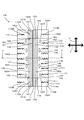
図4は清掃シート100を清掃面側から見た平面図、図5は清掃シート100を保持面側から見た平面図である。
基部120と刷毛部110とは、接合部150により接合される。この接合部150による接合は、溶着接合とすることが好ましい。一方、接合部150は、接着剤により接合することもできる。
接合部150は、清掃体100の長手方向Yに沿って延在する。ここで、「長手方向に沿う」とは、典型的には長手方向Yと平行ある状態を示す。一方、例えば複数の接合部150が存在する状態において、個々の接合部150は必ずしも長手方向Yとは平行ではないが、個々の接合部150全体として長手方向Yに連続している状態であっても、本発明に係る「長手方向に沿う」を満たすものである。
接合部150は、清掃体100の長手方向Yに沿って延在する。ここで、「長手方向に沿う」とは、典型的には長手方向Yと平行ある状態を示す。一方、例えば複数の接合部150が存在する状態において、個々の接合部150は必ずしも長手方向Yとは平行ではないが、個々の接合部150全体として長手方向Yに連続している状態であっても、本発明に係る「長手方向に沿う」を満たすものである。
接合部150は、清掃体100の長手交差方向100Xの中心を通過する長手方向Yに沿って延びるとともに、基部120と第1刷毛領域110A(第1繊維集合体112A)とを接合する第1接合部151を有する。
また、接合部150は、長手交差方向100Xにおいて第1接合部151とは間隔を空けた状態で長手方向Yに沿って延びるとともに、基部120と第1刷毛領域110A(第1繊維集合体112A)とを接合する第2接合部152を有する。第2接合部152は、長手方向Yに沿って間隔を空けた状態で複数個形成される。
また、接合部は、清掃体100の長手交差方向100Xの中心を通過する長手方向Yに沿って延びるとともに、第1刷毛領域110A(第1繊維集合体112A)と第2刷毛領域110B(第2繊維集合体112B)とを接合する第3接合部153を有する。
また、接合部150は、長手交差方向100Xにおいて第1接合部151とは間隔を空けた状態で長手方向Yに沿って延びるとともに、基部120と第1刷毛領域110A(第1繊維集合体112A)とを接合する第2接合部152を有する。第2接合部152は、長手方向Yに沿って間隔を空けた状態で複数個形成される。
また、接合部は、清掃体100の長手交差方向100Xの中心を通過する長手方向Yに沿って延びるとともに、第1刷毛領域110A(第1繊維集合体112A)と第2刷毛領域110B(第2繊維集合体112B)とを接合する第3接合部153を有する。
硬化部140は、第1刷毛領域110Aの長手方向に沿って設けられる。第1接合部151は、基部120と、第1刷毛領域110Aにおける硬化部140とを接合する。一方、第2接合部152は、基部120と、第1刷毛領域110Aにおける硬化部140が形成されていない領域とを接合する。
硬化部140は、前述のとおり第1刷毛領域110Aを溶着もしくは含浸体を含浸させることにより形成される。よって、例えば第1接合部151として熱溶着を行う場合は、基部120と硬化部140とが必ずしも確実に接続されない場合や、接合状態が弱くなる場合がある。一方、第2接合部152は、基部120と、第1刷毛領域110Aにおける硬化部140が形成されていない領域とを接合するため、基部120と第1刷毛領域110Aとを確実に接合することができる。
なお、硬化部140は、長手方向Yにおける一方の端部100Yから他方の端部100Yに亘り形成される。
硬化部140は、前述のとおり第1刷毛領域110Aを溶着もしくは含浸体を含浸させることにより形成される。よって、例えば第1接合部151として熱溶着を行う場合は、基部120と硬化部140とが必ずしも確実に接続されない場合や、接合状態が弱くなる場合がある。一方、第2接合部152は、基部120と、第1刷毛領域110Aにおける硬化部140が形成されていない領域とを接合するため、基部120と第1刷毛領域110Aとを確実に接合することができる。
なお、硬化部140は、長手方向Yにおける一方の端部100Yから他方の端部100Yに亘り形成される。
長手方向Yに沿って延びる一対の第2接合部152の間における、基部120と第1刷毛領域110Aとの間には、保持空間130が形成される。換言すると、保持空間130は、基部120における長手方向Yに沿って延びる所定領域と、第1刷毛領域110Aにおける硬化部140との間に形成されるものである。この保持空間130が、本発明に係る「挿入部」の一例である。
保持空間130には、保持具200における清掃体保持部220が挿入される。保持空間130における硬化部140は、清掃体保持部220に対する低摩擦部131を形成する。一方、保持空間130における基部120の領域は、清掃体保持部220に対する高摩擦部132を形成する。ここで、「低摩擦」と「高摩擦」の定義としては、低摩擦部131は高摩擦部132よりも摩擦係数が低いことを意味する。この低摩擦部131が本発明に係る「低摩擦部」の一例である。
保持空間130には、保持具200における清掃体保持部220が挿入される。保持空間130における硬化部140は、清掃体保持部220に対する低摩擦部131を形成する。一方、保持空間130における基部120の領域は、清掃体保持部220に対する高摩擦部132を形成する。ここで、「低摩擦」と「高摩擦」の定義としては、低摩擦部131は高摩擦部132よりも摩擦係数が低いことを意味する。この低摩擦部131が本発明に係る「低摩擦部」の一例である。
前述した通り、基部120の長手方向Yにおける長さは、刷毛部110の長手方向Yにおける長さよりも短い。よって、刷毛部110は、基部120が配置されていない領域を有する。この刷毛部110における基部120が配置されていない領域は、高剛性部141と低剛性部142とを有する。ここで、高剛性部141とは、硬化部140が形成されている領域であり、低剛性領域142とは、硬化部140が形成されていない領域である。換言すると、長手方向100Yにおいて、刷毛部110の端部と基部120の端部に亘る領域内に形成された硬化部140は、高剛性部141を形成するということができる。ここで、「高剛性」と「低剛性」の定義としては、高剛性領域141は低剛性領域142よりも剛性が高いことを意味する。この高剛性部141が、本発明に係る「高剛性部」の一例である。
高剛性部141において、硬化部140の長手方向Y上の端部140Yを含む領域は高剛性端部領域141Aとされる。この高剛性端部領域141Aにおいて、清掃対象に当接される領域は掻き出し部141Bを形成する。掻き出し部141Bは、高剛性部141(硬化部140における長手方向Y上の端部と、高剛性部141と低剛性部142とが交差する角部141B1を有する。角部141B1は、清掃体100の長手方向Yにおける端部100Yを通過する長手交差方向100Xの仮想線に対し、直角もしくは鋭角を構成する。この高剛性端部領域141Aが本発明に係る「高剛性端部領域」の一例である。この掻き出し部141Bが、本発明に係る「掻き出し部」の一例である。
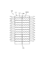
基部120には、長手交差方向X上の端部120Xから設けられた複数の切込み部171により、複数の短冊部170が形成される。なお、後述するが、刷毛部110を形成する繊維構成体111が不織布114である場合は、この不織布114に対しても切込み部171と短冊片170を形成することができる。なお、清掃体100において、切込み部171はジグザグ形状である。一方、切込み部171の形状は種々の形状を選択することができ、例えば直線状とすることもできる。
(清掃体ホルダと清掃体の係合)
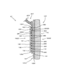
次に図6~図10を参照しつつ、清掃体ホルダ200と清掃体100の係合について説明する。図6に示すように、保持部材221はそれぞれ、保持空間130に挿入が可能とされている。保持部材221が挿入方向Y1に沿って保持空間130に挿入されることで、清掃体100が清掃体ホルダ200に保持される。一方、係合している清掃体ホルダ200と清掃体100とを分離するためには、清掃体ホルダ200を、引抜方向Y2に沿って保持空間130から引き抜く。
次に図6~図10を参照しつつ、清掃体ホルダ200と清掃体100の係合について説明する。図6に示すように、保持部材221はそれぞれ、保持空間130に挿入が可能とされている。保持部材221が挿入方向Y1に沿って保持空間130に挿入されることで、清掃体100が清掃体ホルダ200に保持される。一方、係合している清掃体ホルダ200と清掃体100とを分離するためには、清掃体ホルダ200を、引抜方向Y2に沿って保持空間130から引き抜く。
清掃体ホルダ200と清掃体100の係合状態においては、凸部260は、隣接する第2の接合部152同士の間に配置される。これにより、清掃体ホルダ200と清掃体100の係合状態が確実に維持される。
また、押え板270は、保持部材221とともに基部120を挟持する。
また、押え板270は、保持部材221とともに基部120を挟持する。
図7は、清掃体100と保持具200の構成要素同士の関係を示す説明図である。清掃体100は、長手方向Yにおける両端部100Y同士の間を結んだ直線において、最も短い長さを有する直線により規定される距離D100を形成する。なお、距離D100は、清掃体100に形成されるとしたが、刷毛部110に形成されるということもできる。
基部120は、長手方向Yにおける両端部120Y同士の間を結んだ直線において、最も短い長さを有する直線により規定される距離D200を有する。長手方向Yにおいて、基部120は、刷毛部110よりも短く形成されている。そして、基部120は、長手方向Yにおいて刷毛部110の中央領域に配置されている。よって、清掃体100(刷毛部110)において、基部120が形成されていない領域には、距離D300が形成される。距離D300は、清掃体100における長手方向Y上の一方の端部100Y側と、他方の端部100Y側とにそれぞれ形成される。なお、距離300Dは、基部120における長手方向Y上の端部120Yと、清掃体100(刷毛部110)における長手方向Y上の端部100Yとを結んだ直線において、最も短い長さを有する直線により規定されるということもできる。
基部120は、長手方向Yにおける両端部120Y同士の間を結んだ直線において、最も短い長さを有する直線により規定される距離D200を有する。長手方向Yにおいて、基部120は、刷毛部110よりも短く形成されている。そして、基部120は、長手方向Yにおいて刷毛部110の中央領域に配置されている。よって、清掃体100(刷毛部110)において、基部120が形成されていない領域には、距離D300が形成される。距離D300は、清掃体100における長手方向Y上の一方の端部100Y側と、他方の端部100Y側とにそれぞれ形成される。なお、距離300Dは、基部120における長手方向Y上の端部120Yと、清掃体100(刷毛部110)における長手方向Y上の端部100Yとを結んだ直線において、最も短い長さを有する直線により規定されるということもできる。
保持具200は、長手方向Yにおける保持部材221の根本部分と、先端部240とを結んだ直線において、最も短い長さを有する直線により規定される距離D400を形成する。
本発明における実施形態においては、距離D400の長さは、距離D200と一方の距離D300とを合計した長さよりも短く形成される。すなわち、清掃体100における保持部材221の先端部240側の領域においては、保持部材221が配置されない領域が形成される。本発明における実施形態においては、距離D400は、距離D200よりも若干長く形成されている。よって、清掃体100における保持部材221が配置されない領域は、保持部材221の先端部240と、清掃体100の長手方向Y上における端部100Yとを結んだ直線において、最も短い長さを有する直線により規定される距離D500を形成する。距離D500の長さは、距離D300の長さよりも短くなる。
距離D500が存在する領域においては、清掃体100は保持部材221により支持されない。一方、距離D500が存在する領域においては、高剛性領域141Aが形成されている。よって、ユーザが清掃用具Aを使用した場合であっても、距離D500が存在する領域が大きく垂れ下がることはない。
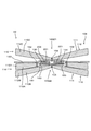
図8は図6におけるI-I線の断面を示す図であり、図9は図6におけるII-II線の断面を示す図である。第2刷毛領域110B(第2繊維集合体112B)は、硬化部140と対向する硬化部対向領域160を有する。硬化部対向領域160は、硬化部140と対向しているため、第1繊維集合体112Aの繊維113とは絡みにくい構成となる。すなわち、第1繊維集合体112Aと第2繊維集合体112Bは絡みにくい構成となる。
よって、ユーザによる清掃作業により、清掃体100により捕捉された塵芥が、繊維集合体112の奥の方(第2繊維集合体112Bからみて、第1繊維集合体112Aの方向)に移動しやすくなる。よって、より多くの塵芥を捕捉できることとなる。
よって、ユーザによる清掃作業により、清掃体100により捕捉された塵芥が、繊維集合体112の奥の方(第2繊維集合体112Bからみて、第1繊維集合体112Aの方向)に移動しやすくなる。よって、より多くの塵芥を捕捉できることとなる。
(作用)
本発明の実施形態に係る清掃用具Aの作用につき、図10に基づき説明する。
まず、ユーザは、ハンドル部210のハンドル211を把持し、清掃体100の挿入空間130に保持部材221を挿入する。この際、保持部材221の先端部240が、挿入空間130における硬化部140に当接される。挿入空間130の硬化部140は、低摩擦部131を形成している。すなわち、ユーザは、保持部材221の先端部240を低摩擦131に当接しつつ挿入することができる。よって、保持具200と清掃体100の装着作業が容易となる。
本発明の実施形態に係る清掃用具Aの作用につき、図10に基づき説明する。
まず、ユーザは、ハンドル部210のハンドル211を把持し、清掃体100の挿入空間130に保持部材221を挿入する。この際、保持部材221の先端部240が、挿入空間130における硬化部140に当接される。挿入空間130の硬化部140は、低摩擦部131を形成している。すなわち、ユーザは、保持部材221の先端部240を低摩擦131に当接しつつ挿入することができる。よって、保持具200と清掃体100の装着作業が容易となる。
次に、ユーザは、ハンドル部210のハンドル211を把持し、清掃体100を清掃対象へ当接させる。これにより、刷毛部110にて、清掃対象の塵芥を刷毛部110に捕集することや、払うことが可能となる。
この際、硬化部140と、硬化部対向領域160とにより、刷毛部110における第1繊維集合体112Aと第2繊維集合体112Bとが絡みにくい構成となっている。よって、清掃体100は、塵芥を効率的に捕捉することができる。
この際、硬化部140と、硬化部対向領域160とにより、刷毛部110における第1繊維集合体112Aと第2繊維集合体112Bとが絡みにくい構成となっている。よって、清掃体100は、塵芥を効率的に捕捉することができる。
また、ユーザが清掃作業を行っている場合は、清掃体100の他方の面100Z2が清掃対象に押し付けられる。これにより、清掃体保持部220の第1面220Z1が高摩擦部132に押し付けられる。よって、清掃中における保持具200と清掃体100との離脱を防止することができる。
なお、清掃用具Aの先端方向(ハンドル部210と対向する方向)における硬化部140は、高剛性部141を形成している。よって、清掃体100の先端方向が、下方(清掃対象に向かう方向)に垂れ下がることを防止することができる。
また、清掃用具Aの先端方向における硬化部140は、掻き出し部141Bを有する。さらに、掻き出し部141Bは、角部141B1を有する。よって、ユーザは、掻き出し部141Bや角部141B1を清掃対象に当接し、塵芥を掻き出すことが可能となる。
一方、ユーザが清掃用具Aにおける清掃体100を交換する場合は、保持具200を清掃体100から引き抜く。この際も、ユーザは、保持部材221の先端部240を低摩擦131に当接しつつ引き抜くことができる。よって、保持具200と清掃体100の離脱作業が容易となる。
(製造工程)
つぎに、図11~図22において、本発明に係る実施形態の清掃用具Aの製造方法を説明する。まず、具体的な製造工程の説明をする前に、本発明に係る繊維集合体112を形成する繊維113の説明を行う。
図11は、繊維集合体112を形成する繊維113である。なお、図11に係る繊維113は、外力がかかっていない静止状態を示す。繊維113は、捲縮繊維であるため、複数の屈曲部113Aを有し、ジグザグ状とされている。この屈曲部113Aはクリンプ部とも呼ばれる。
繊維113は、屈曲部113Aを有することにより、伸縮が可能となっている。図12は、静止状態の繊維113の両端部に対し、それぞれ対向する方向へ外力(張力)を加えた状態を示す。このように、繊維113は、屈曲部113A間の距離が離間することにより延びることが可能となる。一方、この外力を解除した状態においては、繊維113は、図12に示す延ばされた状態から、図11に示す静止状態へと復帰する。
図13は、第1製造工程を示すフローチャートである。製造工程は、第1刷毛領域110Aに硬化部140を形成する工程である第1工程S11と、第1刷毛領域110Aに基部120を積層するとともに、第1刷毛領域110Aと基部120とを接合部151および接合部152により接続する工程である第2工程S12と、第1刷毛領域110Aに第2刷毛領域110Bを積層するとともに、第1刷毛領域110Aと第2刷毛領域110Bとを接合部153により接続する工程である第3工程S13と、積層された基部120と、第1刷毛領域110Aと、第2刷毛領域110Bとを所定の位置にて切断することにより清掃体100を得る工程である第4工程S14とを有する。
図14は、第1工程S11を示す。第1工程S11では、第1刷毛領域110Aとなる第1刷毛資材110A1が供給される。第1刷毛資材110A1は繊維集合体112により形成される。第1刷毛資材110A1は、所定の領域が加熱される。これによって、繊維集合体112を構成する繊維113が溶着することにより硬化部140が形成される。この第1工程S11が、本発明に係る「前記刷毛部に硬化部を形成する工程」の一例である。
なお、本発明の製造工程においては、各資材は支持ロールRにより支持されるとともに、図示しない駆動機構により、機械方向Mに移送される。
なお、繊維集合体112における繊維配向方向は、機械方向Mとおおよそ一致する。
なお、本発明の製造工程においては、各資材は支持ロールRにより支持されるとともに、図示しない駆動機構により、機械方向Mに移送される。
なお、繊維集合体112における繊維配向方向は、機械方向Mとおおよそ一致する。
図15は、第2工程S12を示す。第2工程S12では、基部120を形成する基部資材1201が、第1刷毛資材110A1に対し供給される。そして、基部資材1201と第1刷毛資材110A1とが接合部150により接合される。接合部150は、基部資材1201と硬化部140とを接合する第1接合部151と、基部資材121と硬化部140を有さない第1刷毛資材110A1の所定領域とを接合する一対の第2接合部152とが設けられる。接合部150の形成にあっては、接合部150が形成される領域が加熱される。これによって、基部資材1201と硬化部140、および基部資材1201と第1刷毛資材110A1とが溶着される。この結果、機械方向Mに離間する一対の第2接合部152の間における、基部資材1201と第1刷毛資材110A1との間には保持空間130が形成される。
この、基部資材1201と第1刷毛資材110A1とに対し第2接合部152を形成する工程が、本発明に係る「前記刷毛部に前記基部を接続する工程と、前記刷毛部と前記基部の間に、前記保持部を挿入するための挿入部を形成する工程と、」の一例である。
この、基部資材1201と第1刷毛資材110A1とに対し第2接合部152を形成する工程が、本発明に係る「前記刷毛部に前記基部を接続する工程と、前記刷毛部と前記基部の間に、前記保持部を挿入するための挿入部を形成する工程と、」の一例である。
図16は、第3工程S13を示す。第3工程S13では、第1刷毛資材110A1における基部資材120が配置されていない面に対して、第2刷毛領域110Bとなる第2刷毛資材110B1が供給される。第2刷毛資材110B1は、繊維集合体112により形成される。そして、接合部150として、第2刷毛資材110B1と、硬化部140とが第3接合部153により接合される。この第3接合部153は、第2刷毛資材110B1と硬化部140の所定領域を加熱することによる熱溶着により形成される。
図17は、第4工程S14を示す。第4工程S14では、積層されるとともに溶着された、基部資材1201と、第1刷毛資材110A1と、第2刷毛資材110B1とが所定領域にて切断される。
このようにして、本発明に係る清掃用具Aの清掃体100が製造される。
このようにして、本発明に係る清掃用具Aの清掃体100が製造される。
図18は、第2製造工程を示すフローチャートである。製造工程は、第1刷毛領域110Aに硬化部140を形成する工程である第1工程S21と、第1刷毛領域110Aに基部120を積層するとともに、第1刷毛領域110Aと基部120とを接合部152により接続する工程である第2工程S22と、第1刷毛領域110Aに第2刷毛領域110Bを積層するとともに、第1刷毛領域110Aと第2刷毛領域110Bとを接合部151および接合部153により接続する工程である第3工程S23と、積層された基部120と、第1刷毛領域110Aと、第2刷毛領域110Bとを所定の位置にて切断することにより清掃体100を得る工程である第4工程S24とを有する。
図19は、第1工程S21を示す。第1工程S21は、第1製造方法における第1工程S11と同様であるため説明を省略する。
図20は、第2工程S22を示す。第2工程S22では、基部120を形成する基部資材1201が、第1刷毛資材110A1に対し供給される。そして、基部資材1201と第1刷毛資材110A1とが接合部150により接合される。すなわち、接合部150として、基部資材121と、硬化部140を有さない第1刷毛資材110A1の所定領域とを接合する一対の第2接合部152が設けられる。接合部150の形成にあっては、接合部150が形成される領域が加熱される。これによって、基部資材1201と第1刷毛資材110A1とが溶着される。この結果、機械方向Mに離間する一対の第2接合部152の間における、基部資材1201と第1刷毛資材110A1との間には保持空間130が形成される。
この、基部資材1201と第1刷毛資材110A1とに対し第2接合部152を形成する工程が、本発明に係る「前記刷毛部に前記基部を接続する工程と、前記刷毛部と前記基部の間に、前記保持部を挿入するための挿入部を形成する工程と、」の一例である。
この、基部資材1201と第1刷毛資材110A1とに対し第2接合部152を形成する工程が、本発明に係る「前記刷毛部に前記基部を接続する工程と、前記刷毛部と前記基部の間に、前記保持部を挿入するための挿入部を形成する工程と、」の一例である。
図21は、第3工程S23を示す。第3工程S23では、第1刷毛資材110A1における基部資材120が配置されていない面に対して、第2刷毛領域110Bとなる第2刷毛資材110B1が供給される。第2刷毛資材110B1は、繊維集合体112により形成される。そして、接合部150として、基部資材1201と硬化部140とを接合する第1接合部151と、第2刷毛資材110B1と硬化部140とを接合する第3接合部153とが設けられる。第1接合部151および第3接合部153は、第2刷毛資材110B1と硬化部140の所定領域を加熱することによる熱溶着により形成される。
なお、第1接合部151および第3接合部153は、単一の熱溶着装置により設けられる。よって、第1接合部151と第3接合部153とを同時に形成することが可能となるため、安定した生産スピードを保つことが可能となる。
なお、第1接合部151および第3接合部153は、単一の熱溶着装置により設けられる。よって、第1接合部151と第3接合部153とを同時に形成することが可能となるため、安定した生産スピードを保つことが可能となる。
図22は、第4工程S24を示す。第4工程S24では、積層されるとともに溶着された、基部資材1201と、第1刷毛資材110A1と、第2刷毛資材110B1とが所定領域にて切断される。
このようにして、第2製造方法においても、本発明に係る清掃用具Aの清掃体100が製造される。
このようにして、第2製造方法においても、本発明に係る清掃用具Aの清掃体100が製造される。
なお、上述した図14~図17および図19~図22においては、刷毛部110を形成する繊維構成体111として繊維集合体112を使用した例を説明した。一方、繊維構成体111として不織布114を用いることができる。
さらに、上述した図14~図17および図19~図22においては、硬化部140が熱溶着により形成される例を説明した。一方、硬化部140を、繊維構成体111に含浸された含浸体を硬化させることにより形成することもできる。
さらに、上述した図14~図17および図19~図22においては、硬化部140が熱溶着により形成される例を説明した。一方、硬化部140を、繊維構成体111に含浸された含浸体を硬化させることにより形成することもできる。
なお、本発明は上記の実施の形態のみに限定されるものではなく、種々の応用や変形が考えられる。
以下、上記実施形態の変形例につき説明を行うが、上記実施形態における清掃用具Aと同一の構成にあっては、同一の符号を付すとともにその説明を省略する。
(第1変形例)
図23~図24に基づき第1変形例を説明する。なお、第1変形例に係る清掃用具A1は、上述の実施形態における清掃用具Aに比して、清掃体の構成が異なるものである。
すなわち、第1変形例に係る清掃体101は、接合部150として第1接合部151を有さないものである。このため、上述の実施形態に係る清掃体101においては、保持空間130が第1接合部151により二つの領域に区分されていたが、第1変形例に係る清掃体101においては、保持空間130は単一の領域を有するものである。
このように保持空間130が単一の領域を有するものであっても、保持空間130と、保持具200の清掃体保持部220との装着においては、上記実施形態の清掃用具Aと同様の作用および効果を奏するものである。
なお、第1変形例に係る清掃用具A1の保持具201は、実施形態Aに係る保持具200と同様の構成を有する。一方、第1変形例に係る清掃体101の保持空間130が単一であることから、保持具201の清掃体保持部220を単一の構成とすることも可能である。
(第2変形例)
図25に基づき第2変形例を説明する。なお、第2変形例に係る清掃用具A2は、上述の実施形態における清掃用具Aに比して、清掃体の構成が異なるものである。
すなわち、第2変形例に係る清掃体102は、接合部150として第2接合部152が、基部120と、第1刷毛領域110Aと、第3刷毛領域110Bの全てを溶着するものである。すなわち、清掃体102の他方の面100Z2においては、第2接合部152が存在する箇所と存在しない箇所が形成される。この内、他方の面100Z2における第2接合部152が存在しない箇所において、第2繊維集合体112Bは、第3接合部153に接合された固定端と、自由端とを有する。一方、他方の面100Z2における第2接合部152が存在する箇所において、第2繊維集合体112Bは、第2接合部152に接合された固定端と、自由端とを有する。すなわち、第2変形例に係る清掃用具A2において、第2繊維集合体112Bは、異なる長さの繊維を有する領域が混在することとなる。よって、この異なる長さの繊維を有する領域同士の間等にて塵芥を効果的に捕捉することが可能となる。
(第3変形例)
図26に基づき第3変形例を説明する。なお、第3変形例に係る清掃用具A3は、上述の実施形態における清掃用具Aに比して、清掃体の構成が異なるものである。なお、第3変形例に係る保持具203(図示しない)は、実施形態における保持具200と同様の構成を有する。
すなわち、第3変形例に係る清掃体103は、長手方向Yにおける硬化部140の形成領域が、基部120の存在する範囲内である。よって、硬化部140が形成されている領域においては、実施形態における清掃体100と同様に、低摩擦部131と、高摩擦部132と、硬化部対向領域160とを形成するものである。
一方、硬化部140が形成されていない領域である、刷毛部110において基部120が存在しない領域においては、特に硬化部対向領域160が形成されない。すなわち、硬化部140が形成されていない領域においては、第1繊維集合体112Aと、第2繊維集合体112Bが絡みやすい状況となる。この結果、硬化部140が存在する領域と、硬化部140が存在しない領域とでは、第1繊維集合体112Aと第2繊維集合体112Bとが絡む状況が異なる。よって、硬化部140が存在する領域の繊維集合体112と、硬化部140が存在しない領域の繊維集合体112との間には段差が生じやすい状況となる。この結果、当該段差にて塵芥を捕捉しやすい構造となる。
(第4変形例)
図27に基づき第4変形例を説明する。なお、第4変形例に係る清掃用具A4は、上述の実施形態における清掃用具Aに比して、清掃体の構成が異なるものである。なお、第4変形例に係る保持具204(図示しない)は、実施形態における保持具200と同様の構成を有する。
すなわち、第4変形例に係る清掃体104は、長手方向Yにおける硬化部140の形成領域が、基部120の存在しない領域である。よって、硬化部140が形成されている領域においては、実施形態における清掃体100と同様に、高剛性部141と、高剛性端部領域141Aと、掻き出し部141Bと、角部141Bと、硬化部対向領域160とを形成するものである。この場合、基部120が存在しない領域とは、刷毛部110において、清掃体104における長手方向端部100Yと、この長手方向端部100Yと最も近い基部120の長手方向端部120Yとの間と言うこともできる。
一方、硬化部140が形成されていない領域である、刷毛部110において基部120が存在する領域においては、特に硬化部対向領域160が形成されない。すなわち、硬化部140が形成されていない領域においては、第1繊維集合体112Aと、第2繊維集合体112Bが絡みやすい状況となる。この結果、硬化部140が存在する領域と、硬化部140が存在しない領域とでは、第1繊維集合体112Aと第2繊維集合体112Bとが絡む状況が異なる。よって、硬化部140が存在する領域の繊維集合体112と、硬化部140が存在しない領域の繊維集合体112との間には段差が生じやすい状況となる。この結果、当該段差にて塵芥を捕捉しやすい構造となる。
(第5変形例)
図28に基づき第5変形例を説明する。なお、第5変形例に係る清掃用具A5は、上述の実施形態における清掃用具Aに比して、清掃体の構成が異なるものである。なお、第5変形例に係る保持具205(図示しない)は、実施形態における保持具200と同様の構成を有する。
すなわち、第5変形例に係る清掃体105は、長手方向Yにおける硬化部140の形成領域が、基部120と刷毛部110の境界である境界領域133を含む領域である。よって、硬化部140が形成されている領域においては、実施形態における清掃体100と同様に、低摩擦部131と、高摩擦部132と、高剛性部141と、硬化部対向領域160とを形成するものである。
一方、硬化部140が形成されていない領域においては、特に硬化部対向領域160が形成されない。すなわち、硬化部140が形成されていない領域においては、第1繊維集合体112Aと、第2繊維集合体112Bが絡みやすい状況となる。この結果、硬化部140が存在する領域と、硬化部140が存在しない領域とでは、第1繊維集合体112Aと第2繊維集合体112Bとが絡む状況が異なる。よって、硬化部140が存在する領域の繊維集合体112と、硬化部140が存在しない領域の繊維集合体112との間には段差が生じやすい状況となる。この結果、当該段差にて塵芥を捕捉しやすい構造となる。
(第6変形例)
図29~図31に基づき第6変形例を説明する。なお、第6変形例に係る清掃用具A6は、上述の実施形態における清掃用具Aに比して、清掃体の構成が異なるものである
すなわち、第6変形例に係る清掃体106は、刷毛部110を形成する繊維構成体111が不織布114により形成されるものである。すなわち、第1刷毛領域110Aは第1不織布114Aにより形成され、第2刷毛領域110Bは第2不織布114Bにより形成されている。なお、第6変形例においては、第1不織布114が一つ、第2不織布114Bが二つの不織布114により形成されているが、その枚数は任意である。また、不織布114は、基部120と同様の構成の不織布を使用することができる。一方、不織布114として基部120とは異なる不織布を使用することもできる。また、第1不織布114Aと第2不織布114Bとは同一の不織布114を用いることができる。一方、第1不織布114Aと第2不織布114Bとは異なる不織布114を用いることができる。
なお、基部120および不織布114には、切込み部171と短冊部170とが形成されている。
清掃体106においても、硬化部140が形成されて。よって、清掃体106は、実施形態における清掃体100と同様に、低摩擦部131と、高摩擦部132と、高剛性部141と、高剛性端部領域141Aと、掻き出し部141Bと、角部141Bと、硬化部対向領域160とを形成するものである。
よって、第6変形例に係る清掃体106においても、実施形態に係る清掃体100と同様の作用および効果を奏するものである。
(第7変形例)
図32に基づき第7変形例を説明する。なお、第7変形例に係る清掃用具A7は、上述の実施形態における清掃用具Aに比して、保持具の構成が異なるものである
すなわち、第7変形例に係る保持具207は、清掃体保持部220の第1面220Z1に抵抗部280を設けたものである。抵抗部280は、高摩擦部132との抵抗を増加させる構成を有する。具体的には、第1面220Z1から突出する凸部により構成されている。さらに、この凸部は先端が尖った頂部を有する。さらに、この頂部はハンドル部210の方向に向けられている。この構成により、ユーザが清掃体保持部220を保持空間130に挿入する際には、大きな抵抗を受けることが無い。また、ユーザが清掃作業を行っている場合には、抵抗部280と高摩擦部132の間に高い摩擦力が発生するため、清掃体107と保持具207が離脱しにくい構成となる。
(第8変形例)
図33に基づき第8変形例を説明する。なお、第8変形例に係る清掃用具A8は、上述の実施形態における清掃用具Aに比して、清掃体の構成が異なるものである
すなわち、第8変形例に係る清掃体108は、清掃体108における一方の面100Z1側に、第3刷毛領域110Cとして第3繊維集合体112Cを設けたものである。第3繊維集合体112Cは、第4接合部154によって基部120に接合される。
第8変形例に係る清掃体108は、実施形態に係る清掃体100が奏する作用および効果を奏するものである。さらに、清掃体108における他方の面100Z2側のみではなく、一方の面100Z1側でも清掃を行うことが可能となる。
図33に基づき第8変形例を説明する。なお、第8変形例に係る清掃用具A8は、上述の実施形態における清掃用具Aに比して、清掃体の構成が異なるものである
すなわち、第8変形例に係る清掃体108は、清掃体108における一方の面100Z1側に、第3刷毛領域110Cとして第3繊維集合体112Cを設けたものである。第3繊維集合体112Cは、第4接合部154によって基部120に接合される。
第8変形例に係る清掃体108は、実施形態に係る清掃体100が奏する作用および効果を奏するものである。さらに、清掃体108における他方の面100Z2側のみではなく、一方の面100Z1側でも清掃を行うことが可能となる。
本発明に係る清掃用具にあっては、上述した実施形態および第1~第8変形例に記載した構成にのみ限定されるものではない。すなわち、実施形態および第1~第8変形例に記載した構成を適宜組み合わせることが可能である。また、さらに他の構成の変形例とすることが可能である。
(実施の形態ないし実施例本発明の各構成要素の対応について)
清掃用具A、A1、A2、A3、A4、A5、A6、A7、A8は、本発明に係る「清掃用具」の一例である。清掃体100、101、102、103、104、105、106、107、108は、本発明に係る「清掃シート」の一例である。清掃体ホルダ200、201、202、203、204、205、206、207、208は、本発明に係る「保持具」の一例である。長手方向Yは、本発明に係る「長手方向」の一例である。長手交差方向Xは、本発明に係る「長手交差方向」の一例である。清掃体保持部220は、本発明に係る「保持部」の一例である。ハンドル部210は、本発明に係る「把持部」の一例である。基部120は、本発明に係る「基部」の一例である。刷毛部110は、本発明に係る「刷毛部」の一例である。繊維構成体111は、本発明に係る「繊維構成体」の一例である。繊維113は、本発明に係る「繊維」の一例である。繊維集合体112は、本発明に係る「繊維集合体」の一例である。不織布114は、本発明に係る「繊維構成体を形成する不織布」の一例である。保持空間130は、本発明に係る「挿入部」の一例である。硬化部140は、本発明に係る「硬化部」の一例である。第1刷毛領域110Aは、本発明に係る「第1刷毛領域」の一例である。第2刷毛領域110Bは、本発明に係る「第2刷毛領域」の一例である。保持空間130は、本発明に係る「挿入部」の一例である。低摩擦部131は、本発明に係る「低摩擦部」の一例である。高剛性部141は、本発明に係る「高剛性部」の一例である。高剛性端部領域141Aは、本発明に係る「高剛性端部領域」の一例である。掻き出し部141Bは、本発明に係る「掻き出し部」の一例である。第1工程S11は、本発明に係る「前記刷毛部に硬化部を形成する工程」の一例である。基部資材1201と第1刷毛資材110A1とに対し第2接合部152を形成する工程は、本発明に係る「前記刷毛部に前記基部を接続する工程」の一例である。基部資材1201と第1刷毛資材110A1とに対し第2接合部152を形成する工程は、本発明に係る「前記刷毛部に前記基部を接続する工程と、前記刷毛部と前記基部の間に、前記保持部を挿入するための挿入部を形成する工程と、」の一例である。
清掃用具A、A1、A2、A3、A4、A5、A6、A7、A8は、本発明に係る「清掃用具」の一例である。清掃体100、101、102、103、104、105、106、107、108は、本発明に係る「清掃シート」の一例である。清掃体ホルダ200、201、202、203、204、205、206、207、208は、本発明に係る「保持具」の一例である。長手方向Yは、本発明に係る「長手方向」の一例である。長手交差方向Xは、本発明に係る「長手交差方向」の一例である。清掃体保持部220は、本発明に係る「保持部」の一例である。ハンドル部210は、本発明に係る「把持部」の一例である。基部120は、本発明に係る「基部」の一例である。刷毛部110は、本発明に係る「刷毛部」の一例である。繊維構成体111は、本発明に係る「繊維構成体」の一例である。繊維113は、本発明に係る「繊維」の一例である。繊維集合体112は、本発明に係る「繊維集合体」の一例である。不織布114は、本発明に係る「繊維構成体を形成する不織布」の一例である。保持空間130は、本発明に係る「挿入部」の一例である。硬化部140は、本発明に係る「硬化部」の一例である。第1刷毛領域110Aは、本発明に係る「第1刷毛領域」の一例である。第2刷毛領域110Bは、本発明に係る「第2刷毛領域」の一例である。保持空間130は、本発明に係る「挿入部」の一例である。低摩擦部131は、本発明に係る「低摩擦部」の一例である。高剛性部141は、本発明に係る「高剛性部」の一例である。高剛性端部領域141Aは、本発明に係る「高剛性端部領域」の一例である。掻き出し部141Bは、本発明に係る「掻き出し部」の一例である。第1工程S11は、本発明に係る「前記刷毛部に硬化部を形成する工程」の一例である。基部資材1201と第1刷毛資材110A1とに対し第2接合部152を形成する工程は、本発明に係る「前記刷毛部に前記基部を接続する工程」の一例である。基部資材1201と第1刷毛資材110A1とに対し第2接合部152を形成する工程は、本発明に係る「前記刷毛部に前記基部を接続する工程と、前記刷毛部と前記基部の間に、前記保持部を挿入するための挿入部を形成する工程と、」の一例である。
以上の発明の趣旨に鑑み、本発明に係る清掃用具は、下記の態様が構成可能である。
(態様1)
清掃シートと、前記清掃シートを保持する保持具とを有する清掃用具において、
前記清掃シートは、当該清掃シートに前記保持具を挿入する方向によって規定される長手方向と、前記長手方向と交差する方向によって規定される長手交差方向の双方に延在するように構成され、
前記保持具は、前記清掃シートを保持するための保持部と、前記保持部に連結されてユーザに把持される把持部とを有し、
前記清掃シートは、清掃対象を清掃可能に構成された刷毛部と、前記刷毛部が接続されるとともに前記長手方向における長さが前記刷毛部よりも短い不織布により形成された基部と、前記刷毛部と前記基部の間に形成されるとともに前記保持部が挿入される挿入部とを有し、
前記挿入部を形成する刷毛部における前記長手方向の領域には、硬化部が形成されることを特徴とする清掃用具。
(態様2)
態様1に記載された清掃用具であって、
前記刷毛部は繊維構成体により形成されることを特徴とする清掃用具。
態様1に記載された清掃用具であって、
前記刷毛部は繊維構成体により形成されることを特徴とする清掃用具。
(態様3)
態様2に記載された清掃用具であって、
前記繊維構成体は、所定の方向に配向性を有する複数の繊維による繊維集合体により形成されることを特徴とする清掃用具。
態様2に記載された清掃用具であって、
前記繊維構成体は、所定の方向に配向性を有する複数の繊維による繊維集合体により形成されることを特徴とする清掃用具。
(態様4)
態様2に記載された清掃用具であって、
前記繊維構成体は、不織布により形成されることを特徴とする清掃用具。
態様2に記載された清掃用具であって、
前記繊維構成体は、不織布により形成されることを特徴とする清掃用具。
(態様5)
態様1~4のいずれか1項に記載された清掃用具であって、
前記繊維構成体は熱溶着性を有する繊維により形成され、前記硬化部は、前記繊維構成体における熱溶着性繊維を溶着することにより形成されることを特徴とする清掃用具。
態様1~4のいずれか1項に記載された清掃用具であって、
前記繊維構成体は熱溶着性を有する繊維により形成され、前記硬化部は、前記繊維構成体における熱溶着性繊維を溶着することにより形成されることを特徴とする清掃用具。
(態様6)
態様1~4のいずれか1項に記載された清掃用具であって、
前記硬化部は、前記繊維構成体に含浸された含浸体が硬化することにより形成されることを特徴とする清掃用具。
態様1~4のいずれか1項に記載された清掃用具であって、
前記硬化部は、前記繊維構成体に含浸された含浸体が硬化することにより形成されることを特徴とする清掃用具。
(態様7)
態様1~6のいずれか1項に記載された清掃用具であって、
前記長手方向において、前記刷毛部の端部と前記基部の端部に亘る領域内に形成された前記硬化部は、前記刷毛部における前記硬化部が形成されていない領域に比して高い剛性を有する高剛性部を形成することを特徴とする清掃用具。
態様1~6のいずれか1項に記載された清掃用具であって、
前記長手方向において、前記刷毛部の端部と前記基部の端部に亘る領域内に形成された前記硬化部は、前記刷毛部における前記硬化部が形成されていない領域に比して高い剛性を有する高剛性部を形成することを特徴とする清掃用具。
(態様8)
態様7に記載された清掃用具であって、
前記高剛性部における前記長手方向上の端部を含む領域である高剛性端部領域は、清掃対象に当接される掻き出し部を形成することを特徴とする清掃用具。
態様7に記載された清掃用具であって、
前記高剛性部における前記長手方向上の端部を含む領域である高剛性端部領域は、清掃対象に当接される掻き出し部を形成することを特徴とする清掃用具。
(態様9)
態様1~8のいずれか1項に記載された清掃用具であって、
前記長手方向において、前記基部の両端部間に亘る領域内に形成された前記硬化部は、前記基部に比して低い摩擦係数を有する低摩擦部を形成することを特徴とする清掃用具。
態様1~8のいずれか1項に記載された清掃用具であって、
前記長手方向において、前記基部の両端部間に亘る領域内に形成された前記硬化部は、前記基部に比して低い摩擦係数を有する低摩擦部を形成することを特徴とする清掃用具。
(態様10)
態様9に記載された清掃用具であって、
前記長手方向において、前記基部における前記硬化部と対向する領域は、前記低摩擦部に比して高い摩擦係数を有する高摩擦部を形成することを特徴とする清掃用具。
態様9に記載された清掃用具であって、
前記長手方向において、前記基部における前記硬化部と対向する領域は、前記低摩擦部に比して高い摩擦係数を有する高摩擦部を形成することを特徴とする清掃用具。
(態様11)
態様1~10のいずれか1項に記載された清掃用具であって、
前記刷毛部は、前記硬化部が形成された第1刷毛領域と、前記硬化部が形成されていない第2刷毛領域とを有することを特徴とする清掃用具。
態様1~10のいずれか1項に記載された清掃用具であって、
前記刷毛部は、前記硬化部が形成された第1刷毛領域と、前記硬化部が形成されていない第2刷毛領域とを有することを特徴とする清掃用具。
(態様12)
態様1~11のいずれか1項に記載された清掃用具において、
前記刷毛部は、前記基部の一方の側に設けられていることを特徴とする清掃用具。
態様1~11のいずれか1項に記載された清掃用具において、
前記刷毛部は、前記基部の一方の側に設けられていることを特徴とする清掃用具。
(態様13)
態様1~11のいずれか1項に記載された清掃用具において、
前記刷毛部は、前記基部の一方の側および他方の側に設けられていることを特徴とする清掃用具。
態様1~11のいずれか1項に記載された清掃用具において、
前記刷毛部は、前記基部の一方の側および他方の側に設けられていることを特徴とする清掃用具。
(態様14)
態様1~13のいずれか1項に記載された清掃用具であって、
前記基部と刷毛部は、接合部により接合されていることを特徴とする清掃用具。
態様1~13のいずれか1項に記載された清掃用具であって、
前記基部と刷毛部は、接合部により接合されていることを特徴とする清掃用具。
(態様15)
態様14に記載された清掃用具であって、
前記接合部は、前記清掃体の前記長手交差方向の中心を通過する前記長手方向に沿って延びるとともに、前記基部と前記第1刷毛領域とを接合する第1接合部を有することを特徴とする清掃用具。
態様14に記載された清掃用具であって、
前記接合部は、前記清掃体の前記長手交差方向の中心を通過する前記長手方向に沿って延びるとともに、前記基部と前記第1刷毛領域とを接合する第1接合部を有することを特徴とする清掃用具。
(態様16)
態様14または15に記載された清掃用具であって、
前記接合部は、前記長手方向に沿って延びるとともに、前記基部と前記第1刷毛領域とを接合する一対の第2接合部を有することを特徴とする清掃用具。
態様14または15に記載された清掃用具であって、
前記接合部は、前記長手方向に沿って延びるとともに、前記基部と前記第1刷毛領域とを接合する一対の第2接合部を有することを特徴とする清掃用具。
(態様17)
態様16に記載された清掃用具であって、
前記挿入部は、前記長手方向に沿って延びる一対の前記第2接合部の間における、前記基部と前記刷毛部との間に形成されることを特徴とする清掃用具。
態様16に記載された清掃用具であって、
前記挿入部は、前記長手方向に沿って延びる一対の前記第2接合部の間における、前記基部と前記刷毛部との間に形成されることを特徴とする清掃用具。
(態様18)
態様16または17に記載された清掃用具であって、
前記第2接合部は、前記基部と、前記第1刷毛領域における前記硬化部が形成されていない領域とを接合することを特徴とする清掃用具。
態様16または17に記載された清掃用具であって、
前記第2接合部は、前記基部と、前記第1刷毛領域における前記硬化部が形成されていない領域とを接合することを特徴とする清掃用具。
(態様19)
態様14~18のいずれか1項に記載された清掃用具であって、
前記接合部は、前記清掃体の前記長手交差方向の中心を通過する前記長手方向に沿って延びるとともに、前記第1刷毛領域と前記第2刷毛領域とを接合する第3接合部を有することを特徴とする清掃用具。
態様14~18のいずれか1項に記載された清掃用具であって、
前記接合部は、前記清掃体の前記長手交差方向の中心を通過する前記長手方向に沿って延びるとともに、前記第1刷毛領域と前記第2刷毛領域とを接合する第3接合部を有することを特徴とする清掃用具。
(態様20)
態様1~19のいずれか1項に記載された清掃用具であって、
前記保持部は、前記清掃シートと前記保持具とを装着した状態において基部側に向けられる第1面と、当該第1面と対向する第2面とを有し、
前記第1面は、前記高摩擦部に対して抵抗を生ずるように形成された抵抗部を有することを特徴とする清掃用具。
態様1~19のいずれか1項に記載された清掃用具であって、
前記保持部は、前記清掃シートと前記保持具とを装着した状態において基部側に向けられる第1面と、当該第1面と対向する第2面とを有し、
前記第1面は、前記高摩擦部に対して抵抗を生ずるように形成された抵抗部を有することを特徴とする清掃用具。
(態様21)
清掃シートと、前記清掃シートを保持する保持具とを有する清掃用具の製造方法において、
前記清掃シートは、基部と、当該基部に接合された刷毛部を有する構成であって、
前記刷毛部に硬化部を形成する工程と、
前記刷毛部に前記基部を接続する工程と、
前記刷毛部と前記基部の間に、前記保持部を挿入するための挿入部を形成する工程と、
を有することを特徴とする清掃用具の製造方法。
清掃シートと、前記清掃シートを保持する保持具とを有する清掃用具の製造方法において、
前記清掃シートは、基部と、当該基部に接合された刷毛部を有する構成であって、
前記刷毛部に硬化部を形成する工程と、
前記刷毛部に前記基部を接続する工程と、
前記刷毛部と前記基部の間に、前記保持部を挿入するための挿入部を形成する工程と、
を有することを特徴とする清掃用具の製造方法。
(態様22)
態様21に記載された清掃用具の製造方法であって、
前記刷毛部は繊維構成体により形成されることを特徴とする清掃用具の製造方法。
態様21に記載された清掃用具の製造方法であって、
前記刷毛部は繊維構成体により形成されることを特徴とする清掃用具の製造方法。
(態様23)
態様22に記載された清掃用具の製造方法であって、
前記繊維構成体は、特定の方向に配向性を有する複数の繊維による繊維集合体により形成されることを特徴とする清掃用具の製造方法。
態様22に記載された清掃用具の製造方法であって、
前記繊維構成体は、特定の方向に配向性を有する複数の繊維による繊維集合体により形成されることを特徴とする清掃用具の製造方法。
(態様24)
態様22に記載された清掃用具の製造方法であって、
前記繊維構成体は、不織布により形成されることを特徴とする清掃用具の製造方法。
態様22に記載された清掃用具の製造方法であって、
前記繊維構成体は、不織布により形成されることを特徴とする清掃用具の製造方法。
(態様25)
態様21~24のいずれか1項に記載された清掃用具の製造方法であって、
前記繊維構成体は熱溶着性を有する繊維により形成され、前記硬化部は、前記繊維構成体における熱溶着性繊維を溶着することにより形成されることを特徴とする清掃用具の製造方法。
態様21~24のいずれか1項に記載された清掃用具の製造方法であって、
前記繊維構成体は熱溶着性を有する繊維により形成され、前記硬化部は、前記繊維構成体における熱溶着性繊維を溶着することにより形成されることを特徴とする清掃用具の製造方法。
(態様26)
態様21~25のいずれか1項に記載された清掃用具の製造方法であって、
前記硬化部は、前記繊維構成体に含浸された含浸体が硬化することにより形成されることを特徴とする清掃用具の製造方法。
態様21~25のいずれか1項に記載された清掃用具の製造方法であって、
前記硬化部は、前記繊維構成体に含浸された含浸体が硬化することにより形成されることを特徴とする清掃用具の製造方法。
A、A1、A2、A3、A4、A5、A6、A7、A8 清掃用具(清掃具)
Y 長手方向
Y1 挿入方向
Y2 引抜方向
X 長手交差方向
Z 厚み方向
100、101、102、103、104、105、106、107、108 清掃シート(清掃体)
100X 端部
100Y 端部
100Z1 一方の面
100Z2 他方の面
110 刷毛部
110A 第1刷毛領域
110A1 第1刷毛資材
110B 第2刷毛領域
110B1 第2刷毛資材
110C 第3刷毛領域
111 繊維構成体
112 繊維集合体
112A 第1繊維集合体
112B 第2繊維集合体
112C 第3繊維集合体
113 繊維
113A 屈曲部
114 不織布
114A 第1不織布
114B 第2不織布
120 基部
1201 基部資材
120Y 端部
120X 端部
120A 一方の面
120B 他方の面
121 保持領域
122 先端領域
130 保持空間(挿入部)
131 低摩擦部
132 高摩擦部
133 境界領域
140 硬化部
140X 端部
140Y 端部
141 高剛性部
141A 高剛性端部領域
141B 掻き出し部
141B1 角部
142 低剛性部
150 接合部
151 第1接合部
152 第2接合部
153 第3接合部
160 硬化部対向領域
170 短冊部
171 切込み部
200、201、202、203、204、205、206、207、208 保持具(清掃体ホルダ)
210 ハンドル部(把持部)
211 ハンドル
212 ハンドル接合部
220 清掃体保持部(保持部)
220Z1 第1面
220Z2 第2面
221 保持部材
230 連接部
240 先端部
250 中間部
260 凸部
261 第1凸部
262 第2凸部
270 押え板
280 抵抗部
S100 第1工程
S200 第2工程
S300 第3工程
D100 距離
D200 距離
D300 距離
D400 距離
D500 距離
Claims (18)
- 清掃シートと、前記清掃シートを保持する保持具とを有する清掃用具において、
前記清掃シートは、前記清掃シートに前記保持具を挿入する方向によって規定される長手方向と、前記長手方向と交差する方向によって規定される長手交差方向の双方に延在するように構成され、
前記保持具は、前記清掃シートを保持するための保持部と、前記保持部に連結されてユーザに把持される把持部とを有し、
前記清掃シートは、清掃対象を清掃可能に構成された刷毛部と、前記刷毛部が接続されるとともに前記長手方向における長さが前記刷毛部よりも短い不織布により形成された基部と、前記刷毛部と前記基部の間に形成されるとともに前記保持部が挿入される挿入部とを有し、
前記挿入部を形成する刷毛部における前記長手方向の領域には、硬化部が形成されることを特徴とする清掃用具。 - 請求項1に記載された清掃用具であって、
前記刷毛部は繊維構成体により形成されることを特徴とする清掃用具。 - 請求項2に記載された清掃用具であって、
前記繊維構成体は、所定の方向に配向性を有する複数の繊維による繊維集合体により形成されることを特徴とする清掃用具。 - 請求項2に記載された清掃用具であって、
前記繊維構成体は、不織布により形成されることを特徴とする清掃用具。 - 請求項1~4のいずれか1項に記載された清掃用具であって、
前記繊維構成体は熱溶着性を有する繊維により形成され、前記硬化部は、前記繊維構成体における熱溶着性繊維を溶着することにより形成されることを特徴とする清掃用具。 - 請求項1~4のいずれか1項に記載された清掃用具であって、
前記硬化部は、前記繊維構成体に含浸された含浸体が硬化することにより形成されることを特徴とする清掃用具。 - 請求項1~6のいずれか1項に記載された清掃用具であって、
前記長手方向において、前記刷毛部の端部と前記基部の端部に亘る領域内に形成された前記硬化部は、前記刷毛部における前記硬化部が形成されていない領域に比して高い剛性を有する高剛性部を形成することを特徴とする清掃用具。 - 請求項7に記載された清掃用具であって、
前記高剛性部における前記長手方向上の端部を含む領域である高剛性端部領域は、清掃対象に当接される掻き出し部を形成することを特徴とする清掃用具。 - 請求項1~8のいずれか1項に記載された清掃用具であって、
前記長手方向において、前記基部の両端部間に亘る領域内に形成された前記硬化部は、前記基部に比して低い摩擦係数を有する低摩擦部を形成することを特徴とする清掃用具。 - 請求項1~9のいずれか1項に記載された清掃用具であって、
前記刷毛部は、前記硬化部が形成された第1刷毛領域と、前記硬化部が形成されていない第2刷毛領域とを有することを特徴とする清掃用具。 - 請求項1~10のいずれか1項に記載された清掃用具において、
前記刷毛部は、前記基部の一方の面に設けられていることを特徴とする清掃用具。 - 請求項1~10のいずれか1項に記載された清掃用具において、
前記刷毛部は、前記基部の一方の面および他方の面に設けられていることを特徴とする清掃用具。 - 清掃シートと、前記清掃シートを保持する保持具とを有する清掃用具の製造方法において、
前記清掃シートは、基部と、前記基部に接合された刷毛部を有する構成であって、
前記刷毛部に硬化部を形成する工程と、
前記刷毛部に前記基部を接続する工程と、
前記刷毛部と前記基部の間に、前記保持部を挿入するための挿入部を形成する工程と、
を有することを特徴とする清掃用具の製造方法。 - 請求項13に記載された清掃用具の製造方法であって、
前記刷毛部は繊維構成体により形成されることを特徴とする清掃用具の製造方法。 - 請求項14に記載された清掃用具の製造方法であって、
前記繊維構成体は、特定の方向に配向性を有する複数の繊維による繊維集合体により形成されることを特徴とする清掃用具の製造方法。 - 請求項14に記載された清掃用具の製造方法であって、
前記繊維構成体は、不織布により形成されることを特徴とする清掃用具の製造方法。 - 請求項13~16のいずれか1項に記載された清掃用具の製造方法であって、
前記繊維構成体は熱溶着性を有する繊維により形成され、前記硬化部は、前記繊維構成体における熱溶着性繊維を溶着することにより形成されることを特徴とする清掃用具の製造方法。 - 請求項13~16のいずれか1項に記載された清掃用具の製造方法であって、
前記硬化部は、前記繊維構成体に含浸された含浸体が硬化することにより形成されることを特徴とする清掃用具の製造方法。
Priority Applications (1)
| Application Number | Priority Date | Filing Date | Title |
|---|---|---|---|
| CN201480048729.4A CN105517477B (zh) | 2013-09-03 | 2014-08-01 | 清扫用具以及清扫用具的制造方法 |
Applications Claiming Priority (2)
| Application Number | Priority Date | Filing Date | Title |
|---|---|---|---|
| JP2013182520A JP6228407B2 (ja) | 2013-09-03 | 2013-09-03 | 清掃用具および清掃用具の製造方法 |
| JP2013-182520 | 2013-09-03 |
Publications (1)
| Publication Number | Publication Date |
|---|---|
| WO2014204017A1 true WO2014204017A1 (ja) | 2014-12-24 |
Family
ID=52104738
Family Applications (1)
| Application Number | Title | Priority Date | Filing Date |
|---|---|---|---|
| PCT/JP2014/070384 Ceased WO2014204017A1 (ja) | 2013-09-03 | 2014-08-01 | 清掃用具および清掃用具の製造方法 |
Country Status (3)
| Country | Link |
|---|---|
| JP (1) | JP6228407B2 (ja) |
| CN (1) | CN105517477B (ja) |
| WO (1) | WO2014204017A1 (ja) |
Families Citing this family (1)
| Publication number | Priority date | Publication date | Assignee | Title |
|---|---|---|---|---|
| US5327789A (en) | 1992-04-03 | 1994-07-12 | Rosemount, Inc. | Electromagnetic detection system for variable area flowmeter |
Citations (5)
| Publication number | Priority date | Publication date | Assignee | Title |
|---|---|---|---|---|
| JP2002369783A (ja) * | 2000-07-10 | 2002-12-24 | Uni Charm Corp | 清掃用物品 |
| JP2007159612A (ja) * | 2005-12-09 | 2007-06-28 | Kao Corp | 清掃用物品 |
| JP2011104111A (ja) * | 2009-11-17 | 2011-06-02 | Kikuo Yamada | 清掃シート、および清掃具 |
| JP2011156295A (ja) * | 2010-02-03 | 2011-08-18 | Unicharm Corp | 清掃用具、清掃体 |
| JP2011161274A (ja) * | 2011-05-30 | 2011-08-25 | Unicharm Corp | 清掃用物品 |
Family Cites Families (5)
| Publication number | Priority date | Publication date | Assignee | Title |
|---|---|---|---|---|
| CN1555756A (zh) * | 2004-01-07 | 2004-12-22 | 刚 邵 | 一种拖把 |
| JP3110306U (ja) * | 2005-02-10 | 2005-06-16 | 健彰實業有限公司 | ほこり取り用具 |
| JP4817998B2 (ja) * | 2005-10-19 | 2011-11-16 | 花王株式会社 | 清掃具 |
| JP4709105B2 (ja) * | 2006-09-12 | 2011-06-22 | ユニ・チャーム株式会社 | 清掃体及び清掃用具 |
| JP4869984B2 (ja) * | 2007-03-05 | 2012-02-08 | 大日本印刷株式会社 | 清掃用具 |
-
2013
- 2013-09-03 JP JP2013182520A patent/JP6228407B2/ja active Active
-
2014
- 2014-08-01 WO PCT/JP2014/070384 patent/WO2014204017A1/ja not_active Ceased
- 2014-08-01 CN CN201480048729.4A patent/CN105517477B/zh not_active Expired - Fee Related
Patent Citations (5)
| Publication number | Priority date | Publication date | Assignee | Title |
|---|---|---|---|---|
| JP2002369783A (ja) * | 2000-07-10 | 2002-12-24 | Uni Charm Corp | 清掃用物品 |
| JP2007159612A (ja) * | 2005-12-09 | 2007-06-28 | Kao Corp | 清掃用物品 |
| JP2011104111A (ja) * | 2009-11-17 | 2011-06-02 | Kikuo Yamada | 清掃シート、および清掃具 |
| JP2011156295A (ja) * | 2010-02-03 | 2011-08-18 | Unicharm Corp | 清掃用具、清掃体 |
| JP2011161274A (ja) * | 2011-05-30 | 2011-08-25 | Unicharm Corp | 清掃用物品 |
Also Published As
| Publication number | Publication date |
|---|---|
| CN105517477A (zh) | 2016-04-20 |
| CN105517477B (zh) | 2017-12-15 |
| JP6228407B2 (ja) | 2017-11-08 |
| JP2015047413A (ja) | 2015-03-16 |
Similar Documents
| Publication | Publication Date | Title |
|---|---|---|
| JP5171348B2 (ja) | 清掃用具、清掃体 | |
| JP6323981B2 (ja) | 清掃具 | |
| JP6323980B2 (ja) | 清掃具 | |
| JP6228366B2 (ja) | 清掃具 | |
| JP6228407B2 (ja) | 清掃用具および清掃用具の製造方法 | |
| JP5657525B2 (ja) | 清掃用具、清掃体 | |
| JP5588431B2 (ja) | 清掃用具、清掃体 | |
| JP5503640B2 (ja) | 清掃用具、清掃体 | |
| JP6208949B2 (ja) | 清掃具 | |
| JP6126398B2 (ja) | 清掃具 | |
| JP6195863B2 (ja) | 清掃具の製造方法および清掃シートの製造方法 | |
| JP5968245B2 (ja) | 清掃具および清掃シートの製造方法 | |
| JP5973930B2 (ja) | 清掃具 | |
| JP6346586B2 (ja) | 清掃具 | |
| JP6060000B2 (ja) | 清掃具 | |
| JP6126399B2 (ja) | 清掃具および清掃シートの製造方法 | |
| JP6126397B2 (ja) | 清掃具 | |
| JP6239828B2 (ja) | 清掃具 | |
| JP2014150966A5 (ja) | ||
| JP2014150965A5 (ja) | ||
| US20150366429A1 (en) | Cleaning tool |
Legal Events
| Date | Code | Title | Description |
|---|---|---|---|
| 121 | Ep: the epo has been informed by wipo that ep was designated in this application |
Ref document number: 14813960 Country of ref document: EP Kind code of ref document: A1 |
|
| NENP | Non-entry into the national phase |
Ref country code: DE |
|
| WWE | Wipo information: entry into national phase |
Ref document number: IDP00201602069 Country of ref document: ID |
|
| 122 | Ep: pct application non-entry in european phase |
Ref document number: 14813960 Country of ref document: EP Kind code of ref document: A1 |