WO2014203307A1 - 偏光板保持体 - Google Patents
偏光板保持体 Download PDFInfo
- Publication number
- WO2014203307A1 WO2014203307A1 PCT/JP2013/066579 JP2013066579W WO2014203307A1 WO 2014203307 A1 WO2014203307 A1 WO 2014203307A1 JP 2013066579 W JP2013066579 W JP 2013066579W WO 2014203307 A1 WO2014203307 A1 WO 2014203307A1
- Authority
- WO
- WIPO (PCT)
- Prior art keywords
- polarizing plate
- holder
- film
- type polarizing
- frame
- Prior art date
- Legal status (The legal status is an assumption and is not a legal conclusion. Google has not performed a legal analysis and makes no representation as to the accuracy of the status listed.)
- Ceased
Links
Images




Classifications
-
- G—PHYSICS
- G02—OPTICS
- G02B—OPTICAL ELEMENTS, SYSTEMS OR APPARATUS
- G02B7/00—Mountings, adjusting means, or light-tight connections, for optical elements
- G02B7/006—Filter holders
-
- G—PHYSICS
- G03—PHOTOGRAPHY; CINEMATOGRAPHY; ANALOGOUS TECHNIQUES USING WAVES OTHER THAN OPTICAL WAVES; ELECTROGRAPHY; HOLOGRAPHY
- G03B—APPARATUS OR ARRANGEMENTS FOR TAKING PHOTOGRAPHS OR FOR PROJECTING OR VIEWING THEM; APPARATUS OR ARRANGEMENTS EMPLOYING ANALOGOUS TECHNIQUES USING WAVES OTHER THAN OPTICAL WAVES; ACCESSORIES THEREFOR
- G03B21/00—Projectors or projection-type viewers; Accessories therefor
- G03B21/14—Details
- G03B21/20—Lamp housings
- G03B21/2073—Polarisers in the lamp house
-
- G—PHYSICS
- G03—PHOTOGRAPHY; CINEMATOGRAPHY; ANALOGOUS TECHNIQUES USING WAVES OTHER THAN OPTICAL WAVES; ELECTROGRAPHY; HOLOGRAPHY
- G03B—APPARATUS OR ARRANGEMENTS FOR TAKING PHOTOGRAPHS OR FOR PROJECTING OR VIEWING THEM; APPARATUS OR ARRANGEMENTS EMPLOYING ANALOGOUS TECHNIQUES USING WAVES OTHER THAN OPTICAL WAVES; ACCESSORIES THEREFOR
- G03B21/00—Projectors or projection-type viewers; Accessories therefor
- G03B21/14—Details
- G03B21/20—Lamp housings
- G03B21/208—Homogenising, shaping of the illumination light
-
- G—PHYSICS
- G03—PHOTOGRAPHY; CINEMATOGRAPHY; ANALOGOUS TECHNIQUES USING WAVES OTHER THAN OPTICAL WAVES; ELECTROGRAPHY; HOLOGRAPHY
- G03B—APPARATUS OR ARRANGEMENTS FOR TAKING PHOTOGRAPHS OR FOR PROJECTING OR VIEWING THEM; APPARATUS OR ARRANGEMENTS EMPLOYING ANALOGOUS TECHNIQUES USING WAVES OTHER THAN OPTICAL WAVES; ACCESSORIES THEREFOR
- G03B33/00—Colour photography, other than mere exposure or projection of a colour film
- G03B33/10—Simultaneous recording or projection
- G03B33/12—Simultaneous recording or projection using beam-splitting or beam-combining systems, e.g. dichroic mirrors
Definitions
- the present invention relates to a polarizing plate holder used for a projector or the like.
- polarizing plates are respectively arranged on the incident side and the emission side of the liquid crystal panel.
- the polarizing plate disposed on the incident side of the liquid crystal panel has a function of aligning the polarization direction of light rays incident on the liquid crystal panel.
- the polarizing plate arranged on the emission side of the liquid crystal panel has a function of shielding light rays corresponding to the non-display portion of the image out of the light rays emitted from the liquid crystal panel.
- a polarizing plate that absorbs polarized light is used by being bonded to a glass substrate that functions as a heat radiating plate in order to release thermal energy from the absorbed polarized light.
- a polarizing plate that reflects polarized light a reflective polarizing plate
- a metal film is formed on the surface of a glass substrate, and a wire-like grid is formed on the metal film by a fine etching process.
- Both the absorption-type polarizing plate and the reflective-type polarizing plate require a glass substrate, and the glass substrate is required to have high transparency and heat dissipation performance. For this reason, expensive materials such as sapphire glass and quartz are used as the glass substrate, which is a cause of high cost.
- a film-type polarizing plate is an example of a reflective polarizing plate that does not use a glass substrate.
- a wire grid polarizing film (WGF: Wire Grid Film) (for example, Patent Document 1).
- WGF uses a triacetate cellulose (TAC) film as a substrate, a wire-like grid is formed on one surface of the TAC film, and a metal reflective coat is formed on the grid. Since WGF reflects polarized light that is shielded from light, the thermal energy stored in WGF is small, and a glass substrate that functions as a heat sink is not required.
- TAC triacetate cellulose
- the thickness of the polarizing plate using a general glass substrate is about 0.7 mm to 2.2 mm
- the film type WGF which is a polarizing plate
- the surface of the WGF is likely to be distorted such as waviness.
- the distortion of the surface of the polarizing plate causes the polarization characteristics of the polarizing plate to be distorted, and causes a decrease in luminance and color uniformity of the display image.
- An object of the present invention is to provide a polarizing plate holder in which distortion of a film-type polarizing plate is suppressed.
- the polarizing plate holder of the present invention includes a film-type polarizing plate and a holder having a frame portion that has an opening through which light passes and holds the film-type polarizing plate covering the opening in a tensioned state.
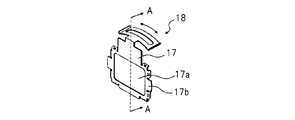
- FIG. 1A is a schematic perspective view of the polarizing plate holder 18, and FIG. 1B is a schematic view of the AA cross section of FIG.
- the polarizing plate holder 18 of the present invention has a holder 17 and a film-type polarizing plate 15.
- the holder 17 is made of an elastic material, and includes an opening 17a through which light passes, and a frame 17b that surrounds the opening 17a and to which the filter 15 is attached.
- the holder 17 can adjust the inclination of the film-type polarizing plate 15 with respect to the optical axis.
- the film-type polarizing plate 15 is, for example, a wire grid polarizing film (WGF).
- the film-type polarizing plate 15 has a cellulose triacetate (TAC) film 15a serving as a substrate and a wire-like grid formed on the surface (one surface) opposite to the TAC film 15a attached to the frame portion 17b. And a wire grid layer 15b having a metal reflective coating formed on the grid.
- TAC cellulose triacetate
- the film-type polarizing plate 15 is attached to the frame portion 17b of the holder 17 via the adhesive layer 19 so that the surface opposite to the surface on which the wire grid layer 15b is formed (the other surface) covers the opening 21. It has been. That is, the adhesive layer 27 does not exist in the portion of the film-type polarizing plate 15 through which light passes.
- the film-type polarizing plate 15 Since the film-type polarizing plate 15 is thin, it may be distorted when attached to the holder 17. Therefore, the holder 17 needs to pull the film-type polarizing plate 15 so that tension is generated.
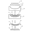
- Example 1 In FIG. 2, the manufacturing procedure of the polarizing plate holder 18 in the first embodiment is shown.
- a jig 21 having a curved portion 21a curved so as to be depressed is used.
- the jig 21 has a curved portion 21 a that is curved so as to be recessed on the surface that contacts the holder 17.
- the holder 17 is placed on the bending portion 21a and bent.
- the film-type polarizing plate 15 is bonded to the curved holder 17. Or it affixes so that the film type polarizing plate 15 may be pressed on the holder 17 arrange
- the polarizing plate holder 18 removed from the jig 21 becomes flat due to the restoring force of the holder 17. At this time, the film-type polarizing plate 15 is tensioned by being pulled by the holder 17, and distortions such as deflection and swell of the film polarizing plate 15 are removed.
- the curvature of the bending portion 21a of the jig 21 is desirably a curvature radius of 50 mm to 300 mm or an aspherical shape equivalent thereto.
- FIG. 3 shows a schematic configuration diagram of the front and bottom surfaces of the holder 37 used in the second embodiment.
- the holder 37 is gently curved so that the surface 37c to which the film-type polarizing plate 35 is attached has a convex shape. That is, the frame portion 37b is gently curved.
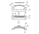
- FIG. 4 shows a manufacturing procedure of the polarizing plate holder 38 in the second embodiment.
- a holder 37 is attached to a jig 31 having a recess 31a having a flat bottom surface 31b.
- the surface 37c of the holder 37 on which the film-type polarizing plate 35 is attached is set to face the same direction as the bottom surface 31b of the recess 31a.
- a film-type polarizing plate 35 is attached to the holder 37.
- the film-type polarizing plate 35 is attached to the holder 37 while pushing the holder 37 so that the holder 37 becomes flat.
- the holder 37 and the film-type polarizing plate 35 are joined together in a curved state, and the polarizing plate holder in which the film-type polarizing plate 35 is attached to the holder 37. 38.
- the polarizing plate holder 38 is removed from the jig 31.
- the polarizing plate holder 38 removed from the jig 31 returns to the original curved state because the restoring force of the holder 37 makes the surface on which the film-type polarizing plate 35 is attached convex.
- the film-type polarizing plate 35 is tensioned by being pulled by the holder 37, and distortions such as deflection and swell of the film polarizing plate 35 are removed.
- the adhesion between the film-type polarizing plate 35 and the holder 37 must not be peeled off by the force generated when the film-type polarizing plate 35 is pulled by the restoring force of the holder 37, and the film-type polarizing plate 35 is bent or wavy. A certain tension must be applied so that no occurs. Therefore, it is desirable that the curvature of the curvature of the holder 37 is a curvature radius of 50 mm to 300 mm.
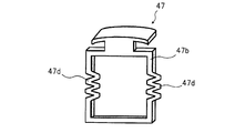
- FIG. 5 shows a schematic perspective view of the holder 47 used in the third embodiment.
- the holder 47 has a spring-shaped portion 47d formed on a part of the frame portion 47b. Specifically, a spring-shaped portion 47d that can be expanded and contracted like a spring is formed on one set of opposing sides of the frame portion 47b that consists of two opposing sides.
- FIG. 6 shows a manufacturing procedure of the polarizing plate holder 48 in the third embodiment.
- the jig 41 used in the present embodiment includes a flat base portion 41a, a wall portion 41b protruding from the base portion 41a, and a pressing portion 41c movable on the base portion 41a so as to be close to or away from the wall portion 41b. Consists of.
- the holder 47 is arranged on the base 41a so that the frame 47b is horizontal. Then, the pushing portion 41c is moved to the wall portion 41b side, and the holder 47 is pushed in. The holder 47 pushed in by the pushing portion 41c is contracted by the action of the spring-shaped portion 47d. In this state, the film-type polarizing plate 45 is attached to the holder 47. By attaching the film-type polarizing plate 45 to the holder 47 in this way, the holder 47 and the film-type polarizing plate 45 are coupled in a state in which the holder 47 is contracted, and the polarizing plate 45 is attached with the film-type polarizing plate 45. A plate holder 48 is obtained. Next, the polarizing plate holder 48 is removed from the jig 41.
- the spring-shaped portion 47d of the holder 47 tries to return to its original shape by elastic force.
- the film-type polarizing plate 45 is tensioned by being pulled by the holder 47, and distortions such as deflection and swell of the film polarizing plate 45 are removed.
- Example 4 In Example 1 to Example 3 described above, from the free state where no external force is applied to the holder, the surface of the holder on which the film-type polarizing plate is attached is deformed so as to shrink, and then the film-type polarizing plate is attached to the holder. Moreover, the tension
- FIG. 7 shows a schematic perspective view of the holder 57 used in the fourth embodiment.
- the holder 57 includes a pair of first claws 57e facing each other on one set of sides of the frame portion 57b composed of two pairs of facing sides, and a pair of second claw facing each other on the other set of sides.
- a claw 57f is provided.
- the first claw 57e and the second claw 57f are displaced in the thickness direction of the holder 57, and the film-type polarizing plate 55 is attached between the first claw 57e and the second claw 57f. Further, a reinforcing frame 56 described later can be held.
- the first claw 57e and the second claw 57f are configured such that the displacement of the holder 57 in the thickness direction is smaller than the thickness of the reinforcing frame 56.
- FIG. 8 is a schematic view showing a state where the film-type polarizing plate 55 is attached to the reinforcing frame 56
- FIG. 9 is a schematic view of the polarizing plate holding body 58 with the reinforcing frame 56 attached to the holder 57.
- the film-type polarizing plate 55 is attached to the reinforcing frame 56 composed of two opposing sides.
- the reinforcing frame 56 is open at a portion through which light passes.
- the reinforcing frame 56 to which the film polarizing plate 55 is attached is held so as to be sandwiched between the first claw 57e and the second claw 57f, and the polarizing plate holding body 58 is completed.
- the displacement in the thickness direction of the holder 57 is smaller than the thickness of the reinforcing frame 56.
- the reinforcing frame 56 held by the first claw 57e and the second claw 57f is curved because the first claw 57e and the second claw 57f are pushed in the opposite directions. Since the reinforcing frame 56 is curved, the film-type polarizing plate 55 is similarly bent, the film-type polarizing plate 55 is stretched and tension is generated, and distortions such as deflection and waviness of the film-type polarizing plate 55 are removed.
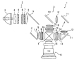
- FIG. 10 shows a schematic configuration diagram of an embodiment of a projector using the polarizing plate holder of the present invention.
- the projector 1 includes an illumination optical system 2, a color separation optical system 3, a light modulation unit 4, a cross dichroic prism 5 that is a light combining optical system, and a projection lens 6 that is a projection optical system.
- the illumination optical system 2 includes a light source 3, a concave lens 4, a first lens array 5, a second lens array 6, a polarization conversion element 7, and a field lens 8.
- the light emitted from the light source 3 includes blue light, green light, and red light.
- the concave lens 4 emits the light irradiated from the light source 3 and incident on the concave lens 4 as parallel light.
- the light emitted from the concave lens 4 passes through the first lens array 5 and the second lens array 6 and enters the polarization conversion element 7.
- the polarization direction of the incident light is aligned in one direction and becomes linearly polarized light. That is, the polarization directions of blue (B) light, green (G) light, and red (R) light are aligned in one direction.
- the light emitted from the polarization conversion element 7 is collected by the field lens 8.
- the color separation optical system 3 includes a first dichroic mirror 9, a second dichroic mirror 10, a reflection mirror 11, a relay lens 12, and a condenser lens 13.
- the first dichroic mirror 9 and the second dichroic mirror 10 can reflect light in a specific wavelength range.
- the light emitted from the illumination optical system 2 is separated into B light, G light, and R light, and one of the liquid crystal panels 14 that are light modulation elements of the light modulation unit 4 described later. Lead to.
- the light irradiated from the illumination optical system 2 reflects one of B light, G light, and R light, for example, B light, and transmits G light and R light by the first dichroic mirror 9.
- the B light reflected by the first dichroic mirror 9 goes to the liquid crystal panel 14 via the reflection mirror 11 and the condenser lens 13.
- G light and R light transmitted through the first dichroic mirror 9 are reflected by the second dichroic mirror 10, and the R light passes through the second dichroic mirror 10.
- the G light reflected by the second dichroic mirror 10 goes to the liquid crystal panel 14 via the condenser lens 13.
- the R light transmitted through the second dichroic mirror 10 goes to the liquid crystal panel 14 through the relay lens 12, the reflection mirror 11, the relay lens 12, the reflection mirror 11, and the condenser lens 13.
- the light modulation unit 4 includes three liquid crystal panels 14 that are light modulation elements, a polarizing plate holder 18 having a film-type polarizing plate disposed on the incident side of each liquid crystal panel 14, and the emission side of each liquid crystal panel 14.
- the B light, G light, and R light incident from the color separation optical system 3 are aligned in the polarization direction by the polarizing plate holder 18 and enter the liquid crystal panel 14.
- the B light, G light, and R light respectively incident on the liquid crystal panel 14 are modulated according to the level of the video signal of each color.
- the B light, G light, and R light emitted from the liquid crystal panel 14 are transmitted through the absorption polarizing plate 16 with their polarization directions aligned.
- the image light formed by the cross dichroic prism 5 is magnified by a projection lens 6 at a desired magnification, and a color image is projected on a screen (not shown).
- the polarizing plate holder 18 having a film-type polarizing plate is disposed on the incident side of the liquid crystal panel 14, and the absorbing polarizing plate is disposed on the outgoing side of the liquid crystal panel 14.
- the polarizing plate holder 18 may be disposed also on the emission side.
Landscapes
- Physics & Mathematics (AREA)
- General Physics & Mathematics (AREA)
- Optics & Photonics (AREA)
- Polarising Elements (AREA)
- Liquid Crystal (AREA)
- Projection Apparatus (AREA)
Abstract
本発明の目的は、フィルム型偏光板の歪みが抑制された偏光板保持体を提供することにある。本発明の偏光板保持体は、フィルム型偏光板と、光が通過する開口部を備え、開口部を覆うフィルム型偏光板を張力がかかる状態で保持する枠部を有するホルダと、を有する。
Description
本発明は、プロジェクタなどに使用される偏光板保持体に関する。
光変調素子として液晶パネルを使用するプロジェクタの光学系において、液晶パネルの入射側と出射側にそれぞれ偏光板が配置される。液晶パネルの入射側に配置される偏光板は、液晶パネルに入射する光線の偏光方向を揃える働きがある。一方、液晶パネルの出射側に配置される偏光板は、液晶パネルから出射する光線のうち、画像の非表示部分に該当する光線を遮光する働きがある。
偏光板が一方向の偏光を透過させ、他方向の偏光を遮光する方法として、他方の偏光を吸収する方法と反射する方法がある。偏光を吸収する偏光板(吸収型偏光板)は、吸収した偏光による熱エネルギーを放出するため、放熱板として機能するガラス基板に貼り合わされて使用される。一方、偏光を反射する偏光板(反射型偏光板)は、ガラス基板の表面に金属膜が形成され、その金属膜に微細エッチング処理にてワイヤ状のグリッドが形成されている。
吸収型偏光板や反射型偏光板はいずれもガラス基板を必要としており、そのガラス基板には透過性や放熱性が高い性能が要求される。そのため、ガラス基板としてサファイアガラスや水晶など高価な材料が用いられており、このことが高コストの要因となっている。
そこで、ガラス基板を用いない反射型偏光板として、フィルム型偏光板が挙げられる。フィルム型偏光板の一例として、ワイヤグリッド偏光フィルム(WGF:Wire Grid Film)がある(例えば特許文献1)。WGFはトリアセテートセルロース(TAC:Triacetylcellulose)フィルムを基板とし、TACフィルムの一方の面にワイヤ状のグリッドが形成され、グリッド上に金属による反射コートが形成されている。WGFは遮光する偏光を反射するため、WGFに蓄積される熱エネルギーは小さく、放熱板として機能するガラス基板が不要となる。
フィルム型偏光板とフィルム型偏光板を保持するホルダとで偏光板保持体を構成する場合、一般的なガラス基板を用いる偏光板の厚さは約0.7mm~2.2mmに対し、フィルム型偏光板であるWGFは、基板となるTACフィルムが薄いため、厚さが約0.1mmと薄い。そのため、WFGをホルダに取付けたときに、WGFの表面にうねりなどの歪が生じやすい。偏光板の表面の歪は、偏光板の偏光特性を狂わせ、表示画像の輝度や色味の均一性を低下させる要因となる。
本発明の目的は、フィルム型偏光板の歪みが抑制された偏光板保持体を提供することにある。
本発明の偏光板保持体は、フィルム型偏光板と、光が通過する開口部を備え、開口部を覆うフィルム型偏光板を張力がかかる状態で保持する枠部を有するホルダと、を有する。
本発明のフィルム型偏光板の保持構造について、図面を参照して説明する。
図1Aに、偏光板保持体18の概略斜視図を、図1Bに、図1のAA断面の概略図を示す。
本発明の偏光板保持体18は、ホルダ17とフィルム型偏光板15とを有する。ホルダ17は、弾性材料からなり、光が通過する開口部17aと、開口部17aを囲み、フィルタ15が貼り付けられる枠部17bと、を有している。また、ホルダ17は、フィルム型偏光板15の光軸に対する傾きを調節可能である。
フィルム型偏光板15は、例えばワイヤグリッド偏光フィルム(WGF)である。フィルム型偏光板15は、基板となるセルローストリアセテート(TAC)フィルム15aと、TACフィルム15aの、枠部17bに貼りつけられるのとは反対の面(一方の面)側にワイヤ状のグリッドが形成され、そのグリッド上に金属による反射コートが形成されたワイヤグリッド層15bと、を有している。
フィルム型偏光板15は、ワイヤグリッド層15bが形成された面とは反対の面(他方の面)が開口部21を覆うように、接着層19を介してホルダ17の枠部17bに貼りつけられている。つまり、フィルム型偏光板15の、光が通過する部分には接着層27は存在しない。
フィルム型偏光板15は薄いため、ホルダ17に取付けられたときに歪む可能性がある。そのため、ホルダ17は、フィルム型偏光板15を張力が生じるように引っ張る必要がある。
そこで、フィルム型偏光板15がホルダ17に取付けられたときに、ホルダ17によって張力が生じるようにする方法を以下で説明する。
(実施例1)
図2に、第1の実施例における偏光板保持体18の製造手順を示す。本実施例では、窪むように湾曲した湾曲部21aを有する治具21を利用する。
図2に、第1の実施例における偏光板保持体18の製造手順を示す。本実施例では、窪むように湾曲した湾曲部21aを有する治具21を利用する。
治具21は、ホルダ17と接触する面に、窪むように湾曲する湾曲部21aを有している。湾曲部21aにホルダ17を配置して湾曲させる。次に、湾曲した状態のホルダ17にフィルム型偏光板15を貼りあわせる。あるいは、湾曲部21a上に配置したホルダ17に、フィルム型偏光板15を押すように貼りつける。このようにホルダ17にフィルム型偏光板15を貼りつけることで、ホルダ17とフィルム型偏光板15がともに湾曲した状態で結合し、ホルダ17にフィルム型偏光板15が取り付けられた偏光板保持体18となる。次に、治具21から偏光板保持体18を取り外す。
治具21から取り外された偏光板保持体18は、ホルダ17の復元力により平らな状態になる。このとき、フィルム型偏光板15にはホルダ17に引っ張られることで張力が働き、フィルム偏光板15のたわみやうねり等の歪が除去される。
なお、ホルダ17の復元力によりフィルム型偏光板15が引っ張られる際に生じる力でフィルム型偏光板15とホルダ17との接着が剥がれてはならず、かつフィルム型偏光板15にはたわみやうねりが生じないように一定の張力が働かなければならない。そのため、治具21の湾曲部21aの曲率は、曲率半径が50mm~300mmまたは、それに準ずる非球面の形状が望ましい。
(実施例2)
図3に、第2の実施例に用いるホルダ37の正面及び底面の概略構成図を示す。ホルダ37はフィルム型偏光板35が貼り付けられる面37cが凸形状となるように緩やかに湾曲している。つまり枠部37bが緩やかに湾曲している。
図3に、第2の実施例に用いるホルダ37の正面及び底面の概略構成図を示す。ホルダ37はフィルム型偏光板35が貼り付けられる面37cが凸形状となるように緩やかに湾曲している。つまり枠部37bが緩やかに湾曲している。
図4に、第2の実施例における偏光板保持体38の製造手順を示す。底面31bが平らになっている凹部31aを有する治具31に、ホルダ37が取り付けられる。このとき、ホルダ37の、フィルム型偏光板35が貼り付けられる面37cと凹部31aの底面31bとが同じ方向を向くようにする。
そして、フィルム型偏光板35をホルダ37に貼りつける。このとき、ホルダ37が平らになるようにホルダ37を押し込みながら、フィルム型偏光板35をホルダ37に貼りつける。このようにホルダ37にフィルム型偏光板35を貼りつけることで、ホルダ37とフィルム型偏光板35がともに湾曲した状態で結合し、ホルダ37にフィルム型偏光板35が取り付けられた偏光板保持体38となる。
そして、治具31から偏光板保持体38を取り外す。治具31から取り外された偏光板保持体38は、ホルダ37の復元力により、フィルム型偏光板35が貼り付けられた面が凸形状になる、つまり元の湾曲した状態に戻る。ホルダ37が湾曲した状態に戻ると、フィルム型偏光板35にはホルダ37に引っ張られることで張力が働き、フィルム偏光板35のたわみやうねり等の歪が除去される。
なお、ホルダ37の復元力によりフィルム型偏光板35が引っ張られる際に生じる力でフィルム型偏光板35とホルダ37との接着が剥がれてはならず、かつフィルム型偏光板35にはたわみやうねりが生じないように一定の張力が働かなければならない。そのため、ホルダ37の湾曲の曲率は、曲率半径が50mm~300mmが望ましい。
(実施例3)
図5に、第3の実施例に用いるホルダ47の概略斜視図を示す。ホルダ47は枠部47bの一部にバネ形状部47dが形成されている。具体的には、対向する2組の辺からなる枠部47bのうち対向する1組の辺にバネのように伸び縮み可能なバネ形状部47dが形成されている。
図5に、第3の実施例に用いるホルダ47の概略斜視図を示す。ホルダ47は枠部47bの一部にバネ形状部47dが形成されている。具体的には、対向する2組の辺からなる枠部47bのうち対向する1組の辺にバネのように伸び縮み可能なバネ形状部47dが形成されている。
図6に、第3の実施例における偏光板保持体48の製造手順を示す。本実施例で使用する治具41は、平板状の基部41aと、基部41aから突出する壁部41bと、基部41a上を壁部41bに近接、または離間するように移動可能な押し部41cとからなる。
ホルダ47を枠部47bが水平になるように基部41a上に配置する。そして、押し部41cを壁部41b側に移動させて、ホルダ47を押し込む。押し部41cで押し込まれたホルダ47は、バネ形状部47dの働きにより縮む。この状態で、フィルム型偏光板45をホルダ47に貼りつける。このようにホルダ47にフィルム型偏光板45を貼りつけることで、ホルダ47が縮んだ状態でホルダ47とフィルム型偏光板45とが結合し、ホルダ47にフィルム型偏光板45が取り付けられた偏光板保持体48となる。次に、治具41から偏光板保持体48を取り外す。
治具41から取り外された偏光板保持体48において、ホルダ47のバネ形状部47dが弾性力によりもとの形状に戻ろうとする。フィルム型偏光板45には、ホルダ47に引っ張られることで張力が働き、フィルム偏光板45のたわみやうねり等の歪が除去される。
(実施例4)
上記の実施例1から実施例3では、ホルダに外力が加わっていない自由状態から、ホルダのフィルム型偏光板が貼り付けられる面が縮むように変形させてフィルム型偏光板をホルダに貼りつけ、その後に、ホルダを自由状態に戻すことで、フィルム型偏光板に張力を生じさせていた。本実施例では、ホルダを変形させないでフィルム型偏光板に張力を生じさせる例を説明する。
上記の実施例1から実施例3では、ホルダに外力が加わっていない自由状態から、ホルダのフィルム型偏光板が貼り付けられる面が縮むように変形させてフィルム型偏光板をホルダに貼りつけ、その後に、ホルダを自由状態に戻すことで、フィルム型偏光板に張力を生じさせていた。本実施例では、ホルダを変形させないでフィルム型偏光板に張力を生じさせる例を説明する。
図7に、第4の実施例に用いるホルダ57の概略斜視図を示す。ホルダ57には、対向する2組の辺からなる枠部57bの一方の組の辺に互いに対向する1組の第1のツメ57e、他方の組の辺に互いに対向する1組の第2のツメ57fが設けられている。そして、第1のツメ57eと第2のツメ57fとは、ホルダ57の厚さ方向の位置がずれており、第1のツメ57eと第2のツメ57fとでフィルム型偏光板55が取り付けられた後述する補強枠56を保持可能である。第1のツメ57eと第2のツメ57fとは、ホルダ57の厚さ方向の位置のずれは、補強枠56の厚さよりも小さくする。
次に、図8および図9を基に、偏光板保持体58の製造手順を説明する。図8は、補強枠56にフィルム型偏光板55を取付ける様子を示す概略図、図9は、補強枠56をホルダ57に取付けた状態の偏光板保持体58で概略図である。
初めに、フィルム型偏光板55を、対向する2組の辺からなる補強枠56に貼りつける。なお、補強枠56は、光が通過する部分が開口している。そして、フィルム偏光板55が貼り付けられた補強枠56を、第1のツメ57eと第2のツメ57fとで挟むように保持させて偏光板保持体58ができあがる。第1のツメ57eと第2のツメ57fは、ホルダ57の厚さ方向の位置のずれが、補強枠56の厚さよりも小さい。そのため、第1のツメ57eと第2のツメ57fとで保持された補強枠56は、第1のツメ57eと第2のツメ57fとにそれぞれ逆方向に押されるため湾曲する。補強枠56が湾曲することでフィルム型偏光板55も同様に湾曲し、フィルム型偏光板55が伸ばされ張力が生じ、フィルム型偏光板55のたわみやうねり等の歪が除去される。
次に、本発明の偏光板保持体を用いた一例を説明する。図10に、本発明の偏光板保持体を用いたプロジェクタの一実施形態の概略構成図を示す。
本発明のプロジェクタ1は、照明光学系2と、色分離光学系3と、光変調部4と、光合成光学系であるクロスダイクロイックプリズム5と、投射光学系である投射レンズ6と、からなる。
照明光学系2は、光源3と、凹レンズ4と、第1レンズアレイ5と、第2レンズアレイ6と、偏光変換素子7と、フィールドレンズ8と、を備える。
光源3から出射する光は青光、緑光、赤光を有する。凹レンズ4は、光源3から照射されて、凹レンズ4に入射した光を、平行光として出射する。凹レンズ4から出射した光は、第1レンズアレイ5と第2レンズアレイ6とを通過して、偏光変換素子7に入射する。偏光変換素子7において、入射した光の偏光方向が1方向に揃えられ、直線偏光になる。つまり、青(B)光、緑(G)光、および赤(R)光の偏光方向が1方向に揃えられる。偏光変換素子7から出射した光は、フィールドレンズ8によって集光される。
色分離光学系3は、第1ダイクロイックミラー9と、第2ダイクロイックミラー10と、反射ミラー11と、リレーレンズ12と、集光レンズ13と、を備える。第1ダイクロイックミラー9および第2ダイクロイックミラー10は、特定の波長域の光を反射することができる。
色分離光学系3では、照明光学系2から照射される光を、B光、G光、およびR光に分離するとともに、後述する光変調部4の光変調素子である液晶パネル14のいずれかへ導く。
照明光学系2から照射される光は、第1ダイクロイックミラー9にてB光、G光、R光のうちの1つ、例えばB光を反射し、G光とR光を透過させる。第1ダイクロイックミラー9で反射したB光は、反射ミラー11、および集光レンズ13を経て、液晶パネル14へ向かう。
第1ダイクロイックミラー9を透過したG光とR光のうちの一方、例えばG光は、第2ダイクロイックミラー10で反射され、R光は第2ダイクロイックミラー10を透過する。第2ダイクロイックミラー10で反射したG光は、集光レンズ13を経て、液晶パネル14に向かう。
第2ダイクロイックミラー10を透過したR光は、リレーレンズ12、反射ミラー11、リレーレンズ12、反射ミラー11、および集光レンズ13を経て、液晶パネル14に向かう。
光変調部4は、光変調素子である3つの液晶パネル14と、各液晶パネル14の入射側に配置される、フィルム型偏光板を備える偏光板保持体18と、各液晶パネル14の出射側に配置される吸収型偏光板16と、を備えている。
色分離光学系3から入射するB光、G光、R光は、それぞれ偏光板保持体18で偏光方向を揃えられ、液晶パネル14に入射する。液晶パネル14にそれぞれ入射したB光、G光、R光は、各色の映像信号のレベルに応じて変調される。液晶パネル14を出射したB光、G光、R光は、それぞれ吸収型偏光板16で偏光方向を揃えられて透過する。
クロスダイクロイックプリズム5では、変調部4からのB光、G光、R光を合成した合成光、つまり画像光が形成される。
クロスダイクロイックプリズム5で形成された画像光が投射レンズ6で所望の拡大率で拡大され、不図示のスクリーン上にカラー画像が投射される。
なお、上記の構成では、液晶パネル14の入射側にフィルム型偏光板を備えた偏光板保持体18を配置し、液晶パネル14の出射側に吸収型偏光板を配置した。しかしながら、出射側にも偏光板保持体18を配置してもよい。
以上、本発明の望ましい実施形態について提示し、詳細に説明したが、本発明は上記実施形態に限定されるものではなく、要旨を逸脱しない限り、さまざまな変更及び修正が可能であることを理解されたい。
1 プロジェクタ
15、35、45、55 フィルム型偏光板
15a 基板
15b ワイヤグリッド層
17、37、47、57 ホルダ
17a 開口部
17b、37b、47b、57b 枠部
18、38、48、58 偏光板保持体
21 治具
47d バネ形状部
57e 第1のツメ
57f 第2のツメ
15、35、45、55 フィルム型偏光板
15a 基板
15b ワイヤグリッド層
17、37、47、57 ホルダ
17a 開口部
17b、37b、47b、57b 枠部
18、38、48、58 偏光板保持体
21 治具
47d バネ形状部
57e 第1のツメ
57f 第2のツメ
Claims (10)
- フィルム型偏光板と、
光が通過する開口部を備え、前記開口部を覆う前記フィルム型偏光板を張力がかかる状態で保持する枠部を有するホルダと、
を有する偏光板保持体。 - 請求項1に記載の偏光板保持体であって、
前記枠部は突出するように湾曲し、前記フィルム型偏光板は前記枠部に沿って突出するように湾曲している、偏光板保持体。 - 請求項1に記載の偏光板保持体であって、
前記枠部にはバネ形状部が形成されており、
前記フィルム型偏光板は、前記バネ形状部が縮んだ状態で前記枠部に保持されている、偏光板保持体。 - 請求項1に記載の偏光板保持体であって、
前記フィルム型偏光板が取り付けられる補強枠を有し、
前記ホルダの前記枠部には、前記開口部に向かって突出する2組の対向する第1のツメと第2のツメとが設けられており、
前記第1のツメの位置と前記第2のツメの位置とは、前記枠部の厚さ方向でずれており、
前記ずれは、前記補強枠の厚さよりも小さくなっており、
前記フィルム補強枠を取り付けられた前記補強枠は、前記第1のツメと前記第2のツメとに挟まれるように保持されている、偏光板保持体。 - 請求項1から4のいずれか1項に記載の偏光板保持体であって、
前記フィルム型偏光板は、ワイヤグリッド偏光フィルムである、偏光板保持体。 - フィルム型偏光板と、
光が通過する開口部を備え、前記開口部を覆う前記フィルム型偏光板を張力がかかる状態で保持する枠部を有するホルダと、
を有する偏光板保持体の製造方法であって、
前記ホルダが自由状態よりも縮んだ状態で前記フィルム型偏光板を前記ホルダに貼りつける工程と、
前記フィルム型偏光板を前記ホルダに貼りつける工程の後に、前記ホルダを前記自由状態とする工程と、を含む、偏光板保持体の製造方法。 - 請求項6に記載の偏光板保持体の製造法であって、
平坦な前記ホルダを使用し、
前記フィルム偏光板を前記ホルダに貼りつける工程において、前記ホルダを窪むように湾曲させた状態で、前記ホルダに前記フィルム型偏光板を貼りつけ、
前記枠部を自由状態にする工程では、前記枠部を平坦な状態に戻す、偏光板保持体の製造方法。 - 請求項6に記載の偏光板保持体の製造法であって、
湾曲した前記ホルダを使用し、
前記フィルム偏光板を前記ホルダに貼りつける工程において、前記ホルダを平らにした状態で、前記ホルダに前記フィルム型偏光板を貼りつけ、
前記ホルダを自由状態にする工程では、前記ホルダを湾曲した状態に戻す、偏光板保持体の製造方法。 - 請求項6に記載の偏光板保持体の製造法であって、
バネのように伸び縮み可能な前記ホルダを使用し、
前記フィルム偏光板を前記枠部に貼りつける工程において、前記ホルダを押し込んで縮ませた状態で、前記ホルダに前記フィルム型偏光板を貼りつけ、
前記枠部を自由状態にする工程では、前記ホルダの押し込みをやめる、偏光板保持体の製造方法。 - フィルム型偏光板と、
光が通過する開口部を備え、前記開口部を覆う前記フィルム型偏光板を張力がかかる状態で保持する枠部を有するホルダと、
を有する偏光板保持体の製造方法であって、
前記フィルム型偏光板を補強枠に取付ける工程と、
前記フィルム型偏光板が取り付けられた前記補強枠を、前記ホルダに設けた第1のツメと第2のツメとで逆方向に押さえつけるように保持させる工程と、を含む、偏光板保持体の製造方法。
Priority Applications (2)
| Application Number | Priority Date | Filing Date | Title |
|---|---|---|---|
| PCT/JP2013/066579 WO2014203307A1 (ja) | 2013-06-17 | 2013-06-17 | 偏光板保持体 |
| JP2015522384A JPWO2014203307A1 (ja) | 2013-06-17 | 2013-06-17 | 偏光板保持体 |
Applications Claiming Priority (1)
| Application Number | Priority Date | Filing Date | Title |
|---|---|---|---|
| PCT/JP2013/066579 WO2014203307A1 (ja) | 2013-06-17 | 2013-06-17 | 偏光板保持体 |
Publications (1)
| Publication Number | Publication Date |
|---|---|
| WO2014203307A1 true WO2014203307A1 (ja) | 2014-12-24 |
Family
ID=52104078
Family Applications (1)
| Application Number | Title | Priority Date | Filing Date |
|---|---|---|---|
| PCT/JP2013/066579 Ceased WO2014203307A1 (ja) | 2013-06-17 | 2013-06-17 | 偏光板保持体 |
Country Status (2)
| Country | Link |
|---|---|
| JP (1) | JPWO2014203307A1 (ja) |
| WO (1) | WO2014203307A1 (ja) |
Cited By (1)
| Publication number | Priority date | Publication date | Assignee | Title |
|---|---|---|---|---|
| DE102019106376A1 (de) | 2018-03-15 | 2019-09-19 | Omron Corporation | Insassenbeobachtungsvorrichtung |
Citations (5)
| Publication number | Priority date | Publication date | Assignee | Title |
|---|---|---|---|---|
| JP2002072356A (ja) * | 2000-09-04 | 2002-03-12 | Minolta Co Ltd | 空間変調型投影表示装置 |
| JP2005222075A (ja) * | 2005-03-24 | 2005-08-18 | Fuji Photo Film Co Ltd | 偏光板保護フィルム |
| JP2010078887A (ja) * | 2008-09-25 | 2010-04-08 | Fujifilm Corp | 液晶表示装置 |
| JP2011021350A (ja) * | 2009-07-14 | 2011-02-03 | Nitto Boseki Co Ltd | 湾曲形状防煙垂壁の形成方法、湾曲形状防煙垂壁用パネル及び湾曲形状防煙垂壁 |
| JP2012022071A (ja) * | 2010-07-13 | 2012-02-02 | Seiko Epson Corp | 偏光板の製造方法、偏光板、およびプロジェクター |
-
2013
- 2013-06-17 WO PCT/JP2013/066579 patent/WO2014203307A1/ja not_active Ceased
- 2013-06-17 JP JP2015522384A patent/JPWO2014203307A1/ja active Pending
Patent Citations (5)
| Publication number | Priority date | Publication date | Assignee | Title |
|---|---|---|---|---|
| JP2002072356A (ja) * | 2000-09-04 | 2002-03-12 | Minolta Co Ltd | 空間変調型投影表示装置 |
| JP2005222075A (ja) * | 2005-03-24 | 2005-08-18 | Fuji Photo Film Co Ltd | 偏光板保護フィルム |
| JP2010078887A (ja) * | 2008-09-25 | 2010-04-08 | Fujifilm Corp | 液晶表示装置 |
| JP2011021350A (ja) * | 2009-07-14 | 2011-02-03 | Nitto Boseki Co Ltd | 湾曲形状防煙垂壁の形成方法、湾曲形状防煙垂壁用パネル及び湾曲形状防煙垂壁 |
| JP2012022071A (ja) * | 2010-07-13 | 2012-02-02 | Seiko Epson Corp | 偏光板の製造方法、偏光板、およびプロジェクター |
Cited By (3)
| Publication number | Priority date | Publication date | Assignee | Title |
|---|---|---|---|---|
| DE102019106376A1 (de) | 2018-03-15 | 2019-09-19 | Omron Corporation | Insassenbeobachtungsvorrichtung |
| CN110271488A (zh) * | 2018-03-15 | 2019-09-24 | 欧姆龙株式会社 | 乘员监视装置 |
| US10742857B2 (en) | 2018-03-15 | 2020-08-11 | Omron Corporation | Occupant monitoring apparatus |
Also Published As
| Publication number | Publication date |
|---|---|
| JPWO2014203307A1 (ja) | 2017-02-23 |
Similar Documents
| Publication | Publication Date | Title |
|---|---|---|
| US6833953B2 (en) | Polarizer and optical device using the polarizer | |
| JP2003215344A5 (ja) | 偏光子を用いた光学機器 | |
| JP4055774B2 (ja) | プリズム構造体およびプロジェクタ | |
| US8480239B2 (en) | Optical device and projection device | |
| JP2012226121A (ja) | 偏光変換素子、偏光変換ユニット及び投射装置 | |
| US9599886B2 (en) | Polarizer unit and projector | |
| US7679824B2 (en) | Polarizing device, cross dichroic prism, liquid crystal projector, and method for fabricating polarizing device | |
| WO2014203307A1 (ja) | 偏光板保持体 | |
| CN102621614A (zh) | 波片及使用其的偏振光变换元件、照明光学系统、图像显示装置 | |
| CN100568082C (zh) | 投影机及光学部件 | |
| JP6105293B2 (ja) | 光学素子及びそれを用いた投影型映像表示装置 | |
| JP4737234B2 (ja) | 偏光子を用いた光学機器 | |
| US9791729B2 (en) | Liquid crystal display unit and projection display apparatus | |
| KR20040020411A (ko) | 편광 변환 장치 | |
| JP2009186703A (ja) | 偏光変換装置 | |
| JP4841154B2 (ja) | 偏光変換素子及びこれを用いた投写型表示装置 | |
| JP5879707B2 (ja) | 反射型液晶表示装置、及び投射型表示装置 | |
| JP2012208297A (ja) | 液晶装置、及び電子機器 | |
| JP2004198583A (ja) | 偏光板及びプロジェクタ | |
| KR100557544B1 (ko) | 편광 전환 시스템 및 그 제조 방법과 이를 이용한 액정프로젝터의 광학계 | |
| JP5279878B2 (ja) | 偏光変換素子及びこれを用いた投写型表示装置 | |
| JP5459274B2 (ja) | 偏光変換素子及びこれを用いた投写型表示装置 | |
| KR20030016812A (ko) | 편광 변환 장치 | |
| JPH11249099A (ja) | 液晶表示装置 | |
| JP2004309853A (ja) | 液晶プロジェクタ |
Legal Events
| Date | Code | Title | Description |
|---|---|---|---|
| 121 | Ep: the epo has been informed by wipo that ep was designated in this application |
Ref document number: 13887371 Country of ref document: EP Kind code of ref document: A1 |
|
| ENP | Entry into the national phase |
Ref document number: 2015522384 Country of ref document: JP Kind code of ref document: A |
|
| NENP | Non-entry into the national phase |
Ref country code: DE |
|
| 122 | Ep: pct application non-entry in european phase |
Ref document number: 13887371 Country of ref document: EP Kind code of ref document: A1 |