WO2014199699A1 - 音声信号振幅抑圧装置 - Google Patents
音声信号振幅抑圧装置 Download PDFInfo
- Publication number
- WO2014199699A1 WO2014199699A1 PCT/JP2014/058601 JP2014058601W WO2014199699A1 WO 2014199699 A1 WO2014199699 A1 WO 2014199699A1 JP 2014058601 W JP2014058601 W JP 2014058601W WO 2014199699 A1 WO2014199699 A1 WO 2014199699A1
- Authority
- WO
- WIPO (PCT)
- Prior art keywords
- amplitude
- signal
- cut filter
- low
- output
- Prior art date
Links
Images

Classifications
-
- H—ELECTRICITY
- H04—ELECTRIC COMMUNICATION TECHNIQUE
- H04R—LOUDSPEAKERS, MICROPHONES, GRAMOPHONE PICK-UPS OR LIKE ACOUSTIC ELECTROMECHANICAL TRANSDUCERS; DEAF-AID SETS; PUBLIC ADDRESS SYSTEMS
- H04R25/00—Deaf-aid sets, i.e. electro-acoustic or electro-mechanical hearing aids; Electric tinnitus maskers providing an auditory perception
- H04R25/35—Deaf-aid sets, i.e. electro-acoustic or electro-mechanical hearing aids; Electric tinnitus maskers providing an auditory perception using translation techniques
- H04R25/356—Amplitude, e.g. amplitude shift or compression
-
- H—ELECTRICITY
- H03—ELECTRONIC CIRCUITRY
- H03G—CONTROL OF AMPLIFICATION
- H03G11/00—Limiting amplitude; Limiting rate of change of amplitude ; Clipping in general
- H03G11/02—Limiting amplitude; Limiting rate of change of amplitude ; Clipping in general by means of diodes
-
- H—ELECTRICITY
- H03—ELECTRONIC CIRCUITRY
- H03G—CONTROL OF AMPLIFICATION
- H03G11/00—Limiting amplitude; Limiting rate of change of amplitude ; Clipping in general
- H03G11/04—Limiting level dependent on strength of signal; Limiting level dependent on strength of carrier on which signal is modulated
-
- H—ELECTRICITY
- H03—ELECTRONIC CIRCUITRY
- H03G—CONTROL OF AMPLIFICATION
- H03G9/00—Combinations of two or more types of control, e.g. gain control and tone control
- H03G9/02—Combinations of two or more types of control, e.g. gain control and tone control in untuned amplifiers
- H03G9/12—Combinations of two or more types of control, e.g. gain control and tone control in untuned amplifiers having semiconductor devices
- H03G9/18—Combinations of two or more types of control, e.g. gain control and tone control in untuned amplifiers having semiconductor devices for tone control and volume expansion or compression
-
- H—ELECTRICITY
- H04—ELECTRIC COMMUNICATION TECHNIQUE
- H04R—LOUDSPEAKERS, MICROPHONES, GRAMOPHONE PICK-UPS OR LIKE ACOUSTIC ELECTROMECHANICAL TRANSDUCERS; DEAF-AID SETS; PUBLIC ADDRESS SYSTEMS
- H04R1/00—Details of transducers, loudspeakers or microphones
- H04R1/10—Earpieces; Attachments therefor ; Earphones; Monophonic headphones
- H04R1/1041—Mechanical or electronic switches, or control elements
-
- H—ELECTRICITY
- H04—ELECTRIC COMMUNICATION TECHNIQUE
- H04R—LOUDSPEAKERS, MICROPHONES, GRAMOPHONE PICK-UPS OR LIKE ACOUSTIC ELECTROMECHANICAL TRANSDUCERS; DEAF-AID SETS; PUBLIC ADDRESS SYSTEMS
- H04R25/00—Deaf-aid sets, i.e. electro-acoustic or electro-mechanical hearing aids; Electric tinnitus maskers providing an auditory perception
- H04R25/35—Deaf-aid sets, i.e. electro-acoustic or electro-mechanical hearing aids; Electric tinnitus maskers providing an auditory perception using translation techniques
- H04R25/353—Frequency, e.g. frequency shift or compression
-
- H—ELECTRICITY
- H04—ELECTRIC COMMUNICATION TECHNIQUE
- H04R—LOUDSPEAKERS, MICROPHONES, GRAMOPHONE PICK-UPS OR LIKE ACOUSTIC ELECTROMECHANICAL TRANSDUCERS; DEAF-AID SETS; PUBLIC ADDRESS SYSTEMS
- H04R2225/00—Details of deaf aids covered by H04R25/00, not provided for in any of its subgroups
- H04R2225/43—Signal processing in hearing aids to enhance the speech intelligibility
-
- H—ELECTRICITY
- H04—ELECTRIC COMMUNICATION TECHNIQUE
- H04R—LOUDSPEAKERS, MICROPHONES, GRAMOPHONE PICK-UPS OR LIKE ACOUSTIC ELECTROMECHANICAL TRANSDUCERS; DEAF-AID SETS; PUBLIC ADDRESS SYSTEMS
- H04R2430/00—Signal processing covered by H04R, not provided for in its groups
- H04R2430/01—Aspects of volume control, not necessarily automatic, in sound systems
-
- H—ELECTRICITY
- H04—ELECTRIC COMMUNICATION TECHNIQUE
- H04R—LOUDSPEAKERS, MICROPHONES, GRAMOPHONE PICK-UPS OR LIKE ACOUSTIC ELECTROMECHANICAL TRANSDUCERS; DEAF-AID SETS; PUBLIC ADDRESS SYSTEMS
- H04R2430/00—Signal processing covered by H04R, not provided for in its groups
- H04R2430/03—Synergistic effects of band splitting and sub-band processing
Definitions
- the present invention relates to an audio signal amplitude suppression device for converting a sound signal into a signal suitable for sound reproduction by an earphone or a headphone.
- the present invention relates to a technique for processing an audio signal into a form in which a reproduced sound with a high degree of intelligibility can be obtained with less burden on the ear and the reproduction device.
- the method has a limit in the ability to eliminate harmful signals while leaving the necessary signals, and there is a problem that it is difficult to secure good frequency characteristics in a high frequency band.
- problems such as noise, intelligibility, blockage, and pressure.
- the present inventor made the following discovery in the process of developing a hearing aid. That is, the sensitivity of the ear changes depending on the environmental sound of high frequency (high frequency components generally considered as environmental noise), and the sensitivity of the ear decreases when the environmental sound is large or strong, and increases when it is weak. It is. For this reason, when a sound in which only this environmental sound is erased or weakened is added to the ear, a low frequency sound is heard unnaturally and causes a sense of obstruction or pressure.
- high frequency high frequency components generally considered as environmental noise
- high-frequency environmental sounds have a great impact on the sense of openness and realism. It is known that the sound of bone conduction headphones is easy to hear when earplugs are used in combination. This is partly because the earplugs block high-frequency environmental sounds and increase the ear sensitivity.
- earphones and headphones (generally referred to as noise canceling earphones) that have the function of making it difficult to hear surrounding sounds have become widespread. This is because environmental sounds, particularly high frequency environmental sounds, cannot be heard.
- the degree of comprehension changes when the volume is changed while the sound collected by the microphone is reproduced with good frequency characteristics using earphones and headphones.
- the volume of the words does not change so much, but the environmental sound suddenly feels low, and the degree of intelligibility is highest in this vicinity. This phenomenon is thought to be closely related to the ability of the ears to hear words even in noise.
- Amplitude restrictions are applied to sound signals of television, radio broadcasting, or commercially available music software.
- the purpose is mainly to avoid problems due to the lack of capacity of the audio equipment, but this amplitude limitation has also yielded favorable results for earphone and headphone playback at low frequencies.
- effective amplitude limitation for reproducing earphones and headphones is not performed at high frequencies. For this reason, when these signals are heard using earphones or headphones having flat frequency characteristics, high sounds are heard too strong. (Healthy human ears are thought to have appropriate amplitude limits on incoming sound, but it is unclear why this mechanism and why the amplitude limit function does not work when using earphones or headphones.)
- the reproduced sound from the earphones and headphones tends to be uncomfortable. “When hearing aids are used, noise is uncomfortable and words from distant sound sources cannot be heard” and “distant sound words cannot be heard even when recorded sound is played back”. The high frequency gain of the earphones and headphones is low. to cause. In other words, this problem does not occur if the amplitude limitation suitable for earphone or headphone reproduction and reproduction of uniform gain characteristics at any frequency are performed.
- the signal picked up by the microphone is amplified as it is and put into the ear. Improve this. It also creates sound playback signals that can use the capabilities of the equipment with high efficiency.
- the present invention is characterized in that the low frequency band is subjected to amplitude limitation or amplitude suppression by a method with little information loss, and the high frequency is left as it is, slice-type amplitude limitation, cut, or pseudo sound is added. Specifically, the following means are adopted.
- the amplitude suppression device is a device that limits the amplitude to a certain range and cuts the amplitude outside the range, and the input signal having a large value is attenuated and output without being cut out of the signal outside the range. Including both devices.
- the burden on the ear is small, and a reproduced sound with high intelligibility can be obtained with natural sound quality, which greatly improves the performance of a device for hearing loss or a recorder. I can do it.
- a relatively large volume can be obtained even with a small-output acoustic device, there is a great effect in reducing the size and performance of the acoustic device.
- FIG. 3A is an overall block diagram
- FIG. 3B is a block diagram (partial circuit diagram) in which an amplitude limiter is added after an adder in the third embodiment.
- Block diagram (partial circuit diagram) of a fourth embodiment of the present invention Block diagram of a fifth embodiment of the present invention
- Block diagram (partial circuit diagram) of sixth embodiment of the present invention Block diagram of a seventh embodiment of the present invention
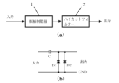
- FIG. 1A is a block diagram of a first embodiment of the present invention, and this embodiment has a high utility value for a device (such as a telephone) that does not require a high frequency signal.
- the amplitude suppressor according to the present embodiment includes an amplitude limiter 1 that inputs an audio signal, and a high-cut filter 2 that is connected to the output side thereof and outputs an audio signal after amplitude limitation.
- the amplitude limiter 1 is an amplitude limiter equivalent to that used in FIG. 10 of Japanese Patent No. 4976012 and a part of JP2011 − 1666652.
- an amplitude limiter hereinafter referred to as a bias shift type amplitude limiter
- the circuit is as shown in FIG.
- the DC potential of the cathode of the diode D1 or the anode of the diode D2 is 0 V, which is the same as GND.
- an amplitude signal larger than the forward voltage of the diode D1 or the diode D2 is input to the input, a current flows through the diode D1 or D2 and the capacitor C, the output signal amplitude is limited, and the capacitor C is charged. .
- This charging generates a voltage across the capacitor C.
- This voltage becomes the bias voltage of the output side circuit. That is, the amplitude is limited by changing the bias voltage of the output circuit by a large input signal. In this amplitude limiting method, information loss in a portion exceeding the limited amplitude is small, but distortion signals that deteriorate the reproduced sound quality are often generated.
- the high cut filter 2 removes high frequency components from the output signal of the amplitude limiter 1. Therefore, if a signal having a frequency higher than 4 KHz is deleted by the high cut filter 2, the output signal of the high cut filter 2 does not include a signal that significantly deteriorates the reproduction sound quality (discomfort to the ear in the sound distortion).
- the main cause is a frequency component higher than about 4 KHz). However, the frequency component lower than 4 kHz of the input signal is output as it is. Therefore, it is practical although it is simple for a device that does not require a signal of 4 kHz or higher.
- a slice type amplitude limiter that does not affect the sound quality is provided in the previous stage of this circuit, the generation of unpleasant sound signals generated by the bias shift type amplitude limiter can be reduced. That is, when a signal including a signal having a large variation in amplitude value is subjected to bias shift type amplitude limitation, a large signal causing unpleasant noise is randomly generated and is difficult to be removed by a high-cut filter in the next stage because it is random. However, when a signal whose level of a large signal is aligned by the slice type amplitude limit is subjected to the bias shift type amplitude limit, the bias shift is performed in the opposite direction by the same amount. Is done.
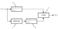
- FIG. 2 is a block diagram of the second embodiment of the present invention, which is highly useful when it is desired to obtain as much reproduced sound as possible with an acoustic system using a small output amplifier and small speakers.
- FIG. 1 is not suitable for a device that requires a high frequency signal such as for music, but in this embodiment, a high frequency signal is not deleted, so that a good frequency characteristic can be obtained even for music.
- the low cut filter 3 extracts only a high frequency signal from the input signal.
- the high frequency signal is added by the adder 4 with the low frequency signal generated by the amplitude limiter 5 and the high cut filter 6.
- the output signal of the low cut filter 3 does not include a signal that deteriorates the reproduction sound quality. Further, the output of the high cut filter 6 does not include a signal that significantly deteriorates the reproduction sound quality. Accordingly, the output signal of the adder 4 obtained by adding these two signals does not include a signal that greatly deteriorates the reproduction sound quality.
- the high frequency signal amplitude of the output of the adder 4 is not limited, when a very strong amplitude limitation is performed by the amplitude limiter 5 and the high cut filter 6 of the low frequency circuit, the high frequency signal amplitude is higher than the low frequency signal amplitude.
- the signal amplitude of the area becomes relatively large.
- the amplitude of the high frequency signal is small. Thus, if used for less severe amplitude limiting, this configuration with no high frequency signal amplitude limiting will not cause much problems.
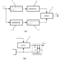
- FIG. 3A is a block diagram of the third embodiment of the present invention, which has high utility value for an audio device such as a hearing aid or a recording device that mainly reproduces sound using earphones or headphones.
- an amplitude limiter 8 is added after the low-cut filter 7 constituting the high-frequency circuit of the second embodiment.
- a high-frequency large-amplitude input signal appears as it is in the output. Disadvantages are eliminated.
- the amplitude limiter 8 limits the amplitude of the output signal (high frequency signal) of the low cut filter 7, an excessive amplitude signal does not appear at the output of the adder 9.
- the amplitude limiter 8 can obtain a better result with a general amplitude limiter (slice type) than with a bias shift type. The reason for this is that even if information exceeding the limit value is lost in a high-frequency signal, the effect on the playback sound is less, and the slice-type amplitude limiter is worse than the bias-shift type amplitude limiter. This is because less distortion signal is generated.
- the reason why the high frequency signal is processed separately from the low frequency signal is that when the high frequency signal is processed by the same method as the low frequency signal, distortion that causes unpleasant noise is often generated.
- the slice-type amplitude limiter 8 can be provided after the adder 9.
- the amplitude limit value should be smaller as the signal frequency is higher. In order to obtain a signal having such characteristics, it is effective to input a signal in which the high frequency is emphasized and attenuate the high frequency of the output signal.
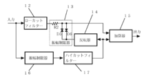
- FIG. 4 is a block diagram (partially circuit diagram) of the fourth embodiment of the present invention. Similar to the third embodiment, it is applied to an audio device such as a hearing aid or a recorder that reproduces sound mainly by earphones or headphones. High utility value.
- an inverter 14 that takes in and inverts an output signal from the high-cut filter 17 of the low-frequency circuit and supplies it to the amplitude limit reference potential circuit of the amplitude limiter 13 of the high-frequency circuit is added to the third embodiment. It is a configuration. That is, in the present embodiment, the output of the high cut filter 17 is branched to the adder 15 and the inverter 14, and the output from the inverter 14 is used as a reference for the parallel diodes D 5 and D 6 constituting the amplitude limiter 13. Connect to the voltage application side.
- the amplitude limiter 13 uses the amplitude limit of the high frequency band signal output from the low cut filter 12 as a reference and the inverted signal of the low frequency band signal that has been output from the high cut filter 17 as a reference. Limit the amplitude.
- the adder 15 adds the high frequency band signal whose amplitude is limited by the amplitude limiter 13 and the low frequency band signal from the high cut filter 17 and outputs the result.
- the output signal amplitude value of the adder 9 is the output amplitude value of the high cut filter 11 + the output amplitude value of the amplitude limiter 8. That is, if the maximum output amplitude of the high cut filter 11 and the maximum output amplitude of the amplitude limiter 8 are the same, the maximum output amplitude of the adder 9 is twice the maximum output amplitude of the high cut filter 11 or the waveform is deformed due to the amplitude limitation. A little bigger. However, considering the purpose of amplitude limitation, it is preferable that the maximum amplitude value of the adder 9 does not always exceed the maximum amplitude of the high cut filter 11.
- the inverter 14 of FIG. 4 is provided for this purpose.
- the maximum output amplitude value of the adder 15 does not exceed the maximum amplitude output value of the high cut filter 17. Therefore, the output signal having this configuration can obtain a large reproduced sound even when the maximum amplitude is smaller than that in FIG. This is also preferable as an excessive sound suppression characteristic.
- the maximum output amplitude in the case of FIG. 3 is “maximum output amplitude of the amplitude limiter 8 + maximum output amplitude of the high cut filter 11”. However, since the maximum output amplitude in FIG.
- the maximum output amplitude of the amplitude limiter 13 is dynamically controlled so that the maximum amplitude of the adder 15 does not exceed the maximum amplitude value of the high cut filter 17.
- FIG. 5 is a block diagram of a fifth embodiment of the present invention, which is highly useful for audio equipment that reproduces sound using earphones or headphones, particularly for hearing aids, as in the third and fourth embodiments.
- This embodiment is a modification of FIG. 3, and the amplitude limiter 10 of FIG. 3 is replaced with a low-frequency attenuator 21.
- the configuration of FIG. 3 is superior in terms of the amplitude limiting effect, but FIG. 5 is superior in terms of sound distortion.
- the amplitude of a sound wave is larger as the frequency is lower, and conversely, it is smaller when the frequency is higher, and the difference is very large. Therefore, if the low frequency range is attenuated within a range where the sound quality is not adversely affected, a considerable amplitude suppression effect can be obtained.
- the low range is attenuated, the sound reproduction by speaker radiation causes shortage of the low range, but a preferable result is obtained when the sound is reproduced close to the eardrum like an earphone or a headphone. Further, insufficient gain at the high frequency has an adverse effect on the sensitivity characteristics of the ear, but there is little problem because such harm does not occur at the low frequency.
- the microphone may have the function of the low-frequency attenuator 21 (many bidirectional microphones have low low-frequency sensitivity).
- FIG. 6 is a block diagram (partial circuit diagram) of the sixth embodiment of the present invention.
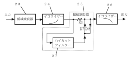
- the circuit configuration is different from that of FIG. 5, but the results are the same. That is, an equalizer 24 for high frequency emphasis is connected to the output side of the low frequency attenuator 23, an amplitude limiter 25 is connected to the output side of the equalizer 24, and the output from the amplitude limiter 25 is for high frequency attenuation. Is output to the outside via the equalizer 26.
- the amplitude limiter 25 includes forward and reverse diodes D5 and D6 connected in parallel to the subsequent stage of the resistor R3, and a high cut filter 27 connected in parallel to the resistor R3 and the diodes D5 and D6.
- the input side of the high cut filter 27 is connected to the output side of the high frequency emphasis equalizer 24, and the output side of the high cut filter 27 is connected to the reference voltage application side of the diodes D5 and D6.
- the low-frequency attenuator 23 of this embodiment obtains a low-frequency amplitude suppression effect by performing low-frequency attenuation of the input signal.
- the output signal of the low-frequency attenuator 23 is input to the equalizer 24, and the equalizer 24 outputs a signal in which the high frequency is emphasized.
- the amplitude limiter 25 limits the amplitude of the high frequency signal.
- the high cut filter 27 in the amplitude limiter 25 outputs a signal obtained by cutting the high frequency range of the input signal, and this output signal becomes the amplitude limit reference potential of the amplitude limiter 25. That is, the amplitude is limited so that a difference greater than the forward voltage of the diode D5 or D6 is not output compared to the output potential of the high cut filter 27. In this way, the amplitude limiter 25 limits the amplitude only to the high frequency component signal.
- the output signal of the amplitude limiter 25 is output through the equalizer 26. That is, after the high frequency emphasized signal by the equalizer 24 is amplitude limited by the amplitude limiter 25, the high frequency is attenuated by the equalizer 26, so that the output of the equalizer 26 is limited in amplitude to a smaller level as the frequency increases. Signal is output.
- the circuit configuration can be simplified if the low-frequency attenuation characteristic of the low-frequency attenuator 23 is a microphone and the high-frequency attenuation characteristic of the equalizer 26 is an earphone or headphones.
- FIG. 7 is a block diagram of the seventh embodiment of the present invention, which is highly useful in small hearing aids.
- a pseudo environmental sound generator 28 and an adder 29 are added to FIG.
- the simulated environmental sound generator 28 electrically generates an artificial environmental sound signal or outputs an environmental sound signal recorded in another environment.
- the output signals of the simulated environmental sound generator 28 and the high cut filter G31 are added by an adder 29 and output.
- Small hearing aids are usually close to microphones and earphones, and howling is likely to occur. And since howling is likely to occur at frequencies higher than low frequencies, small hearing aids often do not increase the gain at high frequencies, which causes unpleasant sound.
- the environmental sound is added by the pseudo environmental sound generator 28 without increasing the high frequency gain, howling does not easily occur and a comfortable sound without a feeling of blockage or pressure can be obtained. . If the output level of the simulated environmental sound generator 28 is proportional to the ambient environmental noise level, the simulated environmental sound generator 28 can automatically output a signal of an appropriate level according to the environment.
- FIG. 8 is a block diagram of an eighth embodiment of the present invention, which is highly useful in small hearing aids as in FIG.
- the amplitude limiter 30 in FIG. 7 is replaced with a low-frequency attenuator 34.
- the amplitude suppression characteristic is inferior to that of FIG. 7, it is possible to obtain a reproduced sound with less distortion than the configuration of FIG. Even in a normal acoustic device using earphones or headphones, noise that can be heard can be reduced by adding simulated environmental sound to the reproduced sound.
- FIG. 9 is a block diagram of the ninth embodiment of the present invention.
- the intelligibility of the sound to be heard can be set optimally.
- a variable gain amplifier 37 is added to FIG. 2, and the high frequency signal level can be adjusted by the variable gain amplifier 37. Since the sensitivity of the ear changes with the strength of the high frequency sound, changing the level of the high frequency sound can change the way of hearing.
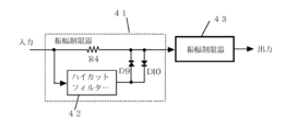
- FIG. 10 is a block diagram of a circuit in which a high frequency component, which is a drawback of the configuration of FIG. 1, is eliminated with a relatively simple configuration.
- two types of amplitude limiters 41 and 43 are used.
- the first amplitude limiter 41 incorporates a high cut filter 42 in the reference voltage application portion, similar to that used in the sixth embodiment of FIG. 6, and limits the amplitude in the high frequency region.
- the second amplitude limiter 42 limits the amplitude in the low frequency region.
- the high-cut filter 2 removes high-frequency distortion components that cause unpleasant noise, but the high-cut filter 2 also removes high-frequency components contained in the original signal. Therefore, a high frequency component is lost in the output signal.
- the output circuit will contain the high frequency signal of the original signal sufficiently, and the high frequency distortion component. Fewer signals are extracted.
- the input signal is input to the amplitude limiter 41, and a low frequency region signal from the high cut filter 42 is used as an operation reference voltage for the diodes D9 and D10, so that high frequency slice type amplitude limitation is performed (this operation is performed). This is the same as the case of the amplitude limiter in FIG. 6).
- the output signal of the amplitude limiter 41 is input to the second amplitude limiter 43, where the bias shift type amplitude limitation of the low frequency signal is performed. At this time, since the level of the high frequency signal input to the amplitude limiter 43 is small, a signal having a high frequency and a small distortion component is obtained in the output circuit of the amplitude limiter 43.
- FIG. 10 the characteristics are slightly sacrificed, but an output signal that is not so different from that in FIG. 4 can be obtained with a simple circuit configuration. That is, when a high frequency signal is subjected to the bias shift type amplitude limitation, a large amount of distortion signals that cause unpleasant reproduced sound are generated. Therefore, in FIG. 10, before the signal is input to the bias shift type amplitude limiter, the high frequency signal is subjected to the slice type amplitude limitation. As a result, the high frequency signal is not subjected to the bias shift type amplitude limitation. The original distortion signal is not produced much. Even with a low frequency signal, a certain amount of high frequency distortion signal is generated due to the bias shift type amplitude limitation, so that the sound quality is deteriorated.
- this circuit is well worth it because its distortion is small. Further, if the high frequency component emphasis and the high frequency component attenuation of the output signal are performed to limit the smaller amplitude as the frequency signal is higher, the high frequency distortion component in the output signal is further reduced.
- the low-cut filter 13 includes an amplitude limiter 14, an inverter 15, an adder 16, an amplitude limiter 17, a high-cut filter 18, a low-cut filter 19, an amplitude limiter 20, an adder 21, a low-frequency attenuator 22, and a high-cut filter 23.
- the band attenuator 24 is an equalizer 25, an amplitude limiter 26, an equalizer 27 is a high cut filter 28, a pseudo environmental sound generator 29 is an adder 30, an amplitude limiter 31 is a high cut filter 32, and a pseudo environmental sound generator 33 is an adder 34.
- the low frequency attenuator 35 is the high cut filter 36 is the low cut.
- the filter 37 is a variable gain amplifier 38, the adder 39, the amplitude limiter 40, the high cut filter 41, the amplitude limiter 42, the high cut filter 43, and the amplitude limiter C are capacitors R1, R2, R3, R4 are resistors D1, D2, D3, D4, D5, D6, D7, D8, D9, D10 are diodes
Abstract
従来の音響システムによって、マイクロホンで集音された音信号を増幅してイヤホンやヘッドホンによって耳に加えると、過大音や環境雑音が不快であり言葉の了解度も悪いので、これを改善する。また音響機器の小形高性能化を計る。入力信号振幅が規定レベルを越えるとバイアス電位が振幅の変化と反対方向にシフトされる振幅制限器1と前記振幅制限器1からの出力信号の高い周波数成分が削除又は減衰されて出力されるハイカットフィルター2を備える。
Description
この発明は音信号を、イヤホンやヘッドホンによる音再生に適した信号に変換するための音声信号振幅抑圧装置に関する。つまり、耳及び再生機器への負担が少なく、了解度が高い再生音を得ることが出来る形に音声信号を加工する技術に係る。
マイクロホンで収音された音をそのままイヤホンやヘッドホンを用いる再生装置で聞くと、大振幅信号や雑音が大変大きく聞こえたり、言葉の再生では明瞭度が低い、閉塞感や圧迫感を伴う、等の問題があった。そのため、大振幅の問題には再生音品質の低下が少ない振幅制限装置や振幅抑圧装置が当発明者によって考案された(特許文献1~3)。それらは動作に伴って聴感を不快にさせる歪み信号(再生音の歪みの中で聴感を不快にさせる主因は約4KHz以上の周波数成分である)が発生するので、その歪み信号を除く或いは軽減する機能を内包している。
しかし、その方式には必要な信号を残しながら有害な信号を排除する能力に限界があったし、高い周波数帯域で良好な周波数特性を確保出来難くい問題もあった。また、雑音、明瞭度、閉塞感、圧迫感等の問題にも十分な効果が無かった。更に、高い周波数信号を必要としない機器用としては無駄な部分があった。
従来、イヤホンやヘッドホンによる音再生での、雑音、閉塞感、圧迫感、言葉の明瞭度が低い等の原因は不明だった。そのため適切な解決方法が無く、補聴器や録音機などにおいて大きな問題だった(補聴器には雑音を消去する機能を持った製品もあるが、消去によって解決する問題ではない)。
本発明者は補聴器を開発する過程において次の発見をした。それは、耳の感度は高い周波数の環境音(一般的に環境雑音と考えられている高い周波数成分)によって変化し、その環境音が多い或いは強いと耳の感度は低くなり、弱いと高くなることである。そのため、この環境音だけが消去或いは弱められた音を耳に加えると低域周波数音が不自然に大きく聞こえて閉塞感や圧迫感の原因となる。
また、高い周波数の環境音は開放感や臨場感に大きな影響を与える。骨伝導ヘッドホンの音は耳栓を併用すると聞こえ易いことが知られているが、これは耳栓によって高い周波数の環境音が遮断され耳の感度が高くなるのが一因である。更に、周囲の音を聞こえ難くする機能を持ったイヤホンやヘッドホン(一般的にはノイズキャンセルイヤホンと呼ばれている)が普及しているが、その機能を働かせると使用者は閉塞を感じることがあるのも環境音、特に高い周波数の環境音が聞こえないからである。
マイクロホンで収音された言葉をイヤホンやヘッドホンを用い良好な周波数特性で再生しながら、音量を変化させると了解度が変化する。そして音量を大から小へ変化させていくと言葉の音量感はそれほど変わらないのに環境音は急に小さく感じる点があり、この付近で了解度は最も高くなる。耳が騒音の中でも言葉を聴き分ける優れた能力を持っていることとこの現象は関係が深いと考えられる。
テレビやラジオ放送、或いは市販音楽ソフト等の音信号には振幅制限が施されている。目的は主に音響機器の能力不足による問題を回避するためであるが、この振幅制限は低域周波数においてイヤホンやヘッドホン再生のためにも好ましい結果をもたらしている。
しかし、高域周波数においてはイヤホンやヘッドホン再生のために効果的な振幅制限は行われていない。そのため、これらの信号をフラットな周波数特性のイヤホンやヘッドホンを使用して聞くと高い音が強過ぎに聞こえる。(健康な人の耳は、入ってくる音に適切な振幅制限を行っていると考えられるが、その仕組みや、イヤホンやヘッドホンを用いるとこの振幅制限機能が何故働かないかは不明である。)
しかし、高域周波数においてはイヤホンやヘッドホン再生のために効果的な振幅制限は行われていない。そのため、これらの信号をフラットな周波数特性のイヤホンやヘッドホンを使用して聞くと高い音が強過ぎに聞こえる。(健康な人の耳は、入ってくる音に適切な振幅制限を行っていると考えられるが、その仕組みや、イヤホンやヘッドホンを用いるとこの振幅制限機能が何故働かないかは不明である。)
イヤホンやヘッドホンによる再生音が自然な音質で聞こえるためには、音の全周波数帯に適切な振幅制限が施されていることと、振幅制限値内の信号に対する利得特性がどの周波数も均一であることが重要である。しかしイヤホンやヘッドホンを用いる従来システムでは利得特性が平坦でないがゆえに、高い周波数音も適度な音量で聞こえる。つまり、通常のイヤホンやヘッドホンは高域感度が低く造られているので(これはイヤホン製造の容易さのためにも好都合ではある)、高い音も強過ぎないで聞こえる。しかし、その再生音の高域周波数ゲインは不足であり、環境音は正しく聞こえない。
その結果イヤホンやヘッドホンによる再生音は不快感を伴い易い。「補聴器を使うと雑音が不快だし遠い音源の言葉を聞き取れない」、「録音された音を再生しても遠い音源の言葉が聞き取れない」などはイヤホンやヘッドホンの高い周波数のゲインが低いことに起因する。つまり、イヤホンやヘッドホン再生に適した振幅制限とどの周波数も均一なゲイン特性の再生が行われるならこの問題は起こらない。
スピーカーによる音再生では振幅制限が行われなくても問題は無い筈なのに、イヤホンの場合と同様に遠い音源の言葉は聞き取り難い。原因はスピーカー輻射による再生音場と収録時の音場は著しく異なるからだと考えられる。これに対しイヤホンやヘッドホンによる再生では収録時に近い音波を耳に加えることが出来るので、スピーカーによる音再生より優れている。しかし前記の理由で問題が多い。
イヤホンやヘッドホンで音が再生される従来音響システムでは、マイクロホンによって収音された信号をそのまま増幅して耳に入れると過大音や環境雑音が不快であると共に言葉の了解度が低い欠点があるのでこれを改善する。また、機器の能力を高効率で利用出来る音再生信号をつくる。
本発明は、低域周波数帯域は情報消失が少ない方法で振幅制限又は振幅抑圧を行い、高い周波数はそのままかスライス型振幅制限、或いはカット、もしくは疑似音の付加を行うことを特徴とする。具体的には、次のような手段を採用する。
本発明において、振幅抑圧装置とは、振幅を一定の範囲に制限して範囲外の振幅をカットする装置と、範囲外の信号はカットされることなく、大きな値の入力信号が減衰されて出力される装置の双方を包含する。
本発明によれば、イヤホンやヘッドホンが用いられる音響機器において、耳への負担が少なく、自然な音質で高い了解度の再生音が得られるので、難聴用機器や録音機の性能を大きく向上させることが出来る。また、小出力の音響機器でも比較的大きな音量が得られるので、音響機器の小型高性能化に大きな効果がある。
以下、本発明の実施形態について具体的に説明する。
[1.第1実施形態]
図1(a)は本発明の第1実施形態のブロック図であり、本実施形態は、高い周波数信号は不要な機器(例えば電話機など)への利用価値が高い。本実施形態の振幅抑圧装置は、音声信号を入力する振幅制限器1と、その出力側に接続されて振幅制限後の音声信号を出力するハイカットフィルター2とから構成されている。
図1(a)は本発明の第1実施形態のブロック図であり、本実施形態は、高い周波数信号は不要な機器(例えば電話機など)への利用価値が高い。本実施形態の振幅抑圧装置は、音声信号を入力する振幅制限器1と、その出力側に接続されて振幅制限後の音声信号を出力するハイカットフィルター2とから構成されている。
振幅制限器1は特許第4976012号の図10や特開2011−166652の一部に使用されているのと同等の振幅制限器である。すなわち、振幅が一定レベルを越えるとその越える振幅値分、動作基準電位、つまりバイアス電位が反対方向にシフトされることで振幅制限が行われる振幅制限器(以下、バイアスシフト型振幅制限器と記す)であり、原理的には図1(b)のような回路である。
図1(b)において、入力信号が無い初期状態では、ダイオードD1のカソード或いはダイオードD2のアノードの直流電位はGNDと同じ0Vである。しかし、入力にダイオードD1或いはダイオードD2の順方向電圧より大きい振幅信号が入力されると、ダイオードD1又はD2及びコンデンサCに電流が流れて、出力信号振幅が制限されると共にコンデンサCは充電される。この充電によってコンデンサC両端に電圧が発生する。そして、この電圧は出力側回路のバイアス電圧となる。つまり、大きな入力信号によって出力回路のバイアス電圧が変化して振幅制限が行われる。この振幅制限方式では制限振幅を越える部分の情報消失が少ない反面、再生音品質を悪化させる歪み信号の発生は多い。
ハイカットフィルター2は振幅制限器1の出力信号から高い周波数成分を削除する。だからもし、ハイカットフィルター2によって4KHzより高い周波数の信号が削除されるなら、ハイカットフィルター2の出力信号には再生音品質を著しく劣化させる信号は含まれない(音歪みの中で耳に不快を与える主因は約4KHzより高い周波数成分である)。しかし入力信号の4KHzより低い周波数成分はそのまま出力される。従って4KHz以上の信号が不要な機器用として、簡単にも関わらず実用的である。
この回路の前段に、音質にあまり影響を与えない程度のスライス型振幅制限器を設けると、バイアスシフト型振幅制限器で発生する不快音信号の発生を小さく出来る。すなわち、振幅値の変動が大きな信号を含む信号がバイアスシフト形振幅制限を受けると不快音の原因となる大きな信号がランダムに発生し、ランダムであるがゆえに次段のハイカットフィルターで除かれ難い。しかし、スライス形振幅制限によって大きな信号のレベルが揃えられた信号がバイアスシフト形振幅制限を受けた場合、バイアスシフトは同じだけ互いに反対方向に行われるので、次段のハイカットフィルターで効果的に消去される。
動作と結果は少し異なるが、振幅制限器1とハイカットフィルター2は接続を逆にしても、つまりハイカットフィルター2の出力に振幅制限器1を接続しても、それ程遜色の無い効果が得られる。
[2.第2実施形態]
図2は本発明の第2実施形態のブロック図であり、小出力アンプと小型スピーカーによる音響システムで出来るだけ大きな再生音を得たい場合に利用価値が高い。
図2は本発明の第2実施形態のブロック図であり、小出力アンプと小型スピーカーによる音響システムで出来るだけ大きな再生音を得たい場合に利用価値が高い。
これは図1にローカットフィルター3と加算器4が加えられた構成である。すなわち、入力信号をローカットフィルター3と振幅制限器5とにそれぞれ供給し、振幅制限器5からの出力側にハイカットフィルター6を接続して、ローカットフィルター3の出力とハイカットフィルター6の出力を加算器4で加算した後、出力するものである。
図1の構成は音楽用など高い周波数信号が必要な機器に適さないが、この本実施形態では高い周波数信号が削除されないので、音楽用としても良好な周波数特性が得られる。
このような構成を有する本実施形態では、ローカットフィルター3は入力信号の中から高い周波数信号だけを取り出す。そしてこの高い周波数信号は、振幅制限器5とハイカットフィルター6によってつくり出された低域信号と、加算器4で加算される。
ローカットフィルター3は音を歪ませる要素が無いので、ローカットフィルター3の出力信号に再生音品質を劣化させる信号は含まれない。また、ハイカットフィルター6の出力にも再生音品質を著しく劣化させる信号は含まれない。従ってこの二つの信号が加算された加算器4の出力信号に再生音品質を大きく劣化させる信号は含まれない。
この構成では、加算器4出力の高い周波数信号振幅は制限されていないので、低域回路の振幅制限器5とハイカットフィルター6で大変強い振幅制限が行われる場合は、低域信号振幅に対し高域信号振幅が相対的に大きくなる欠点がある。しかし平均的な音信号では高い周波数信号の振幅は小さい。従って、それほど強くない振幅制限に用いられるなら、高い周波数信号の振幅制限が行われないこの構成でもあまり問題は起こらない。
[3.第3実施形態]
図3(a)は本発明の第3実施形態のブロック図であり、補聴器や録音機等、主にイヤホンやヘッドホンで音を再生する音響機器への利用価値が高い。
図3(a)は本発明の第3実施形態のブロック図であり、補聴器や録音機等、主にイヤホンやヘッドホンで音を再生する音響機器への利用価値が高い。
これは第2実施形態の高域回路を構成するローカットフィルター7の後段に、振幅制限器8が加えられたものであり、第2実施形態において、高い周波数の大振幅入力信号がそのまま出力に現れる欠点が除かれている。
振幅制限器8はローカットフィルター7の出力信号(高域周波数信号)を振幅制限するので、加算器9の出力に過大な振幅信号は現れない。尚、振幅制限器8はバイアスシフト型よりも一般的な振幅制限器(スライス型)の方が良い結果が得られる。理由は、高い周波数信号では制限値を越える部分の情報が消失しても再生音への影響が少ないことと、スライス型振幅制限器の方がバイアスシフト型振幅制限器よりも再生音品質を悪化させる歪み信号の発生が少ないからである。なお、高い周波数信号の処理を低域信号とは別に行う理由は、高域信号を低域信号と同じ手法で処理すると、不快音の元になる歪みの発生が多いからである。
ローカットフィルター7とハイカットフィルター11の遮断特性はそれほど急斜でなくても問題は少ない。何故ならバイアスシフト型振幅制限により発生する歪み信号の不快度は周波数の高さに比例して次第に強くなるので、振幅制限方式もなだらかに変化すれば十分だからである。
図3の(b)のように、スライス型の振幅制限器8は加算器9の後に設けることも可能である。また、この振幅制限値は信号の周波数が高い程小さくすべきである。そのような特性の信号を得るには、高域周波数が強調された信号を入力し、出力された信号の高域を減衰させるのが効果的である。
[4.第4実施形態]
図4は本発明の第4実施形態のブロック図(一部回路図)であり、第3実施形態と同様に、補聴器や録音機等、主にイヤホンやヘッドホンで音を再生する音響機器への利用価値が高い。
図4は本発明の第4実施形態のブロック図(一部回路図)であり、第3実施形態と同様に、補聴器や録音機等、主にイヤホンやヘッドホンで音を再生する音響機器への利用価値が高い。
本実施形態は、低域回路のハイカットフィルター17からの出力信号を取り込んで反転し、高域回路の振幅制限器13の振幅制限基準電位回路に供給する反転器14が第3実施形態に加えられた構成である。すなわち、本実施形態では、ハイカットフィルター17の出力を、加算器15と反転器14とに分岐して、反転器14からの出力を、振幅制限器13を構成する並列なダイオードD5,D6の基準電圧印加側に接続する。このようにすると、振幅制限器13は、ローカットフィルター12から出力された高周波帯域の信号の振幅制限を、ハイカットフィルター17から出力された振幅制限済みの低周波帯域の信号の反転信号を基準として、振幅制限を行う。
その結果、ハイカットフィルター17からの低周波帯域の信号の振幅がプラス側に大きい場合には、ローカットフィルター12からの高周波帯域の信号の制限振幅はプラス側が小さく制限される。反対にハイカットフィルター17からの低周波帯域の信号の振幅がマイナス側に大きい場合には、マイナス側が小さく制限される。(P-P値は変わらない。)その後、加算器15によって、振幅制限器13によって振幅制限された高周波帯域の信号と、ハイカットフィルター17からの低周波帯域の信号を加算して、出力する。
図3の構成において、加算器9の出力信号振幅値はハイカットフィルター11の出力振幅値+振幅制限器8の出力振幅値となる。つまり、ハイカットフィルター11の最大出力振幅と振幅制限器8の最大出力振幅が同じとすると、加算器9の最大出力振幅はハイカットフィルター11最大出力振幅の2倍か、振幅制限に伴う波形の変形でもう少し大きい。しかし、振幅制限の目的を考慮すれば、加算器9の最大振幅値はいつでもハイカットフィルター11の最大振幅を越えない方が好ましい。図4の反転器14はそのために設けられている。
つまり、ハイカットフィルター17の出力振幅値が変化すると、その変化値と同じだけ振幅制限器13の振幅制限値は反対方向に変化する。従って加算器15の最大出力振幅値はハイカットフィルター17の最大振幅出力値以上にはならない。そのため、この構成の出力信号は、図3に比べ最大振幅が小さくても大きな再生音を得ることができる。これは過大音抑止特性としても好ましい。図3の場合の出力最大振幅は「振幅制限器8の最大出力振幅+ハイカットフィルター11の最大出力振幅」になる。しかし、図4の最大出力振幅はハイカットフィルター17の最大出力振幅を超えることがないため、再生音質に大きな違いをつくらないで図3より最大出力振幅を小さく制限出来る。つまり加算器15の最大振幅がハイカットフィルター17の最大振幅値を超えない様に振幅制限器13の制限振幅がダイナミックにコントロールされる。
[5.第5実施形態]
図5は本発明の第5実施形態のブロック図であり、第3実施形態や第4実施形態と同様に、イヤホンやヘッドホンで音を再生する音響機器、特に補聴器類への利用価値が高い。
図5は本発明の第5実施形態のブロック図であり、第3実施形態や第4実施形態と同様に、イヤホンやヘッドホンで音を再生する音響機器、特に補聴器類への利用価値が高い。
本実施形態は図3の変形であり、図3の振幅制限器10が低域減衰器21に置き換えられている。振幅制限効果の点では図3の構成の方が優れるが、音歪みの点では図5の方が優れる。
一般的に音波の振幅は周波数が低い程大きく、反対に周波数が高いと小さくて、その差は非常に大きい。そのため音質に悪影響がない範囲で低域を減衰させればかなりの振幅抑圧効果が得られる。低域を減衰させると、スピーカー輻射による音再生では低域不足を
起こすが、イヤホンやヘッドホンのように鼓膜の至近で音が再生される場合はむしろ好ましい結果が得られる。また高域周波数のゲイン不足は耳の感度特性等に悪影響を及ぼす
が、低域周波数ではそのような害は起こらないので問題は少ない。
起こすが、イヤホンやヘッドホンのように鼓膜の至近で音が再生される場合はむしろ好ましい結果が得られる。また高域周波数のゲイン不足は耳の感度特性等に悪影響を及ぼす
が、低域周波数ではそのような害は起こらないので問題は少ない。
補聴器類のようにマイクロホンと一体で動作する機器の場合は、低域減衰器21の機能をマイクロホンに持たせても良い(双指向性マイクロホンには低域の感度が低いものが多い)。
[6.第6実施形態]
図6は本発明の第6実施形態のブロック図(一部回路図)であり、図5とは回路構成が異なるが結果は同様である。すなわち、低域減衰器23の出力側に高域強調用のイコライザー24を接続し、このイコライザー24の出力側に振幅制限器25を接続し、振幅制限器25からの出力は、高域減衰用のイコライザー26を経由して外部に出力する。振幅制限器25は、抵抗R3の後段に並列接続された正逆方向のダイオードD5,D6と、これら抵抗R3及びダイオードD5,D6に対して並列接続されたハイカットフィルター27とから構成されている。ハイカットフィルター27の入力側は高域強調用イコライザー24の出力側に、ハイカットフィルター27の出力側はダイオードD5,D6の基準電圧印加側に接続されている。
図6は本発明の第6実施形態のブロック図(一部回路図)であり、図5とは回路構成が異なるが結果は同様である。すなわち、低域減衰器23の出力側に高域強調用のイコライザー24を接続し、このイコライザー24の出力側に振幅制限器25を接続し、振幅制限器25からの出力は、高域減衰用のイコライザー26を経由して外部に出力する。振幅制限器25は、抵抗R3の後段に並列接続された正逆方向のダイオードD5,D6と、これら抵抗R3及びダイオードD5,D6に対して並列接続されたハイカットフィルター27とから構成されている。ハイカットフィルター27の入力側は高域強調用イコライザー24の出力側に、ハイカットフィルター27の出力側はダイオードD5,D6の基準電圧印加側に接続されている。
本実施形態の低域減衰器23は入力信号の低域減衰を行うことで低域の振幅抑圧効果を得ている。低域減衰器23の出力信号はイコライザー24に入力されて、イコライザー24からは高域が強調された信号が出力される。
振幅制限器25では高い周波数信号の振幅制限が行われる。振幅制限器25内のハイカットフィルター27は入力された信号の高域がカットされた信号を出力し、この出力信号は振幅制限器25の振幅制限基準電位となる。つまり、ハイカットフィルター27の出力電位に比べダイオードD5又はD6の順方向電圧以上の差が出力されないように振幅制限が行われる。このようにして振幅制限器25では高域成分信号にだけ振幅制限が行われる。
振幅制限器25の出力信号はイコライザー26を経て出力される。つまりイコライザー24で高域強調された信号が振幅制限器25で振幅制限された後、イコライザー26で高域が減衰されることで、イコライザー26の出力には周波数が高いほど小レベルに振幅制限された信号が出力される。低域減衰器23の低域減衰特性をマイクロホンで、イコライザー26の高域減衰特性をイヤホン或いはヘッドホンで行えば回路構成を簡単に出来る。
[7.第7実施形態]
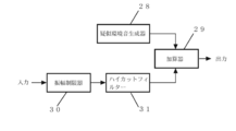
図7は本発明の第7実施形態のブロック図であり、小型補聴器類で利用価値が高い。本実施形態は図1に疑似環境音生成器28と加算器29が加えられた構成である。疑似環境音生成器28は電気的に人工環境音信号を生成するか、或いは別の環境で収録された環境音信号を出力する。疑似環境音生成器28とハイカットフィルターG31の出力信号は加算器29で加算されて出力される。
図7は本発明の第7実施形態のブロック図であり、小型補聴器類で利用価値が高い。本実施形態は図1に疑似環境音生成器28と加算器29が加えられた構成である。疑似環境音生成器28は電気的に人工環境音信号を生成するか、或いは別の環境で収録された環境音信号を出力する。疑似環境音生成器28とハイカットフィルターG31の出力信号は加算器29で加算されて出力される。
図1の構成によるイヤホンやヘッドホンによる音再生では高い音が欠落しているので閉塞感や圧迫感を感じることがあるが、この構成では、疑似環境音生成器28によって環境音信号が加えられるのでその欠点がない。
小型補聴器類はマイクロホンとイヤホンが近接しているのが普通であり、ハウリングが起き易い。そしてハウリングは低い周波数より高い周波数で起きやすいので小型補聴器類では高い周波数のゲインを高くしない場合が多く、これが不快な音の原因となっている。しかし、この方式では高い周波数のゲインを上げなくても疑似環境音生成器28によって環境音が加えられるので、ハウリングが起き難い上に、閉塞感や圧迫感のない快適な聞こえを得ることが出来る。尚、疑似環境音生成器28の出力レベルが周囲の環境雑音レベルの大きさに比例する仕組みにすれば、疑似環境音生成器28は自動で環境に応じた適正レベルの信号を出力出来る。
[8.第8実施形態]
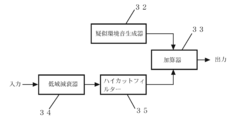
図8は本発明の第8実施形態のブロック図であり、図7同様小型補聴器類で利用価値が高い。本実施形態は、図7における振幅制限器30が低域減衰器34に置き替えられた構成である。振幅抑圧特性は図7より劣るが、図7の構成より歪みが少ない再生音を得ることが出来る。尚、イヤホンやヘッドホンが用いられる通常の音響装置でも、再生音に疑似環境音を加えれば聞こえるノイズを低減できる。
図8は本発明の第8実施形態のブロック図であり、図7同様小型補聴器類で利用価値が高い。本実施形態は、図7における振幅制限器30が低域減衰器34に置き替えられた構成である。振幅抑圧特性は図7より劣るが、図7の構成より歪みが少ない再生音を得ることが出来る。尚、イヤホンやヘッドホンが用いられる通常の音響装置でも、再生音に疑似環境音を加えれば聞こえるノイズを低減できる。
[9.第9実施形態]
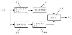
図9は本発明の第9実施形態のブロック図であり、補聴器類や録音機に適用すれば聞きたい音の了解度を最適に設定出来る。本実施形態は、図2に利得可変増幅器37が追加された構成であり、利得可変増幅器37によって高い周波数信号のレベルを調整出来る。耳の感度は高い周波数音の強さで変わるので高い周波数音のレベルを変えれば聞こえ方を変化させることができる。
図9は本発明の第9実施形態のブロック図であり、補聴器類や録音機に適用すれば聞きたい音の了解度を最適に設定出来る。本実施形態は、図2に利得可変増幅器37が追加された構成であり、利得可変増幅器37によって高い周波数信号のレベルを調整出来る。耳の感度は高い周波数音の強さで変わるので高い周波数音のレベルを変えれば聞こえ方を変化させることができる。
[10.第10実施形態]
図10は、図1構成の欠点である高い周波数成分が欠落するのを、比較的簡単な構成で除いた回路のブロック図である。本実施形態では、2種類の振幅制限器41,43を使用する。第1の振幅制限器41は、前記図6の第6実施形態に使用したものと同様に、基準電圧印加部分にハイカットフィルター42を組み込んだもので、高周波領域の振幅制限を行う。第2の振幅制限器42は、低周波領域の振幅制限を行う。
図10は、図1構成の欠点である高い周波数成分が欠落するのを、比較的簡単な構成で除いた回路のブロック図である。本実施形態では、2種類の振幅制限器41,43を使用する。第1の振幅制限器41は、前記図6の第6実施形態に使用したものと同様に、基準電圧印加部分にハイカットフィルター42を組み込んだもので、高周波領域の振幅制限を行う。第2の振幅制限器42は、低周波領域の振幅制限を行う。
図1の構成では、ハイカットフィルター2で不快音の原因となる高い周波数の歪み成分が除かれるが、ハイカットフィルター2では原信号に含まれる高い周波数成分も除かれる。そのため出力信号では高い周波数成分が欠落する。
図1の構成において発生する高い周波数の歪み成分は、原信号中の高い周波数信号がバイアスシフト型リミッターで振幅制限される時に多量に発生する。勿論低い周波数成分によっても発生するがそれは比較的少ない。従って、入力信号の高い周波数成分がスライス型リミッターでレベル制限された信号がバイアスシフト型リミッターに入力されるなら、出力回路には原信号の高域信号は十分含くまれ、高い周波数の歪み成分は少ない信号が取り出される。
入力信号は振幅制限器41に入力され、ハイカットフィルター42からの低周波領域の信号をダイオードD9,D10の動作基準電圧とすることで、高い周波数のスライス型振幅制限を行っている(この動作は図6における振幅制限器の場合と同じである)。振幅制限器41の出力信号は、第2の振幅制限器43に入力され、ここで低域信号のバイアスシフト型振幅制限が行われる。この時振幅制限器43に入力される高い周波数信号のレベルは小さいので、振幅制限器43出力回路には高い周波数の歪み成分の少ない信号が得られる。
この図10では、特性は少し犠牲になるが、簡単な回路構成で図4とあまり違わない出力信号が得られる。つまり高い周波数信号がバイアスシフト型振幅制限を受けると不快再生音の元になる歪み信号が多量に発生する。そこで、図10では、信号がバイアスシフト型振幅制限器に入力される前に、高い周波数信号にはスライス型振幅制限を施す結果、高い周波数信号はバイアスシフト型振幅制限を受けないので不快音の元になる歪み信号はあまりつくられない。低い周波数信号でもバイアスシフト型振幅制限によってある程度の高周波数歪み信号が発生するから、その分音質は悪くなる。しかし、その歪みは少ないのでこの回路は十分価値がある。また、高い周波数信号ほど小さい振幅制限を行うための、入力信号の高域周波数成分強調と出力信号の高域周波数成分減衰が行われるなら出力信号中の高い周波数の歪み成分は更に少なくなる。
本発明によれば、小型音響機器や難聴機器の高性能化に多大な効果がある。
1は振幅制限器
2はハイカットフィルター
3はローカットフィルター
4は加算器
5は振幅制限器
6はハイカットフィルター
7はローカットフィルター
8は振幅制限器
9は加算器
10は振幅制限器
11はハイカットフィルター
12はローカットフィルター
13は振幅制限器
14は反転器
15は加算器
16は振幅制限器
17はハイカットフィルター
18はローカットフィルター
19は振幅制限器
20は加算器
21は低域減衰器
22はハイカットフィルター
23は低域減衰器
24はイコライザー
25は振幅制限器
26はイコライザー
27はハイカットフィルター
28は疑似環境音生成器
29は加算器
30は振幅制限器
31はハイカットフィルター
32は疑似環境音生成器
33は加算器
34は低域減衰器
35はハイカットフィルター
36はローカットフィルター
37は利得可変増幅器
38は加算器
39は振幅制限器
40はハイカットフィルター
41は振幅制限器
42はハイカットフィルター
43は振幅制限器
Cはコンデンサ
R1、R2、R3、R4は抵抗器
D1、D2、D3、D4、D5、D6、D7、D8、D9、D10はダイオード
Claims (10)
- 入力信号振幅が規定レベルを越えるとバイアス電位が振幅の変化と反対方向にシフトされる振幅制限器と、前記振幅制限器からの出力信号の高い周波数成分が削除又は減衰されて出力されるハイカットフィルターを備えた音声信号振幅抑圧装置。
- 入力信号の比較的低い周波数成分の振幅が規定レベルを越えるとバイアス電位が振幅の変化と反対方向にシフトされることで振幅制限する振幅制限器を備えた音声信号振幅抑圧装置。
- 音声信号の低い周波数成分を減衰させるローカットフィルターと、前記ローカットフィルターの出力信号の高域成分をカット又は減衰するハイカットフィルターと、前記ローカットフィルターの出力信号がハイカットフィルターの出力電位を基準にして振幅制限される振幅制限器を備えた音声信号振幅抑圧装置。
- 入力信号から高域周波数成分を取り出すローカットフィルターと、その取り出された信号が出力信号に加算する加算器を備えた、請求項1の音声信号振幅抑圧装置。
- 入力信号の比較的低い周波数成分では振幅が規定レベルを越えるとバイアス電位が振幅の変化と反対方向にシフトされることで振幅制限される振幅制限器と、入力信号の比較的高い周波数成分では規定値を超える振幅部分が削除されることで振幅制限が行われる振幅制限器を備えた、音声信号振幅抑圧装置。
- 入力信号の低域周波数成分と高域周波数成分が減衰或いは削除された信号を取り出すローカットフィルター及びハイカットフィルターと、入力信号から取り出された高域周波数信号が振幅制限された信号を取り出す振幅制限器と、前記二つの出力信号が加算されて出力される加算器を備えた音声信号振幅抑圧装置。
- 音声信号の振幅制限値が他の音声信号の振幅値によってコントロールされる振幅制限器を備えた請求項5または請求項6の音声信号振幅抑圧装置。
- 疑似環境音信号の生成器と、その生成信号が出力信号に加算される加算器を備えた、請求項1の音声信号振幅抑圧装置。
- 入力信号の低域周波数成分と高域周波数成分が減衰或いは削除された信号を取り出すローカットフィルターとハイカットフィルターと、疑似環境音信号の生成器と、前記二つの機能の出力信号が加算されて出力される加算器を備えた音声信号振幅抑圧装置。
- 低域周波数成分と、高域周波数成分或いは疑似環境音信号の加算レベル比を変化させることができる手段を備えた請求項3から請求項9のいずれか1項に記載の音声信号振幅抑圧装置。
Priority Applications (3)
| Application Number | Priority Date | Filing Date | Title |
|---|---|---|---|
| EP14811383.0A EP3010146A4 (en) | 2013-06-11 | 2014-03-26 | Audio signal amplitude suppression device |
| SG11201510160SA SG11201510160SA (en) | 2013-06-11 | 2014-03-26 | Sound signal amplitude suppressing apparatus |
| US14/956,428 US10097929B2 (en) | 2013-06-11 | 2015-12-02 | Sound signal amplitude suppressing apparatus |
Applications Claiming Priority (4)
| Application Number | Priority Date | Filing Date | Title |
|---|---|---|---|
| JP2013134290 | 2013-06-11 | ||
| JP2013-134290 | 2013-06-11 | ||
| JP2013-189417 | 2013-09-12 | ||
| JP2013189417A JP6151613B2 (ja) | 2013-06-11 | 2013-09-12 | 音声信号振幅抑圧装置 |
Related Child Applications (1)
| Application Number | Title | Priority Date | Filing Date |
|---|---|---|---|
| US14/956,428 Continuation US10097929B2 (en) | 2013-06-11 | 2015-12-02 | Sound signal amplitude suppressing apparatus |
Publications (1)
| Publication Number | Publication Date |
|---|---|
| WO2014199699A1 true WO2014199699A1 (ja) | 2014-12-18 |
Family
ID=52022005
Family Applications (1)
| Application Number | Title | Priority Date | Filing Date |
|---|---|---|---|
| PCT/JP2014/058601 WO2014199699A1 (ja) | 2013-06-11 | 2014-03-26 | 音声信号振幅抑圧装置 |
Country Status (6)
| Country | Link |
|---|---|
| US (1) | US10097929B2 (ja) |
| EP (1) | EP3010146A4 (ja) |
| JP (1) | JP6151613B2 (ja) |
| SG (1) | SG11201510160SA (ja) |
| TW (1) | TWI597936B (ja) |
| WO (1) | WO2014199699A1 (ja) |
Families Citing this family (5)
| Publication number | Priority date | Publication date | Assignee | Title |
|---|---|---|---|---|
| JP6604728B2 (ja) * | 2015-03-12 | 2019-11-13 | キヤノン株式会社 | 音声処理装置及び音声処理方法 |
| CN106328116B (zh) * | 2015-06-30 | 2020-04-17 | 芋头科技(杭州)有限公司 | 一种机器人室内噪声控制系统 |
| US10791404B1 (en) * | 2018-08-13 | 2020-09-29 | Michael B. Lasky | Assisted hearing aid with synthetic substitution |
| TWI686795B (zh) * | 2018-10-12 | 2020-03-01 | 僑光科技大學 | 用於助聽器之濾波結構以及具有濾波結構之助聽器 |
| JP2023006441A (ja) * | 2021-06-30 | 2023-01-18 | 賢一 大島 | 音声信号の振幅制限回路 |
Citations (6)
| Publication number | Priority date | Publication date | Assignee | Title |
|---|---|---|---|---|
| US4256975A (en) * | 1977-11-30 | 1981-03-17 | Hitachi, Ltd. | Limiter circuit for removing nose from demodulated signals |
| JP2001320255A (ja) * | 2000-05-08 | 2001-11-16 | Kenichi Oshima | リミッター |
| JP2006197580A (ja) * | 2005-12-28 | 2006-07-27 | Kenichi Oshima | 音声信号振幅制限器 |
| JP2011166652A (ja) | 2010-02-15 | 2011-08-25 | Kenichi Oshima | 振幅抑圧回路 |
| JP4825427B2 (ja) | 2005-01-11 | 2011-11-30 | 賢一 大島 | 振幅制限回路 |
| JP2012151767A (ja) * | 2011-01-20 | 2012-08-09 | Yamaha Corp | オーディオ信号処理装置およびオーディオアンプ |
Family Cites Families (9)
| Publication number | Priority date | Publication date | Assignee | Title |
|---|---|---|---|---|
| JPS51128451U (ja) * | 1975-04-11 | 1976-10-16 | ||
| GB1541004A (en) * | 1975-11-07 | 1979-02-21 | Nat Res Dev | Hearing aid |
| US4327331A (en) | 1979-11-07 | 1982-04-27 | Pioneer Electronic Corporation | Audio amplifier device |
| US4571548A (en) * | 1983-02-14 | 1986-02-18 | Honeywell Inc. | Floating limiter circuit |
| JPH0510409Y2 (ja) * | 1987-08-31 | 1993-03-15 | ||
| US5168526A (en) | 1990-10-29 | 1992-12-01 | Akg Acoustics, Inc. | Distortion-cancellation circuit for audio peak limiting |
| US6606388B1 (en) * | 2000-02-17 | 2003-08-12 | Arboretum Systems, Inc. | Method and system for enhancing audio signals |
| US7676047B2 (en) | 2002-12-03 | 2010-03-09 | Bose Corporation | Electroacoustical transducing with low frequency augmenting devices |
| JP5392405B2 (ja) * | 2010-05-26 | 2014-01-22 | パナソニック株式会社 | 音量振幅制限装置 |
-
2013
- 2013-09-12 JP JP2013189417A patent/JP6151613B2/ja active Active
-
2014
- 2014-03-26 WO PCT/JP2014/058601 patent/WO2014199699A1/ja active Application Filing
- 2014-03-26 SG SG11201510160SA patent/SG11201510160SA/en unknown
- 2014-03-26 EP EP14811383.0A patent/EP3010146A4/en not_active Ceased
- 2014-06-06 TW TW103119627A patent/TWI597936B/zh not_active IP Right Cessation
-
2015
- 2015-12-02 US US14/956,428 patent/US10097929B2/en active Active
Patent Citations (7)
| Publication number | Priority date | Publication date | Assignee | Title |
|---|---|---|---|---|
| US4256975A (en) * | 1977-11-30 | 1981-03-17 | Hitachi, Ltd. | Limiter circuit for removing nose from demodulated signals |
| JP2001320255A (ja) * | 2000-05-08 | 2001-11-16 | Kenichi Oshima | リミッター |
| JP4825427B2 (ja) | 2005-01-11 | 2011-11-30 | 賢一 大島 | 振幅制限回路 |
| JP2006197580A (ja) * | 2005-12-28 | 2006-07-27 | Kenichi Oshima | 音声信号振幅制限器 |
| JP4976012B2 (ja) | 2005-12-28 | 2012-07-18 | 賢一 大島 | 音声信号振幅制限器 |
| JP2011166652A (ja) | 2010-02-15 | 2011-08-25 | Kenichi Oshima | 振幅抑圧回路 |
| JP2012151767A (ja) * | 2011-01-20 | 2012-08-09 | Yamaha Corp | オーディオ信号処理装置およびオーディオアンプ |
Non-Patent Citations (1)
| Title |
|---|
| See also references of EP3010146A4 * |
Also Published As
| Publication number | Publication date |
|---|---|
| TWI597936B (zh) | 2017-09-01 |
| US20160088404A1 (en) | 2016-03-24 |
| US10097929B2 (en) | 2018-10-09 |
| JP2015019345A (ja) | 2015-01-29 |
| SG11201510160SA (en) | 2016-01-28 |
| JP6151613B2 (ja) | 2017-06-21 |
| TW201507351A (zh) | 2015-02-16 |
| EP3010146A1 (en) | 2016-04-20 |
| EP3010146A4 (en) | 2017-01-25 |
Similar Documents
| Publication | Publication Date | Title |
|---|---|---|
| AU781062B2 (en) | Hearing aid device incorporating signal processing techniques | |
| JP6069830B2 (ja) | 耳孔装着型収音装置、信号処理装置、収音方法 | |
| US6072885A (en) | Hearing aid device incorporating signal processing techniques | |
| JP4986182B2 (ja) | 電子機器用音響処理システム、方法及び携帯電話端末 | |
| CN113068091B (zh) | 噪声消除来自触觉振动驱动器的声学噪声的耳机 | |
| US20050111683A1 (en) | Hearing compensation system incorporating signal processing techniques | |
| JP6151613B2 (ja) | 音声信号振幅抑圧装置 | |
| US9111523B2 (en) | Device for and a method of processing a signal | |
| CN101924967A (zh) | 降噪耳机及降低耳机噪音和失真的方法 | |
| JP2006139307A (ja) | 声音効果処理と騒音制御を有する装置及びその方法 | |
| CN112954530B (zh) | 一种耳机降噪方法、装置、系统及无线耳机 | |
| TW201210356A (en) | Earphone and voice-shielding element therefor | |
| WO2023098401A1 (zh) | 具有主动降噪功能的耳机及主动降噪方法 | |
| JP6315046B2 (ja) | 耳孔装着型収音装置、信号処理装置、収音方法 | |
| JP2008228198A (ja) | 再生音調整装置及び再生音調整方法 | |
| JP4976012B2 (ja) | 音声信号振幅制限器 | |
| CN115346544A (zh) | 音频信号处理方法、装置、存储介质和程序产品 | |
| CN110036653A (zh) | 用于优化音频信号的低频声学再现的方法和系统 | |
| US20230006628A1 (en) | Amplitude limiting circuit for sound signal | |
| CN116156385B (zh) | 滤波方法、滤波装置、芯片和耳机 | |
| US11688383B2 (en) | Context aware compressor for headphone audio feedback path | |
| WO2022227992A1 (zh) | 音频播放方法和音频播放设备 | |
| JP4825427B2 (ja) | 振幅制限回路 | |
| AU2005203487B2 (en) | Hearing aid device incorporating signal processing techniques | |
| JP2006025382A (ja) | 振幅抑圧回路 |
Legal Events
| Date | Code | Title | Description |
|---|---|---|---|
| 121 | Ep: the epo has been informed by wipo that ep was designated in this application |
Ref document number: 14811383 Country of ref document: EP Kind code of ref document: A1 |
|
| NENP | Non-entry into the national phase |
Ref country code: DE |
|
| WWE | Wipo information: entry into national phase |
Ref document number: 2014811383 Country of ref document: EP |